WO2012134620A1 - Target-tracking radar and method for responding to fluctuations in target snr - Google Patents
Target-tracking radar and method for responding to fluctuations in target snr Download PDFInfo
- Publication number
- WO2012134620A1 WO2012134620A1 PCT/US2012/023083 US2012023083W WO2012134620A1 WO 2012134620 A1 WO2012134620 A1 WO 2012134620A1 US 2012023083 W US2012023083 W US 2012023083W WO 2012134620 A1 WO2012134620 A1 WO 2012134620A1
- Authority
- WO
- WIPO (PCT)
- Prior art keywords
- target
- point
- estimates
- measurement
- state estimator
- Prior art date
- Legal status (The legal status is an assumption and is not a legal conclusion. Google has not performed a legal analysis and makes no representation as to the accuracy of the status listed.)
- Ceased
Links
Classifications
-
- G—PHYSICS
- G01—MEASURING; TESTING
- G01S—RADIO DIRECTION-FINDING; RADIO NAVIGATION; DETERMINING DISTANCE OR VELOCITY BY USE OF RADIO WAVES; LOCATING OR PRESENCE-DETECTING BY USE OF THE REFLECTION OR RERADIATION OF RADIO WAVES; ANALOGOUS ARRANGEMENTS USING OTHER WAVES
- G01S13/00—Systems using the reflection or reradiation of radio waves, e.g. radar systems; Analogous systems using reflection or reradiation of waves whose nature or wavelength is irrelevant or unspecified
- G01S13/66—Radar-tracking systems; Analogous systems
- G01S13/72—Radar-tracking systems; Analogous systems for two-dimensional [2D] tracking, e.g. combination of angle and range tracking, track-while-scan radar
-
- G—PHYSICS
- G01—MEASURING; TESTING
- G01S—RADIO DIRECTION-FINDING; RADIO NAVIGATION; DETERMINING DISTANCE OR VELOCITY BY USE OF RADIO WAVES; LOCATING OR PRESENCE-DETECTING BY USE OF THE REFLECTION OR RERADIATION OF RADIO WAVES; ANALOGOUS ARRANGEMENTS USING OTHER WAVES
- G01S13/00—Systems using the reflection or reradiation of radio waves, e.g. radar systems; Analogous systems using reflection or reradiation of waves whose nature or wavelength is irrelevant or unspecified
- G01S13/02—Systems using reflection of radio waves, e.g. primary radar systems; Analogous systems
- G01S13/06—Systems determining position data of a target
- G01S13/42—Simultaneous measurement of distance and other co-ordinates
- G01S13/44—Monopulse radar, i.e. simultaneous lobing
- G01S13/4427—Monopulse radar, i.e. simultaneous lobing with means for eliminating the target-dependent errors in angle measurements, e.g. glint, scintillation effects
-
- G—PHYSICS
- G01—MEASURING; TESTING
- G01S—RADIO DIRECTION-FINDING; RADIO NAVIGATION; DETERMINING DISTANCE OR VELOCITY BY USE OF RADIO WAVES; LOCATING OR PRESENCE-DETECTING BY USE OF THE REFLECTION OR RERADIATION OF RADIO WAVES; ANALOGOUS ARRANGEMENTS USING OTHER WAVES
- G01S13/00—Systems using the reflection or reradiation of radio waves, e.g. radar systems; Analogous systems using reflection or reradiation of waves whose nature or wavelength is irrelevant or unspecified
- G01S13/66—Radar-tracking systems; Analogous systems
-
- G—PHYSICS
- G01—MEASURING; TESTING
- G01S—RADIO DIRECTION-FINDING; RADIO NAVIGATION; DETERMINING DISTANCE OR VELOCITY BY USE OF RADIO WAVES; LOCATING OR PRESENCE-DETECTING BY USE OF THE REFLECTION OR RERADIATION OF RADIO WAVES; ANALOGOUS ARRANGEMENTS USING OTHER WAVES
- G01S13/00—Systems using the reflection or reradiation of radio waves, e.g. radar systems; Analogous systems using reflection or reradiation of waves whose nature or wavelength is irrelevant or unspecified
- G01S13/66—Radar-tracking systems; Analogous systems
- G01S13/68—Radar-tracking systems; Analogous systems for angle tracking only
- G01S13/685—Radar-tracking systems; Analogous systems for angle tracking only using simultaneous lobing techniques
-
- G—PHYSICS
- G01—MEASURING; TESTING
- G01S—RADIO DIRECTION-FINDING; RADIO NAVIGATION; DETERMINING DISTANCE OR VELOCITY BY USE OF RADIO WAVES; LOCATING OR PRESENCE-DETECTING BY USE OF THE REFLECTION OR RERADIATION OF RADIO WAVES; ANALOGOUS ARRANGEMENTS USING OTHER WAVES
- G01S13/00—Systems using the reflection or reradiation of radio waves, e.g. radar systems; Analogous systems using reflection or reradiation of waves whose nature or wavelength is irrelevant or unspecified
- G01S13/66—Radar-tracking systems; Analogous systems
- G01S13/70—Radar-tracking systems; Analogous systems for range tracking only
Definitions
- Embodiments pertain to target-tracking radars including monopulse radars. Some embodiments relate to target glint detection. Some embodiments relate to tracking non-maneuvering targets including ballistic targets, such as munitions, mortars, rockets and missiles.
- Target-tracking radars such as monopulse radars, are configured to track targets by simultaneously transmitting a single radar pulse in two or more lobes and are able to obtain angle information from the single pulse.
- Target-tracking radars with sufficiently high bandwidth may inadvertently respond to noise in a target's epsilons (i.e., the off-boresight angles or error estimates).
- the noise may result from a reduction in a target's signal-to-noise ratio (SNR) which results in an increase in the variance of the measured epsilons.
- SNR signal-to-noise ratio
- Natural target power fluctuations may also reduce a target's SNR further contributing to variance in the off-boresight angles.
- target-tracking radar system may further reduce the range at which targets may be engaged.
- target-tracking systems may interpret SNR fades as a target maneuver, reducing the ability of the system to accurately track a target.
- FIG. 1 illustrates the operation of a target-tracking radar in accordance with some embodiments
- FIG. 2 is a functional block diagram of a target-tracking radar in accordance with some embodiments.
- FIG. 3 is a flow chart of a target-tracking procedure in accordance with some embodiments.
- FIG. 1 illustrates the operation of a target-tracking radar in accordance with some embodiments.
- Target-tracking radar 102 may be configured to track a target 104 based on the reception of reflected radar-return signals from the target 104.
- Target direction relative to boresight may be determined based on a comparison of the return signals.
- the target-tracking radar 102 may be configured to determine whether the target 104 can be considered a point target based on the SNR of received signals and off-boresight error estimates.
- measurement- variance estimates generated from the SNR may be used by a target-state estimator.
- measurement- variance estimates based on SNR are not used by the target-state estimator (i.e., the measurement-variance estimates used by the target-state estimator (e.g., a alman filter) may be a constant or based on filter residuals).
- the use of the measurement-variance estimates by the target-state estimator for point targets allows the target-state estimator to more accurately respond to target power fluctuations that reduce the SNR of the return signals. This may improve the ability of die target-tracking radar 102 to track the target 104 improving pointing performance as well as increasing the range at which targets may be engaged.
- the target-tracking radar 102 may be a monopulse radar and may be configured to track targets by simultaneously transmitting a single radar pulse in two or more lobes 103 to obtain angle information.
- the return signals from each lobe arc amplified separately and compared to each other, indicating which direction has a stronger return allowing the general direction of the target 104 relative to boresight to be determined. Since this comparison may be carried out during one pulse, changes in target position or heading will have little or no effect on the comparison.
- the target 104 may be a non-maneuvering target such as a ballistic target.
- the target 104 for example, may include a munition, a mortar, a rocket or a missile.
- the target-tracking radar 102 is configured to track a position of the target 104 at range.
- the target-tracking radar 102 may be part of a land-based or ship-based missile defense system to detect, track and engage incoming rockets and artillery fire, although the scope of the embodiments are not limited in this respect as the target-tracking radar 102 may be used for tracking almost any target object.
- FIG. 2 is a functional block diagram of a target-tracking radar in accordance with some embodiments.
- the target-tracking radar 200 may be suitable for use as the target-tracking radar 102 (FIG. 1).
- the target-tracking radar 200 may include a point-target determinator 250 configured to determine whether a target 104 (FIG. 1 ) can be considered a point target based on the SNR 205 of received signals 203 and based on off-boresight error estimates 21 1.
- the point-target determinator 250 may also be configured to provide measurement-variance estimates 217 generated from the SNR 205 to a target-state estimator 220 when the target 104 is determined to be a point target.
- the point-target determinator 250 may also be configured to refrain from providing the measurement-variance estimates 217 to the target-state estimator 220 when the target 104 is determined not to be a point target
- the target-tracking radar 200 may also include processing circuitry 204 to generate the SNR 205 based on the received signals 203 and one of a measured, estimated or predetermined noise level.
- the target-tracking radar 200 may also include a monopulse error calculator 210 to determine the off-boresight error estimates 21 1 based on the received signals 203.
- the received signals 203 comprise a sum signal, an azimuth delta signal and an elevation delta signal.
- the monopulse error calculator 210 may determine the off-boresight error estimates 21 1 based on a ratio of the sum and delta signals. The use of the sum and delta signals may allow target direction to be determined and may allow angular measurement from a single pulse.
- the sum signal may correspond with the antenna beam along center-line of the antenna.
- the delta signals may be generated from pairs of beams that arc adjacent to the center- line of the sum antenna beam.
- the off-boresight error estimates 21 1 generated by the monopulse error calculator 210 may be considered monopulse error and may be referred to as epsilons.
- die monopulse error calculator 210 may be part of processing circuitry 204.
- the target-tracking radar 200 may also include receiver 202 to generate the received signals 202 from radar-return signals 201.
- the radar-return signals 201 may be received through one or more antennas. In some embodiments, a single antenna with four or more horns may be used, although the scope of the
- the point-target determinator 250 may include a variable-threshold calculator 208 to generate a variable threshold 209 based on the SNR 205, a glint detector 212 to compare the variable threshold 209 with the off-boresight error estimates 21 1, and a Markov-chain counter 214 to count a number of times that the off-boresight error estimates 21 1 exceed the variable threshold 209 based on an output 213 from the glint detector 212.
- variable threshold 209 may vary inversely proportional to die SNR 205
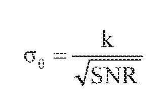
- variable threshold 209 may be viewed as a prediction of the expected worst-case off- boresight error estimate for a point target Measurement noise may be estimated as a variance (i.e., ⁇ 2 ) of the measured boresight angles, referred to as the measurement- variance estimates 217.
- the output of the Markov-chain counter 214 may be a count of the number of times that the the off-boresight error estimates 21 1 exceed the variable threshold 209 within a time window for a predetermined number of samples (i.e., radar returns) processed by the glint detector 212.
- the glint detector 212 may perform an integration or a windowing operation over a predetermined integration or dwell time. In some embodiments, for each sample, the output 213 of the glint detector 212 may indicate when the off- borcsight error estimates 21 1 exceed the variable threshold 209.
- the point-target dcterminator 250 may also include a monopulse variance estimator 216 to generate the measurement- variance estimates 217 from the SNR 205, and a point target classifier 218 to provide the
- the target-state estimator 220 only when the Markov-chain counter 214 indicates that the target 104 is a point target.
- the target 104 may be considered a point target when the output of the Markov-chain counter 214 does not exceed a predetermined number within a time window. Providing the measurement-variance estimates to the target-state estimator 220 allows the target-state estimator 220 to more accurately respond to target power fluctuations that reduce the SNR 105 of the return signals.
- the point target classifier 218 may be configured to refrain from providing the measurement- variance estimates 217 to the target-state estimator 220 when the Markov-chain counter 214 indicates the target 104 is not a point target.
- the target 104 is not considered a point target when the output of the Markov-chain counter 214 exceeds a predetermined number within a time window.
- the target 104 may be considered 'glinty' in which reflections from multiple scatterers (due to target features and shape) of the target 104 have become more significant
- the target-tracking radar 200 may also include a tracking controller 222 to provide tracking control signals 223 to control one or more antennas of the target- tracking radar 200.
- the target-state estimator 220 may calculate target position updates 221 for use by the tracking controller 222 to track the target 104 with the one or more antennas.
- the target-state estimator 220 may also be configured to calculate target velocity and acceleration updates for the tracking controller 222.
- the target-state estimator 220 may be a alman filter, although the scope of the embodiments is not limited in this respect.
- the target-state estimator 220 may be configured use the measurement-variance estimates 217 to calculate the target position updates 221.
- the target-state estimator 220 may be configured to use at least one of filter residuals or a constant value for the measurement noise (e.g., estimated from the measurement- variance estimates 217) to calculate the target position updates 221.
- the measurement- variance estimates 217 may be the estimated boresight angle variance of the target 104 and may be calculated by the following equation:
- the glint detector 212 may compare a total monopulse error (e.g., the off-boresight error estimates 21 1) to a variable threshold (i.e., variable threshold 209) and the glint exceedances are feed a Markov chain up/down counter (e.g., Markov-chain counter 214). This may provide a high probability of detecting when the target's returned energy represents a point target This may be represented by the following equation
- variable threshold 209 which may use a different constant k than the measurement-variance estimates 217 generated by the monopulse variance estimator 216.
- the target-tracking radar 200 may have a sufficiently high bandwidth, however unlike conventional high-bandwidth target-tracking radars, the target-tracking radar 200 may filter-out fluctuations in the off-boresight angles (as described above) for targets where maneuvers are not expected In this way, the target-tracking radar 200 may achieve improved pointing performance, increasing the range at which targets can be engaged.
- the target-tracking radar 200 is illustrated as having several separate functional elements, one or more of the functional elements may be combined and may be implemented by combinations of software-configured elements, such as processing elements including digital signal processors (DSPs), and or other hardware elements.
- processing elements including digital signal processors (DSPs), and or other hardware elements.
- some elements may comprise one or more microprocessors, DSPs, application specific integrated circuits (ASICs), radio- frequency integrated circuits (RFICs) and combinations of various hardware and logic circuitry for performing at least the functions described herein.
- the functional elements of the target-tracking radar 200 may refer to one or more processes operating on one or more processing elements.
- FIG. 3 is a flow chart of a target-tracking procedure in accordance with some embodiments.
- the target-tracking procedure 300 may be performed by a target- tracking radar, such as target-tracking radar 200, although other configurations of target-tracking radars arc also suitable.
- a target- tracking radar such as target-tracking radar 200
- off-borcsight error estimates arc determined based on received radar-return signals.
- an SNR is generated based on the received signals and a measured, estimated or predetermined noise level.
- Operation 306 determines whether a target can be considered a point target based on the SNR and the off-boresight error estimates.
- operation 308 causes operation 310 to be performed.
- operation 308 causes operation 312 to be performed.
- measurement- variance estimates generated from the SNR are provided to a target-state estimator and the target-state estimator may be configured to used measurement-variance estimates to calculate target position updates.
- the target-state estimator may be configured to calculate target position updates without the use of the measurement-variance estimates.
- the target-state estimator may be configured to provide the target position updates to a tracking controller.
- Embodiments may be implemented in one or a combination of hardware, firmware and software. Embodiments may also be implemented as instructions stored on a computer-readable storage device, which may be read and executed by at least one processor to perform the operations described herein.
- a computer- readable storage device may include any non-transitory mechanism for storing information in a form readable by a machine (e.g., a computer).
- a computer-readable storage device may include read-only memory (ROM), random- access memory (RAM), magnetic disk storage media, optical storage media, flash- memory devices, and other storage devices and media.
- die target-tracking radar 200 may include one or more processors and may be configured with instructions stored on a computer-readable storage device.
Landscapes
- Engineering & Computer Science (AREA)
- Radar, Positioning & Navigation (AREA)
- Remote Sensing (AREA)
- Computer Networks & Wireless Communication (AREA)
- Physics & Mathematics (AREA)
- General Physics & Mathematics (AREA)
- Radar Systems Or Details Thereof (AREA)
- Aiming, Guidance, Guns With A Light Source, Armor, Camouflage, And Targets (AREA)
Abstract
Description


Claims
Priority Applications (3)
| Application Number | Priority Date | Filing Date | Title |
|---|---|---|---|
| DE112012001478.2T DE112012001478B4 (en) | 2011-03-30 | 2012-01-30 | Target tracking radar and method for responding to changes in the SNA of the target |
| GB1318161.5A GB2503616B (en) | 2011-03-30 | 2012-01-30 | Target-tracking radar and method for responding to fluctuations in target SNR |
| JP2014502562A JP5770360B2 (en) | 2011-03-30 | 2012-01-30 | Target tracking radar and method responsive to variations in target SNR |
Applications Claiming Priority (2)
| Application Number | Priority Date | Filing Date | Title |
|---|---|---|---|
| US13/075,299 | 2011-03-30 | ||
| US13/075,299 US8803731B2 (en) | 2011-03-30 | 2011-03-30 | Target-tracking radar and method for responding to fluctuations in target SNR |
Publications (1)
| Publication Number | Publication Date |
|---|---|
| WO2012134620A1 true WO2012134620A1 (en) | 2012-10-04 |
Family
ID=46931830
Family Applications (1)
| Application Number | Title | Priority Date | Filing Date |
|---|---|---|---|
| PCT/US2012/023083 Ceased WO2012134620A1 (en) | 2011-03-30 | 2012-01-30 | Target-tracking radar and method for responding to fluctuations in target snr |
Country Status (5)
| Country | Link |
|---|---|
| US (1) | US8803731B2 (en) |
| JP (1) | JP5770360B2 (en) |
| DE (1) | DE112012001478B4 (en) |
| GB (1) | GB2503616B (en) |
| WO (1) | WO2012134620A1 (en) |
Cited By (3)
| Publication number | Priority date | Publication date | Assignee | Title |
|---|---|---|---|---|
| US8803731B2 (en) | 2011-03-30 | 2014-08-12 | Raytheon Company | Target-tracking radar and method for responding to fluctuations in target SNR |
| US8816895B2 (en) | 2011-04-15 | 2014-08-26 | Raytheon Company | Target-tracking radar classifier with glint detection and method for target classification using measured target epsilon and target glint information |
| CN105738891A (en) * | 2014-12-09 | 2016-07-06 | 南京理工大学 | Method for tracking weak maneuvering target angle through airborne digital array radar |
Families Citing this family (10)
| Publication number | Priority date | Publication date | Assignee | Title |
|---|---|---|---|---|
| US20170071512A1 (en) | 2015-09-10 | 2017-03-16 | Dexcom, Inc. | Transcutaneous analyte sensors and monitors, calibration thereof, and associated methods |
| WO2017044654A1 (en) | 2015-09-10 | 2017-03-16 | Dexcom, Inc. | Transcutaneous analyte sensors and monitors, calibration thereof, and associated methods |
| KR101903244B1 (en) * | 2016-11-09 | 2018-10-01 | 국방과학연구소 | Method and apparatus for estimating air combat situation |
| US10495730B1 (en) * | 2017-04-13 | 2019-12-03 | L-3 Communications Corp. | Phase agnostic monopulse tracking |
| CN110515069B (en) * | 2019-08-23 | 2021-08-17 | 中国人民解放军国防科技大学 | An Adaptive Consistency Information Filtering Method for Distributed Target Tracking |
| KR102208175B1 (en) * | 2020-09-02 | 2021-01-27 | 엘아이지넥스원 주식회사 | Adaptive tracking frequency control method of mobile radar |
| KR102705903B1 (en) * | 2022-12-14 | 2024-09-12 | 국방과학연구소 | Method and apparatus for guiding the missile based on deep reinforcement learning, and computer program for the method |
| US20240361445A1 (en) * | 2023-04-26 | 2024-10-31 | Nxp B.V. | Updating radar sensor accuracy measurements for object tracking |
| CN116699550A (en) * | 2023-06-13 | 2023-09-05 | 苏州豪米波技术有限公司 | A Method of Judging Ground Targets Based on Millimeter Wave Radar |
| KR102754925B1 (en) | 2024-06-04 | 2025-01-13 | 국방과학연구소 | Apparatus and method for blanking side lobe |
Citations (7)
| Publication number | Priority date | Publication date | Assignee | Title |
|---|---|---|---|---|
| US5014064A (en) * | 1989-07-10 | 1991-05-07 | Raytheon Company | Monopulse tracking apparatus and method of operating same |
| US5049888A (en) * | 1982-12-30 | 1991-09-17 | Thomson Csf | Method for instantaneous processing of the glint noise and tracking monopulse radar receiver carrying out this method |
| US5960097A (en) * | 1997-01-21 | 1999-09-28 | Raytheon Company | Background adaptive target detection and tracking with multiple observation and processing stages |
| US6229475B1 (en) * | 1987-04-27 | 2001-05-08 | Raytheon Company | Pulse doppler radar system with improved cluster target resolution capability |
| US20030189512A1 (en) * | 2002-04-04 | 2003-10-09 | Hai-Wai Chen | System and method for detecting and estimating the direction of near-stationary targets in monostatic clutter using phase information |
| US20060220951A1 (en) * | 2005-04-04 | 2006-10-05 | Raytheon Company | System and method for coherently combining a plurality of radars |
| US7132977B1 (en) * | 2003-12-22 | 2006-11-07 | Pillai S Unnikrishna | Target identification from a pool of targets using a new adaptive transmitter-receiver design |
Family Cites Families (24)
| Publication number | Priority date | Publication date | Assignee | Title |
|---|---|---|---|---|
| US4533916A (en) * | 1968-08-30 | 1985-08-06 | Hughes Aircraft Company | Monopulsed radar system for tracking ground targets |
| US3935572A (en) * | 1973-11-23 | 1976-01-27 | Hughes Aircraft Company | System for resolving velocity ambiguity in pulse-doppler radar |
| US3952304A (en) * | 1973-11-23 | 1976-04-20 | Hughes Aircraft Company | Tracking system utilizing Kalman filter concepts |
| US4387373A (en) * | 1977-04-21 | 1983-06-07 | Westinghouse Electric Corp. | Synthetic monopulse radar |
| FR2396311A1 (en) * | 1977-06-27 | 1979-01-26 | Thomson Csf | ANGULAR MEASUREMENT NOISE REDUCTION DEVICE IN A RADAR AND RADAR SYSTEM INCLUDING SUCH A DEVICE |
| US5576711A (en) * | 1984-10-17 | 1996-11-19 | Martin Marietta Corporation | Monopulse signal processor and method using same |
| US6930633B1 (en) | 1988-03-22 | 2005-08-16 | Raytheon Company | Adaptive glint reduction method and system |
| JPH03183982A (en) * | 1989-12-14 | 1991-08-09 | Mitsubishi Electric Corp | Method and device for target tracking |
| US5400035A (en) | 1993-12-23 | 1995-03-21 | Hughes Aircraft Company | False track discrimination in the sidelobe region of a monopulse antenna |
| JPH09101363A (en) * | 1995-10-06 | 1997-04-15 | Toshiba Corp | Location radar device |
| US6215115B1 (en) * | 1998-11-12 | 2001-04-10 | Raytheon Company | Accurate target detection system for compensating detector background levels and changes in signal environments |
| JP4258941B2 (en) | 1999-06-03 | 2009-04-30 | 株式会社デンソー | Radar equipment |
| JP3819237B2 (en) * | 2000-12-26 | 2006-09-06 | 三菱電機株式会社 | Tracking device |
| US6710743B2 (en) * | 2001-05-04 | 2004-03-23 | Lockheed Martin Corporation | System and method for central association and tracking in passive coherent location applications |
| US7924218B2 (en) | 2004-09-03 | 2011-04-12 | American Systems Corp. | System for enhanced detection of a target |
| US7236123B2 (en) | 2004-09-03 | 2007-06-26 | American Systems Corporation | System for enhanced detection of a target |
| US7567203B2 (en) * | 2005-04-11 | 2009-07-28 | Raytheon Canada Limited | Classification system for radar and sonar applications |
| US7330149B2 (en) * | 2006-02-09 | 2008-02-12 | The United States Of America As Represented By The Secretary Of The Navy | Method for locating multiple angle sources using a monopulse radar |
| DE102007018190B3 (en) * | 2007-04-18 | 2009-01-22 | Lfk-Lenkflugkörpersysteme Gmbh | Method for ascertaining motion of target object involves utilizing semi-martingale algorithm based on model equations that represented by smooth semi-martingales for estimating motion |
| EP2294444A1 (en) | 2008-05-05 | 2011-03-16 | Raytheon Company | Methods and apparatus for detection/classification of radar targets including birds and other hazards |
| US7667638B1 (en) * | 2009-02-26 | 2010-02-23 | Northrop Grumman Systems Corporation | Detection and resolution of closely spaced targets in a monopulse system |
| JP2010223895A (en) * | 2009-03-25 | 2010-10-07 | Mitsubishi Electric Corp | Radar equipment |
| US8803731B2 (en) | 2011-03-30 | 2014-08-12 | Raytheon Company | Target-tracking radar and method for responding to fluctuations in target SNR |
| US8816895B2 (en) | 2011-04-15 | 2014-08-26 | Raytheon Company | Target-tracking radar classifier with glint detection and method for target classification using measured target epsilon and target glint information |
-
2011
- 2011-03-30 US US13/075,299 patent/US8803731B2/en active Active
-
2012
- 2012-01-30 DE DE112012001478.2T patent/DE112012001478B4/en active Active
- 2012-01-30 WO PCT/US2012/023083 patent/WO2012134620A1/en not_active Ceased
- 2012-01-30 JP JP2014502562A patent/JP5770360B2/en active Active
- 2012-01-30 GB GB1318161.5A patent/GB2503616B/en active Active
Patent Citations (7)
| Publication number | Priority date | Publication date | Assignee | Title |
|---|---|---|---|---|
| US5049888A (en) * | 1982-12-30 | 1991-09-17 | Thomson Csf | Method for instantaneous processing of the glint noise and tracking monopulse radar receiver carrying out this method |
| US6229475B1 (en) * | 1987-04-27 | 2001-05-08 | Raytheon Company | Pulse doppler radar system with improved cluster target resolution capability |
| US5014064A (en) * | 1989-07-10 | 1991-05-07 | Raytheon Company | Monopulse tracking apparatus and method of operating same |
| US5960097A (en) * | 1997-01-21 | 1999-09-28 | Raytheon Company | Background adaptive target detection and tracking with multiple observation and processing stages |
| US20030189512A1 (en) * | 2002-04-04 | 2003-10-09 | Hai-Wai Chen | System and method for detecting and estimating the direction of near-stationary targets in monostatic clutter using phase information |
| US7132977B1 (en) * | 2003-12-22 | 2006-11-07 | Pillai S Unnikrishna | Target identification from a pool of targets using a new adaptive transmitter-receiver design |
| US20060220951A1 (en) * | 2005-04-04 | 2006-10-05 | Raytheon Company | System and method for coherently combining a plurality of radars |
Cited By (3)
| Publication number | Priority date | Publication date | Assignee | Title |
|---|---|---|---|---|
| US8803731B2 (en) | 2011-03-30 | 2014-08-12 | Raytheon Company | Target-tracking radar and method for responding to fluctuations in target SNR |
| US8816895B2 (en) | 2011-04-15 | 2014-08-26 | Raytheon Company | Target-tracking radar classifier with glint detection and method for target classification using measured target epsilon and target glint information |
| CN105738891A (en) * | 2014-12-09 | 2016-07-06 | 南京理工大学 | Method for tracking weak maneuvering target angle through airborne digital array radar |
Also Published As
| Publication number | Publication date |
|---|---|
| US8803731B2 (en) | 2014-08-12 |
| GB201318161D0 (en) | 2013-11-27 |
| US20130328714A1 (en) | 2013-12-12 |
| GB2503616B (en) | 2015-09-23 |
| DE112012001478B4 (en) | 2016-09-15 |
| DE112012001478T5 (en) | 2013-12-24 |
| JP5770360B2 (en) | 2015-08-26 |
| JP2014514550A (en) | 2014-06-19 |
| GB2503616A (en) | 2014-01-01 |
Similar Documents
| Publication | Publication Date | Title |
|---|---|---|
| US8803731B2 (en) | Target-tracking radar and method for responding to fluctuations in target SNR | |
| US8816895B2 (en) | Target-tracking radar classifier with glint detection and method for target classification using measured target epsilon and target glint information | |
| Aprile et al. | Track-before-detect for sea clutter rejection: Tests with real data | |
| US7425916B2 (en) | Airborne distributed pulse doppler radar missile warning system | |
| EP1267444A2 (en) | Adaptive digital sub-array beamforming and deterministic sum and difference beamforming with jamming cancellation and monopulse ratio preservation | |
| EP3588135B1 (en) | Method of determining an alignment error of an antenna and vehicle with an antenna and a detection device | |
| EP2946163A1 (en) | A missile seeker and guidance method | |
| KR101929512B1 (en) | Apparatus for predicting target’s angle of attack using angle information combination technique of millimeter wave air-to-ground radar and method thereof | |
| WO2010039299A1 (en) | Counter target acquisition radar and acoustic adjunct for classification | |
| US8963765B1 (en) | System and method for detecting use of booster rockets by ballistic missiles | |
| EP2788789B1 (en) | Method for determining the impact point of a projectile fired at a target above sea surface, and radar system implementing such method | |
| US20110267218A1 (en) | System and Method for Reduction of Point of Origin Errors | |
| CN104569946B (en) | A kind of electronic fuse antijamming capability quantization signifying method based on coefficient correlation | |
| US4891648A (en) | Aircraft radar arrangement | |
| US11067686B2 (en) | Obstacle position and extent measurement by automotive radar | |
| KR20080054786A (en) | Noise Jamming Signal Detection System and Method Improved by Lobe Eliminator | |
| KR102863163B1 (en) | Systems and methods for multipath beam nulling | |
| JP2016090167A (en) | Impact point observation system | |
| KR102599085B1 (en) | Method and system for determining false alarms by radar clutter signals | |
| KR20250041811A (en) | Target detection direction identification system using doppler information measured in ultra high frequency proximity fuses and optimal warhead detonation time calculation method using it | |
| Geng et al. | The influence of synchronous blinking jamming on monopulse radar seeker angular resolution | |
| Lu et al. | Achieving target identification for the MMW seeker based on scanning matching and beam pointing | |
| Amenabar | Semi-Empirical Approach for Missile Seeker Sizing | |
| Klemm et al. | New results on convoy tracking by airborne radar | |
| Yong et al. | Comparative study of two methods of tracking point selection |
Legal Events
| Date | Code | Title | Description |
|---|---|---|---|
| 121 | Ep: the epo has been informed by wipo that ep was designated in this application |
Ref document number: 12763459 Country of ref document: EP Kind code of ref document: A1 |
|
| ENP | Entry into the national phase |
Ref document number: 2014502562 Country of ref document: JP Kind code of ref document: A |
|
| WWE | Wipo information: entry into national phase |
Ref document number: 112012001478 Country of ref document: DE Ref document number: 1120120014782 Country of ref document: DE |
|
| ENP | Entry into the national phase |
Ref document number: 1318161 Country of ref document: GB Kind code of ref document: A Free format text: PCT FILING DATE = 20120130 |
|
| WWE | Wipo information: entry into national phase |
Ref document number: 1318161.5 Country of ref document: GB |
|
| 122 | Ep: pct application non-entry in european phase |
Ref document number: 12763459 Country of ref document: EP Kind code of ref document: A1 |