WO2012132516A1 - 体組成改善装置 - Google Patents
体組成改善装置 Download PDFInfo
- Publication number
- WO2012132516A1 WO2012132516A1 PCT/JP2012/051395 JP2012051395W WO2012132516A1 WO 2012132516 A1 WO2012132516 A1 WO 2012132516A1 JP 2012051395 W JP2012051395 W JP 2012051395W WO 2012132516 A1 WO2012132516 A1 WO 2012132516A1
- Authority
- WO
- WIPO (PCT)
- Prior art keywords
- body composition
- electrode
- stimulation
- unit
- stimulation current
- Prior art date
- Legal status (The legal status is an assumption and is not a legal conclusion. Google has not performed a legal analysis and makes no representation as to the accuracy of the status listed.)
- Ceased
Links
Images









Classifications
-
- A—HUMAN NECESSITIES
- A61—MEDICAL OR VETERINARY SCIENCE; HYGIENE
- A61N—ELECTROTHERAPY; MAGNETOTHERAPY; RADIATION THERAPY; ULTRASOUND THERAPY
- A61N1/00—Electrotherapy; Circuits therefor
- A61N1/02—Details
- A61N1/04—Electrodes
- A61N1/0404—Electrodes for external use
- A61N1/0472—Structure-related aspects
- A61N1/0484—Garment electrodes worn by the patient
-
- A—HUMAN NECESSITIES
- A61—MEDICAL OR VETERINARY SCIENCE; HYGIENE
- A61B—DIAGNOSIS; SURGERY; IDENTIFICATION
- A61B5/00—Measuring for diagnostic purposes; Identification of persons
- A61B5/05—Detecting, measuring or recording for diagnosis by means of electric currents or magnetic fields; Measuring using microwaves or radio waves
- A61B5/053—Measuring electrical impedance or conductance of a portion of the body
- A61B5/0537—Measuring body composition by impedance, e.g. tissue hydration or fat content
-
- A—HUMAN NECESSITIES
- A61—MEDICAL OR VETERINARY SCIENCE; HYGIENE
- A61N—ELECTROTHERAPY; MAGNETOTHERAPY; RADIATION THERAPY; ULTRASOUND THERAPY
- A61N1/00—Electrotherapy; Circuits therefor
- A61N1/18—Applying electric currents by contact electrodes
- A61N1/32—Applying electric currents by contact electrodes alternating or intermittent currents
- A61N1/321—Electromedical belts
Definitions
- the present invention relates to a body composition improving apparatus for maintaining and improving health.
- An example of a conventional body composition improving apparatus is an electromuscular stimulation belt as disclosed in Japanese Patent Application Laid-Open No. 2010-172562 (Patent Document 1).
- This electric muscle stimulation belt is applied with low-frequency electrical stimulation to the muscles to force the muscles to contract and relax, increasing the amount of muscle activity (energy consumption) and increasing the amount of muscles. It also increases metabolism and changes the body to make it easier to diet.
- the intensity of the low-frequency electrical stimulation is adjusted based on the subjective judgment of the user and may not be an appropriate intensity for improving the body composition.
- the intensity pattern of the low frequency electrical stimulation must be selected in advance in the body composition improving apparatus, and may not be suitable for the body composition of the user. As a result, effective body composition improvement may not be obtained.
- This invention was made in order to improve such a subject, and the body which enables the provision of the optimal low frequency electrical stimulation according to a user's body composition by measuring a user's body composition.
- the object is to provide a composition improving apparatus.
- the body composition improving apparatus comprises a body composition measuring unit for measuring a body composition of a living body, a stimulation current applying unit for applying a stimulation by current to the living body, and a control unit.
- the composition measuring unit includes a body composition measuring electrode that comes into contact with the living body when measuring the body composition of the living body, and the stimulation current applying unit applies the current to the living body when applying stimulation by the current to the living body.
- the control unit determines a condition for applying the stimulation current to be applied to the living body based on the body composition information obtained by the body composition measurement unit using the body composition measurement electrode. Then, a stimulation current according to the application condition is applied to the stimulation current application electrode.
- the body composition improving apparatus further includes a storage unit that records a change with time of the body composition of the living body.
- control unit determines the application condition based on information on a change in body composition over time recorded in the storage unit.
- the body composition improving apparatus further includes a display unit that displays a change with time of the body composition recorded in the storage unit.
- the body composition information is the body fat related amount or the lean body related amount of the living body, and the stimulation current strength, the stimulation time, and the electrode interval are determined as the application conditions.
- the body composition measurement electrode and the stimulation current application electrode are the same biological contact electrode, and the control unit uses the biological contact electrode as the body composition measurement electrode, A switching unit for switching between the case where the contact electrode is used as the stimulation current application electrode is included.
- a body composition improving apparatus that can apply an optimal low-frequency electrical stimulation in accordance with a user's body composition by measuring the body composition of the user.
- the “torso” is a portion excluding the head, neck and limbs of the body, and corresponds to a so-called trunk.
- “Back” means a portion of the torso located on the back side, and corresponds to a portion of the torso excluding the abdominal portion and the chest portion.
- “Back surface” means the entire body surface of the back, and refers to the entire body surface of a portion that is visible when the user is observed from the back side.
- the “body axis” refers to an axis located along the extending direction of the torso, that is, an axis extending in a direction substantially perpendicular to the cross section of the user's torso.
- FIG. 1 is a schematic diagram illustrating an example of a wearing state of the user 1000 of the body composition improving apparatus 1
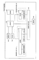
- FIG. 2 is a block diagram of the body composition improving apparatus 1.
- This body composition improving apparatus 1 has a belt member 10 and is used by being mounted on a trunk portion of a user 1000.
- the body composition improving apparatus 1 includes a body composition measuring unit 100 and a stimulation current applying unit 200.
- the body composition measurement unit 100 includes a control unit 110, an abdominal shape measurement unit 120, and a bioimpedance measurement unit 130.
- the stimulation current applying unit 200 includes a control unit 210 and a stimulation waveform generation unit 220.
- the body composition improving apparatus 1 includes a main control unit 300, an electrode switching unit 400, an electrode unit 500, an operation unit 600, a display unit 700, and a storage unit 800.
- the electrode unit 500 is connected to the electrode switching unit 400, and the electrode switching unit 400 is connected to the bioimpedance measurement unit 130 and the stimulation waveform generation unit 220.
- the abdominal shape measurement unit 120 and the bioelectrical impedance measurement unit 130 are connected to the control unit 110 of the body composition measurement unit 100.
- the stimulation waveform generation unit 220 is connected to the control unit 210 of the stimulation current applying unit 200.
- the electrode switching unit 400, the control unit 110 of the body composition measurement unit 100, and the control unit 210 of the stimulation current applying unit 200 are connected to the main control unit 300.
- An operation unit 600, a display unit 700, and a storage unit 800 are also connected to the main control unit 300.
- the main control unit 300 determines conditions for applying the stimulation current to be applied to the user 1000 based on the body composition information obtained by the body composition measuring unit 100 using the electrode unit 500. Thereafter, in the electrode switching unit 400, the connection of the electrode unit 500 is switched from the body composition measurement unit 100 to the stimulation waveform generation unit 220, and a stimulation current corresponding to the application condition is applied from the stimulation waveform generation unit 220 to the electrode unit 500. .
- FIGS. 3 is a front view of the body composition improving apparatus 1
- FIG. 4 is a side view of the body composition improving apparatus 1
- FIG. 5 is a plan view of the body composition improving apparatus 1
- FIG. It is a schematic diagram which shows the arrangement
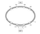
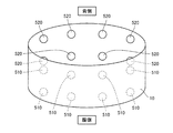
- a plurality of abdominal electrodes 510 and back electrodes 520 are arranged as electrode unit 500 on belt member 10.
- a total of eight abdominal electrodes 510 are arranged in four rows along the periphery of the trunk and two rows along the body axis direction.
- a total of eight back electrodes 520 are arranged on the back side, four rows along the periphery of the trunk and two rows along the body axis direction.
- the abdominal electrode 510 and the back electrode 520 are made of stainless steel having a surface area of about 3 to 80 cm 2, metals usually used as bioelectrodes such as titanium-based metals and whites, and furthermore, an electrolyte is applied to these surfaces. A liquid, gel, or paste applied or pasted is used.
- the arrangement interval (dimension W in FIG. 8) will be described in the setting of stimulation current described later.
- FIG. 7 is a diagram showing a body composition improvement flow of the body composition improving apparatus 1.
- the double frame indicates the operation on the user side
- the single frame indicates the operation on the body composition improving apparatus 1 side.
- the body composition improving apparatus 1 is mounted on the user's torso using the belt member 10.
- the power of the body composition improving apparatus 1 is turned on using a power switch (not shown) provided in the operation unit 600 (step 10, hereinafter referred to as S10).
- initial setting is performed on the body composition improving apparatus 1 side (S20).
- a stimulus menu is selected from the operation unit 600 of the body composition improving apparatus 1 (S30).
- body composition is measured on the body composition improving apparatus 1 side (S40). Specifically, measurement of abdominal shape measurement (S41) and bioimpedance measurement (S42) are performed.
- the stimulation pattern suitable for the user is generated based on the body composition obtained by the measurement of the abdominal shape and the measurement of the bioelectrical impedance (S50).
- the stimulation pattern application condition is based on the information on the temporal change of the body composition recorded in the storage unit 800 that records the temporal change of the body composition of the user 1000. It is determined by the control unit 110 of the composition measuring unit and the control unit 210 of the stimulation current applying unit.
- the electrode is switched from the bioimpedance measurement state to the stimulation current application state (S60). Thereafter, a current having a stimulation waveform is generated and applied to the electrode (S70). The elapse of a predetermined time is measured (S80), and after the elapse of the predetermined time, application of a current having a stimulation waveform to the electrode is terminated (S90).
- the measurement of the abdomen shape includes a method of measuring the trunk circumference (so-called waist length) using a belt, and a method of measuring the width and length of the trunk. These abdominal shape data are sent to the control unit 100.
- FIG. 8 is a schematic diagram showing a bioimpedance measurement example (a dorsal bioimpedance measurement example) during body composition measurement using the body composition improving apparatus.
- the bioimpedance measurement on the dorsal side In the measurement of the bioimpedance at the time of measuring the body composition of the user, in the case of the bioimpedance measurement on the dorsal side, a constant current is applied using the two pairs of back electrodes 520 located on the inside, and the outside 2 is located. A backside voltage measurement is performed using a pair of back electrodes 520. Similarly, the voltage on the ventral side is also measured. Based on the voltage value on the back side and the voltage value on the ventral side thus detected, the bioelectrical impedance of the whole body is calculated.
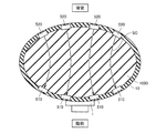
- FIG. 9 is a schematic diagram showing a state at the time of applying a low-frequency stimulation current using the body composition improving apparatus. After the electrode is switched from the bioimpedance measurement state to the stimulation current application state, a current having a stimulation waveform is generated and applied to the back electrode 520 so that the current penetrates the user's abdomen from the back electrode 520. It will flow toward the abdominal electrode 510.
- FIG. 10 is a diagram illustrating specific criteria for determining the body shape of the user
- FIG. 11 is a diagram illustrating an example of setting of the stimulation current
- FIG. 12 is a diagram illustrating setting of the stimulation intensity when corresponding to the obesity state.
- FIG. 13 is a diagram showing an example (basic concept)
- FIG. 13 is a diagram showing an example of a setting of stimulation intensity (a combination of subcutaneous fat-type obesity and visceral fat-type obesity) corresponding to the obesity state.
- the determination of obesity is determined to be obesity when BMI> 25.
- BMI is a numerical value obtained by weight (kg) / (height (m)) 2 .
- visceral fat type obesity is determined as “visceral fat type obesity” when the visceral fat area is 100 cm 2 or more or the V / S ratio is 0.4 or more.
- V is the visceral fat area
- S is the subcutaneous fat area.
- subcutaneous fat type obesity is determined as “subcutaneous fat type obesity” when BMI> 25 and the abdominal circumference is less than a reference value (85 cm for men and 90 cm for women). The above is a body fat related amount, but a method of classifying by a lean body related amount (muscle mass) is also included.
- visceral fat type obesity or “subcutaneous fat type obesity” is roughly classified into “mild”, “medium”, and “severe”, respectively.
- visceral fat obesity if the visceral fat area is less than 100 cm 2 are “mild”, if the visceral fat area of 100 cm 2 ⁇ 150 cm 2 is "moderate”, visceral fat area is 150 cm 2 or more In this case, the judgment is “severe”.
- subcutaneous fat type obesity when the subcutaneous fat area is less than 180 cm 2 and the bioimpedance from the abdominal body surface is less than 10 ⁇ , it is “mild”, and the subcutaneous fat area is 180 cm 2 to 250 cm 2 “Medium” when the bioimpedance from the abdominal body surface is 10 ⁇ to 15 ⁇ , and “Severe” when the subcutaneous fat area is 250 cm 2 or more and the bioimpedance from the abdominal body surface is 15 ⁇ or more. Judgment is made.
- the whole body bioimpedance (mainly reflecting muscle mass) is “less” if it is 10 ⁇ or more, the whole body bioimpedance (mainly reflecting muscle mass) ) Is 5 ⁇ to 10 ⁇ , “normal” is determined, and when the whole body bioimpedance (mainly reflecting muscle mass) is less than 5 ⁇ , “high” is determined.
- stimulation current setting Next, the setting of the stimulation current will be described with reference to FIG.
- “stimulation current strength” is 20 mA
- “stimulation time” is 10 minutes
- “stimulation electrode interval” is 5 cm.
- the “stimulation current strength” is 40 mA (slightly stronger)
- the “stimulation time” is 15 minutes (slightly longer)
- “stimulation electrode interval” is “Is 10 cm (slightly wider).
- the “stimulation current strength” is 60 mA (strong), the “stimulation time” is 20 minutes (long), and the “stimulation electrode interval” is 15 cm (wide).
- “stimulation current strength” is 80 mA (strongest), “stimulation time” is 30 minutes (longest), and “stimulation electrode interval” is 20 cm (widest).
- stimulation current there are individual differences in the way the user feels the stimulation. Therefore, for users who are not good at strong stimulation current, the value of “stimulation current” is weaker than the setting. However, it is possible to set the “stimulation time” longer than the setting.
- the average rate of change from before weight loss is shown.
- the graph shown in FIG. 14 is a change over time of the body composition recorded in the storage unit 800, and is continuously displayed for each measurement date on the display unit 700 (see FIG. 2) of the body composition improving apparatus 1.
- the body composition improving apparatus 1 when the user has improved the body composition, after the body composition of the user is measured in advance, the body composition of the user is maintained while the body composition improving apparatus 1 is worn.
- the appropriate “stimulation current”, “stimulation time” and “electrode spacing” are set.
- the visceral fat area (BIA method) As shown in FIG. 14, the visceral fat area (BIA method), “weight”, “waist circumference”, and Each parameter of “body composition” can be effectively reduced.
- the user can confirm the decrease in each of the above parameters by the display unit 700, the user can maintain motivation to continuously improve the body composition.
- the body composition improving apparatus 1 by knowing the user's body composition by measuring the user's bioimpedance, based on the bioimpedance value and the body composition data obtained from them, It becomes possible to improve the body composition according to the user's physical condition and purpose.
- the electrode for applying the stimulation current can be used as the electrode for body composition measurement, an increase in the size of the apparatus can be suppressed.
- changes over time in the body composition improving effect are displayed.
- body composition measurement and body composition improvement can be performed with a single device, body composition can be improved at an optimal setting value, and the effect of body composition improvement can be maximized.
- the effect of improving the body composition is easily understood by the user, and the motivation for improving the body composition is improved, and the success rate of improving the body composition is increased.
- the arrangement of the abdominal electrode 510 and the back electrode 520 on the belt member 10 is not limited to the arrangement pattern shown in FIG. 6, and as shown in FIG. It is also possible to arrange a total of four abdominal electrodes 510 in four rows and one row around the abdomen. In addition, as shown in FIG. 16, the abdominal electrode 510 may be arranged at a total of five positions including a position corresponding to four corners of a quadrangle and a position where diagonal lines intersect. .
- electrode part 500 is arrange
- stimulation electrodes 530 and 540 are provided on the leg, arm, or back. It is also possible to adopt a configuration in which
- the body composition measurement electrode and the stimulation current application electrode use the same biological contact electrode by providing the electrode switching unit 400 , but without providing the electrode switching unit 400, the body It is also possible to employ a configuration in which a composition measurement electrode and a stimulation current application electrode are provided.
- the belt member 10 is attached to the abdomen and the improvement of the body composition in the abdomen is described, it is not limited to the abdomen.
- 1 body composition improving device 10 belt member, 100 body composition measuring unit, 110, 210 control unit, 120 abdominal shape measuring unit, 130 bioimpedance measuring unit, 200 stimulation current applying unit, 220 stimulation waveform generating unit, 300 main control unit , 400 electrode switching unit, 500 electrode unit, 510 abdominal electrode, 520 back electrode, 530, 540 stimulation electrode, 600 operation unit, 700 display unit, 800 storage unit, 1000 user.
Landscapes
- Health & Medical Sciences (AREA)
- Life Sciences & Earth Sciences (AREA)
- Public Health (AREA)
- Nuclear Medicine, Radiotherapy & Molecular Imaging (AREA)
- Radiology & Medical Imaging (AREA)
- Biomedical Technology (AREA)
- Animal Behavior & Ethology (AREA)
- General Health & Medical Sciences (AREA)
- Engineering & Computer Science (AREA)
- Veterinary Medicine (AREA)
- Biophysics (AREA)
- Physics & Mathematics (AREA)
- Pathology (AREA)
- Heart & Thoracic Surgery (AREA)
- Medical Informatics (AREA)
- Molecular Biology (AREA)
- Surgery (AREA)
- Electrotherapy Devices (AREA)
- Measurement And Recording Of Electrical Phenomena And Electrical Characteristics Of The Living Body (AREA)
Abstract
この体組成改善装置は、体組成測定部(100)と刺激電流付与部(200)と主制御部(300)とを備え、体組成測定部(100)は、使用者に接触する体組成測定電極(500)を含み、刺激電流付与部(200)は、使用者に接触する刺激電流付与電極(500)を含み、主制御部(300)は、体組成測定電極(500)を用いて体組成測定部(100)によって得られた体組成情報に基づき、使用者に付与する刺激電流の付与条件を決定して、この付与条件に応じた刺激電流を刺激電流与電極(500)に与える。
Description
本発明は、健康の維持および増進のための体組成改善装置に関する。
従来の体組成改善装置の一例としては、特開2010-172562号公報(特許文献1)に開示されるような、電気筋肉刺激ベルトが挙げられる。この電気筋肉刺激ベルトは、低周波電気刺激を筋肉に与えることによって、筋肉を強制的に収縮・弛緩運動させて、筋肉の活動量(エネルギー消費)を増加させるとともに、筋肉量を増やすことによって基礎代謝も増加させて、ダイエットしやすい体に変化させるというものである。
しかしながら、このような体組成改善装置にあっては、低周波電気刺激の強度は使用者の主観的な判断で調節され、体組成の改善のための適切な強度になっていない場合がある。また、低周波電気刺激の強度パターンは、あらかじめ体組成改善装置に内蔵されたものを選択するしかなく、使用者の体組成に適合していない場合がある。その結果、効果的な体組成の改善が得られない場合がある。
この発明は、このような課題を改善するためになされたもので、使用者の体組成を測定することで、使用者の体組成にあわせた最適な低周波電気刺激の付与を可能とする体組成改善装置を提供することにある。
この発明に基づいた体組成改善装置においては、生体の体組成を測定する体組成測定部と、上記生体に対して電流による刺激を付与する刺激電流付与部と、制御部とを備え、上記体組成測定部は、上記生体の体組成を測定する際に上記生体に接触する体組成測定電極を含み、上記刺激電流付与部は、上記生体に対して電流による刺激を付与する際に上記生体に接触する刺激電流付与電極を含み、上記制御部は、上記体組成測定電極を用いて上記体組成測定部によって得られた体組成情報に基づき、上記生体に付与する刺激電流の付与条件を決定して、上記付与条件に応じた刺激電流を上記刺激電流付与電極に与える。
他の形態においては、当該体組成改善装置は、上記生体の体組成の経時的変化を記録する記憶部をさらに含む。
他の形態においては、上記制御部は、上記記憶部に記録された体組成の経時的変化の情報に基づき上記付与条件を決定する。
他の形態においては、当該体組成改善装置は、上記記憶部に記録された上記体組成の経時的変化を表示する表示部をさらに含む。
他の形態においては、上記体組成情報は、上記生体の体脂肪関連量または除脂肪関連量であり、上記付与条件として、上記刺激電流の強さ、刺激時間、および電極間隔が決定される。
他の形態においては、上記体組成測定電極と上記刺激電流付与電極とは同一の生体接触電極が用いられ、上記制御部は、上記生体接触電極を上記体組成測定電極として用いる場合と、上記生体接触電極を上記刺激電流付与電極として用いる場合とを切り換える切り換え部を含む。
本発明によれば、使用者の体組成を測定することで、使用者の体組成にあわせた最適な低周波電気刺激の付与を可能とする体組成改善装置を提供することを可能とする。
以下、この発明に基づいた実施の形態における体組成改善装置について図面を参照して詳細に説明する。なお、以下に説明する実施の形態において、個数、量などに言及する場合、特に記載がある場合を除き、本発明の範囲は必ずしもその個数、量などに限定されない。また、各図中、同一符号は同一または相当部分を指し、重複する説明は繰返さない場合がある。
まず、本発明の各実施の形態について説明するに先立ち、身体の部位を表わす用語の定義を行なう。「胴部」は、身体の頭部、頸部、および四肢を除く部位であり、いわゆる体幹に相当する。「背部」は、上記胴部のうちの背中側に位置する部分を意味し、上記胴部のうちの腹部側の部分および胸部側の部分を除く部分に相当する。「背部表面」は、上記背部の体表面全体を意味しており、使用者を背中側から観察した場合に視認可能な部分の胴部表面の全体を言う。また、「体軸」は、胴部の延在方向に沿って位置する軸、すなわち使用者の胴部の横断面に対して略垂直な方向に延びる軸を言う。
(体組成改善装置1)
図1および図2を参照して、本実施の形態における体組成改善装置1について説明する。なお、図1は、体組成改善装置1の使用者1000の装着状態の一例を示す模式図であり、図2は、体組成改善装置1のブロック図である。
図1および図2を参照して、本実施の形態における体組成改善装置1について説明する。なお、図1は、体組成改善装置1の使用者1000の装着状態の一例を示す模式図であり、図2は、体組成改善装置1のブロック図である。
この体組成改善装置1は、ベルト部材10を有し、使用者1000の胴部に装着して使用する。体組成改善装置1は、体組成測定部100と刺激電流付与部200とを含む。体組成測定部100は、制御部110、腹部形状測定部120および生体インピーダンス測定部130を有する。刺激電流付与部200は、制御部210および刺激波形発生部220を有する。
また、体組成改善装置1は、主制御部300、電極切り換え部400、電極部500、操作部600、表示部700、および、記憶部800を含む。
電極部500は、電極切り換え部400に接続され、電極切り換え部400は、生体インピーダンス測定部130および刺激波形発生部220に接続されている。腹部形状測定部120および生体インピーダンス測定部130は、体組成測定部100の制御部110に接続されている。刺激波形発生部220は、刺激電流付与部200の制御部210に接続されている。
また、電極切り換え部400、体組成測定部100の制御部110、および刺激電流付与部200の制御部210は、主制御部300に接続されている。操作部600、表示部700、および、記憶部800も、主制御部300に接続されている。
主制御部300は、電極部500を用いて体組成測定部100によって得られた体組成情報に基づき、使用者1000に付与する刺激電流の付与条件を決定する。その後、電極切り換え部400において、電極部500は体組成測定部100から刺激波形発生部220へ接続が切り換えられて、付与条件に応じた刺激電流が刺激波形発生部220から電極部500に与えられる。
(電極の配置)
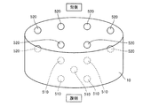
次に、図3から図6を参照して、ベルト部材10を用いた体組成改善装置1の具体的な電極配置について説明する。なお、図3は、体組成改善装置1の正面図、図4は、体組成改善装置1の側面図、図5は、体組成改善装置1の平面図、図6は、体組成改善装置1の腹部電極および背部電極の配置状態を示す模式図である。
次に、図3から図6を参照して、ベルト部材10を用いた体組成改善装置1の具体的な電極配置について説明する。なお、図3は、体組成改善装置1の正面図、図4は、体組成改善装置1の側面図、図5は、体組成改善装置1の平面図、図6は、体組成改善装置1の腹部電極および背部電極の配置状態を示す模式図である。
図5および図6を参照して、ベルト部材10には、電極部500として、複数の腹部電極510および背部電極520が配置されている。腹部側には、胴部周りに沿って4列、体軸方向に沿って2列、合計8個の腹部電極510が配置されている。同様に、背部側にも、胴部周りに沿って4列、体軸方向に沿って2列、合計8個の背部電極520が配置されている。
腹部電極510および背部電極520には、表面積が3~80cm2程度のステンレス材やチタン系金属や洋白などのような生体電極として通常に使用される金属や、さらにはこれらの表面に電解質を含む液体、ゲル、ペーストを塗布または貼り付けしたものが用いられる。配置間隔(図8中の寸法W)については、後述の刺激電流の設定において説明する。
(体組成改善フロー)
次に、図7を参照して、上記体組成改善装置1を用いた体組成改善フローについて説明する。なお、図7は、体組成改善装置1の体組成改善フローを示す図である。なお、図7中の各ブロックにおいて、二重枠は使用者側の操作を示し、一重枠は体組成改善装置1側の動作を示す。
次に、図7を参照して、上記体組成改善装置1を用いた体組成改善フローについて説明する。なお、図7は、体組成改善装置1の体組成改善フローを示す図である。なお、図7中の各ブロックにおいて、二重枠は使用者側の操作を示し、一重枠は体組成改善装置1側の動作を示す。
まず、体組成改善装置1を使用者の胴部にベルト部材10を用いて装着する。次に、操作部600に設けられた、電源スイッチ(図示省略)を用いて体組成改善装置1の電源をON状態にする(ステップ10、以下S10と示す)。次に、体組成改善装置1側において初期設定が行なわれる(S20)。
次に、体組成改善装置1の操作部600から、刺激メニューの選択を行なう(S30)。次に、体組成改善装置1側において、体組成の測定が行なわれる(S40)。具体的には、腹部形状の測定(S41)と生体インピーダンスの測定(S42)との測定が行なわれる。
次に、腹部形状の測定および生体インピーダンスの測定によって得られた体組成に基づき、使用者に適した刺激パターンの生成を行なう(S50)。刺激パターンの生成においては、使用者1000の体組成の経時的変化を記録する記憶部800に記録された体組成の経時的変化の情報に基づき刺激パターンの付与条件が、主制御部300、体組成測定部の制御部110、および刺激電流付与部の制御部210において決定される。
次に、電極を生体インピーダンス測定状態から刺激電流付与状態に切り換える(S60)。その後、刺激波形を有する電流を発生させて、電極に印加する(S70)。所定時間の経過を計測し(S80)、所定時間の経過後、刺激波形を有する電流の電極への印加を終了する(S90)。
(腹部形状の測定および生体インピーダンスの測定)
次に、腹部形状の測定および生体インピーダンスの測定について説明する。まず、腹部形状の測定は、ベルトを用いて胴部周囲長(いわゆるウエスト長)を測定する方法や、胴部の横幅および縦幅を測定する方法がある。これらの腹部形状のデータが、制御部100に送られる。
次に、腹部形状の測定および生体インピーダンスの測定について説明する。まず、腹部形状の測定は、ベルトを用いて胴部周囲長(いわゆるウエスト長)を測定する方法や、胴部の横幅および縦幅を測定する方法がある。これらの腹部形状のデータが、制御部100に送られる。
次に、図8を参照して、生体インピーダンスの測定について説明する。なお、図8は、体組成改善装置を用いた体組成測定時の生体インピーダンス測定例(背側生体インピーダンス測定例)を示す模式図である。
使用者の体組成測定時の生体インピーダンスの測定においては、背側の生体インピーダンス測定の場合、内側に位置する2組1対の背部電極520を用いて定電流印加を行ない、外側に位置する2組1対の背部電極520を用いて背側の電圧測定を行なう。同様にして、腹側の電圧測定も行なう。このようにして検出された背側の電圧値および腹側の電圧値に基づき、全身の生体インピーダンスが算出される。
(刺激波形を有する電流の印加)
次に、図9を参照して、刺激波形を有する電流の印加について説明する。なお、図9は、体組成改善装置を用いた低周波刺激電流の印加時の状態を示す模式図である。電極を生体インピーダンス測定状態から刺激電流付与状態に切り換えた後、刺激波形を有する電流を発生させて、背部電極520に印加することで電流は使用者の腹部を貫通するように、背部電極520から腹部電極510に向かって流れることになる。
次に、図9を参照して、刺激波形を有する電流の印加について説明する。なお、図9は、体組成改善装置を用いた低周波刺激電流の印加時の状態を示す模式図である。電極を生体インピーダンス測定状態から刺激電流付与状態に切り換えた後、刺激波形を有する電流を発生させて、背部電極520に印加することで電流は使用者の腹部を貫通するように、背部電極520から腹部電極510に向かって流れることになる。
(刺激パターンの生成)
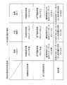
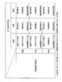
次に、図10から図13を参照して、主制御部300(図2参照)における刺激パターンの生成について説明する。なお、図10は、使用者の体型の具体的判断基準を示す図、図11は、刺激電流の設定の一例を示す図、図12は、肥満の状態に対応した場合の刺激強度の設定の一例(基本的な考え方)を示す図、図13は、肥満の状態に対応した場合の刺激強度の設定の一例(皮下脂肪型肥満と内臓脂肪型肥満との組合)を示す図である。
次に、図10から図13を参照して、主制御部300(図2参照)における刺激パターンの生成について説明する。なお、図10は、使用者の体型の具体的判断基準を示す図、図11は、刺激電流の設定の一例を示す図、図12は、肥満の状態に対応した場合の刺激強度の設定の一例(基本的な考え方)を示す図、図13は、肥満の状態に対応した場合の刺激強度の設定の一例(皮下脂肪型肥満と内臓脂肪型肥満との組合)を示す図である。
(体型の具体的判断基準)
使用者の体型の具体的判断基準について説明する。肥満の判定は、BMI>25の場合に肥満であると判断する。ここで、BMIは、体重(kg)/(身長(m))2で求まる数値である。
使用者の体型の具体的判断基準について説明する。肥満の判定は、BMI>25の場合に肥満であると判断する。ここで、BMIは、体重(kg)/(身長(m))2で求まる数値である。
「内臓脂肪型肥満」の判定は、内臓脂肪面積が100cm2以上、またはV/S比が0.4以上の場合には、「内臓脂肪型肥満」と判定する。ここで、Vは、内臓脂肪面積、Sは皮下脂肪面積である。「皮下脂肪型肥満」の判定は、BMI>25、かつ、腹囲長が基準値(男性で85cm、女性で90cm)未満の場合には、「皮下脂肪型肥満」と判定する。上記は、体脂肪関連量であるが、除脂肪関連量(筋肉量)で分類する方法も挙げられる。
図10を参照して、「内臓脂肪型肥満」または「皮下脂肪型肥満」に大別し、それぞれ、「軽度」、「中度」、「重度」に場合分けを行なう。「内臓脂肪型肥満」の場合、内臓脂肪面積が100cm2未満の場合には「軽度」、内臓脂肪面積が100cm2~150cm2の場合には「中度」、内臓脂肪面積が150cm2以上の場合には「重度」との判定を行なう。
「皮下脂肪型肥満」の場合、皮下脂肪面積が180cm2未満であって、腹部体表からの生体インピーダンスが10Ω未満の場合には「軽度」、皮下脂肪面積が180cm2~250cm2であって、腹部体表からの生体インピーダンスが10Ω~15Ωの場合には「中度」、皮下脂肪面積が250cm2以上であって、腹部体表からの生体インピーダンスが15Ω以上の場合には「重度」との判定を行なう。
なお、除脂肪関連量として筋肉量で分類する場合には、全身の生体インピーダンス(主に筋肉量を反映)が10Ω以上の場合には「少ない」、全身の生体インピーダンス(主に筋肉量を反映)が5Ω~10Ωの場合には「標準」、全身の生体インピーダンス(主に筋肉量を反映)が5Ω未満の場合には「多い」との判定を行なう。
(刺激電流の設定)
次に、図11を参照して、刺激電流の設定について説明する。標準体型の場合「刺激電流の強さ」は20mA、「刺激時間」は10分、「刺激電極間隔」は5cmである。一方、肥満体型の場合には、「軽度」の肥満体型の場合には、「刺激電流の強さ」は40mA(やや強め)、「刺激時間」は15分(やや長め)、「刺激電極間隔」は10cm(やや広く)である。「中度」の肥満体型の場合には、「刺激電流の強さ」は60mA(強め)、「刺激時間」は20分(長め)、「刺激電極間隔」は15cm(広く)である。「重度」の肥満体型の場合には、「刺激電流の強さ」は80mA(最強)、「刺激時間」は30分(最長)、「刺激電極間隔」は20cm(最も広く)である。
次に、図11を参照して、刺激電流の設定について説明する。標準体型の場合「刺激電流の強さ」は20mA、「刺激時間」は10分、「刺激電極間隔」は5cmである。一方、肥満体型の場合には、「軽度」の肥満体型の場合には、「刺激電流の強さ」は40mA(やや強め)、「刺激時間」は15分(やや長め)、「刺激電極間隔」は10cm(やや広く)である。「中度」の肥満体型の場合には、「刺激電流の強さ」は60mA(強め)、「刺激時間」は20分(長め)、「刺激電極間隔」は15cm(広く)である。「重度」の肥満体型の場合には、「刺激電流の強さ」は80mA(最強)、「刺激時間」は30分(最長)、「刺激電極間隔」は20cm(最も広く)である。
刺激電極間隔の調整は、本実施の形態においては、たとえば5cm間隔(図8中のW=5cm)に格子状に配置された複数の電極510,520から、対となる電極の間隔が、5cm、10cm、15cmとなるように選択を行なう。なお、「刺激電流」に関しては、刺激の感じ方に使用者の個人差が生じることから、刺激電流が強いのが苦手な使用者の場合には、「刺激電流」の値を設定よりも弱くし、「刺激時間」を設定よりも長くするような設定方法も可能である。
次に、図12を参照して、肥満の状態に対応した場合の刺激強度の設定の一例(基本的な考え方)について説明する。「内臓脂肪型肥満」の場合、「軽度」であれば、「刺激電流の強さ」は「標準」、「刺激時間」は「やや長め」、「電極間隔」は「標準(5cm)」となり、「中度」であれば、「刺激電流の強さ」は「標準」、「刺激時間」は「長め」、「電極間隔」は「標準(5cm)」となり、「重度」であれば、「刺激電流」は「標準」、「刺激時間」は「最長」、「電極間隔」は「標準(5cm)」となる。
また、「皮下脂肪型肥満」の場合、「軽度」であれば、「刺激電流」は「やや強め」、「刺激時間」は「やや長め」、「電極間隔」は「やや広く」となり、「中度」であれば、「刺激電流」は「強め」、「刺激時間」は「長め」、「電極間隔」は「広く」となり、「重度」であれば、「刺激電流」は「最強」、「刺激時間」は「最長」、「電極間隔」は「最も広く」となる。
次に、図13を参照して、肥満の状態に対応した場合の刺激強度の設定の一例(皮下脂肪型肥満と内臓脂肪型肥満との組合せ)について説明する。「内臓脂肪型肥満」が「軽度」の場合において、「皮下脂肪型肥満」が「軽度」であれば、「刺激電流」は「やや強め」、「刺激時間」は「やや長め」、「電極間隔」は「やや広く」となり、「中度」であれば、「刺激電流」は「強め」、「刺激時間」は「長め」、「電極間隔」は「広く」となり、「重度」であれば、「刺激電流」は「最強」、「刺激時間」は「最長」、「電極間隔」は「最も広く」となる。
また、「内臓脂肪型肥満」が「中度」の場合において、「皮下脂肪型肥満」が「軽度」であれば、「刺激電流」は「やや強め」、「刺激時間」は「やや長め」、「電極間隔」は「やや広く」となり、「中度」であれば、「刺激電流」は「強め」、「刺激時間」は「最長」、「電極間隔」は「広く」となり、「重度」であれば、「刺激電流」は「最強」、「刺激時間」は「最長」、「電極間隔」は「最も広く」となる。
また、「内臓脂肪型肥満」が「重度」の場合において、「皮下脂肪型肥満」が「軽度」であれば、「刺激電流」は「やや強め」、「刺激時間」は「最長」、「電極間隔」は「やや広く」となり、「中度」であれば、「刺激電流」は「強め」、「刺激時間」は「最長」、「電極間隔」は「広く」となり、「重度」であれば、「刺激電流」は「最強」、「刺激時間」は「最長」、「電極間隔」は「最も広く」となる。
次に、図14を参照して、本実施の形態おける体組成改善装置1を用いた使用者の「内臓脂肪面積(BIA法)」、「体重」、「ウエスト周囲長」、および「体組成」の減量前からの平均変化率を示す。図14に示すグラフは、記憶部800に記録された体組成の経時的変化であり、体組成改善装置1の表示部700(図2参照)に測定日ごとに連続して表示される。
体組成改善装置1において、使用者が体組成改善を行なった場合には、予め使用者の体組成が測定された後に、体組成改善装置1を装着した状態のまま、使用者の体組成に適合した、「刺激電流」、「刺激時間」および「電極間隔」が設定される。その結果、使用者の体組成にあわせた最適な低周波電気刺激の付与が可能となり、図14に示すように、内臓脂肪面積(BIA法)」、「体重」、「ウエスト周囲長」、および「体組成」の各パラメータを効果的に減少させることを可能としている。
また、使用者は、上記各パラメータの減少を表示部700により確認することができるため、継続して体組成改善を行なうモチベーションを維持することができる。
このように、本発明に基づいた体組成改善装置1によれば、使用者の生体インピーダンスを測定することにより使用者の体組成を知り、生体インピーダンス値やそれらから得られる体組成データに基づき、使用者の身体状況や目的に合せた体組成の改善を行なうことが可能となる。また、刺激電流を付与する電極と体組成測定用の電極を兼用することができるため、装置の大型化を抑制することができる。また、体組成改善効果の経時的変化を表示している。
その結果、体組成測定と体組成改善とを一つの装置で行なえ、最適な設定値での体組成改善ができ、体組成改善の効果を最大化することができる。また、体組成改善の効果が使用者に理解しやすくなり、体組成改善のモチベーションとなり、体組成改善の成功率が上がる。
なお、ベルト部材10への腹部電極510および背部電極520の配置については、図6に示す配置パターンに限定されるものではなく、図15に示すように、腹部側には、胴部周りに沿って4列、腹部周りに沿って1列、合計4個の腹部電極510を配置することも可能である。また、図16に示すように、腹部電極510の配置として、四角形の4つの角に相当する位置と、対角線が交わる位置との合計5箇所に、腹部電極510を配置するようにしてもかまわない。
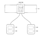
また、ベルト部材を用いて腹部周りに電極部500を配置する場合について説明しているが、図17に示すように、刺激用電極として、脚部、腕部、または背中に刺激電極530,540を設ける構成を採用することも可能である。
なお、上記実施形態では、電極切り換え部400を設けることで、体組成測定電極と刺激電流付与電極とは同一の生体接触電極を用いる場合を説明したが、電極切り換え部400を設けることなく、体組成測定電極と刺激電流付与電極とをそれぞれ設ける構成を採用することも可能である。
また、ベルト部材10を腹部に装着して、腹部における体組成の改善について説明したが腹部に限定されるものではない。たとえば、二の腕、太股等の身体の部位毎にベルト部材10を巻きつけて、部位毎に体組成の改善を行なうことも可能である。
このように、本発明の実施の形態について説明したが、今回開示された実施の形態は全ての点で例示であって制限的なものではないと考えられるべきである。本発明の範囲は請求の範囲によって示され、請求の範囲と均等の意味および範囲内での全ての変更が含まれることが意図される。
1 体組成改善装置、10 ベルト部材、100 体組成測定部、110,210 制御部、120 腹部形状測定部、130 生体インピーダンス測定部、200 刺激電流付与部、220 刺激波形発生部、300 主制御部、400 電極切り換え部、500 電極部、510 腹部電極、520 背部電極、530,540 刺激電極、600 操作部、700 表示部、800 記憶部、1000 使用者。
Claims (6)
- 生体(1000)の体組成を測定する体組成測定部(100)と、
前記生体(1000)に対して電流による刺激を付与する刺激電流付与部(200)と、
主制御部(300)と、を備え、
前記体組成測定部(100)は、前記生体(1000)の体組成を測定する際に前記生体(1000)に接触する体組成測定電極(500)を含み、
前記刺激電流付与部(200)は、前記生体(1000)に対して電流による刺激を付与する際に前記生体(1000)に接触する刺激電流付与電極(500)を含み、
前記主制御部(300)は、前記体組成測定電極(500)を用いて前記体組成測定部(100)によって得られた体組成情報に基づき、前記生体(1000)に付与する刺激電流の付与条件を決定して、前記付与条件に応じた刺激電流を前記刺激電流付与電極(500)に与える、体組成改善装置。 - 当該体組成改善装置は、前記生体(1000)の体組成の経時的変化を記録する記憶部(800)をさらに含む、請求項1に記載の体組成改善装置。
- 前記主制御部(300)は、前記記憶部(800)に記録された体組成の経時的変化の情報に基づき前記付与条件を決定する、請求項2に記載の体組成改善装置。
- 当該体組成改善装置は、前記記憶部(800)に記録された前記体組成の経時的変化を表示する表示部(700)をさらに含む、請求項2に記載の体組成改善装置。
- 前記体組成情報は、前記生体の体脂肪関連量または除脂肪関連量であり、
前記付与条件として、前記刺激電流の強さ、刺激時間、および電極間隔が決定される、請求項1に記載の体組成改善装置。 - 前記体組成測定電極と前記刺激電流付与電極とは同一の生体接触電極(500)が用いられ、
前記主制御部(300)は、前記生体接触電極(500)を前記体組成測定電極として用いる場合と、前記生体接触電極(500)を前記刺激電流付与電極として用いる場合とを切り換える切り換え部(400)を有する、請求項1に記載の体組成改善装置。
Applications Claiming Priority (2)
| Application Number | Priority Date | Filing Date | Title |
|---|---|---|---|
| JP2011078287A JP2012210375A (ja) | 2011-03-31 | 2011-03-31 | 体組成改善装置 |
| JP2011-078287 | 2011-03-31 |
Publications (1)
| Publication Number | Publication Date |
|---|---|
| WO2012132516A1 true WO2012132516A1 (ja) | 2012-10-04 |
Family
ID=46930284
Family Applications (1)
| Application Number | Title | Priority Date | Filing Date |
|---|---|---|---|
| PCT/JP2012/051395 Ceased WO2012132516A1 (ja) | 2011-03-31 | 2012-01-24 | 体組成改善装置 |
Country Status (2)
| Country | Link |
|---|---|
| JP (1) | JP2012210375A (ja) |
| WO (1) | WO2012132516A1 (ja) |
Cited By (3)
| Publication number | Priority date | Publication date | Assignee | Title |
|---|---|---|---|---|
| US11116658B2 (en) | 2015-06-28 | 2021-09-14 | Oberon Sciences Ilan Ltd. | Devices for gastrointestinal stimulation and uses thereof |
| CN114206210A (zh) * | 2019-08-02 | 2022-03-18 | 株式会社百利达 | 生物测量系统、生物测量程序以及计算机可读非暂时性存储介质 |
| US20240115871A1 (en) * | 2022-10-06 | 2024-04-11 | Maria Del Pilar SANCHEZ JAIME | Machine and method for treating visceral fat |
Families Citing this family (3)
| Publication number | Priority date | Publication date | Assignee | Title |
|---|---|---|---|---|
| US10525264B2 (en) | 2016-11-16 | 2020-01-07 | Samsung Electronics Co., Ltd. | Stimulator and method of controlling stimulator |
| US11571136B2 (en) * | 2019-07-01 | 2023-02-07 | Baxter International Inc. | Device and method for sensing signals from a body |
| KR102404945B1 (ko) * | 2019-12-30 | 2022-06-07 | 주식회사 셀로긴 | 스마트 의류를 이용한 다이어트 및 건강 관리 장치 |
Citations (1)
| Publication number | Priority date | Publication date | Assignee | Title |
|---|---|---|---|---|
| WO2003105688A1 (ja) * | 2002-06-01 | 2003-12-24 | ヤーマン株式会社 | 身体の骨量、水分量及び/又は筋肉量を表示する装置 |
-
2011
- 2011-03-31 JP JP2011078287A patent/JP2012210375A/ja not_active Withdrawn
-
2012
- 2012-01-24 WO PCT/JP2012/051395 patent/WO2012132516A1/ja not_active Ceased
Patent Citations (1)
| Publication number | Priority date | Publication date | Assignee | Title |
|---|---|---|---|---|
| WO2003105688A1 (ja) * | 2002-06-01 | 2003-12-24 | ヤーマン株式会社 | 身体の骨量、水分量及び/又は筋肉量を表示する装置 |
Cited By (4)
| Publication number | Priority date | Publication date | Assignee | Title |
|---|---|---|---|---|
| US11116658B2 (en) | 2015-06-28 | 2021-09-14 | Oberon Sciences Ilan Ltd. | Devices for gastrointestinal stimulation and uses thereof |
| CN114206210A (zh) * | 2019-08-02 | 2022-03-18 | 株式会社百利达 | 生物测量系统、生物测量程序以及计算机可读非暂时性存储介质 |
| EP4008395A4 (en) * | 2019-08-02 | 2023-07-19 | Tanita Corporation | BIOLOGICAL MEASUREMENT SYSTEM, BIOLOGICAL MEASUREMENT PROGRAM AND COMPUTER-READABLE NON-TRANSITORY STORAGE MEDIUM |
| US20240115871A1 (en) * | 2022-10-06 | 2024-04-11 | Maria Del Pilar SANCHEZ JAIME | Machine and method for treating visceral fat |
Also Published As
| Publication number | Publication date |
|---|---|
| JP2012210375A (ja) | 2012-11-01 |
Similar Documents
| Publication | Publication Date | Title |
|---|---|---|
| WO2012132516A1 (ja) | 体組成改善装置 | |
| JP7133469B2 (ja) | モニタリング及び刺激モジュール | |
| RU2658452C2 (ru) | Биомедицинская электродная подушка | |
| EP2260900A1 (en) | Apparatus for stimulating a muscle of a subject | |
| WO2018217577A1 (en) | Systems and methods for applying electrical energy to treat medical disorders | |
| KR20170121212A (ko) | 심박 변이를 개선하기 위한 시스템들 및 방법들 | |
| JP2018531125A6 (ja) | モニタリング及び刺激モジュール | |
| CN106232177A (zh) | 治疗失禁的装置 | |
| JP2010501253A5 (ja) | ||
| US20220249024A1 (en) | Adjustable medical garment with pressure control | |
| JP5102092B2 (ja) | 痩身トリートメント装置 | |
| CN111182831B (zh) | 用于冥想增强的系统和方法 | |
| JP2018139780A (ja) | 電気刺激装置 | |
| WO2020196081A1 (ja) | 美容器、及びその制御方法 | |
| JP2024516196A (ja) | 対象者の骨盤部への電気的刺激を制御するための方法、システム及び電子ウェアラブルユニット | |
| KR101667671B1 (ko) | 신체 장착형 전기 자극 교정장치 | |
| JP6839664B2 (ja) | 複数の負電極 | |
| KR101646092B1 (ko) | 전류량 보상 기능의 중,저주파 근육 운동기기 | |
| KR20200063532A (ko) | 저주파 근육자극장치 | |
| GB2520907B (en) | A system for determining and applying treatment parameters for an electrical interferential treatment regime | |
| JP7470973B2 (ja) | 痩身装置 | |
| CN214762892U (zh) | 一种理疗装置 | |
| JP4333071B2 (ja) | 生体情報測定装置 | |
| JP2000237159A (ja) | パルストリートメント機能付き体脂肪測定カード | |
| CN118403283A (zh) | 一种功能性电刺激康复训练平台、系统及方法 |
Legal Events
| Date | Code | Title | Description |
|---|---|---|---|
| 121 | Ep: the epo has been informed by wipo that ep was designated in this application |
Ref document number: 12764590 Country of ref document: EP Kind code of ref document: A1 |
|
| NENP | Non-entry into the national phase |
Ref country code: DE |
|
| 122 | Ep: pct application non-entry in european phase |
Ref document number: 12764590 Country of ref document: EP Kind code of ref document: A1 |