WO2012132223A1 - 画像管理装置 - Google Patents
画像管理装置 Download PDFInfo
- Publication number
- WO2012132223A1 WO2012132223A1 PCT/JP2012/001331 JP2012001331W WO2012132223A1 WO 2012132223 A1 WO2012132223 A1 WO 2012132223A1 JP 2012001331 W JP2012001331 W JP 2012001331W WO 2012132223 A1 WO2012132223 A1 WO 2012132223A1
- Authority
- WO
- WIPO (PCT)
- Prior art keywords
- image
- image processing
- file
- image file
- processing device
- Prior art date
Links
Images


Classifications
-
- G—PHYSICS
- G16—INFORMATION AND COMMUNICATION TECHNOLOGY [ICT] SPECIALLY ADAPTED FOR SPECIFIC APPLICATION FIELDS
- G16H—HEALTHCARE INFORMATICS, i.e. INFORMATION AND COMMUNICATION TECHNOLOGY [ICT] SPECIALLY ADAPTED FOR THE HANDLING OR PROCESSING OF MEDICAL OR HEALTHCARE DATA
- G16H30/00—ICT specially adapted for the handling or processing of medical images
- G16H30/20—ICT specially adapted for the handling or processing of medical images for handling medical images, e.g. DICOM, HL7 or PACS
-
- A—HUMAN NECESSITIES
- A61—MEDICAL OR VETERINARY SCIENCE; HYGIENE
- A61B—DIAGNOSIS; SURGERY; IDENTIFICATION
- A61B1/00—Instruments for performing medical examinations of the interior of cavities or tubes of the body by visual or photographical inspection, e.g. endoscopes; Illuminating arrangements therefor
- A61B1/00002—Operational features of endoscopes
- A61B1/00043—Operational features of endoscopes provided with output arrangements
- A61B1/00045—Display arrangement
-
- G—PHYSICS
- G16—INFORMATION AND COMMUNICATION TECHNOLOGY [ICT] SPECIALLY ADAPTED FOR SPECIFIC APPLICATION FIELDS
- G16H—HEALTHCARE INFORMATICS, i.e. INFORMATION AND COMMUNICATION TECHNOLOGY [ICT] SPECIALLY ADAPTED FOR THE HANDLING OR PROCESSING OF MEDICAL OR HEALTHCARE DATA
- G16H40/00—ICT specially adapted for the management or administration of healthcare resources or facilities; ICT specially adapted for the management or operation of medical equipment or devices
- G16H40/60—ICT specially adapted for the management or administration of healthcare resources or facilities; ICT specially adapted for the management or operation of medical equipment or devices for the operation of medical equipment or devices
- G16H40/63—ICT specially adapted for the management or administration of healthcare resources or facilities; ICT specially adapted for the management or operation of medical equipment or devices for the operation of medical equipment or devices for local operation
Definitions
- the present invention relates to an image processing technique, and more particularly to an image management apparatus for processing an image captured by a medical examination device.
- Patent Document 1 discloses a medical image system.
- medical image data generated by a modality is transmitted to an image inspection device, image detection processing is performed in the image inspection device, and medical image data after image detection processing is stored by an image storage communication system. And manage.
- the imaging device cannot perform the imaging process due to a failure or the like, the medical image data is transmitted directly from the modality to the image storage communication system, and the medical image is not executed. Save the data.
- Patent Document 2 shows an endoscope system.
- an endoscope that outputs a captured image of a subject as an imaging signal and a still image storage device such as a printer are connected via a processor.
- the processor performs signal processing on the imaging signal output from the endoscope, and outputs the image signal to a still image storage device such as a printer. For example, when the processor detects that the printer is busy, the processor performs control to output a video signal subjected to signal processing to an image data storage device such as a PC card.
- Patent Document 3 discloses an endoscope system used for aircraft engine maintenance, huge plant piping maintenance, and the like in the industrial field.
- an image is captured at each inspection site by an endoscope apparatus, and the captured image is directly transmitted by e-mail using a captured image management computer of a management center as a distribution destination.
- the captured image management computer of the management center receives captured images from each endoscope apparatus by electronic mail and performs centralized management.
- the method may differ in details such as the image data recording method, for example, depending on the type or generation of the imaging device or image processing device. This increases the number of things that users such as doctors and laboratory technicians have to remember. For this reason, in an inspection using an imaging device or an image processing device, it is required to operate these devices efficiently.
- the present invention has been made in view of such problems, and an object thereof is to provide an inspection system capable of efficiently recording medical images.
- an image management apparatus includes an image processing apparatus that receives an imaging signal from an imaging apparatus that captures a medical examination image, and an image recording apparatus that records the captured image.
- An image management apparatus to be connected, and for two or more image processing apparatuses, an image processing apparatus identifier and whether or not the image processing apparatus is an image processing apparatus capable of directly transmitting an image file to an image recording apparatus.
- a device information storage unit that stores the image processing device type to be associated with each other, a device identifier acquisition unit that acquires an image processing device identifier from the connected image processing device, and an apparatus based on the image processing device identifier acquired by the acquisition unit
- the device type acquisition unit that reads the image processing device type of the connected image processing device with reference to the information storage unit, and the image processing device type that is read by the device type acquisition unit
- the image file acquisition unit for reading the image file directly recorded in the image processing device by the image processing device and the device type acquisition unit for reading out the image file directly recorded in the image processing device.
- An image file generation unit that processes the video signal transmitted from the image processing device to create an image file when the image processing device type indicates that the image file cannot be transmitted directly to the image recording device;
- An image file transfer unit that transfers an image file created by the image file generation unit to the image recording device to be stored in the image recording device, and an image file created by the image file generation unit, or an image file acquisition unit
- a screen generation unit that generates a screen for displaying the image file on the display device.
- an inspection system capable of efficiently recording medical images can be provided.
- FIG. 6 is a flowchart illustrating a procedure of processing for recording an image captured by an endoscope apparatus and displaying the image on a recorded image display apparatus in the image management apparatus according to the present embodiment. It is a flowchart which shows the procedure of the imaging process of the flowchart of FIG.
- An imaging signal output from an imaging device such as an endoscope scope or an ultrasonic probe is input to the image processing device.
- the image processing device processes an image signal output from the image pickup device, converts it into a video signal, and converts it into a format that can be displayed on a monitor or the like as a live video.
- the image pickup signal output from the image pickup apparatus can be converted into an image file format for storage in the recording apparatus, transferred to the recording apparatus via the network, and stored directly. There are also things.
- An image management apparatus is connected between an image processing apparatus and a recording apparatus, reads an identifier of the image processing apparatus, determines the type of the image processing apparatus, and uses different paths depending on the type.
- the image file can be stored in a recording device.
- the image management apparatus automatically records the recorded image file even when the apparatus for creating the image file and the path for transferring the image file are different depending on the type of the image processing apparatus. Can be displayed on a recorded image confirmation monitor. As a result, the user can issue an imaging instruction without being conscious of the difference in the type of image processing apparatus and can confirm the captured image. It is possible to prevent such a situation that time is lost due to the absence of time and the time spent for inspection and observation becomes longer.
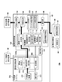
- FIG. 1 is a diagram illustrating a configuration of a medical examination support system 10 including an image management apparatus 100 according to the present embodiment.
- the medical examination support system 10 is a system for supporting examination work involving image photographing performed in a medical facility such as a hospital.
- a medical examination support system 10 including an endoscope apparatus as an example of an imaging apparatus that captures a medical examination image is shown.
- the medical examination support system 10 includes an endoscope system 20, an image management apparatus 100, and an image recording apparatus 40 that records image data of an examination image captured by the endoscope system 20 as an image file.
- 1 shows only one set of the endoscope system 20 and the image management apparatus 100, a plurality of the endoscope system 20 and the image management apparatus 100 may be provided.
- the endoscope system 20 and the image management apparatus 100 may be provided in a plurality of examination rooms in a medical facility, respectively.
- the image management apparatus 100 and the image recording apparatus 40 are communicably connected via a network 60 such as an intranet, a local area network (LAN), a wide area network (WAN), a virtual private network (VPN), or the Internet.
- a network 60 such as an intranet, a local area network (LAN), a wide area network (WAN), a virtual private network (VPN), or the Internet.
- the endoscope system 20 includes a type connected to the network 60 and a type not connected to the network 60.
- the endoscope system 20 and the image management apparatus 100 are directly connected by a cable or the like.
- the endoscope system 20 and the image management apparatus 100 may be connected by a plurality of cables.
- a video signal cable for transmitting a video signal from the endoscope system 20 to the image management apparatus 100
- the two control cables may be connected to a control signal cable for transmitting / receiving a control signal to / from each other.
- the endoscope system 20 includes an endoscope device 220, an operation unit 222, and an image processing device 200, and is connected to the live image display device 30.
- the endoscope apparatus 220 is inserted into a body cavity of a subject, takes an internal image with a solid-state imaging device such as a CCD at the tip, and outputs the captured image to the image processing apparatus 200 as an imaging signal.
- the operation unit 222 includes a switch, a keyboard, a pointing device such as a mouse and a trackball, a touch panel, a microphone, and the like, and is used to input instructions to the image processing apparatus 200 such as imaging start, imaging end, and imaging condition designation by the user. Used.
- the operation unit 222 may be integrated with the endoscope apparatus 220. A plurality of operation units 222 may be provided.
- the live image display device 30 receives a video signal captured by the endoscope device 220, processed and output by the image processing device 200, and displays it as a live image.
- the image processing apparatus 200 outputs a drive control signal for controlling the endoscope apparatus 220 to the endoscope apparatus 220.
- the image processing apparatus 200 also performs amplification, noise removal, analog / digital conversion, gain adjustment, brightness ratio adjustment, filter processing, and the like on the imaging signal input from the endoscope apparatus 220, and a solid-state imaging device Is generated as a live image, that is, a screen is generated.
- the image processing apparatus 200 does not have a network communication function, the image processing apparatus 200 is not connected to the network 60.
- these different types of image processing apparatuses are collectively referred to as “image processing apparatus 200”.
- the image recording device 40 transmits / receives data to / from other servers, systems, client terminals, and the like via a network, and an image storage unit 42 that stores, as an image file, photographs and moving images captured by the endoscope system 20 for recording. And a communication unit 44.
- the image management apparatus 100 includes a control unit 110, a device information storage unit 130, an image file generation unit 102, a temporary storage unit 106, a file processing unit 120, a screen generation unit 104, and a communication unit 108, and the recorded image display device 50. , And the operation unit 140.
- the device information storage unit 130 stores information regarding the image processing device 200. A specific example of information regarding the image processing apparatus 200 will be described later with reference to FIG.
- the control unit 110 includes a device identifier acquisition unit 112, an instruction reception unit 114, a device type acquisition unit 116, and an instruction unit 118.
- the apparatus identifier acquisition unit 112 is used when the image management apparatus 100 is connected to the image processing apparatus 200 or when the image management apparatus 100 is turned on while the image management apparatus 100 and the image processing apparatus 200 are connected. In addition, a device identifier for identifying the image processing device 200 is acquired from the image processing device 200. Then, the device identifier acquisition unit 112 records in the device information storage unit 130 that the image processing device 200 with the device identifier is being connected.
- the instruction receiving unit 114 receives instructions from the operation unit 140 and the image processing apparatus 200.
- the device type acquisition unit 116 refers to the device information storage unit 130 and reads the type of the connected image processing device 200.
- the instruction unit 118 transmits an instruction to the image file generation unit 102 and the file processing unit 120 based on the type of the connected image processing apparatus 200 read by the apparatus type acquisition unit 116.
- the image file generation unit 102 receives an instruction from the instruction unit 118 and receives it from the image processing apparatus 200 when the image processing apparatus 200 is an apparatus type that cannot directly transmit the image file to the image recording apparatus 40.
- the video signal is processed to generate an image file.
- the file processing unit 120 includes a file acquisition unit 122 and a file transfer unit 124.
- the file acquisition unit 122 receives an instruction from the instruction unit 118 and receives an instruction from the image recording apparatus 40 when the image processing apparatus 200 is an apparatus type that can directly transmit an image file to the image recording apparatus 40.
- the image file created by 200 is acquired.
- the file transfer unit 124 receives an instruction from the instruction unit 118 when the image processing apparatus 200 is an apparatus type that cannot directly transmit an image file to the image recording apparatus 40, and generates an image created by the image file generation unit 102.
- the file is transferred to the image recording device 40.
- the temporary storage unit 106 temporarily stores the image file generated by the image file generation unit 102 of the image management device 100 and the image file acquired by the file processing unit 120 from the image recording device 40.
- the screen generation unit 104 reads the image file generated by the image file generation unit 102 and the image file acquired by the file processing unit 120 from the image recording device 40 from the temporary storage unit 106, and displays, for example, an NTSC format or a PAL format.
- the image is converted into a video signal format to be displayed on the apparatus, and a screen to be displayed on the recorded image display apparatus 50 is generated.
- the communication unit 108 of the image management apparatus 100 transmits / receives data to / from other servers, systems, client terminals, etc. via the network.
- the recorded image display device 50 receives an image captured by the endoscope device 220 and recorded in the image recording device 40 from the screen generation unit 104 of the image management device 100 and displays it.
- the operation unit 140 includes a switch, a keyboard, a pointing device such as a mouse and a trackball, a touch panel, a microphone, and the like. The user starts an imaging start instruction, an imaging end instruction, an imaging condition designation, an image display instruction, an interpretation report, and a chart entry. Used for input.
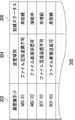
- FIG. 2 is a diagram illustrating an example of the device information table 300 stored in the device information storage unit 130.
- the device information table 300 includes a device identifier column 302, a device type column 304, and a device connection status column 306.
- the device identifier column 302 an identifier for identifying each device is described.
- the device identifier may be an identifier that uniquely identifies each image processing device 200, or may be an identifier that identifies the type of the image processing device 200, such as a model number of the image processing device 200.
- the type of the image processing device 200 indicating whether or not each image processing device 200 is a type of device that can directly transmit an image file to the image recording device 40 is described.
- the apparatus connection status column 306 a connection status indicating whether each image processing apparatus 200 is currently connected to the image management apparatus 100 is described.
- the device identifier column 302 and the device type column 304 reflect, for example, the product status at the time of shipment of the image management apparatus 100 in advance, respectively in the device identifier column 302 and the device type column 304. Described.
- the device identifier column 302 and the device type column 304 may be set to be updated online as needed when a new image processing device 200 is released.
- the control unit 110 of the image management apparatus 100 acquires information distributed from a manufacturer or the like via the network, and describes information about the new image processing apparatus 200 in the apparatus identifier field 302 and the apparatus type field 304. May be. Thereby, it is possible to save the user from setting and registering the new image processing apparatus 200 released after purchasing the image management apparatus 100.
- the device identifier column 302 and the device type column 304 may be set so that the user can input them. Thereby, the user can freely set the path for recording the image file, reflecting the network situation of each medical facility, the usage method of the inspection device, and the like.
- the apparatus identifier acquisition unit 112 supplies power to the image management apparatus 100 when the image management apparatus 100 is connected to the image processing apparatus 200 or in a state where the image management apparatus 100 and the image processing apparatus 200 are connected.
- the device identifier of the image processing device 200 is acquired from the image processing device 200.
- the apparatus identifier acquisition unit 112 may acquire the apparatus identifier by sending an inquiry to the image processing apparatus 200 and obtaining a response. Alternatively, it may be acquired by receiving device identifier information transmitted from the image processing device 200 at a timing when the image management device 100 and the image processing device 200 are connected, or at a certain time interval.
- the device identifier acquisition unit 112 changes the device connection status column 306 corresponding to the acquired device identifier to the “connected” status.
- the device identifier acquisition unit 112 also sets the device connection status column 306 for a device that cannot be detected to be connected when the device connection status column 306 of the device information table 300 is in the “connected” status. Change to "Not Connected" status.
- the device type acquisition unit 116 refers to the device information table 300 stored in the device information storage unit 130 when the instruction receiving unit 114 receives a still image capturing instruction from the image processing device 200, and the image management device 100.
- the type of the image processing apparatus 200 connected to is read.
- the device type acquisition unit 116 refers to the device type column 304 of the device in which the device connection status column 306 of the device information table 300 is in the “connected” status. Then, it is determined whether or not the type of the connected image processing apparatus 200 is a type of apparatus that can directly transmit the image file to the image recording apparatus 40 and record it.
- FIGS. 3 and 4 illustrate image files recorded in different routes in the medical examination support system 10 according to the present embodiment, depending on the type of the image processing apparatus 200 and the still image / moving image of the imaging instruction.
- FIG. 10 is a diagram for explaining how a recorded image file is displayed on a recorded image display device 50.
- FIG. 3 illustrates the configuration of the medical examination support system 10a when an image processing apparatus 200a of a type that cannot directly transmit an image file to the image recording apparatus 40 and the image management apparatus 100 according to the present embodiment are connected.
- FIG. The configuration and operation of the elements denoted by the same reference numerals as those in FIG. 1 are the same as those shown in FIG.
- the image processing device 200a of the endoscope system 20a includes a video signal generation unit 204, a screen generation unit 202, and a control unit 208.
- the control unit 208 Upon receiving an instruction from the operation unit 222 of the endoscope system 20a or the control unit 110 of the image management apparatus 100, the control unit 208 outputs a drive control signal for controlling the endoscope apparatus 220 or the image management apparatus.
- the apparatus identifier of the image processing apparatus 200a is transmitted to the control unit 110 of 100.
- the video signal generation unit 204 of the image processing apparatus 200a performs amplification, noise removal, analog / digital conversion, gain adjustment, brightness ratio adjustment, filter processing, and the like on the imaging signal input from the endoscope apparatus 220. Are converted into video signals and output to the screen generation unit 202 and the image management apparatus 100 of the image processing apparatus 200a.
- the screen generation unit 202 of the image processing apparatus 200a converts the video signal input from the video signal generation unit 204 into a video signal in a format for display on a display device such as an NTSC format or a PAL format, and displays a live image A screen to be displayed on the display device 30 is generated and output to the live image display device 30.
- the apparatus type acquisition unit 116 of the image management apparatus 100 stores the apparatus information storage unit 130 as described above with reference to FIGS. 1 and 2 when the instruction reception unit 114 receives a still image capturing instruction from the image processing apparatus 200a.
- the type of the image processing apparatus 200a connected to the image management apparatus 100 is read with reference to the stored apparatus information table 300.
- the device type acquisition unit 116 is an image processing device of a type in which the type of the connected image processing device 200a cannot directly transmit the image file to the image recording device 40 for recording. It is determined that there is, and the determination result is transmitted to the instruction unit 118.
- the instruction unit 118 sends an image file generation instruction to the image file generation unit 102 of the image management apparatus 100, and the image file generation unit 102 processes the video signal received from the image processing apparatus 200 to generate an image file.
- the image file can be created in, for example, a JPEG format, a GIF format, or a TIFF format.
- the image file is not limited to this, and has a size that can be transmitted via a network and can be stored in the image storage unit 42. If it exists, it may be created in any format.
- the image file generation unit 102 stores the generated image file in the temporary storage unit 106.
- the file transfer unit 124 transfers the image file created by the image file generation unit 102 and stored in the temporary storage unit 106 to the image recording device 40 for storage in the image storage unit 42 of the image recording device 40.
- the screen generation unit 104 of the image management device 100 converts the image file created by the image file generation unit 102 of the image management device 100 and stored in the temporary storage unit 106 into a video signal for display on the recorded image display device 50. Then, a screen is generated and output to the recorded image display device 50. Thereby, the image file captured by the endoscope apparatus 220 and created by the image management apparatus 100 can be stored in the image storage unit 42 of the image recording apparatus 40 and displayed on the recorded image display apparatus 50. Can do.
- the instruction receiving unit 114 receives an instruction to capture a moving image
- the device type acquisition unit 116 of the image management device 100 does not read out the type of the connected image processing device 200a, but performs image management.
- An image file generation instruction is sent to the image file generation unit 102 of the apparatus 100. Subsequently, a moving image file is generated, stored, and displayed by an operation similar to the operation described in relation to the still image.
- the image file generation unit 102 processes the video signal transmitted from the image processing apparatus 200 to create a moving image file, and stores it in the temporary storage unit 106.
- the file transfer unit 124 transfers the moving image file created by the image file generation unit 102 and stored in the temporary storage unit 106 to the image recording device 40 for storage in the image storage unit 42 of the image recording device 40.
- the screen generation unit 104 of the image management apparatus 100 converts the moving image file created by the image file generation unit 102 of the image management apparatus 100 and stored in the temporary storage unit 106 into a video signal for display on the recorded image display apparatus 50. The screen is generated by conversion, and is output to the recorded image display device 50.
- the image management apparatus 100 when recording a moving image, the image management apparatus 100 always creates an image file regardless of the type of the image processing apparatus 200, and the image created by the image management apparatus 100 is stored in the image storage device 40. It can be stored in the unit 42. In addition, the image created by the image management apparatus 100 can be displayed on the recorded image display apparatus 50.
- a network can be efficiently constructed in advance by considering the network load by always keeping the transfer path of the image file constant. Therefore, it is possible to avoid a situation in which the network is congested because the moving image is sent.
- FIG. 4 illustrates the configuration of the medical examination support system 10b when the image processing apparatus 200b of a type capable of directly recording an image file in the image recording apparatus 40 and the image management apparatus 100 according to the present embodiment are connected. It is a figure for doing.
- the configuration and operation of the elements denoted by the same reference numerals as those in FIG. 1 or FIG. 3 are the same as the elements shown in FIG. 1 or FIG.
- the image processing apparatus 200b of the endoscope system 20b further includes an image file generation unit 206 and a communication unit 210 in addition to the components shown in FIG.
- the image file generation unit 206 of the image processing apparatus 200b processes the video signal transmitted from the video signal generation unit 204 to create an image file. Then, the control unit 208 of the image processing apparatus 200 stores the image file created by the image file generation unit 206 in the image storage unit 42 of the image recording apparatus 40, the communication unit 210 of the image processing apparatus 200b, the network 60, And it transmits to the image memory
- the device type acquisition unit 116 of the image management device 100 stores the device information according to the procedure described above with reference to FIGS. 1 and 2 when the instruction receiving unit 114 receives a still image capturing instruction from the image processing device 200b.
- the type of the connected image processing apparatus 200 is read with reference to the apparatus information table 300 of the unit 130.
- the device type acquisition unit 116 indicates that the type of the connected image processing device 200b is a device type that can directly transmit an image file to the image recording device 40 for recording.
- the determination result is transmitted to the instruction unit 118.
- the instruction unit 118 sends an instruction not to generate an image file to the image file generation unit 102 of the image management apparatus 100. Even when the image file generation unit 102 of the image management apparatus 100 receives a video signal from the video signal generation unit 204 of the image processing apparatus 200b, the image file generation unit 102 does not generate an image file.
- the instruction unit 118 also sends an image file acquisition instruction to the file acquisition unit 122, and the file acquisition unit 122 transmits the image directly transmitted from the image processing apparatus 200 b to the image recording apparatus 40 and stored in the image storage unit 42. The file is read from the image storage unit 42 of the image recording device 40.
- the file acquisition unit 122 first checks whether the image file created by the image processing apparatus 200b is stored in the image storage unit. Specifically, the file acquisition unit 122 searches the image storage unit 42 of the image recording device 40, transmits an inquiry to the image recording device 40, acquires a response, or is transmitted from the image recording device 40. Receive file creation information. Thus, the file acquisition unit 122 determines whether the image file created by the image processing device 200 is stored in the image storage unit 42 of the image recording device 40, and the image processing device 200 creates the image storage unit 42. If the processed image file is stored, the image file is acquired and stored in the temporary storage unit 106.
- the screen generation unit 104 of the image management device 100 generates a screen by converting the image file acquired by the file acquisition unit 122 and stored in the temporary storage unit 106 into a video signal for display on the recorded image display device 50. And output to the recorded image display device 50. As a result, the image captured by the endoscope device 220 and stored in the image recording device 40 can be displayed on the recorded image display device 50. Further, when the type of the image processing apparatus 200 is an apparatus type that can create an image file and directly transmit it to the recording apparatus, the image processing apparatus 200b and the image management apparatus 100 are both image files. It is possible to avoid waste and confusion caused by creating and storing twice in the recording device.
- the instruction receiving unit 114 receives a moving image capturing instruction from the image processing device 200b
- the device type acquisition unit 116 of the image management device 100 does not read out the type of the connected device, and An image file generation instruction is sent to the image file generation unit 102 of the management apparatus 100.
- the image management apparatus 100 generates an image file, and the generated image file is stored in the image recording apparatus 40 and displayed on the recorded image display apparatus 50 through operations similar to those described above with reference to FIG. A screen is generated to
- the image management apparatus 100 when recording a moving image, the image management apparatus 100 always creates an image file regardless of the type of the image processing apparatus 200, and stores the image created by the image management apparatus 100 in the image recording apparatus 40. be able to. In addition, the image created by the image management apparatus 100 can be displayed on the recorded image display apparatus 50.
- a network can be efficiently constructed in advance by considering the network load by always keeping the transfer path of the image file constant. Therefore, it is possible to avoid a situation in which the network is congested because the moving image is sent.
- the video signal transmitted from the video signal generation unit 204 of the image processing apparatus 200 is directly input to the screen generation unit 104 of the image management apparatus 100 and recorded. It may be displayed on the image display device 50.
- the recorded image display device 50 can also display the image captured by the endoscope camera during the examination as a live video.
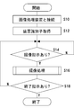
- FIG. 5 shows that when an examination is performed using the endoscope apparatus 220, the image taken by the endoscope apparatus 220 is recorded in the image storage unit 42 and displayed on the recorded image display apparatus 50 in the image management apparatus 100. It is a flowchart which shows the procedure of the process to perform.
- a user connects the image processing apparatus 200 and the image management apparatus 100 with a cable or the like, or turns on the image management apparatus 100 in a state where the image processing apparatus 200 and the image management apparatus 100 are connected ( S10).
- the device identifier acquisition unit 112 of the image management device 100 acquires the device identifier of the image processing device 200 (S12), and stores it in the device information storage unit 130 as information on the connected device.
- the image management apparatus 100 stands by without performing an imaging process.
- the instruction reception unit 114 of the image management apparatus 100 receives the instruction (S14). Y), an imaging process is performed (S16).
- an imaging process is executed every time an imaging instruction is received (S16), and when the instruction receiving unit 114 of the image management apparatus 100 receives an imaging end instruction (Y in S18). The inspection is finished.
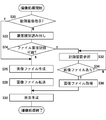
- FIG. 6 is a flowchart showing the procedure of the imaging process of FIG.
- the apparatus type acquisition unit 116 transmits the apparatus identifier of the connected image processing apparatus 200 from the apparatus information storage unit 130. And the type of the connected image processing apparatus 200 is read based on the read apparatus identifier (S22).
- the image file generation unit 102 Processes the video signal transmitted from the image processing apparatus 200 to create an image file (S26), and stores it in the temporary storage unit.
- the file transfer unit 124 transfers the still image file created by the image file generation unit 102 and stored in the temporary storage unit 106 to the image recording device 40 in order to store it in the image storage unit 42 of the image recording device 40 ( S28).
- the screen generation unit 104 of the image management device 100 generates a screen for displaying the image file created by the image file generation unit 102 and stored in the temporary storage unit 106 (S30), and outputs the screen to the recorded image display device 50. .
- the display screen generation process of step 30 is performed after the image file transfer process of step 28, but actually, these may be processed in parallel. Further, the display screen generation process in step 30 may be executed prior to the image file transfer process in step 28.
- the image file generation unit 102 Does not create an image file from the video signal transmitted from the image processing apparatus 200.
- the file acquisition unit 122 refers to the inside of the image storage unit 42, confirms whether the image processing apparatus 200 has created an image file and stored it in the image storage unit 42 (S32), and creates it in the image storage unit 42. If the processed image file is not stored (N in S34), the process waits. If the created image file has been stored (Y in S34), the file acquisition unit 122 acquires the image file created by the image processing apparatus 200 and stored in the image storage unit 42 (S36). Then, the screen generation unit 104 of the image management apparatus 100 generates a screen for displaying the image file created by the image processing apparatus 200 (S30) and displays the screen on the recorded image display apparatus 50.
- the image file generation unit 102 determines whether the image processing apparatus 200 is connected, regardless of the type of the connected image processing apparatus 200.
- the video signal transmitted from 200 is processed to create a moving image file (S26) and stored in the temporary storage unit 106.
- the file transfer unit 124 transfers the moving image file created by the image file generation unit 102 and stored in the temporary storage unit 106 to the image storage unit 42 of the image recording device 40 (S28).
- the screen generation unit 104 of the image management apparatus 100 generates a screen for displaying the moving image file created by the image file generation unit 102 (S30) and displays it on the recorded image display apparatus 50.
- the user can efficiently record the medical examination image without being aware of the difference in the model number of the medical examination equipment.
- the image management apparatus 100 when the communication unit 108 of the image management apparatus 100 detects that the image processing apparatus 200 is not connected to the network 60, the type of the image processing apparatus 200 and the moving image / still image of the imaging instruction Regardless of the case, the image management apparatus 100 generates an image file.
- the configuration and operation of the image management apparatus 100 according to the modification are also the same as those of the image management apparatus 100 of FIGS. 1, 3, and 4, and will be described below with a focus on differences from the above-described embodiment.
- the image management apparatus 100 according to the modified example when the communication unit 108 of the image management apparatus 100 detects that the image processing apparatus 200 connected to the image management apparatus 100 is not connected to the network 60, the instruction unit 118.
- the device information table 300 stored in the device information storage unit 130 the network status column (not shown) corresponding to the image processing device 200 whose connection status is “connected” indicates that network connection is not possible. Describe.
- the instruction receiving unit 114 receives an imaging instruction from the image processing device 200
- the device type acquisition unit 116 refers to the network status column of the connected device, and when the network connection is impossible, the device type is not read out. .
- the instruction unit 118 sends an image file generation instruction to the image file generation unit 102 of the image management apparatus 100.
- the image file generation unit 102 processes the video signal transmitted from the image processing apparatus 200 to create a moving image file, and stores it in the temporary storage unit 106.
- the instruction unit 118 issues a file transfer instruction to the file transfer unit 124, and the file transfer unit 124 generates the image file generated by the image file generation unit 102 and stored in the temporary storage unit 106. Then, the image data is transferred to the image recording device 40 for storage in the image recording device 40.
- the screen generation unit 104 of the image management device 100 converts the image file stored in the temporary storage unit 106 into a video signal in a format for display on the recorded image display device 50 to generate a screen, and the recorded image Output to the display device 50.
- the image management apparatus 100 always creates an image file regardless of the type of the image processing apparatus 200 or the still image / moving image. Then, it can be transferred to the image recording apparatus 40.
- the image management apparatus 100 As in this modification, the configuration and operation of the image management apparatus 100 according to this modification are also the same as those of the image management apparatus 100 of FIGS. 1, 3, and 4, and will be described below with a focus on differences from the above-described embodiment.
- the image file generation unit 102 of the image management apparatus 100 always generates an image file and stores it in the temporary storage unit 106 regardless of the type of the image processing apparatus 200. Discard the image file later.
- the instruction accepting unit 114 accepts an imaging instruction such as an imaging start instruction and an imaging end instruction from the image processing apparatus 200.
- an imaging instruction such as an imaging start instruction and an imaging end instruction from the image processing apparatus 200.
- information on the time when the instruction is issued is attached to these imaging instructions.
- imaging time information is also attached to an image file created by the image management apparatus 100 or the image processing apparatus 200.
- the type of the image processing apparatus 200 connected to the image management apparatus 100 transmits the image file directly to the image recording apparatus 40 and records it, as in the image processing apparatus 200b shown in FIG. Even if it is a type of apparatus that can be used, an image file is once created in the image management apparatus 100.
- the instruction receiving unit 114 receives an imaging instruction
- the instruction unit 118 always issues an image file generation instruction to the image file generation unit 102 of the image management apparatus 100 regardless of the type of the image processing apparatus 200. send.
- the image file generation unit 102 processes the video signal received from the image processing apparatus 200, creates an image file, and stores the image file in the temporary storage unit 106.
- the instruction unit 118 sends an image file acquisition instruction that instructs the file acquisition unit 122 to acquire the image file created by the image processing device 200b from the image recording device 40.
- the instruction unit 118 further discards the image file created by the image file generation unit 102 and stored in the temporary storage unit 106 when the file acquisition unit 122 can acquire the image file. Sends an image file discard instruction instructing to do so.
- the file acquisition unit 122 acquires the image file and stores it in the temporary storage unit 106. At this time, the file acquisition unit 122 stores the image file stored in the temporary storage unit 106 in the temporary storage unit 106 when there is an image file having the same imaging time as the image file acquired by the file acquisition unit 122. Discard that image file.
- the file acquisition unit 122 acquires the image file stored in the image storage unit 42 of the image recording device 40 even after a predetermined file acquisition reference time has elapsed after receiving the image file acquisition instruction from the instruction unit 118.
- the file acquisition unit 122 does not delete the image file in the temporary storage unit 106.
- the file acquisition unit 122 reports to the instruction unit 118 that the image file could not be acquired.
- the instruction unit 118 issues a file transfer instruction to the file transfer unit 124.
- the file transfer unit 124 creates the image file generation unit 102 and stores the image file stored in the temporary storage unit 106 in the image storage unit 42 of the image recording device 40. Forward to.
- the predetermined file acquisition reference time is a time used as a threshold when determining whether to take another means when a file cannot be acquired, or based on the time that has elapsed without acquiring a file. .
- the predetermined file acquisition reference time is, for example, when the imaging instruction is issued in the medical examination support system 10 and the control unit 208 of the image processing apparatus 200 receives the imaging instruction. It is determined as a time obtained by adding an allowable delay time to an average required time until the data is stored in the memory.
- the predetermined file acquisition reference time may be determined experimentally or empirically, and may be configured so that the user can set it in consideration of the circumstances of each individual medical facility.
- the screen generation unit 104 of the image management device 100 converts the image file stored in the temporary storage unit 106 into a video signal in a format for display on the recorded image display device 50 to generate a screen, and the recorded image display device Output to 50.
- the image management apparatus 200 Even when some trouble occurs and the image processing apparatus 200 cannot create an image file, or even when the created image file cannot be recorded in the image storage unit 42, the image management apparatus An image file created by 100 and temporarily stored can be used as a recording file. Therefore, a more reliable image management apparatus can be provided. In addition, since the image could not be recorded, it is possible to prevent a situation such as extending the inspection time, taking a picture again, or performing a re-inspection.
- the present invention provides, as an image processing apparatus, an apparatus capable of creating an image file for electronic recording on a recording apparatus and transmitting the image file directly to the recording apparatus, and an image that cannot generate an image file and transmit the image file directly to the recording apparatus. It can be applied when processing devices are used together.
- the present invention can be applied to management of medical image data such as X-rays, CT, MRI, and echoes, and waveform data such as an electrocardiogram.
- the present invention can be used for an image management apparatus for processing an image captured by a medical examination device.
- image recording devices 44 communication units, 60 networks, 100 image management devices, 102 image file generation units, 104 screen generation units, 108 communication units, 110 control units, 112 device identifier acquisition units, 114 instruction reception units, 116 device types Acquisition unit, 118 instruction unit, 120 file processing unit, 122 file acquisition unit, 124 file transfer unit, 130 device information storage unit, 200 image processing device, 202 screen generation unit, 206 image file generation unit, 210 communication unit, within 220 Endoscopic device.
Abstract
Description
この医用画像システムでは、通常は、モダリティにより生成された医用画像データを検像装置に送信し、検像装置において検像処理を行い、検像処理後の医用画像データを画像保存通信システムにより保存し、管理する。一方、検像装置が故障などにより検像処理を実施不可能な場合には、モダリティから直接画像保存通信システムに対して医用画像データを送信し、検像処理を実施していない状態で医用画像データを保存する。
この内視鏡システムにおいては、撮像した被写体の像を撮像信号として出力する内視鏡と、プリンタなどの静止画像保存装置とが、プロセッサを介して接続される。プロセッサは、内視鏡が出力した撮像信号に信号処理を行い、映像信号として、プリンタなどの静止画像保存装置に出力する。プロセッサは、例えばプリンタがビジー状態であることを検知したような場合、信号処理を行った映像信号を、PCカードなどの画像データ保存装置に出力する制御を行う。
この内視鏡システムにおいては、内視鏡装置によって各検査現場にて画像を撮像し、管理センタの撮像画像管理コンピュータを配布先として、撮像画像を直接電子メールで送信する。管理センタの撮像画像管理コンピュータは、各内視鏡装置からの撮像画像を電子メールで受信し、集中管理する。
したがって、たいていの医療機関では、異なる種類あるいは世代の撮像装置や画像処理装置が併存する環境の中で、検査が行われている。
このため撮像装置や画像処理装置を用いる検査において、これらの装置の操作を効率的に行うことが求められている。
内視鏡検査や超音波検査などの、検査すべき範囲が、撮像装置による1回の撮像範囲よりも広範囲に及ぶような医療検査においては、一般的に、医師や検査技師等が、カメラやプローブが捉えている画像をライブ映像として観察しながら、内視鏡スコープやプローブなどを少しずつ移動させて、検査をすすめる。
そして、異常部位を発見した個所や、あらかじめ検査オーダ等で指定されている個所において、検査の記録として静止画や、動画を保存する。
この際、ユーザは、記録させた各画像について、きちんと撮像できているか否か、その場で表示させて確認し、必要な場合には、再度撮像を行う。
また、本発明の実施例にかかる画像管理装置は、画像処理装置の種別によって、画像ファイルを作成する装置や、画像ファイルを転送する経路が異なる場合であっても、記録した画像ファイルを自動的に記録画像確認用モニタに表示させることができる。
これにより、ユーザは、画像処理装置の種類の違いを意識することなく撮像指示を出し、また撮像した画像の確認を行うことができるため、医師や検査技師などのユーザが、本来の業務に関連のないことで時間をとられたり、検査および観察に費やされる時間が長時間化するといった事態を防ぐことができる。
医療検査支援システム10は、病院などの医療施設内において行われる画像撮影を伴う検査業務を支援するためのシステムである。なお、本実施例においては、医療検査画像を撮影する撮像装置の一例としての内視鏡装置を含む医療検査支援システム10の例を示す。
なお、図1には、一組の内視鏡システム20および画像管理装置100のみ示しているが、内視鏡システム20、および、画像管理装置100は、複数個備えられてもよい。例えば、医療施設内の複数の検査室に、それぞれ内視鏡システム20および画像管理装置100が備えられてもよい。
なお、後述するように、内視鏡システム20には、ネットワーク60に接続されるタイプのものと、ネットワーク60に接続されないタイプのものとがある。
内視鏡装置220は、被検者の体腔内に挿入され、先端のCCDなどの固体撮像素子により内部の画像を撮像し、撮像した像を撮像信号として画像処理装置200に出力する。
ライブ画像表示装置30は、内視鏡装置220が撮像し、画像処理装置200が処理して出力する映像信号を受信し、ライブ画像として表示する。
一方、自ら画像ファイルを作成してネットワークを介して送信することができない種別の画像処理装置200もある。画像処理装置200がネットワーク通信機能をもたない場合、画像処理装置200は、ネットワーク60には接続されない。
本明細書においては、これらの異なる種類の画像処理装置を総称して、「画像処理装置200」という。
制御部110は、装置識別子取得部112、指示受付部114、装置種別取得部116、および、指示部118を備える。
装置種別取得部116は、指示受付部114が撮像指示を受け付けたときに、装置情報記憶部130を参照して、接続中の画像処理装置200の種別を読み出す。
ファイル取得部122は、画像処理装置200が、画像ファイルを直接、画像記録装置40に送信できる装置種別である場合に、指示部118からの指示を受けて、画像記録装置40から、画像処理装置200が作成した画像ファイルを取得する。
ファイル転送部124は、画像処理装置200が、画像ファイルを直接、画像記録装置40に送信できない装置種別である場合に、指示部118からの指示を受けて、画像ファイル生成部102が作成した画像ファイルを画像記録装置40に転送する。
画面生成部104は、画像ファイル生成部102が生成した画像ファイルや、ファイル処理部120が画像記録装置40から取得した画像ファイルを、一時記憶部106から読み出し、例えばNTSC形式やPAL形式などの表示装置に表示させるための映像信号の形式に変換し、記録画像表示装置50に表示させるための画面を生成する。
操作部140は、スイッチや、キーボード、マウスやトラックボールなどのポインティングデバイス、タッチパネル、マイクロフォンなどで構成され、ユーザによる撮像開始指示、撮像終了指示、撮像条件指定、画像表示指示、読影レポートやカルテ記入などの入力のために用いられる。
装置種別欄304には、各画像処理装置200について、画像ファイルを直接、画像記録装置40に送信可能なタイプの装置であるか否かを示す画像処理装置200の種別が記述される。
装置接続ステータス欄306には、各画像処理装置200が、現在、画像管理装置100と接続されているか否かを示す接続ステータスが記述される。
装置識別子取得部112は、装置識別子を、画像処理装置200に問い合わせを送り、応答を得ることで取得してもよい。あるいは、画像管理装置100と画像処理装置200とが接続されたタイミングや、一定時間間隔等のタイミングで画像処理装置200から送信される装置識別子情報を受信することで取得してもよい。
装置識別子取得部112はまた、接続されていることが検出できない装置について、装置情報テーブル300の装置接続ステータス欄306欄が「接続中」ステータスになっている場合は、その装置接続ステータス欄306を「未接続」ステータスに変更する。
具体的には、装置種別取得部116は、装置情報テーブル300の装置接続ステータス欄306が「接続中」ステータスである装置の装置種別欄304を参照する。そして、接続されている画像処理装置200の種別が、画像ファイルを直接、画像記録装置40に送信して記録させることができる種別の装置であるか否か、判定する。
制御部208は、内視鏡システム20aの操作部222や画像管理装置100の制御部110から指示を受けつけると、内視鏡装置220を制御するための駆動制御信号を出力したり、画像管理装置100の制御部110に、画像処理装置200aの装置識別子を送信したりする。
画像処理装置200aの画面生成部202は、映像信号生成部204から入力された映像信号を、例えばNTSC形式やPAL形式などの表示装置に表示させるための形式の映像信号に変換して、ライブ画像表示装置30に表示させるための画面を生成し、ライブ画像表示装置30に出力する。
図3の構成の場合、装置種別取得部116は、接続されている画像処理装置200aの種別が、画像ファイルを直接、画像記録装置40に送信して記録させることができない種別の画像処理装置であることを判定し、指示部118に、判定結果を送信する。
画像ファイルは、例えば、JPEG形式、GIF形式またはTIFF形式等で作成されうるが、これに限られるものではなく、ネットワークを介して送信可能なサイズであり、画像記憶部42に格納可能な形式であれば、任意の形式で作成されてよい。
画像ファイル生成部102は、生成した画像ファイルを、一時記憶部106に格納する。
これにより、内視鏡装置220が撮像し、画像管理装置100が作成した画像ファイルを、画像記録装置40の画像記憶部42に格納することができ、また、記録画像表示装置50に表示させることができる。
そして、以下、静止画像に関連して説明した動作と同様の動作により、動画像ファイルが生成され、格納され、また表示される。
画像管理装置100の画面生成部104は、画像管理装置100の画像ファイル生成部102が作成し、一時記憶部106に格納した動画像ファイルを、記録画像表示装置50に表示させるために映像信号に変換して、画面を生成し、記録画像表示装置50に出力する。
このように、一般的にファイルサイズが大きい動画の場合に画像ファイルの転送経路を常に一定にすることで、あらかじめ、ネットワーク負荷を考慮して効率的にネットワークを構築することができる。よって、動画を送ったためにネットワークが輻輳するような事態を避けることができる。
そして、画像処理装置200の制御部208は、画像ファイル生成部206が作成した画像ファイルを画像記録装置40の画像記憶部42に格納させるために、画像処理装置200bの通信部210、ネットワーク60、および、画像記録装置40の通信部44を介して、画像記憶部42に送信する。
図4の構成の場合、装置種別取得部116は、接続されている画像処理装置200bの種別が、画像ファイルを、直接、画像記録装置40に送信して記録させることができる装置種別であると判定し、指示部118に、判定結果を送信する。
指示部118はまた、ファイル取得部122に、画像ファイル取得指示を送り、ファイル取得部122は、画像処理装置200bから、直接、画像記録装置40に送信され、画像記憶部42に格納された画像ファイルを、画像記録装置40の画像記憶部42から読み出す。
これにより、内視鏡装置220が撮像し、画像記録装置40に格納される画像を、記録画像表示装置50に表示させることができる。また、画像処理装置200の種別が、画像ファイルを作成して、記録装置に直接送信することができる装置種別である場合に、画像処理装置200bと画像管理装置100とが、双方とも、画像ファイルを作成して、記録装置に二重に格納してしまうことによる無駄や混乱を避けることができる。
このように、一般的にファイルサイズが大きい動画の場合に画像ファイルの転送経路を常に一定にすることで、あらかじめ、ネットワーク負荷を考慮して効率的にネットワークを構築することができる。したがって、動画を送ったためにネットワークが輻輳するような事態を避けることができる。
図5は、内視鏡装置220を用いて検査を行う際に、画像管理装置100において、内視鏡装置220で撮影した画像を画像記憶部42に記録し、また記録画像表示装置50に表示させる処理の手順を示すフローチャートである。
指示受付部114が受け付けた撮像指示が、静止画の撮像指示である場合(S20のN)、装置種別取得部116は、装置情報記憶部130から、接続されている画像処理装置200の装置識別子を読み出し、読み出した装置識別子にもとづいて、接続されている画像処理装置200の種別を読み出す(S22)。
この変形例においては、画像管理装置100の通信部108が、画像処理装置200がネットワーク60に接続されていないことを検知した場合に、画像処理装置200の種別や、撮像指示の動画/静止画の別にかかわらず、画像管理装置100が画像ファイルを生成する。
変形例にかかる画像管理装置100において、画像管理装置100の通信部108が、画像管理装置100と接続される画像処理装置200がネットワーク60に接続されていないことを検知した場合に、指示部118は、装置情報記憶部130に格納される装置情報テーブル300において、接続ステータスが「接続中」である画像処理装置200に対応するネットワークステータス欄(図示せず)に、ネットワーク接続不可であることを記述する。
すなわち、画像ファイル生成部102は、画像処理装置200から送信された映像信号を処理して動画像ファイルを作成し、一時記憶部106に格納する。指示部118は、ファイル転送部124に、ファイル転送指示を出し、ファイル転送部124は、画像ファイル生成部102が作成し、一時記憶部106に格納した画像ファイルを画像記録装置40の画像記憶部42に格納させるために画像記録装置40に転送する。
そして、画像管理装置100の画面生成部104は、一時記憶部106に格納される画像ファイルを、記録画像表示装置50に表示させるための形式の映像信号に変換して画面を生成し、記録画像表示装置50に出力する。
この変形例にかかる画像管理装置100の構成および動作も、図1、図3、および、図4の画像管理装置100と同様であり、以下、前述の実施例との相違点を中心に説明する。
この変形例においては、画像管理装置100の画像ファイル生成部102は、画像処理装置200の種別にかかわらず、常に、画像ファイルを生成して、一時記憶部106に格納し、不要な場合には、後から画像ファイルを廃棄する。
具体的には、指示受付部114が撮像指示を受けた場合、指示部118は、像処理装置200の種別にかかわらず、常に、画像管理装置100の画像ファイル生成部102に画像ファイル生成指示を送る。画像ファイル生成部102は、画像処理装置200から受信した映像信号を処理して、画像ファイルを作成し、一時記憶部106に格納する。
本変形例において、指示部118は、さらに、ファイル取得部122に、画像ファイルを取得することができた場合に、画像ファイル生成部102が作成して一時記憶部106に格納した画像ファイルを廃棄するよう指示する画像ファイル廃棄指示を送る。
この際、ファイル取得部122は、一時記憶部106に格納されている画像ファイルのうち、ファイル取得部122が取得した画像ファイルと撮像時刻が同じ画像ファイルがある場合、一時記憶部106に格納されていたその画像ファイルを廃棄する。
所定のファイル取得基準時間は、例えば、その医療検査支援システム10において、撮像指示が出され、画像処理装置200の制御部208が撮影指示を受け付けてから、撮像された画像ファイルが画像記憶部42に格納されるまでの間の平均的な所要時間に、許容可能な遅延時間を加えた時間として定める。所定のファイル取得基準時間は、実験により、または経験的に定めてよく、また、個々の医療施設ごとの事情を加味して、ユーザが設定することができる構成としてもよい。
また、当業者の知識に基づいて各種の設計変更等の変形を実施形態に対して加えることも可能であり、そのような変形が加えられた実施形態も本発明の範囲に含まれうる。
Claims (6)
- 医療検査画像を撮影する撮像装置から撮像信号を受信する画像処理装置と、撮影した画像を記録する画像記録装置と、に接続される画像管理装置であって、
2以上の画像処理装置について、画像処理装置識別子と、その画像処理装置が画像ファイルを直接、画像記録装置に送信可能な画像処理装置であるか否かを示す画像処理装置種別とを関連づけて記憶する装置情報記憶部と、
前記接続される画像処理装置から画像処理装置識別子を取得する装置識別子取得部と、
前記取得部が取得した画像処理装置識別子にもとづいて前記装置情報記憶部を参照し、前記接続される画像処理装置の画像処理装置種別を読み出す装置種別取得部と、
前記装置種別取得部が読み出した画像処理装置種別が、画像ファイルを直接、画像記録装置に送信可能であることを示す場合に、前記画像処理装置が直接、前記画像処理装置に記録した画像ファイルを、前記画像記録装置から読み出す画像ファイル取得部と、
前記装置種別取得部が読み出した画像処理装置種別が、画像ファイルを直接、画像記録装置に送信不可能であることを示す場合に、前記画像処理装置から送信された映像信号を処理して画像ファイルを作成する画像ファイル生成部と、
前記画像ファイル生成部が作成した画像ファイルを前記画像記録装置に格納させるために前記画像記録装置に転送する画像ファイル転送部と、
前記画像ファイル生成部が作成した画像ファイル、または、前記画像ファイル取得部が取得した画像ファイルを表示装置に表示させるための画面を生成する画面生成部と、
を備えることを特徴とする画像管理装置。 - 撮像指示を受け付ける指示受付部をさらに備え、
前記装置種別取得部は、前記指示受付部が静止画の撮像指示を受け付けた場合に、前記装置情報記憶部を参照し、前記接続される画像処理装置の画像処理装置種別を読み出し、
前記画像ファイル生成部は、前記装置種別取得部が読み出した画像処理装置種別が、画像ファイルを直接、画像記録装置に送信可能であることを示す場合に、前記画像処理装置から送信された映像信号から画像ファイルを作成しないことを特徴とする請求項1に記載の画像管理装置。 - 前記指示受付部が、動画の撮像指示を受け付けた場合に、
前記画像ファイル生成部は、前記画像処理装置から送信された映像信号を処理して画像ファイルを作成し、
前記画像ファイル転送部は、前記画像ファイル生成部が作成した画像ファイルを前記画像記録装置に格納させるために前記画像記録装置に転送することを特徴とする請求項2に記載の画像管理装置。 - 撮像指示を受け付ける指示受付部をさらに備え、
前記装置種別取得部が読み出した画像処理装置種別が、画像ファイルを直接、画像記録装置に送信可能であることを示す場合において、
前記画像ファイル生成部は、前記画像処理装置から送信された映像信号から画像ファイルを作成し、
前記指示受付部が前記画像処理装置から撮像指示を受け付けてから、ファイル取得基準時間が経過するまでの間に、前記画像ファイル取得部が、前記画像記録装置において前記画像処理装置が作成した画像ファイルを取得することができないとき、
前記画像ファイル取得部は、前記画像ファイル生成部が作成した画像ファイルを廃棄せず、
前記ファイル転送部は、前記画像ファイル生成部が作成した画像ファイルを前記画像記録装置に格納させるために前記画像記録装置に転送することを特徴とする請求項1に記載の画像管理装置。 - ネットワークを介した通信を行う通信部をさらに備え、
前記通信部が、前記画像処理装置がネットワークに接続されていないことを検知したとき、
前記画像ファイル生成部は、前記画像処理装置から送信された映像信号を処理して画像ファイルを作成し、
前記ファイル転送部は、作成された画像ファイルを前記画像記録装置に格納させるために前記画像記録装置に転送することを特徴とする請求項1から4のいずれかに記載の画像管理装置。 - 前記撮像装置は、内視鏡装置であることを特徴とする請求項1から5のいずれかに記載の画像管理装置。
Priority Applications (4)
| Application Number | Priority Date | Filing Date | Title |
|---|---|---|---|
| EP12764438.3A EP2584523A4 (en) | 2011-03-25 | 2012-02-27 | IMAGE MANAGEMENT DEVICE |
| JP2012543411A JP5170722B2 (ja) | 2011-03-25 | 2012-02-27 | 画像管理装置および画像管理システム制御方法 |
| CN201280002437.8A CN103080972B (zh) | 2011-03-25 | 2012-02-27 | 图像管理装置 |
| US13/626,134 US8537211B2 (en) | 2011-03-25 | 2012-09-25 | Image managing apparatus |
Applications Claiming Priority (2)
| Application Number | Priority Date | Filing Date | Title |
|---|---|---|---|
| JP2011068753 | 2011-03-25 | ||
| JP2011-068753 | 2011-03-25 |
Related Child Applications (1)
| Application Number | Title | Priority Date | Filing Date |
|---|---|---|---|
| US13/626,134 Continuation US8537211B2 (en) | 2011-03-25 | 2012-09-25 | Image managing apparatus |
Publications (1)
| Publication Number | Publication Date |
|---|---|
| WO2012132223A1 true WO2012132223A1 (ja) | 2012-10-04 |
Family
ID=46930019
Family Applications (1)
| Application Number | Title | Priority Date | Filing Date |
|---|---|---|---|
| PCT/JP2012/001331 WO2012132223A1 (ja) | 2011-03-25 | 2012-02-27 | 画像管理装置 |
Country Status (5)
| Country | Link |
|---|---|
| US (1) | US8537211B2 (ja) |
| EP (1) | EP2584523A4 (ja) |
| JP (1) | JP5170722B2 (ja) |
| CN (1) | CN103080972B (ja) |
| WO (1) | WO2012132223A1 (ja) |
Cited By (1)
| Publication number | Priority date | Publication date | Assignee | Title |
|---|---|---|---|---|
| CN112566545A (zh) * | 2018-08-09 | 2021-03-26 | 日本光电工业株式会社 | 生理信息测量装置和生理信息系统 |
Families Citing this family (5)
| Publication number | Priority date | Publication date | Assignee | Title |
|---|---|---|---|---|
| US10178971B2 (en) * | 2013-04-18 | 2019-01-15 | Koninklijke Philips N.V. | Acquiring cervical images |
| JP6390245B2 (ja) * | 2014-07-31 | 2018-09-19 | カシオ計算機株式会社 | 画像格納装置、画像管理方法及びプログラム |
| JP2016048911A (ja) * | 2014-08-25 | 2016-04-07 | キヤノン株式会社 | 情報処理装置、その制御方法、および制御プログラム |
| CN105635525A (zh) * | 2015-12-23 | 2016-06-01 | 努比亚技术有限公司 | 一种图像细节处理方法和装置 |
| CN111538457A (zh) * | 2019-06-11 | 2020-08-14 | 深圳迈瑞生物医疗电子股份有限公司 | 内窥镜摄像系统、摄像主机及其数据存储方法 |
Citations (8)
| Publication number | Priority date | Publication date | Assignee | Title |
|---|---|---|---|---|
| JP2001094714A (ja) * | 1999-09-22 | 2001-04-06 | Fuji Photo Film Co Ltd | 画像処理装置および画像処理方法 |
| JP2001101320A (ja) * | 1999-09-28 | 2001-04-13 | Toshiba Medical System Co Ltd | 医療情報システム |
| JP2002111987A (ja) * | 2000-09-29 | 2002-04-12 | Fuji Photo Film Co Ltd | 画像管理システム及び画像管理方法 |
| JP2003233674A (ja) * | 2002-02-06 | 2003-08-22 | Hitachi Medical Corp | 医用情報管理システム |
| JP2004337503A (ja) * | 2003-05-19 | 2004-12-02 | Konica Minolta Medical & Graphic Inc | 医用画像管理システム |
| JP2006175215A (ja) | 2004-11-24 | 2006-07-06 | Olympus Corp | 内視鏡制御システム |
| JP2006334322A (ja) | 2005-06-06 | 2006-12-14 | Olympus Medical Systems Corp | 内視鏡システム |
| JP2008228898A (ja) | 2007-03-19 | 2008-10-02 | Konica Minolta Medical & Graphic Inc | 医用画像システム及び画像処理方法 |
Family Cites Families (12)
| Publication number | Priority date | Publication date | Assignee | Title |
|---|---|---|---|---|
| US6349373B2 (en) * | 1998-02-20 | 2002-02-19 | Eastman Kodak Company | Digital image management system having method for managing images according to image groups |
| US6574629B1 (en) * | 1998-12-23 | 2003-06-03 | Agfa Corporation | Picture archiving and communication system |
| JP2001097414A (ja) | 1999-09-27 | 2001-04-10 | Kouno Jushi Kogyo Kk | 容器の口部の構造 |
| DE10036143C2 (de) * | 2000-07-25 | 2003-12-24 | Siemens Ag | Displaysystem für Bildsysteme zur Wiedergabe medizinischer Bilder |
| US7092970B2 (en) * | 2003-03-26 | 2006-08-15 | Konica Minolta Holdings, Inc. | Medical image radiographing system, method for managing medical image and method for displaying medical image |
| US20090202123A1 (en) * | 2003-10-02 | 2009-08-13 | Ebm Technologies Incorporated | Method for remotely controlling medical apparatuses and device therefor |
| US20060095429A1 (en) * | 2004-10-29 | 2006-05-04 | Eastman Kodak Company | Networked system for routing medical images |
| US7787672B2 (en) * | 2004-11-04 | 2010-08-31 | Dr Systems, Inc. | Systems and methods for matching, naming, and displaying medical images |
| US7970625B2 (en) * | 2004-11-04 | 2011-06-28 | Dr Systems, Inc. | Systems and methods for retrieval of medical data |
| US8676293B2 (en) * | 2006-04-13 | 2014-03-18 | Aecc Enterprises Ltd. | Devices, systems and methods for measuring and evaluating the motion and function of joint structures and associated muscles, determining suitability for orthopedic intervention, and evaluating efficacy of orthopedic intervention |
| JP2008264213A (ja) * | 2007-04-20 | 2008-11-06 | Olympus Corp | 内視鏡画像ファイリングシステム |
| JPWO2008136283A1 (ja) * | 2007-04-26 | 2010-07-29 | オリンパスメディカルシステムズ株式会社 | 医療情報管理ネットワークシステム |
-
2012
- 2012-02-27 EP EP12764438.3A patent/EP2584523A4/en not_active Ceased
- 2012-02-27 WO PCT/JP2012/001331 patent/WO2012132223A1/ja active Application Filing
- 2012-02-27 CN CN201280002437.8A patent/CN103080972B/zh active Active
- 2012-02-27 JP JP2012543411A patent/JP5170722B2/ja active Active
- 2012-09-25 US US13/626,134 patent/US8537211B2/en active Active
Patent Citations (8)
| Publication number | Priority date | Publication date | Assignee | Title |
|---|---|---|---|---|
| JP2001094714A (ja) * | 1999-09-22 | 2001-04-06 | Fuji Photo Film Co Ltd | 画像処理装置および画像処理方法 |
| JP2001101320A (ja) * | 1999-09-28 | 2001-04-13 | Toshiba Medical System Co Ltd | 医療情報システム |
| JP2002111987A (ja) * | 2000-09-29 | 2002-04-12 | Fuji Photo Film Co Ltd | 画像管理システム及び画像管理方法 |
| JP2003233674A (ja) * | 2002-02-06 | 2003-08-22 | Hitachi Medical Corp | 医用情報管理システム |
| JP2004337503A (ja) * | 2003-05-19 | 2004-12-02 | Konica Minolta Medical & Graphic Inc | 医用画像管理システム |
| JP2006175215A (ja) | 2004-11-24 | 2006-07-06 | Olympus Corp | 内視鏡制御システム |
| JP2006334322A (ja) | 2005-06-06 | 2006-12-14 | Olympus Medical Systems Corp | 内視鏡システム |
| JP2008228898A (ja) | 2007-03-19 | 2008-10-02 | Konica Minolta Medical & Graphic Inc | 医用画像システム及び画像処理方法 |
Non-Patent Citations (1)
| Title |
|---|
| See also references of EP2584523A4 |
Cited By (1)
| Publication number | Priority date | Publication date | Assignee | Title |
|---|---|---|---|---|
| CN112566545A (zh) * | 2018-08-09 | 2021-03-26 | 日本光电工业株式会社 | 生理信息测量装置和生理信息系统 |
Also Published As
| Publication number | Publication date |
|---|---|
| JP5170722B2 (ja) | 2013-03-27 |
| CN103080972B (zh) | 2016-11-23 |
| US8537211B2 (en) | 2013-09-17 |
| JPWO2012132223A1 (ja) | 2014-07-24 |
| CN103080972A (zh) | 2013-05-01 |
| EP2584523A1 (en) | 2013-04-24 |
| US20130100265A1 (en) | 2013-04-25 |
| EP2584523A4 (en) | 2013-08-21 |
Similar Documents
| Publication | Publication Date | Title |
|---|---|---|
| JP5170722B2 (ja) | 画像管理装置および画像管理システム制御方法 | |
| JP4617214B2 (ja) | 画像撮影装置及びその制御方法、プログラム、画像撮影システム | |
| KR20120008059A (ko) | 이미징 시스템 | |
| JP5574643B2 (ja) | 情報処理装置及びその制御方法、プログラム、制御ユニット、及び、医療システム | |
| JP2009039431A (ja) | 医療装置及びこの医療装置を備えた医療システム | |
| JP2010245862A (ja) | 医用画像処理装置 | |
| JP6076572B1 (ja) | 医療システム及び医療装置 | |
| JP2014053723A (ja) | 医療画像管理装置、医療画像管理方法、医療画像管理プログラム | |
| JP2015192788A (ja) | 検査レポート作成支援システム、医用画像診断装置、検査レポート作成支援方法、及びプログラム | |
| JP2021180920A (ja) | 放射線撮影システム、情報端末、放射線撮影方法、及びプログラム | |
| JP5538705B2 (ja) | 放射線撮影システム及びその制御方法、並びに、プログラム | |
| JP2012254182A (ja) | 画像処理装置、画像ファイル保存方法、画像ファイル保存プログラム、及び電子内視鏡システム | |
| JP6785557B2 (ja) | 内視鏡レポート作成支援システム | |
| JP7087053B2 (ja) | 放射線撮影装置、放射線撮影システム、放射線撮影方法、及びプログラム | |
| JP5341592B2 (ja) | 医療用検査システム | |
| JP6072098B2 (ja) | 放射線撮影システム、放射線撮影装置、制御装置、制御方法、及びプログラム | |
| JP5921289B2 (ja) | 医療用検査装置および方法 | |
| JP6072101B2 (ja) | 放射線撮影システム、放射線撮影装置、制御装置、制御方法、及びプログラム | |
| JP2015197846A (ja) | 印刷装置の監視システムおよびその制御方法、並びにプログラム | |
| JP2008159148A (ja) | 画像データ管理装置 | |
| JP2017093983A (ja) | 内視鏡画像管理装置 | |
| JP6249908B2 (ja) | 情報処理システム | |
| JP6456345B2 (ja) | 放射線撮影システム及びその制御方法 | |
| JP2009207610A (ja) | 内視鏡用画像処理装置及び内視鏡用画像処理方法並びに内視鏡システム | |
| JP5751495B2 (ja) | 医療情報管理装置 |
Legal Events
| Date | Code | Title | Description |
|---|---|---|---|
| WWE | Wipo information: entry into national phase |
Ref document number: 201280002437.8 Country of ref document: CN |
|
| ENP | Entry into the national phase |
Ref document number: 2012543411 Country of ref document: JP Kind code of ref document: A |
|
| 121 | Ep: the epo has been informed by wipo that ep was designated in this application |
Ref document number: 12764438 Country of ref document: EP Kind code of ref document: A1 |
|
| WWE | Wipo information: entry into national phase |
Ref document number: 2012764438 Country of ref document: EP |
|
| NENP | Non-entry into the national phase |
Ref country code: DE |