WO2012125002A2 - Apparatus for controlling water level of water storage tank - Google Patents
Apparatus for controlling water level of water storage tank Download PDFInfo
- Publication number
- WO2012125002A2 WO2012125002A2 PCT/KR2012/001909 KR2012001909W WO2012125002A2 WO 2012125002 A2 WO2012125002 A2 WO 2012125002A2 KR 2012001909 W KR2012001909 W KR 2012001909W WO 2012125002 A2 WO2012125002 A2 WO 2012125002A2
- Authority
- WO
- WIPO (PCT)
- Prior art keywords
- main body
- water
- storage tank
- water level
- buoy
- Prior art date
- Legal status (The legal status is an assumption and is not a legal conclusion. Google has not performed a legal analysis and makes no representation as to the accuracy of the status listed.)
- Ceased
Links
Images



Classifications
-
- C—CHEMISTRY; METALLURGY
- C02—TREATMENT OF WATER, WASTE WATER, SEWAGE, OR SLUDGE
- C02F—TREATMENT OF WATER, WASTE WATER, SEWAGE, OR SLUDGE
- C02F1/00—Treatment of water, waste water, or sewage
- C02F1/008—Control or steering systems not provided for elsewhere in subclass C02F
-
- C—CHEMISTRY; METALLURGY
- C02—TREATMENT OF WATER, WASTE WATER, SEWAGE, OR SLUDGE
- C02F—TREATMENT OF WATER, WASTE WATER, SEWAGE, OR SLUDGE
- C02F2209/00—Controlling or monitoring parameters in water treatment
- C02F2209/42—Liquid level
Definitions
- the present invention relates to an apparatus for controlling a water level (referred to as a 'a water level controlling apparatus', hereinafter) connected to a water storage tank and controlling a water level thereof by opening and closing a flow path connected to a water supply source according to ascending and descending of a buoy, and more particularly, to a water level controlling apparatus that can be easily cleansed (i.e., cleaned or washed) by allowing a buoy to be readily removed therefrom.
- a 'a water level controlling apparatus' hereinafter
- a water level controlling apparatus an apparatus for controlling a water level of a water storage tank, may be classified as an electronic water level controlling apparatus for controlling a water level electronically or a mechanical water level controlling apparatus for controlling a water level mechanically.
- the electronic water level controlling apparatus is configured to be connected to one or more water level sensors provided in a water storage tank and to open or close a flow path connected to a water supply source according to a water level of the water storage tank to supply water to the water storage tank or to stop the supply of water to the water storage tank, thus controlling the water level of the water storage tank.
- the mechanical water level controlling apparatus is configured to open or close a flow path connected to a water supply source according to a buoy ascending and descending, according to a water level of a water storage tank to supply water to the water storage tank or to stop the supply of water to the water storage tank, thus controlling the water level of the water storage tank.
- These water level controlling apparatuses may be provided within the water storage tank or may be provided on the outside of the water storage tank and connected to the inside thereof.
- the related art mechanical water level controlling apparatus provided outside a water storage tank, connected to the water storage tank, and controlling a water level of the water storage tank by a buoy ascending and descending according to the water level of the water storage tank, has a problem in that the buoy cannot be easily removed from the water level controlling apparatus.
- the water level controlling apparatus cannot be easily cleansed, and for this reason, the water level controlling apparatus may be contaminated to thereby degrade the hygiene of the water storage tank connected to the water level controlling apparatus.
- the present invention is based upon recognition of any one of the requests or issues arising from the above-referenced related art water level controlling apparatus.
- An aspect of the present invention provides a water level controlling apparatus allowing a buoy disposed therein to be easily removed.
- Another aspect of the present invention provides a water level controlling apparatus that can be easily cleansed.
- Another aspect of the present invention provides a water level controlling apparatus capable of enhancing the hygiene of a water storage tank connected thereto.
- a water level controlling apparatus in relation to an embodiment of the present invention may have the following characteristics.
- the present invention is based on facilitation of the cleansing of a water level controlling apparatus by configuring the water level controlling apparatus such that a buoy can be easily removed therefrom.
- a water level controlling apparatus including: an apparatus main body including a main body member having a joint (or a connection portion) connected to a water storage tank and having an open upper portion, and a cover member having a water supply port and connected to the main body member; one or more buoys provided in an ascending and descending manner within the apparatus main body such that they can ascend or descend according to a water level of the apparatus main body; an opening and closing unit provided on the cover member, including a flow path having one side connected to a water supply source and the other side connected to the water supply port, and associated with the one or more buoys such that the flow path is opened or closed according to a water level of the water storage tank and the one or more buoys can be removed when the main body member and the cover member are separated.
- the opening and closing unit may include: an opening and closing unit main body including the flow path, a connection hole connected to the flow path, and a chamber connected to the connection hole and the cover member; a connection member provided in the chamber such that one side thereof may be inserted into the connection hole and having a communication hole communicating with the flow path and an opening and closing hole communicating with the connection hole; a buoy guide member having one side provided in the cover member so as to be connected to the chamber and the other side penetrating the buoy having a magnet therein; and a lifting member provided within the buoy guide member such that it can be lifted and lowered, and lifted and lowered by magnetic force of the magnet according to ascending and descending of the buoy to open and close the opening and closing hole.
- the opening and closing unit may further include: an elastic member provided within the buoy guide member in order to elastically support the lifting member.
- the lifting member may be configured as a magnet having a plurality of steps or a plurality of magnets may be provided to be spaced apart from one another.
- a stop member may be provided at the other side of the buoy guide member.
- the water level controlling apparatus may further include: a guide unit provided within the apparatus main body adjacent to the water supply port and guiding water such that water is introduced without affecting ascending and descending of the buoy.
- the guide unit may include one or more partition walls having one or more through holes formed in a lower portion thereof to allow water to pass therethrough, or disposed to be spaced apart from a lower portion of the apparatus main body by a certain distance.
- a plurality of buoys may be provided within the apparatus main body, the water supply port may be provided at an upper portion of the apparatus main body between the buoys, and the guide unit may have a section having a 'U'-like shape and include a partition wall having one or more through holes formed in a lower portion thereof to allow water to pass therethrough.
- the guide unit may include a guide member having one side connected to the water supply port and the other side positioned below a central portion in the apparatus main body.
- At least a portion of the main body member may have a shape corresponding to the shape of the buoy.
- At least a portion of the buoy may be round, and at least a portion of the main body member may be round, to correspond to the shape of the buoy.
- a protrusion extending from a side surface or a lower surface is not provided within the main body member so as to facilitate washing.
- a water supply guide member may be provided to be connected to the water supply port in the cover member.
- the water supply guide member may have a shape that guides water introduced through the water supply port along the wall of the apparatus main body.
- a locking member having a locking recess may be connected to the cover member, and a locking protrusion may be provided on the main body member and inserted into the locking recess.
- buoys can be readily removed from the water level controlling apparatus.
- the water level controlling apparatus can be easily cleansed.
- the hygiene of the water storage tank to which the water level controlling apparatus is connected can be enhanced.
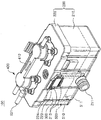
- FIG. 1 is a perspective view of a water level controlling apparatus according to an embodiment of the present invention.
- FIG. 2 is a perspective view showing a state in which a buoy is removed from a main body member of an apparatus main body when the main body member and a cover member are separated in order to cleanse the water level controlling apparatus according to an embodiment of the present invention.
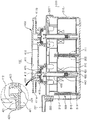
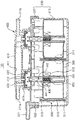
- FIG. 3 is a cross-sectional view of the water level controlling apparatus according to an embodiment of the present invention.
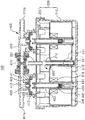
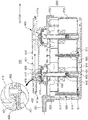
- FIG. 4 is a cross-sectional view of the water level controlling apparatus according to another embodiment of the present invention.
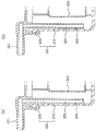
- FIG. 5 is a partial sectional view of a guide unit of the water level controlling apparatus according to another embodiment of the present invention.
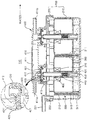
- FIG. 6 is a cross-sectional view of the water level controlling apparatus according to another embodiment of the present invention.
- FIGS. 7 and 8 are cross-sectional views showing an operation of the water level controlling apparatus according to an embodiment of the present invention illustrated in FIG. 3.
- FIG. 9 is an exploded perspective view of the water level controlling apparatus according to another embodiment of the present invention.
- FIG. 10 is a cross-sectional view of the water level controlling apparatus according to another embodiment of the present invention.
- Embodiments of the present invention are based on facilitation of cleansing (i.e., cleaning or washing) of a water level controlling apparatus by configuring the water level controlling apparatus such that a buoy can be easily removed therefrom.
- a water level controlling apparatus 100 may be configured to include an apparatus main body 200, one or more buoys 300, and an opening and closing unit 400.
- the apparatus main body 200 may include a water supply port 221 through which water is introduced and a joint (or a connection member) 211 connected to a water storage tank (not shown) such that the water level of the apparatus main body 200 is the same water level as that of the water storage tank.
- the water supply port 221 may be connected to the opening and closing unit 400 (to be described) connected to a water supply source (not shown).
- the water supply port 221 may be directly connected to the opening and closing unit 400 by a connection pipe (not shown).
- the water storage tank is a purified water tank (not shown) provided in a water purifier (not shown)
- the water supply port 221 may be connected to a plurality of water purification filters (not shown) which are provided in the water purifier and connected to the opening and closing unit 400.
- the water support port 221 may be indirectly connected to the opening and closing unit 400.
- a water level of the water storage tank is lower than a certain water level, namely, a lower end portion of the apparatus main body 200, water introduced into the apparatus main body 200 through the water supply port 221 continues to move to and is stored in the water storage tank through the joint 211, rather than filling the apparatus main body 200. Also, when a water level of the water storage tank is higher than the lower end portion of the apparatus main body 200, the apparatus main body 200 is also filled with water to have the same water level as that of the water storage tank. Thereafter, when water continues to flow into the apparatus main body 200 through the water supply port 221, the water level of the apparatus main body 200 and that of the water storage tank increase equally.
- the joint 211 may have a check valve (not shown) in order to allow water to move to the water storage tank through the joint 211 from the apparatus main body 200 but prevent water from moving from the water storage tank to the apparatus main body 200 through the joint 211.
- the water storage tank may be, for example, a purified water tank provided in a water purifier as mentioned above.
- the present invention is not limited thereto and any water storage tank may be used so long as it can store water.
- the apparatus main body 200 may include a main body member 210 and a cover member 220.
- the main body member 210 may have an open upper portion and have the joint 211. Also, as illustrated, one or more buoys 300 may be provided to ascend or descend within the main body member 210.
- a protrusion extending from a side surface or a lower surface may not be provided within the main body member 210.
- a protrusion may be a member such as a guide rib 212 (to be described), or the like, or a member such as a partition wall 510 or 510' (to be described) partitioning the interior of the main body member 210. Accordingly, cleansing of the interior of the main body member 210 can be facilitated.
- the cover member 220 may be connected to the main body member 210 to cover the open upper portion of the main body member 210.
- connection protrusions 213 and 223 may be disposed on the main body member 210 and the cover member 220, respectively.
- a connection member 224 may be interference-fit between the respective connection protrusions 213 and 223 to connect the cover member 220 to the main body member 210.
- a locking member 225 having a locking recess 225a may be connected to the cover member 220.
- the locking member 225 may be integrated with the cover member 220 and extend from the cover member 220.
- a connection portion connecting the locking member 225 and the cover member 220 may be bent by external force.
- the present invention is not limited to the configuration in which the locking member 225 is connected to the cover member 220; any known configuration such as a configuration in which the locking member 225 is connected to the cover member 220 by a member for connecting, or the like, may be employed.
- a locking protrusion 214 may be provided on the main body 210.
- connection portion connecting the locking member 225 and the cover member 220 may be bent by external force to interference-fit the locking protrusion 214 to the locking recess 225a of the locking member 225, thus connecting the cover member 220 to the main body member 210.
- the configuration in which the cover member 220 is connected to the main body member 210 is not particularly limited to the foregoing example; any configuration may be employed so long as it can easily separate the cover member 220 and the main body member 210 and easily hermetically seal the cover member 220 and the main body member 210 when the cover member 220 and the main body member 210 are connected.
- the water supply port 221 may be disposed on the cover member 220. Accordingly, water from the water supply source flows to an upper portion of the apparatus main body 200 through the water supply port 221 by way of the opening and closing unit 400 (to be described), and water in the apparatus main body 200 may move from a lower portion of the apparatus main body 200 to the water storage tank through the joint 211 so as to be stored therein.
- a water supply guide member 222 may be disposed on the cover member 220 and connected to the water supply port 221.
- the water supply guide member 222 may have a shape that guides water introduced through the water supply port 221 along the wall of the apparatus main body 200. Accordingly, water introduced into the apparatus main body 200 is prevented from flowing to the buoys 300, so it does not affect ascending and descending of the buoys 300.
- a section of the water supply guide member 222 may have a semi-circular shape such that one surface thereof is open toward the wall surface of the apparatus main body 200
- the shape of the water supply guide member 222 is not limited thereto and the water supply guide member 222 may have any known shape so long as it can guide water introduced through the water supply port 221 along the wall of the apparatus main body 200.
- an end portion of the water supply guide member 222 may be positioned at an upper side of the main body member 210 as shown in the embodiment illustrated in FIGS. 3, 6, and 10.
- the buoys 300 may be provided in an ascending and descending manner within the apparatus main body 200. Accordingly, as shown in FIGS. 7 and 8, the buoys 300 may ascend or descend according to a water level of the apparatus main body 200.
- One or more buoys 300 may be disposed in the apparatus main body 200. As shown in the embodiment illustrated in FIGS. 1 through 4, 6, 9, and 10, when two or more, namely, a plurality of, buoys 300 are provided in the apparatus main body 200, even if there is an error in ascending and descending of at least one buoy 300 among the plurality of buoys 300, another buoy 300 may ascend or descend according to a water level of the apparatus main body 200.
- a flow path 411 formed in the opening and closing unit 400 and connected to the water supply port 221 and the water supply source can be opened and closed by a lifting member 440 included in the opening and closing unit 400 (to be described) associated with the buoys 300.
- the water level of the water storage tank can be smoothly controlled without interruption by the water level controlling apparatus according to an embodiment of the present invention.
- buoys 300 may be provided in the apparatus main body 200 or only a single buoy 300 may be provided in the apparatus main body 200.
- a magnet 310 may be provided in the buoy 300.
- an attractive force or a repulsive force based on magnetic force of the magnet 310 may act on the lifting member 440 included in the opening and closing unit 400 according to ascending and descending of the buoy 300.
- the flow path 411 of the opening and closing unit 400 may be opened or closed.
- At least a portion of the main body member 210 may have a shape corresponding to the shape of the buoy 300. Accordingly, even without a member for guiding ascending and descending of the buoy 300 in the main body member 210, ascending and descending of the buoy 300 may be guided by the main body member 210.
- At least a portion of the buoy 300 may be round. Namely, as shown in the embodiment illustrated in FIGS. 9 and 10, a section of the buoy 300 may have a circular shape, an oval shape, or the like, so as to be round. However, besides, a corner portion of the buoy 300 may be round.
- At least a portion of the main body member 210 may be round, to correspond to the shape of the round buoy 300.
- the shape of the buoy 300 and the corresponding shape of the main body member 210 are not limited thereto and the buoy 300 and the main body member 210 may have any shape, so long as the ascending and descending of the buoy 300 are guided by the main body member 210.
- the opening and closing unit 400 may be provided on the cover member 220 included in the apparatus main body 200.
- the flow path 411 may be formed to have one side connected to the water supply source and the other side connected to the water supply port 221. Namely, in the illustrated embodiment, an inlet 411a of the flow path 411 is connected to the water supply source by a connection pipe (not shown), and an outlet 411b of the flow path 411 may be connected to the water supply port 221 by a connection pipe.
- the water supply source is not particularly limited and any water supply source may be employed so long as it can supply water to the flow path 411 of the opening and closing unit 400.
- the flow path 411 of the opening and closing unit 400 may be connected to the water supply port 221 through a plurality of water purification filters (not shown) provided in the water purifier, rather than being directly connected to the water supply port 221.
- the configuration in which the flow path 411 of the opening and closing unit 400 is connected to the water supply port 221 is not particularly limited.
- the opening and closing unit 400 may be associated with one or more buoys 300 provided to ascend and descend in the apparatus main body 200.
- the flow path 411 may be opened and closed, according to a water level of the water storage tank, namely, according to a water level of the apparatus main body 200.
- the water level of the water storage tank may be controlled thereby.
- the flow path 411 of the opening and closing unit 400 is open no matter whether the buoy 300 does not ascend or ascends in the apparatus main body 200. Accordingly, water from the water supply source flows in the flow path 411 so as to be introduced into the apparatus main body 200 through the water supply port 221, and then, moves to the water storage tank through the joint 211 so as to be stored.
- the buoy 300 When the water level of the water storage tank is full, as shown in FIG. 8, the buoy 300 ascends to the maximum height within the apparatus main body 200, closing the flow path 411 of the opening and closing unit 400. Accordingly, water supply from the water supply source to the water storage tank is stopped.
- the buoy 300 may be removed.
- the main body member 210 can be easily cleansed, enhancing the hygiene of the water level controlling apparatus 100, and accordingly, the hygiene of the water storage tank connected to the water level controlling apparatus 100 can also be enhanced.
- the opening and closing unit 400 may include an opening and closing unit main body 410, a connection member 420, a buoy guide member 430, and a lifting member 440.
- the foregoing flow path 411 may be formed on the opening and closing unit main body 410. Also, a connection hole 412 connected to the flow path 411 may be formed on the opening and closing unit main body 410. A chamber 413 may be formed to be connected to the connection hole 412 and the cover member 220.
- connection hole 412 and one chamber 413 may be formed on the opening and closing unit main body 410.
- a plurality of connection holes 412 and a plurality of chambers 413 may be formed to correspond to the number of the buoys 300.
- a plurality of opening and closing unit main bodies 410 each having a connection hole 412 and a chamber 413 formed thereon, may be provided in the apparatus main body 200 such that they are associated with the plurality of buoys 300, respectively.
- the flow path 411 of the respective opening and closing unit main bodies 410 may be connected by a connection pipe 414.
- connection member 420 may be provided in the chamber 413 such that one side thereof is inserted into the connection hole 412. Also, the connection member 420 may include a communication hole 421 connected to the flow path 411 and an opening and closing hole 422 connected to the connection hole 412.
- water introduced into the flow path 411 through the inlet 411a from the water supply source may be introduced into the chamber 413 through the communication hole 421, and then, introduced into the flow path 411 again through the opening and closing hole 422, so as to be discharged through the outlet 411b.
- a sealing member 423 may be disposed on the connection member 420 to hermetically seal a gap between one side of the connection member 420 inserted into the connection hole 412 and the connection hole 412.
- a communication hole 421' may be formed on the sealing member 423 and connected to the communication hole 421 of the connection member 420.
- one side of the buoy guide member 430 may be provided at the cover member 220 so as to be connected to the chamber 413 of the opening and closing unit main body 410. Also, the other side of the buoy guide member 430 may penetrate the buoy 300. In the case in which the other side of the buoy guide member 430 penetrates the buoy 300, a stop member 431 may be provided at the other side of the buoy guide member 430.
- the buoy 300 can be readily removed from the main body member 210 along with the buoy guide member 430.
- the main body member 210 can be easily cleansed, enhancing the hygiene of the water level controlling apparatus 100, and accordingly, the hygiene of the water storage tank connected to the water level controlling apparatus 100 can also be enhanced.
- the buoy 300 when the stop member 431 is separated from the buoy guide member 430, the buoy 300 can be easily separated from the buoy guide member 430. Accordingly, the buoy 300 can be easily cleansed, enhancing the hygiene of the water level controlling apparatus 100. In addition, the hygiene of the water storage tank connected to the water level controlling apparatus 100 can also be enhanced.
- ascending and descending of the buoy 300 may be guided by the buoy guide member 430.
- the lifting member 440 may be provided to be lifted or lowered within the buoy guide member 430. Also, the lifting member 440 may be lifted or lowered by magnetic force of the magnet 310 provided in the buoy 300 according to ascending and descending of the buoy 300. Accordingly, as shown in FIGS. 7 and 8, the opening and closing hole 422 of the connection member 420 may be opened and closed.
- the lifting member 440 which opens and closes the opening and closing hole 422 of the connection member 420, is made of metal or formed of a magnet, or includes a plurality of magnets, as explained hereafter, is provided within the buoy guide member 430, water introduced into the apparatus main body 200 is not directly in contact with the lifting member 440.
- hygiene of the water level controlling apparatus 100 can be enhanced and that of the water storage tank connected to the water level controlling apparatus 100 can also be enhanced.
- the lifting member 440 may be made of a metal such as iron, or the like.
- the water level of the apparatus main body 200 is also lowered, and thus, the buoy 300 is lowered or is in a lowered state.
- the lifting member 440 may be lowered along with the buoy 300 or be in a lowered state along with the buoy 300, according to an attractive force acting by the magnetic force of the magnet 310 provided in the buoy 300.
- the opening and closing hole 422 of the connection member 420 is opened to allow water from the water supply source to flow through the flow path 411 so as to be introduced into the apparatus main body 200 through the water supply port 221, and the water introduced into the apparatus main body 200 moves to the water storage tank through the joint 211.
- the lifting member 440 is lifted by attractive force exerted by the magnetic force of the magnet 310 installed in the buoy 300.
- the buoy 300 When the water level of the water storage tank is full, as shown in FIG. 8, the buoy 300 ascends to the maximum height within the apparatus main body 200, and accordingly, the lifting member 440 closes the opening and closing hole 422 of the connection member 420.
- the flow path 411 is closed and water supply from the water supply source to the water storage tank is stopped.
- the lifting member 440 may be configured as a magnet having a plurality of steps 441.
- a magnetic line of force is formed to allow each of the steps 441 to serve as a magnet.
- this may have an effect that a plurality of magnets are provided to be spaced apart from one another in the lifting member 440.
- a plurality of magnets may be provided to be spaced apart from one another in the lifting member 440.
- a repulsive force may act on the lifting member 440 according to interaction between a magnetic force by the magnet 310 of the buoy 300 and a magnetic force by some of steps 441 of the lifing member 440 close to the magnet 310 of the buoy 300 or by some of magnets provided in the lifting member 440 close to the magnet 310 of the buoy 300.
- a magnetic force of some of the plurality of steps 441 or some of the plurality of magnets may decline, a magnetic force by the other steps 441 or the other magnets and a magnetic force by the magnet of the buoy 310 may interact to apply a repulsive force to the lifting member 410.
- the lifting member 440 can be easily, reliably lifted and lowered, according to ascending and descending of the buoy 300.
- the buoy 300 when the buoy 300 is lowered or is in a lowered state as the water level of the water storage tank and that of the apparatus main body 200 is lowered, the foregoing repulsive force does not reach (or is not applied to) the lifting member 440.
- the lifting member 440 is lowered or in a lowered state by its own weight.
- the opening and closing hole 422 of the connection member 420 is opened to allow water from the water supply source to flow along the flow path 411 so as to be introduced into the apparatus main body 200 through the water supply port 221, and the water introduced into the apparatus main body 200 moves to the water storage tank through the joint 211 so as to be stored therein.
- the lifting member 440 is also lifted by the foregoing repulsive force.
- the buoy 300 When the water level of the water storage tank is a full water level, the buoy 300 ascends to a maximum height within the apparatus main body 200, and accordingly, the lifting member 440 closes the opening and closing hole 422 of the connection member 420.
- the flow path 411 is closed to stop water supply from the water supply source to the water storage tank.
- the opening and closing unit 400 may further include an elastic member 450.
- the elastic member 450 may be provided within the buoy guide member 430 in order to elastically support the lifting member 440.
- the buoy 300 has been lowered, so the lifting member 440 is lowered by self-weight without the foregoing repulsive force, the elastic member 450 may buffer the lifting member 440 during lowering thereof. Thus, noise generation due to lowering of the lifting member 440 can be prevented.
- the water level controlling apparatus may further include a guide unit 500.
- the guide unit 500 may be provided within the apparatus main body 200 adjacent to the water supply port 221.
- the guide unit 500 may guide water to be introduced into the apparatus main body 200 without affecting ascending and descending of the buoy 300.
- the buoy 300 may reliably ascend and descend according to the water level of the water storage tank, and accordingly, the water level of the water storage tank can be reliably controlled by the water level controlling apparatus 100.
- the guide unit 500 may include a partition wall 510 having one or more through holes 511 formed in a lower portion thereof allowing water to pass therethrough.
- water introduced into the apparatus main body 200 through the water supply port 221 flows to the lower portion of the apparatus main body 200 along the partition wall 510 and passes through the through holes 511 of the partition wall 510 so as to fill the apparatus main body 200 from the lower portion thereof.
- the partition wall 510 may be positioned to be spaced apart from the lower portion of the apparatus main body 200 in order to allow water to pass therethrough.
- the water supply port 221 may be provided at an upper portion of the apparatus main body 200 between the buoys 300.
- the guide unit 500 may include a partition wall 510' provided within the apparatus main body 200 between buoys 300. Also, a section of the partition wall 510' may have a 'U'-like shape. One or more through holes 511' allowing water to pass therethrough may be formed on the lower portion of the partition wall 510.
- water introduced into the apparatus main body 200 through the water supply port 221 flows to the lower portion of the apparatus main body 200 along the partition wall 510' and passes through the through holes 511' of the partition wall 510' so as to fill up from the lower portion of the apparatus main body 200.
- the guide unit 500 may be provided within the apparatus main body 200 between the buoys 300 and include a plurality of partition walls 510 which have the through holes 511 formed at a lower portion thereof and allow water to pass therethrough or which are positioned to be spaced apart from the lower portion of the apparatus main body 200.
- the partition walls 510 and 510' are inserted into a guide rib 212 formed in the main body member 210 so as to be provided within the apparatus main body 200.
- the configuration in which the partition walls 510 and 510' are provided within the apparatus main body 200 is not limited to the illustrated embodiment, and any configuration may be employed so long as the partition walls 510 and 510' are provided within the apparatus main body 200, namely, for example, the partition walls 510 and 510' are connected to the cover member 220 so as to be provided within the apparatus main body 200, or the like.
- the partition walls 510 and 510' are connected to the cover member 220 so as to be provided within the apparatus main body 200, as mentioned above, when the cover member 220 is separated from the main body member 210 in order to cleanse the main body member 210, even the partition walls 510 and 510', as well as the buoy 300, can be easily removed from the main body member 210.
- the main body member 210 can be easily cleansed, the hygiene of the water level controlling apparatus 100 can be enhanced, and accordingly, the hygiene of the water storage tank connected to the water level controlling apparatus 100 can also be enhanced.
- the guide unit 500 may include a guide member 520.
- One side of the guide member 520 may be connected to the water supply port 221.
- the other side of the guide member 520 may be positioned below a central portion in the apparatus main body 200.
- a section of the guide member 520 may have a semi-circular shape as shown in the embodiment illustrated in FIG. 5(a), or may have a tubular shape as shown in the embodiment illustrated in FIG. 5(b).
- the shape of the guide member 520 is not particularly limited and the guide member 520 may have any shape so long as it does not affect ascending and descending of the buoy 300 and allows water to be introduced into the apparatus main body 200.
- the guide member 520 may be used in the place of the partition wall 510' having the through holes 511' and having the 'U'-like shape or the plurality of partition walls 510 having the through holes 511 formed thereon or positioned to be spaced apart from the lower portion of the apparatus main body 200.
- partition walls 510 and 510' or the guide member 520 as shown in the embodiment illustrated in FIGS. 3, 4, and 6, only a single partition wall or only a single guide member may be included in the guide unit 500, or a plurality of partition walls or a plurality of guide members may be combined to be included in the guide unit 500.
- a buoy can be easily removed from the water level controlling apparatus, the water level controlling apparatus can be easily cleansed, and the hygiene of the water storage tank to which the water level controlling apparatus is connected can be enhanced.
- the configuration of the foregoing embodiment is not limitedly applied but the entirety or a portion of the respective embodiments may be selectively combined to be configured into various modifications.
Landscapes
- Life Sciences & Earth Sciences (AREA)
- Hydrology & Water Resources (AREA)
- Engineering & Computer Science (AREA)
- Environmental & Geological Engineering (AREA)
- Water Supply & Treatment (AREA)
- Chemical & Material Sciences (AREA)
- Organic Chemistry (AREA)
- Level Indicators Using A Float (AREA)
- Control Of Non-Electrical Variables (AREA)
Abstract
An apparatus for controlling water level of water storage tank includes: an apparatus main body including a main body member connected to a water storage tank and having an open upper portion, and a cover member connected to the main body member; one or more buoys provided in an ascending and descending manner within the apparatus main body; and an opening and closing unit provided on the cover member, including a flow path having one side connected to a water supply source and the other side connected to the water supply port, and associated with the one or more buoys such that the flow path is opened or closed according to a water level of the water storage tank and the one or more buoys can be removed when the main body member and the cover member are separated.
Description
The present invention relates to an apparatus for controlling a water level (referred to as a 'a water level controlling apparatus', hereinafter) connected to a water storage tank and controlling a water level thereof by opening and closing a flow path connected to a water supply source according to ascending and descending of a buoy, and more particularly, to a water level controlling apparatus that can be easily cleansed (i.e., cleaned or washed) by allowing a buoy to be readily removed therefrom.
A water level controlling apparatus, an apparatus for controlling a water level of a water storage tank, may be classified as an electronic water level controlling apparatus for controlling a water level electronically or a mechanical water level controlling apparatus for controlling a water level mechanically.
The electronic water level controlling apparatus is configured to be connected to one or more water level sensors provided in a water storage tank and to open or close a flow path connected to a water supply source according to a water level of the water storage tank to supply water to the water storage tank or to stop the supply of water to the water storage tank, thus controlling the water level of the water storage tank.
The mechanical water level controlling apparatus is configured to open or close a flow path connected to a water supply source according to a buoy ascending and descending, according to a water level of a water storage tank to supply water to the water storage tank or to stop the supply of water to the water storage tank, thus controlling the water level of the water storage tank.
These water level controlling apparatuses may be provided within the water storage tank or may be provided on the outside of the water storage tank and connected to the inside thereof.
However, the related art mechanical water level controlling apparatus, provided outside a water storage tank, connected to the water storage tank, and controlling a water level of the water storage tank by a buoy ascending and descending according to the water level of the water storage tank, has a problem in that the buoy cannot be easily removed from the water level controlling apparatus.
Thus, the water level controlling apparatus cannot be easily cleansed, and for this reason, the water level controlling apparatus may be contaminated to thereby degrade the hygiene of the water storage tank connected to the water level controlling apparatus.
The present invention is based upon recognition of any one of the requests or issues arising from the above-referenced related art water level controlling apparatus.
An aspect of the present invention provides a water level controlling apparatus allowing a buoy disposed therein to be easily removed.
Another aspect of the present invention provides a water level controlling apparatus that can be easily cleansed.
Another aspect of the present invention provides a water level controlling apparatus capable of enhancing the hygiene of a water storage tank connected thereto.
A water level controlling apparatus in relation to an embodiment of the present invention may have the following characteristics.
The present invention is based on facilitation of the cleansing of a water level controlling apparatus by configuring the water level controlling apparatus such that a buoy can be easily removed therefrom.
According to an aspect of the present invention, there is provided a water level controlling apparatus including: an apparatus main body including a main body member having a joint (or a connection portion) connected to a water storage tank and having an open upper portion, and a cover member having a water supply port and connected to the main body member; one or more buoys provided in an ascending and descending manner within the apparatus main body such that they can ascend or descend according to a water level of the apparatus main body; an opening and closing unit provided on the cover member, including a flow path having one side connected to a water supply source and the other side connected to the water supply port, and associated with the one or more buoys such that the flow path is opened or closed according to a water level of the water storage tank and the one or more buoys can be removed when the main body member and the cover member are separated.
The opening and closing unit may include: an opening and closing unit main body including the flow path, a connection hole connected to the flow path, and a chamber connected to the connection hole and the cover member; a connection member provided in the chamber such that one side thereof may be inserted into the connection hole and having a communication hole communicating with the flow path and an opening and closing hole communicating with the connection hole; a buoy guide member having one side provided in the cover member so as to be connected to the chamber and the other side penetrating the buoy having a magnet therein; and a lifting member provided within the buoy guide member such that it can be lifted and lowered, and lifted and lowered by magnetic force of the magnet according to ascending and descending of the buoy to open and close the opening and closing hole.
The opening and closing unit may further include: an elastic member provided within the buoy guide member in order to elastically support the lifting member.
The lifting member may be configured as a magnet having a plurality of steps or a plurality of magnets may be provided to be spaced apart from one another.
A stop member may be provided at the other side of the buoy guide member.
The water level controlling apparatus may further include: a guide unit provided within the apparatus main body adjacent to the water supply port and guiding water such that water is introduced without affecting ascending and descending of the buoy.
The guide unit may include one or more partition walls having one or more through holes formed in a lower portion thereof to allow water to pass therethrough, or disposed to be spaced apart from a lower portion of the apparatus main body by a certain distance.
A plurality of buoys may be provided within the apparatus main body, the water supply port may be provided at an upper portion of the apparatus main body between the buoys, and the guide unit may have a section having a 'U'-like shape and include a partition wall having one or more through holes formed in a lower portion thereof to allow water to pass therethrough.
The guide unit may include a guide member having one side connected to the water supply port and the other side positioned below a central portion in the apparatus main body.
At least a portion of the main body member may have a shape corresponding to the shape of the buoy.
At least a portion of the buoy may be round, and at least a portion of the main body member may be round, to correspond to the shape of the buoy.
A protrusion extending from a side surface or a lower surface is not provided within the main body member so as to facilitate washing.
A water supply guide member may be provided to be connected to the water supply port in the cover member.
The water supply guide member may have a shape that guides water introduced through the water supply port along the wall of the apparatus main body.
A locking member having a locking recess may be connected to the cover member, and a locking protrusion may be provided on the main body member and inserted into the locking recess.
As set forth above, according to an embodiment of the invention, buoys can be readily removed from the water level controlling apparatus.
Also, according to an embodiment of the invention, the water level controlling apparatus can be easily cleansed.
Also, according to an embodiment of the invention, the hygiene of the water storage tank to which the water level controlling apparatus is connected can be enhanced.
The above and other aspects, features and other advantages of the present invention will be more clearly understood from the following detailed description taken in conjunction with the accompanying drawings, in which:
FIG. 1 is a perspective view of a water level controlling apparatus according to an embodiment of the present invention.
FIG. 2 is a perspective view showing a state in which a buoy is removed from a main body member of an apparatus main body when the main body member and a cover member are separated in order to cleanse the water level controlling apparatus according to an embodiment of the present invention.
FIG. 3 is a cross-sectional view of the water level controlling apparatus according to an embodiment of the present invention.
FIG. 4 is a cross-sectional view of the water level controlling apparatus according to another embodiment of the present invention.
FIG. 5 is a partial sectional view of a guide unit of the water level controlling apparatus according to another embodiment of the present invention.
FIG. 6 is a cross-sectional view of the water level controlling apparatus according to another embodiment of the present invention.
FIGS. 7 and 8 are cross-sectional views showing an operation of the water level controlling apparatus according to an embodiment of the present invention illustrated in FIG. 3.
FIG. 9 is an exploded perspective view of the water level controlling apparatus according to another embodiment of the present invention.
FIG. 10 is a cross-sectional view of the water level controlling apparatus according to another embodiment of the present invention.
In order to help understand the characteristics of the present invention, a water level controlling apparatus in relation to an embodiment of the present invention will be described in detail hereafter.
Embodiments of the present invention will now be described in detail with reference to the accompanying drawings. The invention may, however, be embodied in many different forms and should not be construed as being limited to the embodiments set forth herein. Rather, these embodiments are provided so that this disclosure will be thorough and complete, and will fully convey the scope of the invention to those skilled in the art. In the drawings, the shapes and dimensions of elements may be exaggerated for clarity, and the same reference numerals will be used throughout to designate the same or like components.
Embodiments of the present invention are based on facilitation of cleansing (i.e., cleaning or washing) of a water level controlling apparatus by configuring the water level controlling apparatus such that a buoy can be easily removed therefrom.
A water level controlling apparatus 100 according to an embodiment of the present invention illustrated in FIGS. 1 through 4, 6, 9, and 10 may be configured to include an apparatus main body 200, one or more buoys 300, and an opening and closing unit 400.
As shown in the embodiment illustrated in FIGS. 1 through 4, 6, 9, and 10, the apparatus main body 200 may include a water supply port 221 through which water is introduced and a joint (or a connection member) 211 connected to a water storage tank (not shown) such that the water level of the apparatus main body 200 is the same water level as that of the water storage tank.
The water supply port 221 may be connected to the opening and closing unit 400 (to be described) connected to a water supply source (not shown). The water supply port 221 may be directly connected to the opening and closing unit 400 by a connection pipe (not shown). However, for example, if the water storage tank is a purified water tank (not shown) provided in a water purifier (not shown), the water supply port 221 may be connected to a plurality of water purification filters (not shown) which are provided in the water purifier and connected to the opening and closing unit 400. Namely, the water support port 221 may be indirectly connected to the opening and closing unit 400.
With such a configuration, as shown in FIG. 7, water from the water supply source flows into the apparatus main body 200 through the water supply port 221. Then, water introduced into the apparatus main body 200 moves to the water storage tank through the joint 211.
If a water level of the water storage tank is lower than a certain water level, namely, a lower end portion of the apparatus main body 200, water introduced into the apparatus main body 200 through the water supply port 221 continues to move to and is stored in the water storage tank through the joint 211, rather than filling the apparatus main body 200. Also, when a water level of the water storage tank is higher than the lower end portion of the apparatus main body 200, the apparatus main body 200 is also filled with water to have the same water level as that of the water storage tank. Thereafter, when water continues to flow into the apparatus main body 200 through the water supply port 221, the water level of the apparatus main body 200 and that of the water storage tank increase equally.
Meanwhile, although not shown, the joint 211 may have a check valve (not shown) in order to allow water to move to the water storage tank through the joint 211 from the apparatus main body 200 but prevent water from moving from the water storage tank to the apparatus main body 200 through the joint 211.
The water storage tank may be, for example, a purified water tank provided in a water purifier as mentioned above. However, the present invention is not limited thereto and any water storage tank may be used so long as it can store water.
As shown in the embodiment illustrated in FIGS. 1 through 4, 6, 9, and 10, the apparatus main body 200 may include a main body member 210 and a cover member 220.
As shown in the embodiment illustrated in FIGS. 1 through 4, 6, 9, and 10, the main body member 210 may have an open upper portion and have the joint 211. Also, as illustrated, one or more buoys 300 may be provided to ascend or descend within the main body member 210.
Meanwhile, as shown in the embodiment illustrated in FIGS 9 and 10, a protrusion extending from a side surface or a lower surface may not be provided within the main body member 210. Such a protrusion may be a member such as a guide rib 212 (to be described), or the like, or a member such as a partition wall 510 or 510' (to be described) partitioning the interior of the main body member 210. Accordingly, cleansing of the interior of the main body member 210 can be facilitated.
Also, as shown in the embodiment illustrated in FIGS. 1 through 4, 6, 9, and 10, the cover member 220 may be connected to the main body member 210 to cover the open upper portion of the main body member 210.
In order to connect the cover member 220 to the main body member 210, as shown in the embodiment illustrated in FIGS. 1 and 2, connection protrusions 213 and 223 may be disposed on the main body member 210 and the cover member 220, respectively. A connection member 224 may be interference-fit between the respective connection protrusions 213 and 223 to connect the cover member 220 to the main body member 210.
Also, as shown in the embodiment illustrated in FIGS. 9 and 10, a locking member 225 having a locking recess 225a may be connected to the cover member 220. To this end, the locking member 225 may be integrated with the cover member 220 and extend from the cover member 220. According to this configuration, a connection portion connecting the locking member 225 and the cover member 220 may be bent by external force. However, the present invention is not limited to the configuration in which the locking member 225 is connected to the cover member 220; any known configuration such as a configuration in which the locking member 225 is connected to the cover member 220 by a member for connecting, or the like, may be employed.
As shown in the embodiment illustrated in FIGS. 9 and 10, a locking protrusion 214 may be provided on the main body 210.
According to such a configuration, the connection portion connecting the locking member 225 and the cover member 220 may be bent by external force to interference-fit the locking protrusion 214 to the locking recess 225a of the locking member 225, thus connecting the cover member 220 to the main body member 210.
However, the configuration in which the cover member 220 is connected to the main body member 210 is not particularly limited to the foregoing example; any configuration may be employed so long as it can easily separate the cover member 220 and the main body member 210 and easily hermetically seal the cover member 220 and the main body member 210 when the cover member 220 and the main body member 210 are connected.
Also, as shown in the embodiment illustrated in FIGS. 1 through 4, 6, 9, and 10, the water supply port 221 may be disposed on the cover member 220. Accordingly, water from the water supply source flows to an upper portion of the apparatus main body 200 through the water supply port 221 by way of the opening and closing unit 400 (to be described), and water in the apparatus main body 200 may move from a lower portion of the apparatus main body 200 to the water storage tank through the joint 211 so as to be stored therein.
Also, as shown in the embodiment illustrated in FIGS. 3, 6, 9, and 10, a water supply guide member 222 may be disposed on the cover member 220 and connected to the water supply port 221. The water supply guide member 222 may have a shape that guides water introduced through the water supply port 221 along the wall of the apparatus main body 200. Accordingly, water introduced into the apparatus main body 200 is prevented from flowing to the buoys 300, so it does not affect ascending and descending of the buoys 300.
To this end, for example, as shown in the embodiment illustrated in FIGS. 3, 6, and 10, a section of the water supply guide member 222 may have a semi-circular shape such that one surface thereof is open toward the wall surface of the apparatus main body 200
However, the shape of the water supply guide member 222 is not limited thereto and the water supply guide member 222 may have any known shape so long as it can guide water introduced through the water supply port 221 along the wall of the apparatus main body 200.
Also, an end portion of the water supply guide member 222 may be positioned at an upper side of the main body member 210 as shown in the embodiment illustrated in FIGS. 3, 6, and 10.
As shown in the embodiment illustrated in FIGS. 1 through 4, 6, 9, and 10, the buoys 300 may be provided in an ascending and descending manner within the apparatus main body 200. Accordingly, as shown in FIGS. 7 and 8, the buoys 300 may ascend or descend according to a water level of the apparatus main body 200.
One or more buoys 300 may be disposed in the apparatus main body 200. As shown in the embodiment illustrated in FIGS. 1 through 4, 6, 9, and 10, when two or more, namely, a plurality of, buoys 300 are provided in the apparatus main body 200, even if there is an error in ascending and descending of at least one buoy 300 among the plurality of buoys 300, another buoy 300 may ascend or descend according to a water level of the apparatus main body 200.
Thus, even in the case there is an error in the ascending and descending of at least one buoy 300 among the plurality of buoys 300, a flow path 411 formed in the opening and closing unit 400 and connected to the water supply port 221 and the water supply source can be opened and closed by a lifting member 440 included in the opening and closing unit 400 (to be described) associated with the buoys 300. Thus, the water level of the water storage tank can be smoothly controlled without interruption by the water level controlling apparatus according to an embodiment of the present invention.
However, as illustrated in FIGS. 1 through 4, 6, 9, and 10 and as mentioned above, two or more, i.e., a plurality of, buoys 300 may be provided in the apparatus main body 200 or only a single buoy 300 may be provided in the apparatus main body 200.
Meanwhile, as shown in the embodiment illustrated in FIGS. 3, 4, 6, and 10, a magnet 310 may be provided in the buoy 300. As explained hereafter, an attractive force or a repulsive force based on magnetic force of the magnet 310 may act on the lifting member 440 included in the opening and closing unit 400 according to ascending and descending of the buoy 300. As the lifting member 440 is lifted or lowered, the flow path 411 of the opening and closing unit 400 may be opened or closed.
As shown in the embodiment illustrated in FIGS. 2 through 4, 6, 9, and 10, at least a portion of the main body member 210 may have a shape corresponding to the shape of the buoy 300. Accordingly, even without a member for guiding ascending and descending of the buoy 300 in the main body member 210, ascending and descending of the buoy 300 may be guided by the main body member 210.
As shown in the embodiment illustrated in FIGS. 9 and 10, at least a portion of the buoy 300 may be round. Namely, as shown in the embodiment illustrated in FIGS. 9 and 10, a section of the buoy 300 may have a circular shape, an oval shape, or the like, so as to be round. However, besides, a corner portion of the buoy 300 may be round.
As shown in the embodiment illustrated in FIGS. 9 and 10, at least a portion of the main body member 210 may be round, to correspond to the shape of the round buoy 300.
However, the shape of the buoy 300 and the corresponding shape of the main body member 210 are not limited thereto and the buoy 300 and the main body member 210 may have any shape, so long as the ascending and descending of the buoy 300 are guided by the main body member 210.
As shown in the embodiment illustrated in FIGS. 1 through 4, 6, 9, and 10, the opening and closing unit 400 may be provided on the cover member 220 included in the apparatus main body 200. The flow path 411 may be formed to have one side connected to the water supply source and the other side connected to the water supply port 221. Namely, in the illustrated embodiment, an inlet 411a of the flow path 411 is connected to the water supply source by a connection pipe (not shown), and an outlet 411b of the flow path 411 may be connected to the water supply port 221 by a connection pipe.
The water supply source is not particularly limited and any water supply source may be employed so long as it can supply water to the flow path 411 of the opening and closing unit 400. Also, for example, when the water storage tank is a purified water tank provided in a water purifier as mentioned above, the flow path 411 of the opening and closing unit 400 may be connected to the water supply port 221 through a plurality of water purification filters (not shown) provided in the water purifier, rather than being directly connected to the water supply port 221. However, the configuration in which the flow path 411 of the opening and closing unit 400 is connected to the water supply port 221 is not particularly limited.
Also, as shown in the embodiment illustrated in FIGS. 1 through 4, 6, 9, and 10, the opening and closing unit 400 may be associated with one or more buoys 300 provided to ascend and descend in the apparatus main body 200.
Accordingly, as illustrated in FIGS. 7 and 8, the flow path 411 may be opened and closed, according to a water level of the water storage tank, namely, according to a water level of the apparatus main body 200. The water level of the water storage tank may be controlled thereby.
Namely, when the water level of the water storage tank is not full, as shown in FIG. 7, the flow path 411 of the opening and closing unit 400 is open no matter whether the buoy 300 does not ascend or ascends in the apparatus main body 200. Accordingly, water from the water supply source flows in the flow path 411 so as to be introduced into the apparatus main body 200 through the water supply port 221, and then, moves to the water storage tank through the joint 211 so as to be stored.
When the water level of the water storage tank is full, as shown in FIG. 8, the buoy 300 ascends to the maximum height within the apparatus main body 200, closing the flow path 411 of the opening and closing unit 400. Accordingly, water supply from the water supply source to the water storage tank is stopped.
Also, as illustrated in FIG. 2, when the main body member 210 and the cover member 220 are separated, the buoy 300 may be removed. Thus, the main body member 210 can be easily cleansed, enhancing the hygiene of the water level controlling apparatus 100, and accordingly, the hygiene of the water storage tank connected to the water level controlling apparatus 100 can also be enhanced.
To this end, as shown in the embodiment illustrated in FIGS. 3, 4, 6, 9, and 10, the opening and closing unit 400 may include an opening and closing unit main body 410, a connection member 420, a buoy guide member 430, and a lifting member 440.
As shown in the embodiment illustrated in FIGS. 3, 4, 6, 9, and 10, the foregoing flow path 411 may be formed on the opening and closing unit main body 410. Also, a connection hole 412 connected to the flow path 411 may be formed on the opening and closing unit main body 410. A chamber 413 may be formed to be connected to the connection hole 412 and the cover member 220.
Meanwhile, when only a single buoy 300 is provided in the apparatus main body 200, one connection hole 412 and one chamber 413 may be formed on the opening and closing unit main body 410. However, as shown in the embodiment illustrated in FIGS. 3, 4, 6, 9, and 10, when two or more, namely, a plurality of, buoys 300 are provided in the apparatus main body 200, a plurality of connection holes 412 and a plurality of chambers 413 may be formed to correspond to the number of the buoys 300.
Also, as shown in the embodiment illustrated in FIG. 4, when a plurality of buoys 300 are provided in the apparatus main body 200, a plurality of opening and closing unit main bodies 410, each having a connection hole 412 and a chamber 413 formed thereon, may be provided in the apparatus main body 200 such that they are associated with the plurality of buoys 300, respectively. As shown in the embodiment illustrated in FIG. 4, the flow path 411 of the respective opening and closing unit main bodies 410 may be connected by a connection pipe 414.
As shown in the embodiment illustrated in FIGS. 3, 4, 6, 9, and 10, the connection member 420 may be provided in the chamber 413 such that one side thereof is inserted into the connection hole 412. Also, the connection member 420 may include a communication hole 421 connected to the flow path 411 and an opening and closing hole 422 connected to the connection hole 412.
Accordingly, as shown in FIG. 7, when the opening and closing hole 422 is not closed by the lifting member 440 (to be described) included in the opening and closing unit 400, water introduced into the flow path 411 through the inlet 411a from the water supply source may be introduced into the chamber 413 through the communication hole 421, and then, introduced into the flow path 411 again through the opening and closing hole 422, so as to be discharged through the outlet 411b.
Meanwhile, as shown in the embodiment illustrated in FIGS. 3, 4, 6, 9, and 10, a sealing member 423 may be disposed on the connection member 420 to hermetically seal a gap between one side of the connection member 420 inserted into the connection hole 412 and the connection hole 412. As shown in the embodiment illustrated in FIGS. 3, 4, 6, 9, and 10, a communication hole 421' may be formed on the sealing member 423 and connected to the communication hole 421 of the connection member 420.
As shown in the embodiment illustrated in FIGS. 3, 4, 6, 9, and 10, one side of the buoy guide member 430 may be provided at the cover member 220 so as to be connected to the chamber 413 of the opening and closing unit main body 410. Also, the other side of the buoy guide member 430 may penetrate the buoy 300. In the case in which the other side of the buoy guide member 430 penetrates the buoy 300, a stop member 431 may be provided at the other side of the buoy guide member 430.
Thus, even in the case that the buoy 300 descends, the buoy 300 cannot be released from the buoy guide member 430, and as illustrated in FIG. 2, when the cover member 220 is separated from the main body member 210, the buoy 300 can be readily removed from the main body member 210 along with the buoy guide member 430. Thus, the main body member 210 can be easily cleansed, enhancing the hygiene of the water level controlling apparatus 100, and accordingly, the hygiene of the water storage tank connected to the water level controlling apparatus 100 can also be enhanced.
Also, when the stop member 431 is separated from the buoy guide member 430, the buoy 300 can be easily separated from the buoy guide member 430. Accordingly, the buoy 300 can be easily cleansed, enhancing the hygiene of the water level controlling apparatus 100. In addition, the hygiene of the water storage tank connected to the water level controlling apparatus 100 can also be enhanced.
As shown in FIGS. 7 and 8, ascending and descending of the buoy 300 may be guided by the buoy guide member 430.
As shown in the embodiment illustrated in FIGS. 3, 4, 6, 9, and 10, the lifting member 440 may be provided to be lifted or lowered within the buoy guide member 430. Also, the lifting member 440 may be lifted or lowered by magnetic force of the magnet 310 provided in the buoy 300 according to ascending and descending of the buoy 300. Accordingly, as shown in FIGS. 7 and 8, the opening and closing hole 422 of the connection member 420 may be opened and closed.
Since the lifting member 440, which opens and closes the opening and closing hole 422 of the connection member 420, is made of metal or formed of a magnet, or includes a plurality of magnets, as explained hereafter, is provided within the buoy guide member 430, water introduced into the apparatus main body 200 is not directly in contact with the lifting member 440. Thus, hygiene of the water level controlling apparatus 100 can be enhanced and that of the water storage tank connected to the water level controlling apparatus 100 can also be enhanced.
As shown in the embodiment illustrated in FIGS. 3, 4, 9, and 10, the lifting member 440 may be made of a metal such as iron, or the like.
When the water level of the water storage tank is lowered, as shown in FIG. 7, the water level of the apparatus main body 200 is also lowered, and thus, the buoy 300 is lowered or is in a lowered state. The lifting member 440 may be lowered along with the buoy 300 or be in a lowered state along with the buoy 300, according to an attractive force acting by the magnetic force of the magnet 310 provided in the buoy 300.
Accordingly, the opening and closing hole 422 of the connection member 420 is opened to allow water from the water supply source to flow through the flow path 411 so as to be introduced into the apparatus main body 200 through the water supply port 221, and the water introduced into the apparatus main body 200 moves to the water storage tank through the joint 211.
Also, when the water level of the water storage tank rises, according to water supply to the water storage tank, the water level of the apparatus main body 200 also rises to make the buoy 300 ascend. Also, the lifting member 440 is lifted by attractive force exerted by the magnetic force of the magnet 310 installed in the buoy 300.
When the water level of the water storage tank is full, as shown in FIG. 8, the buoy 300 ascends to the maximum height within the apparatus main body 200, and accordingly, the lifting member 440 closes the opening and closing hole 422 of the connection member 420.
Accordingly, the flow path 411 is closed and water supply from the water supply source to the water storage tank is stopped.
Meanwhile, as shown in the embodiment illustrated in FIG. 6, the lifting member 440 may be configured as a magnet having a plurality of steps 441. When the lifting member 440 is configured as a magnet having a plurality of steps 441, a magnetic line of force is formed to allow each of the steps 441 to serve as a magnet. Thus, this may have an effect that a plurality of magnets are provided to be spaced apart from one another in the lifting member 440.
Although not shown, a plurality of magnets may be provided to be spaced apart from one another in the lifting member 440.
When the lifting member 440 has such a configuration, a repulsive force may act on the lifting member 440 according to interaction between a magnetic force by the magnet 310 of the buoy 300 and a magnetic force by some of steps 441 of the lifing member 440 close to the magnet 310 of the buoy 300 or by some of magnets provided in the lifting member 440 close to the magnet 310 of the buoy 300.
Also, although a magnetic force of some of the plurality of steps 441 or some of the plurality of magnets may decline, a magnetic force by the other steps 441 or the other magnets and a magnetic force by the magnet of the buoy 310 may interact to apply a repulsive force to the lifting member 410.
Thus, the lifting member 440 can be easily, reliably lifted and lowered, according to ascending and descending of the buoy 300.
In this case, when the buoy 300 is lowered or is in a lowered state as the water level of the water storage tank and that of the apparatus main body 200 is lowered, the foregoing repulsive force does not reach (or is not applied to) the lifting member 440.
Thus, the lifting member 440 is lowered or in a lowered state by its own weight. The opening and closing hole 422 of the connection member 420 is opened to allow water from the water supply source to flow along the flow path 411 so as to be introduced into the apparatus main body 200 through the water supply port 221, and the water introduced into the apparatus main body 200 moves to the water storage tank through the joint 211 so as to be stored therein.
Also, when the buoy 300 ascends, as the water level of the water storage tank and that of the apparatus main body 200 rise together, according to the water supply to the water storage tank, the lifting member 440 is also lifted by the foregoing repulsive force.
When the water level of the water storage tank is a full water level, the buoy 300 ascends to a maximum height within the apparatus main body 200, and accordingly, the lifting member 440 closes the opening and closing hole 422 of the connection member 420.
Accordingly, the flow path 411 is closed to stop water supply from the water supply source to the water storage tank.
Meanwhile, as shown in the embodiment illustrated in FIGS. 3, 4, 6, 9, and 10, the opening and closing unit 400 may further include an elastic member 450. The elastic member 450 may be provided within the buoy guide member 430 in order to elastically support the lifting member 440.
Thus, in the embodiment illustrated in FIGS. 3, 4, 9, and 10, when the lifting member 440 is lifted according to ascending of the buoy 300, elastic force of the elastic member 450 may also act on the lifting member 440, besides the magnetic force by the magnet 310 of the buoy 300.
In the embodiment illustrated in FIG. 6, when the buoy 300 ascends to the maximum height so the lifting member 440 is lowered, elastic force of the elastic member 450 may act on the lifting member 440.
Also, in the embodiment illustrated in FIG. 6, the buoy 300 has been lowered, so the lifting member 440 is lowered by self-weight without the foregoing repulsive force, the elastic member 450 may buffer the lifting member 440 during lowering thereof. Thus, noise generation due to lowering of the lifting member 440 can be prevented.
Meanwhile, the water level controlling apparatus according to an embodiment of the present invention may further include a guide unit 500. As shown in the embodiment illustrated in FIGS. 3, 4, and 6, the guide unit 500 may be provided within the apparatus main body 200 adjacent to the water supply port 221. The guide unit 500 may guide water to be introduced into the apparatus main body 200 without affecting ascending and descending of the buoy 300. Thus, the buoy 300 may reliably ascend and descend according to the water level of the water storage tank, and accordingly, the water level of the water storage tank can be reliably controlled by the water level controlling apparatus 100.
As shown in the embodiment illustrated in FIGS. 3 and 6, the guide unit 500 may include a partition wall 510 having one or more through holes 511 formed in a lower portion thereof allowing water to pass therethrough. Thus, water introduced into the apparatus main body 200 through the water supply port 221 flows to the lower portion of the apparatus main body 200 along the partition wall 510 and passes through the through holes 511 of the partition wall 510 so as to fill the apparatus main body 200 from the lower portion thereof.
Meanwhile, as shown in the embodiment illustrated in FIGS. 3 and 6, as well as having the through holes 511 allowing water to pass therethrough, the partition wall 510 may be positioned to be spaced apart from the lower portion of the apparatus main body 200 in order to allow water to pass therethrough.
Also, when a plurality of buoys 300 are provided within the apparatus main body 200, as shown in the embodiment illustrated in FIG. 4, the water supply port 221 may be provided at an upper portion of the apparatus main body 200 between the buoys 300. The guide unit 500 may include a partition wall 510' provided within the apparatus main body 200 between buoys 300. Also, a section of the partition wall 510' may have a 'U'-like shape. One or more through holes 511' allowing water to pass therethrough may be formed on the lower portion of the partition wall 510.
Thus, water introduced into the apparatus main body 200 through the water supply port 221 flows to the lower portion of the apparatus main body 200 along the partition wall 510' and passes through the through holes 511' of the partition wall 510' so as to fill up from the lower portion of the apparatus main body 200.
Besides, as shown in the embodiment illustrated in FIG. 4, when a plurality of buoys 300 are provided and the water supply port 221 is provided at an upper portion of the apparatus main body 200 between the buoys 300, the guide unit 500 may be provided within the apparatus main body 200 between the buoys 300 and include a plurality of partition walls 510 which have the through holes 511 formed at a lower portion thereof and allow water to pass therethrough or which are positioned to be spaced apart from the lower portion of the apparatus main body 200.
As shown in the embodiment illustrated in FIGS. 3, 4, and 6, when the apparatus main body 200 includes the main body member 210 and the cover member 220, the partition walls 510 and 510' are inserted into a guide rib 212 formed in the main body member 210 so as to be provided within the apparatus main body 200. However, the configuration in which the partition walls 510 and 510' are provided within the apparatus main body 200 is not limited to the illustrated embodiment, and any configuration may be employed so long as the partition walls 510 and 510' are provided within the apparatus main body 200, namely, for example, the partition walls 510 and 510' are connected to the cover member 220 so as to be provided within the apparatus main body 200, or the like.
When the partition walls 510 and 510' are connected to the cover member 220 so as to be provided within the apparatus main body 200, as mentioned above, when the cover member 220 is separated from the main body member 210 in order to cleanse the main body member 210, even the partition walls 510 and 510', as well as the buoy 300, can be easily removed from the main body member 210. Thus, since the main body member 210 can be easily cleansed, the hygiene of the water level controlling apparatus 100 can be enhanced, and accordingly, the hygiene of the water storage tank connected to the water level controlling apparatus 100 can also be enhanced.
Meanwhile, as shown in the embodiment illustrated in FIG. 5(a) and (b), the guide unit 500 may include a guide member 520. One side of the guide member 520 may be connected to the water supply port 221. The other side of the guide member 520 may be positioned below a central portion in the apparatus main body 200.
A section of the guide member 520 may have a semi-circular shape as shown in the embodiment illustrated in FIG. 5(a), or may have a tubular shape as shown in the embodiment illustrated in FIG. 5(b). However, the shape of the guide member 520 is not particularly limited and the guide member 520 may have any shape so long as it does not affect ascending and descending of the buoy 300 and allows water to be introduced into the apparatus main body 200.
Even when a plurality of buoys 300 are provided and the water supply port 221 is provided at the upper portion of the apparatus main body 200 between the buoys 300 as shown in the embodiment illustrated in FIG. 4, the guide member 520 may be used in the place of the partition wall 510' having the through holes 511' and having the 'U'-like shape or the plurality of partition walls 510 having the through holes 511 formed thereon or positioned to be spaced apart from the lower portion of the apparatus main body 200.
Meanwhile, as for the foregoing partition walls 510 and 510' or the guide member 520, as shown in the embodiment illustrated in FIGS. 3, 4, and 6, only a single partition wall or only a single guide member may be included in the guide unit 500, or a plurality of partition walls or a plurality of guide members may be combined to be included in the guide unit 500.
As described above, when the water level controlling apparatus according to an embodiment of the present invention is used, a buoy can be easily removed from the water level controlling apparatus, the water level controlling apparatus can be easily cleansed, and the hygiene of the water storage tank to which the water level controlling apparatus is connected can be enhanced.
As for the water level controlling apparatus as described above, the configuration of the foregoing embodiment is not limitedly applied but the entirety or a portion of the respective embodiments may be selectively combined to be configured into various modifications.
Claims (15)
- An apparatus for controlling water level of water storage tank comprising:an apparatus main body including a main body member having a joint connected to a water storage tank and having an open upper portion, and a cover member having a water supply port and connected to the main body member;one or more buoys provided in an ascending and descending manner within the apparatus main body such that they can ascend or descend according to a water level of the apparatus main body; andan opening and closing unit provided on the cover member, including a flow path having one side connected to a water supply source and the other side connected to the water supply port, and associated with the one or more buoys such that the flow path is opened or closed according to a water level of the water storage tank and the one or more buoys can be removed when the main body member and the cover member are separated.
- The apparatus for controlling water level of water storage tank of claim 1, wherein the opening and closing unit comprises:an opening and closing unit main body including the flow path, a connection hole connected to the flow path, and a chamber connected to the connection hole and the cover member;a connection member provided in the chamber such that one side thereof is inserted into the connection hole and having a communication hole communicating with the flow path and an opening and closing hole communicating with the connection hole;a buoy guide member having one side provided in the cover member so as to be connected to the chamber and the other side penetrating the buoy having a magnet therein; anda lifting member provided within the buoy guide member such that it can be lifted and lowered, and lifted and lowered by magnetic force of the magnet according to ascending and descending of the buoy to open and close the opening and closing hole.
- The apparatus for controlling water level of water storage tank of claim 2, wherein the opening and closing unit further comprises: an elastic member provided within the buoy guide member in order to elastically support the lifting member.
- The apparatus for controlling water level of water storage tank of claim 2, wherein the lifting member is configured as a magnet having a plurality of steps or a plurality of magnets are provided to be spaced apart from one another by a certain distance.
- The apparatus for controlling water level of water storage tank of claim 2, wherein a stop member is provided at the other side of the buoy guide member.
- The apparatus for controlling water level of water storage tank of claim 1, further comprising a guide unit provided within the apparatus main body adjacent to the water supply port and guiding water such that water is introduced without affecting ascending and descending of the buoy.
- The apparatus for controlling water level of water storage tank of claim 6, wherein the guide unit comprises one or more partition walls having one or more through holes formed in a lower portion thereof to allow water to pass therethrough, or disposed to be spaced apart from a lower portion of the apparatus main body by a certain distance.
- The apparatus for controlling water level of water storage tank of claim 6, wherein a plurality of buoys are provided within the apparatus main body, the water supply port is provided at an upper portion of the apparatus main body between the buoys, and the guide unit has a section having a 'U'-like shape and includes a partition wall having one or more through holes formed in a lower portion thereof to allow water to pass therethrough.
- The apparatus for controlling water level of water storage tank of claim 6, wherein the guide unit comprises a guide member having one side connected to the water supply port and the other side positioned below a central portion in the apparatus main body.
- The apparatus for controlling water level of water storage tank of claim 1, wherein at least a portion of the main body member has a shape corresponding to the shape of the buoy.
- The apparatus for controlling water level of water storage tank of claim 1, wherein at least a portion of the buoy is round, and at least a portion of the main body member is round, to correspond to the shape of the buoy.
- The apparatus for controlling water level of water storage tank of claim 1, wherein a protrusion extending from a side surface or a lower surface is not provided within the main body member so as to facilitate washing.
- The apparatus for controlling water level of water storage tank of claim 1, wherein a water supply guide member is provided to be connected to the water supply port in the cover member.
- The apparatus for controlling water level of water storage tank of claim 13, wherein the water supply guide member has a shape that guides water introduced through the water supply port along the wall of the apparatus main body.
- The apparatus for controlling water level of water storage tank of claim 1, wherein a locking member having a locking recess is connected to the cover member, and a locking protrusion is provided on the main body member and inserted into the locking recess.
Priority Applications (1)
| Application Number | Priority Date | Filing Date | Title |
|---|---|---|---|
| CN201280013024XA CN103429508A (en) | 2011-03-16 | 2012-03-16 | Apparatus for controlling water level of water storage tank |
Applications Claiming Priority (4)
| Application Number | Priority Date | Filing Date | Title |
|---|---|---|---|
| KR10-2011-0023228 | 2011-03-16 | ||
| KR20110023228 | 2011-03-16 | ||
| KR1020120025166A KR101795426B1 (en) | 2011-03-16 | 2012-03-12 | Apparatus for controlling water level of water strorage tank |
| KR10-2012-0025166 | 2012-03-12 |
Publications (2)
| Publication Number | Publication Date |
|---|---|
| WO2012125002A2 true WO2012125002A2 (en) | 2012-09-20 |
| WO2012125002A3 WO2012125002A3 (en) | 2012-12-20 |
Family
ID=46831230
Family Applications (1)
| Application Number | Title | Priority Date | Filing Date |
|---|---|---|---|
| PCT/KR2012/001909 Ceased WO2012125002A2 (en) | 2011-03-16 | 2012-03-16 | Apparatus for controlling water level of water storage tank |
Country Status (1)
| Country | Link |
|---|---|
| WO (1) | WO2012125002A2 (en) |
Family Cites Families (4)
| Publication number | Priority date | Publication date | Assignee | Title |
|---|---|---|---|---|
| US5560509A (en) * | 1994-03-21 | 1996-10-01 | Chicago Bridge & Iron Technical Services Company | Guide pole fitting seal for floating roof storage tanks |
| KR20050079442A (en) * | 2004-02-05 | 2005-08-10 | 강원석 | Water level controller for water storage tank |
| KR20070000153U (en) * | 2007-01-12 | 2007-02-01 | 이종관 | Metallic round head double junction manufacturing method |
| KR200450213Y1 (en) * | 2010-02-08 | 2010-09-13 | 김진환 | Water supply controller of water purifier |
-
2012
- 2012-03-16 WO PCT/KR2012/001909 patent/WO2012125002A2/en not_active Ceased
Also Published As
| Publication number | Publication date |
|---|---|
| WO2012125002A3 (en) | 2012-12-20 |
Similar Documents
| Publication | Publication Date | Title |
|---|---|---|
| WO2016036039A1 (en) | Purge module and load port comprising same | |
| WO2012173399A2 (en) | Pumping-type cosmetics container | |
| WO2013125813A1 (en) | Rubber seal for vacuum receptacle and lid for the receptacle using the same | |
| WO2012057519A2 (en) | Apparatus for opening/closing a drain | |
| WO2013137564A1 (en) | Vacuum apparatus | |
| WO2013100478A1 (en) | Water purifying filter assembly module and water purifier having the same | |
| WO2014175546A1 (en) | Beverage extraction device | |
| WO2013054965A1 (en) | Candle-type filtering device for preventing back pressure | |
| WO2020032775A1 (en) | Automatic detergent supply device and washing machine having the same | |
| WO2022019492A1 (en) | Dishwasher | |
| WO2021049691A1 (en) | Washing apparatus and washing method for metal filter | |
| WO2011118885A1 (en) | Bottle stopper having vacuum pump | |
| WO2013047953A1 (en) | Sealing type screen door device | |
| WO2012125002A2 (en) | Apparatus for controlling water level of water storage tank | |
| KR20170076159A (en) | Gate valve and apparatus for processing substrate using the same | |
| WO2013015481A1 (en) | Wafer carrier | |
| WO2020122465A1 (en) | Filter module for gravity-based water purification device and gravity-based water purification device including same | |
| WO2013129764A1 (en) | Water leakage preventing humidification apparatus | |
| WO2014168326A1 (en) | Dust suction device | |
| WO2014109439A1 (en) | Apparatus for preventing beerstone formation and gas-induced foamy beer-spurting phenomenon | |
| WO2015034124A1 (en) | Air vent for wastewater piping | |
| WO2012118253A1 (en) | Water level control apparatus | |
| WO2014119831A1 (en) | Cooling water distribution device for solar photovoltaic equipment | |
| WO2011059120A1 (en) | Steam generating device of cleaner | |
| WO2024085527A1 (en) | Substrate processing system comprising gate valve assembly |
Legal Events
| Date | Code | Title | Description |
|---|---|---|---|
| 121 | Ep: the epo has been informed by wipo that ep was designated in this application |
Ref document number: 12758174 Country of ref document: EP Kind code of ref document: A2 |
|
| NENP | Non-entry into the national phase |
Ref country code: DE |
|
| 122 | Ep: pct application non-entry in european phase |
Ref document number: 12758174 Country of ref document: EP Kind code of ref document: A2 |