WO2012120820A1 - Image coding apparatus, method for coding image, program therefor, image decoding apparatus, method for decoding image, and program therefor - Google Patents
Image coding apparatus, method for coding image, program therefor, image decoding apparatus, method for decoding image, and program therefor Download PDFInfo
- Publication number
- WO2012120820A1 WO2012120820A1 PCT/JP2012/001316 JP2012001316W WO2012120820A1 WO 2012120820 A1 WO2012120820 A1 WO 2012120820A1 JP 2012001316 W JP2012001316 W JP 2012001316W WO 2012120820 A1 WO2012120820 A1 WO 2012120820A1
- Authority
- WO
- WIPO (PCT)
- Prior art keywords
- prediction
- intra
- processing
- prediction mode
- processing unit
- Prior art date
- Legal status (The legal status is an assumption and is not a legal conclusion. Google has not performed a legal analysis and makes no representation as to the accuracy of the status listed.)
- Ceased
Links
Images




















Classifications
-
- H—ELECTRICITY
- H04—ELECTRIC COMMUNICATION TECHNIQUE
- H04N—PICTORIAL COMMUNICATION, e.g. TELEVISION
- H04N19/00—Methods or arrangements for coding, decoding, compressing or decompressing digital video signals
- H04N19/10—Methods or arrangements for coding, decoding, compressing or decompressing digital video signals using adaptive coding
- H04N19/102—Methods or arrangements for coding, decoding, compressing or decompressing digital video signals using adaptive coding characterised by the element, parameter or selection affected or controlled by the adaptive coding
- H04N19/103—Selection of coding mode or of prediction mode
- H04N19/11—Selection of coding mode or of prediction mode among a plurality of spatial predictive coding modes
-
- H—ELECTRICITY
- H04—ELECTRIC COMMUNICATION TECHNIQUE
- H04N—PICTORIAL COMMUNICATION, e.g. TELEVISION
- H04N19/00—Methods or arrangements for coding, decoding, compressing or decompressing digital video signals
- H04N19/10—Methods or arrangements for coding, decoding, compressing or decompressing digital video signals using adaptive coding
- H04N19/169—Methods or arrangements for coding, decoding, compressing or decompressing digital video signals using adaptive coding characterised by the coding unit, i.e. the structural portion or semantic portion of the video signal being the object or the subject of the adaptive coding
- H04N19/17—Methods or arrangements for coding, decoding, compressing or decompressing digital video signals using adaptive coding characterised by the coding unit, i.e. the structural portion or semantic portion of the video signal being the object or the subject of the adaptive coding the unit being an image region, e.g. an object
- H04N19/176—Methods or arrangements for coding, decoding, compressing or decompressing digital video signals using adaptive coding characterised by the coding unit, i.e. the structural portion or semantic portion of the video signal being the object or the subject of the adaptive coding the unit being an image region, e.g. an object the region being a block, e.g. a macroblock
Definitions
- the present invention relates to an image coding apparatus, a method for coding an image, a program therefor, an image decoding apparatus, a method for decoding an image, and a program therefor. More particularly, the present invention relates to an intra-frame predictive coding method in an image.
- H.264/MPEG-4 AVC (hereinafter referred to as H.264: ISO/IEC 14496-10;2004 Information technique - Coding of audio-visual objects - Part 10: Advanced Video Coding) is known as a moving image compression and recording method.
- H.264 is widely used for one-segment terrestrial digital broadcasting.
- H.264 features a plurality of intra-prediction modes by using integer transform in units of 4x4 pixels in addition to the conventional coding method.
- H.264 provides intra-predictions in units of 8x8 pixels as well as in units of 4x4 pixels.
- H.264 further features motion compensation based on seven different subblocks while enabling referring to a plurality of preceding and following frames by using a loop filter. Similar to MPEG-4, H.264 further enables motion compensation with an accuracy of 1/4 pixels.
- H.264 further features universal variable-length coding and context-based adaptive variable-length coding.
- Fig. 25 is a block diagram illustrating conventional H.264.
- a block division unit 1501 divides image data into a plurality of macroblock.
- a processing unit division unit 1502 divides each macroblock into a plurality of blocks (processing units) each being formed of 4x4 pixels for example.
- An intra-prediction mode determination unit 1503 determines an intra-prediction mode of a unit subjected to processing (hereinafter referred to as target unit) based on neighboring pixels.
- H.264 provides two different prediction modes: one prediction mode refers to predetermined neighboring pixels in a predetermined prediction direction, and the other prediction mode uses an average of neighboring referable pixels as a predicted value.
- An intra-prediction mode coding unit 1504 encodes the intra-prediction mode determined by the intra-prediction mode determination unit 1503.
- mode coding with H.264 nine different mode codes are assigned regardless of the presence or absence of referable pixels. However, in a mode in which no neighboring pixel exists and no referable pixel can be acquired, codes are not output. However, even in a mode in which no neighboring pixel exists and no referable pixel can be acquired, code output is inhibited but up to 4-bit code is used.
- the present invention is directed to achieving high-efficiency intra-prediction mode information coding and decoding by reducing prediction errors based on codes which are redundant when there is no referable pixel.
- an image coding apparatus includes: division means configured to divide an input image into a plurality of processing units subjected to coding processing; first intra-prediction means configured to select a prediction direction based on neighboring processing units of a processing unit subjected to processing, and to predict pixel values in the processing unit subjected to processing; second intra-prediction means configured to calculate an average of referable pixels based on the neighboring processing units of the processing unit subjected to processing, and to predict pixel values in the processing unit subjected to processing; third intra-prediction means configured to select predicted values from a plurality of fixed values to determine predicted values; determination means configured to determine whether each of the neighboring processing units is referable; intra-prediction mode determination means configured to select a result of prediction by one of the first intra-prediction means, the second intra-prediction means, and the third intra-prediction means based on a result of the determination by the determination means; and intra-prediction mode coding means configured to encode a result of the prediction selected by the intra
- high-efficiency intra-prediction mode information coding and decoding is enabled by restraining prediction errors.
- Fig. 1 is a block diagram illustrating a configuration of an image coding apparatus according to a first exemplary embodiment of the present invention.
- Fig. 2A illustrates an example intra-prediction mode.
- Fig. 2B illustrates an example intra-prediction mode.
- Fig. 2C illustrates an example intra-prediction mode.
- Fig. 2D illustrates an example intra-prediction mode.
- Fig. 2E illustrates an example intra-prediction mode.
- Fig. 2F illustrates an example intra-prediction mode.
- Fig. 2G illustrates an example intra-prediction mode.
- Fig. 2H illustrates an example intra-prediction mode.
- Fig. 2I illustrates an example intra-prediction mode.
- Fig. 2J illustrates an example intra-prediction mode.
- Fig. 2A illustrates an example intra-prediction mode.
- Fig. 2B illustrates an example intra-prediction mode.
- Fig. 2C illustrates an example intra-prediction mode.
- FIG. 3 is a detailed block diagram illustrating an intra-prediction mode determination unit in the image coding apparatus according to the first exemplary embodiment of the present invention.
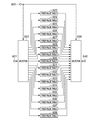
- Fig. 4 is a detailed block diagram illustrating a fixed value selection prediction device in the image coding apparatus according to the first exemplary embodiment of the present invention.
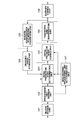
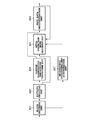
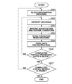
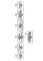
- Fig. 5 is a flowchart illustrating image coding processing in the image coding apparatus according to the first exemplary embodiment of the present invention.
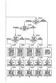
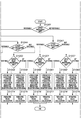
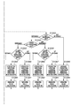
- Fig. 6A is a flowchart illustrating, integrally with Figs. 6B and 6C, detailed processing in step S303 according to the first exemplary embodiment of the present invention.
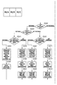
- Fig. 6B is a flowchart illustrating, integrally with Figs.
- Fig. 6A and 6C detailed processing in step S303 according to the first exemplary embodiment of the present invention.
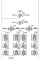
- Fig. 6C is a flowchart illustrating, integrally with Figs. 6A and 6B, detailed processing in step S303 according to the first exemplary embodiment of the present invention.
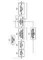
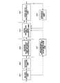
- Fig. 7A is a flowchart illustrating, integrally with Figs. 7B and 7C, processing in step S303 according to a second exemplary embodiment of the present invention.
- Fig. 7B is a flowchart illustrating, integrally with Figs. 7A and 7C, processing in step S303 according to a second exemplary embodiment of the present invention.
- Fig. 7C is a flowchart illustrating, integrally with Figs.
- Fig. 8 is a block diagram illustrating a configuration of an image decoding apparatus according to a third exemplary embodiment of the present invention.
- Fig. 9 is a detailed block diagram illustrating a fixed value selection prediction device in the image coding apparatus according to the third exemplary embodiment of the present invention.
- Fig. 10 is a flowchart illustrating image coding processing in the image coding apparatus according to the third exemplary embodiment of the present invention.
- Fig. 11 is a block diagram illustrating a configuration of an image coding apparatus according to a fourth exemplary embodiment of the present invention.
- FIG. 12 is a block diagram illustrating a configuration of an image coding apparatus according to a fifth exemplary embodiment of the present invention.
- Fig. 13 is a block diagram illustrating a configuration of an image decoding apparatus according to a sixth exemplary embodiment of the present invention.
- Fig. 14 is a detailed block diagram illustrating an intra-prediction mode decoding unit in the image decoding apparatus according to the sixth exemplary embodiment of the present invention.
- Fig. 15 is a detailed block diagram illustrating a fixed value selection prediction device in the image decoding apparatus according to the sixth exemplary embodiment of the present invention.
- Fig. 16 is a flowchart illustrating image decoding processing in the image decoding apparatus according to the sixth exemplary embodiment of the present invention.
- FIG. 17A is a flowchart illustrating, integrally with Figs. 17B and 17C, detailed processing in step S904 according to the sixth exemplary embodiment of the present invention.
- Fig. 17B is a flowchart illustrating, integrally with Figs. 17A and 17C, detailed processing in step S904 according to the sixth exemplary embodiment of the present invention.
- Fig. 17C is a flowchart illustrating, integrally with Figs. 17A and 17B, detailed processing in step S904 according to the sixth exemplary embodiment of the present invention.
- Fig. 18A is a flowchart illustrating, integrally with Figs. 18B and 18C, other processing in step S904 according to a seventh exemplary embodiment of the present invention.
- Fig. 18A is a flowchart illustrating, integrally with Figs. 18B and 18C, other processing in step S904 according to a seventh exemplary embodiment of the present invention.
- Fig. 18A is a flowchart illustrating
- FIG. 18B is a flowchart illustrating, integrally with Figs. 18A and 18C, other processing in step S904 according to a seventh exemplary embodiment of the present invention.
- Fig. 18C is a flowchart illustrating, integrally with Figs. 18A and 18B, other processing in step S904 according to a seventh exemplary embodiment of the present invention.
- Fig. 19 is a block diagram illustrating a configuration of an image decoding apparatus according to an eighth exemplary embodiment of the present invention.
- Fig. 20 is a detailed block diagram illustrating an intra-prediction mode decoding unit in the image coding apparatus according to the eighth exemplary embodiment of the present invention.
- FIG. 21 is a detailed block diagram illustrating a fixed value selection prediction device in the image decoding apparatus according to the eighth exemplary embodiment of the present invention.
- Fig. 22 is a flowchart illustrating image decoding processing in the image decoding apparatus according to the eighth exemplary embodiment of the present invention.
- Fig. 23 is a block diagram illustrating a configuration of the image decoding apparatus according to the eighth exemplary embodiment of the present invention.
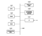
- Fig. 24 is a block diagram illustrating an example hardware configuration of a computer applicable to the image coding apparatuses and image decoding apparatuses according to the exemplary embodiments of the present invention.
- Fig. 25 is a block diagram illustrating H.264.
- Fig. 1 is a block diagram illustrating an image coding apparatus according to a first exemplary embodiment of the present invention.
- a block division unit 101 divides an input image into a plurality of blocks.
- the input image has 8-bit pixel values, the pixel configuration is not limited thereto.
- a processing unit division unit 102 divides each of divisional blocks formed by the block division unit 101 into at least one processing unit equally sized or smaller than the relevant divisional block.
- An intra-prediction mode determination unit 103 determines an intra-prediction mode (intra-frame prediction mode) for each processing unit, and outputs prediction errors.
- An intra-prediction mode coding unit 104 encodes the intra-prediction mode determined by the intra-prediction mode determination unit 103.
- a transform and quantization unit 105 transforms and quantizes the prediction errors of intra-prediction.
- An entropy coding unit 106 encodes a result of the processing by the transform and quantization unit 105.
- a neighboring processing unit determining unit 107 determines whether neighboring processing units of a processing unit subjected to coding are referable.
- An inverse quantization and inverse transform unit 108 performs inverse operations of the prediction-transform-quantization unit 105 to generate the same image as a decoded image.
- a decoded image storage unit 109 stores an output from the inverse quantization and inverse transform unit 108.
- the image coding apparatus inputs moving image data in frame units, it may input still image data for one frame.
- intra-prediction coding processing is performed to simplify descriptions, the processing is not limited thereto.
- the present invention is also applicable to inter-prediction coding processing.
- the block division unit 101 divides image data into blocks formed of 8x8 pixels to simplify descriptions, the processing is not limited thereto.
- a block is divided into four divisional blocks each being horizontally and vertically half in size of the block, the shape and size of the block are not limited thereto.
- the block division unit 101 inputs image data for one frame, and divides it into a plurality of divisional blocks each being formed of 8x8 pixels.
- the processing unit division unit 102 inputs the image data divided into divisional blocks, and further divides each divisional block into at least one processing unit (4x4 pixels) equally sized or smaller than the relevant divisional block.
- the processing unit division unit 102 outputs a position of a processing unit subjected to coding (hereinafter referred to as target processing unit) to the neighboring processing unit determining unit 107.
- the processing unit division unit 102 may output to the neighboring processing unit determination unit 107 vertical and horizontal positions within a frame of the upper left pixel in the target processing unit, the processing is not limited thereto.
- the processing unit division unit 102 may output to the neighboring processing unit determination unit 107 the block number of a target block within a frame and the processing unit number of a target processing unit within the block.
- the neighboring processing unit determining unit 107 determines whether neighboring processing units of the target processing unit are referable based on the position of the target processing unit and the state of the coded processing units.
- the neighboring processing unit determining unit 107 outputs a result of the determination (referability information) to the intra-prediction mode determination unit 103 and the intra-prediction mode coding unit 104.
- the intra-prediction mode determination unit 103 inputs the image data divided into processing units from the processing unit division unit 102, and the referability information from the neighboring processing unit determining unit 107.
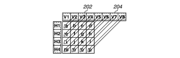
- FIGs. 2A to 2J illustrate example intra-prediction modes.
- a processing unit 201 formed of 4x4 pixels (pixels a to p) is subjected to intra-prediction.
- FIG. 2B illustrate a state of prediction performed in the vertical direction from a pixel group 202 (V1 to V4) adjacently existing to the upside of the processing unit 201.
- This prediction mode is referred to as Vertical prediction mode assigned a prediction mode number 0.
- Fig. 2C illustrates a state of prediction performed in the horizontal direction from a pixel group 203 (H1 to H4) adjacently existing to the left of the processing unit 201.
- This prediction mode is referred to as Horizontal prediction mode assigned a prediction mode number 1.
- 2D illustrates a state of average prediction based on an average for pixel groups adjacently existing to the upside, and left of the processing unit 201.
- An average ave is represented by formula (1).
- This prediction mode is referred to as average prediction mode assigned a prediction mode number 2.
- ave (V1 + V2 + V3 + V4 + H1 + H2 + H3 + H4)/8 ... (1)
- the image coding apparatus calculates an average for pixel groups excluding these pixel groups not referable.
- the image coding apparatus calculates an average for the left pixel group 203 (H1, H2, H3, and H4).
- a predetermined average ave (128) is given to the processing unit at the top left corner of the frame.
- Fig. 2E illustrates a state of prediction performed in the diagonally downward left direction from the pixel group 202 (V2 to V4) adjacently existing to the upside and a pixel group 204 (V5 to V8) adjacently existing to the upper right of the processing unit 201.
- This prediction mode is referred to as Diagonal_Down_Left prediction mode assigned a prediction mode number 3.
- Fig. 2F illustrates a state of prediction performed in the diagonally downward right direction from the pixel group 202 (V1, V2) adjacently existing to the upside, a pixel (C0) adjacently existing to the upper left, and a pixel group 203 (H1, H2) adjacently existing to the left of the processing unit 201.
- This prediction mode is referred to as Diagonal_Down_Right prediction mode assigned a prediction mode number 4.
- Fig. 2G illustrates a state of prediction performed more vertically in the diagonally downward right direction from the pixel group 202 (V1 to V3) adjacently existing to the upside and the pixel (C0) adjacently existing to the upper left of the processing unit 201.
- This prediction mode is referred to as Vertical_Right prediction mode assigned a prediction mode number 5.
- Fig. 2H illustrates a state of prediction performed more horizontally in the diagonally downward right direction from the pixel group 203 (H1 to H3) adjacently existing to the left and the pixel (C0) adjacently existing to the upper left of the processing unit 201.
- This prediction mode is referred to as Horizontal_Down prediction mode assigned a prediction mode number 6.
- Fig. 2I illustrates a state of prediction performed more vertically in the diagonally downward left direction from the pixel group 202 (V2 to V4) adjacently existing to the upside and a pixel 204 (V5) to the upper right of the processing unit 201.
- This prediction mode is referred to as Vertical_Left prediction mode assigned a prediction mode number 7.
- Fig. 2J illustrates a state of prediction performed more horizontally in the diagonally upward right direction from the pixel group 203 (from H2 to H4) adjacently existing to the left and a pixel 206 (H5) adjacently existing to the lower left of the processing unit 201.
- This prediction mode is referred to as Horizontal_Up prediction mode assigned a prediction mode number 8.
- the image coding apparatus perform prediction by selecting predicted values from a predetermined fixed value group.
- This prediction mode is referred to as fixed value selection prediction mode assigned a prediction mode number 9.
- the intra-prediction mode determination unit 103 determines an optimum intra-prediction mode out of the above-mentioned ten different intra-prediction modes, and outputs the intra-prediction mode to the intra-prediction mode coding unit 104 and the transform and quantization unit 105.
- the intra-prediction mode coding unit 104 stores the intra-prediction mode as a mode of intra-prediction for a coded processing unit so that the intra-prediction mode is referred to in subsequent determinations.
- the neighboring processing unit determining unit 107 represents whether the following five different processing units are referable by using respective pieces of 1-bit information.
- Processing unit including the upper pixel group 202 Processing unit including the left pixel group 203 (3) Processing unit including an upper left pixel 205 (4) Processing unit including the lower left pixel 206 (5) Processing unit including the upper right pixel 204
- the image coding apparatus sets the corresponding 1-bit information to 1. Otherwise, when the processing unit not referable, the image coding apparatus sets the corresponding 1-bit information to 0.
- These five pieces of 1-bit information for respective processing units are sequentially arranged into 5-bit information which is referred to as referability information.
- processing units to be referred to and the bit configuration are not limited thereto.
- the intra-prediction mode coding unit 104 inputs the referability information from the neighboring processing unit determining unit 107 and the intra-prediction mode from the intra-prediction mode determination unit 103, and encodes the intra-prediction mode by using a predetermined method to acquire intra-prediction mode coded data.
- Fig. 3 is a detailed block diagram illustrating the intra-prediction mode determination unit 103.
- the intra-prediction mode determination unit 103 inputs data i.e., pixel values of processing unit from the processing unit division unit 102.
- the intra-prediction mode determination unit 103 inputs a result of neighboring processing block decoding, i.e., pixel values of referable pixels from the decoded image storage unit 109.
- Prediction devices 133 to 142 perform intra-prediction. Each prediction device inputs pixel values of processing unit from the terminal 130, referable pixels from the terminal 131, and the referability information for neighboring processing units from the neighboring processing unit determining unit 107.
- a Vertical prediction device 133 performs Vertical prediction. Specifically, when the first bit of the referability information is 1, the Vertical prediction device 133 performs prediction in the vertical direction to generate prediction errors. Otherwise, this prediction device performs no operation and hence outputs no data.
- a Horizontal prediction device 134 performs Horizontal prediction. Specifically, when the second bit of the referability information is 1, the Horizontal prediction device 134 performs prediction in the horizontal direction to generate prediction errors. Otherwise, this prediction device performs no operation and hence outputs no data.
- a Diagonal_Down_Left prediction device 135 performs Diagonal_Down_Left prediction. Specifically, when both the first and fifth bits of the referability information are 1, the Diagonal_Down_Left prediction device 135 performs prediction in the diagonally downward left direction to generate prediction errors. Otherwise, this prediction device performs no operation and hence outputs no data.
- a Diagonal_Down_Right prediction device 136 performs Diagonal_Down_Right prediction. Specifically, when all of the first, second, and third bits of the referability information are 1, the Diagonal_Down_Right prediction device 136 performs prediction in the diagonally downward right direction to generate prediction errors. Otherwise, this prediction device performs no operation and hence outputs no data.
- a Vertical_Right prediction device 137 performs Vertical_Right prediction. Specifically, when both the first and third bits of the referability information are 1, the Vertical_Right prediction device 137 performs prediction more vertically in the diagonally downward right direction to generate prediction errors. Otherwise, this prediction device performs no operation and hence outputs no data.
- a Horizontal_Down prediction device 138 performs Horizontal_Down prediction. Specifically, when both the second and third bits of the referability information are 1, the Horizontal_Down prediction device 138 performs prediction more horizontally in the diagonally downward right direction to generate prediction errors. Otherwise, this prediction device performs no operation and hence outputs no data.
- a Vertical_Left prediction device 139 performs Vertical_Left prediction. Specifically, when both the first and fifth bits of the referability information are 1, the Vertical_Left prediction device 139 performs prediction more vertically in the diagonally downward left direction to generate prediction errors. Otherwise, this prediction device performs no operation and hence outputs no data.
- a Horizontal_Up prediction device 140 performs Horizontal_Up prediction. Specifically, when both the second and fourth bits of the referability information are 1, the Horizontal_Up prediction device 140 performs prediction more horizontally in the diagonally upward right direction to generate prediction errors. Otherwise, this prediction device performs no operation and hence outputs no data.
- An average prediction device 141 performs average prediction. Specifically, when both the first and second bits of the referability information are 1, the average prediction device 141 performs average prediction based on the formula (1) to generate prediction errors. Otherwise, this prediction device outputs a fixed value of 128.
- a fixed value selection prediction device 142 performs fixed value selection prediction. Specifically, when any one bit of the referability information is 0, the fixed value selection prediction device 142 outputs a fixed value that gives minimum prediction errors out of predetermined fixed values, and the minimum prediction errors based on the fixed values. Otherwise, this prediction device performs no operation and hence outputs no data.
- a prediction mode determination device 143 inputs prediction errors from respective prediction devices, calculates sums of absolute values (absolute value sums) of prediction errors, selects a prediction device that produces a minimum absolute value sum, and outputs the prediction mode of the relevant prediction device and the relevant minimum prediction errors.
- the basis of determination is not limited to the absolute value sum.
- the intra-prediction mode determination unit 103 outputs an intra-prediction mode code to the entropy coding unit 106 in Fig. 1.
- the intra-prediction mode determination unit 103 outputs predicted values to the transform and quantization unit 105 in Fig. 1.
- Fig. 4 is a detailed block diagram illustrating the fixed value selection prediction device 142.
- the fixed value selection prediction device 142 Via a terminal 150, the fixed value selection prediction device 142 inputs the referability information calculated by the neighboring processing unit determining unit 107 in Fig. 1.
- the fixed value selection prediction device 142 Via a terminal 167, the fixed value selection prediction device 142 inputs the pixel values of processing unit input via the terminal 130 in Fig. 3.
- Fixed value tables 151 to 166 stores fixed values. Each fixed value table stores a plurality of fixed values based on the referability information. The number of fixed values corresponds to the number of prediction modes that cannot be used when one or more predetermined processing units are not referable. Specifically, bits assigned to prediction modes made unusable when predetermined processing units are not referable are assigned fixed values which may possibly minimize the minimum prediction errors instead of the relevant prediction modes.
- the fixed value table 151 stores fixed values to be used when the referability information is 11110. Specifically, when the upper right processing unit is not referable, the fixed value table 151 stores two fixed values such as 0 and 255. The two fixed values are not limited thereto, and may be 64 and 192 for example.
- the fixed value table 152 stores fixed values to be used when the referability information is 11101. Specifically, when the left processing unit is not referable, the fixed value table 152 stores one fixed value such as 128.
- the fixed value table 153 stores fixed values to be used when the referability information is 11100. Specifically, when the upper right and lower left processing units are not referable, the fixed value table 153 stores three predicted values such as 64, 128 and 192 for example.
- the fixed value table 154 stores fixed values to be used when the referability information is 11011. Specifically, when the upper left processing unit is not referable, the fixed value table 154 stores three fixed values such as 64, 128 and 192 for example.
- the fixed value table 155 stores fixed values to be used when the referability information is 11010. Specifically, when the upper left and upper right processing units are not referable, the fixed value table 155 stores five fixed values such as 0, 64, 128, 192, and 255 for example.
- the fixed value table 156 stores fixed values to be used when the referability information is 11001. Specifically, when the upper left and lower left processing units are not referable, the fixed value table 156 stores four fixed values such as 0, 85, 170, and 255 for example.
- the fixed value table 157 stores fixed values to be used when the referability information is 11000. Specifically, when the upper left, lower left, and upper right processing units are not referable, the fixed value table 157 stores six fixed values such as 0, 51, 102, 153, 204, and 255 for example.
- the fixed value table 158 stores fixed values to be used when the referability information is 10111 or 10101. Specifically, when the left processing unit is not referable or when the left and lower left processing units are not referable, the fixed value table 158 stores four fixed values such as 0, 85, 170, and 255 for example.
- the fixed value table 159 stores fixed values to be used when the referability information is 10110 or 10100. Specifically, when the left and upper right processing units are not referable or when the left, lower left, and upper right processing units are not referable, the fixed value table 159 stores six fixed values such as 0, 51, 102, 153, 204, and 255 for example.
- the fixed value table 160 stores fixed values to be used when the referability information is 10011 or 10001. Specifically, when the left and upper left processing units are not referable or when the left, upper left, and lower left processing units are not referable, the fixed value table 160 stores five fixed values such as 0, 64, 128, 192, and 255 for example.
- the fixed value table 161 stores fixed values to be used when the referability information is 10010 or 10000. Specifically, when only the upper and upper left processing units or only the upper processing unit is referable or when only the upper processing unit is referable, the fixed value table 161 stores seven fixed values such as 0, 43, 85, 128, 170, 213, and 255 for example.
- the fixed value table 162 stores fixed values to be used when the referability information is 01111 or 01110. Specifically, when the upper processing unit is not referable or when the upper and upper right processing units are not referable, the fixed value table 162 stores five fixed values such as 0, 64, 128, 192, and 255 for example.
- the fixed value table 163 stores fixed values to be used when the referability information is 01101 or 01100. Specifically, when the upper and lower left processing units are not referable or when the upper, lower left, and upper right processing units are not referable, the fixed value table 163 stores six fixed values such as 0, 51, 102, 153, 204, and 255 for example.
- the fixed value table 164 stores fixed values to be used when the referability information is 01011 or 01010. Specifically, when the upper and upper left processing units are not referable or when the upper, upper left, and upper right processing units are not referable, the fixed value table 164 stores six fixed values such as 0, 51, 102, 153, 204, and 255 for example.
- the fixed value table 165 stores fixed values to be used when the referability information is 01001 or 01000. Specifically, when only the left processing unit is referable or when only the left and upper right processing units are referable, the fixed value table 165 stores seven fixed values such as 0, 43, 85, 128, 170, 213, and 255 for example.
- the fixed value table 166 stores fixed values to be used when the referability information is 00111, 00110, 00101, 00100, 00011, 00010, 00001, or 00000. Specifically, when both the upper and left processing units are not referable, the fixed value table 166 stores eight fixed values such as 0, 36, 73, 109, 146, 182, 219, and 255 for example.
- the number of fixed values that can be stored in each fixed value table may naturally be equal to or smaller than the above-mentioned number.
- Fixed value tables assigned the same number of fixed values may be an identical fixed value table.
- a selector 168 selects a relevant fixed value table as a source based on the referability information input from the terminal 150.
- a prediction error calculation device 169 calculates prediction errors based on pixel values input from the terminal 167 with respect to each input fixed value.
- a predicted value determination device 170 selects minimum prediction errors out of prediction errors for respective fixed values, and outputs the relevant predicted values. Via a terminal 171, the fixed value selection prediction device 142 outputs the selected predicted values and the minimum prediction errors to the prediction mode determination device 143 in Fig. 3.
- the selector 168 selects a relevant fixed value table as a source based on the referability information input from the terminal 150. For example, when referability information 11001 is input from the terminal 150, the selector 168 selects the fixed value table 156.
- the prediction error calculation device 169 outputs the calculated prediction errors Ei and the corresponding fixed values Pi to the predicted value determination device 170.
- the predicted value determination device 170 calculates respective absolute value sums Ai based on the prediction errors Ei(x,y).
- the predicted value determination device 170 acquires prediction errors Emin(x,y) and a fixed value Pmin that give a minimum absolute value sum Ai.
- the predicted value determination device 170 outputs the relevant prediction errors Emin(x,y) and fixed value Pmin to the prediction mode determination device 143 in Fig. 3 via the terminal 171.
- each prediction device performs or does not perform an operation referring to the referability information (input from the neighboring processing unit determining unit 107) for each processing unit to calculate prediction errors in each prediction mode.
- the prediction mode determination device 143 inputs prediction errors from operative prediction devices, and fixed values for prediction error calculation from the fixed value selection prediction device 142. Then, the prediction mode determination device 143 calculates absolute value sums of prediction errors input from respective prediction devices to determine prediction errors that give a minimum absolute value sum.
- the prediction mode determination device 143 determines as intra-prediction mode the prediction mode of the prediction device that produced the relevant prediction errors, and outputs the relevant prediction mode number to the intra-prediction mode coding unit 104.
- the prediction mode determination device 143 also outputs the relevant prediction errors to the transform and quantization unit 105 via the terminal 145.
- the intra-prediction mode coding unit 104 encodes the input prediction mode number.
- the intra-prediction mode coding unit 104 predicts an intra-prediction mode of the target processing unit based on coded neighboring intra-prediction modes.
- the intra-prediction mode coding unit 104 encodes a prediction mode flag to 1. Otherwise, it encodes the prediction mode flag to 0.
- the intra-prediction mode coding unit 104 encodes predetermined prediction modes, excluding the coded neighboring intra-prediction modes and the fixed value selection prediction mode, into a 3-bit code.
- the intra-prediction mode coding unit 104 When prediction mode number 9 is input as an intra-prediction mode, i.e., when the fixed value selection prediction is selected, the intra-prediction mode coding unit 104 encodes the input fixed value.
- the intra-prediction mode coding unit 104 acquires the referability information from the neighboring processing unit determining unit 107.
- the intra-prediction mode coding unit 104 determines unusable prediction modes based on the acquired referability information. Table 1 lists unusable prediction mode numbers for each value of the referability information.
- prediction mode numbers 4 and 8 are unusable.
- the fixed value table 156 storing four predicted values is used.
- four predicted values 0, 85, 170, and 255 are sequentially assigned to respective prediction mode numbers. Therefore, prediction mode numbers 4, 5, 6, and 8 are assigned predicted values of 0, 85, 170, and 255, respectively.
- the intra-prediction mode coding unit 104 encodes the prediction mode numbers acquired in this way into a 3-bit code.
- the intra-prediction mode coding unit 104 outputs the coded data to the entropy coding unit 106.
- the intra-prediction mode determination unit 103 outputs the calculated prediction errors to the transform and quantization unit 105.
- the transform and quantization unit 105 transforms and quantizes the prediction errors.
- the entropy coding unit 106 encodes quantized coefficient data, and outputs as a bit stream the coded coefficient data together with the intra-prediction mode coded data generated by the intra-prediction mode coding unit 104.
- Fig. 5 is a flowchart illustrating image coding processing in the image coding apparatus according to the first exemplary embodiment of the present invention.
- the block division unit 101 divides input frame-unit image data into a plurality of divisional blocks each being formed of 8x8 pixels.
- step S302 the processing unit division unit 102 divides each of the divisional blocks (formed by the block division unit 101) into at least one processing unit equally sized or smaller than the relevant divisional block.
- step S303 the intra-prediction mode determination unit 103 determines an intra-prediction mode of the target processing unit, calculates prediction errors for the target processing unit, and stores the determined intra-prediction mode.
- the intra-prediction mode coding unit 104 encodes the prediction mode determined by the intra-prediction mode determination unit 103. This processing will be described in detail below.
- step S304 the transform and quantization unit 105 transforms and quantizes the input prediction errors to generate quantized coefficient data.
- step S305 the entropy coding unit 106 applies entropy coding to the quantized coefficient data, and outputs the coded data together with the intra-prediction mode code.
- the inverse quantization and inverse transform unit 108 applies inverse quantization and inverse transform to the quantized coefficient data.
- the decoded image storage unit 109 stores the resultant data for use in subsequent processing unit prediction.
- step S306 the image coding apparatus determines whether coding processing is completed for all processing units in the block. When coding processing is completed for all processing units in the block (YES in step S306), the processing proceeds to step S307. Otherwise, coding processing is not completed for all processing units in the block (NO in step S306), processing returns to step S302 to process the following processing unit.
- step S307 the image coding apparatus determines whether coding processing is completed for all blocks in the frame. When coding processing is completed for all blocks in the frame (YES in step S307), the processing ends. Otherwise, when coding processing is not completed for all blocks in the frame (NO in step S307), the processing returns to step S301 to process the following block.
- Figs. 6A, 6B, and 6C are flowcharts integrally illustrating detailed processing in step S303.
- the neighboring processing unit determining unit 107 determines whether each of predetermined neighboring processing units of the target processing unit is referable.
- step S401 the neighboring processing unit determination unit 107 determines whether a processing unit existing to the upside of the target processing unit is referable.
- the processing proceeds to step S402. Otherwise, when the processing unit existing to the upside of the target processing unit is not referable (NOT REFERABLE in step S401), the processing proceeds to step S403.
- step S402 the neighboring processing unit determination unit 107 determines whether a processing unit existing to the left of the target processing unit is referable. When the processing unit existing to the left of the target processing unit is referable (REFERABLE in step S402), the processing proceeds to step S440. Otherwise, when the processing unit existing to the left of the target processing unit is not referable (NOT REFERABLE in step S402), the processing proceeds to step S441.
- step S403 the neighboring processing unit determination unit 107 also determines whether a processing unit existing to the left of the target processing unit is referable. When the processing unit existing to the left of the target processing unit is referable (REFERABLE in step S403), the processing proceeds to step S442. Otherwise, when the processing unit existing to the left of the target processing unit is not referable (NOT REFERABLE in step S403), the processing proceeds to step S412.
- the neighboring processing unit determination unit 107 determines whether a processing unit existing to the upper left of the target processing unit is referable. When the processing unit existing to the upper left of the target processing unit is referable (REFERABLE in steps S440, S441, and S442), the processing proceeds to step S443, S451, and S445, respectively. Otherwise, when the processing unit existing to the upper left of the target processing unit is not referable (NOT REFERABLE in steps S440, S441, and S442), the processing proceeds to step S444, S452, and S446, respectively.
- steps S443 and S444 the neighboring processing unit determination unit 107 determines whether a processing unit existing to the lower left of the target processing unit is referable. When the processing unit existing to the lower left of the target processing unit is referable (REFERABLE in steps S443 and S444), the processing proceeds to steps S447 and S449, respectively. Otherwise, when the processing unit existing to the lower left of the target processing unit is not referable (NOT REFERABLE in steps S443 and S444), the processing proceeds to steps S448 and S450, respectively.
- the neighboring processing unit determination unit 107 determines whether a processing unit existing to the upper right of the target processing unit is referable.
- the neighboring processing unit determination unit 107 determines an optimum intra-prediction mode for the relevant processing unit out of all intra-prediction modes excluding the fixed value selection prediction mode (average prediction mode and eight directional prediction modes). Although it is common that an optimum intra-prediction mode is determined by calculating prediction errors for each intra-prediction mode and selecting a prediction mode that generated predicted values giving minimum prediction errors as described above, the processing is not limited thereto.
- step S405 the intra-prediction mode coding unit 104 encodes the determined intra-prediction mode information into a 1-bit prediction mode flag and a 3-bit intra-prediction mode code as described above.
- the referability information indicates that processing units existing to the upside, left, upper left, and lower left of the target processing unit are referable, and that a processing unit existing to the upper right of the target processing unit is not referable.
- the Diagonal_Down_Left prediction mode and the Vertical_Left prediction mode are unusable. Prediction errors are calculated by using prediction modes other than these unusable modes.
- step S454 the intra-prediction mode determination unit 103 selects an intra-prediction mode that gives minimum prediction errors out of prediction errors calculated by six directional intra-prediction modes selectable in this situation, the average prediction mode, and the fixed value selection prediction mode.
- the referability information indicates that processing units existing to the upside, left, upper left, and upper right of the target processing unit are referable, and that a processing unit existing to the lower left of the target processing unit is not referable.
- the Horizontal_Up prediction mode is unusable. Prediction errors are calculated by using prediction modes other than this unusable mode.
- step S457 the intra-prediction mode determination unit 103 selects an intra-prediction mode that gives minimum prediction errors out of prediction errors calculated by seven directional intra-prediction modes selectable in this situation, the average prediction mode, and the fixed value selection prediction mode.
- the referability information indicates that processing units existing to the upside, left, and upper left of the target processing unit are referable, and that processing units existing to the lower left, and upper right of the target processing unit are not referable.
- the Diagonal_Down_Left prediction mode, the Vertical_Left prediction mode, and the Horizontal_Up prediction mode are unusable. Prediction errors are calculated by using prediction modes other than these unusable modes.
- step S460 the intra-prediction mode determination unit 103 selects an intra-prediction mode that gives minimum prediction errors out of prediction errors calculated by five directional intra-prediction modes selectable in this situation, the average prediction mode, and the fixed value selection prediction mode.
- the referability information indicates that processing units existing to the upside, left, lower left, and upper right of the target processing unit are referable, and that a processing unit existing to the upper left of the target processing unit are not referable.
- the Diagonal_Down_Right prediction mode, the Vertical_Right prediction mode, and the Horizontal_Down prediction mode are unusable. Prediction errors are calculated by using prediction modes other than these unusable modes.
- step S463 the intra-prediction mode determination unit 103 selects an intra-prediction mode that gives minimum prediction errors out of prediction errors calculated by five directional intra-prediction modes selectable in this situation, the average prediction mode, and the fixed value selection prediction mode.
- the referability information indicates that processing units existing to the upside, left, and upper left of the target processing unit are referable, and that processing units existing to the lower left, and upper right of the target processing unit are not referable.
- the Diagonal_Down_Left prediction mode, the Diagonal_Down_Right prediction mode, the Vertical_Right prediction mode, the Horizontal_Down prediction mode, and the Vertical_Left prediction mode are unusable. Prediction errors are calculated by using prediction modes other than these unusable modes.
- step S466 the intra-prediction mode determination unit 103 selects an intra-prediction mode that gives minimum prediction errors out of prediction errors calculated by three directional intra-prediction modes selectable in this situation, the average prediction mode, and the fixed value selection prediction mode.
- the referability information indicates that processing units to upside, left, and upper right of the target processing unit are referable, and that processing units existing to the upper left, and lower left of the target processing unit are not referable.
- the Diagonal_Down_Right prediction mode, the Vertical_Right prediction mode, the Horizontal_Down prediction mode, and the Horizontal_Up prediction mode are unusable. Prediction errors are calculated by using prediction modes other than these unusable modes.
- step S469 the intra-prediction mode determination unit 103 selects an intra-prediction mode that gives minimum prediction errors out of prediction errors calculated by four directional intra-prediction modes selectable in this situation, the average prediction mode, and the fixed value selection prediction mode.
- step S471 the referability information indicates that processing units existing to the upside, and left of the target processing unit are referable, and that processing units existing to the upper left, lower left, and upper right of the target processing unit are not referable. In this case, only the Vertical prediction mode and the Horizontal prediction mode are usable. Prediction errors are calculated by using these prediction modes.
- step S472 the intra-prediction mode determination unit 103 selects an intra-prediction mode that gives minimum prediction errors out of prediction errors calculated by two directional intra-prediction modes selectable in this situation, the average prediction mode, and the fixed value selection prediction mode.
- the referability information indicates that processing units existing to the upside, upper left, and upper right of the target processing unit are referable, and that a processing unit existing to the left of the target processing unit is not referable.
- the Horizontal prediction mode, the Diagonal_Down_Right prediction mode, the Horizontal_Down prediction mode, and the Horizontal_Up prediction mode are unusable. Prediction errors are calculated by using prediction modes other than these unusable modes.
- step S475 the intra-prediction mode determination unit 103 selects an intra-prediction mode that gives minimum prediction errors out of prediction errors calculated by four directional intra-prediction modes selectable in this situation, the average prediction mode, and the fixed value selection prediction mode.
- the referability information indicates that processing units existing to the upside, and upper left of the target processing unit are referable, and that processing units existing to the left, and upper right of the target processing unit are not referable.
- the Vertical prediction mode and the Vertical_Right prediction mode are usable. Prediction errors are calculated by using these prediction modes.
- step S4708 the intra-prediction mode determination unit 103 selects an intra-prediction mode that gives minimum prediction errors out of prediction errors calculated by two directional intra-prediction modes selectable in this situation, the average prediction mode, and the fixed value selection prediction mode.
- step S480 the referability information indicates that processing units existing to the upside, and upper right of the target processing unit are referable, and that processing units existing to the left, and upper left of the target processing unit are not referable.
- the Vertical prediction mode, the Diagonal_Down_Left prediction mode, and the Vertical_Left prediction mode are usable. Prediction errors are calculated by using these prediction modes.
- step S481 the intra-prediction mode determination unit 103 selects an intra-prediction mode that gives minimum prediction errors out of prediction errors calculated by three directional intra-prediction modes selectable in this situation, the average prediction mode, and the fixed value selection prediction mode.
- step S483 the referability information indicates that a processing unit existing to the upside of the target processing unit is referable, and that processing units existing to the left, upper left, and upper right of the target processing unit are not referable. In this case, only the Vertical prediction mode is usable. Prediction errors are calculated by using this prediction mode.
- step S484 the intra-prediction mode determination unit 103 selects an intra-prediction mode that gives minimum prediction errors out of prediction errors calculated by vertical directional intra-prediction modes selectable in this situation, the average prediction mode, and the fixed value selection prediction mode.
- the referability information indicates that processing units existing to the left, upper left, and lower left of the target processing unit are referable, and that a processing unit existing to the upside of the target processing unit is not referable.
- the Horizontal prediction mode, the Horizontal_Down prediction mode, and Horizontal_Up prediction mode are usable. Prediction errors are calculated by using these prediction modes.
- step S487 the intra-prediction mode determination unit 103 selects an intra-prediction mode that gives minimum prediction errors out of prediction errors calculated by three directional intra-prediction modes selectable in this situation, the average prediction mode, and the fixed value selection prediction mode.
- the referability information indicates that processing units existing to the left, and upper left of the target processing unit are referable, and that processing units existing to the upside, and lower left of the target processing unit are not referable. In this case, only the Horizontal prediction mode and the Horizontal_Down prediction mode are referable. Prediction errors are calculated by using these prediction modes.
- step S490 the intra-prediction mode determination unit 103 selects an intra-prediction mode that gives minimum prediction errors out of prediction errors calculated by two directional intra-prediction modes selectable in this situation, the average prediction mode, and the fixed value selection prediction mode.
- the referability information indicates that processing units existing to the left, and lower left of the target processing unit are referable, and that processing units existing to the upside, and upper left of the target processing units are not referable. In this case, only the Horizontal prediction mode and the Horizontal_Up prediction mode are usable. Prediction errors are calculated by using these prediction modes.
- step S493 the intra-prediction mode determination unit 103 selects an intra-prediction mode that gives minimum prediction errors out of prediction errors calculated by two directional intra-prediction modes selectable in this situation, the average prediction mode, and the fixed value selection prediction mode.
- step S495 the referability information indicates that a processing unit existing to the left of the target processing unit is referable, and that processing units existing to the upside, upper left, and lower left of the target processing unit are not referable. In this case, only the Horizontal prediction mode is usable. Prediction errors are calculated by using this prediction mode.
- step S496 the intra-prediction mode determination unit 103 selects an intra-prediction mode that gives minimum prediction errors out of prediction errors calculated by horizontal directional intra-prediction modes selectable in this situation, the average prediction mode, and the fixed value selection prediction mode.
- step S412 the referability information indicates that all of neighboring processing units are not referable.
- prediction errors are calculated by using the average prediction mode having a predicted value of 128 or the fixed value selection prediction mode.
- step S413 the intra-prediction mode determination unit 103 selects an intra-prediction mode that gives minimum prediction errors out of prediction errors calculated by the above-mentioned average prediction mode and fixed value selection prediction mode.
- the intra-prediction mode coding unit 104 encodes the intra-prediction mode.
- the intra-prediction mode coding unit 104 encodes relevant prediction mode numbers.
- the intra-prediction mode coding unit 104 encodes unusable prediction mode numbers assigned respective predicted values.
- the intra-prediction mode coding unit 104 selects and encodes fixed values instead of unusable intra-prediction modes, remarkably restraining prediction errors in intra-prediction.
- a divisional block is formed of 8x8 pixels and a processing unit is formed of 4x4 pixels
- the pixel configuration is not limited thereto.
- the block size can be changed to 16x16 pixels.
- the shape of a block is not limited to a square, and may be a rectangle such as 8x4 pixels.
- the essence of the present invention remains unchanged by the block shape.
- predictions are performed based only on 4x4 pixels, it is obvious that, when a block is not divided and predictions are performed based on 8x8 pixels, the fixed value selection prediction can be similarly performed based on the state of neighboring blocks.
- pixels in neighboring processing units directly or diagonally contacting the target unit are referred to, the processing is not limited thereto.
- the processing is not limited thereto.
- intra-predictions are performed referring to the upper pixel group 202, the left pixel group 203, the upper right pixel group 204, the upper right pixel 205, and the lower left pixel 206
- the processing is not limited thereto.
- predictions are performed with an angle of 45 degrees
- the processing is not limited thereto.
- the angle may be divided in 15-degree units.
- a bit-assigned code is used, the processing is not limited thereto.
- coding referring to prediction modes of processing units processed before or coding based on arithmetic codes may be performed.
- the order of referability determination is not limited to the above-mentioned one.
- referability determination may be started from the left processing unit.
- the block size, shape, and prediction direction are not limited to the above-mentioned ones.
- predicted values are assigned to all of unusable intra-prediction mode numbers, the processing is not limited thereto. Not all of unusable intra-prediction mode numbers may be unusable. Further, these unusable intra-prediction mode numbers may be assigned to other purposes.
- step S303 conditional branch and coding are performed for all of the upper pixel group 202, the left pixel group 203, the upper right pixel groups 204, the upper right pixels 205, and the lower left pixels 206.
- Figs. 7A, 7B, and 7C are flowcharts integrally illustrating detailed processing in step S303 (Fig. 5) according to the second exemplary embodiment of the present invention.
- elements having the same function as those in the first exemplary embodiment are assigned the same reference numeral, and duplicated descriptions will be omitted.
- the neighboring processing unit determination unit 107 determines whether both processing units existing to the lower left, and upper right of the target processing unit are referable.
- step S459 similar to the first exemplary embodiment, predictions are performed assuming that both the lower left and upper right processing units are not referable. Specifically, the Diagonal_Down_Left prediction mode, the Vertical_Left prediction mode, and the Horizontal_Up prediction mode are unusable. Prediction errors are calculated by using prediction modes other than these unusable modes.
- steps S471, S477, S483, S489, and S495 predictions are performed assuming that both the lower left and upper right processing units are not referable.
- the selector 168 in Fig. 4 selects a relevant fixed value table as a source based on the referability information. When the higher 3 bits of the referability information are 111 and either one of the lower 2 bits thereof is 0, the selector 168 selects the input from the fixed value table 153.
- the selector 168 selects the input from the fixed value table 154. When either one of the lower 2 bits is 0, the selector 168 selects the input from the fixed value table 157. When the higher 3 bits of the referability information are 101 and the lower 2 bits thereof are 11, the selector 168 selects the input from the fixed value table 158. When either one of the lower 2 bits is 0, the selector 168 selects the input from the fixed value table 159. When the higher 3 bits of the referability information are 100 and the lower 2 bits thereof are 11, the selector 168 selects the input from the fixed value table 160. When either one of the lower 2 bits is 0, the selector 168 selects the input from the fixed value table 161.
- the selector 168 selects the input from the fixed value table 162. When either one of the lower 2 bits is 0, the selector 168 selects the input from the fixed value table 163. When the higher 3 bits of the referability information are 010 and the lower 2 bits thereof are 11, the selector 168 selects the input from the fixed value table 164. When either one of the lower 2 bits is 0, the selector 168 selects the input from the fixed value table 165. When the higher 3 bits of the referability information are 000, the selector 168 selects the input from the fixed value table 166. Therefore, the fixed value tables 151, 152, 155, and 156 are not used.
- Fig. 8 is a block diagram illustrating an image coding apparatus according to a third exemplary embodiment of the present invention. Referring to Fig. 8, elements having the same function as those in the first exemplary embodiment (Fig. 1) are assigned the same reference numeral, and duplicated descriptions will be omitted.
- An image analysis unit 200 analyzes an input image and calculates fixed values to be used for fixed value selection prediction. Although, in the present exemplary embodiment, the image analysis unit 200 calculates an intra-processing-unit average and analyzes an image for each processing unit, the processing is not limited thereto.
- An intra-prediction mode determination unit 203 differs from the intra-prediction mode determination unit 103 according to the first exemplary embodiment in that the intra-prediction mode determination unit 203 inputs data from the image analysis unit 200.
- a fixed value coding unit 206 encodes fixed values calculated by the image analysis unit 200.
- the image analysis unit 200 inputs frame data and calculates an average for each processing unit (intra-processing-unit average).
- the image analysis unit 200 calculates an intra-processing-unit average and calculates referability information on the relevant processing unit.
- the image analysis unit 200 generates a histogram of an average for each piece of referability information. For example, when the referability information is 11110, the image analysis unit 200 generates a histogram Hist_11110 of the calculated average. When the higher 2 bits of the referability information are 00, the image analysis unit 200 generates a histogram Hist_00 of the calculated average since the fixed value table 166 is used even when the lower 3 bits changes.
- the image analysis unit 200 generates other histograms of averages calculated corresponding to fixed value tables based on the referability information.
- the image analysis unit 200 calculates the same number of fixed values as the number of unusable prediction mode numbers. For example, when the referability information is 11001, the image analysis unit 200 calculates four fixed values.
- the method for calculating fixed values is not limited to any particular method, the image analysis unit 200 determines them, for example, by selecting four frequently used local maximum values in the histogram or by selecting an average of close local maximum values when there are many local maximum values.
- the image analysis unit 200 When calculation of fixed values used for selection with the referability information is completed, the image analysis unit 200 outputs the calculated fixed values to the intra-prediction mode determination unit 203 and the fixed value coding unit 206.
- Fig. 9 is a detailed block diagram illustrating the intra-prediction mode determination unit 203. Referring to Fig. 9, elements having the same function as those in the first exemplary embodiment (Fig. 4) are assigned the same reference numeral, and duplicated descriptions will be omitted.
- a selector 251 inputs predicted values from the image analysis unit 200 and selects a relevant fixed value table as a destination based on the referability information input from the terminal 150.
- the intra-prediction mode determination unit 203 sequentially inputs the referability information from the terminal 150.
- Fixed values input from the terminal 250 are stored in each fixed value table based on the referability information. For example, when the referability information is 11001, the selector 251 selects the fixed value table 156 and stores four predicted values in the fixed value table 156.
- the present exemplary embodiment differs from the first exemplary embodiment in that predicted values read from fixed value tables at the time of coding are not predetermined fixed values.
- the fixed value coding unit 206 encodes predicted values input from the image analysis unit 200.
- the coding method is not limited to any particular method. Predicted values may be transmitted as they are, or difference values from a smaller value may be transmitted. The coded fixed values for each piece of referability information are output to the outside.
- Fig. 10 is a flowchart illustrating image coding processing in the image coding apparatus according to the third exemplary embodiment of the present invention.
- elements having the same function as those in the first exemplary embodiment (Fig. 5) are assigned the same reference numeral, and duplicated descriptions will be omitted.
- step S1301 the image coding apparatus calculates an average for processing units at an edge of a slice or frame, and generate a histogram.
- step S1302 the image coding apparatus calculates fixed values selected from the calculated histogram corresponding to the referability information used in fixed value selection prediction.
- step S1303 the image coding apparatus stores calculated fixed values in the fixed value tables in the intra-prediction mode determination unit 203.
- the image coding apparatus performs coding processing similar to the first exemplary embodiment of the present invention.
- step S1304 the image coding apparatus encodes fixed values used in each fixed value selection prediction mode, and outputs them to the outside.
- a plurality of pieces of referability information are collected and fixed values to be stored in fixed value tables are calculated
- the processing is not limited thereto.
- it is also possible to generate a histogram for each piece of referability information store fixed values in the fixed value tables based on the referability information, and read the fixed values from the fixed value tables based on the referability information.
- fixed values to be stored in the fixed value table 166 are produced from the histogram Hist_00, it is also possible to generate eight histograms and acquire respective fixed values according to the lower 3 bits of the referability information, or separately prepare fixed value tables for respective fixed values.
- fixed values are statistically calculated in advance based on frame data
- the processing is not limited thereto.
- predicted values may be statistically calculated based on a decoded image of a preceding frame.
- predicted values are determined and coded in units of frame of image data
- the processing is not limited thereto. It is naturally possible to set a region such as slice and determine and code predicted values for each region.
- all fixed values of the fixed value tables are calculated, the processing is not limited thereto. Some or all of fixed values may be independent of a result of processing by the image analysis unit 200.
- the processing is not limited thereto.
- the image coding apparatus does not transmit all predicted values but codes and transmits only offset values, reducing the amount of codes.
- Fig. 11 is a block diagram illustrating an image coding apparatus for coding a moving image according to a fourth exemplary embodiment of the present invention.
- elements having the same function as those in the third exemplary embodiment (Fig. 8) are assigned the same reference numeral, and duplicated descriptions will be omitted.
- the image analysis unit 201 stores an average for processing unit decoded pixels coded in units of frame for each piece of referability information, and calculates fixed values each time coding is performed for one frame.
- An intra-prediction mode determination unit 213 updates the fixed value tables by using predicted values output from the image analysis unit 201.
- the intra-prediction mode determination unit 213 determines an intra-prediction mode of the target processing unit, and the inverse quantization and inverse transform unit 108 generates a decoded image.
- the image analysis unit 201 calculates an intra-processing-unit average based on the decoded image of the relevant target processing unit. Similar to the third exemplary embodiment, the image coding apparatus generates a histogram for the average calculated based on the referable information. Similar to the third exemplary embodiment, when coding of the preceding frame is completed, the image coding apparatus calculates predicted values.
- the structure of the intra-prediction mode determination unit 203 is the same as that illustrated in the detailed block diagram in Fig. 9.
- the intra-prediction mode determination unit 213 inputs the calculated fixed values and stores them in fixed value tables.
- Producing predicted values from a decoded image of the preceding frame with the above configuration and operations enables restricting prediction errors rather than fixed values resulting in improved coding efficiency.
- Using pixel data of the preceding frame enables minimizing a delay.
- fixed values are determined based on a histogram, the processing is not limited thereto. Coding of fixed values may be omitted by using the same method as the one on the decoding side.
- an average is calculated for each processing unit, the DC component before inverse transform may naturally be used.
- Fig. 12 is a block diagram illustrating an image coding apparatus according to a fifth exemplary embodiment of the present invention.
- elements having the same function as those in the third exemplary embodiment (Fig. 8) are assigned the same reference numeral, and duplicated descriptions will be omitted.
- an intra-prediction mode determination unit 223 updates one value in a fixed value table selected based on the referability information on the target processing unit by using an intra-processing-unit average for the target processing unit output from inverse quantization and inverse transform unit 108.
- the intra-prediction mode determination unit 223 calculates prediction errors for the target processing unit and outputs them to the transform and quantization unit 105. Then, the intra-prediction mode determination unit 223 outputs the intra-prediction mode to the intra-prediction mode coding unit 104.
- the transform and quantization unit 105 transforms the prediction errors and outputs quantized data to the inverse quantization and inverse transform unit 108.
- the inverse quantization and inverse transform unit 108 applies inverse quantization and inverse transform to the quantized data to generate a decoded image. In this case, the DC component in orthogonal transform indicates an average.
- the inverse quantization and inverse transform unit 108 outputs as an average the DC component to the intra-prediction mode determination unit 223.
- the structure of the intra-prediction mode determination unit 223 is the same as that illustrated in the detailed block diagram in Fig. 9.
- the present exemplary embodiment differs from the third exemplary embodiment in that the fixed value tables 151 to 166 store the same number of fixed values as the number of unusable intra-prediction mode numbers minus one and that the remaining one fixed value is updated by an acquired average.
- the referability information is 11001
- four fixed values can be used. Three out of the four fixed values are assigned such values as 0, 128, and 255, and the remaining one fixed value is updated by an input average.
- the intra-prediction mode coding unit 104 assigns updated predicted values to smaller unusable intra-prediction mode numbers. For example, when the referability information is 11001, intra-prediction mode numbers 4, 5, 6, and 8 are unusable. Unusable intra-prediction mode number 4 is assigned an updated average, and unusable intra-prediction mode numbers 5, 6, and 8 are assigned the values 0, 128, and 255, respectively.
- the processing is not limited thereto.
- the last calculated average for all pieces of referability information.
- an average is used as one value for fixed value prediction
- the processing is not limited thereto. It is naturally possible to update a plurality of fixed values, for example, two fixed values. For example, it is also possible to update the two fixed values with the last average and the average before the last average.
- the image analysis unit 201 generates an average of averages for processing units having the same referability information instead of the last average, and to update for each processing unit the average as a predicted value for fixed value prediction.
- Fig. 13 is a block diagram illustrating a configuration of an image decoding apparatus according to a sixth exemplary embodiment of the present invention.
- the coded data generated by the image coding apparatus according to the first exemplary embodiment will be coded.
- a block decoding unit 801 decodes block-unit information from an input stream.
- the block decoding unit 801 easily grasps each processing block position in decoding processing and outputs the above-mentioned processing block positional information.
- An entropy decoding unit 802 decodes information and coefficient for each processing unit existing in each block decoded by the block decoding unit 801.
- An inverse quantization and inverse transform unit 803 applies inverse quantization and inverse transform to the quantized coefficient values acquired through decoding to reproduce prediction errors.
- An intra-prediction mode decoding unit 804 decodes the intra-prediction mode for each processing unit to generate predicted values.
- a pixel data reconstruction unit 805 reconstructs decoded pixel data based on prediction errors acquired from the inverse quantization and inverse transform unit 803 and predicted values acquired from the intra-prediction mode decoding unit 804.
- a neighboring processing unit 807 determines whether each of predetermined neighboring processing units of the processing unit subjected to decoding (herein after referred to as target processing unit) is referable.
- Fig. 14 is a detailed block diagram illustrating the intra-prediction mode decoding unit 804.
- the intra-prediction mode decoding unit 804 inputs neighboring decoded referable pixels of the target processing unit from the pixel data reconstruction unit 805.
- the intra-prediction mode decoding unit 804 inputs the intra-prediction mode coded data from the entropy decoding unit 802.
- the intra-prediction mode decoding unit 804 inputs the referability information from the neighboring processing unit determining unit 807.
- An intra-prediction mode decoding device 904 inputs the referability information and the intra-prediction mode coded data and decodes the intra-prediction mode.
- the fixed value selection prediction mode is distinguished when an unusable intra-prediction mode number is input based on the referability information. In this case, the intra-prediction mode decoding device 904 outputs the decoded intra-prediction mode number.
- a Vertical prediction device 905 performs Vertical prediction. This prediction device operates only when the Vertical prediction mode is decoded by the intra-prediction mode decoding device 904. Specifically, the Vertical prediction device 905 inputs referable pixels from the terminal 901 and performs Vertical prediction to generate predicted values. Otherwise, when other prediction modes are decoded, this prediction device performs no operation and hence outputs no data.
- a Horizontal prediction device 906 performs Horizontal prediction. This prediction device operates only when the Horizontal prediction mode is decoded by the intra-prediction mode decoding device 904. Specifically, the Horizontal prediction device 906 inputs referable pixels from the terminal 901 and performs Horizontal prediction to generate predicted values. Otherwise, when other prediction modes are decoded, this prediction device performs no operation and hence outputs no data.
- a Diagonal_Down_Left prediction device 907 performs Diagonal_Down_Left prediction. This prediction device operates only when the Diagonal_Down_Left prediction mode is decoded by the intra-prediction mode decoding device 904. Specifically, the Diagonal_Down_Left prediction device 907 inputs referable pixels from the terminal 901 and performs Diagonal_Down_Left prediction to generate predicted values. Otherwise, when other prediction modes are decoded, this prediction device performs no operation and hence outputs no data.
- a Diagonal_Down_Right prediction device 908 performs Diagonal_Down_Right prediction. This prediction device operates only when the Diagonal_Down_Right prediction mode is decoded by the intra-prediction mode decoding device 904. Specifically, the Diagonal_Down_Right prediction device 908 inputs referable pixels from the terminal 901 and perform Diagonal_Down_Right prediction to generate predicted values. Otherwise, when other prediction modes are decoded, this prediction device performs no operation and hence outputs no data.
- a Vertical_Right prediction device 909 performs Vertical_Right prediction. This prediction device operates only when the Vertical_Right prediction mode is decoded by the intra-prediction mode decoding device 904. Specifically, the Vertical_Right prediction device 909 inputs referable pixels from the terminal 901 and perform Vertial_Right prediction to generate predicted values. Otherwise, when other prediction modes are decoded, this prediction device performs no operation and hence outputs no data.
- a Horizontal_Down prediction device 910 performs Horizontal_Down prediction. This prediction device operates only when the Horizontal_Down prediction mode is decoded by the intra-prediction mode decoding device 904. Specifically, the Horizontal_Down prediction device 910 inputs referable pixels from the terminal 901 and perform Horizontal_Down prediction to generate predicted values. Otherwise, when other prediction modes are decoded, this prediction device performs no operation and hence outputs no data.
- a Vertical_Left prediction device 911 performs Vertical_Left prediction. This prediction device operates only when the Vertical_Left prediction mode is decoded by the intra-prediction mode decoding device 904. Specifically, the Vertical_Left prediction device 911 inputs referable pixels from the terminal 901 and performs Vertical_Left prediction to generate predicted values. Otherwise, when other prediction modes are decoded, this prediction device performs no operation and hence outputs no data.
- a Horizontal_Up prediction device 912 performs Horizontal_Up prediction. This prediction device operates only when the Horizontal_Up prediction mode is decoded by the intra-prediction mode decoding device 904. Specifically, the Horizontal_Up prediction device 912 inputs referable pixels from the terminal 901 and performs Horizontal_Up prediction to generate predicted values. Otherwise, when other prediction modes are decoded, this prediction device performs no operation and hence outputs no data.
- An average prediction device 913 performs average prediction. This prediction device operates only when the average prediction mode is decoded by the intra-prediction mode decoding device 904. Specifically, the average prediction device 913 inputs referable pixels from the terminal 901 and performs average prediction according to the formula (1). However, when either one of higher 2 bits of the referability information input from the terminal 903, this prediction device generates a fixed predicted value of 128. Otherwise, when other prediction modes are decoded, this prediction device performs no operation and hence outputs no data.
- a fixed value selection prediction device 914 performs fixed value selection prediction. This prediction device operates only when the fixed value selection prediction mode is decoded by the intra-prediction mode decoding device 904. Specifically, the fixed value selection prediction device 914 outputs fixed values pre-stored based on the intra-prediction mode number and the referability information. Otherwise, when other prediction modes are decoded, this prediction device performs no operation and hence outputs no data.
- Fig. 15 is a detailed block diagram illustrating the fixed value selection prediction device 914.
- the fixed value selection prediction device 914 inputs the referability information from the neighboring processing unit determining unit 807 via the terminal 903 in Fig. 14.
- the fixed value selection prediction device 914 inputs the intra-prediction mode number from the intra-prediction mode decoding device 904.
- a selector 922 selects a relevant fixed value table as a destination based on the referability information.
- the fixed value selection prediction device 914 includes fixed value tables 923 to 938.
- the fixed value table 923 stores fixed values to be used when the referability information is 11110.
- the fixed value table 924 stores fixed values to be used when the referability information is 11101.
- the fixed value table 925 stores fixed values to be used when the referability information is 11100.
- the fixed value table 926 stores fixed values to be used when the referability information is 11011.
- the fixed value table 927 stores fixed values to be used when the referability information is 11010.
- the fixed value table 928 stores fixed values to be used when the referability information is 11001.
- the fixed value table 929 stores fixed values to be used when the referability information is 11000.
- the fixed value table 930 stores fixed values to be used when the referability information is 10111 or 10101.
- the fixed value table 931 stores fixed values to be used when the referability information is 10110 or 10100.
- the fixed value table 932 stores fixed values to be used when the referability information is 10011 or 10001.
- the fixed value table 933 stores fixed values to be used when the referability information is 10010 or 10000.
- the fixed value table 934 stores fixed values to be used when the referability information is 01111 or 01110.
- the fixed value table 935 stores fixed values to be used when the referability information is 01101 or 01100.
- the fixed value table 936 stores fixed values to be used when the referability information is 01011 or 01010.
- the fixed value table 937 stores fixed values to be used when the referability information is 01001 or 01000.
- the fixed value table 938 stores fixed values to be used when the higher 2 bits of the referability information are 00.
- a selector 939 selects a relevant fixed value table as a source based on the referability information.
- the selectors 922 and 939 input identical referability information and therefore select an identical fixed value table as a destination and a source, respectively, according to higher bits of the referability information predetermined for respective fixed value tables.
- the fixed value selection prediction device 914 outputs predicted values to the selector 915 in Fig. 14.
- the image decoding apparatus inputs a moving image bit stream in frame units, the processing is not limited thereto.
- the image decoding apparatus may input a still image bit stream for one frame.
- intra-prediction decoding processing is performed to simplify descriptions, the processing is not limited thereto.
- the present invention is also applicable to inter-prediction decoding processing.
- the block decoding unit 801 inputs, in units of block, stream data for one input frame and decodes block-unit information. Depending on the processing unit structure determined by the block-unit information, the block decoding unit 801 outputs the code data for each processing unit. In this case, the block decoding unit 801 extracts processing unit coefficients and processing unit positional information through positional information decoding, and outputs the code data to the entropy decoding unit 802 and the above-mentioned information to the neighboring processing unit determining unit 807. The entropy decoding unit 802 inputs the code data for each processing unit and decodes information and coefficient values for each processing unit including the intra-prediction mode code.
- the inverse quantization and inverse transform unit 803 inputs coefficient values, applies inverse quantization and inverse transform to the coefficient values, outputs pixel data representing prediction errors to the pixel data reconstruction unit 805.
- the intra-prediction mode decoding unit 804 inputs the information for each processing unit and calculates predicted values based on pixel values of the neighboring processing units based on the intra-prediction mode information.
- the pixel data reconstruction unit 805 adds the predicted values and prediction errors to reconstruct decoded pixel data and outputs the reconstructed pixel value.
- the pixel data reconstruction unit 805 stores the reconstructed pixel values in consideration of references in subsequent processing.
- Fig. 16 is a flowchart illustrating image decoding processing in the image decoding apparatus according to the sixth exemplary embodiment of the present invention.
- step S901 the block decoding unit 801 decodes block-unit information from an input stream.
- step S902 the entropy decoding unit 802 decodes information for each processing unit existing in each block, extracts the intra-prediction mode code, and applies entropy decoding to other information and coefficients.
- step S903 the inverse quantization and inverse transform unit 803 applies inverse quantization and inverse transform to the decoded coefficient data to generate prediction error data.
- step S904 the intra-prediction mode decoding unit 804 decodes the intra-prediction mode of each processing unit by using a decoding method (described below) to generate the intra-prediction mode, and generates predicted values according to the prediction mode.
- step S905 the pixel data reconstruction unit 805 calculates reconstructed pixels based on the prediction error data (result of step S903) and the predicted values (result of step S904).
- step S906 the image decoding apparatus determines whether coding processing is completed for all processing units in the block. When coding processing is completed for all processing units in the block (YES in step S906), the processing proceeds to step S907. Otherwise, when coding processing is not completed for all processing units in the block (NO in step S906), the processing returns to step S902 to process the following processing unit.
- step S907 the image decoding apparatus determines whether decoding processing is completed for all blocks in the frame.
- coding processing is completed for all blocks in the frame (YES in step S907)
- the processing ends. Otherwise, when coding processing is not completed for all blocks in the frame (NO in step S907), the processing returns to step S901 to process the following block.
- Figs. 17A, 17B, and 17C are flowcharts integrally illustrating detailed processing in step S904.
- the image decoding apparatus determines whether each of predetermined neighboring processing units of the target processing unit is referable.
- step S1001 the neighboring processing unit determination unit 807 determines whether a processing unit existing to the upside of the target processing unit is referable. When the relevant processing unit is referable, the processing proceeds to step S1002. Otherwise, when the relevant processing unit is not referable, the processing proceeds to step S1003.
- step S1002 the neighboring processing unit determination unit 807 determines whether a processing unit existing to the left of the target processing unit is referable. When the relevant processing unit is referable, the processing proceeds to step S1040. Otherwise, when the relevant processing unit is not referable, the processing proceeds to step S1041.
- step S1003 the neighboring processing unit determination unit 807 also determines whether a processing unit existing to the left of the target processing unit is referable. When the relevant processing unit is referable, the processing proceeds to step S1042. Otherwise, when the relevant processing unit is not referable, the processing proceeds to step S1068.
- the neighboring processing unit determination unit 807 determines whether a processing unit existing to the upper left of the target processing unit is referable. When the processing unit existing to the upper left of the target processing unit is referable (REFERABLE in steps S1040, S1041, and S1042), the processing proceeds to step S1043, S1051, and S1045, respectively. Otherwise, when the processing unit existing to the upper left of the target processing unit is not referable (NOT REFERABLE in steps S1040, S1041, and S1042), the processing proceeds to step S1044, S1052, and S1046, respectively.
- the neighboring processing unit determination unit 807 determines whether a processing unit existing to the lower left of the target processing unit is referable. When the processing unit existing to the lower left of the target processing unit is referable (REFERABLE in steps S1043 and S1044), the processing proceeds to steps S1047 and S1049, respectively. Otherwise, when the processing unit existing to the lower left of the target processing unit is not referable (NOT REFERABLE in steps S1043 and S1044), the processing proceeds to steps S1048 and S1050, respectively.
- the neighboring processing unit determination unit 807 determines whether a processing unit existing to the upper right of the target processing unit is referable.
- the intra-prediction mode decoding device 904 decodes the intra-prediction mode of the target processing unit. Since eight directional predictions and average prediction are possible, the intra-prediction mode decoding device 904 decodes the prediction mode flag. When the prediction mode flag code is 1, the intra-prediction mode decoding device 904 calculates the intra-prediction mode referring to intra-prediction modes of neighboring processing units. When the code of the prediction mode flag is 0, the intra-prediction mode decoding device 904 decodes subsequent code data and determines the intra-prediction mode applied to the relevant processing block based on the remaining prediction modes.
- step S1005 the intra-prediction mode decoding device 904 selects a prediction device based on the determined prediction mode.
- the selected prediction device calculates predicted values based on referable pixels of neighboring processing units input from the terminal 901.
- the predicted values are output to the terminal 916 via the selector 915.
- the intra-prediction mode decoding device 904 decodes the intra-prediction mode of the target processing unit.
- step S1053 since the upper right processing unit is not referable, any one of six directional predictions, average prediction, and fixed value selection prediction is possible.
- step S1053 since the upper right processing unit is not referable, any one of six directional predictions, average prediction, and fixed value selection prediction is possible.
- step S1054 since the lower left processing unit is not referable, any one of seven directional predictions, average prediction, and fixed value selection prediction is possible.
- step S1055 since the lower left and upper right processing units are not referable, any one of five directional predictions, average prediction, and fixed value selection prediction is possible.
- step S1056 since the upper left processing unit is not referable, any one of five directional predictions, average prediction, and fixed value selection prediction is possible.
- step S1057 since the upper left and upper right processing units are not referable, any one of three directional predictions, average prediction, and fixed value selection prediction is possible.
- step S1058 since the upper left and lower left processing units are not referable, any one of four directional predictions, average prediction, and fixed value selection prediction is possible.
- step S1059 since the upper left, lower left, and upper right processing units are not referable, any one of two directional predictions, average prediction, and fixed value selection prediction is possible.
- step S1060 since the left processing unit is not referable, any one of four directional predictions, average prediction, and fixed value selection prediction is possible.
- step S1061 since the left and upper right processing units are not referable, any one of two directional predictions, average prediction, and fixed value selection prediction is possible.
- step S1062 since the left and upper left processing units are not referable, any one of three directional predictions, average prediction, and fixed value selection prediction is possible.
- step S1063 since the left, upper left, and upper right processing units are not referable, any one of Vertical prediction, average prediction, and fixed value selection prediction is possible.
- step S1064 since the upper processing unit is not referable, any one of three directional predictions, average prediction, and fixed value selection prediction is possible.
- step S1065 since the upper and lower left processing units are not referable, any one of two directional predictions, average prediction, and fixed value selection prediction is possible.
- step S1066 since the upper and upper left processing units are not referable, any one of two directional predictions, average prediction, and fixed value selection prediction is possible.
- step S1067 since the upper, upper left, and lower left processing units are not referable, any one of Horizontal prediction, average prediction, and fixed value selection prediction is possible.
- step S1068 since all of directional predictions are not possible, either of average prediction and fixed value selection prediction is possible.
- the intra-prediction mode decoding device 904 decodes the prediction mode flag.
- the prediction mode flag code is 1
- the intra-prediction mode decoding device 904 calculates the intra-prediction mode referring to intra-prediction modes of neighboring processing units.
- the intra-prediction mode decoding device 904 decodes subsequent code data and determines the intra-prediction mode applied to the relevant processing block based on the remaining prediction modes.
- the intra-prediction mode decoding device 904 selects a relevant prediction device in Fig. 14 based on the relevant prediction mode.
- the selected prediction device calculates predicted values based on referable pixels of neighboring processing units input from the terminal 901. The predicted values are output to the terminal 916 via the selector 915.
- the fixed value selection prediction device 914 in Fig. 14 is selected.
- the selectors 922 and 939 in the fixed value selection prediction device 914 selects a relevant fixed value table based on the referability information input from the terminal 920 in Fig. 15.
- the fixed value selection prediction device 914 reads fixed values from the selected fixed value table and outputs them to the terminal 940 via the selector 939.
- the fixed values are output to the terminal 916 via the selector 915 in Fig. 14.
- prediction mode numbers 4, 5, 6, and 8 are unusable.
- the fixed value selection prediction device 914 reads predicted values of 0, 85, 170, and 255, respectively from relevant fixed value tables and outputs these predicted values.
- intra-prediction modes usable based on the referability for each processing unit generated in the first exemplary embodiment and using a plurality of fixed values for unusable intra-prediction modes enable efficiently decoding coded data.
- the present exemplary embodiment is applicable also to a frame that can use inter-prediction. Similar to the first exemplary embodiment, the block size, processing unit size, referred processing units and their pixel arrangements, and codes are not limited thereto. The same reference method as H.264 may be applied, and other reference methods may naturally be applied.
- the image decoding apparatus according to the present exemplary embodiment has a similar configuration to the image decoding apparatus according to the sixth exemplary embodiment (Fig. 13), and differs therefrom in operation of the intra-prediction mode decoding unit 804.
- Figs. 18A, 18B, and 18C are flowcharts integrally illustrating detailed intra-prediction mode decoding processing in step S904 (Fig. 9) according to the seventh exemplary embodiment of the present invention.
- elements having the same function as those in the sixth exemplary embodiment are assigned the same reference numeral, and duplicated descriptions will be omitted.
- the neighboring processing unit determination unit 807 determines whether both processing units existing to the lower left, and upper right of the target processing unit are referable.
- step S1055 similar to the sixth exemplary embodiment of the present invention, decoding is performed assuming that both the lower left and upper right processing units are not referable. Specifically, the Diagonal_Down_Left prediction mode, the Vertical_Left prediction mode, and the Horizontal_Up prediction mode are unusable. In this case, the fixed value selection prediction mode is selected and any one of the three fixed values is read.
- intra-prediction modes usable based on the referability for each processing unit generated in the second exemplary embodiment and using a plurality of fixed values for unusable intra-prediction modes enable efficiently decoding coded data.
- Collectively storing the referability information for pixel groups not frequently occurring with the above-mentioned configuration and operations enables reducing the number of branches also on the decoding side, restraining the amount of calculation and reducing the capacity of memory for storing predicted values.
- Fig. 19 is a block diagram illustrating a configuration of an image decoding apparatus according to the eighth exemplary embodiment of the present invention.
- the coded data generated by the image coding apparatus according to the third exemplary embodiment will be coded.
- a fixed value decoding unit 810 decodes fixed values to be used for fixed value selection prediction.
- An intra-prediction mode decoding unit 814 differs from the intra-prediction mode decoding unit 804 (Fig. 13) in that the intra-prediction mode decoding unit 814 inputs data from the fixed value decoding unit 810.
- Fig. 20 is a detailed block diagram illustrating the intra-prediction mode decoding unit 814.
- elements having the same function as those in the sixth exemplary embodiment (Fig. 14) are assigned the same reference numeral, and duplicated descriptions will be omitted.
- the intra-prediction mode decoding unit 814 inputs predicted values from the predicted value decoding unit 810.
- a fixed value selection prediction device 954 differs from the fixed value selection prediction device 914 (Fig. 15) in that the fixed value selection prediction device 954 inputs predicted values from the terminal 951.
- Fig. 21 is a detailed block diagram illustrating the fixed value selection prediction device 954.
- the fixed value selection prediction device 954 inputs fixed values input from the fixed value decoding unit 810 via the terminal 951 in Fig. 20.
- a switch 962 selects either one of the input from the terminal 921 and the input from the terminal 961. The switch 962 selects the input from the terminal 921 during processing unit decoding or the input from the terminal 961 before image decoding.
- the fixed value decoding unit 810 inputs fixed value coded data.
- the fixed value decoding unit 810 decodes the fixed value coded data and outputs the fixed value decoded data to the intra-prediction mode decoding unit 814.
- the fixed value selection prediction device 954 inputs fixed values from terminal 951 and the referability information from the terminal 903, and suitably stores the fixed values in the fixed value tables 923 to 938 based on the referability information.
- Fig. 22 is a flowchart illustrating image decoding processing in the image decoding apparatus according to the eighth exemplary embodiment of the present invention.
- elements having the same function as those in the seventh exemplary embodiment (Fig. 16) are assigned the same reference numeral, and duplicated descriptions will be omitted.
- step S1901 the image decoding apparatus decodes the input fixed value coded data.
- a decoding result is managed for each piece of referability information.
- the switch 962 inputs the decoded fixed values via the terminal 951 (Fig. 20) and the terminal 961. Before performing decoding for each processing unit, the switch 962 selects the input from the terminal 961 and outputs it.
- the selector 922 inputs the referable information from the terminal 920 and selects a corresponding fixed value table as a destination.
- the decoded fixed values are stored in each fixed value table.
- the switch 962 selects the input from the terminal 921. Then, similar to the sixth exemplary embodiment of the present invention, the image decoding apparatus performs decoding processing for each block.
- the image decoding apparatus can similarly decode the coded data according to the fourth exemplary embodiment for generating fixed values from the preceding frame. Processing according to the flowchart in Fig. 23 is also possible.
- An average storage unit 850 calculates and stores an average for a reconstructed processing unit.
- the average storage unit 850 inputs a reconstructed processing unit from the pixel data reconstruction unit 805, calculates and stores an average for the reconstructed processing unit, and outputs the average to the intra-prediction mode decoding unit 814.
- the intra-prediction mode decoding unit 814 inputs the average instead of the output (fixed value decoded data) from the fixed value decoding unit 810 in Fig. 19.
- the fixed value selection prediction device 954 inputs the average via the terminal 951. Referring to Fig. 21, upon completion of decoding processing for the processing unit, the switch 962 selects the input from the terminal 961.
- the fixed value selection prediction device 954 inputs via the terminal 920 the referability information used for decoding.
- the selector 922 stores as a fixed value the average acquired through decoding in the fixed value table used.
- the above-mentioned configuration enables decoding the coded data generated in the fifth exemplary embodiment of the present invention.
- using the last intra-processing-unit average for fixed value selection prediction enables dynamically control fixed values, achieving decoding of coded data having further improved coding efficiency.
- processing units illustrated in Figs. 1, 8, 11, 12, 13, 19, and 23 are implemented by hardware, processing of these processing units may be implemented by computer programs.
- Fig. 24 is a block diagram illustrating an example hardware configuration of a computer applicable to the image coding apparatuses and image decoding apparatuses according to the above-mentioned exemplary embodiments of the present invention.
- a central processing unit (CPU) 1401 controls the entire computer by using computer programs and data stored in a random access memory (RAM) 1402 and a read-only memory (ROM) 1403, and executes each piece of processing described above as processing performed by the image processing apparatuses according to the above-mentioned exemplary embodiments of the present invention.
- the CPU 1401 functions as the processing units illustrated in Figs. 1, 8, 11, 12, 13, 19, and 23.
- the RAM 1402 includes areas for temporarily storing computer programs and data loaded from an external storage device 1406 and data acquired from the external via an interface (I/F) 1409.
- the RAM 1402 includes work areas used by the CPU 1401 to execute various pieces of processing.
- the RAM 1402 can be used as a frame memory and other various types of areas as required.
- the ROM 1403 stores setting data and a boot program for the computer.
- An operation unit 1404 is provided with a keyboard, a mouse, etc.
- a user of the computer operates the operation unit 1404 to give various instructions to the CPU 1401.
- a display unit 1405 displays a result of processing executed by the CPU 1401.
- the display unit 1405 is composed of a hold-type display unit such as a liquid crystal display (LCD) or an impulse-type display unit such as a field emission type display unit.
- the external storage device 1406 is a mass storage device represented by a hard disk drive unit.
- the external storage device 1406 stores an operating system (OS) and computer programs executed by the CPU 1401 to implement the functions of the processing units illustrated Figs. 1, 8, 11, 12, 13, 19, and 23.
- the external storage device 1406 may further store image data to be processed.
- OS operating system
- the external storage device 1406 may further store image data to be processed.
- the CPU 1401 suitably loads a computer program and data stored in the external storage device 1406 into the RAM 1402, and executes the computer program.
- Networks such as a local area network (LAN) and the Internet, a projection device, a display device, and other devices can be connected to the I/F 1407.
- the computer can acquire and transmit various pieces of information via the I/F 1407.
- a bus 1408 interconnects the above-mentioned various devices.
- the present invention is also achieved when a storage medium recording computer program codes for implementing the above-mentioned functions is supplied to a system, and the system loads and executes the computer program codes.
- the computer program codes loaded from the storage medium implement the functions of the exemplary embodiments, and the storage medium storing the computer program codes constitutes the present invention.
- the present invention further includes a case where the operating system (OS) operating on the computer executes a part or whole of actual processing based on instructions of the computer program codes, and the above-mentioned functions are implemented by the processing of the computer program codes.
- OS operating system
- the present invention may be achieved by the following form. Specifically, the present invention further includes a case where computer program codes loaded from the storage medium are written to a memory provided in a function expansion card inserted into the computer or a function expansion unit connected to the computer. The present invention further includes a case where a CPU provided in the function expansion card or function expansion unit executes a part or whole of actual processing based on instructions of the computer program codes to implement the above-mentioned functions.
- the storage medium stores the computer program codes corresponding to the above-described flowcharts.
Landscapes
- Engineering & Computer Science (AREA)
- Multimedia (AREA)
- Signal Processing (AREA)
- Compression Or Coding Systems Of Tv Signals (AREA)
Abstract
This invention is directed to achieving high-efficiency intra-prediction mode information coding and decoding by reducing prediction errors based on codes which are redundant when there is no referable pixel.
Description
The present invention relates to an image coding apparatus, a method for coding an image, a program therefor, an image decoding apparatus, a method for decoding an image, and a program therefor. More particularly, the present invention relates to an intra-frame predictive coding method in an image.
H.264/MPEG-4 AVC (hereinafter referred to as H.264: ISO/IEC 14496-10;2004 Information technique - Coding of audio-visual objects - Part 10: Advanced Video Coding) is known as a moving image compression and recording method. H.264 is widely used for one-segment terrestrial digital broadcasting. H.264 features a plurality of intra-prediction modes by using integer transform in units of 4x4 pixels in addition to the conventional coding method. H.264 provides intra-predictions in units of 8x8 pixels as well as in units of 4x4 pixels. H.264 further features motion compensation based on seven different subblocks while enabling referring to a plurality of preceding and following frames by using a loop filter. Similar to MPEG-4, H.264 further enables motion compensation with an accuracy of 1/4 pixels. As entropy coding, H.264 further features universal variable-length coding and context-based adaptive variable-length coding.
Fig. 25 is a block diagram illustrating conventional H.264. A block division unit 1501 divides image data into a plurality of macroblock. A processing unit division unit 1502 divides each macroblock into a plurality of blocks (processing units) each being formed of 4x4 pixels for example. An intra-prediction mode determination unit 1503 determines an intra-prediction mode of a unit subjected to processing (hereinafter referred to as target unit) based on neighboring pixels. H.264 provides two different prediction modes: one prediction mode refers to predetermined neighboring pixels in a predetermined prediction direction, and the other prediction mode uses an average of neighboring referable pixels as a predicted value. An intra-prediction mode coding unit 1504 encodes the intra-prediction mode determined by the intra-prediction mode determination unit 1503. In mode coding with H.264, nine different mode codes are assigned regardless of the presence or absence of referable pixels. However, in a mode in which no neighboring pixel exists and no referable pixel can be acquired, codes are not output. However, even in a mode in which no neighboring pixel exists and no referable pixel can be acquired, code output is inhibited but up to 4-bit code is used.
The present invention is directed to achieving high-efficiency intra-prediction mode information coding and decoding by reducing prediction errors based on codes which are redundant when there is no referable pixel.
According to an aspect of the present invention, an image coding apparatus includes: division means configured to divide an input image into a plurality of processing units subjected to coding processing; first intra-prediction means configured to select a prediction direction based on neighboring processing units of a processing unit subjected to processing, and to predict pixel values in the processing unit subjected to processing; second intra-prediction means configured to calculate an average of referable pixels based on the neighboring processing units of the processing unit subjected to processing, and to predict pixel values in the processing unit subjected to processing; third intra-prediction means configured to select predicted values from a plurality of fixed values to determine predicted values; determination means configured to determine whether each of the neighboring processing units is referable; intra-prediction mode determination means configured to select a result of prediction by one of the first intra-prediction means, the second intra-prediction means, and the third intra-prediction means based on a result of the determination by the determination means; and intra-prediction mode coding means configured to encode a result of the prediction selected by the intra-prediction mode determination means.
According to an exemplary embodiment of the present invention, high-efficiency intra-prediction mode information coding and decoding is enabled by restraining prediction errors.
Further features and aspects of the present invention will become apparent from the following detailed description of exemplary embodiments with reference to the attached drawings.
The accompanying drawings, which are incorporated in and constitute a part of the specification, illustrate exemplary embodiments, features, and aspects of the invention and, together with the description, serve to explain the principles of the invention.
Various exemplary embodiments, features, and aspects of the invention will be described in detail below with reference to the drawings.
Fig. 1 is a block diagram illustrating an image coding apparatus according to a first exemplary embodiment of the present invention. Referring to Fig. 1, a block division unit 101 divides an input image into a plurality of blocks. Although, to simplify descriptions, the input image has 8-bit pixel values, the pixel configuration is not limited thereto.
A processing unit division unit 102 divides each of divisional blocks formed by the block division unit 101 into at least one processing unit equally sized or smaller than the relevant divisional block. An intra-prediction mode determination unit 103 determines an intra-prediction mode (intra-frame prediction mode) for each processing unit, and outputs prediction errors. An intra-prediction mode coding unit 104 encodes the intra-prediction mode determined by the intra-prediction mode determination unit 103. A transform and quantization unit 105 transforms and quantizes the prediction errors of intra-prediction. An entropy coding unit 106 encodes a result of the processing by the transform and quantization unit 105. A neighboring processing unit determining unit 107 determines whether neighboring processing units of a processing unit subjected to coding are referable. An inverse quantization and inverse transform unit 108 performs inverse operations of the prediction-transform-quantization unit 105 to generate the same image as a decoded image. A decoded image storage unit 109 stores an output from the inverse quantization and inverse transform unit 108.
Processing for coding an image by the above-mentioned image coding apparatus will be described below. Although, in the present exemplary embodiment, the image coding apparatus inputs moving image data in frame units, it may input still image data for one frame. Although, in the present invention, only intra-prediction coding processing is performed to simplify descriptions, the processing is not limited thereto. The present invention is also applicable to inter-prediction coding processing.
Although, in the present exemplary embodiment, the block division unit 101 divides image data into blocks formed of 8x8 pixels to simplify descriptions, the processing is not limited thereto. Although, in the present exemplary embodiment, a block is divided into four divisional blocks each being horizontally and vertically half in size of the block, the shape and size of the block are not limited thereto.
The block division unit 101 inputs image data for one frame, and divides it into a plurality of divisional blocks each being formed of 8x8 pixels. The processing unit division unit 102 inputs the image data divided into divisional blocks, and further divides each divisional block into at least one processing unit (4x4 pixels) equally sized or smaller than the relevant divisional block. The processing unit division unit 102 outputs a position of a processing unit subjected to coding (hereinafter referred to as target processing unit) to the neighboring processing unit determining unit 107.
Specifically, although the processing unit division unit 102 may output to the neighboring processing unit determination unit 107 vertical and horizontal positions within a frame of the upper left pixel in the target processing unit, the processing is not limited thereto. The processing unit division unit 102 may output to the neighboring processing unit determination unit 107 the block number of a target block within a frame and the processing unit number of a target processing unit within the block.
The neighboring processing unit determining unit 107 determines whether neighboring processing units of the target processing unit are referable based on the position of the target processing unit and the state of the coded processing units. The neighboring processing unit determining unit 107 outputs a result of the determination (referability information) to the intra-prediction mode determination unit 103 and the intra-prediction mode coding unit 104. The intra-prediction mode determination unit 103 inputs the image data divided into processing units from the processing unit division unit 102, and the referability information from the neighboring processing unit determining unit 107.
To simplify descriptions, Figs. 2A to 2J illustrate example intra-prediction modes. Referring to Fig. 2A, a processing unit 201 formed of 4x4 pixels (pixels a to p) is subjected to intra-prediction. Fig. 2B illustrate a state of prediction performed in the vertical direction from a pixel group 202 (V1 to V4) adjacently existing to the upside of the processing unit 201. This prediction mode is referred to as Vertical prediction mode assigned a prediction mode number 0. Fig. 2C illustrates a state of prediction performed in the horizontal direction from a pixel group 203 (H1 to H4) adjacently existing to the left of the processing unit 201. This prediction mode is referred to as Horizontal prediction mode assigned a prediction mode number 1. Fig. 2D illustrates a state of average prediction based on an average for pixel groups adjacently existing to the upside, and left of the processing unit 201. An average ave is represented by formula (1). This prediction mode is referred to as average prediction mode assigned a prediction mode number 2.
ave = (V1 + V2 + V3 + V4 + H1 + H2 + H3 + H4)/8 ... (1)
In the average prediction mode, when theupper pixel group 202 and the left pixel group 203 are not referable, the image coding apparatus calculates an average for pixel groups excluding these pixel groups not referable. For example, when the upper pixel group 202 is not referable and the left pixel group 203 is referable, the image coding apparatus calculates an average for the left pixel group 203 (H1, H2, H3, and H4). When the upper pixel group 202 and the left pixel group 203 are not referable, a predetermined average ave (128) is given to the processing unit at the top left corner of the frame.
ave = (V1 + V2 + V3 + V4 + H1 + H2 + H3 + H4)/8 ... (1)
In the average prediction mode, when the
Fig. 2E illustrates a state of prediction performed in the diagonally downward left direction from the pixel group 202 (V2 to V4) adjacently existing to the upside and a pixel group 204 (V5 to V8) adjacently existing to the upper right of the processing unit 201. This prediction mode is referred to as Diagonal_Down_Left prediction mode assigned a prediction mode number 3.
Fig. 2F illustrates a state of prediction performed in the diagonally downward right direction from the pixel group 202 (V1, V2) adjacently existing to the upside, a pixel (C0) adjacently existing to the upper left, and a pixel group 203 (H1, H2) adjacently existing to the left of the processing unit 201. This prediction mode is referred to as Diagonal_Down_Right prediction mode assigned a prediction mode number 4.
Fig. 2G illustrates a state of prediction performed more vertically in the diagonally downward right direction from the pixel group 202 (V1 to V3) adjacently existing to the upside and the pixel (C0) adjacently existing to the upper left of the processing unit 201. This prediction mode is referred to as Vertical_Right prediction mode assigned a prediction mode number 5.
Fig. 2H illustrates a state of prediction performed more horizontally in the diagonally downward right direction from the pixel group 203 (H1 to H3) adjacently existing to the left and the pixel (C0) adjacently existing to the upper left of the processing unit 201. This prediction mode is referred to as Horizontal_Down prediction mode assigned a prediction mode number 6.
Fig. 2I illustrates a state of prediction performed more vertically in the diagonally downward left direction from the pixel group 202 (V2 to V4) adjacently existing to the upside and a pixel 204 (V5) to the upper right of the processing unit 201. This prediction mode is referred to as Vertical_Left prediction mode assigned a prediction mode number 7.
Fig. 2J illustrates a state of prediction performed more horizontally in the diagonally upward right direction from the pixel group 203 (from H2 to H4) adjacently existing to the left and a pixel 206 (H5) adjacently existing to the lower left of the processing unit 201. This prediction mode is referred to as Horizontal_Up prediction mode assigned a prediction mode number 8.
Further, referring to Fig. 2A, when the upper pixel group 202 and the left pixel group 203 are not referable, the image coding apparatus perform prediction by selecting predicted values from a predetermined fixed value group. This prediction mode is referred to as fixed value selection prediction mode assigned a prediction mode number 9.
The intra-prediction mode determination unit 103 determines an optimum intra-prediction mode out of the above-mentioned ten different intra-prediction modes, and outputs the intra-prediction mode to the intra-prediction mode coding unit 104 and the transform and quantization unit 105. The intra-prediction mode coding unit 104 stores the intra-prediction mode as a mode of intra-prediction for a coded processing unit so that the intra-prediction mode is referred to in subsequent determinations. The neighboring processing unit determining unit 107 represents whether the following five different processing units are referable by using respective pieces of 1-bit information.
(1) Processing unit including theupper pixel group 202
(2) Processing unit including theleft pixel group 203
(3) Processing unit including an upperleft pixel 205
(4) Processing unit including the lowerleft pixel 206
(5) Processing unit including the upperright pixel 204
When a processing unit is referable, the image coding apparatus sets the corresponding 1-bit information to 1. Otherwise, when the processing unit not referable, the image coding apparatus sets the corresponding 1-bit information to 0. These five pieces of 1-bit information for respective processing units are sequentially arranged into 5-bit information which is referred to as referability information. However, processing units to be referred to and the bit configuration are not limited thereto.
(1) Processing unit including the
(2) Processing unit including the
(3) Processing unit including an upper
(4) Processing unit including the lower
(5) Processing unit including the upper
When a processing unit is referable, the image coding apparatus sets the corresponding 1-bit information to 1. Otherwise, when the processing unit not referable, the image coding apparatus sets the corresponding 1-bit information to 0. These five pieces of 1-bit information for respective processing units are sequentially arranged into 5-bit information which is referred to as referability information. However, processing units to be referred to and the bit configuration are not limited thereto.
The intra-prediction mode coding unit 104 inputs the referability information from the neighboring processing unit determining unit 107 and the intra-prediction mode from the intra-prediction mode determination unit 103, and encodes the intra-prediction mode by using a predetermined method to acquire intra-prediction mode coded data.
Fig. 3 is a detailed block diagram illustrating the intra-prediction mode determination unit 103. Referring to Fig. 3, via a terminal 130, the intra-prediction mode determination unit 103 inputs data i.e., pixel values of processing unit from the processing unit division unit 102. Via a terminal 131, the intra-prediction mode determination unit 103 inputs a result of neighboring processing block decoding, i.e., pixel values of referable pixels from the decoded image storage unit 109.
A Vertical prediction device 133 performs Vertical prediction. Specifically, when the first bit of the referability information is 1, the Vertical prediction device 133 performs prediction in the vertical direction to generate prediction errors. Otherwise, this prediction device performs no operation and hence outputs no data.
A Horizontal prediction device 134 performs Horizontal prediction. Specifically, when the second bit of the referability information is 1, the Horizontal prediction device 134 performs prediction in the horizontal direction to generate prediction errors. Otherwise, this prediction device performs no operation and hence outputs no data.
A Diagonal_Down_Left prediction device 135 performs Diagonal_Down_Left prediction. Specifically, when both the first and fifth bits of the referability information are 1, the Diagonal_Down_Left prediction device 135 performs prediction in the diagonally downward left direction to generate prediction errors. Otherwise, this prediction device performs no operation and hence outputs no data.
A Diagonal_Down_Right prediction device 136 performs Diagonal_Down_Right prediction. Specifically, when all of the first, second, and third bits of the referability information are 1, the Diagonal_Down_Right prediction device 136 performs prediction in the diagonally downward right direction to generate prediction errors. Otherwise, this prediction device performs no operation and hence outputs no data. A Vertical_Right prediction device 137 performs Vertical_Right prediction. Specifically, when both the first and third bits of the referability information are 1, the Vertical_Right prediction device 137 performs prediction more vertically in the diagonally downward right direction to generate prediction errors. Otherwise, this prediction device performs no operation and hence outputs no data.
A Horizontal_Down prediction device 138 performs Horizontal_Down prediction. Specifically, when both the second and third bits of the referability information are 1, the Horizontal_Down prediction device 138 performs prediction more horizontally in the diagonally downward right direction to generate prediction errors. Otherwise, this prediction device performs no operation and hence outputs no data.
A Vertical_Left prediction device 139 performs Vertical_Left prediction. Specifically, when both the first and fifth bits of the referability information are 1, the Vertical_Left prediction device 139 performs prediction more vertically in the diagonally downward left direction to generate prediction errors. Otherwise, this prediction device performs no operation and hence outputs no data.
A Horizontal_Up prediction device 140 performs Horizontal_Up prediction. Specifically, when both the second and fourth bits of the referability information are 1, the Horizontal_Up prediction device 140 performs prediction more horizontally in the diagonally upward right direction to generate prediction errors. Otherwise, this prediction device performs no operation and hence outputs no data.
An average prediction device 141 performs average prediction. Specifically, when both the first and second bits of the referability information are 1, the average prediction device 141 performs average prediction based on the formula (1) to generate prediction errors. Otherwise, this prediction device outputs a fixed value of 128.
A fixed value selection prediction device 142 performs fixed value selection prediction. Specifically, when any one bit of the referability information is 0, the fixed value selection prediction device 142 outputs a fixed value that gives minimum prediction errors out of predetermined fixed values, and the minimum prediction errors based on the fixed values. Otherwise, this prediction device performs no operation and hence outputs no data.
A prediction mode determination device 143 inputs prediction errors from respective prediction devices, calculates sums of absolute values (absolute value sums) of prediction errors, selects a prediction device that produces a minimum absolute value sum, and outputs the prediction mode of the relevant prediction device and the relevant minimum prediction errors. However, the basis of determination is not limited to the absolute value sum. Via a terminal 144, the intra-prediction mode determination unit 103 outputs an intra-prediction mode code to the entropy coding unit 106 in Fig. 1. Via a terminal 145, the intra-prediction mode determination unit 103 outputs predicted values to the transform and quantization unit 105 in Fig. 1.
Fig. 4 is a detailed block diagram illustrating the fixed value selection prediction device 142. Via a terminal 150, the fixed value selection prediction device 142 inputs the referability information calculated by the neighboring processing unit determining unit 107 in Fig. 1. Via a terminal 167, the fixed value selection prediction device 142 inputs the pixel values of processing unit input via the terminal 130 in Fig. 3.
Fixed value tables 151 to 166 stores fixed values. Each fixed value table stores a plurality of fixed values based on the referability information. The number of fixed values corresponds to the number of prediction modes that cannot be used when one or more predetermined processing units are not referable. Specifically, bits assigned to prediction modes made unusable when predetermined processing units are not referable are assigned fixed values which may possibly minimize the minimum prediction errors instead of the relevant prediction modes.
The fixed value table 151 stores fixed values to be used when the referability information is 11110. Specifically, when the upper right processing unit is not referable, the fixed value table 151 stores two fixed values such as 0 and 255. The two fixed values are not limited thereto, and may be 64 and 192 for example.
The fixed value table 152 stores fixed values to be used when the referability information is 11101. Specifically, when the left processing unit is not referable, the fixed value table 152 stores one fixed value such as 128.
The fixed value table 153 stores fixed values to be used when the referability information is 11100. Specifically, when the upper right and lower left processing units are not referable, the fixed value table 153 stores three predicted values such as 64, 128 and 192 for example.
The fixed value table 154 stores fixed values to be used when the referability information is 11011. Specifically, when the upper left processing unit is not referable, the fixed value table 154 stores three fixed values such as 64, 128 and 192 for example.
The fixed value table 155 stores fixed values to be used when the referability information is 11010. Specifically, when the upper left and upper right processing units are not referable, the fixed value table 155 stores five fixed values such as 0, 64, 128, 192, and 255 for example.
The fixed value table 156 stores fixed values to be used when the referability information is 11001. Specifically, when the upper left and lower left processing units are not referable, the fixed value table 156 stores four fixed values such as 0, 85, 170, and 255 for example.
The fixed value table 157 stores fixed values to be used when the referability information is 11000. Specifically, when the upper left, lower left, and upper right processing units are not referable, the fixed value table 157 stores six fixed values such as 0, 51, 102, 153, 204, and 255 for example.
The fixed value table 158 stores fixed values to be used when the referability information is 10111 or 10101. Specifically, when the left processing unit is not referable or when the left and lower left processing units are not referable, the fixed value table 158 stores four fixed values such as 0, 85, 170, and 255 for example.
The fixed value table 159 stores fixed values to be used when the referability information is 10110 or 10100. Specifically, when the left and upper right processing units are not referable or when the left, lower left, and upper right processing units are not referable, the fixed value table 159 stores six fixed values such as 0, 51, 102, 153, 204, and 255 for example.
The fixed value table 160 stores fixed values to be used when the referability information is 10011 or 10001. Specifically, when the left and upper left processing units are not referable or when the left, upper left, and lower left processing units are not referable, the fixed value table 160 stores five fixed values such as 0, 64, 128, 192, and 255 for example.
The fixed value table 161 stores fixed values to be used when the referability information is 10010 or 10000. Specifically, when only the upper and upper left processing units or only the upper processing unit is referable or when only the upper processing unit is referable, the fixed value table 161 stores seven fixed values such as 0, 43, 85, 128, 170, 213, and 255 for example. The fixed value table 162 stores fixed values to be used when the referability information is 01111 or 01110. Specifically, when the upper processing unit is not referable or when the upper and upper right processing units are not referable, the fixed value table 162 stores five fixed values such as 0, 64, 128, 192, and 255 for example.
The fixed value table 163 stores fixed values to be used when the referability information is 01101 or 01100. Specifically, when the upper and lower left processing units are not referable or when the upper, lower left, and upper right processing units are not referable, the fixed value table 163 stores six fixed values such as 0, 51, 102, 153, 204, and 255 for example.
The fixed value table 164 stores fixed values to be used when the referability information is 01011 or 01010. Specifically, when the upper and upper left processing units are not referable or when the upper, upper left, and upper right processing units are not referable, the fixed value table 164 stores six fixed values such as 0, 51, 102, 153, 204, and 255 for example.
The fixed value table 165 stores fixed values to be used when the referability information is 01001 or 01000. Specifically, when only the left processing unit is referable or when only the left and upper right processing units are referable, the fixed value table 165 stores seven fixed values such as 0, 43, 85, 128, 170, 213, and 255 for example.
The fixed value table 166 stores fixed values to be used when the referability information is 00111, 00110, 00101, 00100, 00011, 00010, 00001, or 00000. Specifically, when both the upper and left processing units are not referable, the fixed value table 166 stores eight fixed values such as 0, 36, 73, 109, 146, 182, 219, and 255 for example.
The number of fixed values that can be stored in each fixed value table may naturally be equal to or smaller than the above-mentioned number. Fixed value tables assigned the same number of fixed values may be an identical fixed value table.
A selector 168 selects a relevant fixed value table as a source based on the referability information input from the terminal 150. A prediction error calculation device 169 calculates prediction errors based on pixel values input from the terminal 167 with respect to each input fixed value. A predicted value determination device 170 selects minimum prediction errors out of prediction errors for respective fixed values, and outputs the relevant predicted values. Via a terminal 171, the fixed value selection prediction device 142 outputs the selected predicted values and the minimum prediction errors to the prediction mode determination device 143 in Fig. 3.
With the above configuration, the selector 168 selects a relevant fixed value table as a source based on the referability information input from the terminal 150. For example, when referability information 11001 is input from the terminal 150, the selector 168 selects the fixed value table 156.
According to the formula (2), the prediction error calculation device 169 calculates prediction errors Ei based on fixed values Pi (i differs for each fixed value table) and pixel values X(x,y), where x = 0 to 3 and y = 0 to 3.
Ei(x,y) = (X(x,y) - Pi) ... (2)
where i is an integer from 0 to 3, resulting in fixed values P0 = 0, P1 = 85, P2 = 170, and P3 = 255. The predictionerror calculation device 169 outputs the calculated prediction errors Ei and the corresponding fixed values Pi to the predicted value determination device 170. According to the formula (3), the predicted value determination device 170 calculates respective absolute value sums Ai based on the prediction errors Ei(x,y).

Ei(x,y) = (X(x,y) - Pi) ... (2)
where i is an integer from 0 to 3, resulting in fixed values P0 = 0, P1 = 85, P2 = 170, and P3 = 255. The prediction
Then, the predicted value determination device 170 acquires prediction errors Emin(x,y) and a fixed value Pmin that give a minimum absolute value sum Ai. The predicted value determination device 170 outputs the relevant prediction errors Emin(x,y) and fixed value Pmin to the prediction mode determination device 143 in Fig. 3 via the terminal 171.
Referring back to Fig. 3, each prediction device performs or does not perform an operation referring to the referability information (input from the neighboring processing unit determining unit 107) for each processing unit to calculate prediction errors in each prediction mode. The prediction mode determination device 143 inputs prediction errors from operative prediction devices, and fixed values for prediction error calculation from the fixed value selection prediction device 142. Then, the prediction mode determination device 143 calculates absolute value sums of prediction errors input from respective prediction devices to determine prediction errors that give a minimum absolute value sum. The prediction mode determination device 143 determines as intra-prediction mode the prediction mode of the prediction device that produced the relevant prediction errors, and outputs the relevant prediction mode number to the intra-prediction mode coding unit 104. The prediction mode determination device 143 also outputs the relevant prediction errors to the transform and quantization unit 105 via the terminal 145.
Referring back to Fig. 1, the intra-prediction mode coding unit 104 encodes the input prediction mode number. The intra-prediction mode coding unit 104 predicts an intra-prediction mode of the target processing unit based on coded neighboring intra-prediction modes. When a result of the prediction coincides with the actual intra-prediction mode of processing unit, the intra-prediction mode coding unit 104 encodes a prediction mode flag to 1. Otherwise, it encodes the prediction mode flag to 0. When the prediction mode flag is 0, the intra-prediction mode coding unit 104 encodes predetermined prediction modes, excluding the coded neighboring intra-prediction modes and the fixed value selection prediction mode, into a 3-bit code.
When prediction mode number 9 is input as an intra-prediction mode, i.e., when the fixed value selection prediction is selected, the intra-prediction mode coding unit 104 encodes the input fixed value. The intra-prediction mode coding unit 104 acquires the referability information from the neighboring processing unit determining unit 107. The intra-prediction mode coding unit 104 determines unusable prediction modes based on the acquired referability information. Table 1 lists unusable prediction mode numbers for each value of the referability information.

Fixed values will be assigned to these unusable prediction mode numbers. For example, when the referability information is 11001, prediction mode numbers 4, 5, 6, and 8 are unusable. In this case, the fixed value table 156 storing four predicted values is used. In the present exemplary embodiment, four predicted values 0, 85, 170, and 255 are sequentially assigned to respective prediction mode numbers. Therefore, prediction mode numbers 4, 5, 6, and 8 are assigned predicted values of 0, 85, 170, and 255, respectively.
The intra-prediction mode coding unit 104 encodes the prediction mode numbers acquired in this way into a 3-bit code. The intra-prediction mode coding unit 104 outputs the coded data to the entropy coding unit 106. The intra-prediction mode determination unit 103 outputs the calculated prediction errors to the transform and quantization unit 105.
The transform and quantization unit 105 transforms and quantizes the prediction errors. The entropy coding unit 106 encodes quantized coefficient data, and outputs as a bit stream the coded coefficient data together with the intra-prediction mode coded data generated by the intra-prediction mode coding unit 104.
Fig. 5 is a flowchart illustrating image coding processing in the image coding apparatus according to the first exemplary embodiment of the present invention. In step S301, the block division unit 101 divides input frame-unit image data into a plurality of divisional blocks each being formed of 8x8 pixels.
In step S302, the processing unit division unit 102 divides each of the divisional blocks (formed by the block division unit 101) into at least one processing unit equally sized or smaller than the relevant divisional block.
In step S303, the intra-prediction mode determination unit 103 determines an intra-prediction mode of the target processing unit, calculates prediction errors for the target processing unit, and stores the determined intra-prediction mode. The intra-prediction mode coding unit 104 encodes the prediction mode determined by the intra-prediction mode determination unit 103. This processing will be described in detail below.
In step S304, the transform and quantization unit 105 transforms and quantizes the input prediction errors to generate quantized coefficient data.
In step S305, the entropy coding unit 106 applies entropy coding to the quantized coefficient data, and outputs the coded data together with the intra-prediction mode code. At the same time, the inverse quantization and inverse transform unit 108 applies inverse quantization and inverse transform to the quantized coefficient data. The decoded image storage unit 109 stores the resultant data for use in subsequent processing unit prediction.
In step S306, the image coding apparatus determines whether coding processing is completed for all processing units in the block. When coding processing is completed for all processing units in the block (YES in step S306), the processing proceeds to step S307. Otherwise, coding processing is not completed for all processing units in the block (NO in step S306), processing returns to step S302 to process the following processing unit.
In step S307, the image coding apparatus determines whether coding processing is completed for all blocks in the frame. When coding processing is completed for all blocks in the frame (YES in step S307), the processing ends. Otherwise, when coding processing is not completed for all blocks in the frame (NO in step S307), the processing returns to step S301 to process the following block.
Figs. 6A, 6B, and 6C are flowcharts integrally illustrating detailed processing in step S303. In steps S401 to S403 and S440 to S452, the neighboring processing unit determining unit 107 determines whether each of predetermined neighboring processing units of the target processing unit is referable.
In step S401, the neighboring processing unit determination unit 107 determines whether a processing unit existing to the upside of the target processing unit is referable. When the processing unit existing to the upside of the target processing unit is referable (REFERABLE in step S401), the processing proceeds to step S402. Otherwise, when the processing unit existing to the upside of the target processing unit is not referable (NOT REFERABLE in step S401), the processing proceeds to step S403.
In step S402, the neighboring processing unit determination unit 107 determines whether a processing unit existing to the left of the target processing unit is referable. When the processing unit existing to the left of the target processing unit is referable (REFERABLE in step S402), the processing proceeds to step S440. Otherwise, when the processing unit existing to the left of the target processing unit is not referable (NOT REFERABLE in step S402), the processing proceeds to step S441.
In step S403, the neighboring processing unit determination unit 107 also determines whether a processing unit existing to the left of the target processing unit is referable. When the processing unit existing to the left of the target processing unit is referable (REFERABLE in step S403), the processing proceeds to step S442. Otherwise, when the processing unit existing to the left of the target processing unit is not referable (NOT REFERABLE in step S403), the processing proceeds to step S412.
In steps S440, S441, and S442, the neighboring processing unit determination unit 107 determines whether a processing unit existing to the upper left of the target processing unit is referable. When the processing unit existing to the upper left of the target processing unit is referable (REFERABLE in steps S440, S441, and S442), the processing proceeds to step S443, S451, and S445, respectively. Otherwise, when the processing unit existing to the upper left of the target processing unit is not referable (NOT REFERABLE in steps S440, S441, and S442), the processing proceeds to step S444, S452, and S446, respectively.
In steps S443 and S444, the neighboring processing unit determination unit 107 determines whether a processing unit existing to the lower left of the target processing unit is referable. When the processing unit existing to the lower left of the target processing unit is referable (REFERABLE in steps S443 and S444), the processing proceeds to steps S447 and S449, respectively. Otherwise, when the processing unit existing to the lower left of the target processing unit is not referable (NOT REFERABLE in steps S443 and S444), the processing proceeds to steps S448 and S450, respectively.
In steps S445 to S452, the neighboring processing unit determination unit 107 determines whether a processing unit existing to the upper right of the target processing unit is referable.
When the processing unit existing to the upper right of the target processing unit is referable (REFERABLE in steps S445, S446, S447, S448, S449, S450, S451, and S452), the processing proceeds to steps S486, S492, S404, S456, S462, S468, S474, and S480, respectively. Otherwise, when the processing unit existing to the upper right of the target processing unit is not referable (NOT REFERABLE in steps S445, S446, S447, S448, S449, S450, S451, and S452), the processing proceeds to steps S489, S495, S453, S459, S465, S471, S477, and S483, respectively.
In step S404, all of the neighboring processing units are referable, the neighboring processing unit determination unit 107 determines an optimum intra-prediction mode for the relevant processing unit out of all intra-prediction modes excluding the fixed value selection prediction mode (average prediction mode and eight directional prediction modes). Although it is common that an optimum intra-prediction mode is determined by calculating prediction errors for each intra-prediction mode and selecting a prediction mode that generated predicted values giving minimum prediction errors as described above, the processing is not limited thereto.
In step S405, the intra-prediction mode coding unit 104 encodes the determined intra-prediction mode information into a 1-bit prediction mode flag and a 3-bit intra-prediction mode code as described above.
In step S453, the referability information indicates that processing units existing to the upside, left, upper left, and lower left of the target processing unit are referable, and that a processing unit existing to the upper right of the target processing unit is not referable. In this case, the Diagonal_Down_Left prediction mode and the Vertical_Left prediction mode are unusable. Prediction errors are calculated by using prediction modes other than these unusable modes.
In step S454, the intra-prediction mode determination unit 103 selects an intra-prediction mode that gives minimum prediction errors out of prediction errors calculated by six directional intra-prediction modes selectable in this situation, the average prediction mode, and the fixed value selection prediction mode.
In step S456, the referability information indicates that processing units existing to the upside, left, upper left, and upper right of the target processing unit are referable, and that a processing unit existing to the lower left of the target processing unit is not referable. In this case, the Horizontal_Up prediction mode is unusable. Prediction errors are calculated by using prediction modes other than this unusable mode.
In step S457, the intra-prediction mode determination unit 103 selects an intra-prediction mode that gives minimum prediction errors out of prediction errors calculated by seven directional intra-prediction modes selectable in this situation, the average prediction mode, and the fixed value selection prediction mode.
In step S459, the referability information indicates that processing units existing to the upside, left, and upper left of the target processing unit are referable, and that processing units existing to the lower left, and upper right of the target processing unit are not referable. In this case, the Diagonal_Down_Left prediction mode, the Vertical_Left prediction mode, and the Horizontal_Up prediction mode are unusable. Prediction errors are calculated by using prediction modes other than these unusable modes.
In step S460, the intra-prediction mode determination unit 103 selects an intra-prediction mode that gives minimum prediction errors out of prediction errors calculated by five directional intra-prediction modes selectable in this situation, the average prediction mode, and the fixed value selection prediction mode.
In step S462, the referability information indicates that processing units existing to the upside, left, lower left, and upper right of the target processing unit are referable, and that a processing unit existing to the upper left of the target processing unit are not referable. In this case, the Diagonal_Down_Right prediction mode, the Vertical_Right prediction mode, and the Horizontal_Down prediction mode are unusable. Prediction errors are calculated by using prediction modes other than these unusable modes.
In step S463, the intra-prediction mode determination unit 103 selects an intra-prediction mode that gives minimum prediction errors out of prediction errors calculated by five directional intra-prediction modes selectable in this situation, the average prediction mode, and the fixed value selection prediction mode.
In step S465, the referability information indicates that processing units existing to the upside, left, and upper left of the target processing unit are referable, and that processing units existing to the lower left, and upper right of the target processing unit are not referable. In this case, the Diagonal_Down_Left prediction mode, the Diagonal_Down_Right prediction mode, the Vertical_Right prediction mode, the Horizontal_Down prediction mode, and the Vertical_Left prediction mode are unusable. Prediction errors are calculated by using prediction modes other than these unusable modes.
In step S466, the intra-prediction mode determination unit 103 selects an intra-prediction mode that gives minimum prediction errors out of prediction errors calculated by three directional intra-prediction modes selectable in this situation, the average prediction mode, and the fixed value selection prediction mode.
In step S468, the referability information indicates that processing units to upside, left, and upper right of the target processing unit are referable, and that processing units existing to the upper left, and lower left of the target processing unit are not referable. In this case, the Diagonal_Down_Right prediction mode, the Vertical_Right prediction mode, the Horizontal_Down prediction mode, and the Horizontal_Up prediction mode are unusable. Prediction errors are calculated by using prediction modes other than these unusable modes.
In step S469, the intra-prediction mode determination unit 103 selects an intra-prediction mode that gives minimum prediction errors out of prediction errors calculated by four directional intra-prediction modes selectable in this situation, the average prediction mode, and the fixed value selection prediction mode.
In step S471, the referability information indicates that processing units existing to the upside, and left of the target processing unit are referable, and that processing units existing to the upper left, lower left, and upper right of the target processing unit are not referable. In this case, only the Vertical prediction mode and the Horizontal prediction mode are usable. Prediction errors are calculated by using these prediction modes.
In step S472, the intra-prediction mode determination unit 103 selects an intra-prediction mode that gives minimum prediction errors out of prediction errors calculated by two directional intra-prediction modes selectable in this situation, the average prediction mode, and the fixed value selection prediction mode.
In step S474, the referability information indicates that processing units existing to the upside, upper left, and upper right of the target processing unit are referable, and that a processing unit existing to the left of the target processing unit is not referable. In this case, the Horizontal prediction mode, the Diagonal_Down_Right prediction mode, the Horizontal_Down prediction mode, and the Horizontal_Up prediction mode are unusable. Prediction errors are calculated by using prediction modes other than these unusable modes.
In step S475, the intra-prediction mode determination unit 103 selects an intra-prediction mode that gives minimum prediction errors out of prediction errors calculated by four directional intra-prediction modes selectable in this situation, the average prediction mode, and the fixed value selection prediction mode.
In step S477, the referability information indicates that processing units existing to the upside, and upper left of the target processing unit are referable, and that processing units existing to the left, and upper right of the target processing unit are not referable. In this case, only the Vertical prediction mode and the Vertical_Right prediction mode are usable. Prediction errors are calculated by using these prediction modes.
In step S478, the intra-prediction mode determination unit 103 selects an intra-prediction mode that gives minimum prediction errors out of prediction errors calculated by two directional intra-prediction modes selectable in this situation, the average prediction mode, and the fixed value selection prediction mode.
In step S480, the referability information indicates that processing units existing to the upside, and upper right of the target processing unit are referable, and that processing units existing to the left, and upper left of the target processing unit are not referable. In this case, only the Vertical prediction mode, the Diagonal_Down_Left prediction mode, and the Vertical_Left prediction mode are usable. Prediction errors are calculated by using these prediction modes.
In step S481, the intra-prediction mode determination unit 103 selects an intra-prediction mode that gives minimum prediction errors out of prediction errors calculated by three directional intra-prediction modes selectable in this situation, the average prediction mode, and the fixed value selection prediction mode.
In step S483, the referability information indicates that a processing unit existing to the upside of the target processing unit is referable, and that processing units existing to the left, upper left, and upper right of the target processing unit are not referable. In this case, only the Vertical prediction mode is usable. Prediction errors are calculated by using this prediction mode.
In step S484, the intra-prediction mode determination unit 103 selects an intra-prediction mode that gives minimum prediction errors out of prediction errors calculated by vertical directional intra-prediction modes selectable in this situation, the average prediction mode, and the fixed value selection prediction mode.
In step S486, the referability information indicates that processing units existing to the left, upper left, and lower left of the target processing unit are referable, and that a processing unit existing to the upside of the target processing unit is not referable.
In this case, the Horizontal prediction mode, the Horizontal_Down prediction mode, and Horizontal_Up prediction mode are usable. Prediction errors are calculated by using these prediction modes.
In this case, the Horizontal prediction mode, the Horizontal_Down prediction mode, and Horizontal_Up prediction mode are usable. Prediction errors are calculated by using these prediction modes.
In step S487, the intra-prediction mode determination unit 103 selects an intra-prediction mode that gives minimum prediction errors out of prediction errors calculated by three directional intra-prediction modes selectable in this situation, the average prediction mode, and the fixed value selection prediction mode.
In step S489, the referability information indicates that processing units existing to the left, and upper left of the target processing unit are referable, and that processing units existing to the upside, and lower left of the target processing unit are not referable. In this case, only the Horizontal prediction mode and the Horizontal_Down prediction mode are referable. Prediction errors are calculated by using these prediction modes.
In step S490, the intra-prediction mode determination unit 103 selects an intra-prediction mode that gives minimum prediction errors out of prediction errors calculated by two directional intra-prediction modes selectable in this situation, the average prediction mode, and the fixed value selection prediction mode.
In step S492, the referability information indicates that processing units existing to the left, and lower left of the target processing unit are referable, and that processing units existing to the upside, and upper left of the target processing units are not referable.
In this case, only the Horizontal prediction mode and the Horizontal_Up prediction mode are usable. Prediction errors are calculated by using these prediction modes.
In this case, only the Horizontal prediction mode and the Horizontal_Up prediction mode are usable. Prediction errors are calculated by using these prediction modes.
In step S493, the intra-prediction mode determination unit 103 selects an intra-prediction mode that gives minimum prediction errors out of prediction errors calculated by two directional intra-prediction modes selectable in this situation, the average prediction mode, and the fixed value selection prediction mode.
In step S495, the referability information indicates that a processing unit existing to the left of the target processing unit is referable, and that processing units existing to the upside, upper left, and lower left of the target processing unit are not referable.
In this case, only the Horizontal prediction mode is usable. Prediction errors are calculated by using this prediction mode.
In this case, only the Horizontal prediction mode is usable. Prediction errors are calculated by using this prediction mode.
In step S496, the intra-prediction mode determination unit 103 selects an intra-prediction mode that gives minimum prediction errors out of prediction errors calculated by horizontal directional intra-prediction modes selectable in this situation, the average prediction mode, and the fixed value selection prediction mode.
In step S412, the referability information indicates that all of neighboring processing units are not referable. In this case, prediction errors are calculated by using the average prediction mode having a predicted value of 128 or the fixed value selection prediction mode.
In step S413, the intra-prediction mode determination unit 103 selects an intra-prediction mode that gives minimum prediction errors out of prediction errors calculated by the above-mentioned average prediction mode and fixed value selection prediction mode.
In steps S455, S458, S461, S464, S467, S470, S473, S476, S479, S482, S485, S488, S491, S494, S497, and S414, the intra-prediction mode coding unit 104 encodes the intra-prediction mode. In prediction modes other than the fixed value selection prediction mode, the intra-prediction mode coding unit 104 encodes relevant prediction mode numbers. In the fixed value selection prediction mode, the intra-prediction mode coding unit 104 encodes unusable prediction mode numbers assigned respective predicted values.
The processing in steps S453 to S497 and the processing in steps S412 to S414, the intra-prediction mode coding unit 104 selects and encodes fixed values instead of unusable intra-prediction modes, remarkably restraining prediction errors in intra-prediction.
Although, in the present exemplary embodiment, only a frame using intra-predictions is used, it is obvious that the present exemplary embodiment is applicable also to a frame that can use inter-prediction. Although, in the present exemplary embodiment, a divisional block is formed of 8x8 pixels and a processing unit is formed of 4x4 pixels, the pixel configuration is not limited thereto. For example, the block size can be changed to 16x16 pixels. Further, the shape of a block is not limited to a square, and may be a rectangle such as 8x4 pixels. However, the essence of the present invention remains unchanged by the block shape. Although, in the present exemplary embodiment, predictions are performed based only on 4x4 pixels, it is obvious that, when a block is not divided and predictions are performed based on 8x8 pixels, the fixed value selection prediction can be similarly performed based on the state of neighboring blocks.
Although, in the present exemplary embodiment, pixels in neighboring processing units directly or diagonally contacting the target unit are referred to, the processing is not limited thereto. For example, although only the pixel group 202 adjacently existing to the upside of the processing unit 201, out of pixels in the upper processing unit pixels, is referred to, other upper processing unit pixels may naturally be referred to.
Although, in the present exemplary embodiment, intra-predictions are performed referring to the upper pixel group 202, the left pixel group 203, the upper right pixel group 204, the upper right pixel 205, and the lower left pixel 206, the processing is not limited thereto. Although, in the present exemplary embodiment, predictions are performed with an angle of 45 degrees, the processing is not limited thereto. For example, the angle may be divided in 15-degree units. Although, in the present exemplary embodiment, a bit-assigned code is used, the processing is not limited thereto. For example, coding referring to prediction modes of processing units processed before or coding based on arithmetic codes may be performed.
The order of referability determination is not limited to the above-mentioned one. For example, referability determination may be started from the left processing unit. The block size, shape, and prediction direction are not limited to the above-mentioned ones. Although, in the present exemplary embodiment, predicted values are assigned to all of unusable intra-prediction mode numbers, the processing is not limited thereto. Not all of unusable intra-prediction mode numbers may be unusable. Further, these unusable intra-prediction mode numbers may be assigned to other purposes.
In step S303 according to the first exemplary embodiment, conditional branch and coding are performed for all of the upper pixel group 202, the left pixel group 203, the upper right pixel groups 204, the upper right pixels 205, and the lower left pixels 206.
A second exemplary embodiment of the present invention will be described below based on cases where conditional branch is omitted.
Figs. 7A, 7B, and 7C are flowcharts integrally illustrating detailed processing in step S303 (Fig. 5) according to the second exemplary embodiment of the present invention. Referring to Figs. 7A, 7B, and 7C, elements having the same function as those in the first exemplary embodiment (Figs. 6A, 6B, and 6C) are assigned the same reference numeral, and duplicated descriptions will be omitted.
In steps S501 to S506, the neighboring processing unit determination unit 107 determines whether both processing units existing to the lower left, and upper right of the target processing unit are referable.
When both processing units existing to the lower left, and upper right of the target processing unit are referable (REFERABLE in steps S501, S502, S503, S504, S505, and S506), the processing proceeds to steps S404, S462, S474, S460, S486, and S492, respectively. Otherwise, when at least one of processing units existing to the lower left, and upper right of the target processing unit is not referable (NOT REFERABLE in steps S501, S502, S503, S504, S505, and S506), the processing proceeds to steps S459, S471, S477, S483, S489, and S495, respectively. In step S459, similar to the first exemplary embodiment, predictions are performed assuming that both the lower left and upper right processing units are not referable. Specifically, the Diagonal_Down_Left prediction mode, the Vertical_Left prediction mode, and the Horizontal_Up prediction mode are unusable. Prediction errors are calculated by using prediction modes other than these unusable modes.
Likewise, in steps S471, S477, S483, S489, and S495, predictions are performed assuming that both the lower left and upper right processing units are not referable. Similar to the first exemplary embodiment, the selector 168 in Fig. 4 selects a relevant fixed value table as a source based on the referability information. When the higher 3 bits of the referability information are 111 and either one of the lower 2 bits thereof is 0, the selector 168 selects the input from the fixed value table 153.
When the higher 3 bits of the referability information are 110 and the lower 2 bits thereof are 11, the selector 168 selects the input from the fixed value table 154. When either one of the lower 2 bits is 0, the selector 168 selects the input from the fixed value table 157. When the higher 3 bits of the referability information are 101 and the lower 2 bits thereof are 11, the selector 168 selects the input from the fixed value table 158. When either one of the lower 2 bits is 0, the selector 168 selects the input from the fixed value table 159. When the higher 3 bits of the referability information are 100 and the lower 2 bits thereof are 11, the selector 168 selects the input from the fixed value table 160. When either one of the lower 2 bits is 0, the selector 168 selects the input from the fixed value table 161. When the higher 3 bits of the referability information are 011 and the lower 2 bits thereof are 11, the selector 168 selects the input from the fixed value table 162. When either one of the lower 2 bits is 0, the selector 168 selects the input from the fixed value table 163. When the higher 3 bits of the referability information are 010 and the lower 2 bits thereof are 11, the selector 168 selects the input from the fixed value table 164. When either one of the lower 2 bits is 0, the selector 168 selects the input from the fixed value table 165. When the higher 3 bits of the referability information are 000, the selector 168 selects the input from the fixed value table 166. Therefore, the fixed value tables 151, 152, 155, and 156 are not used.
Collectively storing the referability information for pixel groups not frequently occurring with the above-mentioned configuration and operations enables reducing the number of branches, restraining the amount of calculation and reducing the capacity of memory for storing fixed values.
Fig. 8 is a block diagram illustrating an image coding apparatus according to a third exemplary embodiment of the present invention. Referring to Fig. 8, elements having the same function as those in the first exemplary embodiment (Fig. 1) are assigned the same reference numeral, and duplicated descriptions will be omitted.
An image analysis unit 200 analyzes an input image and calculates fixed values to be used for fixed value selection prediction. Although, in the present exemplary embodiment, the image analysis unit 200 calculates an intra-processing-unit average and analyzes an image for each processing unit, the processing is not limited thereto. An intra-prediction mode determination unit 203 differs from the intra-prediction mode determination unit 103 according to the first exemplary embodiment in that the intra-prediction mode determination unit 203 inputs data from the image analysis unit 200. A fixed value coding unit 206 encodes fixed values calculated by the image analysis unit 200.
The image analysis unit 200 inputs frame data and calculates an average for each processing unit (intra-processing-unit average). The image analysis unit 200 calculates an intra-processing-unit average and calculates referability information on the relevant processing unit.
The image analysis unit 200 generates a histogram of an average for each piece of referability information. For example, when the referability information is 11110, the image analysis unit 200 generates a histogram Hist_11110 of the calculated average. When the higher 2 bits of the referability information are 00, the image analysis unit 200 generates a histogram Hist_00 of the calculated average since the fixed value table 166 is used even when the lower 3 bits changes.
The image analysis unit 200 generates other histograms of averages calculated corresponding to fixed value tables based on the referability information. When intra-processing-unit average calculation and histogram generation are completed for all processing units in one frame, the image analysis unit 200 calculates the same number of fixed values as the number of unusable prediction mode numbers. For example, when the referability information is 11001, the image analysis unit 200 calculates four fixed values. Although the method for calculating fixed values is not limited to any particular method, the image analysis unit 200 determines them, for example, by selecting four frequently used local maximum values in the histogram or by selecting an average of close local maximum values when there are many local maximum values.
When calculation of fixed values used for selection with the referability information is completed, the image analysis unit 200 outputs the calculated fixed values to the intra-prediction mode determination unit 203 and the fixed value coding unit 206.
Fig. 9 is a detailed block diagram illustrating the intra-prediction mode determination unit 203. Referring to Fig. 9, elements having the same function as those in the first exemplary embodiment (Fig. 4) are assigned the same reference numeral, and duplicated descriptions will be omitted.
Via a terminal 250, a selector 251 inputs predicted values from the image analysis unit 200 and selects a relevant fixed value table as a destination based on the referability information input from the terminal 150. With the above-mentioned structure, the intra-prediction mode determination unit 203 sequentially inputs the referability information from the terminal 150. Fixed values input from the terminal 250 are stored in each fixed value table based on the referability information. For example, when the referability information is 11001, the selector 251 selects the fixed value table 156 and stores four predicted values in the fixed value table 156. The present exemplary embodiment differs from the first exemplary embodiment in that predicted values read from fixed value tables at the time of coding are not predetermined fixed values.
Referring back to Fig. 8, the fixed value coding unit 206 encodes predicted values input from the image analysis unit 200. The coding method is not limited to any particular method. Predicted values may be transmitted as they are, or difference values from a smaller value may be transmitted. The coded fixed values for each piece of referability information are output to the outside.
Fig. 10 is a flowchart illustrating image coding processing in the image coding apparatus according to the third exemplary embodiment of the present invention. Referring to Fig. 10, elements having the same function as those in the first exemplary embodiment (Fig. 5) are assigned the same reference numeral, and duplicated descriptions will be omitted.
In step S1301, the image coding apparatus calculates an average for processing units at an edge of a slice or frame, and generate a histogram.
In step S1302, the image coding apparatus calculates fixed values selected from the calculated histogram corresponding to the referability information used in fixed value selection prediction.
In step S1303, the image coding apparatus stores calculated fixed values in the fixed value tables in the intra-prediction mode determination unit 203. The image coding apparatus performs coding processing similar to the first exemplary embodiment of the present invention.
In step S1304, the image coding apparatus encodes fixed values used in each fixed value selection prediction mode, and outputs them to the outside.
Although, in the present exemplary embodiment, a plurality of pieces of referability information are collected and fixed values to be stored in fixed value tables are calculated, the processing is not limited thereto. For example, it is also possible to generate a histogram for each piece of referability information, store fixed values in the fixed value tables based on the referability information, and read the fixed values from the fixed value tables based on the referability information. For example, although fixed values to be stored in the fixed value table 166 are produced from the histogram Hist_00, it is also possible to generate eight histograms and acquire respective fixed values according to the lower 3 bits of the referability information, or separately prepare fixed value tables for respective fixed values.
Although, in the present exemplary embodiment, fixed values are statistically calculated in advance based on frame data, the processing is not limited thereto. For example, predicted values may be statistically calculated based on a decoded image of a preceding frame.
Although, in the present exemplary embodiment, predicted values are determined and coded in units of frame of image data, the processing is not limited thereto. It is naturally possible to set a region such as slice and determine and code predicted values for each region.
Although, in the present exemplary embodiment, all fixed values of the fixed value tables are calculated, the processing is not limited thereto. Some or all of fixed values may be independent of a result of processing by the image analysis unit 200.
Although, in the present exemplary embodiment, all of calculated fixed values are coded, the processing is not limited thereto. For example, it is also possible to calculate an average for the entire image by using the image analysis unit 200, code and transmit the average as an offset value, and calculates each fixed value at linear or nonlinear intervals for the offset value defined on the coding and decoding sides. For example, it is also possible to transmit an offset value of 100 and, when there are five unusable prediction modes, calculate two thirds between basic values 0 and 100 and between basic values 0 and 255, i.e., 66 and 153. In this case, the image coding apparatus does not transmit all predicted values but codes and transmits only offset values, reducing the amount of codes.
Fig. 11 is a block diagram illustrating an image coding apparatus for coding a moving image according to a fourth exemplary embodiment of the present invention. Referring to Fig. 11, elements having the same function as those in the third exemplary embodiment (Fig. 8) are assigned the same reference numeral, and duplicated descriptions will be omitted.
Referring to Fig. 11, the image analysis unit 201 stores an average for processing unit decoded pixels coded in units of frame for each piece of referability information, and calculates fixed values each time coding is performed for one frame. An intra-prediction mode determination unit 213 updates the fixed value tables by using predicted values output from the image analysis unit 201.
At the time of coding, the intra-prediction mode determination unit 213 determines an intra-prediction mode of the target processing unit, and the inverse quantization and inverse transform unit 108 generates a decoded image.
The image analysis unit 201 calculates an intra-processing-unit average based on the decoded image of the relevant target processing unit. Similar to the third exemplary embodiment, the image coding apparatus generates a histogram for the average calculated based on the referable information. Similar to the third exemplary embodiment, when coding of the preceding frame is completed, the image coding apparatus calculates predicted values.
The structure of the intra-prediction mode determination unit 203 is the same as that illustrated in the detailed block diagram in Fig. 9. The intra-prediction mode determination unit 213 inputs the calculated fixed values and stores them in fixed value tables.
Producing predicted values from a decoded image of the preceding frame with the above configuration and operations enables restricting prediction errors rather than fixed values resulting in improved coding efficiency. Using pixel data of the preceding frame enables minimizing a delay. Although, in the present exemplary embodiment, fixed values are determined based on a histogram, the processing is not limited thereto. Coding of fixed values may be omitted by using the same method as the one on the decoding side. Although, in the present exemplary embodiment, an average is calculated for each processing unit, the DC component before inverse transform may naturally be used.
Fig. 12 is a block diagram illustrating an image coding apparatus according to a fifth exemplary embodiment of the present invention. Referring to Fig. 12, elements having the same function as those in the third exemplary embodiment (Fig. 8) are assigned the same reference numeral, and duplicated descriptions will be omitted.
Referring to Fig. 12, an intra-prediction mode determination unit 223 updates one value in a fixed value table selected based on the referability information on the target processing unit by using an intra-processing-unit average for the target processing unit output from inverse quantization and inverse transform unit 108.
At the time of coding, the intra-prediction mode determination unit 223 calculates prediction errors for the target processing unit and outputs them to the transform and quantization unit 105. Then, the intra-prediction mode determination unit 223 outputs the intra-prediction mode to the intra-prediction mode coding unit 104. The transform and quantization unit 105 transforms the prediction errors and outputs quantized data to the inverse quantization and inverse transform unit 108. The inverse quantization and inverse transform unit 108 applies inverse quantization and inverse transform to the quantized data to generate a decoded image. In this case, the DC component in orthogonal transform indicates an average. The inverse quantization and inverse transform unit 108 outputs as an average the DC component to the intra-prediction mode determination unit 223.
The structure of the intra-prediction mode determination unit 223 is the same as that illustrated in the detailed block diagram in Fig. 9. The present exemplary embodiment differs from the third exemplary embodiment in that the fixed value tables 151 to 166 store the same number of fixed values as the number of unusable intra-prediction mode numbers minus one and that the remaining one fixed value is updated by an acquired average. For example, when the referability information is 11001, four fixed values can be used. Three out of the four fixed values are assigned such values as 0, 128, and 255, and the remaining one fixed value is updated by an input average.
The intra-prediction mode coding unit 104 assigns updated predicted values to smaller unusable intra-prediction mode numbers. For example, when the referability information is 11001, intra-prediction mode numbers 4, 5, 6, and 8 are unusable. Unusable intra-prediction mode number 4 is assigned an updated average, and unusable intra-prediction mode numbers 5, 6, and 8 are assigned the values 0, 128, and 255, respectively.
Using an average of coded predicted values with the above configuration and operations enables restraining prediction errors rather than fixed values resulting in improved coding efficiency. When the same intra-prediction mode continues by using an average of the last decoded image as a predicted value, constantly using highly correlated predicted values through updating enables further improving coding efficiency.
Although, in the present exemplary embodiment, the last acquired average is updated as a predicted value based on the same referability information unit, the processing is not limited thereto. For example, it is also possible to use the last calculated average for all pieces of referability information. Specifically, it is also possible to use, regardless of the referability information, an average calculated immediately before being output from the inverse quantization and inverse transform unit 108.
Although, in the present exemplary embodiment, an average is used as one value for fixed value prediction, the processing is not limited thereto. It is naturally possible to update a plurality of fixed values, for example, two fixed values. For example, it is also possible to update the two fixed values with the last average and the average before the last average.
With the configuration in Fig. 11, it is also possible that the image analysis unit 201 generates an average of averages for processing units having the same referability information instead of the last average, and to update for each processing unit the average as a predicted value for fixed value prediction.
Fig. 13 is a block diagram illustrating a configuration of an image decoding apparatus according to a sixth exemplary embodiment of the present invention. In the present exemplary embodiment, the coded data generated by the image coding apparatus according to the first exemplary embodiment will be coded.
Referring to Fig. 13, a block decoding unit 801 decodes block-unit information from an input stream. The block decoding unit 801 easily grasps each processing block position in decoding processing and outputs the above-mentioned processing block positional information. An entropy decoding unit 802 decodes information and coefficient for each processing unit existing in each block decoded by the block decoding unit 801. An inverse quantization and inverse transform unit 803 applies inverse quantization and inverse transform to the quantized coefficient values acquired through decoding to reproduce prediction errors. An intra-prediction mode decoding unit 804 decodes the intra-prediction mode for each processing unit to generate predicted values. A pixel data reconstruction unit 805 reconstructs decoded pixel data based on prediction errors acquired from the inverse quantization and inverse transform unit 803 and predicted values acquired from the intra-prediction mode decoding unit 804. A neighboring processing unit 807 determines whether each of predetermined neighboring processing units of the processing unit subjected to decoding (herein after referred to as target processing unit) is referable.
Fig. 14 is a detailed block diagram illustrating the intra-prediction mode decoding unit 804. Via a terminal 901, the intra-prediction mode decoding unit 804 inputs neighboring decoded referable pixels of the target processing unit from the pixel data reconstruction unit 805. Via a terminal 902, the intra-prediction mode decoding unit 804 inputs the intra-prediction mode coded data from the entropy decoding unit 802. Via a terminal 903, the intra-prediction mode decoding unit 804 inputs the referability information from the neighboring processing unit determining unit 807.
An intra-prediction mode decoding device 904 inputs the referability information and the intra-prediction mode coded data and decodes the intra-prediction mode. The fixed value selection prediction mode is distinguished when an unusable intra-prediction mode number is input based on the referability information. In this case, the intra-prediction mode decoding device 904 outputs the decoded intra-prediction mode number.
A Vertical prediction device 905 performs Vertical prediction. This prediction device operates only when the Vertical prediction mode is decoded by the intra-prediction mode decoding device 904. Specifically, the Vertical prediction device 905 inputs referable pixels from the terminal 901 and performs Vertical prediction to generate predicted values. Otherwise, when other prediction modes are decoded, this prediction device performs no operation and hence outputs no data.
A Horizontal prediction device 906 performs Horizontal prediction. This prediction device operates only when the Horizontal prediction mode is decoded by the intra-prediction mode decoding device 904. Specifically, the Horizontal prediction device 906 inputs referable pixels from the terminal 901 and performs Horizontal prediction to generate predicted values. Otherwise, when other prediction modes are decoded, this prediction device performs no operation and hence outputs no data.
A Diagonal_Down_Left prediction device 907 performs Diagonal_Down_Left prediction. This prediction device operates only when the Diagonal_Down_Left prediction mode is decoded by the intra-prediction mode decoding device 904. Specifically, the Diagonal_Down_Left prediction device 907 inputs referable pixels from the terminal 901 and performs Diagonal_Down_Left prediction to generate predicted values. Otherwise, when other prediction modes are decoded, this prediction device performs no operation and hence outputs no data.
A Diagonal_Down_Right prediction device 908 performs Diagonal_Down_Right prediction. This prediction device operates only when the Diagonal_Down_Right prediction mode is decoded by the intra-prediction mode decoding device 904. Specifically, the Diagonal_Down_Right prediction device 908 inputs referable pixels from the terminal 901 and perform Diagonal_Down_Right prediction to generate predicted values. Otherwise, when other prediction modes are decoded, this prediction device performs no operation and hence outputs no data.
A Vertical_Right prediction device 909 performs Vertical_Right prediction. This prediction device operates only when the Vertical_Right prediction mode is decoded by the intra-prediction mode decoding device 904. Specifically, the Vertical_Right prediction device 909 inputs referable pixels from the terminal 901 and perform Vertial_Right prediction to generate predicted values. Otherwise, when other prediction modes are decoded, this prediction device performs no operation and hence outputs no data.
A Horizontal_Down prediction device 910 performs Horizontal_Down prediction. This prediction device operates only when the Horizontal_Down prediction mode is decoded by the intra-prediction mode decoding device 904. Specifically, the Horizontal_Down prediction device 910 inputs referable pixels from the terminal 901 and perform Horizontal_Down prediction to generate predicted values. Otherwise, when other prediction modes are decoded, this prediction device performs no operation and hence outputs no data.
A Vertical_Left prediction device 911 performs Vertical_Left prediction. This prediction device operates only when the Vertical_Left prediction mode is decoded by the intra-prediction mode decoding device 904. Specifically, the Vertical_Left prediction device 911 inputs referable pixels from the terminal 901 and performs Vertical_Left prediction to generate predicted values. Otherwise, when other prediction modes are decoded, this prediction device performs no operation and hence outputs no data.
A Horizontal_Up prediction device 912 performs Horizontal_Up prediction. This prediction device operates only when the Horizontal_Up prediction mode is decoded by the intra-prediction mode decoding device 904. Specifically, the Horizontal_Up prediction device 912 inputs referable pixels from the terminal 901 and performs Horizontal_Up prediction to generate predicted values. Otherwise, when other prediction modes are decoded, this prediction device performs no operation and hence outputs no data.
An average prediction device 913 performs average prediction. This prediction device operates only when the average prediction mode is decoded by the intra-prediction mode decoding device 904. Specifically, the average prediction device 913 inputs referable pixels from the terminal 901 and performs average prediction according to the formula (1). However, when either one of higher 2 bits of the referability information input from the terminal 903, this prediction device generates a fixed predicted value of 128. Otherwise, when other prediction modes are decoded, this prediction device performs no operation and hence outputs no data.
A fixed value selection prediction device 914 performs fixed value selection prediction. This prediction device operates only when the fixed value selection prediction mode is decoded by the intra-prediction mode decoding device 904. Specifically, the fixed value selection prediction device 914 outputs fixed values pre-stored based on the intra-prediction mode number and the referability information. Otherwise, when other prediction modes are decoded, this prediction device performs no operation and hence outputs no data.
Fig. 15 is a detailed block diagram illustrating the fixed value selection prediction device 914. Via a terminal 920, the fixed value selection prediction device 914 inputs the referability information from the neighboring processing unit determining unit 807 via the terminal 903 in Fig. 14. Via a terminal 921, the fixed value selection prediction device 914 inputs the intra-prediction mode number from the intra-prediction mode decoding device 904. A selector 922 selects a relevant fixed value table as a destination based on the referability information. The fixed value selection prediction device 914 includes fixed value tables 923 to 938. The fixed value table 923 stores fixed values to be used when the referability information is 11110.
The fixed value table 924 stores fixed values to be used when the referability information is 11101. The fixed value table 925 stores fixed values to be used when the referability information is 11100. The fixed value table 926 stores fixed values to be used when the referability information is 11011. The fixed value table 927 stores fixed values to be used when the referability information is 11010. The fixed value table 928 stores fixed values to be used when the referability information is 11001. The fixed value table 929 stores fixed values to be used when the referability information is 11000. The fixed value table 930 stores fixed values to be used when the referability information is 10111 or 10101. The fixed value table 931 stores fixed values to be used when the referability information is 10110 or 10100. The fixed value table 932 stores fixed values to be used when the referability information is 10011 or 10001. The fixed value table 933 stores fixed values to be used when the referability information is 10010 or 10000. The fixed value table 934 stores fixed values to be used when the referability information is 01111 or 01110. The fixed value table 935 stores fixed values to be used when the referability information is 01101 or 01100. The fixed value table 936 stores fixed values to be used when the referability information is 01011 or 01010. The fixed value table 937 stores fixed values to be used when the referability information is 01001 or 01000. The fixed value table 938 stores fixed values to be used when the higher 2 bits of the referability information are 00. A selector 939 selects a relevant fixed value table as a source based on the referability information. The selectors 922 and 939 input identical referability information and therefore select an identical fixed value table as a destination and a source, respectively, according to higher bits of the referability information predetermined for respective fixed value tables. Via a terminal 940, the fixed value selection prediction device 914 outputs predicted values to the selector 915 in Fig. 14.
Processing for decoding an image performed by the above-mentioned image decoding apparatus will be described below. Although, in the present exemplary embodiment, the image decoding apparatus inputs a moving image bit stream in frame units, the processing is not limited thereto. The image decoding apparatus may input a still image bit stream for one frame. Although, in the present invention, only intra-prediction decoding processing is performed to simplify descriptions, the processing is not limited thereto. The present invention is also applicable to inter-prediction decoding processing.
Referring to Fig. 13, the block decoding unit 801 inputs, in units of block, stream data for one input frame and decodes block-unit information. Depending on the processing unit structure determined by the block-unit information, the block decoding unit 801 outputs the code data for each processing unit. In this case, the block decoding unit 801 extracts processing unit coefficients and processing unit positional information through positional information decoding, and outputs the code data to the entropy decoding unit 802 and the above-mentioned information to the neighboring processing unit determining unit 807. The entropy decoding unit 802 inputs the code data for each processing unit and decodes information and coefficient values for each processing unit including the intra-prediction mode code. The inverse quantization and inverse transform unit 803 inputs coefficient values, applies inverse quantization and inverse transform to the coefficient values, outputs pixel data representing prediction errors to the pixel data reconstruction unit 805. The intra-prediction mode decoding unit 804 inputs the information for each processing unit and calculates predicted values based on pixel values of the neighboring processing units based on the intra-prediction mode information. The pixel data reconstruction unit 805 adds the predicted values and prediction errors to reconstruct decoded pixel data and outputs the reconstructed pixel value. The pixel data reconstruction unit 805 stores the reconstructed pixel values in consideration of references in subsequent processing.
Fig. 16 is a flowchart illustrating image decoding processing in the image decoding apparatus according to the sixth exemplary embodiment of the present invention.
In step S901, the block decoding unit 801 decodes block-unit information from an input stream.
In step S902, the entropy decoding unit 802 decodes information for each processing unit existing in each block, extracts the intra-prediction mode code, and applies entropy decoding to other information and coefficients.
In step S903, the inverse quantization and inverse transform unit 803 applies inverse quantization and inverse transform to the decoded coefficient data to generate prediction error data.
In step S904, the intra-prediction mode decoding unit 804 decodes the intra-prediction mode of each processing unit by using a decoding method (described below) to generate the intra-prediction mode, and generates predicted values according to the prediction mode.
In step S905, the pixel data reconstruction unit 805 calculates reconstructed pixels based on the prediction error data (result of step S903) and the predicted values (result of step S904).
In step S906, the image decoding apparatus determines whether coding processing is completed for all processing units in the block. When coding processing is completed for all processing units in the block (YES in step S906), the processing proceeds to step S907. Otherwise, when coding processing is not completed for all processing units in the block (NO in step S906), the processing returns to step S902 to process the following processing unit.
In step S907, the image decoding apparatus determines whether decoding processing is completed for all blocks in the frame. When coding processing is completed for all blocks in the frame (YES in step S907), the processing ends. Otherwise, when coding processing is not completed for all blocks in the frame (NO in step S907), the processing returns to step S901 to process the following block.
Figs. 17A, 17B, and 17C are flowcharts integrally illustrating detailed processing in step S904. In steps S1001 to S1003 and S1040 to S1052, the image decoding apparatus determines whether each of predetermined neighboring processing units of the target processing unit is referable.
In step S1001, the neighboring processing unit determination unit 807 determines whether a processing unit existing to the upside of the target processing unit is referable. When the relevant processing unit is referable, the processing proceeds to step S1002. Otherwise, when the relevant processing unit is not referable, the processing proceeds to step S1003.
In step S1002, the neighboring processing unit determination unit 807 determines whether a processing unit existing to the left of the target processing unit is referable. When the relevant processing unit is referable, the processing proceeds to step S1040. Otherwise, when the relevant processing unit is not referable, the processing proceeds to step S1041.
In step S1003, the neighboring processing unit determination unit 807 also determines whether a processing unit existing to the left of the target processing unit is referable. When the relevant processing unit is referable, the processing proceeds to step S1042. Otherwise, when the relevant processing unit is not referable, the processing proceeds to step S1068.
In steps S1040, S1041, and S1042, the neighboring processing unit determination unit 807 determines whether a processing unit existing to the upper left of the target processing unit is referable. When the processing unit existing to the upper left of the target processing unit is referable (REFERABLE in steps S1040, S1041, and S1042), the processing proceeds to step S1043, S1051, and S1045, respectively. Otherwise, when the processing unit existing to the upper left of the target processing unit is not referable (NOT REFERABLE in steps S1040, S1041, and S1042), the processing proceeds to step S1044, S1052, and S1046, respectively.
In steps S1043 and S1044, the neighboring processing unit determination unit 807 determines whether a processing unit existing to the lower left of the target processing unit is referable. When the processing unit existing to the lower left of the target processing unit is referable (REFERABLE in steps S1043 and S1044), the processing proceeds to steps S1047 and S1049, respectively. Otherwise, when the processing unit existing to the lower left of the target processing unit is not referable (NOT REFERABLE in steps S1043 and S1044), the processing proceeds to steps S1048 and S1050, respectively.
In steps S1045 to S1052, the neighboring processing unit determination unit 807 determines whether a processing unit existing to the upper right of the target processing unit is referable.
When the processing unit existing to the upper right of the target processing unit is referable (REFERABLE in steps S1045, S1046, S1047, S1048, S1049, S1050, S1051, and S1052), the processing proceeds to steps S1064, S1066, S1004, S1054, S1056, S1058, S1060, and S1062, respectively. Otherwise, when the processing unit existing to the upper right of the target processing unit is not referable (NOT REFERABLE in steps S1045, S1046, S1047, S1048, S1049, S1050, S1051, and S1052), the processing proceeds to steps S1065, S1067, S1053, S1055, S1057, S1059, S1061, and S1063, respectively.
In step S1004, the intra-prediction mode decoding device 904 decodes the intra-prediction mode of the target processing unit. Since eight directional predictions and average prediction are possible, the intra-prediction mode decoding device 904 decodes the prediction mode flag. When the prediction mode flag code is 1, the intra-prediction mode decoding device 904 calculates the intra-prediction mode referring to intra-prediction modes of neighboring processing units. When the code of the prediction mode flag is 0, the intra-prediction mode decoding device 904 decodes subsequent code data and determines the intra-prediction mode applied to the relevant processing block based on the remaining prediction modes.
In step S1005, the intra-prediction mode decoding device 904 selects a prediction device based on the determined prediction mode. The selected prediction device calculates predicted values based on referable pixels of neighboring processing units input from the terminal 901. The predicted values are output to the terminal 916 via the selector 915.
In steps S1053 to S1067, the intra-prediction mode decoding device 904 decodes the intra-prediction mode of the target processing unit. In step S1053, since the upper right processing unit is not referable, any one of six directional predictions, average prediction, and fixed value selection prediction is possible.
In step S1053, since the upper right processing unit is not referable, any one of six directional predictions, average prediction, and fixed value selection prediction is possible. In step S1054, since the lower left processing unit is not referable, any one of seven directional predictions, average prediction, and fixed value selection prediction is possible. In step S1055, since the lower left and upper right processing units are not referable, any one of five directional predictions, average prediction, and fixed value selection prediction is possible. In step S1056, since the upper left processing unit is not referable, any one of five directional predictions, average prediction, and fixed value selection prediction is possible. In step S1057, since the upper left and upper right processing units are not referable, any one of three directional predictions, average prediction, and fixed value selection prediction is possible. In step S1058, since the upper left and lower left processing units are not referable, any one of four directional predictions, average prediction, and fixed value selection prediction is possible. In step S1059, since the upper left, lower left, and upper right processing units are not referable, any one of two directional predictions, average prediction, and fixed value selection prediction is possible. In step S1060, since the left processing unit is not referable, any one of four directional predictions, average prediction, and fixed value selection prediction is possible. In step S1061, since the left and upper right processing units are not referable, any one of two directional predictions, average prediction, and fixed value selection prediction is possible. In step S1062, since the left and upper left processing units are not referable, any one of three directional predictions, average prediction, and fixed value selection prediction is possible. In step S1063, since the left, upper left, and upper right processing units are not referable, any one of Vertical prediction, average prediction, and fixed value selection prediction is possible. In step S1064, since the upper processing unit is not referable, any one of three directional predictions, average prediction, and fixed value selection prediction is possible. In step S1065, since the upper and lower left processing units are not referable, any one of two directional predictions, average prediction, and fixed value selection prediction is possible. In step S1066, since the upper and upper left processing units are not referable, any one of two directional predictions, average prediction, and fixed value selection prediction is possible. In step S1067, since the upper, upper left, and lower left processing units are not referable, any one of Horizontal prediction, average prediction, and fixed value selection prediction is possible. In step S1068, since all of directional predictions are not possible, either of average prediction and fixed value selection prediction is possible.
In steps S1053 to S1068, the intra-prediction mode decoding device 904 decodes the prediction mode flag.
When the prediction mode flag code is 1, the intra-predictionmode decoding device 904 calculates the intra-prediction mode referring to intra-prediction modes of neighboring processing units.
When the prediction mode flag code is 1, the intra-prediction
When the code of the prediction mode flag is 0, the intra-prediction mode decoding device 904 decodes subsequent code data and determines the intra-prediction mode applied to the relevant processing block based on the remaining prediction modes. When the above-mentioned selectable intra-prediction mode number is decoded, the intra-prediction mode decoding device 904 selects a relevant prediction device in Fig. 14 based on the relevant prediction mode. The selected prediction device calculates predicted values based on referable pixels of neighboring processing units input from the terminal 901. The predicted values are output to the terminal 916 via the selector 915.
When an intra-prediction mode number other than the above-mentioned selectable intra-prediction mode numbers is decoded, it becomes clear that the fixed value selection prediction mode is selected.
In steps S1069 to S1084, the fixed value selection prediction device 914 in Fig. 14 is selected. When an unselectable intra-prediction mode number is input, the selectors 922 and 939 in the fixed value selection prediction device 914 selects a relevant fixed value table based on the referability information input from the terminal 920 in Fig. 15. According to the intra-prediction mode number input from the terminal 921, the fixed value selection prediction device 914 reads fixed values from the selected fixed value table and outputs them to the terminal 940 via the selector 939. The fixed values are output to the terminal 916 via the selector 915 in Fig. 14.
For example, when the referability information is 11001, prediction mode numbers 4, 5, 6, and 8 are unusable. When prediction mode numbers 4, 5, 6, and 8 are input, the fixed value selection prediction device 914 reads predicted values of 0, 85, 170, and 255, respectively from relevant fixed value tables and outputs these predicted values.
Using intra-prediction modes usable based on the referability for each processing unit generated in the first exemplary embodiment and using a plurality of fixed values for unusable intra-prediction modes enable efficiently decoding coded data.
Although, in the present exemplary embodiment, only a frame using intra-predictions is used, it is obvious that the present exemplary embodiment is applicable also to a frame that can use inter-prediction. Similar to the first exemplary embodiment, the block size, processing unit size, referred processing units and their pixel arrangements, and codes are not limited thereto. The same reference method as H.264 may be applied, and other reference methods may naturally be applied.
In a seventh exemplary embodiment of the present invention, processing for decoding the coded data generated in the second exemplary embodiment will be described below. The image decoding apparatus according to the present exemplary embodiment has a similar configuration to the image decoding apparatus according to the sixth exemplary embodiment (Fig. 13), and differs therefrom in operation of the intra-prediction mode decoding unit 804.
Figs. 18A, 18B, and 18C are flowcharts integrally illustrating detailed intra-prediction mode decoding processing in step S904 (Fig. 9) according to the seventh exemplary embodiment of the present invention. Referring to Figs. 18A, 18B, and 18C, elements having the same function as those in the sixth exemplary embodiment (Figs. 17A, 17B, and 17C) are assigned the same reference numeral, and duplicated descriptions will be omitted.
In steps S1501 to S1506, the neighboring processing unit determination unit 807 determines whether both processing units existing to the lower left, and upper right of the target processing unit are referable.
When both processing units existing to the lower left, and upper right of the target processing unit are referable (REFERABLE in steps S1501, S1502, S1503, S1504, S1505, and S1506), the processing proceeds to steps S1004, S1056, S1060, S1062, S1064, and S1066, respectively. Otherwise, when at least one of processing units existing to the lower left, and upper right of the target processing unit is not referable (NOT REFERABLE in steps S1501, S1502, S1503, S1504, S1505, and S1506), the processing proceeds to steps S1055, S1059, S1061, S1063, S1065, and S1067, respectively.
In step S1055, similar to the sixth exemplary embodiment of the present invention, decoding is performed assuming that both the lower left and upper right processing units are not referable. Specifically, the Diagonal_Down_Left prediction mode, the Vertical_Left prediction mode, and the Horizontal_Up prediction mode are unusable. In this case, the fixed value selection prediction mode is selected and any one of the three fixed values is read.
Using intra-prediction modes usable based on the referability for each processing unit generated in the second exemplary embodiment and using a plurality of fixed values for unusable intra-prediction modes enable efficiently decoding coded data. Collectively storing the referability information for pixel groups not frequently occurring with the above-mentioned configuration and operations enables reducing the number of branches also on the decoding side, restraining the amount of calculation and reducing the capacity of memory for storing predicted values.
In an eighth exemplary embodiment of the present invention, processing for decoding the coded data generated in the third exemplary embodiment will be described below.
Fig. 19 is a block diagram illustrating a configuration of an image decoding apparatus according to the eighth exemplary embodiment of the present invention. In the present exemplary embodiment, the coded data generated by the image coding apparatus according to the third exemplary embodiment will be coded.
Referring to Fig. 19, elements having the same function as those in the seventh exemplary embodiment (Fig. 13) are assigned the same reference numeral, and duplicated descriptions will be omitted.
A fixed value decoding unit 810 decodes fixed values to be used for fixed value selection prediction. An intra-prediction mode decoding unit 814 differs from the intra-prediction mode decoding unit 804 (Fig. 13) in that the intra-prediction mode decoding unit 814 inputs data from the fixed value decoding unit 810.
Fig. 20 is a detailed block diagram illustrating the intra-prediction mode decoding unit 814. Referring to Fig. 20, elements having the same function as those in the sixth exemplary embodiment (Fig. 14) are assigned the same reference numeral, and duplicated descriptions will be omitted.
Via a terminal 951, the intra-predictionmode decoding unit 814 inputs predicted values from the predicted value decoding unit 810. A fixed value selection prediction device 954 differs from the fixed value selection prediction device 914 (Fig. 15) in that the fixed value selection prediction device 954 inputs predicted values from the terminal 951.
Via a terminal 951, the intra-prediction
Fig. 21 is a detailed block diagram illustrating the fixed value selection prediction device 954. Referring to Fig. 21, elements having the same function as those in the sixth exemplary embodiment (Fig. 15) are assigned the same reference numeral, and duplicated descriptions will be omitted.
Via a terminal 961, the fixed valueselection prediction device 954 inputs fixed values input from the fixed value decoding unit 810 via the terminal 951 in Fig. 20. A switch 962 selects either one of the input from the terminal 921 and the input from the terminal 961. The switch 962 selects the input from the terminal 921 during processing unit decoding or the input from the terminal 961 before image decoding.
Via a terminal 961, the fixed value
Referring to Fig. 19, with the above-mentioned structure, the fixed value decoding unit 810 inputs fixed value coded data. The fixed value decoding unit 810 decodes the fixed value coded data and outputs the fixed value decoded data to the intra-prediction mode decoding unit 814. In the intra-prediction mode decoding unit 814, the fixed value selection prediction device 954 inputs fixed values from terminal 951 and the referability information from the terminal 903, and suitably stores the fixed values in the fixed value tables 923 to 938 based on the referability information.
Fig. 22 is a flowchart illustrating image decoding processing in the image decoding apparatus according to the eighth exemplary embodiment of the present invention. Referring to Fig. 22, elements having the same function as those in the seventh exemplary embodiment (Fig. 16) are assigned the same reference numeral, and duplicated descriptions will be omitted.
In step S1901, the image decoding apparatus decodes the input fixed value coded data. A decoding result is managed for each piece of referability information. Referring to Fig. 21, the switch 962 inputs the decoded fixed values via the terminal 951 (Fig. 20) and the terminal 961. Before performing decoding for each processing unit, the switch 962 selects the input from the terminal 961 and outputs it.
The selector 922 inputs the referable information from the terminal 920 and selects a corresponding fixed value table as a destination. The decoded fixed values are stored in each fixed value table. When storage of all fixed values is completed, the switch 962 selects the input from the terminal 921. Then, similar to the sixth exemplary embodiment of the present invention, the image decoding apparatus performs decoding processing for each block.
Using fixed values calculated based on coded image data with the above-mentioned configuration and operations enables providing smaller prediction errors than a case where predetermined fixed values are used for fixed value selection prediction.
The image decoding apparatus according to the present exemplary embodiment can similarly decode the coded data according to the fourth exemplary embodiment for generating fixed values from the preceding frame. Processing according to the flowchart in Fig. 23 is also possible. An average storage unit 850 calculates and stores an average for a reconstructed processing unit.
Specifically, the average storage unit 850 inputs a reconstructed processing unit from the pixel data reconstruction unit 805, calculates and stores an average for the reconstructed processing unit, and outputs the average to the intra-prediction mode decoding unit 814. The intra-prediction mode decoding unit 814 inputs the average instead of the output (fixed value decoded data) from the fixed value decoding unit 810 in Fig. 19. In the intra-prediction mode decoding unit 814 (Fig. 20), the fixed value selection prediction device 954 inputs the average via the terminal 951. Referring to Fig. 21, upon completion of decoding processing for the processing unit, the switch 962 selects the input from the terminal 961. The fixed value selection prediction device 954 inputs via the terminal 920 the referability information used for decoding. The selector 922 stores as a fixed value the average acquired through decoding in the fixed value table used.
The above-mentioned configuration enables decoding the coded data generated in the fifth exemplary embodiment of the present invention. Thus, using the last intra-processing-unit average for fixed value selection prediction enables dynamically control fixed values, achieving decoding of coded data having further improved coding efficiency.
Although the above-mentioned exemplary embodiments have specifically been described on the premise that the processing units illustrated in Figs. 1, 8, 11, 12, 13, 19, and 23 are implemented by hardware, processing of these processing units may be implemented by computer programs.
Fig. 24 is a block diagram illustrating an example hardware configuration of a computer applicable to the image coding apparatuses and image decoding apparatuses according to the above-mentioned exemplary embodiments of the present invention.
A central processing unit (CPU) 1401 controls the entire computer by using computer programs and data stored in a random access memory (RAM) 1402 and a read-only memory (ROM) 1403, and executes each piece of processing described above as processing performed by the image processing apparatuses according to the above-mentioned exemplary embodiments of the present invention. Specifically, the CPU 1401 functions as the processing units illustrated in Figs. 1, 8, 11, 12, 13, 19, and 23.
The RAM 1402 includes areas for temporarily storing computer programs and data loaded from an external storage device 1406 and data acquired from the external via an interface (I/F) 1409. The RAM 1402 includes work areas used by the CPU 1401 to execute various pieces of processing. Specifically, the RAM 1402 can be used as a frame memory and other various types of areas as required.
The ROM 1403 stores setting data and a boot program for the computer. An operation unit 1404 is provided with a keyboard, a mouse, etc. A user of the computer operates the operation unit 1404 to give various instructions to the CPU 1401. A display unit 1405 displays a result of processing executed by the CPU 1401. The display unit 1405 is composed of a hold-type display unit such as a liquid crystal display (LCD) or an impulse-type display unit such as a field emission type display unit.
The external storage device 1406 is a mass storage device represented by a hard disk drive unit. The external storage device 1406 stores an operating system (OS) and computer programs executed by the CPU 1401 to implement the functions of the processing units illustrated Figs. 1, 8, 11, 12, 13, 19, and 23. The external storage device 1406 may further store image data to be processed.
The CPU 1401 suitably loads a computer program and data stored in the external storage device 1406 into the RAM 1402, and executes the computer program. Networks such as a local area network (LAN) and the Internet, a projection device, a display device, and other devices can be connected to the I/F 1407. The computer can acquire and transmit various pieces of information via the I/F 1407. A bus 1408 interconnects the above-mentioned various devices.
Operations with the above-mentioned configuration are achieved when the CPU 1401 controls the processing of the above-mentioned flowcharts.
The present invention is also achieved when a storage medium recording computer program codes for implementing the above-mentioned functions is supplied to a system, and the system loads and executes the computer program codes. In this case, the computer program codes loaded from the storage medium implement the functions of the exemplary embodiments, and the storage medium storing the computer program codes constitutes the present invention. Further, the present invention further includes a case where the operating system (OS) operating on the computer executes a part or whole of actual processing based on instructions of the computer program codes, and the above-mentioned functions are implemented by the processing of the computer program codes.
Further, the present invention may be achieved by the following form. Specifically, the present invention further includes a case where computer program codes loaded from the storage medium are written to a memory provided in a function expansion card inserted into the computer or a function expansion unit connected to the computer. The present invention further includes a case where a CPU provided in the function expansion card or function expansion unit executes a part or whole of actual processing based on instructions of the computer program codes to implement the above-mentioned functions.
When applying the present invention to the above-mentioned storage medium, the storage medium stores the computer program codes corresponding to the above-described flowcharts.
While the present invention has been described with reference to exemplary embodiments, it is to be understood that the invention is not limited to the disclosed exemplary embodiments. The scope of the following claims is to be accorded the broadest interpretation so as to encompass all modifications, equivalent structures, and functions.
This application claims priority from Japanese Patent Application No. 2011-051268 filed March 9, 2011, which is hereby incorporated by reference herein in its entirety.
Claims (7)
- An image coding apparatus comprising:
division means configured to divide an input image into a plurality of processing units subjected to coding processing;
first intra-prediction means configured to select a prediction direction based on neighboring processing units of a processing unit subjected to processing, and to predict pixel values in the processing unit subjected to processing;
second intra-prediction means configured to calculate an average of referable pixels based on the neighboring processing units of the processing unit subjected to processing, and to predict pixel values in the processing unit subjected to processing;
third intra-prediction means configured to select predicted values from a plurality of fixed values to determine predicted values;
determination means configured to determine whether each of the neighboring processing units is referable;
intra-prediction mode determination means configured to select a result of prediction by one of the first intra-prediction means, the second intra-prediction means, and the third intra-prediction means based on a result of the determination by the determination means; and
intra-prediction mode coding means configured to encode a result of the prediction selected by the intra-prediction mode determination means. - The image coding apparatus according to claim 1, further comprising:
mode determination means configured to determine a mode in which pixels are not referable by the first intra-prediction means based on the result of the determination by the determination means;
wherein the intra-prediction mode coding means updates a code for the mode in which pixels are not referable based on the result of the determination by the mode determination means to a code indicating fixed values selected by the third intra-prediction means. - An image decoding apparatus comprising:
input means configured to input coded data of a processing unit subjected to decoding processing;
determination means configured to determine whether each of neighboring processing units of the processing unit subjected to processing is referable;
intra-prediction mode decoding means configured to decode an intra-prediction mode and predicted values of the processing unit subjected to processing based on a result of the determination by the determination means;
first intra-prediction means configured to select a prediction direction based on the neighboring processing units of the processing unit subjected to processing, and to predict pixel values in the processing unit subjected to processing;
second intra-prediction means configured to calculate an average of referable pixels based on the neighboring processing units, and to predict pixel values in the processing unit subjected to processing;
third intra-prediction means configured to determine predicted values based on decoded fixed values; and
selection means configured to select one of the first intra-prediction means, the second intra-prediction means, and the third intra-prediction means based on the decoded intra-prediction mode. - An image coding method for an image coding apparatus, the image coding method comprising:
dividing an input image into a plurality of processing units subjected to coding processing;
performing first intra-prediction for selecting a prediction direction based on neighboring processing units of a processing unit subjected to processing, and predicting pixel values in the processing unit subjected to processing;
performing second intra-prediction for calculating an average of referable pixels based on the neighboring processing units of the processing unit subjected to processing, and predicting pixel values in the processing unit subjected to processing;
performing third intra-prediction for selecting a plurality of fixed values, and determining predicted values;
determining whether each of the neighboring processing units is referable;
selecting a result of one of the first intra-prediction, the second intra-prediction, and the third intra-prediction based on a result of the determination whether each of the neighboring processing units is referable; and
coding the selected result. - An image decoding method for an image decoding apparatus, the image decoding method comprising:
inputting coded data of a processing unit subjected to decoding processing;
determining whether each of neighboring processing units of the processing unit subjected to processing is referable;
decoding an intra-prediction mode and predicted values of the processing unit subjected to processing based on a result of the determination;
performing first intra-prediction for selecting a prediction direction based on the neighboring processing units of the processing unit subjected to processing, and predicting pixel values in the processing unit subjected to processing;
performing second intra-prediction for calculating an average of referable pixels based on the neighboring processing units, and predicting pixel values in the processing unit subjected to processing;
performing third intra-prediction for determining predicted values based on decoded fixed values; and
selecting one of the first intra-prediction, the second intra-prediction, and the third intra-prediction based on the decoded intra-prediction mode. - A computer-readable program for causing a computer to function as the image coding apparatus according to claim 1.
- A computer-readable program for causing a computer to function as the image decoding apparatus according to claim 3.
Applications Claiming Priority (2)
| Application Number | Priority Date | Filing Date | Title |
|---|---|---|---|
| JP2011-051268 | 2011-03-09 | ||
| JP2011051268A JP2012191295A (en) | 2011-03-09 | 2011-03-09 | Image coding apparatus, image coding method, program, image decoding apparatus, image decoding method, and program |
Publications (1)
| Publication Number | Publication Date |
|---|---|
| WO2012120820A1 true WO2012120820A1 (en) | 2012-09-13 |
Family
ID=46797796
Family Applications (1)
| Application Number | Title | Priority Date | Filing Date |
|---|---|---|---|
| PCT/JP2012/001316 Ceased WO2012120820A1 (en) | 2011-03-09 | 2012-02-27 | Image coding apparatus, method for coding image, program therefor, image decoding apparatus, method for decoding image, and program therefor |
Country Status (2)
| Country | Link |
|---|---|
| JP (1) | JP2012191295A (en) |
| WO (1) | WO2012120820A1 (en) |
Families Citing this family (6)
| Publication number | Priority date | Publication date | Assignee | Title |
|---|---|---|---|---|
| JP2015185897A (en) | 2014-03-20 | 2015-10-22 | パナソニックIpマネジメント株式会社 | Image encoding method and image encoding apparatus |
| JP6492847B2 (en) * | 2015-03-24 | 2019-04-03 | 日本電気株式会社 | Video encoding system, video encoding circuit, and video encoding method |
| CN107852507A (en) | 2015-05-12 | 2018-03-27 | 三星电子株式会社 | For performing the picture decoding method and its device and method for encoding images and its device for performing infra-frame prediction of infra-frame prediction |
| JP2019041165A (en) * | 2017-08-23 | 2019-03-14 | 富士通株式会社 | Image encoding device, image decoding device, image processing method, and image processing program |
| GB2567861A (en) * | 2017-10-27 | 2019-05-01 | Sony Corp | Image data encoding and decoding |
| JP2024056375A (en) * | 2022-10-11 | 2024-04-23 | シャープ株式会社 | Image decoding device and image encoding device |
Citations (4)
| Publication number | Priority date | Publication date | Assignee | Title |
|---|---|---|---|---|
| JP2009027698A (en) * | 2007-07-18 | 2009-02-05 | Nvidia Corp | Improved compression in the representation of non-frame edge blocks of image frames |
| JP2009194914A (en) * | 2008-02-13 | 2009-08-27 | Samsung Electronics Co Ltd | Intra prediction coding method of image data |
| JP2010166133A (en) * | 2009-01-13 | 2010-07-29 | Hitachi Kokusai Electric Inc | Moving picture coding apparatus |
| JP2011501555A (en) * | 2007-10-16 | 2011-01-06 | エルジー エレクトロニクス インコーポレイティド | Video signal processing method and apparatus |
-
2011
- 2011-03-09 JP JP2011051268A patent/JP2012191295A/en not_active Withdrawn
-
2012
- 2012-02-27 WO PCT/JP2012/001316 patent/WO2012120820A1/en not_active Ceased
Patent Citations (4)
| Publication number | Priority date | Publication date | Assignee | Title |
|---|---|---|---|---|
| JP2009027698A (en) * | 2007-07-18 | 2009-02-05 | Nvidia Corp | Improved compression in the representation of non-frame edge blocks of image frames |
| JP2011501555A (en) * | 2007-10-16 | 2011-01-06 | エルジー エレクトロニクス インコーポレイティド | Video signal processing method and apparatus |
| JP2009194914A (en) * | 2008-02-13 | 2009-08-27 | Samsung Electronics Co Ltd | Intra prediction coding method of image data |
| JP2010166133A (en) * | 2009-01-13 | 2010-07-29 | Hitachi Kokusai Electric Inc | Moving picture coding apparatus |
Also Published As
| Publication number | Publication date |
|---|---|
| JP2012191295A (en) | 2012-10-04 |
Similar Documents
| Publication | Publication Date | Title |
|---|---|---|
| US10554995B2 (en) | Image coding apparatus, method for coding image, program therefor, image decoding apparatus, method for decoding image, and program therefor | |
| US12382094B2 (en) | Method and apparatus for processing intra prediction mode | |
| KR101903101B1 (en) | Deriving reference mode values and encoding and decoding information representing prediction modes | |
| CN103329528B (en) | Error recovery Improved video encoding and decoding | |
| WO2012120820A1 (en) | Image coding apparatus, method for coding image, program therefor, image decoding apparatus, method for decoding image, and program therefor | |
| EP4027642A1 (en) | Method for picture segmentation using columns | |
| US11153574B2 (en) | Image encoding method/device, image decoding method/device, and recording medium in which bitstream is stored | |
| US20170289567A1 (en) | Image coding apparatus, method for coding image, program therefor, image decoding apparatus, method for decoding image, and program therefor | |
| US10469848B2 (en) | Palette prediction and sharing in video coding | |
| CN103067704A (en) | Video coding method and system based on skipping of coding unit layer in advance | |
| WO2012096184A1 (en) | Image encoding apparatus, image encoding method, program, image decoding apparatus, image decoding method, and program | |
| TW202404354A (en) | Prediction refinement with convolution model | |
| JP5789172B2 (en) | Image processing apparatus and program | |
| JP2013098970A (en) | Image decoding apparatus, inverse orthogonal conversion method, program and image coding apparatus |
Legal Events
| Date | Code | Title | Description |
|---|---|---|---|
| 121 | Ep: the epo has been informed by wipo that ep was designated in this application |
Ref document number: 12754872 Country of ref document: EP Kind code of ref document: A1 |
|
| NENP | Non-entry into the national phase |
Ref country code: DE |
|
| 122 | Ep: pct application non-entry in european phase |
Ref document number: 12754872 Country of ref document: EP Kind code of ref document: A1 |