WO2012120620A1 - Battery state estimating method and battery management system - Google Patents
Battery state estimating method and battery management system Download PDFInfo
- Publication number
- WO2012120620A1 WO2012120620A1 PCT/JP2011/055251 JP2011055251W WO2012120620A1 WO 2012120620 A1 WO2012120620 A1 WO 2012120620A1 JP 2011055251 W JP2011055251 W JP 2011055251W WO 2012120620 A1 WO2012120620 A1 WO 2012120620A1
- Authority
- WO
- WIPO (PCT)
- Prior art keywords
- battery
- management system
- current
- value
- full charge
- Prior art date
Links
Images


Classifications
-
- G—PHYSICS
- G01—MEASURING; TESTING
- G01R—MEASURING ELECTRIC VARIABLES; MEASURING MAGNETIC VARIABLES
- G01R31/00—Arrangements for testing electric properties; Arrangements for locating electric faults; Arrangements for electrical testing characterised by what is being tested not provided for elsewhere
- G01R31/36—Arrangements for testing, measuring or monitoring the electrical condition of accumulators or electric batteries, e.g. capacity or state of charge [SoC]
- G01R31/367—Software therefor, e.g. for battery testing using modelling or look-up tables
-
- B—PERFORMING OPERATIONS; TRANSPORTING
- B60—VEHICLES IN GENERAL
- B60L—PROPULSION OF ELECTRICALLY-PROPELLED VEHICLES; SUPPLYING ELECTRIC POWER FOR AUXILIARY EQUIPMENT OF ELECTRICALLY-PROPELLED VEHICLES; ELECTRODYNAMIC BRAKE SYSTEMS FOR VEHICLES IN GENERAL; MAGNETIC SUSPENSION OR LEVITATION FOR VEHICLES; MONITORING OPERATING VARIABLES OF ELECTRICALLY-PROPELLED VEHICLES; ELECTRIC SAFETY DEVICES FOR ELECTRICALLY-PROPELLED VEHICLES
- B60L3/00—Electric devices on electrically-propelled vehicles for safety purposes; Monitoring operating variables, e.g. speed, deceleration or energy consumption
- B60L3/0023—Detecting, eliminating, remedying or compensating for drive train abnormalities, e.g. failures within the drive train
- B60L3/0046—Detecting, eliminating, remedying or compensating for drive train abnormalities, e.g. failures within the drive train relating to electric energy storage systems, e.g. batteries or capacitors
-
- B—PERFORMING OPERATIONS; TRANSPORTING
- B60—VEHICLES IN GENERAL
- B60L—PROPULSION OF ELECTRICALLY-PROPELLED VEHICLES; SUPPLYING ELECTRIC POWER FOR AUXILIARY EQUIPMENT OF ELECTRICALLY-PROPELLED VEHICLES; ELECTRODYNAMIC BRAKE SYSTEMS FOR VEHICLES IN GENERAL; MAGNETIC SUSPENSION OR LEVITATION FOR VEHICLES; MONITORING OPERATING VARIABLES OF ELECTRICALLY-PROPELLED VEHICLES; ELECTRIC SAFETY DEVICES FOR ELECTRICALLY-PROPELLED VEHICLES
- B60L3/00—Electric devices on electrically-propelled vehicles for safety purposes; Monitoring operating variables, e.g. speed, deceleration or energy consumption
- B60L3/12—Recording operating variables ; Monitoring of operating variables
-
- B—PERFORMING OPERATIONS; TRANSPORTING
- B60—VEHICLES IN GENERAL
- B60L—PROPULSION OF ELECTRICALLY-PROPELLED VEHICLES; SUPPLYING ELECTRIC POWER FOR AUXILIARY EQUIPMENT OF ELECTRICALLY-PROPELLED VEHICLES; ELECTRODYNAMIC BRAKE SYSTEMS FOR VEHICLES IN GENERAL; MAGNETIC SUSPENSION OR LEVITATION FOR VEHICLES; MONITORING OPERATING VARIABLES OF ELECTRICALLY-PROPELLED VEHICLES; ELECTRIC SAFETY DEVICES FOR ELECTRICALLY-PROPELLED VEHICLES
- B60L50/00—Electric propulsion with power supplied within the vehicle
- B60L50/50—Electric propulsion with power supplied within the vehicle using propulsion power supplied by batteries or fuel cells
- B60L50/51—Electric propulsion with power supplied within the vehicle using propulsion power supplied by batteries or fuel cells characterised by AC-motors
-
- B—PERFORMING OPERATIONS; TRANSPORTING
- B60—VEHICLES IN GENERAL
- B60L—PROPULSION OF ELECTRICALLY-PROPELLED VEHICLES; SUPPLYING ELECTRIC POWER FOR AUXILIARY EQUIPMENT OF ELECTRICALLY-PROPELLED VEHICLES; ELECTRODYNAMIC BRAKE SYSTEMS FOR VEHICLES IN GENERAL; MAGNETIC SUSPENSION OR LEVITATION FOR VEHICLES; MONITORING OPERATING VARIABLES OF ELECTRICALLY-PROPELLED VEHICLES; ELECTRIC SAFETY DEVICES FOR ELECTRICALLY-PROPELLED VEHICLES
- B60L58/00—Methods or circuit arrangements for monitoring or controlling batteries or fuel cells, specially adapted for electric vehicles
- B60L58/10—Methods or circuit arrangements for monitoring or controlling batteries or fuel cells, specially adapted for electric vehicles for monitoring or controlling batteries
- B60L58/12—Methods or circuit arrangements for monitoring or controlling batteries or fuel cells, specially adapted for electric vehicles for monitoring or controlling batteries responding to state of charge [SoC]
- B60L58/13—Maintaining the SoC within a determined range
-
- B—PERFORMING OPERATIONS; TRANSPORTING
- B60—VEHICLES IN GENERAL
- B60L—PROPULSION OF ELECTRICALLY-PROPELLED VEHICLES; SUPPLYING ELECTRIC POWER FOR AUXILIARY EQUIPMENT OF ELECTRICALLY-PROPELLED VEHICLES; ELECTRODYNAMIC BRAKE SYSTEMS FOR VEHICLES IN GENERAL; MAGNETIC SUSPENSION OR LEVITATION FOR VEHICLES; MONITORING OPERATING VARIABLES OF ELECTRICALLY-PROPELLED VEHICLES; ELECTRIC SAFETY DEVICES FOR ELECTRICALLY-PROPELLED VEHICLES
- B60L58/00—Methods or circuit arrangements for monitoring or controlling batteries or fuel cells, specially adapted for electric vehicles
- B60L58/10—Methods or circuit arrangements for monitoring or controlling batteries or fuel cells, specially adapted for electric vehicles for monitoring or controlling batteries
- B60L58/16—Methods or circuit arrangements for monitoring or controlling batteries or fuel cells, specially adapted for electric vehicles for monitoring or controlling batteries responding to battery ageing, e.g. to the number of charging cycles or the state of health [SoH]
-
- B—PERFORMING OPERATIONS; TRANSPORTING
- B60—VEHICLES IN GENERAL
- B60L—PROPULSION OF ELECTRICALLY-PROPELLED VEHICLES; SUPPLYING ELECTRIC POWER FOR AUXILIARY EQUIPMENT OF ELECTRICALLY-PROPELLED VEHICLES; ELECTRODYNAMIC BRAKE SYSTEMS FOR VEHICLES IN GENERAL; MAGNETIC SUSPENSION OR LEVITATION FOR VEHICLES; MONITORING OPERATING VARIABLES OF ELECTRICALLY-PROPELLED VEHICLES; ELECTRIC SAFETY DEVICES FOR ELECTRICALLY-PROPELLED VEHICLES
- B60L58/00—Methods or circuit arrangements for monitoring or controlling batteries or fuel cells, specially adapted for electric vehicles
- B60L58/10—Methods or circuit arrangements for monitoring or controlling batteries or fuel cells, specially adapted for electric vehicles for monitoring or controlling batteries
- B60L58/18—Methods or circuit arrangements for monitoring or controlling batteries or fuel cells, specially adapted for electric vehicles for monitoring or controlling batteries of two or more battery modules
-
- G—PHYSICS
- G01—MEASURING; TESTING
- G01R—MEASURING ELECTRIC VARIABLES; MEASURING MAGNETIC VARIABLES
- G01R19/00—Arrangements for measuring currents or voltages or for indicating presence or sign thereof
- G01R19/12—Measuring rate of change
-
- G—PHYSICS
- G01—MEASURING; TESTING
- G01R—MEASURING ELECTRIC VARIABLES; MEASURING MAGNETIC VARIABLES
- G01R19/00—Arrangements for measuring currents or voltages or for indicating presence or sign thereof
- G01R19/165—Indicating that current or voltage is either above or below a predetermined value or within or outside a predetermined range of values
- G01R19/16533—Indicating that current or voltage is either above or below a predetermined value or within or outside a predetermined range of values characterised by the application
- G01R19/16538—Indicating that current or voltage is either above or below a predetermined value or within or outside a predetermined range of values characterised by the application in AC or DC supplies
- G01R19/16542—Indicating that current or voltage is either above or below a predetermined value or within or outside a predetermined range of values characterised by the application in AC or DC supplies for batteries
-
- G—PHYSICS
- G01—MEASURING; TESTING
- G01R—MEASURING ELECTRIC VARIABLES; MEASURING MAGNETIC VARIABLES
- G01R31/00—Arrangements for testing electric properties; Arrangements for locating electric faults; Arrangements for electrical testing characterised by what is being tested not provided for elsewhere
- G01R31/36—Arrangements for testing, measuring or monitoring the electrical condition of accumulators or electric batteries, e.g. capacity or state of charge [SoC]
- G01R31/3644—Constructional arrangements
- G01R31/3646—Constructional arrangements for indicating electrical conditions or variables, e.g. visual or audible indicators
-
- G—PHYSICS
- G01—MEASURING; TESTING
- G01R—MEASURING ELECTRIC VARIABLES; MEASURING MAGNETIC VARIABLES
- G01R31/00—Arrangements for testing electric properties; Arrangements for locating electric faults; Arrangements for electrical testing characterised by what is being tested not provided for elsewhere
- G01R31/36—Arrangements for testing, measuring or monitoring the electrical condition of accumulators or electric batteries, e.g. capacity or state of charge [SoC]
- G01R31/382—Arrangements for monitoring battery or accumulator variables, e.g. SoC
- G01R31/3842—Arrangements for monitoring battery or accumulator variables, e.g. SoC combining voltage and current measurements
-
- G—PHYSICS
- G01—MEASURING; TESTING
- G01R—MEASURING ELECTRIC VARIABLES; MEASURING MAGNETIC VARIABLES
- G01R31/00—Arrangements for testing electric properties; Arrangements for locating electric faults; Arrangements for electrical testing characterised by what is being tested not provided for elsewhere
- G01R31/36—Arrangements for testing, measuring or monitoring the electrical condition of accumulators or electric batteries, e.g. capacity or state of charge [SoC]
- G01R31/392—Determining battery ageing or deterioration, e.g. state of health
-
- H—ELECTRICITY
- H01—ELECTRIC ELEMENTS
- H01M—PROCESSES OR MEANS, e.g. BATTERIES, FOR THE DIRECT CONVERSION OF CHEMICAL ENERGY INTO ELECTRICAL ENERGY
- H01M10/00—Secondary cells; Manufacture thereof
- H01M10/42—Methods or arrangements for servicing or maintenance of secondary cells or secondary half-cells
- H01M10/48—Accumulators combined with arrangements for measuring, testing or indicating the condition of cells, e.g. the level or density of the electrolyte
-
- H—ELECTRICITY
- H02—GENERATION; CONVERSION OR DISTRIBUTION OF ELECTRIC POWER
- H02J—CIRCUIT ARRANGEMENTS OR SYSTEMS FOR SUPPLYING OR DISTRIBUTING ELECTRIC POWER; SYSTEMS FOR STORING ELECTRIC ENERGY
- H02J7/00—Circuit arrangements for charging or depolarising batteries or for supplying loads from batteries
- H02J7/0047—Circuit arrangements for charging or depolarising batteries or for supplying loads from batteries with monitoring or indicating devices or circuits
- H02J7/0048—Detection of remaining charge capacity or state of charge [SOC]
- H02J7/0049—Detection of fully charged condition
-
- H—ELECTRICITY
- H02—GENERATION; CONVERSION OR DISTRIBUTION OF ELECTRIC POWER
- H02J—CIRCUIT ARRANGEMENTS OR SYSTEMS FOR SUPPLYING OR DISTRIBUTING ELECTRIC POWER; SYSTEMS FOR STORING ELECTRIC ENERGY
- H02J7/00—Circuit arrangements for charging or depolarising batteries or for supplying loads from batteries
- H02J7/0047—Circuit arrangements for charging or depolarising batteries or for supplying loads from batteries with monitoring or indicating devices or circuits
- H02J7/005—Detection of state of health [SOH]
-
- B—PERFORMING OPERATIONS; TRANSPORTING
- B60—VEHICLES IN GENERAL
- B60L—PROPULSION OF ELECTRICALLY-PROPELLED VEHICLES; SUPPLYING ELECTRIC POWER FOR AUXILIARY EQUIPMENT OF ELECTRICALLY-PROPELLED VEHICLES; ELECTRODYNAMIC BRAKE SYSTEMS FOR VEHICLES IN GENERAL; MAGNETIC SUSPENSION OR LEVITATION FOR VEHICLES; MONITORING OPERATING VARIABLES OF ELECTRICALLY-PROPELLED VEHICLES; ELECTRIC SAFETY DEVICES FOR ELECTRICALLY-PROPELLED VEHICLES
- B60L2240/00—Control parameters of input or output; Target parameters
- B60L2240/40—Drive Train control parameters
- B60L2240/54—Drive Train control parameters related to batteries
- B60L2240/545—Temperature
-
- B—PERFORMING OPERATIONS; TRANSPORTING
- B60—VEHICLES IN GENERAL
- B60L—PROPULSION OF ELECTRICALLY-PROPELLED VEHICLES; SUPPLYING ELECTRIC POWER FOR AUXILIARY EQUIPMENT OF ELECTRICALLY-PROPELLED VEHICLES; ELECTRODYNAMIC BRAKE SYSTEMS FOR VEHICLES IN GENERAL; MAGNETIC SUSPENSION OR LEVITATION FOR VEHICLES; MONITORING OPERATING VARIABLES OF ELECTRICALLY-PROPELLED VEHICLES; ELECTRIC SAFETY DEVICES FOR ELECTRICALLY-PROPELLED VEHICLES
- B60L2240/00—Control parameters of input or output; Target parameters
- B60L2240/40—Drive Train control parameters
- B60L2240/54—Drive Train control parameters related to batteries
- B60L2240/547—Voltage
-
- B—PERFORMING OPERATIONS; TRANSPORTING
- B60—VEHICLES IN GENERAL
- B60L—PROPULSION OF ELECTRICALLY-PROPELLED VEHICLES; SUPPLYING ELECTRIC POWER FOR AUXILIARY EQUIPMENT OF ELECTRICALLY-PROPELLED VEHICLES; ELECTRODYNAMIC BRAKE SYSTEMS FOR VEHICLES IN GENERAL; MAGNETIC SUSPENSION OR LEVITATION FOR VEHICLES; MONITORING OPERATING VARIABLES OF ELECTRICALLY-PROPELLED VEHICLES; ELECTRIC SAFETY DEVICES FOR ELECTRICALLY-PROPELLED VEHICLES
- B60L2240/00—Control parameters of input or output; Target parameters
- B60L2240/40—Drive Train control parameters
- B60L2240/54—Drive Train control parameters related to batteries
- B60L2240/549—Current
-
- B—PERFORMING OPERATIONS; TRANSPORTING
- B60—VEHICLES IN GENERAL
- B60L—PROPULSION OF ELECTRICALLY-PROPELLED VEHICLES; SUPPLYING ELECTRIC POWER FOR AUXILIARY EQUIPMENT OF ELECTRICALLY-PROPELLED VEHICLES; ELECTRODYNAMIC BRAKE SYSTEMS FOR VEHICLES IN GENERAL; MAGNETIC SUSPENSION OR LEVITATION FOR VEHICLES; MONITORING OPERATING VARIABLES OF ELECTRICALLY-PROPELLED VEHICLES; ELECTRIC SAFETY DEVICES FOR ELECTRICALLY-PROPELLED VEHICLES
- B60L2250/00—Driver interactions
- B60L2250/16—Driver interactions by display
-
- B—PERFORMING OPERATIONS; TRANSPORTING
- B60—VEHICLES IN GENERAL
- B60L—PROPULSION OF ELECTRICALLY-PROPELLED VEHICLES; SUPPLYING ELECTRIC POWER FOR AUXILIARY EQUIPMENT OF ELECTRICALLY-PROPELLED VEHICLES; ELECTRODYNAMIC BRAKE SYSTEMS FOR VEHICLES IN GENERAL; MAGNETIC SUSPENSION OR LEVITATION FOR VEHICLES; MONITORING OPERATING VARIABLES OF ELECTRICALLY-PROPELLED VEHICLES; ELECTRIC SAFETY DEVICES FOR ELECTRICALLY-PROPELLED VEHICLES
- B60L2260/00—Operating Modes
- B60L2260/40—Control modes
- B60L2260/50—Control modes by future state prediction
-
- G—PHYSICS
- G01—MEASURING; TESTING
- G01R—MEASURING ELECTRIC VARIABLES; MEASURING MAGNETIC VARIABLES
- G01R31/00—Arrangements for testing electric properties; Arrangements for locating electric faults; Arrangements for electrical testing characterised by what is being tested not provided for elsewhere
- G01R31/36—Arrangements for testing, measuring or monitoring the electrical condition of accumulators or electric batteries, e.g. capacity or state of charge [SoC]
- G01R31/396—Acquisition or processing of data for testing or for monitoring individual cells or groups of cells within a battery
-
- Y—GENERAL TAGGING OF NEW TECHNOLOGICAL DEVELOPMENTS; GENERAL TAGGING OF CROSS-SECTIONAL TECHNOLOGIES SPANNING OVER SEVERAL SECTIONS OF THE IPC; TECHNICAL SUBJECTS COVERED BY FORMER USPC CROSS-REFERENCE ART COLLECTIONS [XRACs] AND DIGESTS
- Y02—TECHNOLOGIES OR APPLICATIONS FOR MITIGATION OR ADAPTATION AGAINST CLIMATE CHANGE
- Y02E—REDUCTION OF GREENHOUSE GAS [GHG] EMISSIONS, RELATED TO ENERGY GENERATION, TRANSMISSION OR DISTRIBUTION
- Y02E60/00—Enabling technologies; Technologies with a potential or indirect contribution to GHG emissions mitigation
- Y02E60/10—Energy storage using batteries
-
- Y—GENERAL TAGGING OF NEW TECHNOLOGICAL DEVELOPMENTS; GENERAL TAGGING OF CROSS-SECTIONAL TECHNOLOGIES SPANNING OVER SEVERAL SECTIONS OF THE IPC; TECHNICAL SUBJECTS COVERED BY FORMER USPC CROSS-REFERENCE ART COLLECTIONS [XRACs] AND DIGESTS
- Y02—TECHNOLOGIES OR APPLICATIONS FOR MITIGATION OR ADAPTATION AGAINST CLIMATE CHANGE
- Y02T—CLIMATE CHANGE MITIGATION TECHNOLOGIES RELATED TO TRANSPORTATION
- Y02T10/00—Road transport of goods or passengers
- Y02T10/60—Other road transportation technologies with climate change mitigation effect
- Y02T10/70—Energy storage systems for electromobility, e.g. batteries
Definitions
- the present invention relates to a battery state estimation method for detecting a battery state and a battery management system.
- the battery voltage is measured when the battery current is not flowing at the time of system suspension, and the voltage and the charge rate (SOC; Measure the charge rate with reference to the map that shows the relationship between (Charge) and use the charge (integrated current during operation) used between pauses and pauses.
- SOH state of Health
- SOC voltage and the charge rate
- the full charge capacity is measured and the SOH is set to (full charge capacity) / (initial full charge capacity) (see Patent Document 1).
- the battery stopped charging / discharging, and it was set as 1 minute or more.
- the battery state estimation method measures the current value and the terminal voltage value of the battery at the time of charging and discharging the battery, and based on the measured current value and the terminal voltage value,
- a battery state estimation method for calculating at least one of a charging rate, a degree of deterioration, and a full charge capacity, and when a change in measured current value per second is a predetermined value or more, occurrence of a current change The battery charging rate based on the current value and the terminal voltage value measured in the battery charging / discharging period other than the above period is not used. And calculating at least one of the deterioration degree and the full charge capacity.
- the battery management system includes a current detection unit that detects a current value of the battery, a voltage detection unit that detects a terminal voltage value of the battery, and a current value detected by the current detection unit.
- a current change detection unit that detects a current change whose change per second is equal to or greater than a predetermined value, and a current value and a terminal voltage detected in a period from when the current change is detected by the current change detection unit until a predetermined time elapses.
- Battery state calculation that calculates at least one of the charging rate, the degree of deterioration, and the full charge capacity as the battery state based on the current value and the terminal voltage value detected in the battery charging / discharging period other than the period without using the value A section.
- the battery management system of the second aspect in the battery management system of the second aspect, it is preferable to use the smallest polarization time constant of the battery polarization time constant or 2 seconds for a predetermined time.
- the battery management system of the second or third aspect it is preferable to use a current value corresponding to a discharge rate of 0.1 C as the change in the current value per second.
- the battery management system according to any one of the second to fourth aspects includes a display device that displays the battery state calculated by the battery state calculation unit.
- the charging is performed within a predetermined number from the present time to the past among the charge rates calculated by the battery state calculation unit.
- the battery state calculation unit calculates the full charge capacity when the difference between the maximum value and the minimum value of the charge rate stored in the storage unit is equal to or greater than the predetermined charge rate difference. It is intended to be.
- the predetermined charging rate difference is 15%.
- the battery management system includes a display device that displays the battery state calculated by the battery state calculation unit, and the display device is charged by the battery state calculation unit.
- the display of the charge rate is updated with the calculated charge rate, and when the full charge capacity corresponding to the charge rate has not been calculated, the most recently calculated full charge capacity and the The battery deterioration level based on the full charge capacity is displayed.
- the battery management system of the eighth aspect when displaying the most recently calculated full charge capacity and the degree of deterioration of the battery based on the full charge capacity, the full charge capacity and It is preferable to make the display form of the deterioration degree different from the display form in the case of displaying the full charge capacity corresponding to the charging rate.
- the battery in the battery management system according to the second aspect, is composed of a plurality of battery cells, and the battery state detection unit is at least one of a battery charge rate, a degree of deterioration, and a full charge capacity. Is calculated for each of the plurality of battery cells.
- the battery in the battery management system according to the second aspect, includes a plurality of battery blocks each including a plurality of battery cells, and the battery state detection unit includes the battery charge rate, the degree of deterioration, and the fullness. At least one of the charging capacities is calculated for each of the plurality of battery blocks.
- the connection of the plurality of batteries includes at least a series connection, and the detection of the current value and the terminal voltage value is performed in series.
- the battery management system includes a display device that displays the battery state calculated by the battery state calculation unit, and the display device is calculated by the battery state calculation unit. A battery state is displayed for each of the plurality of battery blocks.
- the present invention can estimate the battery state such as the capacity and the degree of deterioration with higher accuracy during charging / discharging even when there is no clear battery halt condition.
- FIG. 4 is a diagram showing a table in the SOC / charge storage unit 14. It is a figure explaining how to obtain the full charge capacity.
- FIG. 4 is a diagram showing a table in the SOC / charge storage unit 14. It is a figure explaining how to obtain the full charge capacity.
- FIG. 10 is a diagram showing a display example of the display unit 19. It is a figure which shows a system configuration
- FIG. 1 is a functional block diagram showing the configuration of the battery management system according to the present embodiment.
- the battery management system according to the present embodiment is applied to devices such as an electric vehicle and a power system, and estimates the full charge capacity of the battery while these devices are in operation.
- the battery management system includes an ammeter 10, a current integration unit 11, a voltage detection unit 12, a voltage correction unit 13, an SOC / charge storage unit 14, a measurement timing designation unit 15, an SOC estimation map 16, an update command unit 17, a full charge capacity. It comprises a calculation unit 18 and a display unit 19.
- the current integration unit 11, the voltage correction unit 13, the SOC / charge storage unit 14, the measurement timing designation unit 15, the SOC estimation map 16, the update command unit 17, and the full charge capacity calculation unit 18 are It is realized by a controller provided on the device system side, for example, a notebook PC, a controller in an electric vehicle, or software in a power system controller.
- a controller provided on the device system side, for example, a notebook PC, a controller in an electric vehicle, or software in a power system controller.
- a controller dedicated to the battery management system may be provided and executed.
- the software in the controller is realized by a state detection device (battery temperature, current, voltage measurement device) directly connected to the battery, a controller of the moving body, a controller of the generator, or a combination of various controllers. You may do it.
- the display unit 19 is realized by a display device and a display provided separately. Here, the display device may be placed in the vicinity of the battery, or information on the charging rate and the full charge capacity may be sent to a remote place via a communication line, and the display device may be prepared and displayed at the remote place.
- the ammeter 10 measures the current charged and discharged in the battery.
- the ammeter uses a shunt resistor or a Hall element (reference patent, Japanese Patent Laid-Open No. 10-62453).
- the voltage detection unit 12 in FIG. 1 measures the voltage (analog value) between the negative electrode and positive electrode of the battery B, converts it to a digital value, and sends voltage information to the voltage correction unit 13.
- the battery B in FIG. 1 is a secondary battery such as a lead battery or a lithium ion battery, or an electric double layer capacitor or a lithium ion capacitor.
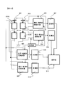
- FIG. 14 is a block diagram showing an example of a drive system of a vehicular rotating electrical machine to which the battery management system according to the present embodiment is applied.
- the drive system shown in FIG. 14 includes a battery module 9, a battery monitoring device 100 that monitors the battery module 9, an inverter device 220 that converts DC power from the battery module 9 into three-phase AC power, and a motor 230 for driving the vehicle. ing.
- the battery management system of this embodiment is adopted for the battery monitoring device 100.
- the motor 230 is driven by the three-phase AC power from the inverter device 220.
- the inverter device 220 and the battery monitoring device 100 are connected by CAN communication, and the inverter device 220 functions as a host controller for the battery monitoring device 100. Further, the inverter device 220 operates based on command information from a host controller (not shown).
- the inverter device 220 includes a power module 226, an MCU 222, and a driver circuit 224 for driving the power module 226.
- the power module 226 converts the DC power supplied from the battery module 9 into three-phase AC power for driving the motor 230.
- Inverter device 220 controls the phase of AC power generated by power module 226 with respect to the rotor of motor 230, and causes motor 230 to operate as a generator during vehicle braking.
- the three-phase AC power generated by the motor 230 is converted into DC power by the power module 226 and supplied to the battery module 9. As a result, the battery module 9 is charged.
- the battery module 9 is composed of two battery blocks 9A and 9B connected in series. Each battery block 9A, 9B is provided with 16 battery cells connected in series.
- the battery block 9A and the battery block 9B are connected in series via a maintenance / inspection service disconnect SD in which a switch and a fuse are connected in series. By opening this service disconnect SD, the direct circuit of the electric circuit is cut off, and even if a connection circuit is formed at one place between the battery blocks 9A and 9B and the vehicle, no current flows. With such a configuration, high safety can be maintained.
- a battery disconnect unit BDU including a relay RL, a resistor RP, and a precharge relay RLP is provided in the high-voltage line HV + between the battery module 9 and the inverter device 220.
- a series circuit of the resistor RP and the precharge relay RLP is connected in parallel with the relay RL.
- the battery monitoring device 100 mainly performs measurement of each cell voltage, measurement of total voltage, measurement of current, cell temperature, cell capacity adjustment, and the like.
- IC1 to IC6 as cell controllers are provided.
- the 16 battery cells provided in each battery block 9A, 9B are each divided into three cell groups, and one IC is provided for each cell group.
- IC1 to IC6 communicate with the microcomputer 30 in a daisy chain manner via an insulating element (for example, a photocoupler) PH, a communication system 602 for reading a cell voltage value and transmitting various commands, and only cell overcharge detection information. And a communication system 604 for transmitting.
- the communication system 602 is divided into an upper communication path for IC1 to IC3 of the battery block 9A and a lower communication path for IC4 to IC6 of the battery block 9B.
- a current sensor Si such as a Hall element is installed in the battery disconnect unit BDU, and the output of the current sensor Si is input to the microcomputer 30.
- Signals related to the total voltage and temperature of the battery module 9 are also input to the microcomputer 30 and measured by an AD converter (ADC) of the microcomputer 30.
- Temperature sensors are provided at a plurality of locations in the battery blocks 9A and 9B.
- FIG. 2 is a flowchart for explaining processing in the battery management system shown in FIG.
- the processing of the flowchart shown in FIG. 2 is executed when a device (electric vehicle, notebook PC, power system, etc.) provided with a battery management system starts to operate, at regular time intervals or at predetermined conditions until the device stops. Every time it is established, it is repeated periodically.
- the execution cycle is set to a predetermined value (for example, 100 ms).
- Step S20 the charge / discharge current value of the battery B is measured by the ammeter 10 of FIG.
- Step S21 a charge (current integration) is calculated based on the current value measured in step S20. That is, the charge (Ah) is calculated by (current value) ⁇ (time), and the time here is an elapsed time from the previous current measurement to the current current measurement, and the execution cycle described above is used. Note that the initial charge value at the start of operation (charge / discharge start) is set to zero.
- the charge calculation process in step S21 corresponds to the current integration unit 11 in FIG.
- Step S22 it is determined whether or not the charging rate calculation condition is met based on the current change rate, that is, whether or not the charging rate is calculated at the current measurement timing (program processing timing in FIG. 2).
- FIG. 3 is a diagram illustrating determination of the charging rate calculation condition in step S22
- FIG. 5 is a flowchart illustrating an example of detailed processing in step S22.
- the process of step S22 corresponds to the process of the measurement timing designation
- the battery state (charge rate (SOC: State of Charge), degree of deterioration, full charge capacity) is calculated based on the current value and the terminal voltage measured during operation (charging / discharging). I have to.
- the current value changes according to the state of the load (for example, a motor). Then, as shown in FIG. 3, if the battery state is calculated using the current value and the voltage value measured immediately after the current value suddenly changes, the calculation error increases.
- FIG. 3 is a diagram schematically showing a relationship between a change in current value and an error in the calculated charging rate.
- the current value changes by ⁇ I at time ta is shown.
- the calculated charging rate error changes greatly immediately after the current value changes, and thereafter, the error decreases after a certain amount of time has elapsed.
- the elapsed time after the current value changes is 2 seconds or more, the error is sufficiently small.
- the current value and the voltage value measured until a predetermined elapsed time elapses from the change of the current value are not used for calculation of the battery state (charging rate, deterioration degree, full charge capacity).
- the predetermined elapsed time ⁇ is referred to as a waiting time ⁇ .
- step S22 of FIG. 2 whether or not a current change greater than or equal to a predetermined value has occurred at the current process timing, or during a waiting time when there is a current change greater than or equal to a predetermined value It is determined whether or not. If a current change occurs or during a waiting time, it is determined that the condition is not satisfied, and the program of FIG. 2 is terminated. On the other hand, if it is determined that it is not during the waiting time, the process proceeds from step S22 to step S23.
- the current change is a current change per second
- a determination value for determining the current change is, for example, a current change per second that is a constant multiple C (the initial full charge capacity of the battery B).
- C discharge rate
- 0.1 C is 0.5 A, and therefore, a current change of 0.5 A or more occurs per second.
- 0.1C is an example, and it may be 0.3C larger than 0.1C.
- an optimal value may be set by testing with an actual machine in advance.
- the waiting time ⁇ may be a predetermined value (for example, 2 seconds described above), or may be the shortest time among the polarization time constants of the battery.
- the number of measurement data to be used for battery state calculation is reduced, and it is difficult to obtain the calculation timing. Therefore, in order to achieve both calculation frequency and error reduction, it is preferable that ⁇ be in the order of seconds both when a constant value is used and when the polarization time constant of the battery is used.
- FIG. 4 is a diagram showing an example of a circuit model of a battery, which is an ideal battery 31 (voltage after several hours since charging / discharging of the battery is stopped), DC resistance 32, polarization 1 (33), polarization 2 (34), It consists of + pole 35.
- polarization is expressed as a parallel connection of a resistor and a capacitor.
- ⁇ 1 is a time constant of about several seconds depending on the battery
- ⁇ 2 is a time constant of several minutes to several hours.
- ⁇ 1 is used as the waiting time ⁇ described above. 4 may be measured using a known electrochemical impedance (EIS) measurement method (AC impedance method) (Masayuki Itagaki: electrochemical impedance method principle, measurement / analysis, Maruzen).
- EIS electrochemical impedance
- AC impedance method electrochemical impedance method principle, measurement / analysis, Maruzen.
- ⁇ calculated by the following equation (1) may be used as the above-described waiting time ⁇ .
- the voltage per SOC 1% will be described in step S24 described later.
- the SOC error is a predetermined value (for example, 5%).
- ⁇ ⁇ 1 ⁇ ⁇ I ⁇ R1 / v
- v SOC 1% voltage
- the count number N is an index indicating the elapsed time since the current value has changed by a predetermined value or more, and the elapsed time is represented by N ⁇ execution cycle (for example, 100 ms).
- the count number N is stored in a memory provided in the controller, and the value of N at the start of operation is 0.
- M is an integer that satisfies the equation “M ⁇ execution cycle ⁇ ⁇ > (M ⁇ 1) ⁇ execution cycle”.
- FIG. 6 is a diagram showing changes in current, and t0 to t10 indicate processing timings when the program shown in FIG. 2 is executed.
- the current value changes by ⁇ I1 between time t0 and time t1, changes by ⁇ I2 between time t5 and time t6, and changes by ⁇ I3 between time t6 and time t7.
- any change amount ⁇ I1 to I3 is considered to be larger than the predetermined value when converted into a current change for one second.
- the program processing timing at time t9 and time t10 is the same as that at time t4 described above. Therefore, when the elapsed time from the current change between time t6 and time t7 becomes equal to or longer than the waiting time ⁇ , calculation of the battery state such as the charging rate is started again. By performing the process as shown in FIG. 5, when there is a current change of a predetermined value or more, the battery state is calculated after a predetermined waiting time has elapsed. Can be suppressed and the calculation accuracy can be improved.
- step S23 corresponds to the process of the voltage correction part 13 in the functional block diagram of FIG.
- the current and voltage are measured by the ammeter 10 and the voltage detection unit 11, and based on the measured current value and voltage value, the battery is left for several hours in a state where there is no charge / discharge of the battery.
- the battery terminal voltage is estimated using equation (2).
- Open-circuit voltage V + I ⁇ R-Vf (2)
- V, I, R, and Vf are as follows.
- I Measured current (positive for discharging and negative for charging)
- R DC resistance of the battery (resistance after the measurement cycle when the current changes)
- Vf battery polarization voltage
- V and I in the equation (2) are known because they are measured, but the DC resistance R and the polarization voltage Vf are unknown, and thus need to be estimated.
- the formula (3) may be used, or a table (index is set to SOC (charge rate) or SOH (degradation degree: State of Health), temperature) is set in advance). You may make it refer to a value.
- a thermometer for measuring the battery temperature is provided, and the measured temperature is used when referring to the table.
- R ⁇ V / ⁇ I (3)
- ⁇ V current battery voltage ⁇ 1battery voltage before measurement cycle
- ⁇ I current current ⁇ 1current before measurement cycle
- the resistance is not always required, and the current change ⁇ I is required to be large to some extent (for example, a change of 0.1 C or more). Therefore, when the current change ⁇ I is small and the value of the DC resistance R cannot always be prepared, the resistance value obtained when the previous current change occurs is avoided by using it.
- a method using a table a method described in “JP 2000-258513 A” may be used.
- the polarization voltage Vf may be obtained based on the past voltage and current by using the method described in “Japanese Unexamined Patent Application Publication No. 2007-171045”.
- step S24 the charging rate (SOC) is estimated from the open circuit voltage of the battery. Note that the process of step S24 corresponds to the process of the SOC estimation map 16 in the functional block diagram of FIG.
- FIG. 7 shows an example of an open-circuit voltage-charge rate (SOC) map.
- the map shown in FIG. 7 shows a case where the relationship between the open circuit voltage and the SOC does not change depending on the battery temperature, and is composed of a data group in which 0% to 100% of the SOC is divided in 10% increments.
- FIG. 8 is a graph showing the map of FIG.
- the data closest to 3.71 V is searched from the open voltage data group in the column shown on the left side of FIG. Here, it becomes 3.8V in the seventh stage.
- the sixth-stage data which is voltage data one rank lower than 3.8V is selected.
- a value may be obtained by linear interpolation from these two points (data).
- linear interpolation is used here, data estimation by well-known spline interpolation may be used using four points including 3.55 V data and 3.9 V data.
- a method of spline interpolation for example, the method described in “Yoshimoto Safuji-shi: Spline function and its application (mathematics of new application series 20), Education Publishing ⁇ (1979/01)” is used.
- FIG. 8 shows the characteristics of the ideal battery 31.
- the width of SOC1% when SOC is 80% is 79.5% to 80.5%.
- the difference between the open circuit voltage at 80.5% and the open circuit voltage at 79.5% is ⁇ V.
- This open-circuit voltage difference ⁇ V is defined as a voltage per 1% SOC.
- an example in which the SOC is 80% is shown, but the same calculation is performed for other SOCs (for example, 40%).
- step S25 a data pair (charge, SOC) stored in the SOC / charge storage unit 14 is added.
- the process of step S25 corresponds to the process of the SOC / charge storage unit 14 in the functional block diagram of FIG.
- As a method of adding a data pair it may be recorded every time a data pair is acquired, but may be recorded when there is a change of 1% or more from the previously recorded SOC without recording each time. .
- the data stored in the SOC / charge storage unit 14 is appropriately deleted. Also good.
- data deletion for example, data that has been accumulated for a certain period of time after accumulation is used. The fixed time T is determined by the charge error caused by the ammeter error.
- the error of the ammeter 10 is divided into an offset error and white noise, and the respective values are defined as Io [A] and Iw [A] (see the catalog value of the ammeter, or Determined by actual measurement). Then, if the error of the full charge capacity given in advance is Qe [Ah], T [h] satisfying the following equation (5) is set as the above-mentioned fixed time T.
- the error Qe is determined as Qmax ⁇ ⁇ using the error rate ⁇ of the full charge capacity Qmax.
- the value of the error rate ⁇ may be 5%, for example.
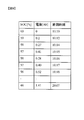
- FIG. 9 is a diagram showing a table in the SOC / charge storage unit 14, and an example of processing of the SOC / charge storage unit 14 will be described with reference to FIG.
- a data pair consisting of SOC and electric charge is stored together with the measurement time.
- the charge is an integral value from the initial value, the unit is Ah, and the discharge side is positive.
- the data at the measurement time 10:10 is the initial value
- the initial value of the SOC is 60%
- the initial value of the charge is 0%.
- FIG. 9 shows a case where the relationship between the SOC and the open circuit voltage does not change depending on the temperature.
- a table as shown in FIG. 9 is prepared for each temperature, and the table is selected according to the value of a thermometer separately attached to the battery. .
- the data at the measurement time is used when deleting the above-mentioned old data to prevent error deterioration or to prevent the memory from overflowing.
- step S26 it is determined whether to update the full charge capacity. If the update condition is satisfied, the process proceeds to step S27. If the update condition is not satisfied, the process proceeds to step S28. Note that the process of step S26 corresponds to the process of the update command unit 17 in the functional block diagram of FIG.
- step S26 the difference between the SOC minimum value and the maximum value in the data group stored in the table of FIG. 9 is taken, and the battery is fully charged when the difference is equal to or greater than a predetermined value.
- Update the capacity Even if it is updated once, if this update condition is satisfied, the update is performed after the next data addition.
- this predetermined value for example, a fixed value such as 20% or 15% is used.
- step S27 the full charge capacity of the battery is estimated based on the pair data of SOC and charge.
- the process of step S27 corresponds to the full charge capacity calculation part 18 in the functional block diagram of FIG.
- SOC is x
- charge is y
- the slope of a straight line indicating the relationship between x and y is obtained as the full charge capacity.
- the target data pair is all data stored in the SOC / charge storage unit 14.
- Charge full charge capacity x SOC + constant (6)
- the least square method is used.
- the method described in the reference “The University of Tokyo Faculty of Liberal Arts, Statistics Department: Introduction to Statistics, University of Tokyo Press, September 25, 2001, 20th edition” may be used.
- the reason for using the inclination is that, for example, when the SOC estimation shift occurs, the approximate straight line may move up and down on the coordinates, but the inclination is not affected, so that it is resistant to bias error deviation in the SOC estimation. It is.
- FIG. 10 is a plot of the data of FIG. 9 on coordinates where the horizontal axis is charge [Ah] and the horizontal axis is SOC [%].
- the data in the fifth row in FIG. 9 is the point D1 in FIG. 10, and for the plotted data group, the approximate straight line obtained by the least square is L1.
- the slope of this straight line L1 represents the full charge capacity.
- the slope is 0.1 Ah / SOC%, and the full charge capacity is calculated as 10 Ah, which is 100 times.
- SOH degree of deterioration
- step S28 display update processing of the display unit 19 is performed.
- FIG. 11 shows a display example of the display screen of the display unit 19. In the example shown in FIG. 11, the SOC, SOH, and remaining operation time are displayed. In FIG. 11, 81 indicates SOC, 82 indicates full charge capacity, 83 indicates SOH, and 84 indicates remaining usage time.
- SOC not only the percentage display by numerical value but also the SOC display with the bar display 86 of the battery display 85 for easy visual understanding. Therefore, the amount that can be used is indicated by the size of the portion denoted by reference numeral 86. Similarly, SOH is displayed on the bar display 87 of the battery display 88 as well as the percentage display by numerical values.
- the display on the display unit 19 is updated every time the charging rate is calculated. However, when the process proceeds from step S22 to step S28, the full charge capacity has not been calculated, so the SOH at the current processing timing is not calculated. The value of the full charge capacity has not yet been determined. In that case, the display color may be changed to display the final value when the previous operation was performed. Alternatively, instead of changing the display color, a blinking display may be used. The user can recognize from the display color that the SOH and the full charge capacity are not the latest.
- “100 ⁇ (current charge ⁇ charge of latest data stored in the SOC charge storage unit) / (full charge capacity)” is added to the latest SOC value measured by the SOC estimation map 16 of FIG. It may be an added value.
- the remaining usage time may be calculated by the following equation (7).
- the average current may be the average value of currents for the last 30 minutes (or 30 minutes instead of 30 minutes).
- Remaining usage time (current SOC-minimum SOC) x full charge capacity / average current x 100 ... (7)
- FIG. 12 shows an example in which a total of four 2 series batteries are connected in parallel. That is, the batteries 911A and 911B connected in series and the batteries 912A and 912B connected in series are connected in parallel. Ammeters 901 and 902 are provided at the places connected in series. For each of the batteries 911A, 911B, 912A, and 912B, measurement units 903, 904, 905, and 906 that can periodically measure current and voltage simultaneously are provided.
- the measurement start of the AD (Analog-to-Digital) circuit of a current sensor and a voltage sensor is performed synchronously between the measurement unit 903 and the measurement unit 904 provided in the batteries 912A and 912B connected in series.
- the measurement start of the AD circuit of the current sensor and the voltage sensor is performed in synchronization. Therefore, a synchronization signal is input from the synchronization unit 920 to each measurement unit 903, 904, 905, 906.
- calculation units 907 to 910 that perform the processing shown in FIG. 2 are provided for the measurement units 903 to 906, respectively.
- the display unit 913 performs display as shown in FIG. 13 based on the calculation results of the calculation units 907 to 910.
- the full charge capacity and SOC for each of the batteries 911A, 911B, 912A, and 912B are calculated by calculation units 907 to 910 shown in FIG.
- the capacity and remaining operation time of the entire battery are calculated by the following equations (8) and (9).
- the average current is, for example, the average value of currents for the last 30 minutes (or 30 minutes instead of 30 minutes).
- FIG. 13 is a diagram showing a display example.
- the display unit 913 includes a deterioration state screen 101 that collectively displays the deterioration state of each battery, a charge rate display screen 102 that collectively displays the charge rate state of each battery, and a battery group.
- the remaining usage time display 103 displays the total remaining usage time, and a display screen 104 displays which battery is deteriorated.
- Degradation state screen 101 shows the SOH of batteries 911A, 911B, 912A, and 912B connected in two series and two in parallel (degree of degradation: 100% ratio of [full charge capacity] / [full charge capacity of new battery] here) Display each.
- the SOH display corresponding to the battery 911 ⁇ / b> A of FIG. 12 is the display 105 ⁇ / b> A, and the SOH is displayed by the bar display 107 and the numerical display “SOH 70%” is displayed in an overlapping manner.
- the displays 105B, 106A, and 106B are SOH displays corresponding to the batteries 911B, 912A, and 912B, respectively.
- the charging rate display screen 102 has the same configuration as the deterioration state screen 101, and the displays 108A, 108B, 109A, and 109B are charging rate displays corresponding to the batteries 911B, 912A, and 912B, respectively.
- the charging rate is indicated by the bar display 110 and the numerical value display “SOC 70%” is displayed in an overlapping manner.
- the display screen 104 displaying the deteriorated battery displays a battery number whose SOH value is equal to or less than a predetermined threshold value.
- a predetermined threshold value for example, a fixed value of 50% may be used. If there is a battery for which the value of the full charge capacity has not been determined, the SOH value of the corresponding battery on the deterioration state screen 101 in FIG.
- the value of the usage time display 103 is tentatively calculated using the full charge capacity at the previous operation and is displayed in gray. After the value is confirmed, the value is displayed in black.
- the battery current value and the terminal voltage value at the time of charging and discharging the battery are measured, and the charging rate and the deterioration degree as the battery state are measured based on the measured current value and the terminal voltage value.
- the current value and terminal voltage value measured during the period until the battery is not used, and the battery charge rate, deterioration degree, and fullness are measured based on the current value and terminal voltage value measured during the battery charge / discharge period other than the above period. At least one of the charge capacities was calculated.
- the battery state is calculated using the current value and the terminal voltage detected during charging / discharging, even when there is no clear battery suspension state in the power system or electric vehicle, The battery state can be estimated.
- the current value and the terminal voltage value immediately after a current change of a predetermined value or more are transient values, calculating the battery state using them results in a value with a large error and lacking reliability.
- the current change per second is greater than or equal to a predetermined value, a transient period until a predetermined time elapses. Since the detected current value and terminal voltage value are not used, the battery state can be calculated with higher accuracy. Note that the same processing as when there is a change in current of a predetermined value or more may be performed at the beginning of current flow at the start of operation.
- an ammeter 10 that detects the current value of the battery B
- a voltage detection unit 12 that detects a terminal voltage value of the battery B
- a current value detected by the ammeter 10 per second As a configuration of the battery management system, an ammeter 10 that detects the current value of the battery B, a voltage detection unit 12 that detects a terminal voltage value of the battery B, and a current value detected by the ammeter 10 per second.
- a measurement timing designating unit 15 that detects a current change whose change is equal to or greater than a predetermined value, and a current value and a terminal voltage value detected during a period from when the current change is detected by the measurement timing designating unit 15 until a predetermined time elapses.
- a battery state calculation unit that calculates at least one of a charging rate, a degree of deterioration, and a full charge capacity as a battery state based on a current value and a terminal voltage value that are not used and are detected in a battery charge / discharge period other than that period (For example, a full charge capacity calculation unit 18 for calculating a full charge capacity).
- measuring units 903 and 904 that can periodically measure current and voltage for each battery 911A, 911B, 912A, and 912B at the same time.
- 905, 906 are provided.
- a battery state should just be calculated about each of a some battery. As a result, the battery state of each battery can be calculated with high accuracy.
- the display units 19 and 913 which are display devices that display the battery state calculated by the battery state calculation unit, the user can easily recognize the battery state.
- the full charge capacity if the full charge capacity corresponding to the charging rate is not calculated, the most recently calculated full charge capacity and the degree of deterioration of the battery based on the full charge capacity are displayed. . By doing so, the full charge capacity and the degree of deterioration are always displayed in the same manner as the charge rate, and the user can know the outline of the battery state even when the full charge capacity is not calculated.
- the full charge capacity corresponding to the charge rate is displayed as a display form of the full charge capacity and the degree of deterioration.
- the full charge capacity and the deterioration degree are not the current values but the latest values.
- the battery B represents a management unit.
- each of a plurality of battery cells included in the battery module 9 of FIG. 14 may be the battery B, and each cell group may be the battery B.
- each of the battery blocks 9A and 9B may be a battery B, and of course, the battery module 9 may be a battery B.
- all the battery cells are connected in series, but a configuration including series connection and parallel connection may be used.
- all the battery cells included in the battery module 9 may be displayed, but for each battery replacement unit, for example, for each of the battery blocks 9A and 9B in FIG. It is realistic and preferable to display the average value.
Abstract
Description
本発明の第2の態様によると、電池管理システムは、電池の電流値を検出する電流検出部と、電池の端子電圧値を検出する電圧検出部と、電流検出部で検出された電流値の1秒当たりの変化が所定値以上である電流変化を検出する電流変化検出部と、電流変化検出部による電流変化の検出時から所定時間が経過するまでの期間に検出された電流値および端子電圧値は使用せず、期間以外の電池充放電期間において検出された電流値および端子電圧値に基づいて、電池状態としての充電率、劣化度および満充電容量の少なくとも一つを算出する電池状態算出部と、を備える。
本発明の第3の態様によると、第2の態様の電池管理システムにおいて、所定時間に、電池の分極時定数の内の最も小さな分極時定数、または、2秒を用いるのが好ましい。
本発明の第4の態様によると、第2または3の態様の電池管理システムにおいて、放電率で0.1Cに相当する電流値を、前記1秒当たりの電流値の変化として用いるのが好ましい。
本発明の第5の態様によると、第2乃至4のいずれか一の態様の電池管理システムにおいて、電池状態算出部で算出された電池状態を表示する表示装置を備えたものである。
本発明の第6の態様によると、第2乃至4のいずれか一の態様の電池管理システムにおいて、電池状態算出部で算出された充電率の内、現時点から過去に遡った所定数以内の充電率が蓄積される蓄積部を備え、電池状態算出部による満充電容量の算出が、蓄積部に蓄積されている充電率の最大値と最小値との差が所定充電率差以上の場合に行われるようにしたものである。
本発明の第7の態様によると、第6の態様の電池管理システムにおいて、所定充電率差を15%としたものである。
本発明の第8の態様によると、第6または7の態様の電池管理システムにおいて、電池状態算出部で算出された電池状態を表示する表示装置を備え、表示装置は、電池状態算出部により充電率が算出されると、充電率の表示を算出された充電率で更新し、充電率に対応した満充電容量の算出が行われていない場合には、直近に算出された満充電容量および該満充電容量に基づく電池の劣化度を表示するようにしたものである。
本発明の第9の態様によると、第8の態様の電池管理システムにおいて、直近に算出された満充電容量および該満充電容量に基づく電池の劣化度を表示する場合には、満充電容量および劣化度の表示形態を、充電率に対応した満充電容量を表示する場合の表示形態と異ならせるのが好ましい。
本発明の第10の態様によると、第2の態様の電池管理システムにおいて、電池は複数の電池セルから成り、電池状態検出部は、電池の充電率、劣化度および満充電容量の少なくとも一つを前記複数の電池セルの各々について算出するものである。
本発明の第11の態様によると、第2の態様の電池管理システムにおいて、電池は、複数の電池セルから成る電池ブロックを複数備え、電池状態検出部は、電池の充電率、劣化度および満充電容量の少なくとも一つを複数の電池ブロックの各々について算出するものである。
本発明の第12の態様によると、第10または11の態様の電池管理システムにおいて、複数の電池の接続に少なくとも直列接続が含まれ、電流値および端子電圧値の検出が直列接続された複数の電池の間で同時期に行われるように、電流検出部による検出および電圧検出部による各電池の検出をそれぞれ同期させる同期装置を備えるようにしたものである。
本発明の第13の態様によると、第11の態様の電池管理システムにおいて、電池状態算出部で算出された電池状態を表示する表示装置を備え、表示装置は、電池状態算出部で算出された電池状態を前記複数の電池ブロック毎に表示するものである。 According to the first aspect of the present invention, the battery state estimation method measures the current value and the terminal voltage value of the battery at the time of charging and discharging the battery, and based on the measured current value and the terminal voltage value, A battery state estimation method for calculating at least one of a charging rate, a degree of deterioration, and a full charge capacity, and when a change in measured current value per second is a predetermined value or more, occurrence of a current change The battery charging rate based on the current value and the terminal voltage value measured in the battery charging / discharging period other than the above period is not used. And calculating at least one of the deterioration degree and the full charge capacity.
According to the second aspect of the present invention, the battery management system includes a current detection unit that detects a current value of the battery, a voltage detection unit that detects a terminal voltage value of the battery, and a current value detected by the current detection unit. A current change detection unit that detects a current change whose change per second is equal to or greater than a predetermined value, and a current value and a terminal voltage detected in a period from when the current change is detected by the current change detection unit until a predetermined time elapses. Battery state calculation that calculates at least one of the charging rate, the degree of deterioration, and the full charge capacity as the battery state based on the current value and the terminal voltage value detected in the battery charging / discharging period other than the period without using the value A section.
According to the third aspect of the present invention, in the battery management system of the second aspect, it is preferable to use the smallest polarization time constant of the battery polarization time constant or 2 seconds for a predetermined time.
According to the fourth aspect of the present invention, in the battery management system of the second or third aspect, it is preferable to use a current value corresponding to a discharge rate of 0.1 C as the change in the current value per second.
According to a fifth aspect of the present invention, the battery management system according to any one of the second to fourth aspects includes a display device that displays the battery state calculated by the battery state calculation unit.
According to the sixth aspect of the present invention, in the battery management system according to any one of the second to fourth aspects, the charging is performed within a predetermined number from the present time to the past among the charge rates calculated by the battery state calculation unit. The battery state calculation unit calculates the full charge capacity when the difference between the maximum value and the minimum value of the charge rate stored in the storage unit is equal to or greater than the predetermined charge rate difference. It is intended to be.
According to a seventh aspect of the present invention, in the battery management system of the sixth aspect, the predetermined charging rate difference is 15%.
According to an eighth aspect of the present invention, in the battery management system according to the sixth or seventh aspect, the battery management system includes a display device that displays the battery state calculated by the battery state calculation unit, and the display device is charged by the battery state calculation unit. When the rate is calculated, the display of the charge rate is updated with the calculated charge rate, and when the full charge capacity corresponding to the charge rate has not been calculated, the most recently calculated full charge capacity and the The battery deterioration level based on the full charge capacity is displayed.
According to the ninth aspect of the present invention, in the battery management system of the eighth aspect, when displaying the most recently calculated full charge capacity and the degree of deterioration of the battery based on the full charge capacity, the full charge capacity and It is preferable to make the display form of the deterioration degree different from the display form in the case of displaying the full charge capacity corresponding to the charging rate.
According to a tenth aspect of the present invention, in the battery management system according to the second aspect, the battery is composed of a plurality of battery cells, and the battery state detection unit is at least one of a battery charge rate, a degree of deterioration, and a full charge capacity. Is calculated for each of the plurality of battery cells.
According to an eleventh aspect of the present invention, in the battery management system according to the second aspect, the battery includes a plurality of battery blocks each including a plurality of battery cells, and the battery state detection unit includes the battery charge rate, the degree of deterioration, and the fullness. At least one of the charging capacities is calculated for each of the plurality of battery blocks.
According to a twelfth aspect of the present invention, in the battery management system according to the tenth or eleventh aspect, the connection of the plurality of batteries includes at least a series connection, and the detection of the current value and the terminal voltage value is performed in series. A synchronization device that synchronizes the detection by the current detection unit and the detection of each battery by the voltage detection unit is provided so as to be performed at the same time between the batteries.
According to a thirteenth aspect of the present invention, the battery management system according to the eleventh aspect includes a display device that displays the battery state calculated by the battery state calculation unit, and the display device is calculated by the battery state calculation unit. A battery state is displayed for each of the plurality of battery blocks.
機器システム側に設けられたコントローラ、例えば、ノートPC、電気自動車内のコントローラ、電力系統コントローラ内のソフトウエアで実現される。例えば、電気自動車であれば、電池制御用に設けられたバッテリコントローラのソフトウェアによって実現される。もちろん、電池管理システム専用のコントローラを備えて、それに実行させるようにしてもかまわない。 In the configuration shown in FIG. 1, the
It is realized by a controller provided on the device system side, for example, a notebook PC, a controller in an electric vehicle, or software in a power system controller. For example, in the case of an electric vehicle, it is realized by software of a battery controller provided for battery control. Of course, a controller dedicated to the battery management system may be provided and executed.
ステップS20では、図1の電流計10により電池Bの充放電電流値を計測する。 (Step S20)
In step S20, the charge / discharge current value of the battery B is measured by the
ステップS21では、ステップS20で計測した電流値に基づいて電荷(電流積分)を計算する。すなわち、電荷(Ah)は(電流値)×(時間)で計算され、ここでの時間は前回電流計測から今回電流計測までの経過時間であって、上述した実行周期が用いられる。なお、稼働開始(充放電開始)時の電荷の初期値は0としておく。このステップS21の電荷計算処理は、図1の電流積分部11に該当する。 (Step S21)
In step S21, a charge (current integration) is calculated based on the current value measured in step S20. That is, the charge (Ah) is calculated by (current value) × (time), and the time here is an elapsed time from the previous current measurement to the current current measurement, and the execution cycle described above is used. Note that the initial charge value at the start of operation (charge / discharge start) is set to zero. The charge calculation process in step S21 corresponds to the
ステップS22では、電流の変化率に基づいて充電率計算条件に合致するかどうか、すなわち、今回の計測タイミング(図2のプログラム処理タイミング)において充電率計算を行うか否かを判定する。図3は、ステップS22における充電率計算条件の判定を説明する図であり、図5はステップS22の詳細処理の一例を示すフローチャートである。なお、ステップS22の処理は、図1の計測タイミング指定部15の処理に該当する。 (Step S22)
In step S22, it is determined whether or not the charging rate calculation condition is met based on the current change rate, that is, whether or not the charging rate is calculated at the current measurement timing (program processing timing in FIG. 2). FIG. 3 is a diagram illustrating determination of the charging rate calculation condition in step S22, and FIG. 5 is a flowchart illustrating an example of detailed processing in step S22. In addition, the process of step S22 corresponds to the process of the measurement timing designation | designated
τ=τ1×ΔI×R1/v …(1)
v=SOC1%の電圧×SOC誤差
τ1:分極時定数の中でも最も短い時間
ΔI:電流差(1周期前の計測電流―今回の電流)
R1:図4中のR1 Further, instead of the time constant of polarization, τ calculated by the following equation (1) may be used as the above-described waiting time τ. The voltage per
τ = τ1 × ΔI × R1 / v (1)
v =
R1: R1 in FIG.
次に、ステップS23の処理について説明する。なお、ステップS23の処理は、図1の機能ブロック図では電圧補正部13の処理に該当する。ステップS23では、電流計10および電圧検出部11により電流および電圧を計測し、計測された電流値および電圧値に基づいて、開放電圧、すなわち電池の充放電が無い状態で数時間放置した後の電池端子電圧を式(2)を用いて推定する。
開放電圧=V+I・R-Vf …(2)
なお、式(2)において、V,I,R,Vfは以下の通りである。
V:測定した電池の電圧
I:測定した電流(放電の場合をプラス、充電の場合をマイナスとする)
R:電池の直流抵抗(電流が変化して、計測周期後の抵抗)
Vf:電池の分極電圧 (Description of step S23)
Next, the process of step S23 will be described. In addition, the process of step S23 corresponds to the process of the
Open-circuit voltage = V + I · R-Vf (2)
In the formula (2), V, I, R, and Vf are as follows.
V: Measured battery voltage I: Measured current (positive for discharging and negative for charging)
R: DC resistance of the battery (resistance after the measurement cycle when the current changes)
Vf: battery polarization voltage
R=ΔV/ΔI …(3)
ΔV=現在の電池電圧-1計測周期前の電池電圧
ΔI=現在の電流-1計測周期前の電流 Here, V and I in the equation (2) are known because they are measured, but the DC resistance R and the polarization voltage Vf are unknown, and thus need to be estimated. As an estimation method of the DC resistance R, the formula (3) may be used, or a table (index is set to SOC (charge rate) or SOH (degradation degree: State of Health), temperature) is set in advance). You may make it refer to a value. When using a table, a thermometer for measuring the battery temperature is provided, and the measured temperature is used when referring to the table.
R = ΔV / ΔI (3)
ΔV = current battery voltage−1battery voltage before measurement cycle ΔI = current current−1current before measurement cycle
ステップS24では、電池の開放電圧から充電率(SOC)を推定する。なお、ステップS24の処理は、図1の機能ブロック図ではSOC推定マップ16の処理に該当する。本実施の形態における充電率(SOC)は式(4)により定義されるが、実際の推定方法としては、予め用意された充電率-開放電圧マップを用いる。
SOC=100×現在の充電量[Ah]/初期満充電容量[Ah] …(4) (Description of step S24)
In step S24, the charging rate (SOC) is estimated from the open circuit voltage of the battery. Note that the process of step S24 corresponds to the process of the
SOC = 100 × current charge amount [Ah] / initial full charge capacity [Ah] (4)
ステップS25では、SOC・電荷蓄積部14に蓄えられるデータペア(電荷,SOC)を追加する。なお、ステップS25の処理は、図1の機能ブロック図ではSOC・電荷蓄積部14の処理に該当する。データペアを追加の仕方としては、データペアを取得する度に毎回記録しても良いが、毎回記録せずに、前回記録したSOCから1%以上の変化があった場合に記録するとしても良い。 (Description of step S25)
In step S25, a data pair (charge, SOC) stored in the SOC /
Io×T+Iw×√T×ΔT=Qe …(5) Specifically, the error of the
Io × T + Iw × √T × ΔT = Qe (5)
ステップS26では、満充電容量の更新判断を行い、更新条件を満たす場合にはステップS27へ進み、更新条件を満たさない場合にはステップS28へ進む。なお、ステップS26の処理は、図1の機能ブロック図では更新指令部17の処理に該当する。 (Description of step S26)
In step S26, it is determined whether to update the full charge capacity. If the update condition is satisfied, the process proceeds to step S27. If the update condition is not satisfied, the process proceeds to step S28. Note that the process of step S26 corresponds to the process of the
ステップS27では、SOCと電荷とのペアデータに基づいて、電池の満充電容量を推定する。なお、ステップS27の処理は、図1の機能ブロック図では満充電容量計算部18に該当する。満充電容量の推定には次式(6)の関係を用い、SOCをx、電荷をyとし、x、yの関係を示す直線の傾きを満充電容量として求める。また、対象とするデータペアは、SOC・電荷蓄積部14に蓄積されている全データとする。
電荷=満充電容量×SOC+定数 …(6) (Description of step S27)
In step S27, the full charge capacity of the battery is estimated based on the pair data of SOC and charge. In addition, the process of step S27 corresponds to the full charge
Charge = full charge capacity x SOC + constant (6)
ステップS28では表示部19の表示更新処理を行う。図11は、表示部19の表示画面の表示例を示したものである。図11に示す例では、SOC、SOH、残稼働時間を表示するようにしている。図11において、81はSOCを示し、82は満充電容量を示し、83はSOHを示し、84は残使用時間を示している。 (Description of step S28)
In step S28, display update processing of the
残使用時間=(現在のSOC-最低SOC)×満充電容量/平均電流×100
…(7) As the SOC, “100 × (current charge−charge of latest data stored in the SOC charge storage unit) / (full charge capacity)” is added to the latest SOC value measured by the
Remaining usage time = (current SOC-minimum SOC) x full charge capacity / average
... (7)
容量[Ah]={電池911A満充電容量×電池911A充電率
+電池911B満充電容量×電池911B充電率
+電池912A満充電容量×電池912A充電率
+電池912B満充電容量×電池912B充電率}/100 …(8)
残稼働時間=容量/平均電流 …(9) Next, a method for calculating the remaining usage time in the entire battery group will be described. The full charge capacity and SOC for each of the
Capacity [Ah] = {
Remaining operation time = capacity / average current (9)
Claims (13)
- 電池充放電時の電池の電流値および端子電圧値を計測し、計測された電流値および端子電圧値に基づいて、電池状態としての充電率、劣化度および満充電容量の少なくとも一つを算出する電池状態推定方法であって、
前記計測された電流値の1秒当たりの変化が所定値以上であった場合には、前記電流変化の発生から所定時間が経過するまでの期間に計測された電流および端子電圧は使用せず、前記期間以外の電池充放電期間において計測された電流値値および端子電圧値に基づいて、前記電池の充電率、劣化度および満充電容量の少なくとも一つを算出する電池状態推定方法。 Measure the battery current value and terminal voltage value when charging and discharging the battery, and calculate at least one of the charging rate, deterioration degree, and full charge capacity as the battery state based on the measured current value and terminal voltage value A battery state estimation method comprising:
When the change per second of the measured current value is greater than or equal to a predetermined value, the current and terminal voltage measured during the period until the predetermined time elapses from the occurrence of the current change is not used, A battery state estimation method for calculating at least one of a charging rate, a deterioration degree, and a full charge capacity of the battery based on a current value value and a terminal voltage value measured in a battery charging / discharging period other than the period. - 電池の電流値を検出する電流検出部と、
電池の端子電圧値を検出する電圧検出部と、
前記電流検出部で検出された電流値の1秒当たりの変化が所定値以上である電流変化を検出する電流変化検出部と、
前記電流変化検出部による電流変化の検出時から所定時間が経過するまでの期間に検出された電流値および端子電圧値は使用せず、前記期間以外の電池充放電期間において検出された電流値および端子電圧値に基づいて、電池状態としての充電率、劣化度および満充電容量の少なくとも一つを算出する電池状態算出部と、を備える電池管理システム。 A current detector for detecting the current value of the battery;
A voltage detector for detecting the terminal voltage value of the battery;
A current change detection unit for detecting a current change in which a change per second in a current value detected by the current detection unit is equal to or greater than a predetermined value;
The current value and the terminal voltage value detected during a period from when the current change is detected by the current change detection unit until a predetermined time elapses are used, and the current value detected during the battery charge / discharge period other than the period and A battery management system comprising: a battery state calculation unit that calculates at least one of a charge rate, a deterioration degree, and a full charge capacity as a battery state based on a terminal voltage value. - 請求項2に記載の電池管理システムにおいて、
前記所定時間に、前記電池の分極時定数の内の最も小さな分極時定数、または、2秒を用いた電池管理システム。 The battery management system according to claim 2,
A battery management system that uses the smallest polarization time constant of the battery polarization time constant or 2 seconds for the predetermined time. - 請求項2または3に記載の電池管理システムにおいて、
放電率で0.1Cに相当する電流値を、前記1秒当たりの電流値の変化として用いた電池管理システム。 The battery management system according to claim 2 or 3,
A battery management system using a current value corresponding to 0.1 C in terms of discharge rate as a change in current value per second. - 請求項2乃至4のいずれか一項に記載の電池管理システムにおいて、
前記電池状態算出部で算出された前記電池状態を表示する表示装置を備えた電池管理システム。 In the battery management system according to any one of claims 2 to 4,
A battery management system comprising a display device that displays the battery state calculated by the battery state calculation unit. - 請求項2乃至4のいずれか一項に記載の電池管理システムにおいて、
前記電池状態算出部で算出された充電率の内、現時点から過去に遡った所定数以内の充電率が蓄積される蓄積部を備え、
前記電池状態算出部による前記満充電容量の算出が、前記蓄積部に蓄積されている充電率の最大値と最小値との差が所定充電率差以上の場合に行われる電池管理システム。 In the battery management system according to any one of claims 2 to 4,
Of the charging rate calculated by the battery state calculation unit, comprising a storage unit for storing a charging rate within a predetermined number retroactive from the present time,
The battery management system in which the calculation of the full charge capacity by the battery state calculation unit is performed when the difference between the maximum value and the minimum value of the charge rate stored in the storage unit is greater than or equal to a predetermined charge rate difference. - 請求項6に記載の電池管理システムにおいて、
前記所定充電率差を15%とした電池管理システム。 The battery management system according to claim 6, wherein
A battery management system in which the predetermined charging rate difference is 15%. - 請求項6または7に記載の電池管理システムにおいて、
前記電池状態算出部で算出された前記電池状態を表示する表示装置を備え、
前記表示装置は、
前記電池状態算出部により充電率が算出されると、充電率の表示を算出された充電率で更新し、
前記充電率に対応した前記満充電容量の算出が行われていない場合には、直近に算出された満充電容量および該満充電容量に基づく電池の劣化度を表示する電池管理システム。 The battery management system according to claim 6 or 7,
A display device that displays the battery state calculated by the battery state calculation unit;
The display device
When the charging rate is calculated by the battery state calculation unit, the display of the charging rate is updated with the calculated charging rate,
A battery management system that displays the most recently calculated full charge capacity and the degree of battery deterioration based on the full charge capacity when the full charge capacity corresponding to the charge rate is not calculated. - 請求項8に記載の電池管理システムにおいて、
前記直近に算出された満充電容量および該満充電容量に基づく電池の劣化度を表示する場合には、満充電容量および劣化度の表示形態を、前記充電率に対応した満充電容量を表示する場合の表示形態と異ならせた電池管理システム。 The battery management system according to claim 8, wherein
When displaying the most recently calculated full charge capacity and the degree of deterioration of the battery based on the full charge capacity, the full charge capacity and the degree of deterioration are displayed as the full charge capacity corresponding to the charge rate. Battery management system different from the display form of the case. - 請求項2に記載の電池管理システムにおいて、
前記電池は複数の電池セルから成り、
前記電池状態検出部は、電池の充電率、劣化度および満充電容量の少なくとも一つを前記複数の電池セルの各々について算出する電池管理システム。 The battery management system according to claim 2,
The battery is composed of a plurality of battery cells,
The battery state detection unit is a battery management system that calculates at least one of a battery charge rate, a deterioration degree, and a full charge capacity for each of the plurality of battery cells. - 請求項2に記載の電池管理システムにおいて、
前記電池は、複数の電池セルから成る電池ブロックを複数備え、
前記電池状態検出部は、電池の充電率、劣化度および満充電容量の少なくとも一つを前記複数の電池ブロックの各々について算出する電池管理システム。 The battery management system according to claim 2,
The battery includes a plurality of battery blocks including a plurality of battery cells,
The battery state detection unit is a battery management system that calculates at least one of a battery charge rate, a degree of deterioration, and a full charge capacity for each of the plurality of battery blocks. - 請求項10または11に記載の電池管理システムにおいて、
前記複数の電池の接続に少なくとも直列接続が含まれ、
前記電流値および端子電圧値の検出が前記直列接続された複数の電池の間で同時期に行われるように、前記電流検出部による検出および前記電圧検出部による各電池の検出をそれぞれ同期させる同期装置を備えた電池管理システム。 The battery management system according to claim 10 or 11,
The connection of the plurality of batteries includes at least a series connection,
Synchronizing the detection by the current detection unit and the detection of each battery by the voltage detection unit so that the detection of the current value and the terminal voltage value are performed simultaneously between the plurality of batteries connected in series. Battery management system with device. - 請求項11に記載の電池管理システムにおいて、
前記電池状態算出部で算出された前記電池状態を表示する表示装置を備え、
前記表示装置は、前記電池状態算出部で算出された前記電池状態を前記複数の電池ブロック毎に表示する電池管理システム。 The battery management system according to claim 11,
A display device that displays the battery state calculated by the battery state calculation unit;
The display device is a battery management system that displays the battery state calculated by the battery state calculation unit for each of the plurality of battery blocks.
Priority Applications (6)
| Application Number | Priority Date | Filing Date | Title |
|---|---|---|---|
| PCT/JP2011/055251 WO2012120620A1 (en) | 2011-03-07 | 2011-03-07 | Battery state estimating method and battery management system |
| US14/000,030 US20130320989A1 (en) | 2011-03-07 | 2011-03-07 | Battery state estimation method and battery control system |
| KR1020137019499A KR20130121143A (en) | 2011-03-07 | 2011-03-07 | Battery state estimating method and battery management system |
| JP2013503262A JPWO2012120620A1 (en) | 2011-03-07 | 2011-03-07 | Battery state estimation method and battery management system |
| EP11860301.8A EP2685269A4 (en) | 2011-03-07 | 2011-03-07 | Battery state estimating method and battery management system |
| CN2011800684392A CN103392133A (en) | 2011-03-07 | 2011-03-07 | Battery state estimating method and battery management system |
Applications Claiming Priority (1)
| Application Number | Priority Date | Filing Date | Title |
|---|---|---|---|
| PCT/JP2011/055251 WO2012120620A1 (en) | 2011-03-07 | 2011-03-07 | Battery state estimating method and battery management system |
Publications (1)
| Publication Number | Publication Date |
|---|---|
| WO2012120620A1 true WO2012120620A1 (en) | 2012-09-13 |
Family
ID=46797627
Family Applications (1)
| Application Number | Title | Priority Date | Filing Date |
|---|---|---|---|
| PCT/JP2011/055251 WO2012120620A1 (en) | 2011-03-07 | 2011-03-07 | Battery state estimating method and battery management system |
Country Status (6)
| Country | Link |
|---|---|
| US (1) | US20130320989A1 (en) |
| EP (1) | EP2685269A4 (en) |
| JP (1) | JPWO2012120620A1 (en) |
| KR (1) | KR20130121143A (en) |
| CN (1) | CN103392133A (en) |
| WO (1) | WO2012120620A1 (en) |
Cited By (15)
| Publication number | Priority date | Publication date | Assignee | Title |
|---|---|---|---|---|
| JP2014190727A (en) * | 2013-03-26 | 2014-10-06 | Nec Access Technica Ltd | Device and method for estimating remaining capacity of storage battery |
| TWI472784B (en) * | 2013-07-05 | 2015-02-11 | Lg Chemical Ltd | Method and system for calculating soc of battery |
| WO2014147475A3 (en) * | 2013-03-22 | 2015-02-26 | Toyota Jidosha Kabushiki Kaisha | Electrical storage system, and full charge capacity estimation method for electrical storage device |
| CN104737410A (en) * | 2013-09-27 | 2015-06-24 | 松下知识产权经营株式会社 | Power distribution device and storage battery pack diagnosing method |
| KR20150102016A (en) * | 2012-12-27 | 2015-09-04 | 로베르트 보쉬 게엠베하 | Method for determining a charge state |
| JP2016024170A (en) * | 2014-07-24 | 2016-02-08 | 日立オートモティブシステムズ株式会社 | Battery control device |
| EP2957921A4 (en) * | 2013-07-04 | 2016-03-09 | Lg Chemical Ltd | Method and system for estimating soc of battery |
| WO2018051442A1 (en) * | 2016-09-14 | 2018-03-22 | 株式会社東芝 | Electric storage capacity estimation device, method and program |
| JP2019509611A (en) * | 2015-12-30 | 2019-04-04 | ハイパードライブ イノベーション リミテッド | Battery management system |
| JP2019095861A (en) * | 2017-11-17 | 2019-06-20 | 株式会社東芝 | Neural network device |
| JP2021035126A (en) * | 2019-08-21 | 2021-03-01 | 東芝エネルギーシステムズ株式会社 | Battery capacity estimation device, battery capacity estimation method, and program |
| CN114035049A (en) * | 2021-11-08 | 2022-02-11 | 东软睿驰汽车技术(沈阳)有限公司 | SOH precision calculation method and device and electronic equipment |
| EP4059769A1 (en) * | 2021-03-18 | 2022-09-21 | Huawei Digital Power Technologies Co., Ltd. | Cloud-device synergy-based battery management system, vehicle, and battery management method |
| JP7388964B2 (en) | 2020-03-26 | 2023-11-29 | 株式会社日立製作所 | Secondary battery equipment and secondary battery system |
| US11961977B2 (en) | 2015-12-30 | 2024-04-16 | Turntide Drives Limited | Battery management system |
Families Citing this family (67)
| Publication number | Priority date | Publication date | Assignee | Title |
|---|---|---|---|---|
| US10924042B2 (en) * | 2009-09-23 | 2021-02-16 | The Boeing Company | Pneumatic energy harvesting and monitoring |
| DE102010001529A1 (en) * | 2010-02-03 | 2011-08-04 | SB LiMotive Company Ltd., Kyonggi | Adaptive method for determining the performance parameters of a battery |
| WO2012132459A1 (en) * | 2011-03-30 | 2012-10-04 | パナソニック株式会社 | Vehicle charging device |
| US9037426B2 (en) * | 2011-05-13 | 2015-05-19 | GM Global Technology Operations LLC | Systems and methods for determining cell capacity values in a multi-cell battery |
| JP2012247339A (en) * | 2011-05-30 | 2012-12-13 | Renesas Electronics Corp | Semiconductor integrated circuit and operation method therefor |
| DE102012204849A1 (en) * | 2012-03-27 | 2013-10-02 | Robert Bosch Gmbh | Method and control device for controlling a hybrid drive of a hybrid electric motor vehicle |
| US9318901B2 (en) | 2012-11-30 | 2016-04-19 | Tesla Motors, Inc. | Response to detection of an overdischarge event in a series connected battery element |
| US9343911B2 (en) | 2012-11-30 | 2016-05-17 | Tesla Motors, Inc. | Response to detection of an overcharge event in a series connected battery element |
| US9529048B2 (en) * | 2012-11-30 | 2016-12-27 | Tesla Motors, Inc. | Transient detection of an exceptional charge event in a series connected battery element |
| US9551758B2 (en) * | 2012-12-27 | 2017-01-24 | Duracell U.S. Operations, Inc. | Remote sensing of remaining battery capacity using on-battery circuitry |
| US9077181B2 (en) * | 2013-01-11 | 2015-07-07 | GM Global Technology Operations LLC | Battery section balancing methods and systems |
| US20140306712A1 (en) * | 2013-04-12 | 2014-10-16 | Broadcom Corporation | Tracking aging effect on battery impedance and tracking battery state of health |
| US9478850B2 (en) | 2013-05-23 | 2016-10-25 | Duracell U.S. Operations, Inc. | Omni-directional antenna for a cylindrical body |
| FR3006450B1 (en) * | 2013-06-04 | 2015-05-22 | Renault Sa | METHOD FOR ESTIMATING THE HEALTH STATUS OF AN ELECTROCHEMICAL CELL FOR STORING ELECTRIC ENERGY |
| US9726763B2 (en) | 2013-06-21 | 2017-08-08 | Duracell U.S. Operations, Inc. | Systems and methods for remotely determining a battery characteristic |
| KR101509001B1 (en) * | 2013-10-31 | 2015-04-07 | 현대모비스 주식회사 | Apparatus and Method Deciding Degradation of High Voltage Battery for Vehicle |
| JP6221728B2 (en) * | 2013-12-19 | 2017-11-01 | 日産自動車株式会社 | Degradation state detection device |
| KR102171096B1 (en) | 2014-04-21 | 2020-10-28 | 삼성전자주식회사 | Method and device to estimate battery lifetime during driving of electrical vehicle |
| US9882250B2 (en) | 2014-05-30 | 2018-01-30 | Duracell U.S. Operations, Inc. | Indicator circuit decoupled from a ground plane |
| US9535129B2 (en) * | 2014-06-17 | 2017-01-03 | GM Global Technology Operations LLC | Systems and methods for estimating battery pack capacity during charge sustaining use |
| CN104360285B (en) * | 2014-11-28 | 2017-03-01 | 山东鲁能智能技术有限公司 | A kind of battery capacity modification method based on improved ampere-hour integration method |
| JP6516091B2 (en) * | 2014-12-25 | 2019-05-22 | 三菱自動車工業株式会社 | Charge amount display device of electric vehicle |
| CN104569841A (en) * | 2014-12-26 | 2015-04-29 | 国家电网公司 | Aging detection method and device for battery pack |
| WO2016129212A1 (en) * | 2015-02-13 | 2016-08-18 | パナソニックIpマネジメント株式会社 | Cell status estimation device and power supply device |
| US10386418B2 (en) * | 2015-02-19 | 2019-08-20 | Mitsubishi Electric Corporation | Battery state estimation device |
| US11144106B2 (en) | 2015-04-13 | 2021-10-12 | Semiconductor Components Industries, Llc | Battery management system for gauging with low power |
| AU2016203834A1 (en) * | 2015-06-17 | 2017-01-12 | Gs Yuasa International Ltd. | State estimation device and state estimation method |
| US10297875B2 (en) | 2015-09-01 | 2019-05-21 | Duracell U.S. Operations, Inc. | Battery including an on-cell indicator |
| US10137797B2 (en) * | 2015-09-28 | 2018-11-27 | Ford Global Technologies, Llc | Battery state of charge estimation based on current pulse duration |
| JP6707843B2 (en) * | 2015-11-17 | 2020-06-10 | オムロン株式会社 | Battery residual quantity display device, battery system and battery residual quantity display method |
| WO2017123990A1 (en) * | 2016-01-13 | 2017-07-20 | Flextronics Ap, Llc | Method of estimation of discharge time duration during high-rate battery discharge |
| JP6220904B2 (en) * | 2016-01-14 | 2017-10-25 | 本田技研工業株式会社 | Power storage device |
| WO2017130673A1 (en) * | 2016-01-29 | 2017-08-03 | 日立オートモティブシステムズ株式会社 | Cell state estimation device, cell control device, cell system, and cell state estimation method |
| JP6647111B2 (en) * | 2016-03-29 | 2020-02-14 | 古河電気工業株式会社 | Secondary battery deterioration estimating apparatus and secondary battery deterioration estimating method |
| JP6339618B2 (en) | 2016-03-29 | 2018-06-06 | 古河電気工業株式会社 | Secondary battery degradation estimation device and secondary battery degradation estimation method |
| CN105785278B (en) * | 2016-05-12 | 2018-05-22 | 苏州协鑫集成科技工业应用研究院有限公司 | Battery life evaluation method and device |
| EP3455641A4 (en) * | 2016-05-13 | 2019-12-11 | Schumacher Electric Corporation | Battery state detection system and method |
| WO2017197383A1 (en) | 2016-05-13 | 2017-11-16 | Schumacher Electric Corporation | Battery state detection system and method |
| FR3051916B1 (en) * | 2016-05-31 | 2020-07-10 | Renault S.A.S. | METHOD FOR ESTIMATING THE HEALTH CONDITION OF A BATTERY |
| JP6326452B2 (en) * | 2016-06-15 | 2018-05-16 | 本田技研工業株式会社 | Battery state estimation device and battery state estimation method |
| WO2018057532A1 (en) * | 2016-09-23 | 2018-03-29 | Cougeller Research Llc | Battery charge transfer modeling including time-aligned, filter-response-matched voltage and current measurement |
| US10483634B2 (en) | 2016-11-01 | 2019-11-19 | Duracell U.S. Operations, Inc. | Positive battery terminal antenna ground plane |
| US10608293B2 (en) | 2016-11-01 | 2020-03-31 | Duracell U.S. Operations, Inc. | Dual sided reusable battery indicator |
| US10151802B2 (en) | 2016-11-01 | 2018-12-11 | Duracell U.S. Operations, Inc. | Reusable battery indicator with electrical lock and key |
| US11024891B2 (en) | 2016-11-01 | 2021-06-01 | Duracell U.S. Operations, Inc. | Reusable battery indicator with lock and key mechanism |
| US10818979B2 (en) | 2016-11-01 | 2020-10-27 | Duracell U.S. Operations, Inc. | Single sided reusable battery indicator |
| SE540597C2 (en) | 2016-11-17 | 2018-10-02 | Husqvarna Ab | Battery charging system and method |
| CN106855612B (en) * | 2017-02-21 | 2019-09-24 | 山东大学 | The fractional order KiBaM battery model and parameter identification method of meter and non-linear capacity characteristic |
| KR102515606B1 (en) * | 2017-10-31 | 2023-03-28 | 삼성에스디아이 주식회사 | Method, battery pack, and electronic device for displaying battery charge capacity |
| WO2019130774A1 (en) * | 2017-12-26 | 2019-07-04 | パナソニックIpマネジメント株式会社 | Battery management device, battery system, and vehicle power supply system |
| EP3522324B1 (en) | 2018-02-05 | 2019-12-25 | Beegy GmbH | Method and arrangement for load management of electrical devices |
| KR102373458B1 (en) * | 2018-02-07 | 2022-03-10 | 주식회사 엘지에너지솔루션 | Method and battery management system for estimating parameters of battery equivalent circuit model for a battery |
| CN108717164B (en) * | 2018-04-11 | 2022-07-01 | 中国电力科学研究院有限公司 | SOC calibration method and system for battery |
| US11139668B2 (en) | 2018-10-01 | 2021-10-05 | Samsung Electronics Co., Ltd. | Charging method and apparatus optimized based on electrochemical model |
| KR102569897B1 (en) | 2018-10-08 | 2023-08-23 | 현대자동차주식회사 | Method and apparatus for diagnosing vehicle battery |
| JP6867987B2 (en) * | 2018-10-09 | 2021-05-12 | 株式会社豊田中央研究所 | Full charge capacity estimation device for power supply |
| JP2020065422A (en) * | 2018-10-19 | 2020-04-23 | トヨタ自動車株式会社 | Display device and vehicle comprising the same |
| TWI670913B (en) * | 2018-11-15 | 2019-09-01 | 豐能科技股份有限公司 | Battery management system and method thereof |
| CN111239613B (en) * | 2018-11-29 | 2022-07-05 | 宏碁股份有限公司 | Battery power estimation method and electronic device |
| DE102019204637A1 (en) * | 2019-04-02 | 2020-10-08 | Robert Bosch Gmbh | Method for the rapid initialization of an electrical energy storage system |
| DE102019211142A1 (en) * | 2019-07-26 | 2021-01-28 | Siemens Mobility GmbH | Method for operating a rail vehicle and rail vehicle |
| EP3798047A1 (en) * | 2019-09-24 | 2021-03-31 | Volvo Car Corporation | Facilitating battery maintenance |
| US11740290B2 (en) | 2020-01-14 | 2023-08-29 | Battelle Energy Alliance, Llc | Energy storage cell qualification and related systems, methods, and devices |
| US11313915B2 (en) | 2020-03-04 | 2022-04-26 | Semiconductor Components Industries, Llc | Methods and system for a battery |
| FR3110881A1 (en) * | 2020-05-26 | 2021-12-03 | Psa Automobiles Sa | PROCESS FOR ESTIMATING THE STATE OF CHARGE OF AN ELECTRIC BATTERY, IN PARTICULAR FOR THE ENERGY MANAGEMENT OF CHARGING ELECTRIFIED VEHICLES |
| US11837754B2 (en) | 2020-12-30 | 2023-12-05 | Duracell U.S. Operations, Inc. | Magnetic battery cell connection mechanism |
| CN113253140B (en) * | 2021-07-16 | 2021-09-28 | 杭州科工电子科技有限公司 | Battery health state online estimation method |
Citations (8)
| Publication number | Priority date | Publication date | Assignee | Title |
|---|---|---|---|---|
| JPH06242193A (en) | 1993-02-23 | 1994-09-02 | Toyota Motor Corp | Remaining capacity meter |
| JPH1062453A (en) | 1996-08-23 | 1998-03-06 | Hioki Ee Corp | Current sensor |
| JP2000258513A (en) | 1999-03-09 | 2000-09-22 | Nissan Motor Co Ltd | Method for calculating soc of secondary battery for electric automobile |
| JP2002189066A (en) * | 2000-12-22 | 2002-07-05 | Hitachi Ltd | Method for estimating remaining capacity of secondary battery |
| JP2006292492A (en) * | 2005-04-08 | 2006-10-26 | Nissan Motor Co Ltd | Full charge capacity estimation system for secondary battery |
| JP2006340560A (en) * | 2005-06-06 | 2006-12-14 | Fujitsu Ten Ltd | Battery state supervisory system, battery state supervising method, and battery supervising device |
| JP2007171045A (en) | 2005-12-22 | 2007-07-05 | Panasonic Ev Energy Co Ltd | Controller for battery, and estimation method of polarized voltage of secondary battery |
| JP2009168720A (en) * | 2008-01-18 | 2009-07-30 | Honda Motor Co Ltd | Power storage unit and battery system |
Family Cites Families (13)
| Publication number | Priority date | Publication date | Assignee | Title |
|---|---|---|---|---|
| JPH0935756A (en) * | 1995-07-20 | 1997-02-07 | Nippon Soken Inc | Charging device |
| JPH11164488A (en) * | 1997-11-26 | 1999-06-18 | Yamaha Motor Co Ltd | Charge/discharge controlling device for battery of motor-driven vehicle |
| JPH11285155A (en) * | 1998-03-27 | 1999-10-15 | Suzuki Motor Corp | Discriminating device for battery replacement timing, deterioration level display and storage medium with battery performance measuring data stored therein |
| JP3721853B2 (en) * | 1999-05-26 | 2005-11-30 | 日産自動車株式会社 | Battery life and remaining capacity judgment device |
| JP3706585B2 (en) * | 2002-02-19 | 2005-10-12 | 三洋電機株式会社 | Battery state display method and battery state display device for hybrid car |
| JP2007292666A (en) * | 2006-04-26 | 2007-11-08 | Toyota Motor Corp | Device for estimating charged state of secondary battery |
| JP5100141B2 (en) * | 2007-02-01 | 2012-12-19 | 三洋電機株式会社 | Power supply for vehicle |
| JP4872743B2 (en) * | 2007-03-23 | 2012-02-08 | トヨタ自動車株式会社 | Secondary battery state estimation device |
| JP5035978B2 (en) * | 2007-08-24 | 2012-09-26 | 株式会社日本自動車部品総合研究所 | DCDC converter device for vehicle |
| JP5389425B2 (en) * | 2008-11-27 | 2014-01-15 | 三洋電機株式会社 | Charge / discharge control method for hybrid car |
| JP5379535B2 (en) * | 2009-03-30 | 2013-12-25 | プライムアースEvエナジー株式会社 | Secondary battery charge control method and charger |
| JP5397013B2 (en) * | 2009-05-20 | 2014-01-22 | 日産自動車株式会社 | Battery control device |
| WO2010140230A1 (en) * | 2009-06-03 | 2010-12-09 | 三菱重工業株式会社 | Battery state of charge calculation device |
-
2011
- 2011-03-07 EP EP11860301.8A patent/EP2685269A4/en not_active Withdrawn
- 2011-03-07 US US14/000,030 patent/US20130320989A1/en not_active Abandoned
- 2011-03-07 WO PCT/JP2011/055251 patent/WO2012120620A1/en active Application Filing
- 2011-03-07 CN CN2011800684392A patent/CN103392133A/en active Pending
- 2011-03-07 JP JP2013503262A patent/JPWO2012120620A1/en active Pending
- 2011-03-07 KR KR1020137019499A patent/KR20130121143A/en not_active Application Discontinuation
Patent Citations (8)
| Publication number | Priority date | Publication date | Assignee | Title |
|---|---|---|---|---|
| JPH06242193A (en) | 1993-02-23 | 1994-09-02 | Toyota Motor Corp | Remaining capacity meter |
| JPH1062453A (en) | 1996-08-23 | 1998-03-06 | Hioki Ee Corp | Current sensor |
| JP2000258513A (en) | 1999-03-09 | 2000-09-22 | Nissan Motor Co Ltd | Method for calculating soc of secondary battery for electric automobile |
| JP2002189066A (en) * | 2000-12-22 | 2002-07-05 | Hitachi Ltd | Method for estimating remaining capacity of secondary battery |
| JP2006292492A (en) * | 2005-04-08 | 2006-10-26 | Nissan Motor Co Ltd | Full charge capacity estimation system for secondary battery |
| JP2006340560A (en) * | 2005-06-06 | 2006-12-14 | Fujitsu Ten Ltd | Battery state supervisory system, battery state supervising method, and battery supervising device |
| JP2007171045A (en) | 2005-12-22 | 2007-07-05 | Panasonic Ev Energy Co Ltd | Controller for battery, and estimation method of polarized voltage of secondary battery |
| JP2009168720A (en) * | 2008-01-18 | 2009-07-30 | Honda Motor Co Ltd | Power storage unit and battery system |
Non-Patent Citations (2)
| Title |
|---|
| "Elementary Course of Statistics", 25 September 2001, UNIVERSITY OF TOKYO PRESS |
| See also references of EP2685269A4 |
Cited By (21)
| Publication number | Priority date | Publication date | Assignee | Title |
|---|---|---|---|---|
| KR20150102016A (en) * | 2012-12-27 | 2015-09-04 | 로베르트 보쉬 게엠베하 | Method for determining a charge state |
| JP2016509207A (en) * | 2012-12-27 | 2016-03-24 | ローベルト ボツシユ ゲゼルシヤフト ミツト ベシユレンクテル ハフツングRobert Bosch Gmbh | How to determine the state of charge |
| KR102039444B1 (en) * | 2012-12-27 | 2019-11-26 | 로베르트 보쉬 게엠베하 | Method for determining a charge state |
| WO2014147475A3 (en) * | 2013-03-22 | 2015-02-26 | Toyota Jidosha Kabushiki Kaisha | Electrical storage system, and full charge capacity estimation method for electrical storage device |
| JP2014190727A (en) * | 2013-03-26 | 2014-10-06 | Nec Access Technica Ltd | Device and method for estimating remaining capacity of storage battery |
| EP2957921A4 (en) * | 2013-07-04 | 2016-03-09 | Lg Chemical Ltd | Method and system for estimating soc of battery |
| US10073145B2 (en) | 2013-07-04 | 2018-09-11 | Lg Chem, Ltd. | Method and system for estimating state of charge of battery |
| TWI472784B (en) * | 2013-07-05 | 2015-02-11 | Lg Chemical Ltd | Method and system for calculating soc of battery |
| CN104737410A (en) * | 2013-09-27 | 2015-06-24 | 松下知识产权经营株式会社 | Power distribution device and storage battery pack diagnosing method |
| JP2016024170A (en) * | 2014-07-24 | 2016-02-08 | 日立オートモティブシステムズ株式会社 | Battery control device |
| JP2019509611A (en) * | 2015-12-30 | 2019-04-04 | ハイパードライブ イノベーション リミテッド | Battery management system |
| JP7107851B2 (en) | 2015-12-30 | 2022-07-27 | ハイパードライブ イノベーション リミテッド | Battery management system |
| US11961977B2 (en) | 2015-12-30 | 2024-04-16 | Turntide Drives Limited | Battery management system |
| JPWO2018051442A1 (en) * | 2016-09-14 | 2019-04-04 | 株式会社東芝 | Storage capacity estimation device, method and program |
| WO2018051442A1 (en) * | 2016-09-14 | 2018-03-22 | 株式会社東芝 | Electric storage capacity estimation device, method and program |
| JP2019095861A (en) * | 2017-11-17 | 2019-06-20 | 株式会社東芝 | Neural network device |
| JP2021035126A (en) * | 2019-08-21 | 2021-03-01 | 東芝エネルギーシステムズ株式会社 | Battery capacity estimation device, battery capacity estimation method, and program |
| JP7346155B2 (en) | 2019-08-21 | 2023-09-19 | 東芝エネルギーシステムズ株式会社 | Battery capacity estimation device, battery capacity estimation method, and program |
| JP7388964B2 (en) | 2020-03-26 | 2023-11-29 | 株式会社日立製作所 | Secondary battery equipment and secondary battery system |
| EP4059769A1 (en) * | 2021-03-18 | 2022-09-21 | Huawei Digital Power Technologies Co., Ltd. | Cloud-device synergy-based battery management system, vehicle, and battery management method |
| CN114035049A (en) * | 2021-11-08 | 2022-02-11 | 东软睿驰汽车技术(沈阳)有限公司 | SOH precision calculation method and device and electronic equipment |
Also Published As
| Publication number | Publication date |
|---|---|
| US20130320989A1 (en) | 2013-12-05 |
| EP2685269A4 (en) | 2014-09-03 |
| EP2685269A1 (en) | 2014-01-15 |
| KR20130121143A (en) | 2013-11-05 |
| CN103392133A (en) | 2013-11-13 |
| JPWO2012120620A1 (en) | 2014-07-07 |
Similar Documents
| Publication | Publication Date | Title |
|---|---|---|
| WO2012120620A1 (en) | Battery state estimating method and battery management system | |
| US10656210B2 (en) | Secondary battery state detection device and secondary battery state detection method | |
| CN107533109B (en) | Battery control device and electric vehicle system | |
| EP3267552B1 (en) | Battery control device and vehicle system | |
| US9272635B2 (en) | Power storage system and method of calculating full charge capacity | |
| JP6197479B2 (en) | Power storage system and method for estimating full charge capacity of power storage device | |
| US10388993B2 (en) | Battery degradation accumulation methods | |
| EP3451004A1 (en) | Device and method for managing battery to calibrate state of charge of battery | |
| EP3767317A1 (en) | Method and apparatus for calculating soh of battery power pack, and electric vehicle | |
| JP5535968B2 (en) | CHARGE RATE ESTIMATION DEVICE, CHARGE RATE ESTIMATION METHOD, AND PROGRAM | |
| JP2006194789A (en) | Residual capacity detecting method of buttery, and power supply device | |
| US20160185248A1 (en) | Battery control system and vehicle control system | |
| KR20150019190A (en) | Method of Estimating Battery Stste-Of-Charge and Apparatus therefor the same | |
| JP7235852B2 (en) | Information processing device, information processing method, and information processing system | |
| CN104198795A (en) | Vehicle power system open-circuit voltage detection method, power system and vehicle | |
| KR100839980B1 (en) | System for controlling discharge or charge of battery pack and therefor | |
| JP3453821B2 (en) | Battery remaining capacity measurement device | |
| JP2007322171A (en) | Battery state estimation device | |
| KR20220147089A (en) | How to estimate the health of your battery | |
| JP2020079723A (en) | Secondary battery system | |
| US20230307925A1 (en) | Management device, power supply system, electrically driven moving body, and management method | |
| JP5911407B2 (en) | Battery soundness calculation device and soundness calculation method | |
| KR20210051809A (en) | Method for estimating of battery's state of charge and Battery Management System | |
| JP2012141258A (en) | Lead-acid battery state detection device and lead-acid battery state detection method | |
| JP4442275B2 (en) | How to detect battery status |
Legal Events
| Date | Code | Title | Description |
|---|---|---|---|
| 121 | Ep: the epo has been informed by wipo that ep was designated in this application |
Ref document number: 11860301 Country of ref document: EP Kind code of ref document: A1 |
|
| DPE1 | Request for preliminary examination filed after expiration of 19th month from priority date (pct application filed from 20040101) | ||
| ENP | Entry into the national phase |
Ref document number: 2013503262 Country of ref document: JP Kind code of ref document: A |
|
| WWE | Wipo information: entry into national phase |
Ref document number: 2011860301 Country of ref document: EP |
|
| ENP | Entry into the national phase |
Ref document number: 20137019499 Country of ref document: KR Kind code of ref document: A |
|
| WWE | Wipo information: entry into national phase |
Ref document number: 14000030 Country of ref document: US |
|
| NENP | Non-entry into the national phase |
Ref country code: DE |