WO2012118483A1 - Cascaded digital filters with reduced latency - Google Patents

Cascaded digital filters with reduced latency Download PDF

Info

Publication number
WO2012118483A1
WO2012118483A1 PCT/US2011/026555 US2011026555W WO2012118483A1 WO 2012118483 A1 WO2012118483 A1 WO 2012118483A1 US 2011026555 W US2011026555 W US 2011026555W WO 2012118483 A1 WO2012118483 A1 WO 2012118483A1
Authority
WO
WIPO (PCT)
Prior art keywords
filter
term
signal value
quad
filters
Prior art date
Legal status (The legal status is an assumption and is not a legal conclusion. Google has not performed a legal analysis and makes no representation as to the accuracy of the status listed.)
Ceased
Application number
PCT/US2011/026555
Other languages
French (fr)
Inventor
Daniel Y. Abramovitch
Christopher R. MOON
Current Assignee (The listed assignees may be inaccurate. Google has not performed a legal analysis and makes no representation or warranty as to the accuracy of the list.)
Agilent Technologies Inc
Original Assignee
Agilent Technologies Inc
Priority date (The priority date is an assumption and is not a legal conclusion. Google has not performed a legal analysis and makes no representation as to the accuracy of the date listed.)
Filing date
Publication date
Application filed by Agilent Technologies Inc filed Critical Agilent Technologies Inc
Priority to PCT/US2011/026555 priority Critical patent/WO2012118483A1/en
Priority to DE112011104978.1T priority patent/DE112011104978T5/en
Priority to JP2013556593A priority patent/JP2014511064A/en
Publication of WO2012118483A1 publication Critical patent/WO2012118483A1/en
Priority to US14/011,670 priority patent/US9391590B2/en
Anticipated expiration legal-status Critical
Ceased legal-status Critical Current

Links

Classifications

    • HELECTRICITY
    • H03ELECTRONIC CIRCUITRY
    • H03HIMPEDANCE NETWORKS, e.g. RESONANT CIRCUITS; RESONATORS
    • H03H17/00Networks using digital techniques
    • H03H17/02Frequency selective networks
    • H03H17/0219Compensation of undesirable effects, e.g. quantisation noise, overflow
    • HELECTRICITY
    • H03ELECTRONIC CIRCUITRY
    • H03HIMPEDANCE NETWORKS, e.g. RESONANT CIRCUITS; RESONATORS
    • H03H17/00Networks using digital techniques
    • H03H17/02Frequency selective networks
    • H03H17/0223Computation saving measures; Accelerating measures
    • HELECTRICITY
    • H03ELECTRONIC CIRCUITRY
    • H03HIMPEDANCE NETWORKS, e.g. RESONANT CIRCUITS; RESONATORS
    • H03H17/00Networks using digital techniques
    • H03H17/02Frequency selective networks
    • H03H17/0294Variable filters; Programmable filters
    • HELECTRICITY
    • H03ELECTRONIC CIRCUITRY
    • H03HIMPEDANCE NETWORKS, e.g. RESONANT CIRCUITS; RESONATORS
    • H03H17/00Networks using digital techniques
    • H03H17/02Frequency selective networks
    • H03H17/04Recursive filters
    • HELECTRICITY
    • H03ELECTRONIC CIRCUITRY
    • H03HIMPEDANCE NETWORKS, e.g. RESONANT CIRCUITS; RESONATORS
    • H03H17/00Networks using digital techniques
    • H03H17/02Frequency selective networks
    • H03H17/0219Compensation of undesirable effects, e.g. quantisation noise, overflow
    • H03H2017/022Rounding error
    • HELECTRICITY
    • H03ELECTRONIC CIRCUITRY
    • H03HIMPEDANCE NETWORKS, e.g. RESONANT CIRCUITS; RESONATORS
    • H03H2220/00Indexing scheme relating to structures of digital filters
    • H03H2220/02Modular, e.g. cells connected in cascade

Definitions

  • Digital implementations of filters provide many advantages over conventional analog implementations.
  • the electrical signal is sampled periodically and the samples are digitized to form a digital stream that is input to a computational circuit that performs the filter computations on the digitized samples to generate an output digital stream that can then be converted back to an analog signal.
  • filter latency will be defined as the time delay between the entry of a digital sample into the computational engine and the generation of the next output digital sample that depended on the input sample in question.
  • This time delay is particularly important for filters that are used in systems that are controlled by feedback loops.
  • a filter can be thought of as lowering or amplifying signal components at chosen frequencies. Alternately , it can be thought of as creating a transfer function of a desired shape in the frequenc domain. If a digitally implemented filter is placed in the control loop, the delay introduced by the filter can cause the control system to become unstable leading to oscillations in the parameter that was to be controlled. In essence, the control system tries to regulate the system based on data that is too old to be valid and hence the control system overcompensates or under compensates the system in question.
  • the length of the single filter is longer than either of the original filters.
  • two cascaded biquad filters would be replaced by a single filter whose numerator and denominator implemented 4th order polynomials.
  • the numerical precision required to implement the filter in fixed-point arithmetic increases substantially.
  • the present invention includes a filter and method for filtering a signal.
  • the filter is equivalent to a plurality of bi-quad or bilinear filters connected in series, and is implemented on a digital processor that receives a sequence of signal values at a sampling rate characterized by a sampling interval and generates a filtered signal value upon receiving each received signal value.
  • the filter has a latency that is less than the sampling interval.
  • the filtered values can be generated by adding a term to a received signal value and multiplying the sum by a gain constant that depends on the filter constants. The added term does not depend on the current received signal value.
  • the filter can be implemented in fixed-point integer arithmetic.
  • Figure 1 illustrates the computational flow of a digital bi-quad filter.
  • Figure 2A illustrates a series of bi-quad filters that are cascaded.
  • Figure 2B illustrates a filter according to the present invention that is implemented as a cascade of unit direct feedthrough gain bi-quads.
  • Figure 2C illustrates another embodiment of a cascaded filter according to the present invention.
  • Figure 3 illustrates another embodiment of a filter according to the present invention.
  • Figure 4 is a flow chart of the computational algorithm used in one embodiment of the present invention.
  • FIG. 1 illustrates the computational flow of a bi- quad filter.
  • Filter 20 receives a sequence of digital signal values u(k) and generates a sequence of filtered digital values y(k).
  • the mathematical computation involved in generating the filtered values can be summarized as follows:
  • b 0 is referred to as the direct feedthrough gain, in that it is the scaling of the input, u(k), which shows up without delay at the output, y(k).
  • Equation (2) can be replaced by
  • the parameters a 1 , a 2 , b 0 , b 1 , b 2 are determined by the desired poles and zeros of the digital filter, which in turn provide properties such as the center frequency, etc.
  • the filter can be specified to be an anti-resonance, resonance pair which will equalize out the effects of a resonance, an ti -resonance pair in the system dynamics.
  • the filter can be set to be a single lead/lag filter or a double lead/double lag filter.
  • the filter can be a single or double lag/lead filter, hi a further embodiment, the filter can be shaped to be a band pass or a band stop filter. The manner in which these parameters are chosen will be discussed in more detail below.
  • the quantity -a 1 d(k - 1) - ci-,d(k - 2) can be computed as soon as u(k - 1) is received, and hence, the latency in computing d(k) is just the time to perform one addition. Similarly, can be computed as soon as u(k - l) is received,
  • Equations 2a, 2b, and 3 the total latency in computing y(k) is the time for one add and one multiply.
  • D-vectors Each time a signal value, u(k) is received, the D- vector is updated as follows: )
  • the vectors defined by the products can be computed as soon as u(k-l ) is received, and hence, the latency is the time needed for one scalar add and the final multiply to obtain y(k). It should also be noted that the multiple scalar adds can be performed in parallel, and hence, can be performed without increasing the filter latency time.
  • a single bi-quad filter provides filtering for one resonance/anti-resonance pair.
  • a series of bi-quad filters can be cascaded as shown in Figure 2A. In this example, there are N bi-quad filters;
  • exemplary filters are shown at 41 -43.
  • the input to the i th filter is the output of the (i-l) st filter.
  • the input of the first filter is the input stream and the output of the Nth filter is the filtered output from the cascade.
  • a single bi-quad is represented by the transfer function:
  • b 0 is factored out and hence,
  • FIG. 2B illustrates a filter according to the present invention that is implemented as a chain of bi-quads.
  • Filter 70 is constructed from N unit direct feedthrough gain bi-quads shown at 71-73.
  • the output of the last bi-quad is amplified by a gain stage 74 that adjusts the output to provide the desired overall gain.
  • the numerator of Eq. (10) attenuates signals in a frequency band corresponding to the notch.
  • the denominator provides the gain in a second band of frequencies.
  • the coefficients, a 1 and b 1 are related to the properties of these bands.
  • the bo coefficient is, by definition the direct feedthrough gain of the bi-quad.
  • b 0 term By factoring out the b 0 term, a cascade of bi-quads having the same (unity) direct feedthrough gain can be implemented followed by a single gain stage. This facilitates implementations in which a general filter processor is provided which will implement the cascade in response to the user inputting the parameters for each bi-quad and the overall gain of the system.
  • the coefficients, a i, 1 , a i,2 , b i,1 , b i,2 , and b i,0 are determined from the desired filter properties as follows. First, for the i th filter, denote:
  • Mo is a matrix and Co is a constant vector.
  • the matrix product M D *D(k-1) can be computed as soon as u(k-1 ) is received. Hence, this formulation avoids the increased latency associated with a cascade of bi- quads.
  • the matrix product M Y *D(k-1 ) can be computed as soon as D(k-1) is known.
  • D(k-1) can be computed as soon as u(k-l) is received.
  • the computations are carried out on a computer that has a cycle time that is much faster than the rate at which samples are received, they can be completed in less time than the time difference between successive samples.
  • the precalculated portions of the filter are ready and the time to respond to the most recent sample is simply the time for one addition and one multiply.
  • the matrix multiplications and adds can be carried out in parallel on a machine having multiple processors or in programmable logic such as a Field
  • FPGA Programmable Gate Array
  • the output can be computed by adding a term that
  • the sampling rate will be said to be high compared to the frequencies of the dynamics to be filtered if the sampling rate is greater than 10 times the frequency of the lowest frequency notch.
  • the round-off error problems are significantly reduced by substituting
  • the coefficient, E i is chosen such that the multiplications have the desired precision. Furthermore, it is possible to select a different value of Ei for each coefficient in the equation. Similarly, where
  • Filter 50 processes an electric or optical signal from source 55. If source 55 provides an analog signal, the signal is digitized by A/D 54. If the source already produces a digital signal, A/D 54 can be omitted.
  • a processor 51 computes the filtered signal from filter coefficients stored in a memory 52. Processor 51 can be implemented in special purpose signal processing hardware or as a conventional computational engine. Each time a new signal value is input to processor 51, processor 51 generates a digital output signal. If the desired output of filter 50 is an analog signal, an D/A converter 53 can be included in filter 52.
  • FIG 4 is a flow chart for one embodiment of the processing algorithm of the present invention.
  • the process loops waiting for the next input value u(k) as shown at 61.
  • the processor retrieves the calculated vectors that were generated at the end of the last processing cycle as shown at 62 and generates a new output value, y(k), as shown at 63.
  • the new input value is then used to pre- calculate the vectors needed to process the next input value as shown at 64.
  • These values are then stored and the processor returns to the state in which it waits for the next input value.
  • the processing time for calculating the pre-calculated vectors must be less than the time between samples.
  • special purpose hardware such as FPGAs could be utilized to reduce the processing time utilizing a parallel processing arrangement.
  • any bi- quad stage can be used to implement a bilinear filter (with one pole and one zero) by setting, a i,2 and to 0. In this case, resulting in coefficient values
  • MI multiple inputs
  • MO multiple outputs
  • MIMO multiple inputs

Landscapes

  • Engineering & Computer Science (AREA)
  • Physics & Mathematics (AREA)
  • Computer Hardware Design (AREA)
  • Mathematical Physics (AREA)
  • Computing Systems (AREA)
  • Theoretical Computer Science (AREA)
  • Complex Calculations (AREA)

Abstract

A filter and method for filtering a signal are disclosed. The filter is equivalent to a plurality of bi-quad filters connected in series, and is implemented on a digital processor that receives a sequence of signal values at a sampling rate characterized by a sampling interval and generates a filtered signal value upon receiving each received signal value. The filter has a latency that is less than the sampling interval. The filtered values can be generated by adding a term to a received signal value and multiplying the sum by a gain constant that depends on the filter constants. The added term does not depend on the current received signal value. The filter can be implemented in fixed-point integer arithmetic.

Description

Cascaded Digital Filters with Reduced Latency
Background of the Invention
[0001] Digital implementations of filters provide many advantages over conventional analog implementations. In a digital implementation of an analog filter that is being applied to an electrical signal, the electrical signal is sampled periodically and the samples are digitized to form a digital stream that is input to a computational circuit that performs the filter computations on the digitized samples to generate an output digital stream that can then be converted back to an analog signal. For the purposes of this discussion, the term filter latency will be defined as the time delay between the entry of a digital sample into the computational engine and the generation of the next output digital sample that depended on the input sample in question.
[0002] This time delay is particularly important for filters that are used in systems that are controlled by feedback loops. A filter can be thought of as lowering or amplifying signal components at chosen frequencies. Alternately , it can be thought of as creating a transfer function of a desired shape in the frequenc domain. If a digitally implemented filter is placed in the control loop, the delay introduced by the filter can cause the control system to become unstable leading to oscillations in the parameter that was to be controlled. In essence, the control system tries to regulate the system based on data that is too old to be valid and hence the control system overcompensates or under compensates the system in question.
[0003] Another problem with digitally implemented filters is the computational accuracy needed by the computational engine to accurately generate the filtered data stream. These problems can be minimized by utilizing computational engines having high precision floatingpoint arithmetic units. However such computational engines are economically unattractive for many applications and often involve significantly more computational latency than fixed point units. Hence implementations that can be carried out in fixed-point arithmetic are preferred. [0004] Both of these problems are intensified in applications in which a plurality of filters must be cascaded to remove the effects of multiple resonances and anti-resonances within the system being controlled. If two filters are cascaded, the latency of the pair of filters is twice that of an individual filter. If the cascaded pair is replaced by a single filter that implements same filtering operation, the length of the single filter is longer than either of the original filters. For example, two cascaded biquad filters would be replaced by a single filter whose numerator and denominator implemented 4th order polynomials. In some cases, the numerical precision required to implement the filter in fixed-point arithmetic increases substantially.
Summary of the Invention
[0005] The present invention includes a filter and method for filtering a signal. The filter is equivalent to a plurality of bi-quad or bilinear filters connected in series, and is implemented on a digital processor that receives a sequence of signal values at a sampling rate characterized by a sampling interval and generates a filtered signal value upon receiving each received signal value. The filter has a latency that is less than the sampling interval. The filtered values can be generated by adding a term to a received signal value and multiplying the sum by a gain constant that depends on the filter constants. The added term does not depend on the current received signal value. The filter can be implemented in fixed-point integer arithmetic.
Brief Description of the Drawings
[0006] Figure 1 illustrates the computational flow of a digital bi-quad filter.
[0007] Figure 2A illustrates a series of bi-quad filters that are cascaded.
[0008] Figure 2B illustrates a filter according to the present invention that is implemented as a cascade of unit direct feedthrough gain bi-quads.
[0009] Figure 2C illustrates another embodiment of a cascaded filter according to the present invention.
[0010] Figure 3 illustrates another embodiment of a filter according to the present invention. [0011] Figure 4 is a flow chart of the computational algorithm used in one embodiment of the present invention.
Detailed Description of the Preferred Embodiments of the Invention
[0012] The manner in which the present invention provides its advantages can be more easily understood with reference to Figure 1, which illustrates the computational flow of a bi- quad filter. Filter 20 receives a sequence of digital signal values u(k) and generates a sequence of filtered digital values y(k). The mathematical computation involved in generating the filtered values can be summarized as follows:
Figure imgf000004_0001
where b0 is referred to as the direct feedthrough gain, in that it is the scaling of the input, u(k), which shows up without delay at the output, y(k).
Alternately, Equation (2) can be replaced by
Figure imgf000004_0002
or
Figure imgf000004_0003
The parameters a1, a2, b0, b1, b2 are determined by the desired poles and zeros of the digital filter, which in turn provide properties such as the center frequency, etc. In one embodiment, the filter can be specified to be an anti-resonance, resonance pair which will equalize out the effects of a resonance, an ti -resonance pair in the system dynamics. In another embodiment, the filter can be set to be a single lead/lag filter or a double lead/double lag filter. In another embodiment, the filter can be a single or double lag/lead filter, hi a further embodiment, the filter can be shaped to be a band pass or a band stop filter. The manner in which these parameters are chosen will be discussed in more detail below. [0013] It should be noted that the quantity -a1d(k - 1) - ci-,d(k - 2) can be computed as soon as u(k - 1) is received, and hence, the latency in computing d(k) is just the time to perform one addition. Similarly, can be computed as soon as u(k - l) is received,
Figure imgf000005_0003
and can be computed as soon as u(k - 1) is received. Hence, it
Figure imgf000005_0004
can be seen from Equations 2a, 2b, and 3 that the total latency in computing y(k) is the time for one add and one multiply.
[0014] The manner in which the computational method of the present invention provides its advantages can be more easily understood by defining a sequence of delay vectors. For a single bi-quad filter, define the sequence of vectors whose components are given
Figure imgf000005_0005
by
Figure imgf000005_0006
These vectors will be referred to as "D-vectors" in the following discussion. Each time a signal value, u(k) is received, the D- vector is updated as follows: )
Figure imgf000005_0007
and the filtered value is computed according to
Figure imgf000005_0001
The vectors defined by the products
Figure imgf000005_0002
Figure imgf000005_0008
can be computed as soon as u(k-l ) is received, and hence, the latency is the time needed for one scalar add and the final multiply to obtain y(k). It should also be noted that the multiple scalar adds can be performed in parallel, and hence, can be performed without increasing the filter latency time.
[0015] A single bi-quad filter provides filtering for one resonance/anti-resonance pair. To filter out multiple pairs or to implement a higher order transfer function, a series of bi-quad filters can be cascaded as shown in Figure 2A. In this example, there are N bi-quad filters;
exemplary filters are shown at 41 -43. The input to the ith filter is the output of the (i-l)st filter. The input of the first filter is the input stream and the output of the Nth filter is the filtered output from the cascade.
A single bi-quad is represented by the transfer function:
Figure imgf000006_0001
which, as noted above, can be implemented in the time domain as:
Figure imgf000006_0002
In one embodiment, b0 is factored out and hence,
Figure imgf000006_0003
In this case,
Figure imgf000006_0004
In the following discussion, a filter having the transfer function form
Figure imgf000007_0001
will be referred to as a unit direct feedthrough gain bi-quad filter because its value for the direct feedthrough gain, bo, is set to 1. Refer now to Figure 2B, which illustrates a filter according to the present invention that is implemented as a chain of bi-quads. Filter 70 is constructed from N unit direct feedthrough gain bi-quads shown at 71-73. The output of the last bi-quad is amplified by a gain stage 74 that adjusts the output to provide the desired overall gain.
[0016] It should be noted that the numerator of Eq. (10) attenuates signals in a frequency band corresponding to the notch. The denominator provides the gain in a second band of frequencies. The coefficients, a1 and b1, are related to the properties of these bands. The bo coefficient is, by definition the direct feedthrough gain of the bi-quad. By factoring out the b0 term, a cascade of bi-quads having the same (unity) direct feedthrough gain can be implemented followed by a single gain stage. This facilitates implementations in which a general filter processor is provided which will implement the cascade in response to the user inputting the parameters for each bi-quad and the overall gain of the system.
[0017] To simplify the following discussion, in a chain of bi-quads, extra subscripts are utilized to denote the quantities that are associated with the individual bi-quads. The quantities of interest are as follows:
Figure imgf000007_0002
For each d;(k), define two components, di,1(k) and di,2(k) as follows:
Figure imgf000008_0002
The coefficients, ai, 1 , ai,2, bi,1, bi,2, and bi,0 are determined from the desired filter properties as follows. First, for the ith filter, denote:
Figure imgf000008_0003
The pai'ameters in question are then related to these filter parameters as follows:
Figure imgf000008_0001
Figure imgf000009_0001
The manner in which the present invention provides its advantages can be more easily understood in terms of a vector.
Figure imgf000009_0002
It can be shown from the above definitions that
Figure imgf000009_0003
Here, Mo is a matrix and Co is a constant vector. For example, in the case in which three quads are cascaded, it can be shown that
Figure imgf000010_0001
It should be noted that the matrix product MD*D(k-1) can be computed as soon as u(k-1 ) is received. Hence, this formulation avoids the increased latency associated with a cascade of bi- quads.
Similarly, define a vector
Figure imgf000010_0002
It can be shown that
Y(k) = MY * D(k -1) + u(k) * C Y (29) Here, Μγ is a matrix and Cy is a constant vector For example, in the case in which three bi-quads are cascaded, it can be shown that
Figure imgf000011_0001
[0018] The matrix product MY*D(k-1 ) can be computed as soon as D(k-1) is known. As noted above, D(k-1) can be computed as soon as u(k-l) is received. Assuming that the computations are carried out on a computer that has a cycle time that is much faster than the rate at which samples are received, they can be completed in less time than the time difference between successive samples. Thus, the precalculated portions of the filter are ready and the time to respond to the most recent sample is simply the time for one addition and one multiply. In this regard, it should be noted that the matrix multiplications and adds can be carried out in parallel on a machine having multiple processors or in programmable logic such as a Field
Programmable Gate Array (FPGA).
[0019] It should also be noted that the filter output depends only on , i.e.
Figure imgf000011_0004
, and hence, the output can be computed by adding a term that
Figure imgf000011_0003
depends only on the previously received values of the input sequence to u(k) and then scaling the result to provide the output.
[0020] The actual numeric calculations can be simplified by noting that two quantities for each bi-quad are repeated a number of times in the matrix products, and hence, these quantities can be computed once and used to compute the matrix products, hi particular, the quantities
Figure imgf000011_0002
are useful in reducing the computational complexity in that the matrix D vector products can be written in terms of sums and differences of these quantities. For example, in the case of three cascaded bi-quads,
Figure imgf000012_0001
and
Figure imgf000012_0002
An implementation of the filter shown in Figure 2B using these pre-calculated quantities is shown in Figure 2C.
[0021] If the sample rate is high compared to the frequencies of the dynamics to be filtered (such as the biquad providing a notch/resonance pair), and the computations are carried out in fixed-point integer arithmetic, the sums and differences discussed above can suffer from round-off errors, because, and
Figure imgf000012_0003
Figure imgf000012_0004
For the purposes of this discussion, the sampling rate will be said to be high compared to the frequencies of the dynamics to be filtered if the sampling rate is greater than 10 times the frequency of the lowest frequency notch. Consider the term:
Figure imgf000013_0001
that appears in Eq. (30). This term involves the difference of two quantities that are nearly equal. Hence, the difference in fixed-point arithmetic can be a number with only a few bits of accuracy even when the quantities in question are represented by numbers having 10 or 12 bits.
In one aspect of the present invention, the round-off error problems are significantly reduced by substituting
Figure imgf000013_0002
In terms of precalculated quantities described above, the new form of and p
Figure imgf000013_0011
Figure imgf000013_0012
make use of these coefficients:
where
Figure imgf000013_0003
Figure imgf000013_0004
and
Figure imgf000013_0005
Here, uses scaled coefficients for more accurate multiplication:
Figure imgf000013_0013
Figure imgf000013_0006
and then the scaling is removed before adding to :
Figure imgf000013_0010
Figure imgf000013_0007
[0022] Here, the coefficient, Ei, is chosen such that the multiplications have the desired precision. Furthermore, it is possible to select a different value of Ei for each coefficient in the equation. Similarly, where
Figure imgf000013_0008
Figure imgf000013_0009
Figure imgf000014_0001
[0023] Refer now to Figure 3, which illustrates one embodiment of a filter according to the present invention. Filter 50 processes an electric or optical signal from source 55. If source 55 provides an analog signal, the signal is digitized by A/D 54. If the source already produces a digital signal, A/D 54 can be omitted. A processor 51 computes the filtered signal from filter coefficients stored in a memory 52. Processor 51 can be implemented in special purpose signal processing hardware or as a conventional computational engine. Each time a new signal value is input to processor 51, processor 51 generates a digital output signal. If the desired output of filter 50 is an analog signal, an D/A converter 53 can be included in filter 52.
[0024] Refer now to Figure 4, which is a flow chart for one embodiment of the processing algorithm of the present invention. Initially, the process loops waiting for the next input value u(k) as shown at 61. When a new value u(k) is received, the processor retrieves the calculated vectors that were generated at the end of the last processing cycle as shown at 62 and generates a new output value, y(k), as shown at 63. The new input value is then used to pre- calculate the vectors needed to process the next input value as shown at 64. These values are then stored and the processor returns to the state in which it waits for the next input value. The processing time for calculating the pre-calculated vectors must be less than the time between samples. As noted above, special purpose hardware such as FPGAs could be utilized to reduce the processing time utilizing a parallel processing arrangement.
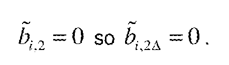
[0025] While the above-described embodiments of the present invention are directed to filters that have notches and resonances, the method of the present invention can be applied to the computation of any filter that is equivalent to a series of bi-quad filters. Similarly, any bi- quad stage can be used to implement a bilinear filter (with one pole and one zero) by setting, ai,2 and to 0. In this case,
Figure imgf000014_0002
Figure imgf000015_0008
resulting in coefficient values
b
Figure imgf000015_0001
[0026] The same filter structure as before could now be calculated. However, for improved precision, it is possible to change the computation of the Δ coefficients. For high sample rates compared to the dynamics to be filtered, then
Figure imgf000015_0002
which means that increased accuracy can be obtained by calculating:
Figure imgf000015_0003
, and finally
Figure imgf000015_0004
Figure imgf000015_0005
For this bi-quad section: where
Figure imgf000015_0006
Figure imgf000015_0007
where the coefficient, Ei, is chosen such that the multiplications have the desired precision and likewise where
Figure imgf000016_0002
Figure imgf000016_0001
Again, it is possible to select a different value ofな for each coefficient in the equations.
[0027] While embodiments above have discussed a single-input, single output (SISO) filter, it will be understood that this invention can be applied to filters with multiple inputs (MI) , multiple outputs (MO), or both (MIMO).
[0028] The software or logic blocks used to implement the present invention can optimized for state space implementation (such as Equations 28-30) or transfer function form implementations (such as Equations 17-24), or something in between (such as Equations 31-32). It will be clear from the discussion above that these computations can be implemented any of these, or other similar forms.
[0029] The above-described embodiments of the present invention have been provided to illustrate various aspects of the invention. However, it is to be understood that different aspects of the present invention that are shown in different specific embodiments can be combined to provide other embodiments of the present invention. In addition, various modifications to the present invention will become apparent from the foregoing description and accompanying drawings. Accordingly, the present invention is to be limited solely by the scope of the following claims.

Claims

WHAT IS CLAIMED IS:
1. A filter comprising any positive integer number of poles and zeros where this filter is equivalent to a plurality of bi-quad and/or bilinear filters connected in series, said filter being implemented on a digital processor that receives a sequence of signal values at a sampling rate characterized by a sampling interval and generates a filtered signal value upon receiving each received signal value, said filter having a latency that is less than said sampling interval.
2. The filter of Claim 1 wherein said filter is characterized by a number of parameters and wherein said latency is independent of said number of parameters.
3. The filter of Claim 1 wherein said processor generates each filtered signal value by adding a term to a received signal value and multiplying the sum by a gain constant that depends on said constants, wherein said term does not depend on said received signal value.

4. The filter of Claim 3 wherein said term depends on previously received signal values and constants characterizing said series-connected bi-quad filters.
5. The filter of Claim 1 wherein said plurality of bi-quad filters comprises a plurality of unit direct feedthrough gain bi-quad filters flowed by a gain stage.
6. The filter of Claim 5 wherein a plurality of the unit direct feedthrough gain bi-quad filters implements a bilinear filter.
7. The filter of Claim 3 wherein said processor generates said term utilized to compute the next filtered value prior to receiving the next signal value.
8. The filter of Claim 3 wherein said processor utilizes fixed-point integer arithmetic to compute said term.
9. The filter of Claim 8 wherein said bi-quad filter comprises a filter that provides a frequency notch or resonance at a predetermined frequency, said sampling rate being high compared to said predetermined frequency, and wherein said term is computed by multiplying one of said constants by a scaling factor prior to computing said term, said scaling factor being chosen to reduce round-off error in said term.
10. The filter of Claim 1 wherein said filter is implemented using a state space form.
11. The filter of Claim 1 wherein said filter is implemented using a transfer function form.
12. The filter method Claim 8 wherein said bi-quad filter comprises a filter that provides a shaping of the frequency response in a desired frequency range, said sampling rate being high compared to said desired frequency range, and wherein said term is computed by multiplying one of said constants by a scaling factor prior to computing said term, said scaling factor being chosen to reduce round-off error in said term.
13. A method for filtering a signal to generate a filtered signal that approximates the results of filtering said signal through a series connected string of bi-quad or bilinear filters, said method comprising: receiving a sequence of signal values at a sampling rate characterized by a sampling interval; generating a filtered signal value corresponding to each received signal value by adding a term to said received signal value and scaling the result to provide said filtered signal value, said term being independent of said corresponding received signal value; outputting said filtered signal value; and generating said term corresponding to said next signal value prior to receiving said next signal value.
14. The method of Claim 13 wherein said term depends on previously received signal values and constants characterizing said series-connected bi-quad filters.
15. The method of Claim 13 wherein generating said term comprises only arithmetic operations in fixed-point integer arithmetic.
16. The method of Claim 15 wherein said bi-quad filter comprises a filter that provides a frequency notch or resonance at a predetermined frequency, said sampling rate being high compared to said predetermined frequency, and wherein said term is computed by multiplying one of said constants by a scaling factor prior to computing said term, said scaling factor being chosen to reduce round-off error in said term.
17. The method of Claim 15 wherein said bi-quad filter comprises a filter that provides a shaping of the frequency response in a desired frequency range, said sampling rate being high compared to said desired frequency range, and wherein said term is computed by multiplying one of said constants by a scaling factor prior to computing said term, said scaling factor being chosen to reduce round-off error in said term.
18. The method of Claim 13 wherein a plurality of the unit direct feedthrough gain bi- quad filters implements a bilinear filter.
19. The method of Claim 13 wherein said filter is implemented using a state space form.
20. The method of Claim 13 wherein said filter is implemented using a transfer function form.
PCT/US2011/026555 2011-02-28 2011-02-28 Cascaded digital filters with reduced latency Ceased WO2012118483A1 (en)

Priority Applications (4)

Application Number Priority Date Filing Date Title
PCT/US2011/026555 WO2012118483A1 (en) 2011-02-28 2011-02-28 Cascaded digital filters with reduced latency
DE112011104978.1T DE112011104978T5 (en) 2011-02-28 2011-02-28 Cascaded digital filters with reduced latency
JP2013556593A JP2014511064A (en) 2011-02-28 2011-02-28 Cascade digital filter with reduced latency
US14/011,670 US9391590B2 (en) 2011-02-28 2013-08-27 Cascaded digital filters with reduced latency

Applications Claiming Priority (1)

Application Number Priority Date Filing Date Title
PCT/US2011/026555 WO2012118483A1 (en) 2011-02-28 2011-02-28 Cascaded digital filters with reduced latency

Related Child Applications (1)

Application Number Title Priority Date Filing Date
US14/011,670 Continuation US9391590B2 (en) 2011-02-28 2013-08-27 Cascaded digital filters with reduced latency

Publications (1)

Publication Number Publication Date
WO2012118483A1 true WO2012118483A1 (en) 2012-09-07

Family

ID=46758228

Family Applications (1)

Application Number Title Priority Date Filing Date
PCT/US2011/026555 Ceased WO2012118483A1 (en) 2011-02-28 2011-02-28 Cascaded digital filters with reduced latency

Country Status (3)

Country Link
JP (1) JP2014511064A (en)
DE (1) DE112011104978T5 (en)
WO (1) WO2012118483A1 (en)

Cited By (1)

* Cited by examiner, † Cited by third party
Publication number Priority date Publication date Assignee Title
US9678103B2 (en) 2011-10-28 2017-06-13 Keysight Technologies, Inc. Automatic tuning of atomic force microscope

Citations (3)

* Cited by examiner, † Cited by third party
Publication number Priority date Publication date Assignee Title
US5652770A (en) * 1992-09-21 1997-07-29 Noise Cancellation Technologies, Inc. Sampled-data filter with low delay
US6184748B1 (en) * 1998-09-30 2001-02-06 Lsi Logic Corporation Magnitude and group delay shaping circuit in continuous-time read channel filters
US20060129256A1 (en) * 2004-12-15 2006-06-15 Cirrus Logic, Incorporated Digital implementation of a fourth order linkwitz-riley network with a low cutoff frequency

Family Cites Families (4)

* Cited by examiner, † Cited by third party
Publication number Priority date Publication date Assignee Title
DE3886739D1 (en) * 1988-06-02 1994-02-10 Itt Ind Gmbh Deutsche Device for digital signal processing.
JP2659232B2 (en) * 1988-10-21 1997-09-30 日本電気株式会社 High dimensional digital filter
JPH0851338A (en) * 1994-05-31 1996-02-20 Icom Inc Band-pass ellipse digital filter system
JP2000285360A (en) * 1999-03-31 2000-10-13 Anritsu Corp Signal processor

Patent Citations (3)

* Cited by examiner, † Cited by third party
Publication number Priority date Publication date Assignee Title
US5652770A (en) * 1992-09-21 1997-07-29 Noise Cancellation Technologies, Inc. Sampled-data filter with low delay
US6184748B1 (en) * 1998-09-30 2001-02-06 Lsi Logic Corporation Magnitude and group delay shaping circuit in continuous-time read channel filters
US20060129256A1 (en) * 2004-12-15 2006-06-15 Cirrus Logic, Incorporated Digital implementation of a fourth order linkwitz-riley network with a low cutoff frequency

Cited By (1)

* Cited by examiner, † Cited by third party
Publication number Priority date Publication date Assignee Title
US9678103B2 (en) 2011-10-28 2017-06-13 Keysight Technologies, Inc. Automatic tuning of atomic force microscope

Also Published As

Publication number Publication date
JP2014511064A (en) 2014-05-01
DE112011104978T5 (en) 2014-01-23

Similar Documents

Publication Publication Date Title
Hogenauer An economical class of digital filters for decimation and interpolation
Bozic Digital and Kalman filtering
Middleton et al. Improved finite word length characteristics in digital control using delta operators
Lu et al. Optimal design of frequency-response-masking filters using semidefinite programming
Markel et al. Roundoff noise characteristics of a class of orthogonal polynomial structures
US11263293B2 (en) Digital sample rate conversion
JPH11261376A (en) Digital iir filter by few multipliers
Abramovitch The Multinotch, Part I: A low latency, high numerical fidelity filter for mechatronic control systems
Makundi et al. Closed-form design of tunable fractional-delay allpass filter structures
Rontogiannis et al. Multichannel fast QRD-LS adaptive filtering: New technique and algorithms
US9391590B2 (en) Cascaded digital filters with reduced latency
WO2012118483A1 (en) Cascaded digital filters with reduced latency
Abramovitch The multinotch, part II: Extra precision via Δ coefficients
Lopez et al. Sum-of-products Evaluation Schemes with Fixed-Point arithmetic, and their application to IIR filter implementation
Ohlsson et al. Implementation of low complexity FIR filters using a minimum spanning tree
US20130170585A1 (en) Biquad Infinite Impulse Response System Transformation
de Barcellos et al. Optimization of FRM filters using the WLS–Chebyshev approach
EP2651033B1 (en) Filter system
Karmakar et al. Design of an optimal two-channel orthogonal filterbank using semidefinite programming
Volkova et al. Fixed-point implementation of lattice wave digital filter: Comparison and error analysis
Deshpande et al. Highly narrow rejection bandwidth finite impulse response notch filters for communication
US7242326B1 (en) Sample rate conversion combined with filter
Chodoker et al. Multiple Constant Multiplication Technique for Configurable Finite Impulse Response Filter Design
Meyer-Baese Infinite impulse response (IIR) digital filters
US20080043889A1 (en) Exponentiated Polyphase Digital Filter

Legal Events

Date Code Title Description
121 Ep: the epo has been informed by wipo that ep was designated in this application

Ref document number: 11860056

Country of ref document: EP

Kind code of ref document: A1

ENP Entry into the national phase

Ref document number: 2013556593

Country of ref document: JP

Kind code of ref document: A

WWE Wipo information: entry into national phase

Ref document number: 1120111049781

Country of ref document: DE

Ref document number: 112011104978

Country of ref document: DE

122 Ep: pct application non-entry in european phase

Ref document number: 11860056

Country of ref document: EP

Kind code of ref document: A1