WO2012115041A1 - 表示装置の光学スペクトル設計方法および表示装置の製造方法 - Google Patents
表示装置の光学スペクトル設計方法および表示装置の製造方法 Download PDFInfo
- Publication number
- WO2012115041A1 WO2012115041A1 PCT/JP2012/053979 JP2012053979W WO2012115041A1 WO 2012115041 A1 WO2012115041 A1 WO 2012115041A1 JP 2012053979 W JP2012053979 W JP 2012053979W WO 2012115041 A1 WO2012115041 A1 WO 2012115041A1
- Authority
- WO
- WIPO (PCT)
- Prior art keywords
- color
- target
- luminance
- chromaticity coordinates
- optical spectrum
- Prior art date
- Legal status (The legal status is an assumption and is not a legal conclusion. Google has not performed a legal analysis and makes no representation as to the accuracy of the status listed.)
- Ceased
Links
Images










Classifications
-
- G—PHYSICS
- G02—OPTICS
- G02F—OPTICAL DEVICES OR ARRANGEMENTS FOR THE CONTROL OF LIGHT BY MODIFICATION OF THE OPTICAL PROPERTIES OF THE MEDIA OF THE ELEMENTS INVOLVED THEREIN; NON-LINEAR OPTICS; FREQUENCY-CHANGING OF LIGHT; OPTICAL LOGIC ELEMENTS; OPTICAL ANALOGUE/DIGITAL CONVERTERS
- G02F1/00—Devices or arrangements for the control of the intensity, colour, phase, polarisation or direction of light arriving from an independent light source, e.g. switching, gating or modulating; Non-linear optics
- G02F1/01—Devices or arrangements for the control of the intensity, colour, phase, polarisation or direction of light arriving from an independent light source, e.g. switching, gating or modulating; Non-linear optics for the control of the intensity, phase, polarisation or colour
- G02F1/13—Devices or arrangements for the control of the intensity, colour, phase, polarisation or direction of light arriving from an independent light source, e.g. switching, gating or modulating; Non-linear optics for the control of the intensity, phase, polarisation or colour based on liquid crystals, e.g. single liquid crystal display cells
- G02F1/133—Constructional arrangements; Operation of liquid crystal cells; Circuit arrangements
- G02F1/1333—Constructional arrangements; Manufacturing methods
- G02F1/1335—Structural association of cells with optical devices, e.g. polarisers or reflectors
- G02F1/1336—Illuminating devices
- G02F1/133602—Direct backlight
-
- G—PHYSICS
- G02—OPTICS
- G02F—OPTICAL DEVICES OR ARRANGEMENTS FOR THE CONTROL OF LIGHT BY MODIFICATION OF THE OPTICAL PROPERTIES OF THE MEDIA OF THE ELEMENTS INVOLVED THEREIN; NON-LINEAR OPTICS; FREQUENCY-CHANGING OF LIGHT; OPTICAL LOGIC ELEMENTS; OPTICAL ANALOGUE/DIGITAL CONVERTERS
- G02F1/00—Devices or arrangements for the control of the intensity, colour, phase, polarisation or direction of light arriving from an independent light source, e.g. switching, gating or modulating; Non-linear optics
- G02F1/01—Devices or arrangements for the control of the intensity, colour, phase, polarisation or direction of light arriving from an independent light source, e.g. switching, gating or modulating; Non-linear optics for the control of the intensity, phase, polarisation or colour
- G02F1/13—Devices or arrangements for the control of the intensity, colour, phase, polarisation or direction of light arriving from an independent light source, e.g. switching, gating or modulating; Non-linear optics for the control of the intensity, phase, polarisation or colour based on liquid crystals, e.g. single liquid crystal display cells
- G02F1/133—Constructional arrangements; Operation of liquid crystal cells; Circuit arrangements
- G02F1/1333—Constructional arrangements; Manufacturing methods
- G02F1/1335—Structural association of cells with optical devices, e.g. polarisers or reflectors
- G02F1/1336—Illuminating devices
- G02F1/133624—Illuminating devices characterised by their spectral emissions
-
- G—PHYSICS
- G09—EDUCATION; CRYPTOGRAPHY; DISPLAY; ADVERTISING; SEALS
- G09G—ARRANGEMENTS OR CIRCUITS FOR CONTROL OF INDICATING DEVICES USING STATIC MEANS TO PRESENT VARIABLE INFORMATION
- G09G3/00—Control arrangements or circuits, of interest only in connection with visual indicators other than cathode-ray tubes
- G09G3/20—Control arrangements or circuits, of interest only in connection with visual indicators other than cathode-ray tubes for presentation of an assembly of a number of characters, e.g. a page, by composing the assembly by combination of individual elements arranged in a matrix no fixed position being assigned to or needed to be assigned to the individual characters or partial characters
- G09G3/2003—Display of colours
Definitions
- the present invention relates to a method for designing an optical spectrum of a display device.
- the present invention also relates to a method for manufacturing a display device.
- Patent Document 1 discloses a liquid crystal display device in which one color display pixel is configured by four or more pixels displaying different colors.
- a display device that performs display using three primary colors that is, a conventional general
- a display device and a liquid crystal display device that use four or more primary colors for display They are called “multi-primary color display devices” and “multi-primary color liquid crystal display devices”, respectively.
- the original display performance of the display device can be improved as much as possible by adjusting the luminance and chromaticity reproducibility of monochromatic and white display and the luminance and chromaticity reproducibility of halftone display. Need to pull out.
- it is ideal to design the optical spectrum of the display device optimally for monochromatic and white.
- display efficiency light use efficiency
- the optical spectrum is characterized by the emission spectrum of the backlight and the transmission spectrum of the color filter.
- the present invention has been made in view of the above problems, and an object thereof is to provide an optical spectrum design method for a display device capable of designing an optimal optical spectrum for a target luminance and chromaticity. It is in.
- An optical spectrum design method for a display device includes a plurality of pixels including a first pixel that displays a first color and a second pixel that displays a second color different from the first color.
- An optical spectrum design method for a display device having color display pixels, the first target luminance and first target chromaticity coordinates being the target luminance and chromaticity coordinates for the first color, and the second Setting a second target brightness and a second target chromaticity coordinate, which are target brightness and chromaticity coordinates for a color, at least the first target brightness, the first target chromaticity coordinates, Based on the second target luminance and the second target chromaticity coordinates, and the chromaticity coordinates of a plurality of points located on a first straight line connecting the first target chromaticity coordinates and the second target chromaticity coordinates. Perform calculations on optical spectra Comprising the step (b), a.
- the step (b) is based on the first target luminance, the first target chromaticity coordinate, the second target luminance, and the second target chromaticity coordinate.
- An arbitrary spectrum is assumed as the step (b1) of calculating chromaticity coordinates of the plurality of points positioned above, and the first spectrum corresponding to the first color and the second spectrum corresponding to the second color (B2) calculating chromaticity coordinates of the plurality of points located on the first straight line based on the assumed arbitrary spectrum, and the chromaticity calculated by the step (b1) And (b3) performing a calculation using the coordinates and the chromaticity coordinates calculated in the step (b2).
- the luminance of the first color and the luminance of the second color are also calculated in the step (b2) based on the assumed arbitrary spectrum, and in the step (b3) The calculation is also performed using the luminance of the first color and the luminance of the second color calculated in the step (b2).
- the plurality of pixels further include a third pixel that displays a third color different from the first color and the second color.
- the optical spectrum designing method of the display device sets a third target luminance and a third target chromaticity coordinate, which are target luminance and chromaticity coordinates for the third color.
- Step (c) at least the second target luminance, the second target chromaticity coordinate, the third target luminance and the third target chromaticity coordinate, the second target chromaticity coordinate, and the third target chromaticity
- Step (d) further performing a further calculation relating to the optical spectrum based on the chromaticity coordinates of a plurality of points located on the second straight line connecting the coordinates.
- the step (d) includes the second straight line based on the second target luminance, the second target chromaticity coordinate, the third target luminance, and the third target chromaticity coordinate.
- An arbitrary spectrum is assumed as a step (d1) of calculating chromaticity coordinates of the plurality of points positioned above, a second spectrum corresponding to the second color, and a third spectrum corresponding to the third color (D2) calculating chromaticity coordinates of the plurality of points located on the second straight line based on the assumed arbitrary spectrum, and the chromaticity calculated by the step (d1) And (d3) performing a calculation using the coordinates and the chromaticity coordinates calculated in the step (d2).
- the luminance of the second color and the luminance of the third color are also calculated based on the assumed arbitrary spectrum, and in the step (d3) The calculation is performed using the luminance of the second color and the luminance of the third color calculated in the step (d2).
- the optical spectrum designing method for a display device includes, after the step (d), the third target luminance, the third target chromaticity coordinate, the first target luminance, and the first target luminance. Based on the target chromaticity coordinates and the chromaticity coordinates of a plurality of points located on the third straight line connecting the third target chromaticity coordinates and the first target chromaticity coordinates, further calculation regarding the optical spectrum is performed. Step (e) is further included.
- the plurality of pixels further includes a third pixel that displays a third color different from the first color and the second color
- Third target luminance and third target chromaticity coordinates which are target luminance and chromaticity coordinates for the three colors, are also set
- step (b) the third target luminance and the third target chromaticity coordinates are set.
- the calculation is also performed based on the chromaticity coordinates of a plurality of points located on the third straight line connecting the coordinates.
- the step (b) includes the first target luminance, the first target chromaticity coordinate, the second target luminance, the second target chromaticity coordinate, the third target luminance, and the first target luminance.
- the step (b1) Based on three target chromaticity coordinates, chromaticity coordinates of the plurality of points located on the first straight line, chromaticity coordinates of the plurality of points located on the second straight line, and the third straight line A step (b1) of calculating chromaticity coordinates of the plurality of points positioned above; a first spectrum corresponding to the first color; a second spectrum corresponding to the second color; and the third color.
- An arbitrary spectrum is assumed as the third spectrum corresponding to, and based on the assumed arbitrary spectrum, chromaticity coordinates of the plurality of points located on the first straight line, on the second straight line,
- the chromaticity coordinates of the plurality of points located and the third straight line Calculation is performed using the step (b2) of calculating chromaticity coordinates of the plurality of points located, the chromaticity coordinates calculated by the step (b1), and the chromaticity coordinates calculated by the step (b2). Step (b3).
- the luminance of the first color, the luminance of the second color, and the luminance of the third color are also calculated based on the assumed arbitrary spectrum.
- the calculation is performed using the luminance of the first color, the luminance of the second color, and the luminance of the third color calculated in the step (b2).
- the plurality of pixels further include a fourth pixel that displays a fourth color different from the first color, the second color, and the third color.
- the optical spectrum designing method of the display device sets a fourth target luminance and a fourth target chromaticity coordinate, which are target luminance and chromaticity coordinates for the fourth color.
- Step (f) the third target luminance, the third target chromaticity coordinate, the fourth target luminance and the fourth target chromaticity coordinate, the third target chromaticity coordinate, and the fourth target chromaticity coordinate
- Step (g) further performing a calculation relating to the optical spectrum based on the chromaticity coordinates of a plurality of points located on the third straight line connecting the two.
- the step (g) is based on the third target luminance, the third target chromaticity coordinate, the fourth target luminance, and the fourth target chromaticity coordinate.
- An arbitrary spectrum is assumed as the step (g1) of calculating chromaticity coordinates of the plurality of points positioned above, the third spectrum corresponding to the third color, and the fourth spectrum corresponding to the fourth color And (g2) calculating chromaticity coordinates of the plurality of points located on the third straight line based on the assumed arbitrary spectrum, and the chromaticity calculated by the step (g1) And (g3) performing a calculation using the coordinates and the chromaticity coordinates calculated in the step (g2).
- the luminance of the third color and the luminance of the fourth color are also calculated based on the assumed arbitrary spectrum, and in the step (g3) The calculation is performed using the luminance of the third color and the luminance of the fourth color calculated in the step (g2).
- the optical spectrum designing method for a display device includes, after the step (g), the fourth target luminance, the fourth target chromaticity coordinate, the first target luminance, and the first target luminance. Based on the target chromaticity coordinates and the chromaticity coordinates of a plurality of points located on the fourth straight line connecting the fourth target chromaticity coordinates and the first target chromaticity coordinates, further calculation regarding the optical spectrum is performed. Step (h) is further included.
- the plurality of pixels include a third pixel that displays a third color different from the first color and the second color, the first color, and the second color. And a fourth pixel that displays a fourth color different from the third color, and in the step (a), a third brightness and chromaticity coordinates that are targeted for the third color.
- a target luminance and third target chromaticity coordinates, and a fourth target luminance and fourth target chromaticity coordinates, which are target luminance and chromaticity coordinates for the fourth color, are also set.
- step (b) A second straight line connecting the third target luminance, the third target chromaticity coordinate, the fourth target luminance and the fourth target chromaticity coordinate, and the second target chromaticity coordinate and the third target chromaticity coordinate.
- the calculation is performed based on the chromaticity coordinates of the point.
- the first target luminance, the first target chromaticity coordinate, the second target luminance, the second target chromaticity coordinate, the third target luminance Based on three target chromaticity coordinates, the fourth target luminance, and the fourth target chromaticity coordinates, the chromaticity coordinates of the plurality of points located on the first straight line are located on the second straight line Calculating chromaticity coordinates of the plurality of points, chromaticity coordinates of the plurality of points located on the third straight line, and chromaticity coordinates of the plurality of points located on the fourth straight line (b1) ), A first spectrum corresponding to the first color, a second spectrum corresponding to the second color, a third spectrum corresponding to the third color, and a fourth spectrum corresponding to the fourth color Assuming an arbitrary spectrum, and based on the assumed arbitrary spectrum The chromaticity coordinates of the plurality of points located on the first straight line, the chromaticity coordinates of the plurality of points located on the first straight line, the chromaticity coordinates
- the luminance of the first color, the luminance of the second color, the luminance of the third color, and the The luminance of the fourth color is also calculated.
- the luminance of the first color, the luminance of the second color, the luminance of the third color calculated in the step (b2) and The calculation is also performed using the luminance of the fourth color.
- the optical spectrum designing method of the display device sets a predetermined quadratic function for the optical spectrum calculated by the step (b), and the optical spectrum has a certain variation.
- the method further includes the step (i) of determining whether or not the quadratic function is a symmetric quadratic function when a value is added.
- the plurality of pixels include a red pixel that displays red, a green pixel that displays green, and a blue pixel that displays blue.
- the plurality of pixels further include a yellow pixel that displays yellow.
- a manufacturing method of a display device includes a step (A) of designing an optical spectrum by the optical spectrum design method of the display device and a step (B) of manufacturing a display device having the designed optical spectrum. To do.
- the display device produced in the step (B) is a liquid crystal display device.
- the liquid crystal display device includes a lighting element and a color filter
- the step (B) includes a step of preparing the lighting element and the color filter so that the optical spectrum is realized. (B1) is included.
- an optical spectrum design method for a display device capable of designing an optimal optical spectrum for a target luminance and chromaticity.
- (A) is a graph which shows an example of the optical spectrum which is not optimal
- (b) is chromaticity which shows the color reproduction range of the display apparatus which has the optical spectrum shown to (a), and the color reproduction range of a design target.
- FIG. It is a graph which shows the relationship between the function F and the variation
- the present invention has been made in consideration of the above problems (i) to (iii).
- the optical spectrum design method in a preferred embodiment of the present invention will be described while more specifically describing the problems (i) to (iii).
- the overline indicated in the mathematical expression is indicated by a superscript dash “ — ” in the text for convenience. For example, over the line is attached "A”, the sentence - is denoted as "A”.
- Chromaticity coordinates can be expressed using tristimulus values (X, Y, Z).
- the tristimulus values (X, Y, Z) are calculated using the color matching function (x ⁇ ( ⁇ ), y ⁇ ( ⁇ ), z ⁇ ( ⁇ )) for the wavelength ⁇ and the optical spectral function ⁇ ( ⁇ ). These are expressed by three different expressions as in the following formulas (1), (2) and (3).
- Color matching functions (x - ( ⁇ ), y - ( ⁇ ), z - ( ⁇ )) , such as shown in FIG. 1, the spectral sensitivity curve corresponding to the human eye. Further, the chromaticity coordinates (u C ′, v C ′) are specifically expressed as the following formula (4) using tristimulus values (X, Y, Z).
- Equations (5) and (6) which are linear equations for the optical spectrum, are expressed in the form of inner products of multidimensional vectors. Therefore, it is impossible to determine an optical spectrum having four or more dimensions (that is, four or more wavelengths) with respect to the chromaticity coordinates (u C ′, v C ′).
- the above two conditions are equations that give a multidimensional surface, so that the intensity value of the optical spectrum cannot be uniquely determined. Therefore, it is not possible to determine an optimal optical spectrum that realizes an arbitrary chromaticity coordinate (u C ', v C '). Therefore, an optical spectrum over a wavelength range of 350 nm to 750 nm (that is, in the visible region) cannot be obtained in a practical unit (about 1 nm).
- the degree of freedom of the optical spectrum is too large compared to the number of conditions (due to the color matching relationship), so the optical spectrum is uniquely determined. It cannot be determined. Therefore, even if the optical spectrum as shown in FIG. 2A is forcibly designed on the condition of the luminance and chromaticity of a certain color, the actual luminance and chromaticity of the display device, the target luminance and As shown in FIG. 2B, the color reproduction range of the actual display device becomes narrower than the design target color reproduction range.
- Equation (5) a case corresponding to Equation (5) is taken as an example.
- a quadratic function F expressed by the following equation (7).
- Equation (6) a case corresponding to Equation (6) will be described.
- Equation (6) a quadratic function G expressed by the following equation (10).
- Equation (11) becomes the following Equation (12).
- the values of the functions F and G are calculated by superimposing an optical spectrum having a constant intensity value regardless of the wavelength on the target optical spectrum, and the calculated function value is an extreme value with respect to the variation value. And is symmetrical, it can be determined that the target optical spectrum is the optimal optical spectrum.
- the chromaticity coordinates of a single red color are (u R ', v R '), and the chromaticity coordinates of a green single color are (u G ', v G ').
- the red monochromatic optical spectrum be ⁇ R ( ⁇ )
- the green monochromatic optical spectrum be ⁇ G ( ⁇ ).
- a parameter is introduced for the optical spectrum that changes its intensity between 0 and 1 times.
- the parameter for the red monochromatic optical spectrum ⁇ R ( ⁇ ) is C R
- the parameter for the green monochromatic optical spectrum ⁇ G ( ⁇ ) is C G.
- the chromaticity coordinates (u ′, v ′) represented by the equation (15) are the red chromaticity coordinates (u R ′, v R ′) and the green chromaticity coordinates (u G ′, v Prove that it lies on a straight line connecting G ').
- the equation of this straight line is expressed as the following equation (16).
- Expression (15) When Expression (15) is substituted into Expression (16), the left side of Expression (16) is represented by the following Expression (17), and the right side of Expression (16) is represented by the following Expression (18).
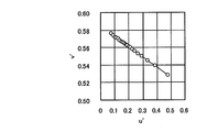
- Figure 4 shows the actual equation (15) the parameters C R and C G is changed by chromaticity coordinates (u ', v') in the results of plotting.
- the luminance of the red single color is 25 nits
- the luminance of the green single color is 75 nits.
- FIG. 4 shows that when obtaining the optical spectrum, the target red chromaticity coordinates (u R ', v R ') and the green chromaticity coordinates (u G ', v G ') are obtained. This means that a plurality of points located on a connecting straight line can be used as a condition. Therefore, it can be seen that many conditions necessary for obtaining the optical spectrum can be prepared.
- FIG. 4 shows the actual equation (15) the parameters C R and C G is changed by chromaticity coordinates (u ', v') in the results of plotting.
- the luminance of the red single color is 25 nits
- the luminance of the green single color is 75 nits.
- FIG. 4 shows
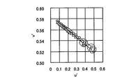
- FIG. 5 shows the result of calculating and plotting the chromaticity coordinates based on the non-optimal optical spectrum (triangles in FIG. 5).
- FIG. 5 also shows the plot results shown in FIG. 4 for comparison (circles in FIG. 5).
- the chromaticity coordinates calculated from the non-optimal optical spectrum are offset from the target chromaticity coordinates.
- the target luminance and chromaticity coordinates are (Y R , u R ', v R ') for the red color, and (Y G , u G ', v G ') for the green color.
- a red monochromatic spectrum is represented by ⁇ ⁇ R ( ⁇ )
- a green monochromatic optical spectrum is represented by ⁇ ⁇ G ( ⁇ ).
- the optimal optical spectrum design is treated as a multivariable optimization problem.
- the variables are a red monochromatic optical spectrum ⁇ - R ( ⁇ ) and a green monochromatic optical spectrum ⁇ - G ( ⁇ ).
- the condition is a value of chromaticity coordinates (u ′, v ′).
- the condition of the spectrum intensity C is (2N ⁇ 1) as represented by the following formula (19) in the case of two colors, where N is an integer.
- the number of optimization problem conditions is 2 (2N ⁇ 1). Furthermore, if Y R and Y G are added to the conditions, the number of optimization problem conditions is 4N. Therefore, 2N variables can be set for each of the red monochromatic optical spectrum and the green monochromatic optical spectrum. In order to obtain the optical spectrum, the following two types of calculations (first calculation and second calculation) are performed.
- Second calculation Assuming an arbitrary optical spectrum ⁇ ⁇ R ( ⁇ ) and ⁇ ⁇ G ( ⁇ ), C R and C G having the same values as the parameters in the first calculation are used, and C R ⁇ ⁇ R ( lambda) and C G phi - for G (lambda), the chromaticity coordinates (u - ', v -' ) is calculated.
- the overline indicates that the calculation is performed using a spectrum.
- the luminance and chromaticity coordinates of the red single color calculated from the spectrum are (Y ⁇ R , u ⁇ R ', v ⁇ R '), and the luminance and chromaticity coordinates of the green single color are (Y ⁇ G , u ⁇ G ', v - 'When), the chromaticity coordinates (u -' G, v - ') is expressed as the following equation (20).
- the luminances Y - R and Y - G can be obtained from Equation (2).
- equations (21) to (24) are rewritten ignoring the term O ( ⁇ ⁇ 2 ), simultaneous equations relating to ⁇ ⁇ R ( ⁇ ) and ⁇ ⁇ G ( ⁇ ) can be obtained.
- O ( ⁇ ⁇ 2 ) the left side of the equations (21) and (22) matches (u ′, v ′) expressed by the equations (13) and (14).
- specific equation such as Equation (25), ⁇ - R ( ⁇ ) and .delta..phi - the simultaneous equations relating G (lambda).
- Equation (25) which is a simultaneous equation with ⁇ ⁇ R ( ⁇ ) and ⁇ ⁇ G ( ⁇ ) as solutions, is an enormous matrix having 16N 2 elements. Therefore, if the optical spectrum is properly calculated, 2N ⁇ 3 integration is required for calculating the matrix element. As a result, the approximate total calculation amount is as large as 96N 3 . In order to facilitate this calculation, the amount of calculation is reduced using equations (1) to (3), (13) and (14).
- equations similar to equations (26) and (27) can be obtained using equation (14).
- the LU decomposition method of simultaneous equations can be used.
- the second calculation is repeated with ⁇ ⁇ R ( ⁇ ) + ⁇ ⁇ R ( ⁇ ) and ⁇ ⁇ G ( ⁇ ) + ⁇ ⁇ G ( ⁇ ) obtained from the simultaneous equations as a new optical spectrum,
- the resulting optical spectrum can be reached at the target (ie, optimal) optical spectrum. This means that the chromaticity coordinates calculated from the obtained optical spectrum become the target chromaticity coordinates as indicated by arrows in FIG.
- the optical spectrum of the display device that performs display using three or more primary colors is designed. To do this, there are two methods (I) and (II) below.
- the spectrum determination algorithm for two colors is sequentially applied to the combination of the two primary colors.
- the optical spectrum is calculated for a combination of red and green first, then for a combination of green and blue, and then blue and red What is necessary is just to carry out about the combination of.
- the optical spectrum is calculated first for the combination of red and yellow, and then for the combination of yellow and green. Subsequently, the combination of green and blue may be performed, and finally the combination of blue and red may be performed.
- the spectrum determination algorithm for two colors is extended and applied to combinations of all three or more primary colors. For example, in the case of a display device that performs color display using three colors of red, green, and blue, the optical spectrum is calculated simultaneously for combinations of red, green, and blue. Similarly, in the case of a display device that performs color display using four colors of red, yellow, green, and blue, the optical spectrum is calculated simultaneously for combinations of red, yellow, green, and blue.
- the target luminance and chromaticity coordinates are (Y R , u R ', v R '), (Y Ye , u Ye ', v Ye '), ( Y G , u G ', v G ') and (Y B , u B ', v B ').
- the red monochromatic, yellow monochromatic, green monochromatic and blue monochromatic spectra are respectively ⁇ ⁇ R ( ⁇ ), ⁇ ⁇ Ye ( ⁇ ), ⁇ ⁇ G ( ⁇ ) and ⁇ ⁇ B ( ⁇ ).
- Optimal optical spectrum design in the case of four colors is also treated as a multivariable optimization problem, as in the case of two colors.
- the variables are the optical spectrums ⁇ - R ( ⁇ ), ⁇ - Ye ( ⁇ ), ⁇ - G ( ⁇ ), and ⁇ - B ( ⁇ ) of red monochromatic, yellow monochromatic, green monochromatic and blue monochromatic.
- the condition is a value of chromaticity coordinates (u ′, v ′). If the parameters for changing the intensity of the optical spectrum are C R , C Ye , C G and C B for red, yellow, green and blue, respectively, the condition of the spectrum intensity C is 4 colors.
- the number is 4 (2N-1) as represented by the following formula (28).
- (4N ⁇ 1) variables can be set for each of the optical spectrums of red single color, yellow single color, green single color, and blue single color. Similarly, in the case of three colors, (4N ⁇ 1) variables can be set for the optical spectrum of each primary color.
- the subscript k takes a value from 1 to (4N-1), and the subscript i takes a value from 1 to (2N-1). Therefore, the size of the determinant on the left side of Equation (29) is 4 (4N ⁇ 1) ⁇ 4 (4N ⁇ 1) (that is, the determinant on the left side is 4 (4N ⁇ 1) ⁇ 4 (4N ⁇ 1)). However, the amount of calculation can be reduced by a method similar to that described for Equation (25).
- Equation (29) is a simultaneous equation with ⁇ - R ( ⁇ ), ⁇ - Ye ( ⁇ ), ⁇ - G ( ⁇ ), and ⁇ - B ( ⁇ ) as a solution
- the LU decomposition method can be used.
- ⁇ - R ( ⁇ ) + ⁇ - R ( ⁇ ), ⁇ - Ye ( ⁇ ) + ⁇ - Ye ( ⁇ ), ⁇ - G ( ⁇ ) + ⁇ - G ( ⁇ ) and ⁇ - B By repeating the second calculation using ( ⁇ ) + ⁇ ⁇ B ( ⁇ ) as a new optical spectrum, the optical spectrum obtained by the calculation can reach the target (that is, optimal) optical spectrum.
- the chromaticity coordinates calculated from the obtained optical spectrum are the target chromaticity coordinates as shown by arrows in FIG. 5 for the case of two colors.
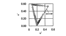
- an optimal optical spectrum can be designed for three or more colors. Therefore, for a case of three colors, for example, if a design target as shown in FIG.
- the optical spectrum as shown in FIG. 7 can be designed as an optimum optical spectrum of green and blue. Therefore, as indicated by an arrow in FIG. 8, the color reproduction range of the display device can be brought close to the design target.
- the chromaticity of white can also be determined.
- the relationship between the chromaticity coordinates of each primary color and the chromaticity coordinates of white will be described by taking the case of four colors as an example.
- Tristimulus values of red single color, yellow single color, green single color and blue single color are (X R , Y R , Z R ), (X Ye , Y Ye , Z Ye ), (X G , Y G , Z G ) and (X B , Y B , Z B ).
- the parameters for changing the intensity between 0 and 1 times are C R , C Ye , C G and C B for each of the red single color, yellow single color, green single color and blue single color.
- white chromaticity coordinates (u W ′, v W ′) can be expressed as in the following equations (30) and (31).
- C W X W , C W Y W and C W Z W are represented by the following formulas (32), (33) and (34).
- the chromaticity of white (u W ′, v W ′) is the weighted average of C C Y C / v C ′ for the chromaticity (u C ′, v C ′) of each primary color.
- the optical spectrum design method in the present embodiment is a color display pixel configured by a plurality of pixels including a first pixel that displays a first color and a second pixel that displays a second color different from the first color.
- An optical spectrum design method for a display device having The display device is, for example, a liquid crystal display device as will be described later, but is not limited to this.
- various displays such as an organic EL display device and a plasma display.
- An optical spectrum can be designed for the device.
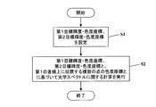
- FIG. 9 is a flowchart of the optical spectrum design method in the present embodiment.
- first target luminance and chromaticity coordinates for the first color (hereinafter referred to as “first target luminance” and “first target chromaticity coordinates”, respectively), and target luminance for the second color And chromaticity coordinates (hereinafter referred to as “second target luminance” and “second target chromaticity coordinates”, respectively) are set (step S1).
- step S2 based on the set first target luminance, first target chromaticity coordinates, second target luminance, and second target chromaticity coordinates, a calculation relating to the optical spectrum is performed (step S2).
- step S2 not only the above-described set luminance and chromaticity coordinates, but also a position on a straight line (referred to as a “first straight line” for convenience) connecting the first target chromaticity coordinates and the second target chromaticity coordinates.
- Step S2 corresponds to the method already described with reference to equations (13) to (27). For example, when the first color is red and the second color is green, equations (13) to ( 27) is performed, whereby the optical spectrum is determined.
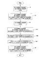
- FIG. 10 is a flowchart showing the step S2 more specifically.
- step S1 first, based on the first target luminance, the first target chromaticity coordinates, the second target luminance, and the second target chromaticity coordinates, the chromaticity coordinates of a plurality of points located on the first straight line are determined.
- step S2A can be performed using, for example, the equation (15) (corresponding to the “first calculation” already described).
- step S2B an arbitrary spectrum is assumed as the first spectrum corresponding to the first color and the second spectrum corresponding to the second color, and located on the first straight line based on the assumed arbitrary spectrum
- the chromaticity coordinates of a plurality of points are calculated (step S2B).
- This step S2B can be performed using, for example, the equation (20) (corresponding to the “second calculation” already described).
- step S2C calculation is performed using the chromaticity coordinates calculated in step S2A and the chromaticity coordinates calculated in step S2B (step S2C).
- This step S2C is equivalent to solving simultaneous equations as shown by, for example, the equation (25).
- Step S2A and S2B are executed are not limited to the example of FIG. Step S2B may be executed before step S2A.
- step S2B in addition to the chromaticity coordinates of a plurality of points located on the first straight line, the luminance of the first color and the luminance of the second color are calculated based on the assumed arbitrary spectrum. It is preferable. For example, from equation (2), the luminance of the first color and the luminance of the second color can be calculated. The calculation of the luminance of the first color and the luminance of the second color in the step S2B and the calculation using those luminances in the step S2C also increases the number of conditions in the multivariable optimization problem. (Y - R , Y in the matrix in Equation (25), which is a simultaneous equation) ( Note that there are elements that contain G ).
- the plurality of pixels constituting the color display pixel of the display device further includes a third pixel that displays a third color different from the first color and the second color.
- the plurality of pixels constituting the color display pixel include, for example, a red pixel that displays red, a green pixel that displays green, and a blue pixel that displays blue.
- FIG. 11 is a flowchart of an optical spectrum design method for three colors.
- Step S2 may include steps S2A, S2B, and S2C shown in FIG.
- step S3 target luminance and chromaticity coordinates for the third color (hereinafter referred to as “third target luminance” and “third target chromaticity coordinates”, respectively) are set.
- step S4 the second target luminance, the second target chromaticity coordinate, the third target luminance and the third target chromaticity coordinate, and a straight line connecting the second target chromaticity coordinate and the third target chromaticity coordinate (for convenience, “second Based on the chromaticity coordinates of a plurality of points located on the straight line (referred to as a “straight line”), further calculations regarding the optical spectrum are performed (step S4).
- the third target luminance, the third target chromaticity coordinate, the first target luminance and the first target chromaticity coordinate, and a straight line connecting the third target chromaticity coordinate and the first target chromaticity coordinate (for convenience, the “third straight line” Further calculation regarding the optical spectrum is performed based on the chromaticity coordinates of a plurality of points located above (refer to step S5).
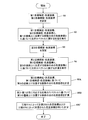
- FIG. 12 is a flowchart showing the step S4 more specifically.
- step S3 After step S3, first, based on the second target luminance, the second target chromaticity coordinate, the third target luminance, and the third target chromaticity coordinate, the chromaticity coordinates of a plurality of points located on the second straight line are determined. Calculate (step S4A).
- step S4C calculation is performed using the chromaticity coordinates calculated in step S4A and the chromaticity coordinates calculated in step S4B (step S4C).
- Step S4A and S4B are executed are not limited to the example of FIG. Step S4B may be executed before step S4A.
- step S4B based on the assumed arbitrary spectrum, the luminance of the second color and the luminance of the third color are calculated in addition to the chromaticity coordinates of a plurality of points located on the second straight line. It is preferable.
- the calculation of the luminance of the second color and the luminance of the third color in step S4B and the calculation using these luminances in step S4C also increases the number of conditions in the multivariable optimization problem. Because it will not be.
- step S5 will be described more specifically with reference to FIG.
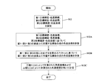
- FIG. 13 is a flowchart more specifically showing step S5.
- step S4 first, based on the third target luminance, the third target chromaticity coordinate, the first target luminance, and the first target chromaticity coordinate, the chromaticity coordinates of a plurality of points located on the third straight line are determined. Calculate (step S5A).
- an arbitrary spectrum is assumed as the third spectrum corresponding to the third color and the first spectrum corresponding to the first color, and is located on the third straight line based on the assumed arbitrary spectrum.
- the chromaticity coordinates of a plurality of points are calculated (step S5B).
- step S5C calculation is performed using the chromaticity coordinates calculated in step S5A and the chromaticity coordinates calculated in step S5B (step S5C).
- Step S5A and S5B are executed is not limited to the example in FIG. Step S5B may be performed before step S5A.
- step S5B based on the assumed arbitrary spectrum, the luminance of the third color and the luminance of the first color are calculated in addition to the chromaticity coordinates of a plurality of points located on the third straight line. It is preferable.
- the calculation of the luminance of the third color and the luminance of the first color in step S5B and the calculation using these luminances in step S5C also increase the number of conditions in the multivariable optimization problem. Because it will not be.
- optical spectrum design method described with reference to FIGS. 11, 12, and 13 is a method of sequentially applying the spectrum determination algorithm for two colors to a combination of two primary colors (the method (I) already described). Equivalent to Of course, an optical spectrum design method in which the spectrum determination algorithm for two colors is applied to a combination of three primary colors may be adopted (corresponding to the method (II) already described). Hereinafter, such an optical spectrum design method will be described with reference to FIG.
- a first target luminance, a first target chromaticity coordinate, a second target luminance, a second target chromaticity coordinate, a third target luminance, and a third target chromaticity coordinate are set (step S11).
- Step S12 a calculation relating to the optical spectrum is performed based on the set first target luminance, first target chromaticity coordinates, second target luminance, second target chromaticity coordinates, third target luminance, and third target chromaticity coordinates.
- Step S12 not only the above-described set luminance and chromaticity coordinates, but also the chromaticity coordinates of a plurality of points located on the first straight line and the colors of the plurality of points located on the second straight line.
- Calculations are also performed based on the degree coordinates and the chromaticity coordinates of a plurality of points located on the third straight line.
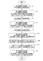
- FIG. 15 is a flowchart showing the step S12 more specifically.
- step S11 After step S11, first, based on the first target luminance, the first target chromaticity coordinates, the second target luminance, the second target chromaticity coordinates, the third target luminance, and the third target chromaticity coordinates, the first straight line
- the chromaticity coordinates of the plurality of points located above, the chromaticity coordinates of the plurality of points located on the second straight line, and the chromaticity coordinates of the plurality of points located on the third straight line are calculated (step S12A). .
- an arbitrary spectrum is assumed as the first spectrum corresponding to the first color, the second spectrum corresponding to the second color, and the third spectrum corresponding to the third color.
- the chromaticity coordinates of a plurality of points located on the first straight line Based on the chromaticity coordinates of a plurality of points located on the first straight line, the chromaticity coordinates of the plurality of points located on the second straight line, and the chromaticity coordinates of the plurality of points located on the third straight line Is calculated (step S12B).
- step S12C calculation is performed using the chromaticity coordinates calculated in step S12A and the chromaticity coordinates calculated in step S12B (step S12C).
- Step S12A and S12B are performed is not limited to the example of FIG. Step S12B may be performed before step S12A.
- step S12B based on the assumed arbitrary spectrum, in addition to the chromaticity coordinates of a plurality of points located on the first, second and third straight lines, the luminance of the first color, the second It is preferred to calculate the luminance of the color and the luminance of the third color.
- the luminance of the first color, the luminance of the second color, and the luminance of the third color are calculated in step S12B, and calculation is also performed using these luminances in step S12C. This is because there is nothing but increasing the number of conditions.
- the plurality of pixels constituting the color display pixel of the display device may further include a fourth pixel that displays a fourth color different from the first color, the second color, and the third color. That is, the display device may be a multi-primary color display device.
- the plurality of pixels constituting the color display pixel of the multi-primary color display device include, for example, a yellow pixel that displays yellow in addition to a red pixel, a green pixel, and a blue pixel.
- the plurality of pixels constituting the color display pixel may include a cyan pixel for displaying cyan and a magenta pixel for displaying magenta instead of the yellow pixel.
- FIG. 16 is a flowchart of an optical spectrum design method in the case of four colors.
- Step S2 may include steps S2A, S2B, and S2C shown in FIG. 10
- step S4 may include steps S4A, S4B, and S4C shown in FIG.
- step S6 target luminance and chromaticity coordinates for the fourth color (hereinafter referred to as “fourth target luminance” and “fourth target chromaticity coordinates”, respectively) are set.
- step S7 the third target luminance, the third target chromaticity coordinate, the fourth target luminance and the fourth target chromaticity coordinate, and a straight line connecting the third target chromaticity coordinate and the fourth target chromaticity coordinate (for convenience, “third Further calculation regarding the optical spectrum is performed based on the chromaticity coordinates of a plurality of points located on the straight line (referred to as “straight line”) (step S7).
- the fourth target luminance, the fourth target chromaticity coordinate, the first target luminance and the first target chromaticity coordinate, and a straight line connecting the fourth target chromaticity coordinate and the first target chromaticity coordinate (for convenience, the “fourth straight line”). Further calculation relating to the optical spectrum is performed based on the chromaticity coordinates of a plurality of points located above (refer to step S8).
- FIG. 17 is a flowchart showing the step S7 more specifically.
- step S6 After step S6, first, based on the third target luminance, the third target chromaticity coordinates, the fourth target luminance, and the fourth target chromaticity coordinates, the chromaticity coordinates of a plurality of points located on the third straight line are determined. Calculate (step S7A).
- an arbitrary spectrum is assumed as the third spectrum corresponding to the third color and the fourth spectrum corresponding to the fourth color, and is located on the third straight line based on the assumed arbitrary spectrum.
- the chromaticity coordinates of a plurality of points are calculated (step S7B).
- step S7C calculation is performed using the chromaticity coordinates calculated in step S7A and the chromaticity coordinates calculated in step S7B (step S7C).
- Step S7A and S7B are executed is not limited to the example of FIG. Step S7B may be performed before step S7A.
- step S7B based on the assumed arbitrary spectrum, the luminance of the third color and the luminance of the fourth color are calculated in addition to the chromaticity coordinates of a plurality of points located on the third straight line. It is preferable.
- the calculation of the luminance of the third color and the luminance of the fourth color in step S7B and the calculation using these luminances in step S7C also increase the number of conditions in the multivariable optimization problem. Because it will not be.
- FIG. 18 is a flowchart showing the step S8 more specifically.
- step S7 first, based on the fourth target luminance, the fourth target chromaticity coordinate, the first target luminance, and the first target chromaticity coordinate, the chromaticity coordinates of a plurality of points located on the fourth straight line are determined. Calculate (step S8A).
- an arbitrary spectrum is assumed as the fourth spectrum corresponding to the fourth color and the first spectrum corresponding to the first color, and is located on the fourth straight line based on the assumed arbitrary spectrum.
- the chromaticity coordinates of a plurality of points are calculated (step S8B).
- step S8C calculation is performed using the chromaticity coordinates calculated in step S8A and the chromaticity coordinates calculated in step S8B (step S8C).
- steps S8A and S8B are not limited to the example of FIG. Step S8B may be performed before step S8A.
- step S8B the luminance of the fourth color and the luminance of the first color are calculated based on the assumed arbitrary spectrum, in addition to the chromaticity coordinates of a plurality of points located on the fourth straight line. It is preferable.
- the calculation of the luminance of the fourth color and the luminance of the first color in step S8B and the calculation using those luminances in step S8C is not only to increase the number of conditions in the multivariable optimization problem. Because it will not be.
- the optical spectrum design method described with reference to FIGS. 16, 17, and 18 is a method of sequentially applying the spectrum determination algorithm for two colors to a combination of two primary colors (the method (I) already described). Equivalent to Of course, an optical spectrum design method in which the spectrum determination algorithm for two colors is applied to a combination of three primary colors may be adopted (corresponding to the method (II) already described). Hereinafter, such an optical spectrum design method will be described for the case of four colors with reference to FIG.
- the first target luminance, the first target chromaticity coordinate, the second target luminance, the second target chromaticity coordinate, the third target luminance, the third target chromaticity coordinate, the fourth target luminance, and the fourth target chromaticity coordinate are determined.
- the set first target luminance, first target chromaticity coordinate, second target luminance, second target chromaticity coordinate, third target luminance, third target chromaticity coordinate, fourth Based on the target luminance and the fourth target chromaticity coordinates, a calculation relating to the optical spectrum is performed (step S22).
- Step S22 not only the above-described set luminance and chromaticity coordinates, but also the chromaticity coordinates of a plurality of points located on the first straight line and the color of the plurality of points located on the second straight line.
- the calculation is performed based on the degree coordinates, the chromaticity coordinates of a plurality of points located on the third straight line, and the chromaticity coordinates of the plurality of points located on the fourth straight line.
- Step S22 corresponds to the method already described with reference to equations (28) and (29). For example, the first color is red, the second color is yellow, the third color is green, and the fourth color. If is blue, calculations using equations (28) and (29) are performed, thereby determining the optical spectrum.
- step S22 will be described more specifically with reference to FIG.
- FIG. 20 is a flowchart showing step S22 more specifically.
- step S21 first, the first target luminance, the first target chromaticity coordinate, the second target luminance, the second target chromaticity coordinate, the third target luminance, the third target chromaticity coordinate, the fourth target luminance, and the fourth target luminance.
- the chromaticity coordinates of a plurality of points located on the first straight line, the chromaticity coordinates of a plurality of points located on the second straight line, and a plurality of points located on the third straight line The chromaticity coordinates of the points and the chromaticity coordinates of a plurality of points located on the fourth straight line are calculated (step S22A).
- any spectrum as a first spectrum corresponding to the first color, a second spectrum corresponding to the second color, a third spectrum corresponding to the third color, and a fourth spectrum corresponding to the fourth color And chromaticity coordinates of a plurality of points located on the first straight line, chromaticity coordinates of a plurality of points located on the second straight line, and a third straight line based on the assumed arbitrary spectrum
- the chromaticity coordinates of a plurality of points located above and the chromaticity coordinates of a plurality of points located on the fourth straight line are calculated (step S22B).
- step S22C corresponds to solving a simultaneous equation as shown by, for example, the equation (29).
- Step S22B may be performed before step S22A.
- step S22B based on the assumed arbitrary spectrum, in addition to the chromaticity coordinates of a plurality of points located on the first, second, third and fourth straight lines, the luminance of the first color. It is preferable to calculate the luminance of the second color, the luminance of the third color, and the luminance of the fourth color. There are many cases in which the luminance of the first color, the luminance of the second color, the luminance of the third color, and the fourth luminance are calculated in step S22B, and the calculation is also performed using these luminances in step S22C. This is because there is nothing but increasing the number of conditions in the variable optimization problem.
- the target luminance is obtained by using the chromaticity coordinates of a plurality of points located on a straight line connecting the target chromaticity coordinates of two colors as conditions.
- Optimal optical spectra can be designed for chromaticity.
- the optical spectrum design method according to the present embodiment is highly accurate with respect to a set target and can efficiently design an optical spectrum as compared with a method of determining an optical spectrum by cut-and-try.
- the optical spectrum design method in the present embodiment includes a determination step for determining whether or not the designed optical spectrum is optimized.
- FIG. 21 shows a flowchart including a determination process for the case of four colors.
- steps S21 and S22 are performed as in the flowchart shown in FIG. After that, a function of a predetermined quadratic form is set for the optical spectrum calculated in step S22, and the function of the quadratic form is a symmetric quadratic function when a certain variation value is added to the optical spectrum. It is determined whether or not (step S23).
- This step S23 corresponds to the method already described with reference to the equations (7) to (12).
- step S23 By including such a determination step (step S23) in the optical spectrum design method, it is possible to confirm whether or not an optimal optical spectrum has been designed for the target luminance and chromaticity. It becomes possible.
- the case where the color display pixel is composed of three pixels (three color configuration) and the case where the color display pixel is composed of four pixels (four color configuration) has been described as an example. It is not limited to. Even when the color display pixel is composed of five or more pixels, the optical spectrum can be designed by the same method.
- the optical spectrum design method in the present embodiment can be suitably executed as one step in the display device manufacturing method.
- the display device manufacturing method includes a step of designing an optical spectrum by the optical spectrum design method in the present embodiment, and a step of manufacturing a display device having the designed optical spectrum.
- the display device manufactured in the latter process is a liquid crystal display device, this process typically prepares an illumination element (backlight) and a color filter so as to realize a designed optical spectrum. Process.
- an optical spectrum design method for a display device capable of designing an optimal optical spectrum for a target luminance and chromaticity.
- the display device optical spectrum design method according to the present invention is suitably used for designing optical spectra of various display devices including liquid crystal display devices, and performs multi-primary color display devices that perform color display using four or more primary colors.
- the optical spectrum can be suitably designed.
Landscapes
- Physics & Mathematics (AREA)
- Nonlinear Science (AREA)
- Mathematical Physics (AREA)
- Chemical & Material Sciences (AREA)
- Crystallography & Structural Chemistry (AREA)
- General Physics & Mathematics (AREA)
- Optics & Photonics (AREA)
- Control Of Indicators Other Than Cathode Ray Tubes (AREA)
Abstract
本発明による光学スペクトル設計方法は、第1の色を表示する第1画素および第1の色とは異なる第2の色を表示する第2画素を含む複数の画素から構成されたカラー表示画素を有する表示装置の光学スペクトル設計方法である。本発明による光学スペクトル設計方法は、第1の色についての目標とする輝度および色度座標である第1目標輝度および第1目標色度座標と、第2の色についての目標とする輝度および色度座標である第2目標輝度および第2目標色度座標とを設定する工程(S1)と、少なくとも第1目標輝度、第1目標色度座標、第2目標輝度および第2目標色度座標と、第1目標色度座標および第2目標色度座標を結ぶ第1の直線上に位置する複数の点の色度座標とに基づいて、光学スペクトルに関する計算を行う工程(S2)と、を包含する。
Description
本発明は、表示装置の光学スペクトル設計方法に関する。また、本発明は、表示装置の製造方法にも関する。
近年、表示装置の色再現範囲(表示可能な色の範囲)の拡大が望まれている。一般的な表示装置では、光の三原色である赤、緑、青を表示する3つの画素によって1つのカラー表示画素が構成されており、そのことによってカラー表示が可能になっている。これに対し、表示に用いる原色の数を4つ以上に増やすことによって表示装置の色再現範囲を広くする手法が提案されている。例えば、特許文献1には、互いに異なる色を表示する4つ以上の画素によって1つのカラー表示画素が構成された液晶表示装置が開示されている。本願明細書では、3つの原色を用いて表示を行う(つまり従来の一般的な)表示装置を「三原色表示装置」と呼び、4つ以上の原色を表示に用いる表示装置および液晶表示装置を、それぞれ「多原色表示装置」および「多原色液晶表示装置」と呼ぶ。
また、最近では、表示装置の表示品位のさらなる向上が要求されている。表示品位のさらなる向上を実現するためには、単色および白色表示の輝度および色度再現性と、中間調表示の輝度および色度再現性とを調節することによって、表示装置本来の表示性能をできるだけ引き出す必要がある。そのためには、表示装置の光学スペクトルを単色および白色について最適に設計することが理想的である。また、光学スペクトルの最適な設計を行うことにより、表示効率(光の利用効率)を改善することもできる。液晶表示装置では、光学スペクトルは、バックライトの発光スペクトルと、カラーフィルタの透過スペクトルとによって特徴付けられる。
しかしながら、現在、目標とする輝度および色度に対して最適な光学スペクトルを設計することは行われていない。例えば液晶表示装置については、市販されているカラーフィルタおよびバックライトから、目標とする輝度および色度になるべく近い表示を行うことのできる組み合わせが選択されているにすぎない。
近年いっそう高まりつつある表示品位の向上に関する要望に応えるためには、目標とする輝度および色度に対して最適な光学スペクトルを設計する必要があり、その必要性は、多原色表示装置において顕著であるといえる。
本発明は、上記問題に鑑みてなされたものであり、その目的は、目標とする輝度および色度に対して最適な光学スペクトルを設計することができる表示装置の光学スペクトル設計方法を提供することにある。
本発明による表示装置の光学スペクトル設計方法は、第1の色を表示する第1画素および前記第1の色とは異なる第2の色を表示する第2画素を含む複数の画素から構成されたカラー表示画素を有する表示装置の光学スペクトル設計方法であって、前記第1の色についての目標とする輝度および色度座標である第1目標輝度および第1目標色度座標と、前記第2の色についての目標とする輝度および色度座標である第2目標輝度および第2目標色度座標とを設定する工程(a)と、少なくとも前記第1目標輝度、前記第1目標色度座標、前記第2目標輝度および前記第2目標色度座標と、前記第1目標色度座標および前記第2目標色度座標を結ぶ第1の直線上に位置する複数の点の色度座標とに基づいて、光学スペクトルに関する計算を行う工程(b)と、を包含する。
ある好適な実施形態では、前記工程(b)は、前記第1目標輝度、前記第1目標色度座標、前記第2目標輝度および前記第2目標色度座標に基づいて、前記第1の直線上に位置する前記複数の点の色度座標を計算する工程(b1)と、前記第1の色に対応する第1スペクトルおよび前記第2の色に対応する第2スペクトルとして任意のスペクトルを仮定し、仮定された前記任意のスペクトルに基づいて、前記第1の直線上に位置する前記複数の点の色度座標を計算する工程(b2)と、前記工程(b1)によって計算された色度座標および前記工程(b2)によって計算された色度座標を用いて計算を行う工程(b3)と、を含む。
ある好適な実施形態では、前記工程(b2)において、仮定された前記任意のスペクトルに基づいて、前記第1の色の輝度および前記第2の色の輝度も計算され、前記工程(b3)において、前記工程(b2)によって計算された前記第1の色の輝度および前記第2の色の輝度も用いて計算が行われる。
ある好適な実施形態では、前記複数の画素は、前記第1の色および前記第2の色とは異なる第3の色を表示する第3画素をさらに含む。
ある好適な実施形態では、本発明による表示装置の光学スペクトル設計方法は、前記第3の色についての目標とする輝度および色度座標である第3目標輝度および第3目標色度座標を設定する工程(c)と、少なくとも前記第2目標輝度、前記第2目標色度座標、前記第3目標輝度および前記第3目標色度座標と、前記第2目標色度座標および前記第3目標色度座標を結ぶ第2の直線上に位置する複数の点の色度座標とに基づいて、光学スペクトルに関するさらなる計算を行う工程(d)と、をさらに包含する。
ある好適な実施形態では、前記工程(d)は、前記第2目標輝度、前記第2目標色度座標、前記第3目標輝度および前記第3目標色度座標に基づいて、前記第2の直線上に位置する前記複数の点の色度座標を計算する工程(d1)と、前記第2の色に対応する第2スペクトルおよび前記第3の色に対応する第3スペクトルとして任意のスペクトルを仮定し、仮定された前記任意のスペクトルに基づいて、前記第2の直線上に位置する前記複数の点の色度座標を計算する工程(d2)と、前記工程(d1)によって計算された色度座標および前記工程(d2)によって計算された色度座標を用いて計算を行う工程(d3)と、を含む。
ある好適な実施形態では、前記工程(d2)において、仮定された前記任意のスペクトルに基づいて、前記第2の色の輝度および前記第3の色の輝度も計算され、前記工程(d3)において、前記工程(d2)によって計算された前記第2の色の輝度および前記第3の色の輝度も用いて計算が行われる。
ある好適な実施形態では、本発明による表示装置の光学スペクトル設計方法は、前記工程(d)の後、前記第3目標輝度、前記第3目標色度座標、前記第1目標輝度および前記第1目標色度座標と、前記第3目標色度座標および前記第1目標色度座標を結ぶ第3の直線上に位置する複数の点の色度座標とに基づいて、光学スペクトルに関するさらなる計算を行う工程(e)をさらに包含する。
ある好適な実施形態では、前記複数の画素は、前記第1の色および前記第2の色とは異なる第3の色を表示する第3画素をさらに含み、前記工程(a)において、前記第3の色についての目標とする輝度および色度座標である第3目標輝度および第3目標色度座標も設定され、前記工程(b)において、前記第3目標輝度および前記第3目標色度座標と、前記第2目標色度座標および前記第3目標色度座標を結ぶ第2の直線上に位置する複数の点の色度座標と、前記第3目標色度座標および前記第1目標色度座標を結ぶ第3の直線上に位置する複数の点の色度座標とにも基づいて、計算が行われる。
ある好適な実施形態では、前記工程(b)は、前記第1目標輝度、前記第1目標色度座標、前記第2目標輝度、前記第2目標色度座標、前記第3目標輝度および前記第3目標色度座標に基づいて、前記第1の直線上に位置する前記複数の点の色度座標、前記第2の直線上に位置する前記複数の点の色度座標および前記第3の直線上に位置する前記複数の点の色度座標を計算する工程(b1)と、前記第1の色に対応する第1スペクトル、前記第2の色に対応する第2スペクトルおよび前記第3の色に対応する第3スペクトルとして任意のスペクトルを仮定し、仮定された前記任意のスペクトルに基づいて、前記第1の直線上に位置する前記複数の点の色度座標、前記第2の直線上に位置する前記複数の点の色度座標および前記第3の直線上に位置する前記複数の点の色度座標を計算する工程(b2)と、前記工程(b1)によって計算された色度座標および前記工程(b2)によって計算された色度座標を用いて計算を行う工程(b3)と、を含む。
ある好適な実施形態では、前記工程(b2)において、仮定された前記任意のスペクトルに基づいて、前記第1の色の輝度、前記第2の色の輝度および前記第3の色の輝度も計算され、前記工程(b3)において、前記工程(b2)によって計算された前記第1の色の輝度、前記第2の色の輝度および前記第3の色の輝度も用いて計算が行われる。
ある好適な実施形態では、前記複数の画素は、前記第1の色、前記第2の色および前記第3の色とは異なる第4の色を表示する第4画素をさらに含む。
ある好適な実施形態では、本発明による表示装置の光学スペクトル設計方法は、前記第4の色についての目標とする輝度および色度座標である第4目標輝度および第4目標色度座標を設定する工程(f)と、前記第3目標輝度、前記第3目標色度座標、前記第4目標輝度および前記第4目標色度座標と、前記第3目標色度座標および前記第4目標色度座標を結ぶ第3の直線上に位置する複数の点の色度座標とに基づいて、光学スペクトルに関するさらなる計算を行う工程(g)と、をさらに包含する。
ある好適な実施形態では、前記工程(g)は、前記第3目標輝度、前記第3目標色度座標、前記第4目標輝度および前記第4目標色度座標に基づいて、前記第3の直線上に位置する前記複数の点の色度座標を計算する工程(g1)と、前記第3の色に対応する第3スペクトルおよび前記第4の色に対応する第4スペクトルとして任意のスペクトルを仮定し、仮定された前記任意のスペクトルに基づいて、前記第3の直線上に位置する前記複数の点の色度座標を計算する工程(g2)と、前記工程(g1)によって計算された色度座標および前記工程(g2)によって計算された色度座標を用いて計算を行う工程(g3)と、を含む。
ある好適な実施形態では、前記工程(g2)において、仮定された前記任意のスペクトルに基づいて、前記第3の色の輝度および前記第4の色の輝度も計算され、前記工程(g3)において、前記工程(g2)によって計算された前記第3の色の輝度および前記第4の色の輝度も用いて計算が行われる。
ある好適な実施形態では、本発明による表示装置の光学スペクトル設計方法は、前記工程(g)の後、前記第4目標輝度、前記第4目標色度座標、前記第1目標輝度および前記第1目標色度座標と、前記第4目標色度座標および前記第1目標色度座標を結ぶ第4の直線上に位置する複数の点の色度座標とに基づいて、光学スペクトルに関するさらなる計算を行う工程(h)をさらに包含する。
ある好適な実施形態では、前記複数の画素は、前記第1の色および前記第2の色とは異なる第3の色を表示する第3画素と、前記第1の色、前記第2の色および前記第3の色とは異なる第4の色を表示する第4画素とをさらに含み、前記工程(a)において、前記第3の色についての目標とする輝度および色度座標である第3目標輝度および第3目標色度座標と、前記第4の色についての目標とする輝度および色度座標である第4目標輝度および第4目標色度座標も設定され、前記工程(b)において、前記第3目標輝度、前記第3目標色度座標、前記第4目標輝度および前記第4目標色度座標と、前記第2目標色度座標および前記第3目標色度座標を結ぶ第2の直線上に位置する複数の点の色度座標と、前記第3目標色度座標および前記第4目標色度座標を結ぶ第3の直線上に位置する複数の点の色度座標と、前記第4目標色度座標および前記第1目標色度座標を結ぶ第4の直線上に位置する複数の点の色度座標とにも基づいて、計算が行われる。
ある好適な実施形態では、前記工程(b)は、前記第1目標輝度、前記第1目標色度座標、前記第2目標輝度、前記第2目標色度座標、前記第3目標輝度、前記第3目標色度座標、前記第4目標輝度および前記第4目標色度座標に基づいて、前記第1の直線上に位置する前記複数の点の色度座標、前記第2の直線上に位置する前記複数の点の色度座標、前記第3の直線上に位置する前記複数の点の色度座標および前記第4の直線上に位置する前記複数の点の色度座標を計算する工程(b1)と、前記第1の色に対応する第1スペクトル、前記第2の色に対応する第2スペクトル、前記第3の色に対応する第3スペクトルおよび前記第4の色に対応する第4スペクトルとして任意のスペクトルを仮定し、仮定された前記任意のスペクトルに基づいて、前記第1の直線上に位置する前記複数の点の色度座標、前記第2の直線上に位置する前記複数の点の色度座標、前記第3の直線上に位置する前記複数の点の色度座標および前記第4の直線上に位置する前記複数の点の色度座標を計算する工程(b2)と、前記工程(b1)によって計算された色度座標および前記工程(b2)によって計算された色度座標を用いて計算を行う工程(b3)と、を含む。
ある好適な実施形態では、前記工程(b2)において、仮定された前記任意のスペクトルに基づいて、前記第1の色の輝度、前記第2の色の輝度、前記第3の色の輝度および前記第4の色の輝度も計算され、前記工程(b3)において、前記工程(b2)によって計算された前記第1の色の輝度、前記第2の色の輝度、前記第3の色の輝度および前記第4の色の輝度も用いて計算が行われる。
ある好適な実施形態では、本発明による表示装置の光学スペクトル設計方法は、前記工程(b)によって計算された光学スペクトルについて所定の二次形式の関数を設定し、前記光学スペクトルに一定の変分値を加えたときに前記二次形式の関数が対称な二次関数になっているか否かを判定する工程(i)をさらに包含する。
ある好適な実施形態では、前記複数の画素は、赤を表示する赤画素、緑を表示する緑画素および青を表示する青画素を含む。
ある好適な実施形態では、前記複数の画素は、黄を表示する黄画素をさらに含む。
本発明による表示装置の製造方法は、上記表示装置の光学スペクトル設計方法により光学スペクトルを設計する工程(A)と、設計された光学スペクトルを有する表示装置を作製する工程(B)と、を包含する。
ある好適な実施形態では、前記工程(B)において作製される前記表示装置は、液晶表示装置である。
ある好適な実施形態では、前記液晶表示装置は、照明素子と、カラーフィルタとを含み、前記工程(B)は、前記光学スペクトルが実現されるように前記照明素子および前記カラーフィルタを用意する工程(B1)を含む。
本発明によると、目標とする輝度および色度に対して最適な光学スペクトルを設計することができる表示装置の光学スペクトル設計方法が提供される。
本願発明者は、鋭意検討を重ねた結果、表示装置の光学スペクトルを設計する方法には下記(i)~(iii)の課題が存在していることを見出した。
(i)単色または白色の輝度および色度を条件として与えても、最適な光学スペクトルの形状を一意的に決定することはできない。
(ii)ある光学スペクトルを与え、その光学スペクトルに基づいて輝度および色度を計算すると、必ずしも目標とする輝度および色度と一致しない。
(iii)最適な光学スペクトルを求めるためには、n個(nは整数)の離散的なスペクトルに対して少なくともn個の条件(輝度および色度)を与える必要がある。
(i)単色または白色の輝度および色度を条件として与えても、最適な光学スペクトルの形状を一意的に決定することはできない。
(ii)ある光学スペクトルを与え、その光学スペクトルに基づいて輝度および色度を計算すると、必ずしも目標とする輝度および色度と一致しない。
(iii)最適な光学スペクトルを求めるためには、n個(nは整数)の離散的なスペクトルに対して少なくともn個の条件(輝度および色度)を与える必要がある。
本発明は、上記の課題(i)~(iii)を考慮してなされたものである。以下、課題(i)~(iii)をより具体的に説明しつつ、本発明の好適な実施形態における光学スペクトル設計方法を説明する。なお、以下の説明においては、数式中に示されているオーバーラインを、文中では便宜上上付きのダッシュ「―」で表記している。例えば、オーバーラインが付された「A」は、文中では「A―」と表記される。
まず、課題(i)を説明する。
表示装置の制約条件として、ある1色の色度座標(uC', vC')が与えられていると仮定する。色度座標は、三刺激値(X, Y, Z)を用いて表現することができる。三刺激値(X, Y, Z)は、波長λに対する等色関数(x―(λ), y―(λ), z―(λ))と、光学スペクトル関数φ(λ)とを用いて、下記式(1)、(2)および(3)のように3つの異なる表現で示される。



等色関数(x―(λ), y―(λ), z―(λ))は、図1に示すような、人間の眼に対応する分光感度曲線である。また、色度座標(uC', vC')は、三刺激値(X, Y, Z)を用いて、具体的には下記式(4)のように表される。

さらに、式(4)から、色度座標(uC', vC')と、三刺激値(X, Y, Z)との間に、下記式(5)および(6)のような関係があることがわかる。


なお、式(5)および(6)中において(さらには式(1)~(3)中においても)<a, b>の形で表される項は、下記のように表される多次元ベクトルの内積である。

光学スペクトルについての一次式である式(5)および(6)は、多次元ベクトルの内積の形で表されている。そのため、色度座標(uC', vC')に対して4次元以上(つまり4波長以上)の光学スペクトルを決定することは、不可能である。
例えば、3次元(つまり3波長)の場合、式(5)および(6)から、光学スペクトル関数φ(λi), (i=1, 2, 3)に対して平面の式が与えられる。そのため、これら2つの条件(式(5)および(6))から、φ(λi), (i=1, 2, 3)の交線に関する関係式を決定することができる。この関係式が、光学スペクトルの強度値を示す。そのため、スペクトル強度が線形の関係になることがわかる。
しかしながら、4次元以上の場合、上記の2つの条件は、多次元の面を与える式となるので、光学スペクトルの強度値を一意的に決定することができない。従って、任意の色度座標(uC', vC')を実現する最適な光学スペクトルを決定することはできない。そのため、波長350nm~750nmにわたる(つまり可視領域の)光学スペクトルを、実用的な単位(1nm程度)で求めることができない。
このように、ある1色の輝度および色度を条件として与えても、条件数に比べて光学スペクトルの自由度が多すぎるので(色の等色関係に起因する)、一意的に光学スペクトルを決定することはできない。そのため、ある1色の輝度および色度を条件として、例えば図2(a)に示すような光学スペクトルを無理に設計したとしても、実際の表示装置の輝度および色度と、目標である輝度および色度との間にずれが生じ、図2(b)に示すように、実際の表示装置の色再現範囲は、設計目標の色再現範囲よりも狭くなってしまう。
次に、課題(ii)を説明する。
課題(i)について説明したように、最適な光学スペクトルを一意的に決定することは困難である。そのため、何らかの方法により光学スペクトルを決定し、その光学スペクトルに基づいて輝度および色度を計算すると、必ずしも目標とする輝度および色度とは一致しない。
ただし、仮に最適な光学スペクトルφ(λ)を求めることができた場合、指定された色度座標(uC', vC')に対し、光学スペクトルに一定値の変分を加えた後述する2次形式の関数は極値をとる。そのため、そのことを利用して、設計した光学スペクトルが最適化されたものであるか否かを判定することができる。以下、このような判定が可能な理由をより具体的に説明する。
まず、式(5)に対応した場合を例とする。この場合、下記式(7)で表される2次形式の関数Fを考える。

次に、光学スペクトルφ(λ)について、下記式(8)に示すように、式(7)の2次形式の関数Fの変分をとる。なお、光学スペクトルφ(λ)は式(5)を満足しているものと仮定している。

ここで、変分値δφ(λ)が一定で、δφ(λ)=ηと仮定すると、式(8)は下記式(9)となる。

この結果から、指定された色度座標(uC', vC')に対し、光学スペクトルの各波長に一定値の変分を加えると、関数Fが極値をとることがわかる。この関係は、表示装置の全体輝度について各波長に対して一定量δφ(λ)=ηの変分をとることに相当し、図3に示すように、光学スペクトルの変分ηに対して、関数Fが対称な2次関数になっていれば、指定された色度座標(uC', vC')に対して光学スペクトルが最適なものであるとわかる。
同様に、式(6)に対応した場合を説明する。この場合、下記式(10)で表される2次形式の関数Gを考える。

次に、光学スペクトルφ(λ)について、下記式(11)に示すように、式(10)の2次形式の関数Gの変分をとる。なお、光学スペクトルφ(λ)は式(6)を満足しているものと仮定している。

ここで、変分値δφ(λ)が一定で、δφ(λ)=ηと仮定すると、式(11)は下記式(12)となる。

この結果からも、指定された色度座標(uC', vC')に対し、光学スペクトルの各波長に一定値の変分を加えると、関数Gが極値をとることがわかる。この関係は、表示装置の全体輝度について各波長に対して一定量δφ(λ)=ηの変分をとることに相当し、図3に示した関数Fと同様に、光学スペクトルの変分ηに対して関数Gが対称な2次関数になっていれば、指定された色度座標(uC', vC')に対して光学スペクトルが最適なものであるとわかる。
従って、波長によらず一定の強度値を有する光学スペクトルを、対象とする光学スペクトルに重畳して関数F、Gの値を計算し、計算された関数値が変分値に対して、極値を持ち対称である場合には、対象の光学スペクトルが最適な光学スペクトルであると判定することができる。
このように、上記の判定手法によれば、設計した光学スペクトルが目標とする輝度および色度に対して最適なものであるか否かを確認できるので、上記の判定手法は光学スペクトルの設計に非常に有益である。
続いて、課題(iii)を説明する。
最適な光学スペクトルを求めるためには、n個(nは整数)の離散的なスペクトルに対して少なくともn個の条件(輝度および色度)を与える必要があるが、2色以上について目標輝度および色度が与えられている場合には、与えられた色度間の色度座標も条件として用いることにより、光学スペクトルの有意な解が得られる。以下、これらの点をより具体的に説明する。
以下では、赤単色の色度座標を(uR', vR')とし、緑単色の色度座標を(uG', vG')とする。また、赤単色の光学スペクトルをφR(λ)とし、緑単色の光学スペクトルをφG(λ)とする。
光学スペクトルに対して、その強度を0~1倍の間で変化させるパラメータを導入する。赤単色の光学スペクトルφR(λ)に対するパラメータをCRとし、緑単色の光学スペクトルφG(λ)に対するパラメータをCGとする。
ここで、パラメータCRおよびCGを変化させたときに、色度座標(u', v')がどのような軌跡を辿るか検討する。赤単色および緑単色の三刺激値をそれぞれ(XR, YR, ZR)および(XG, YG, ZG)としたとき、色度座標(u', v')は、式(4)から、下記式(13)および(14)で表される。


式(13)および(14)中の(XR, ZR)および(XG, ZG)を消去すると、下記式(15)が得られる。

次に、式(15)によって表される色度座標(u', v')が、赤単色の色度座標(uR', vR')と緑単色の色度座標(uG', vG')とを結ぶ直線上に位置することを証明する。この直線の方程式は、下記式(16)のように表される。

式(16)に式(15)を代入すると、式(16)の左辺は下記式(17)で表され、式(16)の右辺は下記式(18)で表される。


式(17)と式(18)とを比較すればわかるように、左辺と右辺とは同一である。これは、2色の単色輝度(赤単色の輝度YRおよび緑単色の輝度YG)によらず、2色の色度座標同士を(赤単色の色度座標(uR', vR')と緑単色の色度座標(uG', vG')とを)結ぶ直線上の色を表現できることを証明している。
図4に、実際に式(15)におけるパラメータCRおよびCGを変化させて色度座標(u', v')をプロットした結果を示す。図4に示した例では、赤単色の輝度は25nit、緑単色の輝度は75nitである。図4からわかるのは、光学スペクトルを求める際に、目標とする赤単色の色度座標(uR', vR')と緑単色の色度座標(uG', vG')とを結ぶ直線上に位置する複数の点を条件として用い得るということである。そのため、光学スペクトルを求めるために必要な条件を多数用意できることがわかる。図5に、最適ではない光学スペクトルに基づいて、色度座標を計算してプロットした結果を示す(図5中の三角印)。図5には、比較のために、図4に示したプロット結果も併せて示している(図5中の丸印)。図5からわかるように、最適でない光学スペクトルから計算された色度座標は、目標の色度座標からずれている。
次に、2色の輝度および色度から光学スペクトルを決定する方法を説明する。以下の説明では、目標とする輝度および色度座標を、赤単色については(YR, uR', vR')とし、緑単色については(YG, uG', vG')とする。また、初期光学スペクトルとして、赤単色のスペクトルをφ―
R(λ)とし、緑単色の光学スペクトルをφ―
G(λ)とする。
ここで、最適な光学スペクトルの設計を、多変数最適化問題として取り扱う。多変数最適化問題では、変数と条件との個数が一致する必要がある。ここでは、変数は、赤単色の光学スペクトルφ―
R(λ)と、緑単色の光学スペクトルφ―
G(λ)である。また、条件は、色度座標(u', v')の値である。スペクトル強度Cの条件は、Nを整数とすると、2色の場合、下記式(19)で表されるように(2N-1)個である。

u'およびv'の両方を条件に選ぶと、最適化問題の条件は2(2N-1)個となる。さらに、YRおよびYGを条件に付け加えると、最適化問題の条件は4N個となる。このため、赤単色の光学スペクトルと緑単色の光学スペクトルのそれぞれに対して2N個の変数を設定することができる。光学スペクトルを求めるために、以下の2種類の計算(第1の計算および第2の計算)を行う。
第1の計算:赤単色の目標輝度および色度座標(YR, uR', vR')と、緑単色の目標輝度および色度(YG, uG', vG')とについて、スペクトル強度Cを式(19)に示されているすべての組み合わせ(すべての条件)に対して計算する。2N-1個の条件をCRおよびCGとすると、得られる色度座標(u', v')は、式(15)で表される。
第2の計算:任意の光学スペクトルφ―
R(λ)およびφ―
G(λ)を仮定して第1の計算におけるパラメータと同じ値のCRおよびCGを用い、CRφ―
R(λ)とCGφ―
G(λ)について、色度座標(u―', v―')を計算する。ここで、オーバーラインはスペクトルを用いた計算であることを示している。スペクトルから計算される赤単色の輝度および色度座標を(Y―
R, u―
R', v―
R')とし、緑単色の輝度および色度座標を(Y―
G, u―
G', v―
G')とすると、色度座標(u―', v―')は下記式(20)のように表される。

一方、輝度Y―
RおよびY―
Gは、式(2)から求めることができる。
ここで、仮定した光学スペクトルは任意のものであるので、一般には、計算される輝度および色度座標(Y―
R, u―
R', v―
R')、(Y―
G, u―
G', v―
G')は、目標とする輝度および色度座標(YR, uR', vR')、(YG, uG', vG')に必ずしも一致するとはいえない。そこで、φ―
R(λ)をφ―
R(λ)+δφ―
R(λ)とし、φ―
G(λ)をφ―
G(λ)+δφ―
G(λ)にしたものが、目標とする光学スペクトルであると仮定する。このとき、第2の計算を改めて行うと、下記式(21)および(22)の関係が成立する。


一方、輝度Y―
RおよびY―
Gについても同様に下記式(23)および(24)の関係が成立する。


式(21)~(24)をO(δφ―2)の項を無視して書き直すと、δφ―
R(λ)およびδφ―
G(λ)に関する連立方程式を得ることができる。ここで、式(21)および(22)の左辺が式(13)および(14)で表される(u', v')に一致すると仮定する。また、スペクトル強度Cの条件であるパラメータの組み合わせ(Ci
R, Cj
G)(i、jは整数)に対する色度座標を(u'(Ci
R, Cj
G), v'(Ci
R, Cj
G))と表し、式(23)および(24)の左辺は赤単色および緑単色の目標輝度(YR, YG)=(YR(CN
R, C1
G), YG(C1
R, CN
G))に一致すると仮定する。そうすると、具体的な方程式は、下記式(25)のような、δφ―
R(λ)およびδφ―
G(λ)に関する連立方程式となる。

δφ―
R(λ)およびδφ―
G(λ)を解とする連立方程式である式(25)の左辺の行列式は、16N2の要素を有する膨大な行列である。従って、光学スペクトルの演算をまともに行うと、行列要素の演算には2N×3の積分が必要になる。そのため、概算の計算総量は96N3という莫大なものになる。この計算を容易にするために、式(1)~(3)、(13)および(14)を用いて計算量を削減する。ここで、行列要素に含まれる微分係数∂u―'/∂φ―(λk)、∂v―'/∂φ―(λk)を色度の積分値から求めると、膨大な計算量になるので、赤単色および緑単色の三刺激値(XR, YR, ZR)および(XG, YG, ZG)の積分を行うだけで微分係数を得る方法を用いる。ここでは、説明の簡単さのため、∂u―'/∂φ―(λk)についてのみ具体的な式を説明する。
φ―
R(λk)に関する偏微分は、下記式(26)および(27)で表すことができる。ここで、λの添字kは1から2Nまでの値をとるとする。

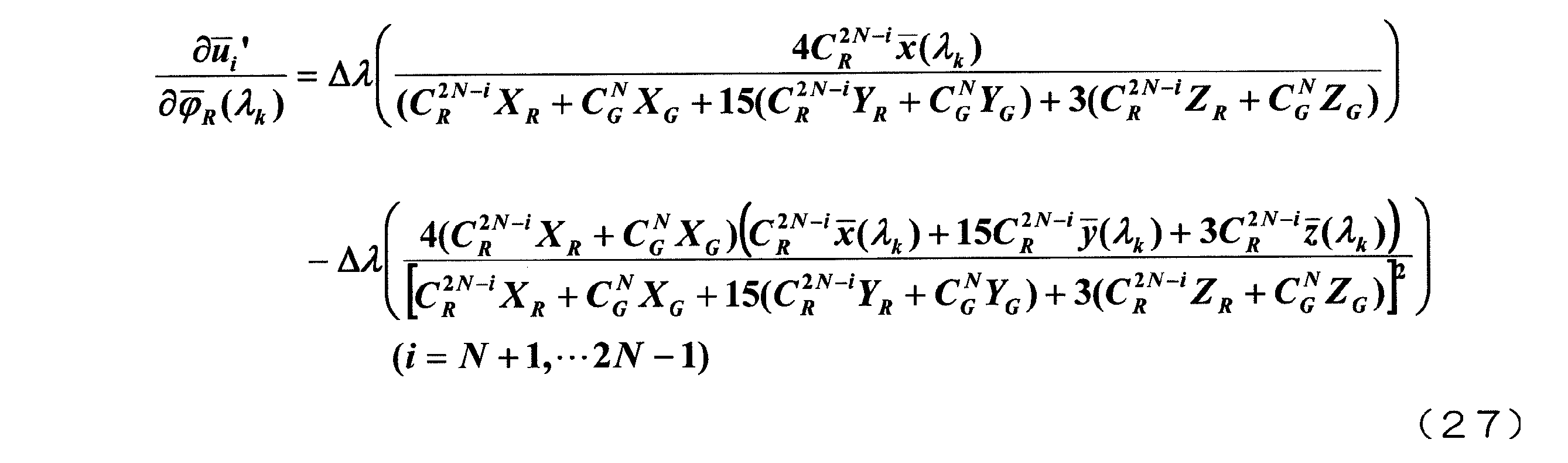
また、φ―
G(λk)に関する偏微分も同様に表すことができる。さらに、∂v―'/∂φ―(λk)についても、式(14)を用いて式(26)および(27)と同様な式を得ることができる。
δφ―
R(λ)およびδφ―
G(λ)を解とする連立方程式である式(25)を解くためには、例えば、連立方程式のLU分解法を用いることができる。また、連立方程式から求められたφ―
R(λ)+δφ―
R(λ)およびφ―
G(λ)+δφ―
G(λ)を新たな光学スペクトルとして、第2の計算を繰り返すと、計算によって得られる光学スペクトルを、目標である(つまり最適な)光学スペクトルに到達させることができる。これは、得られた光学スペクトルから計算される色度座標が、図5中に矢印で示しているように、目標の色度座標となることを意味する。
上述したような、2色の輝度および色度座標と光学スペクトルとの関係(2色についてのスペクトル決定アルゴリズム)を用いて、3つ以上の原色を用いて表示を行う表示装置の光学スペクトルを設計するためには、下記(I)および(II)の2通りの方法がある。
(I)2色についてのスペクトル決定アルゴリズムを2つの原色の組み合わせに順次適用する。赤、緑および青の3色を用いてカラー表示を行う表示装置の場合、例えば、光学スペクトルの計算をまず赤および緑の組み合わせについて行い、次に緑および青の組み合わせについて行い、その後青および赤の組み合わせについて行えばよい。同様に、赤、黄、緑および青の4色を用いてカラー表示を行う表示装置の場合、例えば、光学スペクトルの計算をまず赤および黄の組み合わせについて行い、次に黄および緑の組み合わせについて行い、続いて緑および青の組み合わせについて行い、最後に青および赤の組み合わせについて行えばよい。
(II)2色についてのスペクトル決定アルゴリズムを3つ以上のすべての原色の組み合わせに拡張して適用する。例えば、赤、緑および青の3色を用いてカラー表示を行う表示装置の場合、光学スペクトルの計算を赤、緑および青の組み合わせについて同時に行う。同様に、赤、黄、緑および青の4色を用いてカラー表示を行う表示装置の場合、光学スペクトルの計算を赤、黄、緑および青の組み合わせについて同時に行う。
以下、赤、黄、緑および青の4つの原色を用いてカラー表示を行う場合を例として、方法(II)を具体的に説明する。
目標とする輝度および色度座標を、赤単色、黄単色、緑単色および青単色についてそれぞれ(YR, uR', vR')、(YYe, uYe', vYe')、(YG, uG', vG')および(YB, uB', vB')とする。また、初期光学スペクトルとして、赤単色、黄単色、緑単色および青単色のスペクトルをそれぞれφ―
R(λ)、φ―
Ye(λ)、φ―
G(λ)およびφ―
B(λ)とする。
4色の場合における最適な光学スペクトルの設計も、2色の場合と同様に、多変数最適化問題として取り扱う。既に説明したように、多変数最適化問題では、変数と条件との個数が一致する必要がある。ここでは、変数は、赤単色、黄単色、緑単色および青単色の光学スペクトルφ―
R(λ)、φ―
Ye(λ)、φ―
G(λ)およびφ―
B(λ)である。また、条件は、色度座標(u', v')の値である。光学スペクトルの強度を変化させるパラメータを、赤単色、黄単色、緑単色および青単色のそれぞれについてCR、CYe、CGおよびCBとすると、スペクトル強度Cの条件は、4色の場合、下記式(28)で表されるように4(2N-1)個である。

u'およびv'の両方を条件に選ぶと、最適化問題の条件は8(2N-1)個となる。さらに、YR、YYe、YGおよびYBを条件に付け加えると、最適化問題の条件は4(4N-1)個となる。このため、赤単色、黄単色、緑単色および青単色の光学スペクトルのそれぞれに対して(4N-1)個の変数を設定することができる。なお、3色の場合も同様に、各原色の光学スペクトルに対して(4N-1)個の変数を設定することができる。
2色の場合についての式(25)を、4色に拡張すると、下記式(29)が得られる。

式(29)における添字kは1から(4N-1)までの値をとり、添字iは1から(2N-1)までの値をとる。従って、式(29)の左辺の行列式のサイズは4(4N-1)×4(4N-1)である(つまり左辺の行列式は4(4N-1)×4(4N-1)の行列要素を有する)が、式(25)について説明したのと同様の手法により、計算量を削減することができる。
δφ―
R(λ)、δφ―
Ye(λ)、δφ―
G(λ)およびδφ―
B(λ)を解とする連立方程式である式(29)を解くためには、例えば、連立方程式のLU分解法を用いることができる。また、連立方程式から求められたφ―
R(λ)+δφ―
R(λ)、φ―
Ye(λ)+δφ―
Ye(λ)、φ―
G(λ)+δφ―
G(λ)およびφ―
B(λ)+δφ―
B(λ)を新たな光学スペクトルとして、第2の計算を繰り返すと、計算によって得られる光学スペクトルを、目標である(つまり最適な)光学スペクトルに到達させることができる。これは、得られた光学スペクトルから計算される色度座標が、2色の場合について図5中に矢印で示しているように、目標の色度座標となることを意味する。
このように、方法(I)または(II)を用いることにより、3色以上の場合について最適な光学スペクトルの設計を行うことができる。そのため、3色の場合について例えば図6に示すような設計目標(この例では赤単色の輝度は25nit、緑単色の輝度は75nit、青単色の輝度は5nitである)が与えられたとすると、赤、緑および青の光学スペクトルとして図7に示すような光学スペクトルを最適なものとして設計することができる。従って、図8に矢印で示すように、表示装置の色再現範囲を、設計目標に近付けることができる。
また、光学スペクトルを決定する上記の方法によれば、白の色度を決定することもできる。以下、各原色の色度座標と白の色度座標との関係を、4色の場合を例として説明する。
赤単色、黄単色、緑単色および青単色の三刺激値をそれぞれ(XR, YR, ZR)、(XYe, YYe, ZYe)、(XG, YG, ZG)および(XB, YB, ZB)とする。また、それらの強度を0~1倍の間で変化させるパラメータを赤単色、黄単色、緑単色および青単色のそれぞれについてCR、CYe、CGおよびCBとする。このとき、白の色度座標(uW', vW')は、下記式(30)および(31)のように表すことができる。


なお、式(30)および(31)中におけるCWXW、CWYWおよびCWZWは、下記式(32)、(33)および(34)で表される。



式(30)および(31)中の(XR, ZR)、(XYe, ZYe)、(XG, ZG)および(XB, ZB)を消去すると、下記式(35)、(36)および(37)が得られる。



式(37)から、白の色度(uW', vW')は、各原色の色度(uC', vC')に対してCCYC/vC'の重み付け平均をしたものであることがわかる。このように、既に説明した光学スペクトルを決定する方法によれば、白の色度を決定することもできる。
ここまで、表示装置の光学スペクトルを設計する方法に存在する課題(i)~(iii)と、これらの課題から本願発明者が導き出した知見とを説明した。続いて、本発明の好適な実施形態における光学スペクトル設計方法を説明する。
本実施形態における光学スペクトル設計方法は、第1の色を表示する第1画素および第1の色とは異なる第2の色を表示する第2画素を含む複数の画素から構成されたカラー表示画素を有する表示装置の光学スペクトル設計方法である。表示装置は、例えば後述するような液晶表示装置であるが、勿論これに限定されるものではなく、本実施形態の光学スペクトル設計方法によれば、有機EL表示装置やプラズマディスプレイ等の種々の表示装置について、光学スペクトルの設計を行うことができる。
以下、図9を参照しながら、本実施形態における光学スペクトル設計方法を具体的に説明する。図9は、本実施形態における光学スペクトル設計方法のフローチャートである。
まず、第1の色についての目標とする輝度および色度座標(以下ではそれぞれ「第1目標輝度」および「第1目標色度座標」と呼ぶ)と、第2の色についての目標とする輝度および色度座標(以下ではそれぞれ「第2目標輝度」および「第2目標色度座標」と呼ぶ)とを設定する(工程S1)。
その後、設定された第1目標輝度、第1目標色度座標、第2目標輝度および第2目標色度座標に基づいて、光学スペクトルに関する計算を行う(工程S2)。この工程S2においては、設定された上述の輝度および色度座標だけでなく、第1目標色度座標および第2目標色度座標を結ぶ直線(便宜上「第1の直線」と呼ぶ)上に位置する複数の点の色度座標にも基づいて計算が行われる。工程S2は、式(13)~(27)を参照しながら既に説明した手法に相当し、例えば第1の色が赤で第2の色が緑である場合には、式(13)~(27)を用いた計算が行われ、それによって光学スペクトルが決定される。
図10を参照しながら、工程S2をより具体的に説明する。図10は、工程S2をより具体的に示すフローチャートである。
工程S1の後、まず、第1目標輝度、第1目標色度座標、第2目標輝度および第2目標色度座標に基づいて、第1の直線上に位置する複数の点の色度座標を計算する(工程S2A)。この工程S2Aは、例えば式(15)を用いて行うことができる(既に説明した「第1の計算」に相当)。
次に、第1の色に対応する第1スペクトルおよび第2の色に対応する第2スペクトルとして任意のスペクトルを仮定し、仮定された任意のスペクトルに基づいて、第1の直線上に位置する複数の点の色度座標を計算する(工程S2B)。この工程S2Bは、例えば式(20)を用いて行うことができる(既に説明した「第2の計算」に相当)。
その後、工程S2Aによって計算された色度座標および工程S2Bによって計算された色度座標を用いて計算を行う(工程S2C)。この工程S2Cは、例えば式(25)で示されるような連立方程式を解くことに相当する。
なお、工程S2AおよびS2Bを実行する順序は、図10の例に限定されるものではない。工程S2Bを工程S2Aよりも前に実行してもよい。
また、工程S2Bにおいて、仮定された任意のスペクトルに基づいて、第1の直線上に位置する複数の点の色度座標に加え、第1の色の輝度および第2の色の輝度を計算することが好ましい。例えば式(2)から、第1の色の輝度および第2の色の輝度を計算することができる。工程S2Bにおいて第1の色の輝度および第2の色の輝度を計算しておき、工程S2Cにおいてそれらの輝度も用いて計算を行うことは、多変数最適化問題における条件数を増やすことに他ならない(連立方程式である式(25)における行列にY―
R、Y
― Gを含む要素が存在していることに注目されたい)。
― Gを含む要素が存在していることに注目されたい)。
典型的には、表示装置のカラー表示画素を構成する複数の画素は、第1の色および第2の色とは異なる第3の色を表示する第3画素をさらに含む。カラー表示画素を構成する複数の画素は、例えば、赤を表示する赤画素、緑を表示する緑画素および青を表示する青画素を含む。
ここで、図11を参照しながら、カラー表示画素が3つの画素(第1画素、第2画素および第3画素)から構成されている場合(つまり3色の場合)について、光学スペクトルの設計方法を説明する。図11は、3色の場合の光学スペクトル設計方法のフローチャートである。
まず、図9に示したフローチャートと同様に、工程S1およびS2を行う。工程S2は、図10に示した工程S2A、S2BおよびS2Cを含んでもよい。
次に、第3の色についての目標とする輝度および色度座標(以下ではそれぞれ「第3目標輝度」および「第3目標色度座標」と呼ぶ)を設定する(工程S3)。
続いて、第2目標輝度、第2目標色度座標、第3目標輝度および第3目標色度座標と、第2目標色度座標および第3目標色度座標を結ぶ直線(便宜上「第2の直線」と呼ぶ)上に位置する複数の点の色度座標とに基づいて、光学スペクトルに関するさらなる計算を行う(工程S4)。
その後、第3目標輝度、第3目標色度座標、第1目標輝度および第1目標色度座標と、第3目標色度座標および第1目標色度座標を結ぶ直線(便宜上「第3の直線」と呼ぶ)上に位置する複数の点の色度座標とに基づいて、光学スペクトルに関するさらなる計算を行う(工程S5)。
図12を参照しながら、工程S4をより具体的に説明する。図12は、工程S4をより具体的に示すフローチャートである。
工程S3の後、まず、第2目標輝度、第2目標色度座標、第3目標輝度および第3目標色度座標に基づいて、第2の直線上に位置する複数の点の色度座標を計算する(工程S4A)。
次に、第2の色に対応する第2スペクトルおよび第3の色に対応する第3スペクトルとして任意のスペクトルを仮定し、仮定された任意のスペクトルに基づいて、第2の直線上に位置する複数の点の色度座標を計算する(工程S4B)。
その後、工程S4Aによって計算された色度座標および工程S4Bによって計算された色度座標を用いて計算を行う(工程S4C)。
なお、工程S4AおよびS4Bを実行する順序は、図12の例に限定されるものではない。工程S4Bを工程S4Aよりも前に実行してもよい。
また、工程S4Bにおいて、仮定された任意のスペクトルに基づいて、第2の直線上に位置する複数の点の色度座標に加え、第2の色の輝度および第3の色の輝度を計算することが好ましい。工程S4Bにおいて第2の色の輝度および第3の色の輝度を計算しておき、工程S4Cにおいてそれらの輝度も用いて計算を行うことは、多変数最適化問題における条件数を増やすことに他ならないからである。
図13を参照しながら、工程S5をより具体的に説明する。図13は、工程S5をより具体的に示すフローチャートである。
工程S4の後、まず、第3目標輝度、第3目標色度座標、第1目標輝度および第1目標色度座標に基づいて、第3の直線上に位置する複数の点の色度座標を計算する(工程S5A)。
次に、第3の色に対応する第3スペクトルおよび第1の色に対応する第1スペクトルとして任意のスペクトルを仮定し、仮定された任意のスペクトルに基づいて、第3の直線上に位置する複数の点の色度座標を計算する(工程S5B)。
その後、工程S5Aによって計算された色度座標および工程S5Bによって計算された色度座標を用いて計算を行う(工程S5C)。
なお、工程S5AおよびS5Bを実行する順序は、図13の例に限定されるものではない。工程S5Bを工程S5Aよりも前に実行してもよい。
また、工程S5Bにおいて、仮定された任意のスペクトルに基づいて、第3の直線上に位置する複数の点の色度座標に加え、第3の色の輝度および第1の色の輝度を計算することが好ましい。工程S5Bにおいて第3の色の輝度および第1の色の輝度を計算しておき、工程S5Cにおいてそれらの輝度も用いて計算を行うことは、多変数最適化問題における条件数を増やすことに他ならないからである。
なお、図11、図12および図13を参照しながら説明した光学スペクトル設計方法は、2色についてのスペクトル決定アルゴリズムを2つの原色の組み合わせに順次適用する方法である(既に説明した方法(I)に相当する)。勿論、2色についてのスペクトル決定アルゴリズムを3つの原色の組み合わせに拡張して適用する光学スペクトル設計方法を採用してもよい(既に説明した方法(II)に相当する)。以下、図14を参照しながら、そのような光学スペクトル設計方法を説明する。
まず、第1目標輝度、第1目標色度座標、第2目標輝度、第2目標色度座標、第3目標輝度および第3目標色度座標を設定する(工程S11)。
その後、設定された第1目標輝度、第1目標色度座標、第2目標輝度、第2目標色度座標、第3目標輝度および第3目標色度座標に基づいて、光学スペクトルに関する計算を行う(工程S12)。この工程S12においては、設定された上述の輝度および色度座標だけでなく、第1の直線上に位置する複数の点の色度座標と、第2の直線上に位置する複数の点の色度座標と、第3の直線上に位置する複数の点の色度座標とにも基づいて、計算が行われる。
図15を参照しながら、工程S12をより具体的に説明する。図15は、工程S12をより具体的に示すフローチャートである。
工程S11の後、まず、第1目標輝度、第1目標色度座標、第2目標輝度、第2目標色度座標、第3目標輝度および第3目標色度座標に基づいて、第1の直線上に位置する複数の点の色度座標、第2の直線上に位置する複数の点の色度座標および第3の直線上に位置する複数の点の色度座標を計算する(工程S12A)。
次に、第1の色に対応する第1スペクトル、第2の色に対応する第2スペクトルおよび第3の色に対応する第3スペクトルとして任意のスペクトルを仮定し、仮定された任意のスペクトルに基づいて、第1の直線上に位置する複数の点の色度座標、第2の直線上に位置する複数の点の色度座標および第3の直線上に位置する複数の点の色度座標を計算する(工程S12B)。
その後、工程S12Aによって計算された色度座標および工程S12Bによって計算された色度座標を用いて計算を行う(工程S12C)。
なお、工程S12AおよびS12Bを実行する順序は、図15の例に限定されるものではない。工程S12Bを工程S12Aよりも前に実行してもよい。
また、工程S12Bにおいて、仮定された任意のスペクトルに基づいて、第1、第2および第3の直線上に位置する複数の点の色度座標に加え、第1の色の輝度、第2の色の輝度および第3の色の輝度を計算することが好ましい。工程S12Bにおいて第1の色の輝度、第2の色の輝度および第3の色の輝度を計算しておき、工程S12Cにおいてそれらの輝度も用いて計算を行うことは、多変数最適化問題における条件数を増やすことに他ならないからである。
なお、表示装置のカラー表示画素を構成する複数の画素は、第1の色、第2の色および第3の色とは異なる第4の色を表示する第4画素をさらに含んでもよい。つまり、表示装置は、多原色表示装置であってもよい。多原色表示装置のカラー表示画素を構成する複数の画素は、例えば、赤画素、緑画素および青画素に加えて、黄を表示する黄画素を含む。勿論、カラー表示画素を構成する複数の画素は、黄画素に代えて、シアンを表示するシアン画素や、マゼンタを表示するマゼンタ画素を含んでもよい。
ここで、図16を参照しながら、カラー表示画素が4つの画素(第1画素、第2画素、第3画素および第4画素)から構成されている場合(つまり4色の場合)について、光学スペクトルの設計方法を説明する。図16は、4色の場合の光学スペクトル設計方法のフローチャートである。
まず、図11に示したフローチャートと同様に、工程S1、S2、S3およびS4を行う。工程S2は、図10に示した工程S2A、S2BおよびS2Cを含んでもよいし、工程S4は、図12に示した工程S4A、S4BおよびS4Cを含んでもよい。
次に、第4の色についての目標とする輝度および色度座標(以下ではそれぞれ「第4目標輝度」および「第4目標色度座標」と呼ぶ)を設定する(工程S6)。
続いて、第3目標輝度、第3目標色度座標、第4目標輝度および第4目標色度座標と、第3目標色度座標および第4目標色度座標を結ぶ直線(便宜上「第3の直線」と呼ぶ)上に位置する複数の点の色度座標とに基づいて、光学スペクトルに関するさらなる計算を行う(工程S7)。
その後、第4目標輝度、第4目標色度座標、第1目標輝度および第1目標色度座標と、第4目標色度座標および第1目標色度座標を結ぶ直線(便宜上「第4の直線」と呼ぶ)上に位置する複数の点の色度座標とに基づいて、光学スペクトルに関するさらなる計算を行う(工程S8)。
図17を参照しながら、工程S7をより具体的に説明する。図17は、工程S7をより具体的に示すフローチャートである。
工程S6の後、まず、第3目標輝度、第3目標色度座標、第4目標輝度および第4目標色度座標に基づいて、第3の直線上に位置する複数の点の色度座標を計算する(工程S7A)。
次に、第3の色に対応する第3スペクトルおよび第4の色に対応する第4スペクトルとして任意のスペクトルを仮定し、仮定された任意のスペクトルに基づいて、第3の直線上に位置する複数の点の色度座標を計算する(工程S7B)。
その後、工程S7Aによって計算された色度座標および工程S7Bによって計算された色度座標を用いて計算を行う(工程S7C)。
なお、工程S7AおよびS7Bを実行する順序は、図17の例に限定されるものではない。工程S7Bを工程S7Aよりも前に実行してもよい。
また、工程S7Bにおいて、仮定された任意のスペクトルに基づいて、第3の直線上に位置する複数の点の色度座標に加え、第3の色の輝度および第4の色の輝度を計算することが好ましい。工程S7Bにおいて第3の色の輝度および第4の色の輝度を計算しておき、工程S7Cにおいてそれらの輝度も用いて計算を行うことは、多変数最適化問題における条件数を増やすことに他ならないからである。
図18を参照しながら、工程S8をより具体的に説明する。図18は、工程S8をより具体的に示すフローチャートである。
工程S7の後、まず、第4目標輝度、第4目標色度座標、第1目標輝度および第1目標色度座標に基づいて、第4の直線上に位置する複数の点の色度座標を計算する(工程S8A)。
次に、第4の色に対応する第4スペクトルおよび第1の色に対応する第1スペクトルとして任意のスペクトルを仮定し、仮定された任意のスペクトルに基づいて、第4の直線上に位置する複数の点の色度座標を計算する(工程S8B)。
その後、工程S8Aによって計算された色度座標および工程S8Bによって計算された色度座標を用いて計算を行う(工程S8C)。
なお、工程S8AおよびS8Bを実行する順序は、図18の例に限定されるものではない。工程S8Bを工程S8Aよりも前に実行してもよい。
また、工程S8Bにおいて、仮定された任意のスペクトルに基づいて、第4の直線上に位置する複数の点の色度座標に加え、第4の色の輝度および第1の色の輝度を計算することが好ましい。工程S8Bにおいて第4の色の輝度および第1の色の輝度を計算しておき、工程S8Cにおいてそれらの輝度も用いて計算を行うことは、多変数最適化問題における条件数を増やすことに他ならないからである。
なお、図16、図17および図18を参照しながら説明した光学スペクトル設計方法は、2色についてのスペクトル決定アルゴリズムを2つの原色の組み合わせに順次適用する方法である(既に説明した方法(I)に相当する)。勿論、2色についてのスペクトル決定アルゴリズムを3つの原色の組み合わせに拡張して適用する光学スペクトル設計方法を採用してもよい(既に説明した方法(II)に相当する)。以下、図19を参照しながら、4色の場合についてそのような光学スペクトル設計方法を説明する。
まず、第1目標輝度、第1目標色度座標、第2目標輝度、第2目標色度座標、第3目標輝度、第3目標色度座標、第4目標輝度および第4目標色度座標を設定する(工程S21)、その後、設定された第1目標輝度、第1目標色度座標、第2目標輝度、第2目標色度座標、第3目標輝度、第3目標色度座標、第4目標輝度および第4目標色度座標に基づいて、光学スペクトルに関する計算を行う(工程S22)。この工程S22においては、設定された上述の輝度および色度座標だけでなく、第1の直線上に位置する複数の点の色度座標と、第2の直線上に位置する複数の点の色度座標と、第3の直線上に位置する複数の点の色度座標と、第4の直線上に位置する複数の点の色度座標とにも基づいて、計算が行われる。工程S22は、式(28)および(29)を参照しながら既に説明した手法に相当し、例えば第1の色が赤、第2の色が黄、第3の色が緑、第4の色が青である場合には、式(28)および(29)を用いた計算が行われ、それによって光学スペクトルが決定される。
図20を参照しながら、工程S22をより具体的に説明する。図20は、工程S22をより具体的に示すフローチャートである。
工程S21の後、まず、第1目標輝度、第1目標色度座標、第2目標輝度、第2目標色度座標、第3目標輝度、第3目標色度座標、第4目標輝度および第4目標色度座標に基づいて、第1の直線上に位置する複数の点の色度座標、第2の直線上に位置する複数の点の色度座標、第3の直線上に位置する複数の点の色度座標および第4の直線上に位置する複数の点の色度座標を計算する(工程S22A)。
次に、第1の色に対応する第1スペクトル、第2の色に対応する第2スペクトル、第3の色に対応する第3スペクトルおよび第4の色に対応する第4スペクトルとして任意のスペクトルを仮定し、仮定された任意のスペクトルに基づいて、第1の直線上に位置する複数の点の色度座標、第2の直線上に位置する複数の点の色度座標、第3の直線上に位置する複数の点の色度座標および第4の直線上に位置する複数の点の色度座標を計算する(工程S22B)。
その後、工程S22Aによって計算された色度座標および工程S22Bによって計算された色度座標を用いて計算を行う(工程S22C)。この工程S22Cは、例えば式(29)で示されるような連立方程式を解くことに相当する。
なお、工程S22AおよびS22Bを実行する順序は、図20の例に限定されるものではない。工程S22Bを工程S22Aよりも前に実行してもよい。
また、工程S22Bにおいて、仮定された任意のスペクトルに基づいて、第1、第2、第3および第4の直線上に位置する複数の点の色度座標に加え、第1の色の輝度、第2の色の輝度、第3の色の輝度および第4の色の輝度を計算することが好ましい。工程S22Bにおいて第1の色の輝度、第2の色の輝度、第3の色の輝度および第4の輝度を計算しておき、工程S22Cにおいてそれらの輝度も用いて計算を行うことは、多変数最適化問題における条件数を増やすことに他ならないからである。
上述したように、本実施形態における光学スペクトル設計方法によれば、2色の目標色度座標同士を結ぶ直線上に位置する複数の点の色度座標を条件として用いることにより、目標とする輝度および色度に対して最適な光学スペクトルを設計することができる。本実施形態における光学スペクトル設計方法は、カットアンドトライにより光学スペクトルを決定する手法に比べ、設定目標に対して精度が高く、且つ、効率的な光学スペクトルの設計が可能である。
また、本実施形態における光学スペクトル設計方法は、設計した光学スペクトルが最適化されたものであるか否かを判定するための判定工程を含むことがさらに好ましい。図21に、4色の場合について判定工程を含むフローチャートを示す。
図21に示す例では、まず、図19に示したフローチャートと同様に、工程S21およびS22を行う。その後、工程S22によって計算された光学スペクトルについて所定の二次形式の関数を設定し、光学スペクトルに一定の変分値を加えたときに二次形式の関数が対称な二次関数になっているか否かを判定する(工程S23)。この工程S23は、式(7)~(12)を参照しながら既に説明した手法に相当する。
光学スペクトル設計方法がこのような判定工程(工程S23)を含むことにより、目標とする輝度および色度に最適な光学スペクトルが設計できているか、確認することができるので、より精度の高い設計が可能となる。
なお、ここまでは、カラー表示画素が3つの画素から構成される場合(3色構成)および4つの画素から構成される場合(4色構成)を例として説明を行ったが、本発明はこれに限定されるものではない。カラー表示画素が5つ以上の画素から構成される場合であっても、同様の方法により光学スペクトルの設計を行うことができる。
本実施形態における光学スペクトル設計方法は、表示装置の製造方法における1工程として好適に実行され得る。この場合、表示装置の製造方法は、本実施形態における光学スペクトル設計方法により光学スペクトルを設計する工程と、設計された光学スペクトルを有する表示装置を作製する工程とを含む。後者の工程において作製される表示装置が、液晶表示装置である場合、この工程は、典型的には、設計された光学スペクトルが実現されるように照明素子(バックライト)およびカラーフィルタを用意する工程を含む。
本発明によると、目標とする輝度および色度に対して最適な光学スペクトルを設計することができる表示装置の光学スペクトル設計方法が提供される。本発明による表示装置の光学スペクトル設計方法は、液晶表示装置をはじめとする種々の表示装置の光学スペクトルの設計に好適に用いられ、4つ以上の原色を用いてカラー表示を行う多原色表示装置の光学スペクトルの設計も好適に行うことができる。
Claims (25)
- 第1の色を表示する第1画素および前記第1の色とは異なる第2の色を表示する第2画素を含む複数の画素から構成されたカラー表示画素を有する表示装置の光学スペクトル設計方法であって、
前記第1の色についての目標とする輝度および色度座標である第1目標輝度および第1目標色度座標と、前記第2の色についての目標とする輝度および色度座標である第2目標輝度および第2目標色度座標とを設定する工程(a)と、
少なくとも前記第1目標輝度、前記第1目標色度座標、前記第2目標輝度および前記第2目標色度座標と、前記第1目標色度座標および前記第2目標色度座標を結ぶ第1の直線上に位置する複数の点の色度座標とに基づいて、光学スペクトルに関する計算を行う工程(b)と、
を包含する表示装置の光学スペクトル設計方法。 - 前記工程(b)は、
前記第1目標輝度、前記第1目標色度座標、前記第2目標輝度および前記第2目標色度座標に基づいて、前記第1の直線上に位置する前記複数の点の色度座標を計算する工程(b1)と、
前記第1の色に対応する第1スペクトルおよび前記第2の色に対応する第2スペクトルとして任意のスペクトルを仮定し、仮定された前記任意のスペクトルに基づいて、前記第1の直線上に位置する前記複数の点の色度座標を計算する工程(b2)と、
前記工程(b1)によって計算された色度座標および前記工程(b2)によって計算された色度座標を用いて計算を行う工程(b3)と、
を含む請求項1に記載の表示装置の光学スペクトル設計方法。 - 前記工程(b2)において、仮定された前記任意のスペクトルに基づいて、前記第1の色の輝度および前記第2の色の輝度も計算され、
前記工程(b3)において、前記工程(b2)によって計算された前記第1の色の輝度および前記第2の色の輝度も用いて計算が行われる請求項2に記載の表示装置の光学スペクトル設計方法。 - 前記複数の画素は、前記第1の色および前記第2の色とは異なる第3の色を表示する第3画素をさらに含む請求項1から3のいずれかに記載の表示装置の光学スペクトル設計方法。
- 前記第3の色についての目標とする輝度および色度座標である第3目標輝度および第3目標色度座標を設定する工程(c)と、
少なくとも前記第2目標輝度、前記第2目標色度座標、前記第3目標輝度および前記第3目標色度座標と、前記第2目標色度座標および前記第3目標色度座標を結ぶ第2の直線上に位置する複数の点の色度座標とに基づいて、光学スペクトルに関するさらなる計算を行う工程(d)と、をさらに包含する請求項4に記載の表示装置の光学スペクトル設計方法。 - 前記工程(d)は、
前記第2目標輝度、前記第2目標色度座標、前記第3目標輝度および前記第3目標色度座標に基づいて、前記第2の直線上に位置する前記複数の点の色度座標を計算する工程(d1)と、
前記第2の色に対応する第2スペクトルおよび前記第3の色に対応する第3スペクトルとして任意のスペクトルを仮定し、仮定された前記任意のスペクトルに基づいて、前記第2の直線上に位置する前記複数の点の色度座標を計算する工程(d2)と、
前記工程(d1)によって計算された色度座標および前記工程(d2)によって計算された色度座標を用いて計算を行う工程(d3)と、
を含む請求項5に記載の表示装置の光学スペクトル設計方法。 - 前記工程(d2)において、仮定された前記任意のスペクトルに基づいて、前記第2の色の輝度および前記第3の色の輝度も計算され、
前記工程(d3)において、前記工程(d2)によって計算された前記第2の色の輝度および前記第3の色の輝度も用いて計算が行われる請求項6に記載の表示装置の光学スペクトル設計方法。 - 前記工程(d)の後、前記第3目標輝度、前記第3目標色度座標、前記第1目標輝度および前記第1目標色度座標と、前記第3目標色度座標および前記第1目標色度座標を結ぶ第3の直線上に位置する複数の点の色度座標とに基づいて、光学スペクトルに関するさらなる計算を行う工程(e)をさらに包含する請求項5から7のいずれかに記載の表示装置の光学スペクトル設計方法。
- 前記複数の画素は、前記第1の色および前記第2の色とは異なる第3の色を表示する第3画素をさらに含み、
前記工程(a)において、前記第3の色についての目標とする輝度および色度座標である第3目標輝度および第3目標色度座標も設定され、
前記工程(b)において、前記第3目標輝度および前記第3目標色度座標と、前記第2目標色度座標および前記第3目標色度座標を結ぶ第2の直線上に位置する複数の点の色度座標と、前記第3目標色度座標および前記第1目標色度座標を結ぶ第3の直線上に位置する複数の点の色度座標とにも基づいて、計算が行われる請求項1に記載の表示装置の光学スペクトル設計方法。 - 前記工程(b)は、
前記第1目標輝度、前記第1目標色度座標、前記第2目標輝度、前記第2目標色度座標、前記第3目標輝度および前記第3目標色度座標に基づいて、前記第1の直線上に位置する前記複数の点の色度座標、前記第2の直線上に位置する前記複数の点の色度座標および前記第3の直線上に位置する前記複数の点の色度座標を計算する工程(b1)と、
前記第1の色に対応する第1スペクトル、前記第2の色に対応する第2スペクトルおよび前記第3の色に対応する第3スペクトルとして任意のスペクトルを仮定し、仮定された前記任意のスペクトルに基づいて、前記第1の直線上に位置する前記複数の点の色度座標、前記第2の直線上に位置する前記複数の点の色度座標および前記第3の直線上に位置する前記複数の点の色度座標を計算する工程(b2)と、
前記工程(b1)によって計算された色度座標および前記工程(b2)によって計算された色度座標を用いて計算を行う工程(b3)と、
を含む請求項9に記載の表示装置の光学スペクトル設計方法。 - 前記工程(b2)において、仮定された前記任意のスペクトルに基づいて、前記第1の色の輝度、前記第2の色の輝度および前記第3の色の輝度も計算され、
前記工程(b3)において、前記工程(b2)によって計算された前記第1の色の輝度、前記第2の色の輝度および前記第3の色の輝度も用いて計算が行われる請求項10に記載の表示装置の光学スペクトル設計方法。 - 前記複数の画素は、前記第1の色、前記第2の色および前記第3の色とは異なる第4の色を表示する第4画素をさらに含む請求項4から7のいずれかに記載の表示装置の光学スペクトル設計方法。
- 前記第4の色についての目標とする輝度および色度座標である第4目標輝度および第4目標色度座標を設定する工程(f)と、
前記第3目標輝度、前記第3目標色度座標、前記第4目標輝度および前記第4目標色度座標と、前記第3目標色度座標および前記第4目標色度座標を結ぶ第3の直線上に位置する複数の点の色度座標とに基づいて、光学スペクトルに関するさらなる計算を行う工程(g)と、をさらに包含する請求項12に記載の表示装置の光学スペクトル設計方法。 - 前記工程(g)は、
前記第3目標輝度、前記第3目標色度座標、前記第4目標輝度および前記第4目標色度座標に基づいて、前記第3の直線上に位置する前記複数の点の色度座標を計算する工程(g1)と、
前記第3の色に対応する第3スペクトルおよび前記第4の色に対応する第4スペクトルとして任意のスペクトルを仮定し、仮定された前記任意のスペクトルに基づいて、前記第3の直線上に位置する前記複数の点の色度座標を計算する工程(g2)と、
前記工程(g1)によって計算された色度座標および前記工程(g2)によって計算された色度座標を用いて計算を行う工程(g3)と、
を含む請求項13に記載の表示装置の光学スペクトル設計方法。 - 前記工程(g2)において、仮定された前記任意のスペクトルに基づいて、前記第3の色の輝度および前記第4の色の輝度も計算され、
前記工程(g3)において、前記工程(g2)によって計算された前記第3の色の輝度および前記第4の色の輝度も用いて計算が行われる請求項14に記載の表示装置の光学スペクトル設計方法。 - 前記工程(g)の後、前記第4目標輝度、前記第4目標色度座標、前記第1目標輝度および前記第1目標色度座標と、前記第4目標色度座標および前記第1目標色度座標を結ぶ第4の直線上に位置する複数の点の色度座標とに基づいて、光学スペクトルに関するさらなる計算を行う工程(h)をさらに包含する請求項13から15のいずれかに記載の表示装置の光学スペクトル設計方法。
- 前記複数の画素は、前記第1の色および前記第2の色とは異なる第3の色を表示する第3画素と、前記第1の色、前記第2の色および前記第3の色とは異なる第4の色を表示する第4画素とをさらに含み、
前記工程(a)において、前記第3の色についての目標とする輝度および色度座標である第3目標輝度および第3目標色度座標と、前記第4の色についての目標とする輝度および色度座標である第4目標輝度および第4目標色度座標も設定され、
前記工程(b)において、前記第3目標輝度、前記第3目標色度座標、前記第4目標輝度および前記第4目標色度座標と、前記第2目標色度座標および前記第3目標色度座標を結ぶ第2の直線上に位置する複数の点の色度座標と、前記第3目標色度座標および前記第4目標色度座標を結ぶ第3の直線上に位置する複数の点の色度座標と、前記第4目標色度座標および前記第1目標色度座標を結ぶ第4の直線上に位置する複数の点の色度座標とにも基づいて、計算が行われる請求項1に記載の表示装置の光学スペクトル設計方法。 - 前記工程(b)は、
前記第1目標輝度、前記第1目標色度座標、前記第2目標輝度、前記第2目標色度座標、前記第3目標輝度、前記第3目標色度座標、前記第4目標輝度および前記第4目標色度座標に基づいて、前記第1の直線上に位置する前記複数の点の色度座標、前記第2の直線上に位置する前記複数の点の色度座標、前記第3の直線上に位置する前記複数の点の色度座標および前記第4の直線上に位置する前記複数の点の色度座標を計算する工程(b1)と、
前記第1の色に対応する第1スペクトル、前記第2の色に対応する第2スペクトル、前記第3の色に対応する第3スペクトルおよび前記第4の色に対応する第4スペクトルとして任意のスペクトルを仮定し、仮定された前記任意のスペクトルに基づいて、前記第1の直線上に位置する前記複数の点の色度座標、前記第2の直線上に位置する前記複数の点の色度座標、前記第3の直線上に位置する前記複数の点の色度座標および前記第4の直線上に位置する前記複数の点の色度座標を計算する工程(b2)と、
前記工程(b1)によって計算された色度座標および前記工程(b2)によって計算された色度座標を用いて計算を行う工程(b3)と、
を含む請求項17に記載の表示装置の光学スペクトル設計方法。 - 前記工程(b2)において、仮定された前記任意のスペクトルに基づいて、前記第1の色の輝度、前記第2の色の輝度、前記第3の色の輝度および前記第4の色の輝度も計算され、
前記工程(b3)において、前記工程(b2)によって計算された前記第1の色の輝度、前記第2の色の輝度、前記第3の色の輝度および前記第4の色の輝度も用いて計算が行われる請求項18に記載の表示装置の光学スペクトル設計方法。 - 前記工程(b)によって計算された光学スペクトルについて所定の二次形式の関数を設定し、前記光学スペクトルに一定の変分値を加えたときに前記二次形式の関数が対称な二次関数になっているか否かを判定する工程(i)をさらに包含する請求項1から19のいずれかに記載の表示装置の光学スペクトル設計方法。
- 前記複数の画素は、赤を表示する赤画素、緑を表示する緑画素および青を表示する青画素を含む請求項1から20のいずれかに記載の表示装置の光学スペクトル設計方法。
- 前記複数の画素は、黄を表示する黄画素をさらに含む請求項21に記載の表示装置の光学スペクトル設計方法。
- 請求項1から22のいずれかに記載の表示装置の光学スペクトル設計方法により光学スペクトルを設計する工程(A)と、
設計された前記光学スペクトルを有する表示装置を作製する工程(B)と、
を包含する表示装置の製造方法。 - 前記工程(B)において作製される前記表示装置は、液晶表示装置である請求項23に記載の表示装置の製造方法。
- 前記液晶表示装置は、照明素子と、カラーフィルタとを含み、
前記工程(B)は、前記光学スペクトルが実現されるように前記照明素子および前記カラーフィルタを用意する工程(B1)を含む請求項24に記載の表示装置の製造方法。
Applications Claiming Priority (2)
| Application Number | Priority Date | Filing Date | Title |
|---|---|---|---|
| JP2011036516 | 2011-02-23 | ||
| JP2011-036516 | 2011-02-23 |
Publications (1)
| Publication Number | Publication Date |
|---|---|
| WO2012115041A1 true WO2012115041A1 (ja) | 2012-08-30 |
Family
ID=46720818
Family Applications (1)
| Application Number | Title | Priority Date | Filing Date |
|---|---|---|---|
| PCT/JP2012/053979 Ceased WO2012115041A1 (ja) | 2011-02-23 | 2012-02-20 | 表示装置の光学スペクトル設計方法および表示装置の製造方法 |
Country Status (1)
| Country | Link |
|---|---|
| WO (1) | WO2012115041A1 (ja) |
Cited By (1)
| Publication number | Priority date | Publication date | Assignee | Title |
|---|---|---|---|---|
| CN108154540A (zh) * | 2017-12-22 | 2018-06-12 | 武汉华显光电技术有限公司 | 最佳色度和亮度确定方法、装置及计算机可读存储介质 |
Citations (5)
| Publication number | Priority date | Publication date | Assignee | Title |
|---|---|---|---|---|
| JP2002164172A (ja) * | 2000-11-27 | 2002-06-07 | Idemitsu Kosan Co Ltd | 表示素子のシミュレーション方法 |
| JP2005129040A (ja) * | 2003-10-01 | 2005-05-19 | Toray Ind Inc | 液晶表示装置用カラーフィルター設計システム |
| JP2005189402A (ja) * | 2003-12-25 | 2005-07-14 | Sony Corp | カラーフィルタ、カラーフィルタの製造方法および表示装置 |
| JP2009020115A (ja) * | 2000-12-06 | 2009-01-29 | Honeywell Internatl Inc | 蛍光体の適切な混合を求めるための方法 |
| WO2010091539A1 (zh) * | 2009-02-10 | 2010-08-19 | 致茂电子股份有限公司 | 光源测量方法及光源测量系统 |
-
2012
- 2012-02-20 WO PCT/JP2012/053979 patent/WO2012115041A1/ja not_active Ceased
Patent Citations (5)
| Publication number | Priority date | Publication date | Assignee | Title |
|---|---|---|---|---|
| JP2002164172A (ja) * | 2000-11-27 | 2002-06-07 | Idemitsu Kosan Co Ltd | 表示素子のシミュレーション方法 |
| JP2009020115A (ja) * | 2000-12-06 | 2009-01-29 | Honeywell Internatl Inc | 蛍光体の適切な混合を求めるための方法 |
| JP2005129040A (ja) * | 2003-10-01 | 2005-05-19 | Toray Ind Inc | 液晶表示装置用カラーフィルター設計システム |
| JP2005189402A (ja) * | 2003-12-25 | 2005-07-14 | Sony Corp | カラーフィルタ、カラーフィルタの製造方法および表示装置 |
| WO2010091539A1 (zh) * | 2009-02-10 | 2010-08-19 | 致茂电子股份有限公司 | 光源测量方法及光源测量系统 |
Cited By (1)
| Publication number | Priority date | Publication date | Assignee | Title |
|---|---|---|---|---|
| CN108154540A (zh) * | 2017-12-22 | 2018-06-12 | 武汉华显光电技术有限公司 | 最佳色度和亮度确定方法、装置及计算机可读存储介质 |
Similar Documents
| Publication | Publication Date | Title |
|---|---|---|
| CN101389999B (zh) | 液晶显示装置 | |
| CN103955079B (zh) | 利用rgb显示装置获取rgbw显示装置白色的亮度和色度的方法 | |
| JP4763078B2 (ja) | 表示装置 | |
| CN105118413B (zh) | 基于白色子像素色偏的rgbw的补偿方法及装置 | |
| CN102663975B (zh) | 显示装置 | |
| WO2011065332A1 (ja) | 多原色表示装置 | |
| US20160293080A1 (en) | Method of raising wrgb color saturation | |
| TWI463464B (zh) | 紅綠藍白光顯示系統之背光調整裝置及其方法 | |
| CN105934020A (zh) | 一种多色led匹配光谱和照度的方法 | |
| WO2012005170A1 (ja) | 多原色液晶表示装置 | |
| JP6238757B2 (ja) | ホワイトバランス調整方法、ホワイトバランス調整装置および表示装置 | |
| JP4364281B2 (ja) | 表示装置 | |
| JP2018508913A (ja) | 画像データ処理方法及び装置 | |
| US20100289814A1 (en) | Color transformation method and corresponding color display method | |
| CN101305408B (zh) | 处理驱动显示器的像素信号的方法和设备及应用的显示器 | |
| CN117195087A (zh) | 一种基于支持向量机的显示器光谱特征化方法 | |
| US8194979B2 (en) | Method of correcting false-color pixel in digital image | |
| WO2012115041A1 (ja) | 表示装置の光学スペクトル設計方法および表示装置の製造方法 | |
| WO2017118040A1 (zh) | 一种图像处理的方法及装置 | |
| CN102542998A (zh) | 伽玛校正方法 | |
| WO2015020137A1 (ja) | 表示装置 | |
| CN104504262B (zh) | 显示器滤色片透过率谱线分布优化方法 | |
| CN115938267B (zh) | 一种多基色系统基色参数优化方法 | |
| CN106887219B (zh) | 显示器画面生成方法及系统 | |
| CN109870844B (zh) | 一种基于补色光的节能显示方法 |
Legal Events
| Date | Code | Title | Description |
|---|---|---|---|
| 121 | Ep: the epo has been informed by wipo that ep was designated in this application |
Ref document number: 12749601 Country of ref document: EP Kind code of ref document: A1 |
|
| NENP | Non-entry into the national phase |
Ref country code: DE |
|
| 122 | Ep: pct application non-entry in european phase |
Ref document number: 12749601 Country of ref document: EP Kind code of ref document: A1 |
|
| NENP | Non-entry into the national phase |
Ref country code: JP |