WO2012114792A1 - 画像処理装置及び画像処理方法 - Google Patents
画像処理装置及び画像処理方法 Download PDFInfo
- Publication number
- WO2012114792A1 WO2012114792A1 PCT/JP2012/050928 JP2012050928W WO2012114792A1 WO 2012114792 A1 WO2012114792 A1 WO 2012114792A1 JP 2012050928 W JP2012050928 W JP 2012050928W WO 2012114792 A1 WO2012114792 A1 WO 2012114792A1
- Authority
- WO
- WIPO (PCT)
- Prior art keywords
- unit
- scan pattern
- quantization matrix
- scan
- image
- Prior art date
- Legal status (The legal status is an assumption and is not a legal conclusion. Google has not performed a legal analysis and makes no representation as to the accuracy of the status listed.)
- Ceased
Links
Images


Classifications
-
- H—ELECTRICITY
- H04—ELECTRIC COMMUNICATION TECHNIQUE
- H04N—PICTORIAL COMMUNICATION, e.g. TELEVISION
- H04N19/00—Methods or arrangements for coding, decoding, compressing or decompressing digital video signals
- H04N19/10—Methods or arrangements for coding, decoding, compressing or decompressing digital video signals using adaptive coding
- H04N19/102—Methods or arrangements for coding, decoding, compressing or decompressing digital video signals using adaptive coding characterised by the element, parameter or selection affected or controlled by the adaptive coding
- H04N19/124—Quantisation
- H04N19/126—Details of normalisation or weighting functions, e.g. normalisation matrices or variable uniform quantisers
-
- H—ELECTRICITY
- H04—ELECTRIC COMMUNICATION TECHNIQUE
- H04N—PICTORIAL COMMUNICATION, e.g. TELEVISION
- H04N19/00—Methods or arrangements for coding, decoding, compressing or decompressing digital video signals
- H04N19/46—Embedding additional information in the video signal during the compression process
- H04N19/463—Embedding additional information in the video signal during the compression process by compressing encoding parameters before transmission
-
- H—ELECTRICITY
- H04—ELECTRIC COMMUNICATION TECHNIQUE
- H04N—PICTORIAL COMMUNICATION, e.g. TELEVISION
- H04N19/00—Methods or arrangements for coding, decoding, compressing or decompressing digital video signals
- H04N19/60—Methods or arrangements for coding, decoding, compressing or decompressing digital video signals using transform coding
- H04N19/61—Methods or arrangements for coding, decoding, compressing or decompressing digital video signals using transform coding in combination with predictive coding
Definitions
- the present disclosure relates to an image processing apparatus and an image processing method.
- H. is one of the standard specifications for image coding.
- different quantization steps can be used for each component of orthogonal transform coefficients when image data is quantized.
- the quantization step for each component of the orthogonal transform coefficient can be set based on a quantization matrix (also referred to as a scaling list) defined with a size equivalent to the unit of the orthogonal transform and a reference step value.
- a user can use a predetermined quantization matrix prepared in advance for each combination of size, prediction method (intra prediction / inter prediction), and signal component (Y / Cb / Cr component).
- the user can also define a unique quantization matrix separately from the predetermined quantization matrix.
- the user-specific quantization matrix is defined in the sequence parameter set or the picture parameter set.
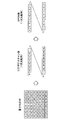
- the definition of the quantization matrix is given by transforming the two-dimensional array of the quantization matrix into a one-dimensional array by zigzag scanning and encoding the value of each element of the one-dimensional array using the DPCM (Differential Pulse Code Modulation) method. (See FIGS. 19 and 20).
- FIG. 19 shows a scan pattern of an existing zigzag scan.
- FIG. 20 conceptually shows a state of encoding by the zigzag scan and the DPCM method.
- HEVC High Efficiency Video Coding
- CU Coding Unit
- SCU Smallest Coding Unit
- one coding unit may be divided into one or more orthogonal transform units, that is, one or more transform units (TU).
- TU transform units
- any of 4 ⁇ 4, 8 ⁇ 8, 16 ⁇ 16, and 32 ⁇ 32 can be used.
- a quantization matrix can also be specified for each available transform unit size.
- Non-Patent Document 2 below defines a plurality of quantization matrix candidates for the size of one transform unit in one picture, and adaptively applies a quantization matrix for each block from the viewpoint of optimization of RD (Rate-Distortion). Suggest to choose.
- JCTVC-B205 "Test Model under Consideration”, Joint Collaborative Team on Video Coding (JCT-VC) of ITU-T SG16 WP3 and ISO / IEC JTC1 / SC29 / WG11 2nd Meeting: Geneva, CH, 21-28 July, 2010
- VCEG-AD06 "Adaptive Quantization Matrix Selection on KTA Software”
- the quantization matrix suitable for quantization and inverse quantization differs depending on the characteristics of each image included in the video. Therefore, H.H.
- the correlation between adjacent components in the one-dimensional array converted from the quantization matrix is not necessarily high, and as a result, the amount of code required for defining the quantization matrix is reduced. In some cases, it could not be compressed sufficiently.
- the number of quantization matrices defined accordingly increases. Therefore, it is expected that the need to further compress the code amount required for defining the quantization matrix will increase.
- the technology according to the present disclosure is intended to provide an image processing apparatus and an image processing method that can further compress the amount of code required for defining a quantization matrix.
- an acquisition unit that acquires a scan pattern parameter that specifies a scan pattern used when generating a quantization matrix among a plurality of scan patterns, and the scan pattern parameter acquired by the acquisition unit
- a generation unit that generates a quantization matrix using a scan pattern specified by the above, and an inverse quantization unit that dequantizes transform coefficient data of an image to be decoded using the quantization matrix generated by the generation unit
- the image processing apparatus can typically be realized as an image decoding apparatus that decodes an image.
- the acquisition unit acquires a presence parameter indicating whether the scan pattern parameter exists, and acquires the scan pattern parameter when the presence parameter indicates that the scan pattern parameter exists. Also good.
- the acquisition unit may acquire one existence parameter for a plurality of types of quantization matrices defined in the same parameter set.
- the generation unit generates a quantization matrix by decoding the predictive-coded one-dimensional array and reconstructing the decoded one-dimensional array into a matrix according to the scan pattern specified by the scan pattern parameter. May be.
- the generator when the scan pattern specified by the scan pattern parameter is a predetermined scan pattern, the generator generates at least one element of the one-dimensional array based on prediction from an element different from the immediately preceding element. May be decrypted.
- one of the plurality of scan patterns may be a scan pattern in which the uppermost row and the leftmost column of the quantization matrix are respectively scanned straight.
- acquiring a scan pattern parameter for specifying a scan pattern used when generating a quantization matrix among a plurality of scan patterns and specifying the acquired scan pattern parameter
- An image processing method includes generating a quantization matrix using the generated scan pattern and dequantizing the transform coefficient data of the decoded image using the generated quantization matrix.
- a quantization unit that quantizes transform coefficient data of an image to be encoded using a quantization matrix, and a quantization used by the quantization unit among a plurality of scan patterns
- An image processing apparatus includes an encoding unit that encodes a scan pattern parameter that specifies a scan pattern used when generating a matrix.
- the image processing apparatus can typically be realized as an image encoding apparatus that encodes an image.
- the image processing apparatus may further include a setting unit that sets a scan pattern that optimizes a code amount required for defining the quantization matrix among the plurality of scan patterns.
- the setting unit may select the scan pattern that optimizes the code amount offline.
- the image processing apparatus may further include a transmission unit that transmits an encoded stream including the scan pattern parameter encoded by the encoding unit to a device that decodes the image.
- encoding a scan pattern parameter that specifies a scan pattern used when generating a quantization matrix among a plurality of scan patterns, and transform coefficients of an image to be encoded
- An image processing method includes quantizing data using the quantization matrix.
- the image processing apparatus and the image processing method according to the present disclosure can further compress the code amount required for defining the quantization matrix.
- FIG. 2 is a block diagram illustrating an example of a detailed configuration of a syntax processing unit illustrated in FIG. 1. It is explanatory drawing which shows an example of the parameter for the definition of the quantization matrix which concerns on one Embodiment. It is explanatory drawing for demonstrating the 1st example of a new scan pattern. It is explanatory drawing for demonstrating the 2nd example of a new scan pattern. It is explanatory drawing for demonstrating the 3rd example of a new scan pattern. It is explanatory drawing for demonstrating the 4th example of a new scan pattern. It is explanatory drawing for demonstrating the 5th example of a new scan pattern.
- H. 2 is an explanatory diagram illustrating a scan pattern of a zigzag scan in H.264 / AVC. It is explanatory drawing which shows notionally the mode of the encoding by a zigzag scan and a DPCM system.
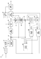
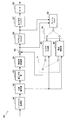
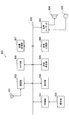
- FIG. 1 is a block diagram illustrating an example of a configuration of an image encoding device 10 according to an embodiment.
- an image encoding device 10 includes an A / D (Analogue to Digital) conversion unit 11, a rearrangement buffer 12, a syntax processing unit 13, a subtraction unit 14, an orthogonal transformation unit 15, a quantization unit 16, Lossless encoding unit 17, accumulation buffer 18, rate control unit 19, inverse quantization unit 21, inverse orthogonal transformation unit 22, addition unit 23, deblock filter 24, frame memory 25, selector 26, intra prediction unit 30, motion search Unit 40 and mode selection unit 50.
- a / D Analogue to Digital
- the A / D converter 11 converts an image signal input in an analog format into image data in a digital format, and outputs a series of digital image data to the rearrangement buffer 12.
- the rearrangement buffer 12 rearranges the images included in the series of image data input from the A / D conversion unit 11.
- the rearrangement buffer 12 rearranges the images according to a GOP (Group of Pictures) structure related to the encoding process, and then outputs the rearranged image data to the syntax processing unit 13.
- GOP Group of Pictures
- the syntax processing unit 13 sequentially recognizes NAL (Network Abstraction Layer) units in the stream of image data input from the rearrangement buffer 12, and inserts a non-VCL NAL unit that stores header information into the stream. To do.
- the non-VCL NAL unit inserted into the stream by the syntax processing unit 13 includes a sequence parameter set (SPS: Sequence Parameter Set) and a picture parameter set (PPS: Picture Parameter Set).
- SPS Sequence Parameter Set
- PPS Picture Parameter Set
- the syntax processing unit 13 adds a slice header to the head of the slice. Then, the syntax processing unit 13 outputs a stream of image data including the VCL NAL unit and the non-VCL NAL unit to the subtraction unit 14, the intra prediction unit 30, and the motion search unit 40.
- SPS Sequence Parameter Set
- PPS Picture Parameter Set
- the subtraction unit 14 is supplied with image data input from the syntax processing unit 13 and predicted image data selected by a mode selection unit 50 described later.
- the subtraction unit 14 calculates prediction error data that is a difference between the image data input from the syntax processing unit 13 and the predicted image data input from the mode selection unit 50, and the calculated prediction error data is orthogonally converted unit 15. Output to.
- the orthogonal transform unit 15 performs orthogonal transform on the prediction error data input from the subtraction unit 14.
- the orthogonal transformation performed by the orthogonal transformation part 15 may be discrete cosine transformation (Discrete Cosine Transform: DCT), Karoonen-Loeve transformation, etc., for example.
- the orthogonal transform unit 15 outputs transform coefficient data acquired by the orthogonal transform process to the quantization unit 16.
- the quantization unit 16 quantizes the transform coefficient data input from the orthogonal transform unit 15 using a quantization matrix, and transforms the quantized transform coefficient data (hereinafter referred to as quantized data) to the lossless encoding unit 17 and the inverse.
- the data is output to the quantization unit 21.
- the bit rate of the quantized data is controlled based on a rate control signal from the rate control unit 19.
- the quantization matrix used by the quantization unit 16 is defined in SPS or PPS, and can be specified in the slice header for each slice. If no quantization matrix is specified, a flat quantization matrix with equal quantization steps for all components is used.
- the lossless encoding unit 17 performs a lossless encoding process on the quantized data input from the quantization unit 16 to generate an encoded stream.
- the lossless encoding by the lossless encoding unit 17 may be, for example, variable length encoding or arithmetic encoding. Further, the lossless encoding unit 17 multiplexes information related to intra prediction or information related to inter prediction input from the mode selection unit 50 in the header of the encoded stream. Then, the lossless encoding unit 17 outputs the generated encoded stream to the accumulation buffer 18.
- the accumulation buffer 18 temporarily accumulates the encoded stream input from the lossless encoding unit 17 using a storage medium such as a semiconductor memory. Then, the accumulation buffer 18 outputs the accumulated encoded stream to a transmission unit (not shown) (for example, a communication interface or a connection interface with peripheral devices) at a rate corresponding to the bandwidth of the transmission path.
- a transmission unit for example, a communication interface or a connection interface with peripheral devices
- the rate control unit 19 monitors the free capacity of the storage buffer 18. Then, the rate control unit 19 generates a rate control signal according to the free capacity of the accumulation buffer 18 and outputs the generated rate control signal to the quantization unit 16. For example, the rate control unit 19 generates a rate control signal for reducing the bit rate of the quantized data when the free capacity of the storage buffer 18 is small. For example, when the free capacity of the storage buffer 18 is sufficiently large, the rate control unit 19 generates a rate control signal for increasing the bit rate of the quantized data.
- the inverse quantization unit 21 performs an inverse quantization process on the quantized data input from the quantization unit 16 using a quantization matrix. Then, the inverse quantization unit 21 outputs transform coefficient data acquired by the inverse quantization process to the inverse orthogonal transform unit 22.
- the inverse orthogonal transform unit 22 restores the prediction error data by performing an inverse orthogonal transform process on the transform coefficient data input from the inverse quantization unit 21. Then, the inverse orthogonal transform unit 22 outputs the restored prediction error data to the addition unit 23.
- the addition unit 23 generates decoded image data by adding the restored prediction error data input from the inverse orthogonal transform unit 22 and the predicted image data input from the mode selection unit 50. Then, the addition unit 23 outputs the generated decoded image data to the deblock filter 24 and the frame memory 25.
- the deblocking filter 24 performs a filtering process for reducing block distortion that occurs during image coding.
- the deblocking filter 24 removes block distortion by filtering the decoded image data input from the adding unit 23, and outputs the decoded image data after filtering to the frame memory 25.
- the frame memory 25 stores the decoded image data input from the adder 23 and the decoded image data after filtering input from the deblock filter 24 using a storage medium.
- the selector 26 reads out the decoded image data before filtering used for intra prediction from the frame memory 25 and supplies the read decoded image data to the intra prediction unit 30 as reference image data. Further, the selector 26 reads out the filtered decoded image data used for inter prediction from the frame memory 25 and supplies the read decoded image data to the motion search unit 40 as reference image data.
- the intra prediction unit 30 performs intra prediction processing in each intra prediction mode based on the image data to be encoded input from the syntax processing unit 13 and the decoded image data supplied via the selector 26. For example, the intra prediction unit 30 evaluates the prediction result in each intra prediction mode using a predetermined cost function. Then, the intra prediction unit 30 selects an intra prediction mode in which the cost function value is minimum, that is, an intra prediction mode in which the compression rate is the highest as the optimal intra prediction mode. Further, the intra prediction unit 30 outputs information related to intra prediction, such as prediction mode information indicating the optimal intra prediction mode, predicted image data, and cost function value, to the mode selection unit 50.
- the motion search unit 40 performs inter prediction processing (interframe prediction processing) based on the image data to be encoded input from the syntax processing unit 13 and the decoded image data supplied via the selector 26. For example, the motion search unit 40 evaluates the prediction result in each prediction mode using a predetermined cost function. Next, the motion search unit 40 selects a prediction mode with the smallest cost function value, that is, a prediction mode with the highest compression rate, as the optimum prediction mode. Further, the motion search unit 40 generates predicted image data according to the optimal prediction mode. Then, the motion search unit 40 outputs information related to inter prediction such as prediction mode information, prediction image data, and cost function values to the mode selection unit 50.
- inter prediction processing interframe prediction processing
- the mode selection unit 50 compares the cost function value related to intra prediction input from the intra prediction unit 30 with the cost function value related to inter prediction input from the motion search unit 40. And the mode selection part 50 selects the prediction method with few cost function values among intra prediction and inter prediction.
- the mode selection unit 50 outputs information on the intra prediction to the lossless encoding unit 17 and outputs the predicted image data to the subtraction unit 14 and the addition unit 23.
- the mode selection unit 50 outputs the above-described information regarding inter prediction to the lossless encoding unit 17 and outputs the predicted image data to the subtraction unit 14 and the addition unit 23.
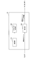
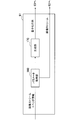
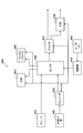
- FIG. 2 is a block diagram illustrating an example of a detailed configuration of the syntax processing unit 13 of the image encoding device 10 illustrated in FIG. 1.
- the syntax processing unit 13 includes a setting unit 110, a parameter generation unit 120, and an insertion unit 130.
- the setting unit 110 holds various settings used for encoding processing by the image encoding device 10.
- the setting unit 110 holds data relating to a profile of each sequence of image data, a coding mode of each picture, a GOP structure, and the like.
- the setting unit 110 holds settings for the quantization matrix used by the quantization unit 16 (and the inverse quantization unit 21).
- the setting unit 110 determines in advance for each slice, which quantization matrix to use by the quantization unit 16 based on the analysis of the image.
- the quantization matrix suitable for quantization and inverse quantization differs depending on the characteristics of each image included in the video.
- a quantization matrix having a smaller quantization step can be used even in a high frequency range.
- the quantization matrix changes in picture units or frame units.
- the complexity of the input image is low, the image quality perceived by the user can be improved by using a flat quantization matrix having a smaller quantization step.
- the complexity of the input image is high, it is desirable to use a larger quantization step in order to suppress an increase in the code amount.
- the distortion of the low-frequency signal may be recognized as block noise. Therefore, it is beneficial to reduce noise by using a quantization matrix in which the quantization step increases from the low range to the high range.
- MPEG2 compression distortion such as mosquito noise in the input image itself.
- Mosquito noise is noise generated as a result of quantizing a high-frequency signal with a larger quantization step, and the frequency component of the noise itself has a very high frequency.
- the interlace signal has a higher correlation between the signals in the horizontal direction than the correlation between the signals in the vertical direction due to the influence of interlaced scanning. Therefore, it is also beneficial to use a different quantization matrix depending on whether the image signal is a progressive signal or an interlace signal.
- each quantization matrix into a one-dimensional array for encoding
- a plurality of scan patterns including scan patterns other than the zigzag scan are prepared in advance.
- the setting unit 110 evaluates the code amount generated when the quantization matrix is encoded for each scan pattern, and selects an optimal scan pattern that minimizes the code amount.
- the determination of the quantization matrix and selection of the optimum scan pattern by the setting unit 110 are typically performed offline prior to image encoding. By selecting the optimum scan pattern offline, even when there are many scan pattern candidates, it is possible to appropriately find the optimum scan pattern using, for example, the brute force method. Then, the setting unit 110 holds, as the setting for the quantization matrix, the identifier of the optimum scan pattern selected offline for each quantization matrix defined in the parameter set.
- the parameter generation unit 120 generates a parameter that defines the setting for the encoding process held by the setting unit 110, and outputs the generated parameter to the insertion unit 130.
- the parameter generation unit 120 generates a parameter for defining a quantization matrix used by the quantization unit 16.
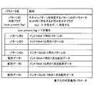
- FIG. 3 shows an example of parameters for defining the quantization matrix generated by the parameter generation unit 120.
- the “pattern ID presence flag” is a flag indicating whether or not a pattern ID that is a parameter for specifying a scan pattern exists in the parameter set (also referred to as a presence parameter).
- the pattern ID presence flag indicates “0: does not exist”, there is no pattern ID in the parameter set.
- the user-specific quantization matrix may be defined using zigzag scanning according to existing techniques.
- the pattern ID presence flag indicates “1: exists”, the pattern ID exists in the parameter set.
- Pattern ID is an ID (identifier) that identifies an optimal scan pattern for defining a quantization matrix (also referred to as a scan pattern parameter).
- a plurality of pattern IDs respectively associated with individual types of quantization matrices can be included.
- the type of quantization matrix is typically identified by a combination of size, prediction scheme (intra prediction / inter prediction) and signal component (Y / Cb / Cr component).
- the pattern ID1 is associated with the Y component of size 4 ⁇ 4 intra prediction
- the pattern ID2 is associated with the Cb component of size 4 ⁇ 4 intra prediction
- the pattern IDn is associated with the Y component of size 32 ⁇ 32 inter prediction. It has been.
- Array data is data of a one-dimensional array that is predictively encoded by the DPCM method and defines the values of the elements of the quantization matrix.
- array data 1 is a Y component for intra prediction of size 4 ⁇ 4
- array data 2 is a Cb component of intra prediction of size 4 ⁇ 4
- array data n is a Y component of inter prediction of size 32 ⁇ 32. The data associated with each.
- the insertion unit 130 inserts header information such as SPS, PPS, and a slice header, each including a parameter group generated by the parameter generation unit 120, into a stream of image data input from the rearrangement buffer 12. .
- the SPS and the PPS may include parameters for defining the quantization matrix as illustrated in FIG.
- the slice header may include a parameter that specifies a quantization matrix to be used for quantization and inverse quantization for the slice among quantization matrices defined by SPS or PPS. Then, the insertion unit 130 outputs the stream of image data in which the header information is inserted to the subtraction unit 14, the intra prediction unit 30, and the motion search unit 40.
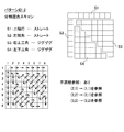
- Scan pattern candidates that can be set by the setting unit 110 of the syntax processing unit 13 include new scan patterns exemplified in FIGS. 4 to 8 in addition to the zigzag scan (see FIG. 19) that is an existing scan pattern. It's okay.
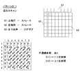
- FIG. 4 is an explanatory diagram for describing a first example of a new scan pattern.
- the scan pattern shown in FIG. 4 is referred to as “mixed scan” in this specification.
- the mixed scan the uppermost row and the leftmost column of the quantization matrix are scanned straight (S1, S2), and the remaining square elements are scanned zigzag (S3). Is a combined scan pattern.
- the element in the i-th row and j-th column of the quantization matrix is represented as (i, j).
- the mixed scan first, the eight elements (1, 1) to (1, 8) in the top row are scanned straight in the horizontal direction. Next, the seven elements (2, 1) to (8, 1) in the left end row are scanned straight in the vertical direction. Thereafter, the remaining lower right square elements (2, 2) to (8, 8) are scanned zigzag.
- the scan pattern is not a so-called one-stroke drawing like the existing zigzag scan, but has a branch in the middle of the scan pattern.
- the meaning of this branch is that the value of the element located in each branch is determined from the value of the element (two or more previous elements in the one-dimensional array) different from the previous element when encoding in the DPCM method. That is to be predicted.
- the element immediately before the first element (2, 1) of the straight scan in the leftmost column is the last element (1, 8) of the straight scan in the uppermost row.
- the element (1, 1) is used as a reference element instead of the element (1, 8).
- the difference between the value of the element (2, 1) and the value of the reference element (1, 1) is encoded.
- the element immediately before the first element (2, 2) of the lower right square zigzag scan is the last element (8, 1) of the straight scan of the left end column.
- the element (2, 1) is used as the reference element instead of the element (8, 1).
- the difference between the value of the element (2, 2) and the value of the reference element (2, 1) is encoded.
- an element encoded with reference to an element different from the immediately preceding element is referred to as a discontinuous reference element.
- the elements (2, 1) and (2, 2) are discontinuous reference elements.
- discontinuous reference element typically uses an element located closer to the two-dimensional quantization matrix as a reference element (element serving as a basis for prediction) instead of the immediately preceding element. This is because in a normally used quantization matrix, there is a high correlation of values between elements located near each other.
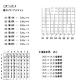
- FIG. 5 is an explanatory diagram for describing a second example of a new scan pattern.
- the scan pattern shown in FIG. 5 is referred to as “divided mixed scan” in this specification.
- the divided mixed scan first, the eight elements (1, 1) to (1, 8) in the upper end row are scanned straight in the horizontal direction (S1).
- the seven elements (2, 1) to (8, 1) in the left end row are scanned straight in the vertical direction (S2).
- the upper right triangular element groups (2, 2) to (8, 8) divided by diagonal lines in the remaining quadrangular regions are scanned zigzag (S3).
- the remaining lower left triangular element groups (3, 2) to (8, 7) are scanned zigzag (S4).
- the divided mixed scan also has a branch in the middle of the scan pattern.
- the elements (2, 1), (2, 2), and (3, 2) are discontinuous reference elements.
- the difference from the value of the reference element (1, 1) is encoded instead of the immediately preceding element (1, 8).
- the difference from the value of the reference element (2, 1) is encoded instead of the immediately preceding element (8, 1).
- the difference from the value of the reference element (2, 2) is encoded instead of the immediately preceding element (8, 8).
- Both the first example and the second example of the new scan pattern are scan patterns combining a straight scan and a zigzag scan.
- the straight scan is performed particularly on the uppermost row and the leftmost column of the quantization matrix.
- Such a scan pattern is useful when orthogonal transform coefficients are concentrated on the elements in the uppermost row and the leftmost column of the transform unit, and the correlation of the quantization step between these elements is high (in fact, Such quantization matrices can be used frequently).
- the second example is useful when the correlation between the upper right half element group and the lower left half element group is low, and it is better to scan these separately.
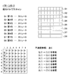
- FIG. 6 is an explanatory diagram for describing a third example of a new scan pattern.
- the scan pattern shown in FIG. 6 is a so-called field scan.
- the field scan has no branch in the middle of the scan pattern. Therefore, there is no discontinuous reference element in the field scan.
- the third example is useful when the correlation between quantization steps along the scan direction of the field scan is high.
- FIG. 7 is an explanatory diagram for describing a fourth example of a new scan pattern.
- the scan pattern shown in FIG. 7 is referred to as “vertical stripe scan” in this specification.
- vertical stripe scan first, the eight elements (1, 1) to (8, 1) in the left end row are scanned straight in the vertical direction (S1). Next, the eight elements (1, 2) to (8, 2) in the second column from the left are scanned straight in the vertical direction (S2). Thereafter, vertical scanning in the vertical direction is repeated in order from the third column to the eighth column (S3 to S8).
- the elements (1, 2), (1, 3), (1, 4), (1, 5), (1, 6), (1, 7) and (1, 8) are discontinuous.
- Reference element When the element (1, 2) is encoded, the difference from the value of the reference element (1, 1) is encoded instead of the immediately preceding element (8, 1). When encoding the element (1, 3), the difference from the value of the reference element (1, 2) is encoded instead of the immediately preceding element (8, 2). Also for other discontinuous reference elements, not the immediately preceding element in the one-dimensional array after scanning, but the difference from the values of two or more previous elements is encoded.
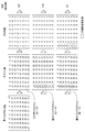
- FIG. 8 is an explanatory diagram for describing a fifth example of a new scan pattern.
- the scan pattern shown in FIG. 8 is referred to as “horizontal stripe scan” in this specification.
- the horizontal stripe scan first, the eight elements (1, 1) to (1, 8) in the upper end row are scanned straight in the horizontal direction (S1).
- the eight elements (2, 1) to (2, 8) in the second row from the top are scanned straight in the horizontal direction (S2).
- the horizontal straight scan is sequentially repeated from the third row to the eighth row (S3 to S8).
- the horizontal stripe scan has a branch in the middle of the scan pattern.
- elements (2,1), (3,1), (4,1), (5,1), (6,1), (7,1) and (8,1) are discontinuous Reference element.
- the difference from the value of the reference element (1, 1) is encoded instead of the immediately preceding element (1, 8).
- the difference from the value of the reference element (2, 1) is encoded instead of the immediately preceding element (2, 8).
- the immediately preceding element in the one-dimensional array after scanning but the difference from the values of two or more previous elements is encoded.
- the fourth example and the fifth example of the new scan pattern are both scan patterns composed of only a straight scan. Such a scan pattern is when the correlation of quantization steps between elements along one of the vertical and horizontal directions is high and the correlation of quantization steps between elements along the other is low. Useful.
- FIG. 9 is a flowchart showing an example of the flow of parameter generation processing by the parameter generation unit 120 of the syntax processing unit 13 according to the present embodiment.
- the parameter generation process shown in FIG. 9 is a process that can be executed for a quantization matrix to be defined when there is a quantization matrix to be newly defined.
- the parameter generation unit 120 recognizes the optimum scan pattern selected offline by the setting unit 110 corresponding to the quantization matrix to be newly defined (step S100).
- the subsequent steps S104 to S110 are repeated for each element of the quantization matrix (step S102).
- the order of the elements to be processed follows the scan pattern recognized in step S100.
- the parameter generation unit 120 acquires the value of an element to be processed (hereinafter referred to as a target element) in the quantization matrix according to the scan pattern (step S104).
- the parameter generation unit 120 determines whether or not the element of interest is a discontinuous reference element (step S106). If the target element is not a discontinuous reference element, the parameter generation unit 120 determines the difference value between the immediately preceding element (the previous target element) and the target element (for the first target element, the target element Is stored in a one-dimensional array (step S108). On the other hand, if the element of interest is a discontinuous reference element, the parameter generation unit 120 stores the difference value between the predetermined reference element before the immediately preceding element and the element of interest in a one-dimensional array (step) S110).
- a set of pattern IDk and array data k (k is any one of 1 to n) is generated.
- the parameter generation unit 120 performs the above-described parameter generation processing on a quantization matrix (one or more types) to be newly defined, for example, at the timing when SPS or PPS is inserted into a stream of image data.
- the parameters generated by the parameter generation unit 120 are included in the SPS or PPS by the insertion unit 130.
- the pattern ID presence flag indicates “1: exists”.
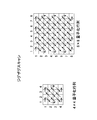
- FIG. 10B there is shown a quantization matrix QM B as another example that may be defined by the user.
- QM B the sequence shown in the upper center of FIG. (6,6,10,13, ..., 27) is derived.
- the one-dimensional array generated by the zigzag scan is encoded according to the DPCM method, the one-dimensional array (6, 0, 4, 3,..., 0) of the difference values shown on the upper right of the figure is derived.
- the total sum of absolute values of the elements of the one-dimensional array of difference values generated in this way is 167.
- the setting unit 110 may evaluate the code amount for each scan pattern in this way for each quantization matrix, and may select the optimum scan pattern with the smallest code amount. Thereby, compared with the case where a quantization matrix is uniformly arranged in a one-dimensional array by zigzag scanning, the amount of code required for defining the quantization matrix can be further compressed.
- the elements surrounded by the dotted frame are discontinuous reference elements.
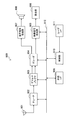
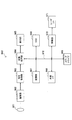
- FIG. 11 is a block diagram illustrating an example of the configuration of the image decoding device 60 according to an embodiment.
- the image decoding device 60 includes a syntax processing unit 61, a lossless decoding unit 62, an inverse quantization unit 63, an inverse orthogonal transform unit 64, an addition unit 65, a deblocking filter 66, a rearrangement buffer 67, a D / A (Digital to Analogue) conversion unit 68, frame memory 69, selectors 70 and 71, intra prediction unit 80, and motion compensation unit 90.
- a syntax processing unit 61 includes a syntax processing unit 61, a lossless decoding unit 62, an inverse quantization unit 63, an inverse orthogonal transform unit 64, an addition unit 65, a deblocking filter 66, a rearrangement buffer 67, a D / A (Digital to Analogue) conversion unit 68, frame memory 69, selectors 70 and 71, intra prediction unit 80, and motion compensation unit 90.
- the syntax processing unit 61 acquires header information such as SPS, PPS, and slice header from the encoded stream input via the transmission path, and performs decoding processing by the image decoding device 60 based on the acquired header information. Recognize various settings. For example, in the present embodiment, the syntax processing unit 61 generates a quantization matrix used in the inverse quantization process by the inverse quantization unit 63 based on the parameters included in the SPS or PPS. The detailed configuration of the syntax processing unit 61 will be further described later.
- the lossless decoding unit 62 decodes the encoded stream input from the syntax processing unit 61 according to the encoding method used for encoding. Then, the lossless decoding unit 62 outputs the decoded quantized data to the inverse quantization unit 63. Further, the lossless decoding unit 62 outputs information related to intra prediction included in the header information to the intra prediction unit 80, and outputs information related to inter prediction to the motion compensation unit 90.
- the inverse quantization unit 63 uses the quantization matrix generated by the syntax processing unit 61 to inversely quantize the quantized data (that is, quantized transform coefficient data) after being decoded by the lossless decoding unit 62. .
- the quantization matrices generated by the syntax processing unit 61 which quantization matrix should be used for each block in a certain slice can be specified in the slice header.
- the inverse orthogonal transform unit 64 generates prediction error data by performing inverse orthogonal transform on the transform coefficient data input from the inverse quantization unit 63 in accordance with the orthogonal transform method used at the time of encoding. Then, the inverse orthogonal transform unit 64 outputs the generated prediction error data to the addition unit 65.
- the addition unit 65 adds the prediction error data input from the inverse orthogonal transform unit 64 and the prediction image data input from the selector 71 to generate decoded image data. Then, the addition unit 65 outputs the generated decoded image data to the deblock filter 66 and the frame memory 69.
- the deblocking filter 66 removes block distortion by filtering the decoded image data input from the adding unit 65, and outputs the decoded image data after filtering to the rearrangement buffer 67 and the frame memory 69.
- the rearrangement buffer 67 rearranges the images input from the deblock filter 66 to generate a series of time-series image data. Then, the rearrangement buffer 67 outputs the generated image data to the D / A conversion unit 68.
- the D / A converter 68 converts the digital image data input from the rearrangement buffer 67 into an analog image signal. Then, the D / A conversion unit 68 displays an image by outputting an analog image signal to a display (not shown) connected to the image decoding device 60, for example.
- the frame memory 69 stores the decoded image data before filtering input from the adding unit 65 and the decoded image data after filtering input from the deblocking filter 66 using a storage medium.
- the selector 70 switches the output destination of the image data from the frame memory 69 between the intra prediction unit 80 and the motion compensation unit 90 for each block in the image according to the mode information acquired by the lossless decoding unit 62. .
- the selector 70 outputs the decoded image data before filtering supplied from the frame memory 69 to the intra prediction unit 80 as reference image data.
- the selector 70 outputs the decoded image data after filtering supplied from the frame memory 69 to the motion compensation unit 90 as reference image data.
- the selector 71 sets the output source of the predicted image data to be supplied to the adding unit 65 for each block in the image according to the mode information acquired by the lossless decoding unit 62 between the intra prediction unit 80 and the motion compensation unit 90. Switch between. For example, the selector 71 supplies the prediction image data output from the intra prediction unit 80 to the adding unit 65 when the intra prediction mode is designated. The selector 71 supplies the predicted image data output from the motion compensation unit 90 to the adding unit 65 when the inter prediction mode is designated.
- the intra prediction unit 80 performs in-screen prediction of pixel values based on information related to intra prediction input from the lossless decoding unit 62 and reference image data from the frame memory 69, and generates predicted image data. Then, the intra prediction unit 80 outputs the generated predicted image data to the selector 71.
- the motion compensation unit 90 performs motion compensation processing based on the inter prediction information input from the lossless decoding unit 62 and the reference image data from the frame memory 69, and generates predicted image data. Then, the motion compensation unit 90 outputs the generated predicted image data to the selector 71.
- FIG. 12 is a block diagram illustrating an example of a detailed configuration of the syntax processing unit 61 of the image decoding device 60 illustrated in FIG. 11.
- the syntax processing unit 61 includes a parameter acquisition unit 160 and a generation unit 170.
- the parameter acquisition unit 160 recognizes header information such as SPS, PPS, and slice header from the image data stream, and acquires parameters included in the header information. For example, in this embodiment, the parameter acquisition unit 160 acquires a parameter that defines a quantization matrix from SPS or PPS.
- the parameters that define the quantization matrix may include a pattern ID presence flag as exemplified in FIG. 3, and a pattern ID and array data for each type of quantization matrix. Then, the parameter acquisition unit 160 outputs the acquired parameters to the generation unit 170. Also, the parameter acquisition unit 160 outputs a stream of image data to the lossless decoding unit 62.
- the generation unit 170 generates various data used in the processing by each unit illustrated in FIG. 11 based on the parameters acquired by the parameter acquisition unit 160. For example, the generation unit 170 recognizes the range of the size of the encoding unit from the set of LCU and SCU values, and sets the size of the encoding unit according to the value of split_flag. Image data is decoded using the encoding unit set here as a unit of processing. In addition, the generation unit 170 further sets the size of the conversion unit. The inverse quantization performed by the inverse quantization unit 63 and the inverse orthogonal transform performed by the inverse orthogonal transform unit 64 are performed using the transform unit set here as a processing unit.
- the generation unit 170 generates a quantization matrix based on the parameters acquired from the SPS or PPS by the parameter acquisition unit 160. More specifically, the generation unit 170 decodes array data that is a predictive-coded one-dimensional array according to the DPCM method, and reconstructs the decoded one-dimensional array into a two-dimensional quantization matrix. When a pattern ID that specifies one of a plurality of scan patterns is acquired from the parameter set, the reconstruction of the quantization matrix from the one-dimensional array is performed using the scan pattern specified by the pattern ID. Is called.
- the generation unit 170 determines at least one discontinuous reference element of the one-dimensional array based on a prediction from a reference element different from the immediately preceding element.
- the predetermined scan pattern can include, for example, the above-described mixed scan, divided mixed scan, vertical stripe scan, and horizontal stripe scan.
- the reconstruction of the quantization matrix is performed with a scan pattern of zigzag scan.
- the generation unit 170 can determine whether a pattern ID exists in the parameter set from the value indicated by the pattern ID presence flag. Only one pattern ID presence flag may be provided in common for a plurality of types of quantization matrices defined in the same parameter set. As a result, when a quantization matrix is to be defined according to an existing method, it can be simply indicated by a small code amount that there is no pattern ID.
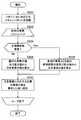
- FIG. 13 is a flowchart showing an exemplary flow of a quantization matrix generation process by the syntax processing unit 61 according to this embodiment.
- the quantization matrix generation process of FIG. 13 is a process that can be performed every time SPS or PPS is detected in a stream of image data.
- the parameter acquisition unit 160 first acquires a pattern ID presence flag from the SPS or PPS (step S200). The subsequent processing in steps S204 to S212 is repeated for each type of quantization matrix (step S202).
- step S204 the parameter acquisition unit 160 determines whether a pattern ID exists in the parameter set from the value indicated by the pattern ID presence flag (step S204). If it is determined that there is a pattern ID, the parameter acquisition unit 160 further acquires a pattern ID and array data for the type of quantization matrix to be processed (step S206). Then, the generation unit 170 performs a quantization matrix reconstruction process illustrated in FIG. 14 (Step S208). On the other hand, when it is determined that the pattern ID does not exist, the parameter acquisition unit 160 further acquires only the array data regarding the type of the quantization matrix to be processed (step S210). Then, the generation unit 170 performs a quantization matrix reconstruction process using a zigzag scan as in the existing method (step S212).
- FIG. 14 is a flowchart showing an example of a detailed flow of the quantization matrix reconstruction process in step S208 of FIG.
- the generation unit 170 recognizes a scan pattern corresponding to the pattern ID acquired by the parameter acquisition unit 160 (step S220).
- the subsequent processing in steps S224 to S230 is repeated for each element of the one-dimensional array included in the array data (step S222).
- step S224 the generation unit 170 determines whether or not the element of interest is a discontinuous reference element (step S224). If the target element is not a discontinuous reference element, the generation unit 170 adds the difference value of the target element included in the array data to the decoded value of the immediately preceding element (the previous target element), The decoded value of the element of interest is calculated (step S226). On the other hand, when the target element is a discontinuous reference element, the generation unit 170 adds the difference value of the target element to the decoded value of the predetermined reference element before the previous element, thereby generating the target element. Is calculated (step S228). Next, the generation unit 170 sets the value of the element corresponding to the element of interest in the quantization matrix to the value calculated in step S226 or S228 (step S230).
- the image encoding device 10 and the image decoding device 60 include a transmitter or a receiver in satellite broadcasting, cable broadcasting such as cable TV, distribution on the Internet, and distribution to terminals by cellular communication,
- the present invention can be applied to various electronic devices such as a recording apparatus that records an image on a medium such as an optical disk, a magnetic disk, and a flash memory, or a reproducing apparatus that reproduces an image from the storage medium.
- a recording apparatus that records an image on a medium such as an optical disk, a magnetic disk, and a flash memory
- a reproducing apparatus that reproduces an image from the storage medium.
- FIG. 15 shows an example of a schematic configuration of a television apparatus to which the above-described embodiment is applied.
- the television apparatus 900 includes an antenna 901, a tuner 902, a demultiplexer 903, a decoder 904, a video signal processing unit 905, a display unit 906, an audio signal processing unit 907, a speaker 908, an external interface 909, a control unit 910, a user interface 911, And a bus 912.
- Tuner 902 extracts a signal of a desired channel from a broadcast signal received via antenna 901, and demodulates the extracted signal. Then, the tuner 902 outputs the encoded bit stream obtained by the demodulation to the demultiplexer 903. In other words, the tuner 902 serves as a transmission unit in the television apparatus 900 that receives an encoded stream in which an image is encoded.
- the demultiplexer 903 separates the video stream and audio stream of the viewing target program from the encoded bit stream, and outputs each separated stream to the decoder 904. In addition, the demultiplexer 903 extracts auxiliary data such as EPG (Electronic Program Guide) from the encoded bit stream, and supplies the extracted data to the control unit 910. Note that the demultiplexer 903 may perform descrambling when the encoded bit stream is scrambled.
- EPG Electronic Program Guide
- the decoder 904 decodes the video stream and audio stream input from the demultiplexer 903. Then, the decoder 904 outputs the video data generated by the decoding process to the video signal processing unit 905. In addition, the decoder 904 outputs audio data generated by the decoding process to the audio signal processing unit 907.
- the video signal processing unit 905 reproduces the video data input from the decoder 904 and causes the display unit 906 to display the video.
- the video signal processing unit 905 may cause the display unit 906 to display an application screen supplied via a network.
- the video signal processing unit 905 may perform additional processing such as noise removal on the video data according to the setting.
- the video signal processing unit 905 may generate a GUI (Graphical User Interface) image such as a menu, a button, or a cursor, and superimpose the generated image on the output image.
- GUI Graphic User Interface
- the display unit 906 is driven by a drive signal supplied from the video signal processing unit 905, and displays a video or an image on a video screen of a display device (for example, a liquid crystal display, a plasma display, or an OLED).
- a display device for example, a liquid crystal display, a plasma display, or an OLED.
- the audio signal processing unit 907 performs reproduction processing such as D / A conversion and amplification on the audio data input from the decoder 904, and outputs audio from the speaker 908.
- the audio signal processing unit 907 may perform additional processing such as noise removal on the audio data.
- the external interface 909 is an interface for connecting the television apparatus 900 to an external device or a network.
- a video stream or an audio stream received via the external interface 909 may be decoded by the decoder 904. That is, the external interface 909 also has a role as a transmission unit in the television apparatus 900 that receives an encoded stream in which an image is encoded.
- the control unit 910 has a processor such as a CPU (Central Processing Unit) and a memory such as a RAM (Random Access Memory) and a ROM (Read Only Memory).
- the memory stores a program executed by the CPU, program data, EPG data, data acquired via a network, and the like.
- the program stored in the memory is read and executed by the CPU when the television device 900 is activated, for example.
- the CPU controls the operation of the television device 900 according to an operation signal input from the user interface 911, for example, by executing the program.
- the user interface 911 is connected to the control unit 910.
- the user interface 911 includes, for example, buttons and switches for the user to operate the television device 900, a remote control signal receiving unit, and the like.
- the user interface 911 detects an operation by the user via these components, generates an operation signal, and outputs the generated operation signal to the control unit 910.
- the bus 912 connects the tuner 902, the demultiplexer 903, the decoder 904, the video signal processing unit 905, the audio signal processing unit 907, the external interface 909, and the control unit 910 to each other.
- the decoder 904 has the function of the image decoding apparatus 60 according to the above-described embodiment. Therefore, it is possible to compress the code amount required for defining the quantization matrix for the video decoded by the television apparatus 900.
- FIG. 16 shows an example of a schematic configuration of a mobile phone to which the above-described embodiment is applied.
- a mobile phone 920 includes an antenna 921, a communication unit 922, an audio codec 923, a speaker 924, a microphone 925, a camera unit 926, an image processing unit 927, a demultiplexing unit 928, a recording / reproducing unit 929, a display unit 930, a control unit 931, an operation A portion 932 and a bus 933.
- the antenna 921 is connected to the communication unit 922.
- the speaker 924 and the microphone 925 are connected to the audio codec 923.
- the operation unit 932 is connected to the control unit 931.
- the bus 933 connects the communication unit 922, the audio codec 923, the camera unit 926, the image processing unit 927, the demultiplexing unit 928, the recording / reproducing unit 929, the display unit 930, and the control unit 931 to each other.
- the mobile phone 920 has various operation modes including a voice call mode, a data communication mode, a shooting mode, and a videophone mode, and is used for sending and receiving voice signals, sending and receiving e-mail or image data, taking images, and recording data. Perform the action.
- the analog voice signal generated by the microphone 925 is supplied to the voice codec 923.
- the audio codec 923 converts an analog audio signal into audio data, A / D converts the compressed audio data, and compresses it. Then, the audio codec 923 outputs the compressed audio data to the communication unit 922.
- the communication unit 922 encodes and modulates the audio data and generates a transmission signal. Then, the communication unit 922 transmits the generated transmission signal to a base station (not shown) via the antenna 921. In addition, the communication unit 922 amplifies a radio signal received via the antenna 921 and performs frequency conversion to acquire a received signal.
- the communication unit 922 demodulates and decodes the received signal to generate audio data, and outputs the generated audio data to the audio codec 923.
- the audio codec 923 expands the audio data and performs D / A conversion to generate an analog audio signal. Then, the audio codec 923 supplies the generated audio signal to the speaker 924 to output audio.
- the control unit 931 generates character data constituting the e-mail in response to an operation by the user via the operation unit 932.
- the control unit 931 causes the display unit 930 to display characters.
- the control unit 931 generates e-mail data in response to a transmission instruction from the user via the operation unit 932, and outputs the generated e-mail data to the communication unit 922.
- the communication unit 922 encodes and modulates email data and generates a transmission signal. Then, the communication unit 922 transmits the generated transmission signal to a base station (not shown) via the antenna 921.
- the communication unit 922 amplifies a radio signal received via the antenna 921 and performs frequency conversion to acquire a received signal.
- the communication unit 922 demodulates and decodes the received signal to restore the email data, and outputs the restored email data to the control unit 931.
- the control unit 931 displays the content of the electronic mail on the display unit 930 and stores the electronic mail data in the storage medium of the recording / reproducing unit 929.
- the recording / reproducing unit 929 has an arbitrary readable / writable storage medium.
- the storage medium may be a built-in storage medium such as a RAM or a flash memory, or an externally mounted storage medium such as a hard disk, a magnetic disk, a magneto-optical disk, an optical disk, a USB memory, or a memory card. May be.
- the camera unit 926 images a subject to generate image data, and outputs the generated image data to the image processing unit 927.
- the image processing unit 927 encodes the image data input from the camera unit 926 and stores the encoded stream in the storage medium of the recording / playback unit 929.
- the demultiplexing unit 928 multiplexes the video stream encoded by the image processing unit 927 and the audio stream input from the audio codec 923, and the multiplexed stream is the communication unit 922. Output to.
- the communication unit 922 encodes and modulates the stream and generates a transmission signal. Then, the communication unit 922 transmits the generated transmission signal to a base station (not shown) via the antenna 921.
- the communication unit 922 amplifies a radio signal received via the antenna 921 and performs frequency conversion to acquire a received signal.
- These transmission signal and reception signal may include an encoded bit stream.
- the communication unit 922 demodulates and decodes the received signal to restore the stream, and outputs the restored stream to the demultiplexing unit 928.
- the demultiplexing unit 928 separates the video stream and the audio stream from the input stream, and outputs the video stream to the image processing unit 927 and the audio stream to the audio codec 923.
- the image processing unit 927 decodes the video stream and generates video data.
- the video data is supplied to the display unit 930, and a series of images is displayed on the display unit 930.
- the audio codec 923 decompresses the audio stream and performs D / A conversion to generate an analog audio signal. Then, the audio codec 923 supplies the generated audio signal to the speaker 924 to output audio.
- the image processing unit 927 has the functions of the image encoding device 10 and the image decoding device 60 according to the above-described embodiment. Therefore, the amount of code required to define the quantization matrix can be compressed for video encoded and decoded by the mobile phone 920.
- FIG. 17 shows an example of a schematic configuration of a recording / reproducing apparatus to which the above-described embodiment is applied.
- the recording / reproducing device 940 encodes audio data and video data of a received broadcast program and records the encoded data on a recording medium.
- the recording / reproducing device 940 may encode audio data and video data acquired from another device and record them on a recording medium, for example.
- the recording / reproducing device 940 reproduces data recorded on the recording medium on a monitor and a speaker, for example, in accordance with a user instruction. At this time, the recording / reproducing device 940 decodes the audio data and the video data.
- the recording / reproducing device 940 includes a tuner 941, an external interface 942, an encoder 943, an HDD (Hard Disk Drive) 944, a disk drive 945, a selector 946, a decoder 947, an OSD (On-Screen Display) 948, a control unit 949, and a user interface. 950.
- Tuner 941 extracts a signal of a desired channel from a broadcast signal received via an antenna (not shown), and demodulates the extracted signal. Then, the tuner 941 outputs the encoded bit stream obtained by the demodulation to the selector 946. That is, the tuner 941 has a role as a transmission unit in the recording / reproducing apparatus 940.
- the external interface 942 is an interface for connecting the recording / reproducing apparatus 940 to an external device or a network.
- the external interface 942 may be, for example, an IEEE 1394 interface, a network interface, a USB interface, or a flash memory interface.
- video data and audio data received via the external interface 942 are input to the encoder 943. That is, the external interface 942 serves as a transmission unit in the recording / reproducing device 940.
- the encoder 943 encodes video data and audio data when the video data and audio data input from the external interface 942 are not encoded. Then, the encoder 943 outputs the encoded bit stream to the selector 946.
- the HDD 944 records an encoded bit stream in which content data such as video and audio is compressed, various programs, and other data on an internal hard disk. Also, the HDD 944 reads out these data from the hard disk when playing back video and audio.
- the disk drive 945 performs recording and reading of data to and from the mounted recording medium.
- the recording medium loaded in the disk drive 945 may be, for example, a DVD disk (DVD-Video, DVD-RAM, DVD-R, DVD-RW, DVD + R, DVD + RW, etc.) or a Blu-ray (registered trademark) disk. .
- the selector 946 selects an encoded bit stream input from the tuner 941 or the encoder 943 when recording video and audio, and outputs the selected encoded bit stream to the HDD 944 or the disk drive 945. In addition, the selector 946 outputs the encoded bit stream input from the HDD 944 or the disk drive 945 to the decoder 947 during video and audio reproduction.
- the decoder 947 decodes the encoded bit stream and generates video data and audio data. Then, the decoder 947 outputs the generated video data to the OSD 948. The decoder 904 outputs the generated audio data to an external speaker.
- the OSD 948 reproduces the video data input from the decoder 947 and displays the video. Further, the OSD 948 may superimpose a GUI image such as a menu, a button, or a cursor on the video to be displayed.
- a GUI image such as a menu, a button, or a cursor
- the control unit 949 includes a processor such as a CPU and memories such as a RAM and a ROM.
- the memory stores a program executed by the CPU, program data, and the like.
- the program stored in the memory is read and executed by the CPU when the recording / reproducing apparatus 940 is activated, for example.
- the CPU controls the operation of the recording / reproducing device 940 according to an operation signal input from the user interface 950, for example, by executing the program.
- the user interface 950 is connected to the control unit 949.
- the user interface 950 includes, for example, buttons and switches for the user to operate the recording / reproducing device 940, a remote control signal receiving unit, and the like.
- the user interface 950 detects an operation by the user via these components, generates an operation signal, and outputs the generated operation signal to the control unit 949.
- the encoder 943 has the function of the image encoding apparatus 10 according to the above-described embodiment.
- the decoder 947 has the function of the image decoding device 60 according to the above-described embodiment. Therefore, the code amount required for defining the quantization matrix can be compressed for the video encoded and decoded by the recording / reproducing apparatus 940.
- FIG. 18 illustrates an example of a schematic configuration of an imaging apparatus to which the above-described embodiment is applied.
- the imaging device 960 images a subject to generate an image, encodes the image data, and records it on a recording medium.
- the imaging device 960 includes an optical block 961, an imaging unit 962, a signal processing unit 963, an image processing unit 964, a display unit 965, an external interface 966, a memory 967, a media drive 968, an OSD 969, a control unit 970, a user interface 971, and a bus. 972.
- the optical block 961 is connected to the imaging unit 962.
- the imaging unit 962 is connected to the signal processing unit 963.
- the display unit 965 is connected to the image processing unit 964.
- the user interface 971 is connected to the control unit 970.
- the bus 972 connects the image processing unit 964, the external interface 966, the memory 967, the media drive 968, the OSD 969, and the control unit 970 to each other.
- the optical block 961 includes a focus lens and a diaphragm mechanism.
- the optical block 961 forms an optical image of the subject on the imaging surface of the imaging unit 962.
- the imaging unit 962 includes an image sensor such as a CCD or a CMOS, and converts an optical image formed on the imaging surface into an image signal as an electrical signal by photoelectric conversion. Then, the imaging unit 962 outputs the image signal to the signal processing unit 963.
- the signal processing unit 963 performs various camera signal processing such as knee correction, gamma correction, and color correction on the image signal input from the imaging unit 962.
- the signal processing unit 963 outputs the image data after the camera signal processing to the image processing unit 964.
- the image processing unit 964 encodes the image data input from the signal processing unit 963 and generates encoded data. Then, the image processing unit 964 outputs the generated encoded data to the external interface 966 or the media drive 968. The image processing unit 964 also decodes encoded data input from the external interface 966 or the media drive 968 to generate image data. Then, the image processing unit 964 outputs the generated image data to the display unit 965. In addition, the image processing unit 964 may display the image by outputting the image data input from the signal processing unit 963 to the display unit 965. Further, the image processing unit 964 may superimpose display data acquired from the OSD 969 on an image output to the display unit 965.
- the OSD 969 generates a GUI image such as a menu, a button, or a cursor, for example, and outputs the generated image to the image processing unit 964.
- the external interface 966 is configured as a USB input / output terminal, for example.
- the external interface 966 connects the imaging device 960 and a printer, for example, when printing an image.
- a drive is connected to the external interface 966 as necessary.
- a removable medium such as a magnetic disk or an optical disk is attached to the drive, and a program read from the removable medium can be installed in the imaging device 960.
- the external interface 966 may be configured as a network interface connected to a network such as a LAN or the Internet. That is, the external interface 966 has a role as a transmission unit in the imaging device 960.
- the recording medium mounted on the media drive 968 may be any readable / writable removable medium such as a magnetic disk, a magneto-optical disk, an optical disk, or a semiconductor memory. Further, a recording medium may be fixedly attached to the media drive 968, and a non-portable storage unit such as an internal hard disk drive or an SSD (Solid State Drive) may be configured.
- a non-portable storage unit such as an internal hard disk drive or an SSD (Solid State Drive) may be configured.
- the control unit 970 includes a processor such as a CPU and memories such as a RAM and a ROM.
- the memory stores a program executed by the CPU, program data, and the like.
- the program stored in the memory is read and executed by the CPU when the imaging device 960 is activated, for example.
- the CPU controls the operation of the imaging device 960 according to an operation signal input from the user interface 971, for example, by executing the program.
- the user interface 971 is connected to the control unit 970.
- the user interface 971 includes, for example, buttons and switches for the user to operate the imaging device 960.
- the user interface 971 detects an operation by the user via these components, generates an operation signal, and outputs the generated operation signal to the control unit 970.
- the image processing unit 964 has the functions of the image encoding device 10 and the image decoding device 60 according to the above-described embodiment. Therefore, it is possible to compress the amount of code required for defining the quantization matrix for the video encoded and decoded by the imaging device 960.
- the quantization matrix used in the quantization or inverse quantization of the transform coefficient data of the image is encoded using a scan pattern that is adaptively selected from a plurality of scan patterns. Or decrypted. Thereby, compared with the case where a zigzag scan is used uniformly, the code amount required for the definition of a quantization matrix can be compressed more.
- a flag indicating whether or not a pattern ID for specifying a scan pattern exists in the parameter set is inserted in the parameter set.
- One flag may be provided for a plurality of types of quantization matrices defined in the same parameter set. Therefore, when a quantization matrix is to be defined according to an existing method, it can be simply indicated that a pattern ID does not exist with a small code amount. As a result, the above-described adaptive scan pattern selection mechanism can be introduced without significantly affecting the existing apparatus.
- a discontinuous reference element can be adopted for a predetermined scan pattern.
- the encoding or decoding of the discontinuous reference element in the DPCM method is performed based on prediction from a reference element different from the element immediately before the one-dimensional array to be scanned.
- the parameters for defining the quantization matrix are multiplexed on the header of the encoded stream and transmitted from the encoding side to the decoding side.
- the method of transmitting these parameters is not limited to such an example.
- the parameters may be transmitted or recorded as separate data associated with the encoded bitstream without being multiplexed into the encoded bitstream.
- the term “associate” means that an image (which may be a part of an image such as a slice or a block) included in the bitstream and information corresponding to the image can be linked at the time of decoding. Means. That is, information may be transmitted on a transmission path different from that of the image (or bit stream).
- the information may be recorded on a recording medium (or another recording area of the same recording medium) different from the image (or bit stream). Furthermore, the information and the image (or the bit stream) may be associated with each other in an arbitrary unit such as a plurality of frames, one frame, or a part of the frame.
- Image processing device image encoding device
- quantization unit 110 setting unit 120 parameter generation unit 130 insertion unit
- parameter generation unit 120 parameter generation unit
- insertion unit 60 image processing device (image decoding device)
- Inverse quantization unit 160 Parameter acquisition unit 170 Generation unit
Landscapes
- Engineering & Computer Science (AREA)
- Multimedia (AREA)
- Signal Processing (AREA)
- Compression Or Coding Systems Of Tv Signals (AREA)
Abstract
【課題】量子化行列の定義に要する符号量をより圧縮すること。 【解決手段】複数のスキャンパターンのうち量子化行列の生成の際に使用されるスキャンパターンを特定するスキャンパターンパラメータを取得する取得部と、上記取得部により取得される上記スキャンパターンパラメータにより特定されるスキャンパターンを用いて量子化行列を生成する生成部と、上記生成部により生成される量子化行列を用いて、復号される画像の変換係数データを逆量子化する逆量子化部と、を備える画像処理装置を提供する。
Description
本開示は、画像処理装置及び画像処理方法に関する。
画像符号化方式の標準仕様の1つであるH.264/AVCでは、High Profile以上のプロファイルにおいて、画像データの量子化の際に、直交変換係数の成分ごとに異なる量子化ステップを用いることができる。直交変換係数の成分ごとの量子化ステップは、直交変換の単位と同等のサイズで定義される量子化行列(スケーリングリストともいう)及び基準のステップ値に基づいて設定され得る。
H.264/AVCでは、ユーザは、サイズ、予測方式(イントラ予測/インター予測)及び信号成分(Y/Cb/Cr成分)の組合せごとに予め用意される既定の量子化行列を使用することができる。また、ユーザは、既定の量子化行列とは別に、独自の量子化行列を定義することもできる。ユーザ独自の量子化行列は、シーケンスパラメータセット又はピクチャパラメータセットにおいて定義される。量子化行列の定義は、量子化行列の二次元配列をジグザグスキャンによって1次元配列に変形し、1次元配列の各要素の値をDPCM(Differential Pulse Code Modulation)方式で符号化することにより与えられる(図19、図20参照)。図19は、既存のジグザグスキャンのスキャンパターンを示している。図20は、ジグザグスキャン及びDPCM方式での符号化の様子を概念的に示している。
H.264/AVCに続く次世代の画像符号化方式として標準化が進められているHEVC(High Efficiency Video Coding)では、従来のマクロブロックに相当する符号化単位(CU:Coding Unit)という概念が導入されている(下記非特許文献1参照)。符号化単位のサイズの範囲は、シーケンスパラメータセットにおいて、LCU(Largest Coding Unit)及びSCU(Smallest Coding Unit)という2のべき乗の値の組で指定される。そして、split_flagを用いて、LCU及びSCUで指定された範囲内の具体的な符号化単位のサイズが特定される。
HEVCでは、1つの符号化単位は、1つ以上の直交変換の単位、即ち1つ以上の変換単位(Transform Unit:TU)に分割され得る。変換単位のサイズとしては、4×4、8×8、16×16及び32×32のいずれかが利用可能である。従って、量子化行列もまた、利用可能な変換単位のサイズごとに指定され得る。下記非特許文献2は、1ピクチャ内で1つの変換単位のサイズについて複数の量子化行列の候補を定義し、RD(Rate-Distortion)の最適化の観点でブロックごとに適応的に量子化行列を選択することを提案している。
JCTVC-B205, "Test Model under Consideration", Joint Collaborative Team on Video Coding (JCT-VC) of ITU-T SG16 WP3 and ISO/IEC JTC1/SC29/WG11 2nd Meeting: Geneva, CH, 21-28 July, 2010
VCEG-AD06, "Adaptive Quantization Matrix Selection on KTA Software", ITU - Telecommunications Standardization Sector STUDY GROUP 16 Question 6 Video Coding Experts Group (VCEG) 30th Meeting: Hangzhou, China, 23 - 24 October, 2006
しかしながら、量子化及び逆量子化に適した量子化行列は、映像に含まれる各画像の特性に応じて異なる。そのため、H.264/AVCにおいて用いられるジグザグスキャンによる符号化では、量子化行列から変換された1次元配列において隣り合う成分の間の相関が必ずしも高くならず、結果的に量子化行列の定義に要する符号量を十分に圧縮できない場合があった。さらに、HEVCのように、より多くの変換単位のサイズが利用可能となれば、それに応じて定義される量子化行列の数も増加する。従って、量子化行列の定義に要する符号量をより圧縮したいというニーズは一層高まると予想される。
そこで、本開示に係る技術は、量子化行列の定義に要する符号量をより圧縮することのできる、画像処理装置及び画像処理方法を提供しようとするものである。
ある実施形態によれば、複数のスキャンパターンのうち量子化行列の生成の際に使用されるスキャンパターンを特定するスキャンパターンパラメータを取得する取得部と、上記取得部により取得される上記スキャンパターンパラメータにより特定されるスキャンパターンを用いて量子化行列を生成する生成部と、上記生成部により生成される量子化行列を用いて、復号される画像の変換係数データを逆量子化する逆量子化部と、を備える画像処理装置が提供される。
上記画像処理装置は、典型的には、画像を復号する画像復号装置として実現され得る。
また、上記取得部は、上記スキャンパターンパラメータが存在するかを示す存在パラメータを取得し、上記スキャンパターンパラメータが存在することを上記存在パラメータが示している場合に、上記スキャンパターンパラメータを取得してもよい。
また、上記取得部は、同一のパラメータセット内で定義される複数の種類の量子化行列について1つの上記存在パラメータを取得してもよい。
また、上記生成部は、予測符号化された1次元配列を復号し、復号した1次元配列を上記スキャンパターンパラメータにより特定されるスキャンパターンに従って行列に再構成することにより、量子化行列を生成してもよい。
また、上記生成部は、上記スキャンパターンパラメータにより特定されるスキャンパターンが所定のスキャンパターンである場合に、上記1次元配列の少なくとも1つの要素を、直前の要素とは異なる要素からの予測に基づいて復号してもよい。
また、上記複数のスキャンパターンの1つは、量子化行列の上端の行及び左端の列をそれぞれストレートにスキャンするスキャンパターンであってもよい。
また、別の実施形態によれば、複数のスキャンパターンのうち量子化行列の生成の際に使用されるスキャンパターンを特定するスキャンパターンパラメータを取得することと、取得された上記スキャンパターンパラメータにより特定されるスキャンパターンを用いて量子化行列を生成することと、生成された量子化行列を用いて、復号される画像の変換係数データを逆量子化することと、を含む画像処理方法が提供される。
また、別の実施形態によれば、符号化される画像の変換係数データを量子化行列を用いて量子化する量子化部と、複数のスキャンパターンのうち上記量子化部により使用される量子化行列の生成の際に使用されるスキャンパターンを特定するスキャンパターンパラメータを符号化する符号化部と、を備える画像処理装置が提供される。
上記画像処理装置は、典型的には、画像を符号化する画像符号化装置として実現され得る。
また、上記画像処理装置は、上記複数のスキャンパターンのうち上記量子化行列の定義に要する符号量を最適化するスキャンパターンを設定する設定部、を備えてもよい。
また、上記設定部は、符号量を最適化する上記スキャンパターンをオフラインで選択してもよい。
また、上記画像処理装置は、上記符号化部により符号化された上記スキャンパターンパラメータを含む符号化ストリームを上記画像を復号する装置へ伝送する伝送部、を備えてもよい。
また、別の実施形態によれば、複数のスキャンパターンのうち量子化行列の生成の際に使用されるスキャンパターンを特定するスキャンパターンパラメータを符号化することと、符号化される画像の変換係数データを上記量子化行列を用いて量子化することと、を含む画像処理方法が提供される。
本開示に係る画像処理装置及び画像処理方法によれば、量子化行列の定義に要する符号量をより圧縮することができる。
以下に添付図面を参照しながら、本開示の好適な実施の形態について詳細に説明する。なお、本明細書及び図面において、実質的に同一の機能構成を有する構成要素については、同一の符号を付すことにより重複説明を省略する。
また、以下の順序で説明を行う。
1.一実施形態に係る画像符号化装置の構成例
1-1.全体的な構成例
1-2.シンタックス処理部の構成例
1-3.スキャンパターンの例
2.一実施形態に係る符号化時の処理の流れ
2-1.パラメータ生成処理
2-2.符号量の削減の例
3.一実施形態に係る画像復号装置の構成例
3-1.全体的な構成例
3-2.シンタックス処理部の構成例
4.一実施形態に係る復号時の処理の流れ
4-1.量子化行列生成処理
4-2.量子化行列再構築処理
5.応用例
6.まとめ
1.一実施形態に係る画像符号化装置の構成例
1-1.全体的な構成例
1-2.シンタックス処理部の構成例
1-3.スキャンパターンの例
2.一実施形態に係る符号化時の処理の流れ
2-1.パラメータ生成処理
2-2.符号量の削減の例
3.一実施形態に係る画像復号装置の構成例
3-1.全体的な構成例
3-2.シンタックス処理部の構成例
4.一実施形態に係る復号時の処理の流れ
4-1.量子化行列生成処理
4-2.量子化行列再構築処理
5.応用例
6.まとめ
<1.一実施形態に係る画像符号化装置の構成例>
本節では、一実施形態に係る画像符号化装置の構成例について説明する。
本節では、一実施形態に係る画像符号化装置の構成例について説明する。
[1-1.全体的な構成例]
図1は、一実施形態に係る画像符号化装置10の構成の一例を示すブロック図である。図1を参照すると、画像符号化装置10は、A/D(Analogue to Digital)変換部11、並べ替えバッファ12、シンタックス処理部13、減算部14、直交変換部15、量子化部16、可逆符号化部17、蓄積バッファ18、レート制御部19、逆量子化部21、逆直交変換部22、加算部23、デブロックフィルタ24、フレームメモリ25、セレクタ26、イントラ予測部30、動き探索部40、及びモード選択部50を備える。
図1は、一実施形態に係る画像符号化装置10の構成の一例を示すブロック図である。図1を参照すると、画像符号化装置10は、A/D(Analogue to Digital)変換部11、並べ替えバッファ12、シンタックス処理部13、減算部14、直交変換部15、量子化部16、可逆符号化部17、蓄積バッファ18、レート制御部19、逆量子化部21、逆直交変換部22、加算部23、デブロックフィルタ24、フレームメモリ25、セレクタ26、イントラ予測部30、動き探索部40、及びモード選択部50を備える。
A/D変換部11は、アナログ形式で入力される画像信号をデジタル形式の画像データに変換し、一連のデジタル画像データを並べ替えバッファ12へ出力する。
並べ替えバッファ12は、A/D変換部11から入力される一連の画像データに含まれる画像を並べ替える。並べ替えバッファ12は、符号化処理に係るGOP(Group of Pictures)構造に応じて画像を並べ替えた後、並べ替え後の画像データをシンタックス処理部13へ出力する。
シンタックス処理部13は、並べ替えバッファ12から入力される画像データのストリーム内のNAL(Network Abstraction Layer:ネットワーク抽象レイヤ)ユニットを順次認識し、ヘッダ情報を格納する非VCL NALユニットをストリームに挿入する。シンタックス処理部13がストリームに挿入する非VCL NALユニットは、シーケンスパラメータセット(SPS:Sequence Parameter Set)及びピクチャパラメータセット(PPS:Picture Parameter Set)を含む。また、シンタックス処理部13は、スライスの先頭にスライスヘッダを付加する。そして、シンタックス処理部13は、VCL NALユニット及び非VCL NALユニットを含む画像データのストリームを、減算部14、イントラ予測部30及び動き探索部40へ出力する。シンタックス処理部13の詳細な構成について、後にさらに説明する。
減算部14には、シンタックス処理部13から入力される画像データ、及び後に説明するモード選択部50により選択される予測画像データが供給される。減算部14は、シンタックス処理部13から入力される画像データとモード選択部50から入力される予測画像データとの差分である予測誤差データを算出し、算出した予測誤差データを直交変換部15へ出力する。
直交変換部15は、減算部14から入力される予測誤差データについて直交変換を行う。直交変換部15により実行される直交変換は、例えば、離散コサイン変換(Discrete Cosine Transform:DCT)又はカルーネン・レーベ変換などであってよい。直交変換部15は、直交変換処理により取得される変換係数データを量子化部16へ出力する。
量子化部16は、直交変換部15から入力される変換係数データを量子化行列を用いて量子化し、量子化後の変換係数データ(以下、量子化データという)を可逆符号化部17及び逆量子化部21へ出力する。量子化データのビットレートは、レート制御部19からのレート制御信号に基づいて制御される。量子化部16により使用される量子化行列は、SPS又はPPS内で定義され、スライスごとにスライスヘッダ内で指定され得る。量子化行列が指定されない場合には、全ての成分について等しい量子化ステップを有するフラットな量子化行列が使用される。
可逆符号化部17は、量子化部16から入力される量子化データについて可逆符号化処理を行うことにより、符号化ストリームを生成する。可逆符号化部17による可逆符号化は、例えば、可変長符号化、又は算術符号化などであってよい。また、可逆符号化部17は、モード選択部50から入力されるイントラ予測に関する情報又はインター予測に関する情報を、符号化ストリームのヘッダ内に多重化する。そして、可逆符号化部17は、生成した符号化ストリームを蓄積バッファ18へ出力する。
蓄積バッファ18は、可逆符号化部17から入力される符号化ストリームを半導体メモリなどの記憶媒体を用いて一時的に蓄積する。そして、蓄積バッファ18は、蓄積した符号化ストリームを、伝送路の帯域に応じたレートで、図示しない伝送部(例えば、通信インタフェース又は周辺機器との接続インタフェースなど)へ出力する。
レート制御部19は、蓄積バッファ18の空き容量を監視する。そして、レート制御部19は、蓄積バッファ18の空き容量に応じてレート制御信号を生成し、生成したレート制御信号を量子化部16へ出力する。例えば、レート制御部19は、蓄積バッファ18の空き容量が少ない時には、量子化データのビットレートを低下させるためのレート制御信号を生成する。また、例えば、レート制御部19は、蓄積バッファ18の空き容量が十分大きい時には、量子化データのビットレートを高めるためのレート制御信号を生成する。
逆量子化部21は、量子化部16から入力される量子化データについて、量子化行列を用いて逆量子化処理を行う。そして、逆量子化部21は、逆量子化処理により取得される変換係数データを、逆直交変換部22へ出力する。
逆直交変換部22は、逆量子化部21から入力される変換係数データについて逆直交変換処理を行うことにより、予測誤差データを復元する。そして、逆直交変換部22は、復元した予測誤差データを加算部23へ出力する。
加算部23は、逆直交変換部22から入力される復元された予測誤差データとモード選択部50から入力される予測画像データとを加算することにより、復号画像データを生成する。そして、加算部23は、生成した復号画像データをデブロックフィルタ24及びフレームメモリ25へ出力する。
デブロックフィルタ24は、画像の符号化時に生じるブロック歪みを減少させるためのフィルタリング処理を行う。デブロックフィルタ24は、加算部23から入力される復号画像データをフィルタリングすることによりブロック歪みを除去し、フィルタリング後の復号画像データをフレームメモリ25へ出力する。
フレームメモリ25は、加算部23から入力される復号画像データ、及びデブロックフィルタ24から入力されるフィルタリング後の復号画像データを記憶媒体を用いて記憶する。
セレクタ26は、イントラ予測のために使用されるフィルタリング前の復号画像データをフレームメモリ25から読み出し、読み出した復号画像データを参照画像データとしてイントラ予測部30に供給する。また、セレクタ26は、インター予測のために使用されるフィルタリング後の復号画像データをフレームメモリ25から読み出し、読み出した復号画像データを参照画像データとして動き探索部40に供給する。
イントラ予測部30は、シンタックス処理部13から入力される符号化対象の画像データ、及びセレクタ26を介して供給される復号画像データに基づいて、各イントラ予測モードのイントラ予測処理を行う。例えば、イントラ予測部30は、各イントラ予測モードによる予測結果を所定のコスト関数を用いて評価する。そして、イントラ予測部30は、コスト関数値が最小となるイントラ予測モード、即ち圧縮率が最も高くなるイントラ予測モードを、最適なイントラ予測モードとして選択する。さらに、イントラ予測部30は、当該最適なイントラ予測モードを示す予測モード情報、予測画像データ、及びコスト関数値などのイントラ予測に関する情報を、モード選択部50へ出力する。
動き探索部40は、シンタックス処理部13から入力される符号化対象の画像データ、及びセレクタ26を介して供給される復号画像データに基づいて、インター予測処理(フレーム間予測処理)を行う。例えば、動き探索部40は、各予測モードによる予測結果を所定のコスト関数を用いて評価する。次に、動き探索部40は、コスト関数値が最小となる予測モード、即ち圧縮率が最も高くなる予測モードを、最適な予測モードとして選択する。また、動き探索部40は、当該最適な予測モードに従って予測画像データを生成する。そして、動き探索部40は、予測モード情報、予測画像データ、及びコスト関数値などのインター予測に関する情報を、モード選択部50へ出力する。
モード選択部50は、イントラ予測部30から入力されるイントラ予測に関するコスト関数値と動き探索部40から入力されるインター予測に関するコスト関数値とを比較する。そして、モード選択部50は、イントラ予測及びインター予測のうちコスト関数値がより少ない予測手法を選択する。モード選択部50は、イントラ予測を選択した場合には、イントラ予測に関する情報を可逆符号化部17へ出力すると共に、予測画像データを減算部14及び加算部23へ出力する。また、モード選択部50は、インター予測を選択した場合には、インター予測に関する上述した情報を可逆符号化部17へ出力すると共に、予測画像データを減算部14及び加算部23へ出力する。
[1-2.シンタックス処理部の構成例]
図2は、図1に示した画像符号化装置10のシンタックス処理部13の詳細な構成の一例を示すブロック図である。図2を参照すると、シンタックス処理部13は、設定部110、パラメータ生成部120及び挿入部130を有する。
図2は、図1に示した画像符号化装置10のシンタックス処理部13の詳細な構成の一例を示すブロック図である。図2を参照すると、シンタックス処理部13は、設定部110、パラメータ生成部120及び挿入部130を有する。
(1)設定部
設定部110は、画像符号化装置10による符号化処理のために使用される様々な設定を保持する。例えば、設定部110は、画像データの各シーケンスのプロファイル、各ピクチャの符号化モード、及びGOP構造に関するデータなどを保持する。また、設定部110は、量子化部16(及び逆量子化部21)により使用される量子化行列についての設定を保持する。
設定部110は、画像符号化装置10による符号化処理のために使用される様々な設定を保持する。例えば、設定部110は、画像データの各シーケンスのプロファイル、各ピクチャの符号化モード、及びGOP構造に関するデータなどを保持する。また、設定部110は、量子化部16(及び逆量子化部21)により使用される量子化行列についての設定を保持する。
より具体的には、設定部110は、量子化部16によりどういった量子化行列を使用すべきかを、画像の解析に基づいてスライスごとに予め決定する。量子化及び逆量子化に適した量子化行列は、映像に含まれる各画像の特性に応じて異なる。
例えば、デジタルビデオカメラの様な応用例では、入力画像に圧縮ひずみが存在しないため、高域においても量子化ステップをより小さくした量子化行列が使用され得る。量子化行列は、ピクチャ単位又はフレーム単位で変化する。入力画像の複雑性が低い場合には、量子化ステップのより小さいフラットな量子化行列を使用することで、ユーザに主観的に感知される画質を向上させることができる。一方、入力画像の複雑性が高い場合には、符号量の増大を抑制するために、より大きい量子化ステップを用いることが望ましい。この場合、フラットな量子化行列を使用すると低域信号のひずみがブロックノイズとして認識される恐れがある。そのため、低域から高域に向かって量子化ステップが増加するような量子化行列を使用してノイズを低減することが有益である。
MPEG2で符号化された放送コンテンツを再圧縮するレコーダの様な応用例では、入力画像自体に、モスキートノイズなどのMPEG2の圧縮ひずみが存在する。モスキートノイズは、高域信号をより大きい量子化ステップで量子化した結果として生じるノイズであり、ノイズの周波数成分自体も極めて高い周波数となる。このような入力画像については、再圧縮する際に、高域に大きい量子化ステップを有する量子化行列を使用することが望ましい。また、プログレッシブ信号と比較して、インターレース信号では、飛び越し走査の影響で、横方向の信号の相関の方が縦方向の信号の相関よりも高い。そのため、画像信号がプログレッシブ信号であるかインターレース信号であるかに応じて異なる量子化行列を使用することも有益である。
このように、画像の特性に依存して、ユーザ独自の様々な量子化行列が定義される可能性がある。そして、符号化のために各量子化行列を1次元配列に変形する際、図19に例示したようなジグザグスキャンでは、1次元配列において隣り合う成分の間の相関が高くならないケースがしばしば生じる。そこで、本実施形態では、ジグザグスキャン以外のスキャンパターンを含む複数のスキャンパターンを予め用意する。そして、設定部110は、各量子化行列について、当該量子化行列を符号化した場合に生じる符号量をスキャンパターンごとに評価し、符号量が最も少なくなる最適なスキャンパターンを選択する。
設定部110による量子化行列の決定及び最適なスキャンパターンの選択は、典型的には、画像の符号化に先立ってオフラインで行われる。最適なスキャンパターンの選択をオフラインで行うことで、スキャンパターンの候補が多い場合にも、例えば総当り方式などで最適なスキャンパターンを適切に見つけ出すことができる。そして、設定部110は、量子化行列についての設定として、オフラインで選択した最適なスキャンパターンの識別子を、パラメータセット内で定義される量子化行列ごとに保持する。
(2)パラメータ生成部
パラメータ生成部120は、設定部110により保持されている符号化処理のための設定を定義するパラメータを生成し、生成したパラメータを挿入部130へ出力する。例えば、本実施形態において、パラメータ生成部120は、量子化部16により使用される量子化行列を定義するためのパラメータを生成する。図3は、パラメータ生成部120により生成される量子化行列の定義のためのパラメータの一例を示している。
パラメータ生成部120は、設定部110により保持されている符号化処理のための設定を定義するパラメータを生成し、生成したパラメータを挿入部130へ出力する。例えば、本実施形態において、パラメータ生成部120は、量子化部16により使用される量子化行列を定義するためのパラメータを生成する。図3は、パラメータ生成部120により生成される量子化行列の定義のためのパラメータの一例を示している。
図3の例において、「パターンID存在フラグ」は、スキャンパターンを特定するパラメータであるパターンIDが当該パラメータセット内に存在するか否かを示すフラグである(存在パラメータともいう)。パターンID存在フラグが「0:存在せず」を示す場合には、当該パラメータセット内にパターンIDは存在しない。この場合、ユーザ独自の量子化行列は、既存の手法に従ってジグザグスキャンを用いて定義され得る。一方、パターンID存在フラグが「1:存在する」を示す場合には、当該パラメータセット内にパターンIDが存在する。
「パターンID」は、量子化行列を定義するために最適なスキャンパターンを特定するID(識別子)である(スキャンパターンパラメータともいう)。1つのパラメータセット内には、量子化行列の個々の種類にそれぞれ関連付けられる複数のパターンIDが含まれ得る。量子化行列の種類は、典型的には、サイズ、予測方式(イントラ予測/インター予測)及び信号成分(Y/Cb/Cr成分)の組合せによって識別される。図3の例において、パターンID1はサイズ4×4のイントラ予測のY成分、パターンID2はサイズ4×4のイントラ予測のCb成分、パターンIDnはサイズ32×32のインター予測のY成分にそれぞれ関連付けられている。
「配列データ」は、量子化行列の要素の値を定義する、DPCM方式で予測符号化された1次元配列のデータである。図3の例において、配列データ1はサイズ4×4のイントラ予測のY成分、配列データ2はサイズ4×4のイントラ予測のCb成分、配列データnはサイズ32×32のインター予測のY成分にそれぞれ関連付けられたデータである。
(3)挿入部
挿入部130は、パラメータ生成部120により生成されるパラメータ群をそれぞれ含むSPS、PPS及びスライスヘッダなどのヘッダ情報を、並べ替えバッファ12から入力される画像データのストリームに挿入する。SPS及びPPSには、図3に例示したような量子化行列の定義のためのパラメータが含められ得る。また、スライスヘッダには、SPS又はPPSで定義された量子化行列のうち、当該スライスについての量子化及び逆量子化のために使用すべき量子化行列を指定するパラメータが含められ得る。そして、挿入部130は、ヘッダ情報の挿入された画像データのストリームを、減算部14、イントラ予測部30及び動き探索部40へ出力する。
挿入部130は、パラメータ生成部120により生成されるパラメータ群をそれぞれ含むSPS、PPS及びスライスヘッダなどのヘッダ情報を、並べ替えバッファ12から入力される画像データのストリームに挿入する。SPS及びPPSには、図3に例示したような量子化行列の定義のためのパラメータが含められ得る。また、スライスヘッダには、SPS又はPPSで定義された量子化行列のうち、当該スライスについての量子化及び逆量子化のために使用すべき量子化行列を指定するパラメータが含められ得る。そして、挿入部130は、ヘッダ情報の挿入された画像データのストリームを、減算部14、イントラ予測部30及び動き探索部40へ出力する。
[1-3.スキャンパターンの例]
シンタックス処理部13の設定部110により設定され得るスキャンパターンの候補は、既存のスキャンパターンであるジグザグスキャン(図19参照)に加えて、図4~図8に例示する新たなスキャンパターンを含んでよい。
シンタックス処理部13の設定部110により設定され得るスキャンパターンの候補は、既存のスキャンパターンであるジグザグスキャン(図19参照)に加えて、図4~図8に例示する新たなスキャンパターンを含んでよい。
(1)第1の例
図4は、新たなスキャンパターンの第1の例について説明するための説明図である。図4に示したスキャンパターンを、本明細書では「混合スキャン」という。混合スキャンは、量子化行列の上端の行及び左端の列をそれぞれストレートにスキャンした後(S1、S2)、残りの四角形の要素群をジグザグにスキャンする(S3)という、ストレートスキャンとジグザグスキャンとを組合せたスキャンパターンである。
図4は、新たなスキャンパターンの第1の例について説明するための説明図である。図4に示したスキャンパターンを、本明細書では「混合スキャン」という。混合スキャンは、量子化行列の上端の行及び左端の列をそれぞれストレートにスキャンした後(S1、S2)、残りの四角形の要素群をジグザグにスキャンする(S3)という、ストレートスキャンとジグザグスキャンとを組合せたスキャンパターンである。
説明のために、量子化行列の第i行第j列の要素を(i,j)と表すこととする。混合スキャンでは、まず、上端行の8つの要素(1,1)~(1,8)が横方向にストレートにスキャンされる。次に、左端列の7つの要素(2,1)~(8,1)が縦方向にストレートにスキャンされる。その後、残りの右下の四角形の要素(2,2)~(8,8)がジグザグにスキャンされる。
混合スキャンの特徴の1つは、そのスキャンパターンが既存のジグザグスキャンのようにいわゆる一筆書きではなく、スキャンパターンの途中に分岐を有する点である。この分岐の意味するところは、各分岐に位置する要素の値が、DPCM方式での符号化の際に、直前の要素とは異なる要素(1次元配列において2つ以上前の要素)の値から予測されるということである。図4の混合スキャンの例では、左端列のストレートスキャンの最初の要素(2,1)の直前の要素は、上端行のストレートスキャンの最後の要素(1,8)である。しかし、要素(2,1)の符号化の際には、要素(1,8)ではなく要素(1,1)が参照要素とされる。そして、要素(2,1)の値と参照要素(1,1)の値との差分が符号化される。同様に、右下の四角形のジグザグスキャンの最初の要素(2,2)の直前の要素は、左端列のストレートスキャンの最後の要素(8,1)である。しかし、要素(2,2)の符号化の際には、要素(8,1)ではなく要素(2,1)が参照要素とされる。そして、要素(2,2)の値と参照要素(2,1)の値との差分が符号化される。本明細書では、このように直前の要素とは異なる要素を参照して符号化される要素を、不連続参照要素という。図4に示した混合スキャンでは、要素(2,1)及び(2,2)が不連続参照要素である。
なお、不連続参照要素は、典型的には、直前の要素の代わりに、2次元の量子化行列においてより近傍に位置する要素を参照要素(予測の基礎となる要素)とする。これは、通常使用される量子化行列において、互いに近傍に位置する要素の間の値の相関が高いためである。
(2)第2の例
図5は、新たなスキャンパターンの第2の例について説明するための説明図である。図5に示したスキャンパターンを、本明細書では「分割混合スキャン」という。分割混合スキャンでは、まず、上端行の8つの要素(1,1)~(1,8)が横方向にストレートにスキャンされる(S1)。次に、左端列の7つの要素(2,1)~(8,1)が縦方向にストレートにスキャンされる(S2)。次に、残りの四角形の領域のうち対角線で区切られる右上の三角形の要素群(2,2)~(8,8)がジグザグにスキャンされる(S3)。次に、残りの左下の三角形の要素群(3,2)~(8,7)がジグザグにスキャンされる(S4)。
図5は、新たなスキャンパターンの第2の例について説明するための説明図である。図5に示したスキャンパターンを、本明細書では「分割混合スキャン」という。分割混合スキャンでは、まず、上端行の8つの要素(1,1)~(1,8)が横方向にストレートにスキャンされる(S1)。次に、左端列の7つの要素(2,1)~(8,1)が縦方向にストレートにスキャンされる(S2)。次に、残りの四角形の領域のうち対角線で区切られる右上の三角形の要素群(2,2)~(8,8)がジグザグにスキャンされる(S3)。次に、残りの左下の三角形の要素群(3,2)~(8,7)がジグザグにスキャンされる(S4)。
分割混合スキャンもまた、図4に例示した混合スキャンと同様、スキャンパターンの途中に分岐を有する。具体的には、要素(2,1)、(2,2)及び(3,2)が不連続参照要素である。要素(2,1)の符号化の際には、直前の要素(1,8)ではなく参照要素(1,1)の値との差分が符号化される。要素(2,2)の符号化の際には、直前の要素(8,1)ではなく参照要素(2,1)の値との差分が符号化される。要素(3,2)の符号化の際には、直前の要素(8,8)ではなく参照要素(2,2)の値との差分が符号化される。
新たなスキャンパターンの第1の例及び第2の例は、共にストレートスキャンとジグザグスキャンとを組合せたスキャンパターンである。ストレートスキャンは、特に量子化行列の上端の行及び左端の列について行われる。このようなスキャンパターンは、変換単位の上端の行及び左端の列の要素に直交変換係数が集中しており、それら要素の間で量子化ステップの相関が高い場合に有用である(実際に、そのような量子化行列は頻繁に使用され得る)。また、第2の例は、右上半分の要素群と左下半分の要素群との間の相関が低く、これらを別々にスキャンした方がよい場合に有用である。
(3)第3の例
図6は、新たなスキャンパターンの第3の例について説明するための説明図である。図6に示したスキャンパターンは、いわゆるフィールドスキャンである。フィールドスキャンは、ジグザグスキャンと同様、スキャンパターンの途中に分岐を有しない。従って、フィールドスキャンでは、不連続参照要素は存在しない。第3の例は、フィールドスキャンのスキャン方向に沿った量子化ステップの間の相関が高い場合に有用である。
図6は、新たなスキャンパターンの第3の例について説明するための説明図である。図6に示したスキャンパターンは、いわゆるフィールドスキャンである。フィールドスキャンは、ジグザグスキャンと同様、スキャンパターンの途中に分岐を有しない。従って、フィールドスキャンでは、不連続参照要素は存在しない。第3の例は、フィールドスキャンのスキャン方向に沿った量子化ステップの間の相関が高い場合に有用である。
(4)第4の例
図7は、新たなスキャンパターンの第4の例について説明するための説明図である。図7に示したスキャンパターンを、本明細書では「縦ストライプスキャン」という。縦ストライプスキャンでは、まず、左端列の8つの要素(1,1)~(8,1)が縦方向にストレートにスキャンされる(S1)。次に、左から2番目の列の8つの要素(1,2)~(8,2)が縦方向にストレートにスキャンされる(S2)。以降、3番目の列から8番目の列まで、縦方向のストレートスキャンが順に繰り返される(S3~S8)。
図7は、新たなスキャンパターンの第4の例について説明するための説明図である。図7に示したスキャンパターンを、本明細書では「縦ストライプスキャン」という。縦ストライプスキャンでは、まず、左端列の8つの要素(1,1)~(8,1)が縦方向にストレートにスキャンされる(S1)。次に、左から2番目の列の8つの要素(1,2)~(8,2)が縦方向にストレートにスキャンされる(S2)。以降、3番目の列から8番目の列まで、縦方向のストレートスキャンが順に繰り返される(S3~S8)。
縦ストライプスキャンは、スキャンパターンの途中に分岐を有する。具体的には、要素(1,2)、(1,3)、(1,4)、(1,5)、(1,6)、(1,7)及び(1,8)が不連続参照要素である。要素(1,2)の符号化の際には、直前の要素(8,1)ではなく参照要素(1,1)の値との差分が符号化される。要素(1,3)の符号化の際には、直前の要素(8,2)ではなく参照要素(1,2)の値との差分が符号化される。他の不連続参照要素についても、スキャン後の1次元配列における直前の要素ではなく、2つ以上前の要素の値との差分が符号化される。
(5)第5の例
図8は、新たなスキャンパターンの第5の例について説明するための説明図である。図8に示したスキャンパターンを、本明細書では「横ストライプスキャン」という。横ストライプスキャンでは、まず、上端行の8つの要素(1,1)~(1,8)が横方向にストレートにスキャンされる(S1)。次に、上から2番目の行の8つの要素(2,1)~(2,8)が横方向にストレートにスキャンされる(S2)。以降、3番目の行から8番目の行まで、横方向のストレートスキャンが順に繰り返される(S3~S8)。
図8は、新たなスキャンパターンの第5の例について説明するための説明図である。図8に示したスキャンパターンを、本明細書では「横ストライプスキャン」という。横ストライプスキャンでは、まず、上端行の8つの要素(1,1)~(1,8)が横方向にストレートにスキャンされる(S1)。次に、上から2番目の行の8つの要素(2,1)~(2,8)が横方向にストレートにスキャンされる(S2)。以降、3番目の行から8番目の行まで、横方向のストレートスキャンが順に繰り返される(S3~S8)。
横ストライプスキャンは、スキャンパターンの途中に分岐を有する。具体的には、要素(2,1)、(3,1)、(4,1)、(5,1)、(6,1)、(7,1)及び(8,1)が不連続参照要素である。要素(2,1)の符号化の際には、直前の要素(1,8)ではなく参照要素(1,1)の値との差分が符号化される。要素(3,1)の符号化の際には、直前の要素(2,8)ではなく参照要素(2,1)の値との差分が符号化される。他の不連続参照要素についても、スキャン後の1次元配列における直前の要素ではなく、2つ以上前の要素の値との差分が符号化される。
新たなスキャンパターンの第4の例及び第5の例は、共にストレートスキャンのみから構成されるスキャンパターンである。このようなスキャンパターンは、縦方向及び横方向のいずれか一方に沿った要素の間での量子化ステップの相関が高く、他方に沿った要素の間での量子化ステップの相関が低い場合に有用である。
なお、ここでは8×8の量子化行列を例にとって説明したが、他のサイズの量子化行列についても同様のスキャンパターンが設定されてよい。また、ここで示したスキャンパターンは一例に過ぎない。スキャンパターンの候補から上述したいずれかのスキャンパターンが省略されてもよく、スキャンパターンの候補に他のスキャンパターンが追加されてもよい。
<2.一実施形態に係る符号化時の処理の流れ>
[2-1.パラメータ生成処理]
図9は、本実施形態に係るシンタックス処理部13のパラメータ生成部120によるパラメータ生成処理の流れの一例を示すフローチャートである。図9に示したパラメータ生成処理は、新たに定義すべき量子化行列が存在する場合に当該量子化行列を対象として実行され得る処理である。
[2-1.パラメータ生成処理]
図9は、本実施形態に係るシンタックス処理部13のパラメータ生成部120によるパラメータ生成処理の流れの一例を示すフローチャートである。図9に示したパラメータ生成処理は、新たに定義すべき量子化行列が存在する場合に当該量子化行列を対象として実行され得る処理である。
まず、パラメータ生成部120は、新たに定義すべき量子化行列に対応する、設定部110によりオフラインで選択された最適なスキャンパターンを認識する(ステップS100)。その後のステップS104~S110の処理は、量子化行列の要素ごとに繰り返される(ステップS102)。処理される要素の順序は、ステップS100において認識されたスキャンパターンに従う。
まず、パラメータ生成部120は、スキャンパターンに従って、量子化行列内の処理対象の要素(以下、注目要素という)の値を取得する(ステップS104)。次に、パラメータ生成部120は、注目要素が不連続参照要素であるか否かを判定する(ステップS106)。注目要素が不連続参照要素でない場合には、パラメータ生成部120は、直前の要素(1つ前の注目要素)と注目要素との間の差分値(1つ目の注目要素については、注目要素の値)を1次元配列に格納する(ステップS108)。一方、注目要素が不連続参照要素である場合には、パラメータ生成部120は、直前の要素よりも前の所定の参照要素と注目要素との間の差分値を1次元配列に格納する(ステップS110)。
このような処理の結果として、図3に例示した量子化行列定義用のパラメータのうち、パターンIDk及び配列データk(kは1~nのいずれか)の組が生成される。パラメータ生成部120は、例えば、画像データのストリームにSPS又はPPSが挿入されるタイミングで、新たに定義すべき(1つ以上の種類の)量子化行列について上述したパラメータ生成処理を行う。そして、パラメータ生成部120により生成されたパラメータは、挿入部130によりSPS又はPPS内に含められる。このとき、パターンID存在フラグは「1:存在する」を示す。
[2-2.符号量の削減の例]
図10A及び図10Bは、本実施形態における符号量の圧縮について説明するための説明図である。
図10A及び図10Bは、本実施形態における符号量の圧縮について説明するための説明図である。
図10Aの左上には、ユーザにより定義され得る一例としての量子化行列QMAが示されている。量子化行列QMAをジグザグスキャン(パターンID="0")で1次元配列化すると、図の上段中央に示した配列(6,10,10,13,…,255)が導かれる。なお、図10Aでは要素数64個の1次元配列を便宜的に8段に分けて示している。さらに、ジグザグスキャンで生成された1次元配列をDPCM方式に従って符号化すると、図の上段右に示した差分値の1次元配列(6,4,0,3,…,0)が導かれる。このように生成される差分値の1次元配列の要素の絶対値の総和は、391である。
一方、量子化行列QMAを混合スキャン(パターンID="1")で1次元配列化すると、図の中段中央に示した配列(6,10,13,16,…,255)が導かれる。さらに、混合スキャンで生成された1次元配列をDPCM方式に従って符号化すると、図の中段右に示した差分値の1次元配列(6,4,3,3,…,0)が導かれる。このように生成される差分値の1次元配列の要素の絶対値の総和は、293である。従って、量子化行列QMAをジグザグスキャンではなく混合スキャンで1次元配列に変形した方が、可変長符号化後の符号量が少なくなることが分かる。
また、量子化行列QMAを分割混合スキャン(パターンID="2")で1次元配列化すると、図の下段中央に示した配列(6,10,13,16,…,255)が導かれる。さらに、分割混合スキャンで生成された1次元配列をDPCM方式に従って符号化すると、図の下段右に示した差分値の1次元配列(6,4,3,3,…,127)が導かれる。このように生成される差分値の1次元配列の要素の絶対値の総和は、528である。従って、仮にスキャンパターンの候補がジグザグスキャン、混合スキャン及び分割混合スキャンの3つであれば、量子化行列QMAを符号化する場合の符号量の最も少ない最適なスキャンパターンは、混合スキャン(パターンID="1")である。
図10Bの左上には、ユーザにより定義され得る他の例としての量子化行列QMBが示されている。量子化行列QMBをジグザグスキャン(パターンID="0")で1次元配列化すると、図の上段中央に示した配列(6,6,10,13,…,27)が導かれる。さらに、ジグザグスキャンで生成された1次元配列をDPCM方式に従って符号化すると、図の上段右に示した差分値の1次元配列(6,0,4,3,…,0)が導かれる。このように生成される差分値の1次元配列の要素の絶対値の総和は、167である。
一方、量子化行列QMBを縦ストライプスキャン(パターンID="4")で1次元配列化すると、図の中段中央に示した配列(6,10,13,16,…,27)が導かれる。さらに、縦ストライプスキャンで生成された1次元配列をDPCM方式に従って符号化すると、図の中段右に示した差分値の1次元配列(6,4,3,3,…,2)が導かれる。このように生成される差分値の1次元配列の要素の絶対値の総和は、174である。
また、量子化行列QMBを横ストライプスキャン(パターンID="5")で1次元配列化すると、図の下段中央に示した配列(6,6,6,6,…,27)が導かれる。さらに、横ストライプスキャンで生成された1次元配列をDPCM方式に従って符号化すると、図の下段右に示した差分値の1次元配列(6,0,0,0,…,0)が導かれる。このように生成される差分値の1次元配列の要素の絶対値の総和は、27である。従って、仮にスキャンパターンの候補がジグザグスキャン、縦ストライプスキャン及び横ストライプスキャンの3つであれば、量子化行列QMBを符号化する場合の符号量の最も少ない最適なスキャンパターンは、横ストライプスキャン(パターンID="5")である。
設定部110は、各量子化行列について、このようにスキャンパターンごとに符号量を評価し、符号量の最も少ない最適なスキャンパターンを選択してよい。それにより、一律的にジグザグスキャンで量子化行列が1次元配列化される場合と比較して、量子化行列の定義に要する符号量をより圧縮することができる。
また、図10A及び図10Bにおいて、点線枠で囲まれた要素は不連続参照要素である。例えば、図10Aの分割混合スキャンにおけるDPCM前の不連続参照要素E1の値は22である。要素E1の直前の要素の値は255である。従って、要素E1を通常のDPCM方式に従って符号化すれば、DPCM後の要素E1の値は22-255=-233となる。しかし、本実施形態では、不連続参照要素E1の参照要素は要素R1である。従って、本実施形態でのDPCM後の要素E1の値は、22-20=2となる。このように、不連続参照要素を導入することで、量子化行列の定義に要する符号量をより一層圧縮することが可能となる。
<3.一実施形態に係る画像復号装置の構成例>
本節では、一実施形態に係る画像復号装置の構成例について説明する。
本節では、一実施形態に係る画像復号装置の構成例について説明する。
[3-1.全体的な構成例]
図11は、一実施形態に係る画像復号装置60の構成の一例を示すブロック図である。図11を参照すると、画像復号装置60は、シンタックス処理部61、可逆復号部62、逆量子化部63、逆直交変換部64、加算部65、デブロックフィルタ66、並べ替えバッファ67、D/A(Digital to Analogue)変換部68、フレームメモリ69、セレクタ70及び71、イントラ予測部80、並びに動き補償部90を備える。
図11は、一実施形態に係る画像復号装置60の構成の一例を示すブロック図である。図11を参照すると、画像復号装置60は、シンタックス処理部61、可逆復号部62、逆量子化部63、逆直交変換部64、加算部65、デブロックフィルタ66、並べ替えバッファ67、D/A(Digital to Analogue)変換部68、フレームメモリ69、セレクタ70及び71、イントラ予測部80、並びに動き補償部90を備える。
シンタックス処理部61は、伝送路を介して入力される符号化ストリームからSPS、PPS及びスライスヘッダなどのヘッダ情報を取得し、取得したヘッダ情報に基づいて画像復号装置60による復号処理のための様々な設定を認識する。例えば、本実施形態において、シンタックス処理部61は、SPS又はPPSに含まれるパラメータに基づいて、逆量子化部63による逆量子化処理の際に使用される量子化行列を生成する。シンタックス処理部61の詳細な構成について、後にさらに説明する。
可逆復号部62は、シンタックス処理部61から入力される符号化ストリームを、符号化の際に使用された符号化方式に従って復号する。そして、可逆復号部62は、復号後の量子化データを逆量子化部63へ出力する。また、可逆復号部62は、ヘッダ情報に含まれるイントラ予測に関する情報をイントラ予測部80へ出力し、インター予測に関する情報を動き補償部90へ出力する。
逆量子化部63は、シンタックス処理部61により生成される量子化行列を用いて、可逆復号部62による復号後の量子化データ(即ち、量子化された変換係数データ)を逆量子化する。シンタックス処理部61により生成される量子化行列のうち、あるスライス内の各ブロックについてどの量子化行列を使用すべきかは、スライスヘッダにおいて指定され得る。
逆直交変換部64は、符号化の際に使用された直交変換方式に従い、逆量子化部63から入力される変換係数データについて逆直交変換を行うことにより、予測誤差データを生成する。そして、逆直交変換部64は、生成した予測誤差データを加算部65へ出力する。
加算部65は、逆直交変換部64から入力される予測誤差データと、セレクタ71から入力される予測画像データとを加算することにより、復号画像データを生成する。そして、加算部65は、生成した復号画像データをデブロックフィルタ66及びフレームメモリ69へ出力する。
デブロックフィルタ66は、加算部65から入力される復号画像データをフィルタリングすることによりブロック歪みを除去し、フィルタリング後の復号画像データを並べ替えバッファ67及びフレームメモリ69へ出力する。
並べ替えバッファ67は、デブロックフィルタ66から入力される画像を並べ替えることにより、時系列の一連の画像データを生成する。そして、並べ替えバッファ67は、生成した画像データをD/A変換部68へ出力する。
D/A変換部68は、並べ替えバッファ67から入力されるデジタル形式の画像データをアナログ形式の画像信号に変換する。そして、D/A変換部68は、例えば、画像復号装置60と接続されるディスプレイ(図示せず)にアナログ画像信号を出力することにより、画像を表示させる。
フレームメモリ69は、加算部65から入力されるフィルタリング前の復号画像データ、及びデブロックフィルタ66から入力されるフィルタリング後の復号画像データを記憶媒体を用いて記憶する。
セレクタ70は、可逆復号部62により取得されるモード情報に応じて、画像内のブロックごとに、フレームメモリ69からの画像データの出力先をイントラ予測部80と動き補償部90との間で切り替える。例えば、セレクタ70は、イントラ予測モードが指定された場合には、フレームメモリ69から供給されるフィルタリング前の復号画像データを参照画像データとしてイントラ予測部80へ出力する。また、セレクタ70は、インター予測モードが指定された場合には、フレームメモリ69から供給されるフィルタリング後の復号画像データを参照画像データとして動き補償部90へ出力する。
セレクタ71は、可逆復号部62により取得されるモード情報に応じて、画像内のブロックごとに、加算部65へ供給すべき予測画像データの出力元をイントラ予測部80と動き補償部90との間で切り替える。例えば、セレクタ71は、イントラ予測モードが指定された場合には、イントラ予測部80から出力される予測画像データを加算部65へ供給する。セレクタ71は、インター予測モードが指定された場合には、動き補償部90から出力される予測画像データを加算部65へ供給する。
イントラ予測部80は、可逆復号部62から入力されるイントラ予測に関する情報とフレームメモリ69からの参照画像データとに基づいて画素値の画面内予測を行い、予測画像データを生成する。そして、イントラ予測部80は、生成した予測画像データをセレクタ71へ出力する。
動き補償部90は、可逆復号部62から入力されるインター予測に関する情報とフレームメモリ69からの参照画像データとに基づいて動き補償処理を行い、予測画像データを生成する。そして、動き補償部90は、生成した予測画像データをセレクタ71へ出力する。
[3-2.シンタックス処理部の構成例]
図12は、図11に示した画像復号装置60のシンタックス処理部61の詳細な構成の一例を示すブロック図である。図12を参照すると、シンタックス処理部61は、パラメータ取得部160及び生成部170を有する。
図12は、図11に示した画像復号装置60のシンタックス処理部61の詳細な構成の一例を示すブロック図である。図12を参照すると、シンタックス処理部61は、パラメータ取得部160及び生成部170を有する。
(1)パラメータ取得部
パラメータ取得部160は、画像データのストリームからSPS、PPS及びスライスヘッダなどのヘッダ情報を認識し、ヘッダ情報に含まれるパラメータを取得する。例えば、本実施形態において、パラメータ取得部160は、量子化行列を定義するパラメータをSPS又はPPSから取得する。量子化行列を定義するパラメータには、図3に例示したような、パターンID存在フラグ、並びに、量子化行列の種類ごとのパターンID及び配列データが含まれ得る。そして、パラメータ取得部160は、取得したパラメータを生成部170へ出力する。また、パラメータ取得部160は、画像データのストリームを可逆復号部62へ出力する。
パラメータ取得部160は、画像データのストリームからSPS、PPS及びスライスヘッダなどのヘッダ情報を認識し、ヘッダ情報に含まれるパラメータを取得する。例えば、本実施形態において、パラメータ取得部160は、量子化行列を定義するパラメータをSPS又はPPSから取得する。量子化行列を定義するパラメータには、図3に例示したような、パターンID存在フラグ、並びに、量子化行列の種類ごとのパターンID及び配列データが含まれ得る。そして、パラメータ取得部160は、取得したパラメータを生成部170へ出力する。また、パラメータ取得部160は、画像データのストリームを可逆復号部62へ出力する。
(2)生成部
生成部170は、パラメータ取得部160により取得されるパラメータに基づいて、図11に示した各部による処理の際に使用される様々なデータを生成する。例えば、生成部170は、LCU及びSCUの値の組から符号化単位のサイズの範囲を認識すると共に、split_flagの値に応じて符号化単位のサイズを設定する。ここで設定される符号化単位を処理の単位として、画像データの復号が行われる。また、生成部170は、変換単位のサイズをさらに設定する。ここで設定される変換単位を処理の単位として、上述した逆量子化部63による逆量子化及び逆直交変換部64による逆直交変換が行われる。
生成部170は、パラメータ取得部160により取得されるパラメータに基づいて、図11に示した各部による処理の際に使用される様々なデータを生成する。例えば、生成部170は、LCU及びSCUの値の組から符号化単位のサイズの範囲を認識すると共に、split_flagの値に応じて符号化単位のサイズを設定する。ここで設定される符号化単位を処理の単位として、画像データの復号が行われる。また、生成部170は、変換単位のサイズをさらに設定する。ここで設定される変換単位を処理の単位として、上述した逆量子化部63による逆量子化及び逆直交変換部64による逆直交変換が行われる。
また、本実施形態において、生成部170は、パラメータ取得部160によりSPS又はPPSから取得されるパラメータに基づいて、量子化行列を生成する。より具体的には、生成部170は、予測符号化された1次元配列である配列データをDPCM方式に従って復号し、復号した1次元配列を2次元の量子化行列に再構成する。複数のスキャンパターンのうちのいずれかを特定するパターンIDがパラメータセットから取得される場合には、1次元配列からの量子化行列の再構成は、パターンIDにより特定されるスキャンパターンを用いて行われる。パターンIDにより特定されるスキャンパターンが所定のスキャンパターンである場合には、生成部170は、1次元配列の少なくとも1つの不連続参照要素を、直前の要素とは異なる参照要素からの予測に基づいて復号する。所定のスキャンパターンとは、例えば、上述した混合スキャン、分割混合スキャン、縦ストライプスキャン及び横ストライプスキャンを含み得る。
なお、パラメータセット内にパターンIDが存在しない場合には、量子化行列の再構成は、ジグザグスキャンのスキャンパターンで行われる。生成部170は、パターンID存在フラグの示す値から、パラメータセット内にパターンIDが存在するか否かを判定することができる。パターンID存在フラグは、同一のパラメータセット内で定義される複数の種類の量子化行列について共通的に1つだけ設けられ得る。それにより、既存の手法に従って量子化行列を定義しようとする場合には、パターンIDが存在しないことをわずかな符号量で簡易に示すことができる。
<4.一実施形態に係る復号時の処理の流れ>
[4-1.量子化行列生成処理]
図13は、本実施形態に係るシンタックス処理部61による量子化行列生成処理の流れの一例を示すフローチャートである。図13の量子化行列生成処理は、画像データのストリーム内でSPS又はPPSが検出される都度行われ得る処理である。
[4-1.量子化行列生成処理]
図13は、本実施形態に係るシンタックス処理部61による量子化行列生成処理の流れの一例を示すフローチャートである。図13の量子化行列生成処理は、画像データのストリーム内でSPS又はPPSが検出される都度行われ得る処理である。
図13を参照すると、パラメータ取得部160は、まず、SPS又はPPSからパターンID存在フラグを取得する(ステップS200)。その後のステップS204~S212の処理は、量子化行列の種類ごとに繰り返される(ステップS202)。
ステップS204では、パラメータ取得部160は、パターンID存在フラグの示す値から、当該パラメータセット内にパターンIDが存在するか否かを判定する(ステップS204)。ここで、パターンIDが存在すると判定された場合には、パラメータ取得部160は、処理対象の量子化行列の種類についてのパターンID及び配列データをさらに取得する(ステップS206)。そして、生成部170は、図14に例示する量子化行列再構築処理を行う(ステップS208)。一方、パターンIDが存在しないと判定された場合には、パラメータ取得部160は、処理対象の量子化行列の種類についての配列データのみをさらに取得する(ステップS210)。そして、生成部170は、既存の手法のように、ジグザグスキャンを用いて量子化行列再構築処理を行う(ステップS212)。
[4-2.量子化行列再構築処理]
図14は、図13のステップS208における量子化行列再構築処理の詳細な流れの一例を示すフローチャートである。
図14は、図13のステップS208における量子化行列再構築処理の詳細な流れの一例を示すフローチャートである。
図14を参照すると、まず、生成部170は、パラメータ取得部160により取得されたパターンIDに対応するスキャンパターンを認識する(ステップS220)。その後のステップS224~S230の処理は、配列データに含まれる1次元配列の要素ごとに繰り返される(ステップS222)。
ステップS224では、生成部170は、注目要素が不連続参照要素であるか否かを判定する(ステップS224)。注目要素が不連続参照要素でない場合には、生成部170は、直前の要素(1つ前の注目要素)の復号後の値に配列データに含まれる注目要素の差分値を加算することにより、注目要素の復号後の値を算出する(ステップS226)。一方、注目要素が不連続参照要素である場合には、生成部170は、直前の要素よりも前の所定の参照要素の復号後の値に注目要素の差分値を加算することにより、注目要素の復号後の値を算出する(ステップS228)。次に、生成部170は、量子化行列内の注目要素に対応する要素の値を、ステップS226又はS228において算出した値に設定する(ステップS230)。
このような処理が配列データに含まれる1次元配列の全ての要素について終了すると、ユーザにより定義される1つの量子化行列が完成する。
<5.応用例>
上述した実施形態に係る画像符号化装置10及び画像復号装置60は、衛星放送、ケーブルTVなどの有線放送、インターネット上での配信、及びセルラー通信による端末への配信などにおける送信機若しくは受信機、光ディスク、磁気ディスク及びフラッシュメモリなどの媒体に画像を記録する記録装置、又は、これら記憶媒体から画像を再生する再生装置などの様々な電子機器に応用され得る。以下、4つの応用例について説明する。
上述した実施形態に係る画像符号化装置10及び画像復号装置60は、衛星放送、ケーブルTVなどの有線放送、インターネット上での配信、及びセルラー通信による端末への配信などにおける送信機若しくは受信機、光ディスク、磁気ディスク及びフラッシュメモリなどの媒体に画像を記録する記録装置、又は、これら記憶媒体から画像を再生する再生装置などの様々な電子機器に応用され得る。以下、4つの応用例について説明する。
[5-1.第1の応用例]
図15は、上述した実施形態を適用したテレビジョン装置の概略的な構成の一例を示している。テレビジョン装置900は、アンテナ901、チューナ902、デマルチプレクサ903、デコーダ904、映像信号処理部905、表示部906、音声信号処理部907、スピーカ908、外部インタフェース909、制御部910、ユーザインタフェース911、及びバス912を備える。
図15は、上述した実施形態を適用したテレビジョン装置の概略的な構成の一例を示している。テレビジョン装置900は、アンテナ901、チューナ902、デマルチプレクサ903、デコーダ904、映像信号処理部905、表示部906、音声信号処理部907、スピーカ908、外部インタフェース909、制御部910、ユーザインタフェース911、及びバス912を備える。
チューナ902は、アンテナ901を介して受信される放送信号から所望のチャンネルの信号を抽出し、抽出した信号を復調する。そして、チューナ902は、復調により得られた符号化ビットストリームをデマルチプレクサ903へ出力する。即ち、チューナ902は、画像が符号化されている符号化ストリームを受信する、テレビジョン装置900における伝送手段としての役割を有する。
デマルチプレクサ903は、符号化ビットストリームから視聴対象の番組の映像ストリーム及び音声ストリームを分離し、分離した各ストリームをデコーダ904へ出力する。また、デマルチプレクサ903は、符号化ビットストリームからEPG(Electronic Program Guide)などの補助的なデータを抽出し、抽出したデータを制御部910に供給する。なお、デマルチプレクサ903は、符号化ビットストリームがスクランブルされている場合には、デスクランブルを行ってもよい。
デコーダ904は、デマルチプレクサ903から入力される映像ストリーム及び音声ストリームを復号する。そして、デコーダ904は、復号処理により生成される映像データを映像信号処理部905へ出力する。また、デコーダ904は、復号処理により生成される音声データを音声信号処理部907へ出力する。
映像信号処理部905は、デコーダ904から入力される映像データを再生し、表示部906に映像を表示させる。また、映像信号処理部905は、ネットワークを介して供給されるアプリケーション画面を表示部906に表示させてもよい。また、映像信号処理部905は、映像データについて、設定に応じて、例えばノイズ除去などの追加的な処理を行ってもよい。さらに、映像信号処理部905は、例えばメニュー、ボタン又はカーソルなどのGUI(Graphical User Interface)の画像を生成し、生成した画像を出力画像に重畳してもよい。
表示部906は、映像信号処理部905から供給される駆動信号により駆動され、表示デバイス(例えば、液晶ディスプレイ、プラズマディスプレイ又はOLEDなど)の映像面上に映像又は画像を表示する。
音声信号処理部907は、デコーダ904から入力される音声データについてD/A変換及び増幅などの再生処理を行い、スピーカ908から音声を出力させる。また、音声信号処理部907は、音声データについてノイズ除去などの追加的な処理を行ってもよい。
外部インタフェース909は、テレビジョン装置900と外部機器又はネットワークとを接続するためのインタフェースである。例えば、外部インタフェース909を介して受信される映像ストリーム又は音声ストリームが、デコーダ904により復号されてもよい。即ち、外部インタフェース909もまた、画像が符号化されている符号化ストリームを受信する、テレビジョン装置900における伝送手段としての役割を有する。
制御部910は、CPU(Central Processing Unit)などのプロセッサ、並びにRAM(Random Access Memory)及びROM(Read Only Memory)などのメモリを有する。メモリは、CPUにより実行されるプログラム、プログラムデータ、EPGデータ、及びネットワークを介して取得されるデータなどを記憶する。メモリにより記憶されるプログラムは、例えば、テレビジョン装置900の起動時にCPUにより読み込まれ、実行される。CPUは、プログラムを実行することにより、例えばユーザインタフェース911から入力される操作信号に応じて、テレビジョン装置900の動作を制御する。
ユーザインタフェース911は、制御部910と接続される。ユーザインタフェース911は、例えば、ユーザがテレビジョン装置900を操作するためのボタン及びスイッチ、並びに遠隔制御信号の受信部などを有する。ユーザインタフェース911は、これら構成要素を介してユーザによる操作を検出して操作信号を生成し、生成した操作信号を制御部910へ出力する。
バス912は、チューナ902、デマルチプレクサ903、デコーダ904、映像信号処理部905、音声信号処理部907、外部インタフェース909及び制御部910を相互に接続する。
このように構成されたテレビジョン装置900において、デコーダ904は、上述した実施形態に係る画像復号装置60の機能を有する。従って、テレビジョン装置900で復号される映像について、量子化行列の定義に要する符号量を圧縮することができる。
[5-2.第2の応用例]
図16は、上述した実施形態を適用した携帯電話機の概略的な構成の一例を示している。携帯電話機920は、アンテナ921、通信部922、音声コーデック923、スピーカ924、マイクロホン925、カメラ部926、画像処理部927、多重分離部928、記録再生部929、表示部930、制御部931、操作部932、及びバス933を備える。
図16は、上述した実施形態を適用した携帯電話機の概略的な構成の一例を示している。携帯電話機920は、アンテナ921、通信部922、音声コーデック923、スピーカ924、マイクロホン925、カメラ部926、画像処理部927、多重分離部928、記録再生部929、表示部930、制御部931、操作部932、及びバス933を備える。
アンテナ921は、通信部922に接続される。スピーカ924及びマイクロホン925は、音声コーデック923に接続される。操作部932は、制御部931に接続される。バス933は、通信部922、音声コーデック923、カメラ部926、画像処理部927、多重分離部928、記録再生部929、表示部930、及び制御部931を相互に接続する。
携帯電話機920は、音声通話モード、データ通信モード、撮影モード及びテレビ電話モードを含む様々な動作モードで、音声信号の送受信、電子メール又は画像データの送受信、画像の撮像、及びデータの記録などの動作を行う。
音声通話モードにおいて、マイクロホン925により生成されるアナログ音声信号は、音声コーデック923に供給される。音声コーデック923は、アナログ音声信号を音声データへ変換し、変換された音声データをA/D変換し圧縮する。そして、音声コーデック923は、圧縮後の音声データを通信部922へ出力する。通信部922は、音声データを符号化及び変調し、送信信号を生成する。そして、通信部922は、生成した送信信号をアンテナ921を介して基地局(図示せず)へ送信する。また、通信部922は、アンテナ921を介して受信される無線信号を増幅し及び周波数変換し、受信信号を取得する。そして、通信部922は、受信信号を復調及び復号して音声データを生成し、生成した音声データを音声コーデック923へ出力する。音声コーデック923は、音声データを伸張し及びD/A変換し、アナログ音声信号を生成する。そして、音声コーデック923は、生成した音声信号をスピーカ924に供給して音声を出力させる。
また、データ通信モードにおいて、例えば、制御部931は、操作部932を介するユーザによる操作に応じて、電子メールを構成する文字データを生成する。また、制御部931は、文字を表示部930に表示させる。また、制御部931は、操作部932を介するユーザからの送信指示に応じて電子メールデータを生成し、生成した電子メールデータを通信部922へ出力する。通信部922は、電子メールデータを符号化及び変調し、送信信号を生成する。そして、通信部922は、生成した送信信号をアンテナ921を介して基地局(図示せず)へ送信する。また、通信部922は、アンテナ921を介して受信される無線信号を増幅し及び周波数変換し、受信信号を取得する。そして、通信部922は、受信信号を復調及び復号して電子メールデータを復元し、復元した電子メールデータを制御部931へ出力する。制御部931は、表示部930に電子メールの内容を表示させると共に、電子メールデータを記録再生部929の記憶媒体に記憶させる。
記録再生部929は、読み書き可能な任意の記憶媒体を有する。例えば、記憶媒体は、RAM又はフラッシュメモリなどの内蔵型の記憶媒体であってもよく、ハードディスク、磁気ディスク、光磁気ディスク、光ディスク、USBメモリ、又はメモリカードなどの外部装着型の記憶媒体であってもよい。
また、撮影モードにおいて、例えば、カメラ部926は、被写体を撮像して画像データを生成し、生成した画像データを画像処理部927へ出力する。画像処理部927は、カメラ部926から入力される画像データを符号化し、符号化ストリームを記録再生部929の記憶媒体に記憶させる。
また、テレビ電話モードにおいて、例えば、多重分離部928は、画像処理部927により符号化された映像ストリームと、音声コーデック923から入力される音声ストリームとを多重化し、多重化したストリームを通信部922へ出力する。通信部922は、ストリームを符号化及び変調し、送信信号を生成する。そして、通信部922は、生成した送信信号をアンテナ921を介して基地局(図示せず)へ送信する。また、通信部922は、アンテナ921を介して受信される無線信号を増幅し及び周波数変換し、受信信号を取得する。これら送信信号及び受信信号には、符号化ビットストリームが含まれ得る。そして、通信部922は、受信信号を復調及び復号してストリームを復元し、復元したストリームを多重分離部928へ出力する。多重分離部928は、入力されるストリームから映像ストリーム及び音声ストリームを分離し、映像ストリームを画像処理部927、音声ストリームを音声コーデック923へ出力する。画像処理部927は、映像ストリームを復号し、映像データを生成する。映像データは、表示部930に供給され、表示部930により一連の画像が表示される。音声コーデック923は、音声ストリームを伸張し及びD/A変換し、アナログ音声信号を生成する。そして、音声コーデック923は、生成した音声信号をスピーカ924に供給して音声を出力させる。
このように構成された携帯電話機920において、画像処理部927は、上述した実施形態に係る画像符号化装置10及び画像復号装置60の機能を有する。従って、携帯電話機920で符号化及び復号される映像について、量子化行列の定義に要する符号量を圧縮することができる。
[5-3.第3の応用例]
図17は、上述した実施形態を適用した記録再生装置の概略的な構成の一例を示している。記録再生装置940は、例えば、受信した放送番組の音声データ及び映像データを符号化して記録媒体に記録する。また、記録再生装置940は、例えば、他の装置から取得される音声データ及び映像データを符号化して記録媒体に記録してもよい。また、記録再生装置940は、例えば、ユーザの指示に応じて、記録媒体に記録されているデータをモニタ及びスピーカ上で再生する。このとき、記録再生装置940は、音声データ及び映像データを復号する。
図17は、上述した実施形態を適用した記録再生装置の概略的な構成の一例を示している。記録再生装置940は、例えば、受信した放送番組の音声データ及び映像データを符号化して記録媒体に記録する。また、記録再生装置940は、例えば、他の装置から取得される音声データ及び映像データを符号化して記録媒体に記録してもよい。また、記録再生装置940は、例えば、ユーザの指示に応じて、記録媒体に記録されているデータをモニタ及びスピーカ上で再生する。このとき、記録再生装置940は、音声データ及び映像データを復号する。
記録再生装置940は、チューナ941、外部インタフェース942、エンコーダ943、HDD(Hard Disk Drive)944、ディスクドライブ945、セレクタ946、デコーダ947、OSD(On-Screen Display)948、制御部949、及びユーザインタフェース950を備える。
チューナ941は、アンテナ(図示せず)を介して受信される放送信号から所望のチャンネルの信号を抽出し、抽出した信号を復調する。そして、チューナ941は、復調により得られた符号化ビットストリームをセレクタ946へ出力する。即ち、チューナ941は、記録再生装置940における伝送手段としての役割を有する。
外部インタフェース942は、記録再生装置940と外部機器又はネットワークとを接続するためのインタフェースである。外部インタフェース942は、例えば、IEEE1394インタフェース、ネットワークインタフェース、USBインタフェース、又はフラッシュメモリインタフェースなどであってよい。例えば、外部インタフェース942を介して受信される映像データ及び音声データは、エンコーダ943へ入力される。即ち、外部インタフェース942は、記録再生装置940における伝送手段としての役割を有する。
エンコーダ943は、外部インタフェース942から入力される映像データ及び音声データが符号化されていない場合に、映像データ及び音声データを符号化する。そして、エンコーダ943は、符号化ビットストリームをセレクタ946へ出力する。
HDD944は、映像及び音声などのコンテンツデータが圧縮された符号化ビットストリーム、各種プログラム及びその他のデータを内部のハードディスクに記録する。また、HDD944は、映像及び音声の再生時に、これらデータをハードディスクから読み出す。
ディスクドライブ945は、装着されている記録媒体へのデータの記録及び読み出しを行う。ディスクドライブ945に装着される記録媒体は、例えばDVDディスク(DVD-Video、DVD-RAM、DVD-R、DVD-RW、DVD+R、DVD+RW等)又はBlu-ray(登録商標)ディスクなどであってよい。
セレクタ946は、映像及び音声の記録時には、チューナ941又はエンコーダ943から入力される符号化ビットストリームを選択し、選択した符号化ビットストリームをHDD944又はディスクドライブ945へ出力する。また、セレクタ946は、映像及び音声の再生時には、HDD944又はディスクドライブ945から入力される符号化ビットストリームをデコーダ947へ出力する。
デコーダ947は、符号化ビットストリームを復号し、映像データ及び音声データを生成する。そして、デコーダ947は、生成した映像データをOSD948へ出力する。また、デコーダ904は、生成した音声データを外部のスピーカへ出力する。
OSD948は、デコーダ947から入力される映像データを再生し、映像を表示する。また、OSD948は、表示する映像に、例えばメニュー、ボタン又はカーソルなどのGUIの画像を重畳してもよい。
制御部949は、CPUなどのプロセッサ、並びにRAM及びROMなどのメモリを有する。メモリは、CPUにより実行されるプログラム、及びプログラムデータなどを記憶する。メモリにより記憶されるプログラムは、例えば、記録再生装置940の起動時にCPUにより読み込まれ、実行される。CPUは、プログラムを実行することにより、例えばユーザインタフェース950から入力される操作信号に応じて、記録再生装置940の動作を制御する。
ユーザインタフェース950は、制御部949と接続される。ユーザインタフェース950は、例えば、ユーザが記録再生装置940を操作するためのボタン及びスイッチ、並びに遠隔制御信号の受信部などを有する。ユーザインタフェース950は、これら構成要素を介してユーザによる操作を検出して操作信号を生成し、生成した操作信号を制御部949へ出力する。
このように構成された記録再生装置940において、エンコーダ943は、上述した実施形態に係る画像符号化装置10の機能を有する。また、デコーダ947は、上述した実施形態に係る画像復号装置60の機能を有する。従って、記録再生装置940で符号化及び復号される映像について、量子化行列の定義に要する符号量を圧縮することができる。
[5-4.第4の応用例]
図18は、上述した実施形態を適用した撮像装置の概略的な構成の一例を示している。撮像装置960は、被写体を撮像して画像を生成し、画像データを符号化して記録媒体に記録する。
図18は、上述した実施形態を適用した撮像装置の概略的な構成の一例を示している。撮像装置960は、被写体を撮像して画像を生成し、画像データを符号化して記録媒体に記録する。
撮像装置960は、光学ブロック961、撮像部962、信号処理部963、画像処理部964、表示部965、外部インタフェース966、メモリ967、メディアドライブ968、OSD969、制御部970、ユーザインタフェース971、及びバス972を備える。
光学ブロック961は、撮像部962に接続される。撮像部962は、信号処理部963に接続される。表示部965は、画像処理部964に接続される。ユーザインタフェース971は、制御部970に接続される。バス972は、画像処理部964、外部インタフェース966、メモリ967、メディアドライブ968、OSD969、及び制御部970を相互に接続する。
光学ブロック961は、フォーカスレンズ及び絞り機構などを有する。光学ブロック961は、被写体の光学像を撮像部962の撮像面に結像させる。撮像部962は、CCD又はCMOSなどのイメージセンサを有し、撮像面に結像した光学像を光電変換によって電気信号としての画像信号に変換する。そして、撮像部962は、画像信号を信号処理部963へ出力する。
信号処理部963は、撮像部962から入力される画像信号に対してニー補正、ガンマ補正、色補正などの種々のカメラ信号処理を行う。信号処理部963は、カメラ信号処理後の画像データを画像処理部964へ出力する。
画像処理部964は、信号処理部963から入力される画像データを符号化し、符号化データを生成する。そして、画像処理部964は、生成した符号化データを外部インタフェース966又はメディアドライブ968へ出力する。また、画像処理部964は、外部インタフェース966又はメディアドライブ968から入力される符号化データを復号し、画像データを生成する。そして、画像処理部964は、生成した画像データを表示部965へ出力する。また、画像処理部964は、信号処理部963から入力される画像データを表示部965へ出力して画像を表示させてもよい。また、画像処理部964は、OSD969から取得される表示用データを、表示部965へ出力する画像に重畳してもよい。
OSD969は、例えばメニュー、ボタン又はカーソルなどのGUIの画像を生成して、生成した画像を画像処理部964へ出力する。
外部インタフェース966は、例えばUSB入出力端子として構成される。外部インタフェース966は、例えば、画像の印刷時に、撮像装置960とプリンタとを接続する。また、外部インタフェース966には、必要に応じてドライブが接続される。ドライブには、例えば、磁気ディスク又は光ディスクなどのリムーバブルメディアが装着され、リムーバブルメディアから読み出されるプログラムが、撮像装置960にインストールされ得る。さらに、外部インタフェース966は、LAN又はインターネットなどのネットワークに接続されるネットワークインタフェースとして構成されてもよい。即ち、外部インタフェース966は、撮像装置960における伝送手段としての役割を有する。
メディアドライブ968に装着される記録媒体は、例えば、磁気ディスク、光磁気ディスク、光ディスク、又は半導体メモリなどの、読み書き可能な任意のリムーバブルメディアであってよい。また、メディアドライブ968に記録媒体が固定的に装着され、例えば、内蔵型ハードディスクドライブ又はSSD(Solid State Drive)のような非可搬性の記憶部が構成されてもよい。
制御部970は、CPUなどのプロセッサ、並びにRAM及びROMなどのメモリを有する。メモリは、CPUにより実行されるプログラム、及びプログラムデータなどを記憶する。メモリにより記憶されるプログラムは、例えば、撮像装置960の起動時にCPUにより読み込まれ、実行される。CPUは、プログラムを実行することにより、例えばユーザインタフェース971から入力される操作信号に応じて、撮像装置960の動作を制御する。
ユーザインタフェース971は、制御部970と接続される。ユーザインタフェース971は、例えば、ユーザが撮像装置960を操作するためのボタン及びスイッチなどを有する。ユーザインタフェース971は、これら構成要素を介してユーザによる操作を検出して操作信号を生成し、生成した操作信号を制御部970へ出力する。
このように構成された撮像装置960において、画像処理部964は、上述した実施形態に係る画像符号化装置10及び画像復号装置60の機能を有する。従って、撮像装置960で符号化及び復号される映像について、量子化行列の定義に要する符号量を圧縮することができる。
<6.まとめ>
ここまで、図1~図18を用いて、一実施形態に係る画像符号化装置10及び画像復号装置60について説明した。本実施形態によれば、画像の変換係数データの量子化又は逆量子化の際に使用される量子化行列が、複数のスキャンパターンから適応的に選択されるスキャンパターンを用いて、符号化され又は復号される。それにより、ジグザグスキャンが一律的に使用される場合と比較して、量子化行列の定義に要する符号量をより圧縮することができる。
ここまで、図1~図18を用いて、一実施形態に係る画像符号化装置10及び画像復号装置60について説明した。本実施形態によれば、画像の変換係数データの量子化又は逆量子化の際に使用される量子化行列が、複数のスキャンパターンから適応的に選択されるスキャンパターンを用いて、符号化され又は復号される。それにより、ジグザグスキャンが一律的に使用される場合と比較して、量子化行列の定義に要する符号量をより圧縮することができる。
また、本実施形態によれば、スキャンパターンを特定するパターンIDが当該パラメータセット内に存在するか否かを示すフラグが、パラメータセット内に挿入される。当該フラグは、同一のパラメータセット内で定義される複数の種類の量子化行列について1つ設けられ得る。従って、既存の手法に従って量子化行列を定義しようとする場合には、パターンIDが存在しないことをわずかな符号量で簡易に示すことができる。それにより、上述した適応的なスキャンパターンの選択の仕組みを、既存の装置に大きな影響を与えることなく導入することが可能となる。
また、本実施形態によれば、所定のスキャンパターンについては、不連続参照要素が採用され得る。不連続参照要素のDPCM方式での符号化又は復号は、スキャンされる一次元配列の直前の要素とは異なる参照要素からの予測に基づいて行われる。それにより、いわゆる一筆書きで行列をスキャンする場合と比較して、互いに値の相関の高い要素の間での予測を柔軟に行うことができる。従って、符号量を削減するために有用な様々なスキャンパターンを利用することが容易となる。
なお、本明細書では、量子化行列を定義するためのパラメータが、符号化ストリームのヘッダに多重化されて、符号化側から復号側へ伝送される例について説明した。しかしながら、これらパラメータを伝送する手法はかかる例に限定されない。例えば、パラメータは、符号化ビットストリームに多重化されることなく、符号化ビットストリームと関連付けられた別個のデータとして伝送され又は記録されてもよい。ここで、「関連付ける」という用語は、ビットストリームに含まれる画像(スライス若しくはブロックなど、画像の一部であってもよい)と当該画像に対応する情報とを復号時にリンクさせ得るようにすることを意味する。即ち、情報は、画像(又はビットストリーム)とは別の伝送路上で伝送されてもよい。また、情報は、画像(又はビットストリーム)とは別の記録媒体(又は同一の記録媒体の別の記録エリア)に記録されてもよい。さらに、情報と画像(又はビットストリーム)とは、例えば、複数フレーム、1フレーム、又はフレーム内の一部分などの任意の単位で互いに関連付けられてよい。
以上、添付図面を参照しながら本開示の好適な実施形態について詳細に説明したが、本開示の技術的範囲はかかる例に限定されない。本開示の技術の分野における通常の知識を有する者であれば、特許請求の範囲に記載された技術的思想の範疇内において、各種の変更例または修正例に想到し得ることは明らかであり、これらについても、当然に本開示の技術的範囲に属するものと了解される。
10 画像処理装置(画像符号化装置)
16 量子化部
110 設定部
120 パラメータ生成部
130 挿入部
60 画像処理装置(画像復号装置)
63 逆量子化部
160 パラメータ取得部
170 生成部
16 量子化部
110 設定部
120 パラメータ生成部
130 挿入部
60 画像処理装置(画像復号装置)
63 逆量子化部
160 パラメータ取得部
170 生成部
Claims (12)
- 複数のスキャンパターンのうち量子化行列の生成の際に使用されるスキャンパターンを特定するスキャンパターンパラメータを取得する取得部と、
前記取得部により取得される前記スキャンパターンパラメータにより特定されるスキャンパターンを用いて量子化行列を生成する生成部と、
前記生成部により生成される量子化行列を用いて、復号される画像の変換係数データを逆量子化する逆量子化部と、
を備える画像処理装置。 - 前記取得部は、
前記スキャンパターンパラメータが存在するかを示す存在パラメータを取得し、
前記スキャンパターンパラメータが存在することを前記存在パラメータが示している場合に、前記スキャンパターンパラメータを取得する、
請求項1に記載の画像処理装置。 - 前記取得部は、同一のパラメータセット内で定義される複数の種類の量子化行列について1つの前記存在パラメータを取得する、請求項2に記載の画像処理装置。
- 前記生成部は、予測符号化された1次元配列を復号し、復号した1次元配列を前記スキャンパターンパラメータにより特定されるスキャンパターンに従って行列に再構成することにより、量子化行列を生成する、請求項1に記載の画像処理装置。
- 前記生成部は、前記スキャンパターンパラメータにより特定されるスキャンパターンが所定のスキャンパターンである場合に、前記1次元配列の少なくとも1つの要素を、直前の要素とは異なる要素からの予測に基づいて復号する、請求項4に記載の画像処理装置。
- 前記複数のスキャンパターンの1つは、量子化行列の上端の行及び左端の列をそれぞれストレートにスキャンするスキャンパターンである、請求項1に記載の画像処理装置。
- 複数のスキャンパターンのうち量子化行列の生成の際に使用されるスキャンパターンを特定するスキャンパターンパラメータを取得することと、
取得された前記スキャンパターンパラメータにより特定されるスキャンパターンを用いて量子化行列を生成することと、
生成された量子化行列を用いて、復号される画像の変換係数データを逆量子化することと、
を含む画像処理方法。 - 符号化される画像の変換係数データを量子化行列を用いて量子化する量子化部と、
複数のスキャンパターンのうち前記量子化部により使用される量子化行列の生成の際に使用されるスキャンパターンを特定するスキャンパターンパラメータを符号化する符号化部と、
を備える画像処理装置。 - 前記画像処理装置は、前記複数のスキャンパターンのうち前記量子化行列の定義に要する符号量を最適化するスキャンパターンを設定する設定部、を備える、請求項8に記載の画像処理装置。
- 前記設定部は、符号量を最適化する前記スキャンパターンをオフラインで選択する、請求項9に記載の画像処理装置。
- 前記画像処理装置は、前記符号化部により符号化された前記スキャンパターンパラメータを含む符号化ストリームを前記画像を復号する装置へ伝送する伝送部、を備える、請求項8に記載の画像処理装置。
- 複数のスキャンパターンのうち量子化行列の生成の際に使用されるスキャンパターンを特定するスキャンパターンパラメータを符号化することと、
符号化される画像の変換係数データを前記量子化行列を用いて量子化することと、
を含む画像処理方法。
Applications Claiming Priority (2)
| Application Number | Priority Date | Filing Date | Title |
|---|---|---|---|
| JP2011-038159 | 2011-02-24 | ||
| JP2011038159A JP2012175615A (ja) | 2011-02-24 | 2011-02-24 | 画像処理装置及び画像処理方法 |
Publications (1)
| Publication Number | Publication Date |
|---|---|
| WO2012114792A1 true WO2012114792A1 (ja) | 2012-08-30 |
Family
ID=46720581
Family Applications (1)
| Application Number | Title | Priority Date | Filing Date |
|---|---|---|---|
| PCT/JP2012/050928 Ceased WO2012114792A1 (ja) | 2011-02-24 | 2012-01-18 | 画像処理装置及び画像処理方法 |
Country Status (2)
| Country | Link |
|---|---|
| JP (1) | JP2012175615A (ja) |
| WO (1) | WO2012114792A1 (ja) |
Cited By (1)
| Publication number | Priority date | Publication date | Assignee | Title |
|---|---|---|---|---|
| US9948929B2 (en) | 2012-04-26 | 2018-04-17 | Sony Corporation | Quantization for different color sampling schemes |
Families Citing this family (1)
| Publication number | Priority date | Publication date | Assignee | Title |
|---|---|---|---|---|
| GB2519070A (en) * | 2013-10-01 | 2015-04-15 | Sony Corp | Data encoding and decoding |
Citations (3)
| Publication number | Priority date | Publication date | Assignee | Title |
|---|---|---|---|---|
| JPH1093966A (ja) * | 1992-02-29 | 1998-04-10 | Samsung Electron Co Ltd | 画像符号化装置 |
| JP2008042701A (ja) * | 2006-08-09 | 2008-02-21 | Sony Corp | 画像データ処理方法および処理装置 |
| WO2008120434A1 (ja) * | 2007-03-28 | 2008-10-09 | Panasonic Corporation | 復号化回路、復号化方法、符号化回路及び符号化方法 |
-
2011
- 2011-02-24 JP JP2011038159A patent/JP2012175615A/ja not_active Withdrawn
-
2012
- 2012-01-18 WO PCT/JP2012/050928 patent/WO2012114792A1/ja not_active Ceased
Patent Citations (3)
| Publication number | Priority date | Publication date | Assignee | Title |
|---|---|---|---|---|
| JPH1093966A (ja) * | 1992-02-29 | 1998-04-10 | Samsung Electron Co Ltd | 画像符号化装置 |
| JP2008042701A (ja) * | 2006-08-09 | 2008-02-21 | Sony Corp | 画像データ処理方法および処理装置 |
| WO2008120434A1 (ja) * | 2007-03-28 | 2008-10-09 | Panasonic Corporation | 復号化回路、復号化方法、符号化回路及び符号化方法 |
Cited By (3)
| Publication number | Priority date | Publication date | Assignee | Title |
|---|---|---|---|---|
| US9948929B2 (en) | 2012-04-26 | 2018-04-17 | Sony Corporation | Quantization for different color sampling schemes |
| US10291909B2 (en) | 2012-04-26 | 2019-05-14 | Sony Corporation | Quantization for different color sampling schemes |
| US10616572B2 (en) | 2012-04-26 | 2020-04-07 | Sony Corporation | Quantization for different color sampling schemes |
Also Published As
| Publication number | Publication date |
|---|---|
| JP2012175615A (ja) | 2012-09-10 |
Similar Documents
| Publication | Publication Date | Title |
|---|---|---|
| US10931955B2 (en) | Image processing device and image processing method that horizontal filtering on pixel blocks | |
| US10499057B2 (en) | Image processing device and image processing method | |
| US10448017B2 (en) | Image processing device and image processing method for image decoding based on non-square quantization matrix | |
| US9998766B2 (en) | Image processing device and image processing method | |
| US20230055659A1 (en) | Image processing device and method using adaptive offset filter in units of largest coding unit | |
| WO2012153578A1 (ja) | 画像処理装置及び画像処理方法 | |
| WO2014148070A1 (ja) | 画像処理装置及び画像処理方法 | |
| WO2013051452A1 (ja) | 画像処理装置および方法 | |
| US10412417B2 (en) | Image processing device and method capable of performing an encoding process or a decoding process on an image at high speed | |
| WO2012114792A1 (ja) | 画像処理装置及び画像処理方法 |
Legal Events
| Date | Code | Title | Description |
|---|---|---|---|
| 121 | Ep: the epo has been informed by wipo that ep was designated in this application |
Ref document number: 12749911 Country of ref document: EP Kind code of ref document: A1 |
|
| NENP | Non-entry into the national phase |
Ref country code: DE |
|
| 122 | Ep: pct application non-entry in european phase |
Ref document number: 12749911 Country of ref document: EP Kind code of ref document: A1 |