WO2012108382A1 - Communication system, control device, communication node, and communication method - Google Patents
Communication system, control device, communication node, and communication method Download PDFInfo
- Publication number
- WO2012108382A1 WO2012108382A1 PCT/JP2012/052612 JP2012052612W WO2012108382A1 WO 2012108382 A1 WO2012108382 A1 WO 2012108382A1 JP 2012052612 W JP2012052612 W JP 2012052612W WO 2012108382 A1 WO2012108382 A1 WO 2012108382A1
- Authority
- WO
- WIPO (PCT)
- Prior art keywords
- node
- virtual
- communication
- packet
- nodes
- Prior art date
Links
Images


Classifications
-
- H—ELECTRICITY
- H04—ELECTRIC COMMUNICATION TECHNIQUE
- H04L—TRANSMISSION OF DIGITAL INFORMATION, e.g. TELEGRAPHIC COMMUNICATION
- H04L47/00—Traffic control in data switching networks
- H04L47/10—Flow control; Congestion control
-
- H—ELECTRICITY
- H04—ELECTRIC COMMUNICATION TECHNIQUE
- H04L—TRANSMISSION OF DIGITAL INFORMATION, e.g. TELEGRAPHIC COMMUNICATION
- H04L41/00—Arrangements for maintenance, administration or management of data switching networks, e.g. of packet switching networks
- H04L41/12—Discovery or management of network topologies
- H04L41/122—Discovery or management of network topologies of virtualised topologies, e.g. software-defined networks [SDN] or network function virtualisation [NFV]
-
- H—ELECTRICITY
- H04—ELECTRIC COMMUNICATION TECHNIQUE
- H04L—TRANSMISSION OF DIGITAL INFORMATION, e.g. TELEGRAPHIC COMMUNICATION
- H04L45/00—Routing or path finding of packets in data switching networks
- H04L45/02—Topology update or discovery
-
- H—ELECTRICITY
- H04—ELECTRIC COMMUNICATION TECHNIQUE
- H04L—TRANSMISSION OF DIGITAL INFORMATION, e.g. TELEGRAPHIC COMMUNICATION
- H04L45/00—Routing or path finding of packets in data switching networks
- H04L45/38—Flow based routing
-
- H—ELECTRICITY
- H04—ELECTRIC COMMUNICATION TECHNIQUE
- H04L—TRANSMISSION OF DIGITAL INFORMATION, e.g. TELEGRAPHIC COMMUNICATION
- H04L49/00—Packet switching elements
- H04L49/70—Virtual switches
-
- H—ELECTRICITY
- H04—ELECTRIC COMMUNICATION TECHNIQUE
- H04L—TRANSMISSION OF DIGITAL INFORMATION, e.g. TELEGRAPHIC COMMUNICATION
- H04L41/00—Arrangements for maintenance, administration or management of data switching networks, e.g. of packet switching networks
- H04L41/12—Discovery or management of network topologies
Definitions
- the present invention is based on the priority claim of Japanese Patent Application No. 2011-024405 (filed on Feb. 7, 2011), the entire contents of which are incorporated herein by reference. Shall.
- the present invention relates to a communication system, a control device, a communication node, and a communication method, and in particular, a communication system that virtualizes nodes on a network and transfers packets, a control device that controls communication in such a communication system, a communication node, and a communication Regarding the method.
- Non-Patent Documents 1 and 2 describe a technique called OpenFlow.
- OpenFlow captures communication as an end-to-end flow, and performs path control, failure recovery, load balancing, and optimization on a per-flow basis.
- the OpenFlow switch functioning as a forwarding node includes a secure channel for communication with the OpenFlow controller, and operates according to a flow table instructed to be added or rewritten as appropriate by the OpenFlow controller.
- FlowKey matching key
- Action that defines the processing content
- Stats flow statistical information
- FIG. 12 illustrates action names and action contents defined in Non-Patent Document 2.
- OUTPUT is an action for outputting a packet to a designated port (interface).
- SET_VLAN_VID to SET_TP_DST are actions for modifying the field of the packet header.
- the OpenFlow switch when it receives the first packet (first packet), it searches the flow table for an entry having a rule (FlowKey) that matches the header information of the received packet. When an entry that matches the received packet is found as a result of the search, the OpenFlow switch performs the processing content described in the action field of the entry on the received packet. On the other hand, if no entry matching the received packet is found as a result of the search, the OpenFlow switch forwards the received packet to the OpenFlow controller via the secure channel, and the source / destination of the received packet. To request the determination of the route of the packet based on the above, receive the flow entry that realizes this, and update the flow table.
- FlowKey a rule
- Non-Patent Documents 1 and 2 are applied to a large-scale network, there is a possibility that the setting load of the flow entry increases.
- Non-Patent Document 3 describes a solution to this problem.
- a list of processes to be executed in each OpenFlow switch is described in the header portion of the packet instead of defining an entry for each flow in the flow table normally provided in the OpenFlow switch. To do. This solves the above problem.
- actions that the switch may execute are defined for each OpenFlow switch, and an address is assigned to each action.
- a sequence of pointers pointing to the address of an action executed by each OpenFlow switch is embedded in the packet header according to the sequence of OpenFlow switches that are passed through.
- the OpenFlow switch reads the pointer series in the packet header in order and performs transfer by calling an action to be executed by itself. According to this method, a packet can be transferred without setting a flow entry at the time of packet reception, and a delay at the time of transfer can be reduced.
- Patent Document 1 describes a technique related to packet transfer in a large-scale network.
- Patent Document 1 describes a route calculation method with high calculation efficiency in a large-scale network composed of a plurality of domains.
- domains are defined hierarchically, and a PCE (path calculation element) is arranged in each hierarchical domain.
- the route calculation is performed for each layer, and the upper PCE determines the input and output nodes of the lower domain, and requests the calculation task to the lower domain to execute the route calculation in parallel. Provides route calculation at.
- Non-Patent Document 3 when applied to a network with a high ratio of handling a long communication path such as a wide area network, a new problem of an increase in packet header length occurs.
- the packet header length increases, which adversely affects communication efficiency.
- the packet header length is limited to a certain value or less, it is necessary to describe the processing pointer up to the middle of the communication path in the packet header and newly describe the processing pointer corresponding to the remaining path in the packet header. Therefore, since the processing pointer is described again in the packet header, communication traffic is generated between the control device and the switch, and the load on the control device and the switch increases.
- Patent Document 1 can also be applied to a system that controls communication in units of flows in a large-scale network.
- the route calculation request may increase depending on the number of flows, the load on the PCE increases in a large-scale network that controls communication in units of flows.
- route setting can be performed for each flow, there is a problem that the number of flow entries becomes enormous.
- route calculation is executed over all the hierarchized domains. That is, every time a new flow occurs, it is necessary to recalculate the route with the granularity of the physical nodes (that is, communication nodes) constituting the network.
- route calculation is performed at the granularity of physical nodes, there are many entities that are subject to route calculation, and there is a problem that the calculation load increases.
- the objective of this invention is providing the communication system, the control apparatus, communication node, and communication method which solve this subject.
- the communication system is: Multiple communication nodes; A control device for controlling packet processing of the plurality of communication nodes, The control device includes a virtualization unit that configures a virtual node from a plurality of communication nodes among the plurality of communication nodes; Control for setting a packet processing rule for at least one communication node so that at least one communication node of the plurality of communication nodes included in the virtual node executes packet processing corresponding to the operation of the virtual node And A route calculation unit that calculates a packet transfer route based on a virtual network topology composed of the virtual nodes; and Each of the plurality of communication nodes processes a packet corresponding to the transfer path according to the processing rule.
- the control device is: A control device that controls packet processing of a plurality of communication nodes, A virtualization unit constituting a virtual node from a plurality of communication nodes of the plurality of communication nodes; Control for setting a packet processing rule for at least one communication node so that at least one communication node of the plurality of communication nodes included in the virtual node executes packet processing corresponding to the operation of the virtual node And A route calculation unit that calculates a packet transfer route based on a virtual network topology constituted by the virtual nodes.
- the communication method is: A control device for controlling packet processing of a plurality of communication nodes, forming a virtual node from a plurality of communication nodes of the plurality of communication nodes; Setting a packet processing rule for the at least one communication node so that at least one communication node of the plurality of communication nodes included in the virtual node executes packet processing corresponding to the operation of the virtual node.
- a control device for controlling packet processing of a plurality of communication nodes, forming a virtual node from a plurality of communication nodes of the plurality of communication nodes; Setting a packet processing rule for the at least one communication node so that at least one communication node of the plurality of communication nodes included in the virtual node executes packet processing corresponding to the operation of the virtual node.
- the communication node is: A communication node of the plurality of communication nodes in a communication system including a control device that controls packet processing of the plurality of communication nodes,
- the control device includes a virtualization unit that configures a virtual node from a plurality of communication nodes among the plurality of communication nodes; Control for setting a packet processing rule for at least one communication node so that at least one communication node of the plurality of communication nodes included in the virtual node executes packet processing corresponding to the operation of the virtual node And
- a route calculation unit that calculates a packet transfer route based on a virtual network topology composed of the virtual nodes; and A packet corresponding to the transfer path is processed according to the processing rule.
- control device communication node, and communication method according to the present invention
- flow control can be executed at high speed and low load in a large-scale network.
- the communication nodes 1 to 3 process packets according to control by the control device 10.
- the control device 10 controls the transfer of packets by each communication node by setting processing rules defining the packet processing method in the communication nodes 1 to 3.
- the control device 10 virtualizes the communication nodes 1 to 3 controlled by the control device 10 and generates a virtual node 100.
- the control device 10 assigns a virtual port number to a link connecting the virtual node 100 to another virtual node.
- the virtual node 100 transfers a packet including the identifier corresponding to the virtual port number from the link of the virtual port number corresponding to the identifier. In FIG. 1, a virtual port number “32” is assigned to the virtual node 100.
- the control device 10 sets a processing rule for each communication node so that the communication node performs an operation corresponding to packet transfer by the virtual node 100.
- the control device 10 defines, for each communication node, a processing rule that prescribes packet processing corresponding to a packet corresponding to the virtual port number “32” (for example, processing for transferring a packet to a predetermined port). Set.
- the processing devices calculate a route for packet transfer based on the virtualized network topology. Since the topology based on the virtualized domain has fewer hops and management entities than the topology configured by the original communication node, the load of route calculation is reduced.
- the control device 10 sets various communication paths for each of various types of packet communications (that is, flows based on packets). Once a virtualized network has been constructed, the control device 10 can perform route calculation and processing rule considering the actual topology by each communication node even if a new flow that requires setting of a transfer route occurs. There is no need to make any settings. This is because processing rules corresponding to the virtualized network topology are set for the communication node.
- the communication system according to the first aspect is as described above.
- the control unit sets the processing rule for at least one of a plurality of communication nodes included in the virtual node so that a packet is transferred to the communication node corresponding to the virtual port of the virtual node. May be.
- the control unit may set the processing rule for at least one of a plurality of communication nodes included in the virtual node in association with an identifier representing a virtual port of the virtual node.
- the plurality of communication nodes may process the packet according to a processing rule associated with the identifier.
- each of the plurality of communication nodes may process the packet according to a processing rule associated with the identifier.
- the communication node corresponding to the virtual port processes the packet storing the identifier
- the communication node may process the packet so that the identifier is not referred to by another communication node.
- the control unit sets the processing rule for at least one of a plurality of communication nodes included in the virtual node so that a packet is transferred to the communication node corresponding to the virtual port of the virtual node. May be.
- the control unit may set the processing rule for at least one of a plurality of communication nodes included in the virtual node in association with an identifier representing a virtual port of the virtual node.
- the communication method according to the third viewpoint is as described above.
- Each of the plurality of communication nodes may include a step of processing a packet corresponding to the transfer path according to the processing rule.
- [Form 12] A step in which the control device sets the processing rule for at least one of a plurality of communication nodes included in the virtual node such that a packet is transferred to the communication node corresponding to the virtual port of the virtual node; May be included.
- the control apparatus may include a step of setting the processing rule in association with an identifier representing a virtual port of the virtual node for at least one of a plurality of communication nodes included in the virtual node. .
- the communication node may include a step of processing the packet according to a processing rule associated with the identifier.
- the plurality of communication nodes may include a step of processing the packet in accordance with a processing rule associated with the identifier when the packet storing the identifier is received.
- the communication node corresponding to the virtual port may include a step of processing the packet so that the identifier is not referred to by another communication node when the packet storing the identifier is processed.
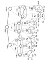
- FIG. 2 is a diagram illustrating a configuration of a communication system according to the present embodiment and a virtual network provided by the present embodiment.
- N1 to N19 represent communication nodes
- C1 to C7 represent control devices that control the communication nodes.
- Each control device sets a processing rule that defines a processing method for a packet belonging to a certain flow for a communication node that it controls.
- Each communication node holds the processing rules set by the control device in a table.
- Each communication node retrieves a processing rule corresponding to the received packet from the table, and executes processing of the received packet (packet transfer or the like) according to the corresponding processing rule.
- the communication node requests the control device to set the processing rule corresponding to the received packet.
- the control device centrally controls the communication nodes under its control.
- the communication system includes communication nodes N1 to N3, N4 to N5, N6 to N8, N9 to N11, N12 to N14, N15 to N16, N17 to N19, and control devices C1 to C7 for controlling them. And.
- the communication nodes are connected by links represented by solid lines, and are included in domains D1, D2, D3, D4, D5, D6, and D7, respectively. Domain boundaries are indicated by dashed lines in FIG.
- Domains D1-D3, D4-D5, and D6-D7 are included in higher domains D8, D9, and D10, respectively.
- Control of the upper domains D8, D9, D10 is performed by each control device (C1-C7) included in the lower domain.
- Each control device (C1-C7) virtualizes its own managed domain as a domain node included in the upper domain. That is, the domain node functions as a virtual node.
- the control device C1 virtualizes the domain D1 including the communication nodes N1 to N3 as the domain node DN1 of the higher domain D8. That is, the control device C1 virtualizes the domain D1 including the communication nodes N1 to N3 into one virtual communication node (DN1).
- Domain nodes DN1 to DN10 correspond to domains D1 to D10, respectively.
- Virtualization is performed by setting a processing rule for a communication node to transfer a packet to a link (egress link) corresponding to the exit of each domain.
- the egress link is a link connecting the communication nodes N3 and N4.
- a unique identifier is assigned as a virtual port number of the domain node for each egress link of the domain.
- each communication node belonging to the domain node transfers the packet toward an egress link according to a processing rule corresponding to the identifier of the virtual port. Therefore, the packet is virtually transferred from the virtual port of the domain node.
- the control device virtualizes the domain communication node into a virtual communication node (domain node). Therefore, the domain's egress link corresponds to a virtual port in the domain node. Domain nodes configured by virtualization perform communication between domain nodes by transferring packets to this virtual port. Actually, the communication node corresponding to each domain node transfers the packet, but the control device virtualizes the packet transfer by the communication node to the packet transfer by the domain node.
- the control device uses the processing rule to virtualize the packet transfer by the communication node to the packet transfer by the domain node.
- the control device sets a processing rule that specifies the process of transferring the packet toward the domain's egress link to the communication node under its control. To do.
- FIG. 3 shows two types of processing rule tables to be set for the communication node included in the domain for virtualization to the domain node.
- the processing rule table A represents a processing rule set for a communication node that does not have a domain egress link.
- the processing rule table B represents a processing rule set for a communication node having a domain egress link.
- the identifier column is a series of identifiers stored in the header of the packet received by the communication node and associated with the processing rule.
- the hop counter is a counter used to identify an identifier to be referred to from among identifier strings stored in the header of a packet received by the communication node. The identifier and the hop counter are combined as a matching condition with the packet header.
- the communication node processes the packet according to the entry in the first column of the processing rule table A.
- the content stored in the “process” field is a process executed by the communication node on the received packet when the header of the received packet matches the matching condition.
- the identifier specifying means in the communication node is a hop counter, but other means such as not always mounting the hop counter but always referring to the head identifier and deleting the referenced identifier.
- the communication node to which the processing rule of the processing rule table A is set is a communication node that does not have an egress link.
- the processing rule of the processing rule table A is a rule for executing a process of outputting to a port number toward the domain egress link when a packet including the virtual port number 50 in the processing rule sequence in the packet header is input to the communication node. Become.
- the port number described in the processing field of FIG. 3 differs depending on the communication node, and represents an output port used for transfer from each communication node to the egress link.
- the communication node to which the processing rule of the processing rule table B is set is a communication node having an egress link.
- the hop counter is incremented and then output to the egress link. With this process, a packet that has reached the communication node that is the output destination of the egress link is processed with reference to the next identifier.
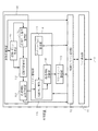
- FIG. 4 is a block diagram illustrating the configuration of the control device as an example.
- the control device includes a node communication unit 11, a control message processing unit 12, a flow entry management unit 13, a domain management unit 14, and a virtualization management unit 15.
- the node communication unit 11 communicates with a communication node.
- the control device may communicate with another control device when performing virtualization.
- the control device communicates with another control device using the node communication unit 11.
- the control message processing unit 12 converts the control content to the communication node as a control message, or analyzes and processes the control message from the communication node.
- the flow entry management unit 13 generates and manages processing rules related to packet transfer in the communication node.
- the domain management unit 14 controls a domain managed by itself.
- the virtualization manager 15 controls a plurality of lower domains as one upper domain node.
- the domain management unit 14 includes a domain topology management unit 141, a path tree calculation unit 142, and a processing rule calculation unit 143.
- the domain topology management unit 141 manages the topology information of the lowest-order domains D1 to D7 (that is, domains composed of communication nodes).
- the route tree calculation unit 142 calculates a route in each lowest domain, that is, a route toward the communication node corresponding to the egress link based on the topology of the lowest domain.
- the processing rule calculation unit 143 generates a processing rule from the calculation result of the route tree calculation unit 142.
- the virtualization management unit 15 includes a virtual topology management unit 151, a virtual port number management unit 152, a path tree calculation unit 153, and a processing rule setting request unit 154.
- the virtual topology management unit 151 manages a virtual topology composed of a virtual domain in each hierarchy or a connection relationship between domain nodes.
- the virtual port number management unit 152 allocates a virtual port number to a link port connected to another domain node.
- the virtual port number management unit 152 has a database for allocating virtual port numbers.
- the route tree calculation unit 153 calculates a route toward a domain node corresponding to a route in the domain, that is, a domain egress link port connected to another domain.
- the above domain egress link port represents a virtual port of a domain node corresponding to a link serving as an exit to another domain among domain nodes in the domain.
- the processing rule setting request unit 154 sets the processing rule according to the virtual port number designated by the virtual port number management unit 152 and the path tree calculated by the path tree calculation unit 153 corresponding thereto. 14
- the control device sets a processing rule in the communication node based on the calculation results of the path tree calculation units 142 and 153. This operation is executed, for example, when the communication system is initialized.
- the control device sets a processing rule corresponding to each domain constructed by virtualizing the network hierarchically in the communication node. Therefore, after setting the processing rules, the processing device only needs to calculate the route for packet transfer based on the topology of the virtualized domain. Since the topology based on the virtualized domain has fewer hops and management entities than the topology configured by communication nodes, the load of route calculation is reduced. Further, since the virtualized topology has a smaller number of pops than the topology by the communication node, the number of route setting inquiries to the control device during the packet transfer can be reduced. Furthermore, since the control device can control the packet transfer path according to a multi-layer topology, it can flexibly control the granularity of the transfer path.
- control device virtualizes a communication node and constructs a virtual network.
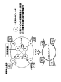
- FIG. 5 shows an operation example in which the control device virtualizes a domain composed of communication nodes into a domain node.
- N # 1 to N # 8 belong to domains under the control device.
- “E” is assigned as a prefix of N # 1 to N # 4. This “E” means a communication node corresponding to the external link of the domain.
- the external link indicates that the domain is a link connecting to another domain, that is, an egress link.
- the communication nodes N # 1 to N # 8 are used for explaining an operation example, and are not related to the communication nodes N1 to N19 shown in FIG.
- Numerals enclosed with squares are virtual port numbers assigned to domain nodes. The other numbers are port numbers of the communication node N # 1.
- the control device that controls the communication nodes in the domain virtualizes the domain composed of the communication nodes N # 1 to N # 8, and generates a domain node having virtual port numbers 32 to 35. .
- this operation will be described in detail.
- the virtual topology management unit 151 searches for a link (external link) used for connection to another domain and its port in the domain to be virtualized.
- the searched external link and port correspond to the link and port of the domain node generated by virtualizing the domain.
- the virtual topology management unit 151 recognizes the link of each communication node of the communication nodes EN # 1 to EN # 4 as an external link.
- the virtual port number management unit 152 newly assigns a virtual port number to the searched external link.
- the virtual port number management unit 152 searches for a new virtual port number from the port number DB.
- the port number DB may be content shared between other domains. In this case, a shared port number DB is formed by exchanging information between the control devices that manage the respective domains. This virtual port number becomes the virtual port number of the domain node generated by virtualization.
- the virtual port number management unit 152 is assigned from an unused virtual port number in order to assign a unique virtual port number.
- the route tree calculation unit 153 calculates a route based on a domain node belonging to the virtualized domain in order to realize packet transfer by the domain node generated by virtualization.
- the route calculation by the route tree calculation unit 153 will be described with reference to FIG.
- the path tree calculation unit 153 performs calculation so that the communication node N # 1 corresponding to the egress link to which the virtual port number “32” is assigned becomes the root of the path tree.
- the virtual port number “32” is assigned to the link corresponding to N # 1, and as shown in FIG. 6, the leaf node (N # 2, N # 3, N # 4) to the root node (N #)
- the upstream path tree towards 1) is calculated.
- the processing rule setting request unit 154 requests the domain management unit 14 to set a processing rule for the communication node based on the result calculated by the route tree calculation unit 153.
- the domain management unit 14 sets a processing rule for the communication node. For example, based on the calculation result of the path tree calculation unit 153, a processing rule that specifies that a packet whose identifier indicates the virtual port number “32” is transferred to the port 3 is set for N # 2. The domain management unit 14 sets a processing rule that stipulates that a packet whose identifier indicates the virtual port number “32” is transferred to the port 4 for N # 6. The domain management unit 14 sets a processing rule that stipulates that a packet whose identifier indicates the virtual port number “32” is transferred to the port 5 for N # 5.
- the domain management unit 14 transfers a packet whose identifier indicates the virtual port number “32” to the port 5 for EN # 1 corresponding to the external link, and increments the counter value stored in the packet.
- the domain management unit 14 executes the setting of the processing rule corresponding to the virtual port number “32” for the other communication nodes in the domain in the same procedure. Further, the domain management unit 14 executes processing rule settings corresponding to the other virtual port numbers “33” to “35” for the communication nodes in the domain in the same procedure.
- control device virtualizes the communication node of the domain and generates a domain node.
- one domain node becomes the representative domain node, and the generation process of the upper domain node is executed.
- the domain node 8 is a representative domain node. Note that the representative domain node may not be selected, and the control device corresponding to each domain node may cooperate to execute the generation process of the upper domain node.
- the operations by the virtual topology management unit 151, the virtual port number management unit 152, and the path tree calculation unit 153 of the representative domain node control device are the same as those described with reference to FIG. 5 and FIG. To do.
- the virtual port number assigned by the virtual port number management unit 152 uses a port number unique to all domain nodes belonging to this domain.
- the route tree calculation unit 153 calculates each route to each external link (link to which virtual port numbers “40” to “43” in FIG. 7 are assigned). Further, the virtual port number of each domain node corresponding to each route reaching each external link is detected from the route calculated by the route tree calculation unit 153. As shown in FIG. 8, the control device of the representative domain node 8 calculates the route corresponding to the detected virtual port number and the calculated route with respect to the control device corresponding to the other domain node. Requests setting of processing rules (broken arrows in FIG. 8).
- the packet to be output from the external link of the virtual port number “40” is the virtual port number 30 of the domain node 2, the virtual port number 36 of the domain node 6, and the virtual port 32 of the domain node 5.
- the virtual port 31 of the domain node 1 are transferred in this order.
- the control device of the representative domain node 8 requests the control device corresponding to the domain node 2 to calculate the route reaching the virtual port 30 in the route in the domain to which the domain node 2 belongs.
- the route calculation by the control device of the domain node 2 is the same as the method described with reference to FIGS.
- the control device corresponding to the domain node 2 sets the processing rule corresponding to the calculated route in each communication node in association with the virtual port number “40”.
- the control device corresponding to the domain node 2 sets a processing rule to be executed for a packet corresponding to the virtual port number “40” in each communication node.
- the virtual port number “40” is the virtual port number of the upper domain node generated by virtualization. Therefore, the communication node in the domain to which the domain node 2 belongs can execute an operation corresponding to the virtual boat number “40” of the higher domain node.
- the control device of the representative domain node 8 makes a similar request to the control devices of other domain nodes. Upon receiving the request, the control device sets processing rules corresponding to the virtual port numbers “40” to “43” of the upper domain node for the communication node.
- one domain node becomes the representative upper domain node, and the second higher domain node is generated.
- the domain node 8 becomes the representative upper domain node.
- the representative upper domain node may not be selected, and the control devices corresponding to the respective domain nodes may cooperate to execute the generation process of the second upper domain node.
- the control device of the representative higher domain node 8 virtualizes the domain A and generates a second higher domain node having virtual port numbers “50” to “53”.
- the route tree calculation unit 153 calculates each route that reaches each external link of the domain A (links with virtual port numbers “50” to “53” in FIG. 9). Further, the path tree calculation unit 153 also detects the virtual port number of each upper domain node corresponding to each path reaching each external link.
- the control device of the representative upper domain node 8 requests the control device corresponding to the other domain node to calculate the detected virtual port number of the upper domain node and the route corresponding to the virtual port number.
- Each upper domain node can be controlled by a single control device or by a plurality of control devices. When the upper domain node is controlled by a plurality of control devices, the control device of the representative higher domain node 8 sends a request to the plurality of control devices.
- FIG. 9 shows an example in which the control device of the representative higher domain node 8 makes a request to the control device of the higher domain node 6.
- the operation that the control device of the representative upper domain node 8 requests to other upper domain nodes is omitted.
- the control device of the representative upper domain node 8 sends a request to the upper domain node 6 will be described as an example.
- the control device of the representative higher domain node 8 sends a request similar to the following description to the control devices corresponding to the other higher domain nodes. This request is sent for each virtual port number “50” to “53” of the second upper domain node generated by virtualization.
- the control device of the representative upper domain node 8 calculates that the virtual port number of the upper domain node corresponding to the route to the virtual port number “50” of the second upper domain node generated by virtualization is “42”. To do.
- the control device of the representative domain node 8 sends the calculation of the route corresponding to the virtual port number “42” to the control device corresponding to the upper domain node 6.
- the control device corresponding to the upper domain node 6 that has received the request recognizes that the upper domain node 6 is generated by virtualizing the domain B to which the domain node 1-4 belongs. Therefore, the control device recognizes that the domain B is configured by a virtual domain node and not a domain configured by a communication node. In this case, the control device does not set the processing rule corresponding to the request from the control device of the representative upper domain node 8 in the communication node, and sends a processing rule setting request to the lower layer control device.
- the control device corresponding to the representative domain node 2 calculates a route to the virtual port number “42” corresponding to the external link of the domain B. Since the route calculation method is the same as the method described with reference to FIGS. 5 and 6, the description thereof is omitted.
- the control device of the representative domain node 2 detects the virtual port number of each domain node corresponding to the path to the virtual port number “42”.
- the control device of the representative domain node 2 requests the control device corresponding to the other domain node to calculate the detected virtual port number of each domain node and the route corresponding to the virtual port number.
- the control device of the representative domain node 2 detects that the virtual port number “32” of the domain node 3 is a virtual port corresponding to the route to the virtual port number “42”.
- the control device of the representative domain node 2 requests the control device corresponding to the domain node 3 to calculate a virtual port number of the detected domain node and a route corresponding to the virtual port number.
- the control device of the representative domain node 2 sends out this request including the virtual port number “50” of the second higher domain node.
- the control device of the domain node 3 When the control device of the domain node 3 receives the request, it calculates a route corresponding to the virtual port number “32”. Since the route calculation method is the same as the method described with reference to FIGS. 5 and 6, the description thereof is omitted.
- the control device of the domain node 3 recognizes that the domain node 3 is generated by virtualizing the communication nodes N # 1 to N # 3. Therefore, the control device of the domain node 3 detects the port number of the communication node corresponding to the calculated route, calculates the processing rule based on the detected port number, and sets it for each communication node.
- the control device of the domain node 3 sets the processing rule to be set for the communication node in association with the virtual port number “50” of the second higher domain node. For example, in FIG.
- the control device sets a processing rule that stipulates that a packet corresponding to the virtual port number “50” is transmitted from port 5 in N # 3.
- the control device specifies that EN # 1 sends a packet corresponding to the virtual port number “50” from port 3 and increments (or decrements) the counter value stored in the packet.
- Set rules By setting a processing rule corresponding to the virtual port number of the second upper domain node in each communication node, the virtual operation by the second upper domain node can be realized by the operation of the communication node.
- the processing device calculates a packet transfer route based on a virtualized network topology as a packet transfer route. Since the topology of a virtualized network has fewer hops and management entities than the topology constituted by communication nodes, the load of route calculation is reduced. Note that the topology of the network virtualized in multiple layers is shared by, for example, a plurality of control devices, and each control device can calculate a packet path based on the topology of the network virtualized in multiple layers. In addition, the control device that supervises a plurality of control devices manages the topology of the network virtualized in multiple layers, calculates the route of the packet based on the topology information, and calculates the route for each control device. May support packet forwarding.
- P50, P51, and P35 display a part of the virtual port number assigned as the output port of the domain node, and P3 and P1 display a part of the actual port number of the communication node. It is.
- the communication system in FIG. 10 is virtualized into a three-layer network.
- Host1 and host2 indicate hosts that perform communication.
- the packet When a packet is transmitted from host1 to host2, the packet is input to communication node N1.
- the communication node N1 inquires of the control device C1 about an identifier to be added to the packet.
- the communication node inquires the identifier to be added to the packet to the control device and the communication node adds the identifier to the packet will be described.
- a method may be employed in which the host inquires of one of the control devices C1 to C7 about the identifier to be added to the packet.
- the host may obtain the topology from any one of the control devices C1 to C7, calculate the route according to its own policy, and calculate the identifier.
- a server for notifying the host of the identifier may be provided.
- control device When the control device receives the inquiry, it calculates a route used for communication using a three-layer topology. At this time, the topology hierarchy used for calculation can be selected for each hop, and flexible route selection is possible.
- the control device calculates an identifier to be added to the packet based on the calculated route.
- This identifier is an output port in each hierarchical node.
- the communication node N1 adds an identifier received from the control device to the packet, and searches for a processing rule corresponding to the identifier. Based on the processing rule corresponding to the identifier, the communication node N1 transfers the packet to the communication node N3.
- an identifier column is embedded in a packet header, and an identifier to be used for each hop is specified by holding a hop counter.
- a method of deleting the used identifier from the head without using the hop counter can be adopted.
- the identifier to be referred to in the communication node N1 is 50, and this indicates an output port in the node of the highest hierarchy.
- a processing rule corresponding to the identifier 50 has already been set in the communication node included in DN8.
- the processing rules at the communication nodes N1, N3, N4, and N5 that have received the packet are the same as those in the processing rule table A of FIG. 3, and the packet is transferred while continuing to refer to the identifier 50 in the packet.
- the processing rule is the same as that in the processing rule table B of FIG. 3. After adding the hop counter, the processing rule is output to the link from N7 to N9 which is a real port corresponding to the port 50 in DN8.
- the head identifier 50 included in the packet is used to output to the egress link of DN8.
- the identifier to be referred to is 51.
- the transfer is continued until N15 is reached, and the hop counter is added.
- the identifier referred to by the communication node N15 is 35, which represents the node in the second highest hierarchy, and the port 35 in DN6. In this case, transfer is performed until the communication node N17 is reached, and a hop counter is added at the time of the final transfer.
- the identifier referred to by the communication node N17 is 3, which indicates the actual port number of the communication node. Therefore, it is transferred to the communication node N19 which is the next hop at the lowest layer, and the hop counter is added.
- the identifier referred to by the communication node N19 is 1, which is similarly transferred to the next hop and transferred to host2.
- the packet is transferred through the virtualized network.
- packet transfer is performed by adding identifiers for each layer of hops to a packet, and the number of identifiers to be added can be reduced.
Abstract
Description
本発明は、日本国特許出願:特願2011-024045号(2011年2月7日出願)の優先権主張に基づくものであり、同出願の全記載内容は引用をもって本書に組み込み記載されているものとする。
本発明は、通信システム、制御装置、通信ノードおよび通信方法に関し、特に、ネットワーク上のノードを仮想化してパケットを転送する通信システム、かかる通信システムにおける通信を制御する制御装置、通信ノードおよび、通信方法に関する。 [Description of related applications]
The present invention is based on the priority claim of Japanese Patent Application No. 2011-024405 (filed on Feb. 7, 2011), the entire contents of which are incorporated herein by reference. Shall.
The present invention relates to a communication system, a control device, a communication node, and a communication method, and in particular, a communication system that virtualizes nodes on a network and transfers packets, a control device that controls communication in such a communication system, a communication node, and a communication Regarding the method.
複数の通信ノードと、
前記複数の通信ノードのパケット処理を制御する制御装置と、を備え、
前記制御装置は、前記複数の通信ノードのうちの複数の通信ノードから仮想ノードを構成する仮想化部と、
前記仮想ノードに含まれる複数の通信ノードの少なくとも1つの通信ノードが前記仮想ノードの動作に対応するパケット処理を実行するように、該少なくとも1つの通信ノードに対してパケットの処理規則を設定する制御部と、
前記仮想ノードで構成される仮想ネットワークトポロジに基づいて、パケットの転送経路を計算する経路計算部と、をさらに備え、
前記複数の通信ノードは、それぞれ、前記処理規則に従って、前記転送経路に対応するパケットを処理する。 The communication system according to the first aspect of the present invention is:
Multiple communication nodes;
A control device for controlling packet processing of the plurality of communication nodes,
The control device includes a virtualization unit that configures a virtual node from a plurality of communication nodes among the plurality of communication nodes;
Control for setting a packet processing rule for at least one communication node so that at least one communication node of the plurality of communication nodes included in the virtual node executes packet processing corresponding to the operation of the virtual node And
A route calculation unit that calculates a packet transfer route based on a virtual network topology composed of the virtual nodes; and
Each of the plurality of communication nodes processes a packet corresponding to the transfer path according to the processing rule.
複数の通信ノードのパケット処理を制御する制御装置であって、
前記複数の通信ノードのうちの複数の通信ノードから仮想ノードを構成する仮想化部と、
前記仮想ノードに含まれる複数の通信ノードの少なくとも1つの通信ノードが前記仮想ノードの動作に対応するパケット処理を実行するように、該少なくとも1つの通信ノードに対してパケットの処理規則を設定する制御部と、
前記仮想ノードで構成される仮想ネットワークトポロジに基づいて、パケットの転送経路を計算する経路計算部と、を備えている。 The control device according to the second aspect of the present invention is:
A control device that controls packet processing of a plurality of communication nodes,
A virtualization unit constituting a virtual node from a plurality of communication nodes of the plurality of communication nodes;
Control for setting a packet processing rule for at least one communication node so that at least one communication node of the plurality of communication nodes included in the virtual node executes packet processing corresponding to the operation of the virtual node And
A route calculation unit that calculates a packet transfer route based on a virtual network topology constituted by the virtual nodes.
複数の通信ノードのパケット処理を制御する制御装置が、該複数の通信ノードのうちの複数の通信ノードから仮想ノードを構成する工程と、
前記仮想ノードに含まれる複数の通信ノードの少なくとも1つの通信ノードが前記仮想ノードの動作に対応するパケット処理を実行するように、該少なくとも1つの通信ノードに対してパケットの処理規則を設定する工程と、
前記仮想ノードで構成される仮想ネットワークトポロジに基づいて、パケットの転送経路を計算する工程と、を含む。 The communication method according to the third aspect of the present invention is:
A control device for controlling packet processing of a plurality of communication nodes, forming a virtual node from a plurality of communication nodes of the plurality of communication nodes;
Setting a packet processing rule for the at least one communication node so that at least one communication node of the plurality of communication nodes included in the virtual node executes packet processing corresponding to the operation of the virtual node. When,
Calculating a packet forwarding path based on a virtual network topology composed of the virtual nodes.
複数の通信ノードのパケット処理を制御する制御装置を備えた通信システムにおける該複数の通信ノードのうちの1つの通信ノードであって、
前記制御装置は、前記複数の通信ノードのうちの複数の通信ノードから仮想ノードを構成する仮想化部と、
前記仮想ノードに含まれる複数の通信ノードの少なくとも1つの通信ノードが前記仮想ノードの動作に対応するパケット処理を実行するように、該少なくとも1つの通信ノードに対してパケットの処理規則を設定する制御部と、
前記仮想ノードで構成される仮想ネットワークトポロジに基づいて、パケットの転送経路を計算する経路計算部と、をさらに備え、
前記処理規則に従って、前記転送経路に対応するパケットを処理する。 The communication node according to the fourth aspect of the present invention is:
A communication node of the plurality of communication nodes in a communication system including a control device that controls packet processing of the plurality of communication nodes,
The control device includes a virtualization unit that configures a virtual node from a plurality of communication nodes among the plurality of communication nodes;
Control for setting a packet processing rule for at least one communication node so that at least one communication node of the plurality of communication nodes included in the virtual node executes packet processing corresponding to the operation of the virtual node And
A route calculation unit that calculates a packet transfer route based on a virtual network topology composed of the virtual nodes; and
A packet corresponding to the transfer path is processed according to the processing rule.
[形態1]
上記第1の視点に係る通信システムのとおりである。
[形態2]
前記制御部は、前記仮想ノードの仮想ポートに対応する通信ノードにパケットが転送されるように、前記仮想ノードに含まれる複数の通信ノードの少なくとも1つに対して前記処理規則を設定するようにしてもよい。
[形態3]
前記制御部は、前記処理規則を、前記仮想ノードの仮想ポートを表す識別子と対応付けて、前記仮想ノードに含まれる複数の通信ノードの少なくとも1つに対して設定するようにしてもよい。
[形態4]
前記複数の通信ノードは、それぞれ、前記識別子に対応するパケットを受信した場合、前記識別子と対応付けられた処理規則に従って該パケットを処理するようにしてもよい。
[形態5]
前記複数の通信ノードは、それぞれ、前記識別子を格納したパケットを受信した場合、前記識別子と対応付けられた処理規則に従って該パケットを処理するようにしてもよい。
[形態6]
前記仮想ポートに対応する通信ノードは、前記識別子を格納したパケットを処理する際、前記識別子が他の通信ノードで参照されないように該パケットを処理するようにしてもよい。
[形態7]
上記第2の視点に係る制御装置のとおりである。
[形態8]
前記制御部は、前記仮想ノードの仮想ポートに対応する通信ノードにパケットが転送されるように、前記仮想ノードに含まれる複数の通信ノードの少なくとも1つに対して前記処理規則を設定するようにしてもよい。
[形態9]
前記制御部は、前記処理規則を、前記仮想ノードの仮想ポートを表す識別子と対応付けて、前記仮想ノードに含まれる複数の通信ノードの少なくとも1つに対して設定するようにしてもよい。
[形態10]
上記第3の視点に係る通信方法のとおりである。
[形態11]
前記複数の通信ノードが、それぞれ、前記処理規則に従って、前記転送経路に対応するパケットを処理する工程を含んでいてもよい。
[形態12]
前記制御装置が、前記仮想ノードの仮想ポートに対応する通信ノードにパケットが転送されるように、前記仮想ノードに含まれる複数の通信ノードの少なくとも1つに対して前記処理規則を設定する工程を含んでいてもよい。
[形態13]
前記制御装置が、前記処理規則を、前記仮想ノードの仮想ポートを表す識別子と対応付けて、前記仮想ノードに含まれる複数の通信ノードの少なくとも1つに対して設定する工程を含んでいてもよい。
[形態14]
前記複数の通信ノードが、前記識別子に対応するパケットを受信した場合、前記識別子と対応付けられた処理規則に従って該パケットを処理する工程を含んでいてもよい。
[形態15]
前記複数の通信ノードが、前記識別子を格納したパケットを受信した場合、前記識別子と対応付けられた処理規則に従って該パケットを処理する工程を含んでいてもよい。
[形態16]
前記仮想ポートに対応する通信ノードにおいて、前記識別子を格納したパケットを処理する際、前記識別子が他の通信ノードで参照されないように該パケットを処理する工程を含んでいてもよい。 In the present invention, the following modes are possible.
[Form 1]
The communication system according to the first aspect is as described above.
[Form 2]
The control unit sets the processing rule for at least one of a plurality of communication nodes included in the virtual node so that a packet is transferred to the communication node corresponding to the virtual port of the virtual node. May be.
[Form 3]
The control unit may set the processing rule for at least one of a plurality of communication nodes included in the virtual node in association with an identifier representing a virtual port of the virtual node.
[Form 4]
When each of the plurality of communication nodes receives a packet corresponding to the identifier, the plurality of communication nodes may process the packet according to a processing rule associated with the identifier.
[Form 5]
When each of the plurality of communication nodes receives a packet storing the identifier, each of the plurality of communication nodes may process the packet according to a processing rule associated with the identifier.
[Form 6]
When the communication node corresponding to the virtual port processes the packet storing the identifier, the communication node may process the packet so that the identifier is not referred to by another communication node.
[Form 7]
As in the control device according to the second aspect.
[Form 8]
The control unit sets the processing rule for at least one of a plurality of communication nodes included in the virtual node so that a packet is transferred to the communication node corresponding to the virtual port of the virtual node. May be.
[Form 9]
The control unit may set the processing rule for at least one of a plurality of communication nodes included in the virtual node in association with an identifier representing a virtual port of the virtual node.
[Mode 10]
The communication method according to the third viewpoint is as described above.
[Form 11]
Each of the plurality of communication nodes may include a step of processing a packet corresponding to the transfer path according to the processing rule.
[Form 12]
A step in which the control device sets the processing rule for at least one of a plurality of communication nodes included in the virtual node such that a packet is transferred to the communication node corresponding to the virtual port of the virtual node; May be included.
[Form 13]
The control apparatus may include a step of setting the processing rule in association with an identifier representing a virtual port of the virtual node for at least one of a plurality of communication nodes included in the virtual node. .
[Form 14]
When the plurality of communication nodes receive a packet corresponding to the identifier, the communication node may include a step of processing the packet according to a processing rule associated with the identifier.
[Form 15]
The plurality of communication nodes may include a step of processing the packet in accordance with a processing rule associated with the identifier when the packet storing the identifier is received.
[Form 16]
The communication node corresponding to the virtual port may include a step of processing the packet so that the identifier is not referred to by another communication node when the packet storing the identifier is processed.
実施形態に係る通信システムについて、図面を参照して説明する。図2は、本実施形態に係る通信システムの構成と本実施形態により提供される仮想ネットワークを示す図である。 (Embodiment)
A communication system according to an embodiment will be described with reference to the drawings. FIG. 2 is a diagram illustrating a configuration of a communication system according to the present embodiment and a virtual network provided by the present embodiment.
10 制御装置
11 ノード通信部
12 制御メッセージ処理部
13 フローエントリ管理部
14 ドメイン管理部
15 仮想化管理部
100 仮想ノード
141 ドメイントポロジ管理部
142 経路木計算部
143 処理規則計算部
151 仮想トポロジ管理部
152 仮想ポート番号管理部
153 経路木計算部
154 処理規則設定依頼部
C1~C7 制御装置
D1~D10 ドメイン
DN1~DN10 ドメインノード
N1~N19 通信ノード
P1,P3 実ポート番号の一部
P35,P50,P51 仮想ポート番号の一部 1 to 3
Claims (17)
- 複数の通信ノードと、
前記複数の通信ノードのパケット処理を制御する制御装置と、を備え、
前記制御装置は、前記複数の通信ノードのうちの複数の通信ノードから仮想ノードを構成する仮想化部と、
前記仮想ノードに含まれる複数の通信ノードの少なくとも1つの通信ノードが前記仮想ノードの動作に対応するパケット処理を実行するように、該少なくとも1つの通信ノードに対してパケットの処理規則を設定する制御部と、
前記仮想ノードで構成される仮想ネットワークトポロジに基づいて、パケットの転送経路を計算する経路計算部と、をさらに備え、
前記複数の通信ノードは、それぞれ、前記処理規則に従って、前記転送経路に対応するパケットを処理することを特徴とする通信システム。 Multiple communication nodes;
A control device for controlling packet processing of the plurality of communication nodes,
The control device includes a virtualization unit that configures a virtual node from a plurality of communication nodes among the plurality of communication nodes;
Control for setting a packet processing rule for at least one communication node so that at least one communication node of the plurality of communication nodes included in the virtual node executes packet processing corresponding to the operation of the virtual node And
A route calculation unit that calculates a packet transfer route based on a virtual network topology composed of the virtual nodes; and
Each of the plurality of communication nodes processes a packet corresponding to the transfer path according to the processing rule. - 前記制御部は、前記仮想ノードの仮想ポートに対応する通信ノードにパケットが転送されるように、前記仮想ノードに含まれる複数の通信ノードの少なくとも1つに対して前記処理規則を設定することを特徴とする、請求項1に記載の通信システム。 The control unit sets the processing rule for at least one of a plurality of communication nodes included in the virtual node so that a packet is transferred to the communication node corresponding to the virtual port of the virtual node. The communication system according to claim 1, wherein the communication system is characterized.
- 前記制御部は、前記処理規則を、前記仮想ノードの仮想ポートを表す識別子と対応付けて、前記仮想ノードに含まれる複数の通信ノードの少なくとも1つに対して設定することを特徴とする、請求項1に記載の通信システム。 The control unit sets the processing rule for at least one of a plurality of communication nodes included in the virtual node in association with an identifier representing a virtual port of the virtual node. Item 12. The communication system according to Item 1.
- 前記複数の通信ノードは、それぞれ、前記識別子に対応するパケットを受信した場合、前記識別子と対応付けられた処理規則に従って該パケットを処理することを特徴とする、請求項3に記載の通信システム。 The communication system according to claim 3, wherein, when each of the plurality of communication nodes receives a packet corresponding to the identifier, the communication node processes the packet according to a processing rule associated with the identifier.
- 前記複数の通信ノードは、それぞれ、前記識別子を格納したパケットを受信した場合、前記識別子と対応付けられた処理規則に従って該パケットを処理することを特徴とする、請求項3に記載の通信システム。 The communication system according to claim 3, wherein each of the plurality of communication nodes processes the packet in accordance with a processing rule associated with the identifier when receiving the packet storing the identifier.
- 前記仮想ポートに対応する通信ノードは、前記識別子を格納したパケットを処理する際、前記識別子が他の通信ノードで参照されないように該パケットを処理することを特徴とする、請求項5に記載の通信システム。 The communication node corresponding to the virtual port processes the packet so that the identifier is not referred to by another communication node when processing the packet storing the identifier. Communications system.
- 前記仮想化部は、複数の前記仮想ノードのうちの複数の仮想ノードから上位仮想ノードを構成し、
前記制御部は、前記上位仮想ノードに含まれる複数の仮想ノードの少なくとも1つの仮想ノードが前記上位仮想ノードの動作に対応するパケット処理を実行するように、該少なくとも1つの仮想ノードに対してパケットの処理規則を設定し、
前記経路計算部は、前記上位仮想ノードで構成される上位仮想ネットワークトポロジに基づいて、パケットの転送経路を計算し、
前記複数の通信ノードは、それぞれ、前記処理規則に従って、前記転送経路に対応するパケットを処理することを特徴とする、請求項1ないし6のいずれか1項に記載の通信システム。 The virtualization unit configures an upper virtual node from a plurality of virtual nodes among the plurality of virtual nodes,
The control unit performs packet processing on the at least one virtual node so that at least one virtual node of the plurality of virtual nodes included in the upper virtual node performs packet processing corresponding to the operation of the upper virtual node. Set processing rules for
The route calculation unit calculates a packet transfer route based on an upper virtual network topology composed of the upper virtual nodes,
The communication system according to any one of claims 1 to 6, wherein each of the plurality of communication nodes processes a packet corresponding to the transfer path according to the processing rule. - 複数の通信ノードのパケット処理を制御する制御装置であって、
前記複数の通信ノードのうちの複数の通信ノードを含む仮想ノードを構成する仮想化部と、
前記仮想ノードに含まれる複数の通信ノードの少なくとも1つの通信ノードが前記仮想ノードの動作に対応するパケット処理を実行するように、該少なくとも1つの通信ノードに対してパケットの処理規則を設定する制御部と、
前記仮想ノードで構成される仮想ネットワークトポロジに基づいて、パケットの転送経路を計算する経路計算部と、を備えることを特徴とする制御装置。 A control device that controls packet processing of a plurality of communication nodes,
A virtualization unit constituting a virtual node including a plurality of communication nodes among the plurality of communication nodes;
Control for setting a packet processing rule for at least one communication node so that at least one communication node of the plurality of communication nodes included in the virtual node executes packet processing corresponding to the operation of the virtual node And
And a route calculation unit that calculates a packet transfer route based on a virtual network topology including the virtual nodes. - 前記制御部は、前記仮想ノードの仮想ポートに対応する通信ノードにパケットが転送されるように、前記仮想ノードに含まれる複数の通信ノードの少なくとも1つに対して前記処理規則を設定することを特徴とする、請求項8に記載の制御装置。 The control unit sets the processing rule for at least one of a plurality of communication nodes included in the virtual node so that a packet is transferred to the communication node corresponding to the virtual port of the virtual node. The control device according to claim 8, wherein the control device is characterized.
- 前記制御部は、前記処理規則を、前記仮想ノードの仮想ポートを表す識別子と対応付けて、前記仮想ノードに含まれる複数の通信ノードの少なくとも1つに対して設定することを特徴とする、請求項8に記載の制御装置。 The control unit sets the processing rule for at least one of a plurality of communication nodes included in the virtual node in association with an identifier representing a virtual port of the virtual node. Item 9. The control device according to Item 8.
- 前記仮想化部は、複数の前記仮想ノードのうちの複数の仮想ノードから上位仮想ノードを構成し、
前記制御部は、前記上位仮想ノードに含まれる複数の仮想ノードの少なくとも1つの仮想ノードが前記上位仮想ノードの動作に対応するパケット処理を実行するように、該少なくとも1つの仮想ノードに対してパケットの処理規則を設定し、
前記経路計算部は、前記上位仮想ノードで構成される上位仮想ネットワークトポロジに基づいて、パケットの転送経路を計算し、
前記複数の通信ノードは、それぞれ、前記処理規則に従って、前記転送経路に対応するパケットを処理することを特徴とする、請求項8ないし10のいずれか1項に記載の制御装置。 The virtualization unit configures an upper virtual node from a plurality of virtual nodes among the plurality of virtual nodes,
The control unit performs packet processing on the at least one virtual node so that at least one virtual node of the plurality of virtual nodes included in the upper virtual node performs packet processing corresponding to the operation of the upper virtual node. Set processing rules for
The route calculation unit calculates a packet transfer route based on an upper virtual network topology composed of the upper virtual nodes,
11. The control device according to claim 8, wherein each of the plurality of communication nodes processes a packet corresponding to the transfer path in accordance with the processing rule. - 複数の通信ノードのパケット処理を制御する制御装置が、該複数の通信ノードのうちの複数の通信ノードから仮想ノードを構成する工程と、
前記仮想ノードに含まれる複数の通信ノードの少なくとも1つの通信ノードが前記仮想ノードの動作に対応するパケット処理を実行するように、該少なくとも1つの通信ノードに対してパケットの処理規則を設定する工程と、
前記仮想ノードで構成される仮想ネットワークトポロジに基づいて、パケットの転送経路を計算する工程と、を含むことを特徴とする通信方法。 A control device for controlling packet processing of a plurality of communication nodes, forming a virtual node from a plurality of communication nodes of the plurality of communication nodes;
Setting a packet processing rule for the at least one communication node so that at least one communication node of the plurality of communication nodes included in the virtual node executes packet processing corresponding to the operation of the virtual node. When,
And a step of calculating a packet transfer path based on a virtual network topology constituted by the virtual nodes. - 前記制御装置が、前記仮想ノードの仮想ポートに対応する通信ノードにパケットが転送されるように、前記仮想ノードに含まれる複数の通信ノードの少なくとも1つに対して前記処理規則を設定することを特徴とする、請求項12に記載の通信方法。 The controller sets the processing rule for at least one of a plurality of communication nodes included in the virtual node so that a packet is forwarded to the communication node corresponding to the virtual port of the virtual node; The communication method according to claim 12, wherein the communication method is characterized.
- 前記制御装置が、前記処理規則を、前記仮想ノードの仮想ポートを表す識別子と対応付けて、前記仮想ノードに含まれる複数の通信ノードの少なくとも1つに対して設定することを特徴とする、請求項12に記載の通信方法。 The control device sets the processing rule for at least one of a plurality of communication nodes included in the virtual node in association with an identifier representing a virtual port of the virtual node. Item 13. The communication method according to Item 12.
- 前記制御装置が、複数の前記仮想ノードのうちの複数の仮想ノードから上位仮想ノードを構成する工程と、
前記上位仮想ノードに含まれる複数の仮想ノードの少なくとも1つの仮想ノードが前記上位仮想ノードの動作に対応するパケット処理を実行するように、該少なくとも1つの仮想ノードに対してパケットの処理規則を設定する工程と、
前記上位仮想ノードで構成される上位仮想ネットワークトポロジに基づいて、パケットの転送経路を計算する工程と、を含むことを特徴とする、請求項12ないし14のいずれか1項に記載の通信方法。 The controller configured to configure an upper virtual node from a plurality of virtual nodes of the plurality of virtual nodes;
A packet processing rule is set for at least one virtual node so that at least one virtual node of the plurality of virtual nodes included in the upper virtual node executes packet processing corresponding to the operation of the upper virtual node. And a process of
The communication method according to claim 12, further comprising: calculating a packet transfer route based on an upper virtual network topology including the upper virtual nodes. - 複数の通信ノードのパケット処理を制御する制御装置を備えた通信システムにおける該複数の通信ノードのうちの1つの通信ノードであって、
前記制御装置は、前記複数の通信ノードのうちの複数の通信ノードから仮想ノードを構成する仮想化部と、
前記仮想ノードに含まれる複数の通信ノードの少なくとも1つの通信ノードが前記仮想ノードの動作に対応するパケット処理を実行するように、該少なくとも1つの通信ノードに対してパケットの処理規則を設定する制御部と、
前記仮想ノードで構成される仮想ネットワークトポロジに基づいて、パケットの転送経路を計算する経路計算部と、をさらに備え、
前記処理規則に従って、前記転送経路に対応するパケットを処理することを特徴とする通信ノード。 A communication node of the plurality of communication nodes in a communication system including a control device that controls packet processing of the plurality of communication nodes,
The control device includes a virtualization unit that configures a virtual node from a plurality of communication nodes among the plurality of communication nodes;
Control for setting a packet processing rule for at least one communication node so that at least one communication node of the plurality of communication nodes included in the virtual node executes packet processing corresponding to the operation of the virtual node And
A route calculation unit that calculates a packet transfer route based on a virtual network topology composed of the virtual nodes; and
A communication node that processes a packet corresponding to the transfer path in accordance with the processing rule. - 前記制御装置は、前記処理規則を、前記仮想ノードの仮想ポートを表す識別子と対応付けて、前記仮想ノードに含まれる複数の通信ノードの少なくとも1つに対して設定し、
前記識別子に対応するパケットを受信した場合、前記識別子と対応付けられた処理規則に従って該パケットを処理することを特徴とする、請求項16に記載の通信ノード。 The control device associates the processing rule with an identifier representing a virtual port of the virtual node, and sets the processing rule for at least one of a plurality of communication nodes included in the virtual node;
The communication node according to claim 16, wherein when a packet corresponding to the identifier is received, the packet is processed according to a processing rule associated with the identifier.
Priority Applications (4)
| Application Number | Priority Date | Filing Date | Title |
|---|---|---|---|
| JP2012556873A JP5900353B2 (en) | 2011-02-07 | 2012-02-06 | COMMUNICATION SYSTEM, CONTROL DEVICE, COMMUNICATION NODE, AND COMMUNICATION METHOD |
| US13/983,539 US9246814B2 (en) | 2011-02-07 | 2012-02-06 | Communication system, control apparatus, communication node, and communication method |
| CN201280007974.1A CN103348638B (en) | 2011-02-07 | 2012-02-06 | Communication system, control device, communication node and communication means |
| EP12745132.6A EP2675119B1 (en) | 2011-02-07 | 2012-02-06 | Communication system, control device, communication node, and communication method |
Applications Claiming Priority (2)
| Application Number | Priority Date | Filing Date | Title |
|---|---|---|---|
| JP2011024045 | 2011-02-07 | ||
| JP2011-024045 | 2011-02-07 |
Publications (1)
| Publication Number | Publication Date |
|---|---|
| WO2012108382A1 true WO2012108382A1 (en) | 2012-08-16 |
Family
ID=46638597
Family Applications (1)
| Application Number | Title | Priority Date | Filing Date |
|---|---|---|---|
| PCT/JP2012/052612 WO2012108382A1 (en) | 2011-02-07 | 2012-02-06 | Communication system, control device, communication node, and communication method |
Country Status (5)
| Country | Link |
|---|---|
| US (1) | US9246814B2 (en) |
| EP (1) | EP2675119B1 (en) |
| JP (1) | JP5900353B2 (en) |
| CN (1) | CN103348638B (en) |
| WO (1) | WO2012108382A1 (en) |
Cited By (7)
| Publication number | Priority date | Publication date | Assignee | Title |
|---|---|---|---|---|
| WO2015079615A1 (en) * | 2013-11-27 | 2015-06-04 | 日本電気株式会社 | Communication system, communication method, network information combination apparatus, processing rule conversion method, and processing rule conversion program |
| JP2016192660A (en) * | 2015-03-31 | 2016-11-10 | 日本電気株式会社 | Network system, network control method, control device, and operation management device |
| JP2016192661A (en) * | 2015-03-31 | 2016-11-10 | 日本電気株式会社 | Network system, network control method, and control device |
| EP2981035A4 (en) * | 2013-03-29 | 2016-11-30 | Nec Corp | Control apparatus, communication system, communication node control method and program |
| JP2017504265A (en) * | 2014-01-10 | 2017-02-02 | ホアウェイ・テクノロジーズ・カンパニー・リミテッド | System and method for zoning in a software defined network |
| JP2017147597A (en) * | 2016-02-17 | 2017-08-24 | 株式会社Nttドコモ | Communication device, route management server, communication method, and virtual port assignment method |
| US10257120B2 (en) | 2014-07-16 | 2019-04-09 | Nec Corporation | Converting an aggregated flow to a real flow for core nodes |
Families Citing this family (10)
| Publication number | Priority date | Publication date | Assignee | Title |
|---|---|---|---|---|
| US9769061B2 (en) * | 2012-05-23 | 2017-09-19 | Brocade Communications Systems, Inc. | Integrated heterogeneous software-defined network |
| KR20150000324A (en) * | 2013-06-24 | 2015-01-02 | 한국전자통신연구원 | Method and apparatus for routing |
| US9231877B2 (en) * | 2013-09-17 | 2016-01-05 | Adva Optical Networking Se | Method and apparatus for scaling traffic engineering routing in a network |
| EP3043515B1 (en) | 2013-10-18 | 2020-02-26 | Huawei Technologies Co., Ltd. | Method, controller, forwarding device, and network system for forwarding packets |
| EP3059909B1 (en) | 2013-11-22 | 2018-03-21 | Huawei Technologies Co., Ltd. | Method, apparatus and system for controlling forwarding of service data in virtual network |
| JP6292292B2 (en) * | 2014-03-25 | 2018-03-14 | 日本電気株式会社 | Communication node, control apparatus, communication system, communication method, and program |
| CN106803807B (en) * | 2016-12-15 | 2020-05-05 | 华南师范大学 | SDN network independent forwarding method based on multidimensional space superposition model |
| JP6567214B2 (en) * | 2017-02-28 | 2019-08-28 | 三菱電機株式会社 | Wireless communication apparatus, wireless communication method, and wireless communication program |
| CN108650333B (en) * | 2018-07-31 | 2021-02-02 | 泰链(厦门)科技有限公司 | Method, medium, device and system for distributing node load in block chain system |
| CN115348111B (en) * | 2022-10-18 | 2022-12-09 | 中国人民解放军军事科学院系统工程研究院 | Centralized connection control method for high-security network |
Citations (5)
| Publication number | Priority date | Publication date | Assignee | Title |
|---|---|---|---|---|
| JP2004129135A (en) * | 2002-10-07 | 2004-04-22 | Nippon Telegr & Teleph Corp <Ntt> | Hierarchized network node and network constructed by the node |
| JP2004140776A (en) * | 2002-07-12 | 2004-05-13 | Nec Corp | Frame transfer method for network and frame transfer program |
| JP2008211550A (en) * | 2007-02-27 | 2008-09-11 | Nippon Telegr & Teleph Corp <Ntt> | Data transfer method in mpls network, edge router, as boundary router, and program |
| JP2009539156A (en) | 2006-06-02 | 2009-11-12 | ホアウェイ・テクノロジーズ・カンパニー・リミテッド | Multi-domain route calculation method and system |
| WO2010103909A1 (en) * | 2009-03-09 | 2010-09-16 | 日本電気株式会社 | OpenFlow COMMUNICATION SYSTEM AND OpenFlow COMMUNICATION METHOD |
Family Cites Families (10)
| Publication number | Priority date | Publication date | Assignee | Title |
|---|---|---|---|---|
| JP2985940B2 (en) * | 1996-11-08 | 1999-12-06 | 日本電気株式会社 | Failure recovery device |
| CN100459534C (en) * | 2002-10-07 | 2009-02-04 | 日本电信电话株式会社 | Layer network node and network constituted throuth said nodes, the node and layer network thereof |
| GB0306855D0 (en) * | 2003-03-25 | 2003-04-30 | Ideas Network Ltd | Data communication network |
| GB2418110B (en) * | 2004-09-14 | 2006-09-06 | 3Com Corp | Method and apparatus for controlling traffic between different entities on a network |
| US8065721B1 (en) * | 2007-08-10 | 2011-11-22 | Juniper Networks, Inc. | Merging filter rules to reduce forwarding path lookup cycles |
| EP2193630B1 (en) * | 2007-09-26 | 2015-08-26 | Nicira, Inc. | Network operating system for managing and securing networks |
| KR101460848B1 (en) * | 2009-04-01 | 2014-11-20 | 니시라, 인크. | Method and apparatus for implementing and managing virtual switches |
| US8300614B2 (en) * | 2009-05-14 | 2012-10-30 | Avaya Inc. | Preventing packet loops in unified networks |
| US7944860B2 (en) * | 2009-06-04 | 2011-05-17 | Cisco Technology, Inc. | Preventing loss of network traffic due to inconsistent configurations within the network |
| US9350702B2 (en) * | 2010-02-17 | 2016-05-24 | Hewlett Packard Enterprise Development Lp | Virtual insertion into a network |
-
2012
- 2012-02-06 JP JP2012556873A patent/JP5900353B2/en active Active
- 2012-02-06 EP EP12745132.6A patent/EP2675119B1/en active Active
- 2012-02-06 CN CN201280007974.1A patent/CN103348638B/en active Active
- 2012-02-06 US US13/983,539 patent/US9246814B2/en active Active
- 2012-02-06 WO PCT/JP2012/052612 patent/WO2012108382A1/en active Application Filing
Patent Citations (5)
| Publication number | Priority date | Publication date | Assignee | Title |
|---|---|---|---|---|
| JP2004140776A (en) * | 2002-07-12 | 2004-05-13 | Nec Corp | Frame transfer method for network and frame transfer program |
| JP2004129135A (en) * | 2002-10-07 | 2004-04-22 | Nippon Telegr & Teleph Corp <Ntt> | Hierarchized network node and network constructed by the node |
| JP2009539156A (en) | 2006-06-02 | 2009-11-12 | ホアウェイ・テクノロジーズ・カンパニー・リミテッド | Multi-domain route calculation method and system |
| JP2008211550A (en) * | 2007-02-27 | 2008-09-11 | Nippon Telegr & Teleph Corp <Ntt> | Data transfer method in mpls network, edge router, as boundary router, and program |
| WO2010103909A1 (en) * | 2009-03-09 | 2010-09-16 | 日本電気株式会社 | OpenFlow COMMUNICATION SYSTEM AND OpenFlow COMMUNICATION METHOD |
Non-Patent Citations (4)
| Title |
|---|
| CHIBA; YASUNOBU: "A Proposal of Flow Entry Reduction Scheme for Flow-based Networks and Its Implementation on OpenFlow-based Network", TECHNICAL REPORT, vol. 109, no. 448, pages 7 - 12, XP008168095 |
| NICK MCKEOWN, OPENFLOW: ENABLING INNOVATION IN CAMPUS NETWORKS, 7 February 2011 (2011-02-07), Retrieved from the Internet <URL:Internet<URL:http://www.openflowswitch.org//documents/openflow-wp -latest.pdf>> |
| OPENFLOW SWITCH SPECIFICATION, 7 February 2011 (2011-02-07) |
| See also references of EP2675119A4 |
Cited By (8)
| Publication number | Priority date | Publication date | Assignee | Title |
|---|---|---|---|---|
| EP2981035A4 (en) * | 2013-03-29 | 2016-11-30 | Nec Corp | Control apparatus, communication system, communication node control method and program |
| US10270605B2 (en) | 2013-03-29 | 2019-04-23 | Nec Corporation | Control apparatus, communication system, communication node control method, and program |
| WO2015079615A1 (en) * | 2013-11-27 | 2015-06-04 | 日本電気株式会社 | Communication system, communication method, network information combination apparatus, processing rule conversion method, and processing rule conversion program |
| JP2017504265A (en) * | 2014-01-10 | 2017-02-02 | ホアウェイ・テクノロジーズ・カンパニー・リミテッド | System and method for zoning in a software defined network |
| US10257120B2 (en) | 2014-07-16 | 2019-04-09 | Nec Corporation | Converting an aggregated flow to a real flow for core nodes |
| JP2016192660A (en) * | 2015-03-31 | 2016-11-10 | 日本電気株式会社 | Network system, network control method, control device, and operation management device |
| JP2016192661A (en) * | 2015-03-31 | 2016-11-10 | 日本電気株式会社 | Network system, network control method, and control device |
| JP2017147597A (en) * | 2016-02-17 | 2017-08-24 | 株式会社Nttドコモ | Communication device, route management server, communication method, and virtual port assignment method |
Also Published As
| Publication number | Publication date |
|---|---|
| JP5900353B2 (en) | 2016-04-06 |
| CN103348638B (en) | 2016-09-14 |
| JPWO2012108382A1 (en) | 2014-07-03 |
| US20130308462A1 (en) | 2013-11-21 |
| EP2675119B1 (en) | 2019-03-27 |
| US9246814B2 (en) | 2016-01-26 |
| CN103348638A (en) | 2013-10-09 |
| EP2675119A4 (en) | 2016-12-07 |
| EP2675119A1 (en) | 2013-12-18 |
Similar Documents
| Publication | Publication Date | Title |
|---|---|---|
| JP5900353B2 (en) | COMMUNICATION SYSTEM, CONTROL DEVICE, COMMUNICATION NODE, AND COMMUNICATION METHOD | |
| JP6418261B2 (en) | COMMUNICATION SYSTEM, NODE, CONTROL DEVICE, COMMUNICATION METHOD, AND PROGRAM | |
| JP5494668B2 (en) | Information system, control server, virtual network management method and program | |
| JP5850068B2 (en) | Control device, communication system, communication method, and program | |
| JP5585660B2 (en) | Communication system, control device, processing rule setting method and program | |
| WO2012090993A1 (en) | Information system, control device, communication method and program | |
| JP6323547B2 (en) | COMMUNICATION SYSTEM, CONTROL DEVICE, COMMUNICATION CONTROL METHOD, AND PROGRAM | |
| US20150256407A1 (en) | Control apparatus, control method thereof, and program | |
| JPWO2014112616A1 (en) | Control device, communication device, communication system, switch control method and program | |
| JPWO2016152903A1 (en) | COMMUNICATION SYSTEM, CONTROL DEVICE, CONTROL METHOD, AND PROGRAM | |
| WO2011118586A1 (en) | Communication system, control device, forwarding node, method for updating processing rules, and program | |
| WO2015079616A1 (en) | Communication system, communication method, network information combination apparatus, and network information combination program | |
| JP6440191B2 (en) | Switch device, VLAN setting management method, and program | |
| WO2014133025A1 (en) | Communication system, host controller, network control method, and program | |
| WO2016152701A1 (en) | Control apparatus, communication system, control method, and program | |
| JP2017085442A (en) | Controller, communication system, control method, and program | |
| US10257120B2 (en) | Converting an aggregated flow to a real flow for core nodes | |
| JP6418167B2 (en) | Network control device, network system, network control method, and program | |
| JP2017069591A (en) | Network control device, network control method, communication system, and program | |
| JPWO2016072424A1 (en) | Control device, communication system, and control method of relay device |
Legal Events
| Date | Code | Title | Description |
|---|---|---|---|
| 121 | Ep: the epo has been informed by wipo that ep was designated in this application |
Ref document number: 12745132 Country of ref document: EP Kind code of ref document: A1 |
|
| ENP | Entry into the national phase |
Ref document number: 2012556873 Country of ref document: JP Kind code of ref document: A |
|
| WWE | Wipo information: entry into national phase |
Ref document number: 13983539 Country of ref document: US Ref document number: 2012745132 Country of ref document: EP |
|
| NENP | Non-entry into the national phase |
Ref country code: DE |