WO2012096150A1 - Dispositif de codage d'image dynamique, dispositif de décodage d'image dynamique, procédé de codage d'image dynamique et procédé de décodage d'image dynamique - Google Patents
Dispositif de codage d'image dynamique, dispositif de décodage d'image dynamique, procédé de codage d'image dynamique et procédé de décodage d'image dynamique Download PDFInfo
- Publication number
- WO2012096150A1 WO2012096150A1 PCT/JP2012/000061 JP2012000061W WO2012096150A1 WO 2012096150 A1 WO2012096150 A1 WO 2012096150A1 JP 2012000061 W JP2012000061 W JP 2012000061W WO 2012096150 A1 WO2012096150 A1 WO 2012096150A1
- Authority
- WO
- WIPO (PCT)
- Prior art keywords
- coding
- filter
- image
- prediction
- intra prediction
- Prior art date
Links
Images


Classifications
-
- H—ELECTRICITY
- H04—ELECTRIC COMMUNICATION TECHNIQUE
- H04N—PICTORIAL COMMUNICATION, e.g. TELEVISION
- H04N19/00—Methods or arrangements for coding, decoding, compressing or decompressing digital video signals
- H04N19/50—Methods or arrangements for coding, decoding, compressing or decompressing digital video signals using predictive coding
- H04N19/59—Methods or arrangements for coding, decoding, compressing or decompressing digital video signals using predictive coding involving spatial sub-sampling or interpolation, e.g. alteration of picture size or resolution
-
- G—PHYSICS
- G06—COMPUTING; CALCULATING OR COUNTING
- G06T—IMAGE DATA PROCESSING OR GENERATION, IN GENERAL
- G06T5/00—Image enhancement or restoration
- G06T5/20—Image enhancement or restoration by the use of local operators
-
- G—PHYSICS
- G06—COMPUTING; CALCULATING OR COUNTING
- G06T—IMAGE DATA PROCESSING OR GENERATION, IN GENERAL
- G06T9/00—Image coding
- G06T9/004—Predictors, e.g. intraframe, interframe coding
-
- H—ELECTRICITY
- H04—ELECTRIC COMMUNICATION TECHNIQUE
- H04N—PICTORIAL COMMUNICATION, e.g. TELEVISION
- H04N19/00—Methods or arrangements for coding, decoding, compressing or decompressing digital video signals
- H04N19/10—Methods or arrangements for coding, decoding, compressing or decompressing digital video signals using adaptive coding
- H04N19/102—Methods or arrangements for coding, decoding, compressing or decompressing digital video signals using adaptive coding characterised by the element, parameter or selection affected or controlled by the adaptive coding
- H04N19/103—Selection of coding mode or of prediction mode
- H04N19/105—Selection of the reference unit for prediction within a chosen coding or prediction mode, e.g. adaptive choice of position and number of pixels used for prediction
-
- H—ELECTRICITY
- H04—ELECTRIC COMMUNICATION TECHNIQUE
- H04N—PICTORIAL COMMUNICATION, e.g. TELEVISION
- H04N19/00—Methods or arrangements for coding, decoding, compressing or decompressing digital video signals
- H04N19/10—Methods or arrangements for coding, decoding, compressing or decompressing digital video signals using adaptive coding
- H04N19/102—Methods or arrangements for coding, decoding, compressing or decompressing digital video signals using adaptive coding characterised by the element, parameter or selection affected or controlled by the adaptive coding
- H04N19/103—Selection of coding mode or of prediction mode
- H04N19/11—Selection of coding mode or of prediction mode among a plurality of spatial predictive coding modes
-
- H—ELECTRICITY
- H04—ELECTRIC COMMUNICATION TECHNIQUE
- H04N—PICTORIAL COMMUNICATION, e.g. TELEVISION
- H04N19/00—Methods or arrangements for coding, decoding, compressing or decompressing digital video signals
- H04N19/10—Methods or arrangements for coding, decoding, compressing or decompressing digital video signals using adaptive coding
- H04N19/102—Methods or arrangements for coding, decoding, compressing or decompressing digital video signals using adaptive coding characterised by the element, parameter or selection affected or controlled by the adaptive coding
- H04N19/117—Filters, e.g. for pre-processing or post-processing
-
- H—ELECTRICITY
- H04—ELECTRIC COMMUNICATION TECHNIQUE
- H04N—PICTORIAL COMMUNICATION, e.g. TELEVISION
- H04N19/00—Methods or arrangements for coding, decoding, compressing or decompressing digital video signals
- H04N19/10—Methods or arrangements for coding, decoding, compressing or decompressing digital video signals using adaptive coding
- H04N19/169—Methods or arrangements for coding, decoding, compressing or decompressing digital video signals using adaptive coding characterised by the coding unit, i.e. the structural portion or semantic portion of the video signal being the object or the subject of the adaptive coding
- H04N19/17—Methods or arrangements for coding, decoding, compressing or decompressing digital video signals using adaptive coding characterised by the coding unit, i.e. the structural portion or semantic portion of the video signal being the object or the subject of the adaptive coding the unit being an image region, e.g. an object
- H04N19/176—Methods or arrangements for coding, decoding, compressing or decompressing digital video signals using adaptive coding characterised by the coding unit, i.e. the structural portion or semantic portion of the video signal being the object or the subject of the adaptive coding the unit being an image region, e.g. an object the region being a block, e.g. a macroblock
-
- H—ELECTRICITY
- H04—ELECTRIC COMMUNICATION TECHNIQUE
- H04N—PICTORIAL COMMUNICATION, e.g. TELEVISION
- H04N19/00—Methods or arrangements for coding, decoding, compressing or decompressing digital video signals
- H04N19/10—Methods or arrangements for coding, decoding, compressing or decompressing digital video signals using adaptive coding
- H04N19/169—Methods or arrangements for coding, decoding, compressing or decompressing digital video signals using adaptive coding characterised by the coding unit, i.e. the structural portion or semantic portion of the video signal being the object or the subject of the adaptive coding
- H04N19/182—Methods or arrangements for coding, decoding, compressing or decompressing digital video signals using adaptive coding characterised by the coding unit, i.e. the structural portion or semantic portion of the video signal being the object or the subject of the adaptive coding the unit being a pixel
-
- H—ELECTRICITY
- H04—ELECTRIC COMMUNICATION TECHNIQUE
- H04N—PICTORIAL COMMUNICATION, e.g. TELEVISION
- H04N19/00—Methods or arrangements for coding, decoding, compressing or decompressing digital video signals
- H04N19/44—Decoders specially adapted therefor, e.g. video decoders which are asymmetric with respect to the encoder
-
- H—ELECTRICITY
- H04—ELECTRIC COMMUNICATION TECHNIQUE
- H04N—PICTORIAL COMMUNICATION, e.g. TELEVISION
- H04N19/00—Methods or arrangements for coding, decoding, compressing or decompressing digital video signals
- H04N19/50—Methods or arrangements for coding, decoding, compressing or decompressing digital video signals using predictive coding
- H04N19/593—Methods or arrangements for coding, decoding, compressing or decompressing digital video signals using predictive coding involving spatial prediction techniques
-
- H—ELECTRICITY
- H04—ELECTRIC COMMUNICATION TECHNIQUE
- H04N—PICTORIAL COMMUNICATION, e.g. TELEVISION
- H04N19/00—Methods or arrangements for coding, decoding, compressing or decompressing digital video signals
- H04N19/60—Methods or arrangements for coding, decoding, compressing or decompressing digital video signals using transform coding
- H04N19/61—Methods or arrangements for coding, decoding, compressing or decompressing digital video signals using transform coding in combination with predictive coding
-
- H—ELECTRICITY
- H04—ELECTRIC COMMUNICATION TECHNIQUE
- H04N—PICTORIAL COMMUNICATION, e.g. TELEVISION
- H04N19/00—Methods or arrangements for coding, decoding, compressing or decompressing digital video signals
- H04N19/80—Details of filtering operations specially adapted for video compression, e.g. for pixel interpolation
- H04N19/82—Details of filtering operations specially adapted for video compression, e.g. for pixel interpolation involving filtering within a prediction loop
-
- H—ELECTRICITY
- H04—ELECTRIC COMMUNICATION TECHNIQUE
- H04N—PICTORIAL COMMUNICATION, e.g. TELEVISION
- H04N19/00—Methods or arrangements for coding, decoding, compressing or decompressing digital video signals
- H04N19/90—Methods or arrangements for coding, decoding, compressing or decompressing digital video signals using coding techniques not provided for in groups H04N19/10-H04N19/85, e.g. fractals
- H04N19/96—Tree coding, e.g. quad-tree coding
Definitions
- the present invention relates to a moving picture coding apparatus and a moving picture coding method for coding a moving picture with high efficiency, a moving picture decoding apparatus and a moving picture decoding method for decoding a moving picture coded with high efficiency, and It is about
- an input video frame is divided into rectangular blocks (coding target blocks), and the coding target blocks
- a prediction image is generated by performing prediction processing using a coded image signal, and a prediction error signal which is a difference between the coding target block and the prediction image is subjected to orthogonal transformation or quantization processing in block units.
- MPEG-4 AVC / H. In H.264 (ISO / IEC 14496-10
- MPEG-4 AVC / H. In H.264 in the luminance intra prediction mode, one prediction mode can be selected from a plurality of prediction modes in block units.
- FIG. 10 is an explanatory drawing showing the intra prediction mode in the case where the block size of luminance is 4 ⁇ 4 pixels.
- white circles are pixels in the block to be encoded.
- Black circles are pixels used for prediction, and are pixels in encoded adjacent blocks.
- mode 2 is a mode for performing average value prediction, and it is an average value of adjacent pixels in the upper and left blocks, Predict pixels in the conversion target block.
- Modes other than mode 2 are modes in which directionality prediction is performed.
- Mode 0 is vertical prediction, and a predicted image is generated by repeating the adjacent pixels of the upper block in the vertical direction. For example, in the case of vertical stripes, mode 0 is selected.
- Mode 1 is horizontal prediction, and generates a predicted image by repeating adjacent pixels in the left block in the horizontal direction. For example, in the case of horizontal stripes, mode 1 is selected.
- Mode 3 to mode 8 generate interpolated pixels in a predetermined direction (direction indicated by an arrow) using adjacent pixels of the upper or left block to generate a predicted image.
- the block size of luminance to which intra prediction is applied can be selected from 4 ⁇ 4 pixels, 8 ⁇ 8 pixels, and 16 ⁇ 16 pixels, and in the case of 8 ⁇ 8 pixels, the case of 4 ⁇ 4 pixels and Similarly, nine intra prediction modes are defined. In the case of 16 ⁇ 16 pixels, four intra prediction modes (average value prediction, vertical direction prediction, horizontal direction prediction, plane prediction) are defined. Planar prediction is a mode in which pixels generated by obliquely interpolating adjacent pixels in the upper block and adjacent pixels in the left block are used as prediction values.
- the intra prediction mode for performing directional prediction generates a prediction value in a direction predetermined by the mode, such as 45 degrees, for example, the direction of the boundary (edge) of the object in the block is the direction indicated by the prediction mode If they match, the prediction efficiency can be increased and the code amount can be reduced. However, there is a slight deviation between the direction of the edge and the direction indicated by the prediction mode, or the edge in the block to be encoded is slightly distorted (swinging, bending, etc.) even if the directions match. By itself, a large prediction error may occur locally, and the prediction efficiency may extremely decrease.
- smoothing is performed by performing prediction processing using a coded adjacent pixel on which smoothing processing has been performed.
- the prediction image is generated to reduce a prediction error generated when a slight deviation in the prediction direction or slight distortion occurs at the edge.
- MPEG-4 AVC ISO / IEC 14496-10
- Non-Patent Document 1 Since the conventional image coding apparatus is configured as described above, if a smoothed predicted image is generated, a prediction error occurs even if a slight deviation in the prediction direction or slight distortion occurs in the edge. Can be reduced.
- smoothing processing is not performed on blocks other than 8 ⁇ 8 pixels, and there is only one smoothing processing even on 8 ⁇ 8 pixel blocks. In fact, even with a block having a size other than 8 ⁇ 8 pixels, even if the patterns of the predicted image and the image to be encoded are similar, a small mismatch in the edge causes a large local prediction error, There has been a problem that significant reduction of prediction efficiency may occur.
- the prediction signal of the pixel located at the block boundary is not suitable for surrounding encoded pixels in order to make all the prediction values in the block the average value of the pixels adjacent to the block. Since the signal tends to be a continuous signal, while the image signal is generally a signal with high correlation in the spatial direction, there is a problem that a prediction error is likely to occur at the boundary of the block due to the discontinuity.
- the present invention has been made to solve the above-described problems, and a moving picture coding apparatus, a moving picture decoding apparatus, and a moving picture that can improve the image quality by reducing locally generated prediction errors.
- An object of the present invention is to obtain a coding method and a moving picture decoding method.
- the moving picture coding apparatus is prepared in advance when the intra prediction means generates the predicted picture by performing the intraframe prediction process using the coded image signal in the frame. From the above filters, a filter is selected according to the state of various parameters related to the encoding of the filter processing target block, and the filter processing is performed on the predicted image using the filter, and the predicted image after the filter processing Are output to the difference image generation means.
- the intra prediction means when the intra prediction means generates the predicted image by performing the intraframe prediction processing using the encoded image signal in the frame, among the one or more filters prepared in advance.
- the filter is selected according to the state of various parameters related to the encoding of the filter processing target block, and the filter processing is performed on the prediction image using the filter, and the prediction image after filter processing is difference image generation means
- the image quality can be improved by reducing locally generated prediction errors.
- (A) shows distribution of partitions after division
- (b) is explanatory drawing which shows the condition where encoding mode m ( Bn ) is allocated to the partition after hierarchical division by quadtree graph. It is an explanatory view showing an example of a selectable intra prediction parameters in each partition P i n the coded block B n (intra prediction mode).
- positioning in the case of N 5.
- luminance is 4x4 pixel. It is explanatory drawing which shows an example of the distance of the encoding completed image in the flame
- Embodiment 1 In the first embodiment, each frame image of a video is input, and a prediction image is generated by performing intra prediction processing from encoded adjacent pixels or motion compensation prediction processing between adjacent frames, and the prediction image
- a motion picture coding apparatus that performs compression processing by orthogonal transformation and quantization on a prediction error signal that is a differential image of a frame image and a frame image, and then performs variable-length coding to generate a bitstream
- a moving image decoding apparatus for decoding a bit stream output from the encoding apparatus will be described.
- the moving picture coding apparatus divides the video signal into regions of various sizes according to local changes in the space and time directions of the video signal, and performs intra-frame / inter-frame adaptive coding. It is characterized by doing.
- the video signal has a characteristic that the complexity of the signal changes locally in space and time.
- some images have uniform signal characteristics in a relatively large image area such as the sky or a wall, while small images such as people or paintings with fine textures
- patterns with complicated texture patterns are mixed in the area.
- the sky and walls have locally small changes in the pattern in the time direction, but moving people and objects have rigid and non-rigid movements in time, so the time changes large.
- the coding process reduces the overall code amount by generating a small prediction error signal of signal power and entropy by temporal and spatial prediction, but the parameters for prediction are uniformly distributed over as large an image signal area as possible. If applicable, the code amount of the parameter can be reduced. On the other hand, when the same prediction parameter is applied to an image signal pattern that changes temporally and spatially, the number of prediction errors increases, so the code amount of the prediction error signal can not be reduced. Therefore, for image signal patterns with large temporal and spatial changes, the power and entropy of the prediction error signal are reduced even if the area of the prediction target is reduced and the data amount of parameters for prediction is increased. It is more desirable.
- the moving picture coding apparatus In order to perform encoding adapted to the general nature of such a video signal, the moving picture coding apparatus according to the first embodiment divides the area of the video signal hierarchically from a predetermined maximum block size. The prediction process and the coding process of the prediction error are performed for each divided area.
- the video signal to be processed by the moving picture coding apparatus is a color of an arbitrary color space such as a YUV signal consisting of a luminance signal and two color difference signals, and an RGB signal output from a digital imaging device.
- a YUV signal consisting of a luminance signal and two color difference signals
- an RGB signal output from a digital imaging device In addition to the video signal, it is an arbitrary video signal such as a monochrome image signal or an infrared image signal, in which a video frame is composed of horizontal and vertical two-dimensional digital sample (pixel) rows.
- the tone of each pixel may be 8 bits, or may be a tone such as 10 bits or 12 bits.
- the input video signal is a YUV signal, unless otherwise specified.
- a processing data unit corresponding to each frame of video is referred to as a "picture", and in the first embodiment, the "picture” will be described as a signal of a video frame which is sequentially scanned (progressive scan). However, when the video signal is an interlaced signal, the "picture" may be a field image signal which is a unit constituting a video frame.
- FIG. 1 is a block diagram showing a moving picture coding apparatus according to a first embodiment of the present invention.
- the coding control unit 1 determines the maximum size of a coding block which is a processing unit when intra prediction processing (intra-frame prediction processing) or motion compensation prediction processing (inter-frame prediction processing) is performed. A process is performed to determine the upper limit hierarchy number when the coding block of the largest size is divided hierarchically.
- the coding control unit 1 may be configured to divide each of the coding blocks that are hierarchically divided among the available one or more coding modes (one or more intra coding modes, one or more inter coding modes). Implement a process to select a suitable coding mode.
- the encoding control unit 1 determines, for each encoding block, the quantization parameter and transform block size used when the difference image is compressed, and also performs intra prediction used when prediction processing is performed. Implement a process to determine parameters or inter prediction parameters.
- the quantization parameter and the transform block size are included in the prediction error coding parameter, and are output to the transform / quantization unit 7, the inverse quantization / inverse transform unit 8, the variable length coding unit 13, and the like.
- the coding control unit 1 constitutes coding control means.
- the block division unit 2 divides the input image indicated by the video signal into coding blocks of the maximum size determined by the coding control unit 1 and determines the input image by the coding control unit 1.
- the encoded block is hierarchically divided up to the upper limit hierarchy number.
- the block division unit 2 constitutes block division means. If the coding mode selected by the coding control unit 1 is the intra coding mode, the changeover switch 3 outputs the coding block divided by the block division unit 2 to the intra prediction unit 4 and the coding control unit 1 If the coding mode selected by the above is the inter coding mode, a process of outputting the coding block divided by the block division unit 2 to the motion compensation prediction unit 5 is performed.
- the intra prediction unit 4 uses the encoded image signal in the frame to generate the intra prediction parameter output from the encoding control unit 1. Based on the intra-frame prediction process on the encoded block, the process of generating a predicted image is performed. However, after the intra prediction unit 4 generates the above-described prediction image, various types of information that are known at the time of generating the same prediction image as the above-described prediction image in the video decoding device from among one or more filters prepared in advance A filter is selected according to the state of the parameter, and the filter processing is performed on the predicted image using the filter, and the predicted image after the filter processing is output to the subtracting unit 6 and the adding unit 9.
- a filter is uniquely determined according to the state of at least one or more of the following four parameters as the various parameters.
- ⁇ Parameter (1) Block size parameter of the above predicted image (2)
- Quantization parameter / parameter (3) determined by the encoding control unit 1
- the intra prediction parameter determined by the encoding control unit 1 The intra prediction unit is composed of the changeover switch 3 and the intra prediction unit 4.
- the motion compensation prediction unit 5 is stored by the motion compensation prediction frame memory 12 when the inter coding mode is selected by the coding control unit 1 as a coding mode suitable for the coding block divided by the block division unit 2.
- the motion compensation prediction process is performed on the encoded block based on the inter prediction parameter output from the encoding control unit 1 using the reference image of one or more frames, thereby performing the process of generating a predicted image .
- the switch 3 and the motion compensation prediction unit 5 constitute a motion compensation prediction means.
- Implement the process to generate The subtraction unit 6 constitutes a difference image generation unit.
- the transform / quantization unit 7 transforms the difference image generated by the subtraction unit 6 (for example, DCT (discrete (discrete) (discrete)) in units of transform block size included in the prediction error coding parameters output from the coding control unit In addition to performing cosine transformation) and orthogonal transformation processing such as KL transformation in which basic design is performed on a specific learning sequence in advance, using quantization parameters included in the prediction error coding parameters, By quantizing the conversion coefficient of the difference image, processing is performed to output the conversion coefficient after quantization as compressed data of the difference image.
- the transform / quantization unit 7 constitutes an image compression means.
- the inverse quantization / inverse transform unit 8 inverse quantizes the compressed data output from the transform / quantization unit 7 using the quantization parameter included in the prediction error coding parameter output from the encoding control unit 1.
- Inverse transform processing eg, inverse DCT (inverse discrete cosine transform), inverse KL transform, etc.
- inverse DCT inverse discrete cosine transform
- inverse KL transform inverse KL transform
- the addition unit 9 adds a local decoded prediction error signal output from the inverse quantization / inverse conversion unit 8 and a prediction signal indicating a predicted image generated by the intra prediction unit 4 or the motion compensation prediction unit 5 to perform local decoding. A process of generating a locally decoded image signal indicating an image is performed.
- the intra prediction memory 10 is a recording medium such as a RAM that stores a locally decoded image indicated by a locally decoded image signal generated by the addition unit 9 as an image used by the intra prediction unit 4 in the next intra prediction process.
- the loop filter unit 11 compensates for the coding distortion included in the local decoded image signal generated by the adder 9, and performs motion compensation prediction using the locally decoded image indicated by the locally decoded image signal after the coding distortion compensation as a reference image A process of outputting to the frame memory 12 is performed.
- the motion compensation prediction frame memory 12 is a recording medium such as a RAM that stores a locally decoded image after filtering processing by the loop filter unit 11 as a reference image used by the motion compensation prediction unit 5 in the next motion compensation prediction process.
- the variable-length coding unit 13 receives the compressed data output from the transform / quantization unit 7, the coding mode and prediction error coding parameters output from the coding control unit 1, and the intra output from the intra prediction unit 4. Variable length coding is performed on the prediction parameter or the inter prediction parameter output from the motion compensation prediction unit 5, and the compressed data, coding mode, prediction error coding parameter, coded data of intra prediction parameter / inter prediction parameter are multiplexed. Perform processing to generate a bitstream that has been The variable-length coding unit 13 constructs a variable-length coding unit.
- FIG. 2 is a block diagram showing a moving picture decoding apparatus in accordance with Embodiment 1 of the present invention.
- the variable-length decoding unit 51 calculates compressed data, coding mode, prediction error coding parameter, and intra according to each coding block hierarchically divided from coded data multiplexed in a bit stream.
- the variable length decoding of the prediction parameter / inter prediction parameter, the compressed data and the prediction error coding parameter are outputted to the inverse quantization / inverse transform unit 55, and the coding mode and the intra prediction parameter / inter prediction parameter are switched.
- a process of outputting to the switch 52 is performed.
- the variable-length decoding unit 51 constructs a variable-length decoding unit.
- the changeover switch 52 When the coding mode according to the coding block output from the variable length decoding unit 51 is the intra coding mode, the changeover switch 52 outputs the intra prediction parameter output from the variable length decoding unit 51 to the intra prediction unit 53 When the coding mode is the inter coding mode, a process of outputting the inter prediction parameter output from the variable length decoding unit 51 to the motion compensation prediction unit 54 is performed.
- the intra prediction unit 53 generates an estimated image by performing intra-frame prediction processing on a coding block based on the intra prediction parameter output from the changeover switch 52 using a decoded image signal in a frame Conduct. However, after generating the above-described predicted image, the intra prediction unit 53 selects a filter from among one or more filters prepared in advance according to the state of various parameters known at the time of generating the above-described predicted image. The filter processing is performed on the predicted image using the filter, and the predicted image after the filter processing is output to the adding unit 56. Specifically, a filter is uniquely determined according to the state of at least one of the following four parameters as the various parameters. However, the parameters to be used are determined in advance to the same parameters as those of the above-described moving picture coding apparatus.
- the intra prediction unit 53 similarly performs the parameter (1) and (1) on the moving image decoding device side.
- the parameters used in the video encoding device and the video decoding device are unified so that filtering is performed using 4).
- ⁇ Parameter (1) Block size parameter of the above predicted image (2)
- Quantization parameter / parameter (3) that has been variable-length decoded by the variable-length decoding unit 51
- Intra prediction parameters variable-length decoded by the variable-length decoding unit 51 The intra-prediction unit is composed of the changeover switch 52 and the intra-prediction unit 53.
- the motion compensation prediction unit 54 performs motion compensation prediction processing on the coding block based on the inter prediction parameter output from the changeover switch 52 using the reference image of one or more frames stored by the motion compensation prediction frame memory 59.
- the implementation carries out the process of generating a predicted image.
- the changeover switch 52 and the motion compensation prediction unit 54 constitute a motion compensation prediction means.
- the inverse quantization / inverse transform unit 55 uses the quantization parameter included in the prediction error coding parameter output from the variable length decoding unit 51 to compress the encoding block output from the variable length decoding unit 51.
- Data is inversely quantized, and inverse transformation processing (eg, inverse DCT (inverse discrete cosine transformation), inverse KL transformation, etc.) of compression data of inverse quantization is performed in units of transform block size included in the prediction error coding parameter
- inverse transformation processing eg, inverse DCT (inverse discrete cosine transformation), inverse KL transformation, etc.
- the compressed data after the inverse conversion process is output as a decoded prediction error signal (a signal indicating a differential image before compression).
- the inverse quantization / inverse transform unit 55 constitutes a difference image generation unit.
- the addition unit 56 adds the decoded prediction error signal output from the inverse quantization / inverse conversion unit 55 and a prediction signal indicating a prediction image generated by the intra prediction unit 53 or the motion compensation prediction unit 54 to obtain a decoded image. A process of generating a decoded image signal shown is performed.
- the addition unit 56 constitutes a decoded image generation unit.
- the intra prediction memory 57 is a recording medium such as a RAM that stores a decoded image indicated by the decoded image signal generated by the addition unit 56 as an image used by the intra prediction unit 53 in the next intra prediction process.
- the loop filter unit 58 compensates for the coding distortion included in the decoded image signal generated by the adder 56, and uses the decoded image indicated by the decoded image signal after the coding distortion compensation as a reference image.
- Implement the process of outputting to The motion compensation prediction frame memory 59 is a recording medium such as a RAM that stores the decoded image after the filtering processing by the loop filter unit 58 as a reference image used by the motion compensation prediction unit 54 in the next motion compensation prediction processing.
- FIG. 1 a coding control unit 1, a block division unit 2, a changeover switch 3, an intra prediction unit 4, a motion compensation prediction unit 5, a subtraction unit 6, and a transform / quantization unit 7 which are components of a moving picture coding apparatus.
- Hardware for each of the inverse quantization / inverse conversion unit 8, the addition unit 9, the loop filter unit 11 and the variable length coding unit 13 for example, a semiconductor integrated circuit on which a CPU is mounted, or a one-chip microcomputer Etc.
- the moving picture coding apparatus is constituted by a computer
- a program in which the processing contents of the prediction unit 5, the subtraction unit 6, the transformation / quantization unit 7, the inverse quantization / inversion unit 8, the addition unit 9, the loop filter unit 11 and the variable length coding unit 13 is described Computer Stored in the memory, CPU of the computer may execute a program stored in the memory.
- FIG. 3 is a flow chart showing the processing contents of the
- a variable-length decoding unit 51, a changeover switch 52, an intra prediction unit 53, a motion compensation prediction unit 54, an inverse quantization / inverse conversion unit 55, an addition unit 56, and a loop filter unit which are components of the moving picture decoding apparatus.
- 58 assumes that each of them is composed of dedicated hardware (for example, a semiconductor integrated circuit on which a CPU is mounted, or a one-chip microcomputer, etc.), but the moving picture decoding apparatus is composed of a computer
- a program describing the processing contents of the variable length decoding unit 51, the changeover switch 52, the intra prediction unit 53, the motion compensation prediction unit 54, the inverse quantization / inverse conversion unit 55, the addition unit 56, and the loop filter unit 58. May be stored in the memory of the computer, and the CPU of the computer may execute the program stored in the memory.
- FIG. 4 is a flow chart showing processing contents of the moving picture decoding apparatus in accordance with Embodiment 1 of the present invention.
- the coding control unit 1 determines the maximum size of a coding block as a processing unit when intra prediction processing (intra-frame prediction processing) or motion compensation prediction processing (inter-frame prediction processing) is performed
- the upper limit hierarchy number is determined when the coding block of the largest size is divided hierarchically (step ST1 in FIG. 3).
- a method of determining the maximum size of the coding block for example, a method of determining the size according to the resolution of the input image for all pictures can be considered.
- a method of quantifying differences in local motion complexity of the input image as parameters determining the maximum size as a small value for a picture with large motion, and determining the maximum size as a large value for a picture with little movement.
- the upper limit hierarchy number for example, as the movement of the input image is intense, the hierarchy number is set deeper so that finer movement can be detected, and when the movement of the input image is small, the hierarchy number is set to be suppressed. There is a way to do it.
- the coding control unit 1 is configured to hierarchically divide each coding block out of the available one or more coding modes (M types of intra coding modes, N types of inter coding modes).
- the method of selecting the coding mode by the coding control unit 1 is a known technique, the detailed description will be omitted. Then, there is a method of verifying the coding efficiency and selecting a coding mode with the highest coding efficiency among a plurality of available coding modes.
- the coding control unit 1 determines, for each coding block, the quantization parameter and transform block size used when the differential image is compressed, and also the intra used when prediction processing is performed. Determine prediction parameters or inter prediction parameters.
- the coding control unit 1 outputs the prediction error coding parameter including the quantization parameter and the conversion block size to the conversion / quantization unit 7, the inverse quantization / inverse conversion unit 8 and the variable length coding unit 13. Also, the prediction error coding parameter is output to the intra prediction unit 4 as necessary.
- FIG. 5 is an explanatory view showing how a coding block of maximum size is hierarchically divided into a plurality of coding blocks.
- the coding block of the largest size is the coding block B 0 of the zeroth layer, and has the size of (L 0 , M 0 ) in the luminance component.
- a coding block B n is obtained by hierarchically dividing to a predetermined depth separately defined in a quadtree structure, starting from the coding block B 0 of the largest size. There is.
- the coding block B n is an image area of size (L n , M n ).
- the size of the encoded block B n is defined as the size of the luminance component of the encoded block B n (L n, M n ).
- the encoding mode m (B n ) may be configured to use an individual mode for each color component, but thereafter, unless otherwise specified, YUV It will be described as referring to the coding mode for the luminance component of the signal, 4: 2: 0 format coding block.
- the coding mode m (B n ) includes one or more intra coding modes (generally "INTRA") and one or more inter coding modes (generally "INTER”), As described above, the coding control unit 1 selects the coding mode with the highest coding efficiency for the coding block B n among all the coding modes available for the picture or the subset thereof. .
- the coding block B n is further divided into one or more prediction processing units (partitions) as shown in FIG.
- the partition belonging to the coding block B n P i n: is denoted as (i partition number in the n layer).
- the partitioning P i n that belong to the coding block B n is how made is included as information in the coding mode m (B n).
- Partition P i n is the prediction processing is carried out all in accordance with the coding mode m (B n), for each partition P i n, it is possible to select individual prediction parameters.
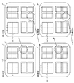
- the coding control unit 1 generates, for example, a block division state as illustrated in FIG. 6 for the coding block of the maximum size, and specifies the coding block B n .
- Shaded portion in FIG. 6 (a) shows the distribution of the partitions after splitting
- FIG. 6 (b) is a quadtree graph the situation where the coding mode m (B n) is assigned to the partition after the hierarchical division It shows by.
- the nodes surrounded by squares indicate nodes (coding blocks B n ) to which the coding mode m (B n ) is assigned.
- the encoding control unit 1 selects the optimal coding mode m (B n) for the partition P i n in each of the coding blocks B n, the encoding mode m (B n) is if intra-coding mode (step ST3), and outputs the partition P i n coded blocks B n which are divided by the block division unit 2 to the intra prediction unit 4.
- the long coding mode m (B n) is an inter coding mode (step ST3), the output partition P i n coded blocks B n which are divided by the block division unit 2 to the motion compensation prediction unit 5 Do.
- the intra prediction unit 4 uses the encoded image signal in the frame to generate the intra prediction parameter output from the coding control unit 1. based on, by carrying out the intra-frame prediction processing on partitioned P i n in the coded blocks B n, generates an intra prediction image P i n (step ST4).
- the intra prediction unit 4 after generating an intra prediction image P i n in the above, from among one or more filters prepared in advance, in the video decoding apparatus identical to the intra prediction image P i n predicted image select a filter according to the state of the various parameters are known at the time of generating and using the filter, carrying out the filtering processing for the intra prediction image P i n.
- Intra prediction unit 4 when carrying out filter processing of the intra prediction image P i n, but outputs the intra prediction image P i n after filtering the subtraction unit 6 and the addition section 9, even in the video decoding apparatus of FIG. 2 to be able to generate the same intra prediction image P i n, and outputs the intra prediction parameters in variable length coding unit 13.
- the outline of the processing content of the intra prediction unit 4 is as described above, but the detailed processing content will be described later.
- the motion compensation prediction unit 5 When receiving the partition P i n of the coding block B n from the changeover switch 3, the motion compensation prediction unit 5 uses the reference image of one or more frames stored in the motion compensation prediction frame memory 12 to execute the coding control unit based on the inter prediction parameter output from the 1, it generates an inter prediction image P i n by performing motion compensation prediction processing on partition P i n in the coded blocks B n (step ST5).
- generates an estimated image by implementing a motion compensation prediction process is a well-known technique, detailed description is abbreviate
- Subtraction unit 6 the intra prediction unit 4 or the motion compensation prediction unit 5 is predicted picture (intra prediction image P i n, inter prediction image P i n) when generating a coded block B n which are divided by the block division unit 2 from the partition P i n, the intra prediction unit 4 or the motion compensation prediction unit predicted image generated by 5 (the intra prediction image P i n, inter prediction image P i n) to generate a difference image by subtracting the, the a prediction error signal e i n representing a difference image is output to the transform and quantization unit 7 (step ST6).
- Transform and quantization unit 7 receives the prediction error signal e i n that indicates a difference image from the subtraction unit 6, conversion block size contained in the prediction error encoding parameters output from the coding controller 1 Performing transformation processing of the difference image (for example, DCT (Discrete Cosine Transformation) or orthogonal transformation processing such as KL transformation in which a basic design is previously performed on a specific learning sequence) and prediction error encoding
- transformation processing of the difference image for example, DCT (Discrete Cosine Transformation) or orthogonal transformation processing such as KL transformation in which a basic design is previously performed on a specific learning sequence
- KL transformation a basic design is previously performed on a specific learning sequence
- the inverse quantization / inverse transform unit 8 uses the quantization parameter included in the prediction error coding parameter output from the coding control unit 1.
- Compressed data of the difference image and inverse transform processing of compressed data of inverse quantization (eg, inverse DCT (inverse discrete cosine transform) in units of transform block size included in the prediction error coding parameter ) and, by performing an inverse transformation processing) inverse KL transform, etc., inverse transform compressed data after processing the locally decoded prediction error signal e i n hat (the relationship of the electronic application, with the alphabetic character " ⁇ " Is output as a hat) to the adder 9 (step ST8).
- inverse transform processing of compressed data of inverse quantization eg, inverse DCT (inverse discrete cosine transform) in units of transform block size included in the prediction error coding parameter
- inverse KL transform etc.
- Adding unit 9 from the inverse quantization and inverse transform unit 8 receives the locally decoded prediction error signal e i n hat, and the locally decoded prediction error signal e i n hat, by the intra prediction unit 4 or the motion compensation prediction unit 5 the generated predicted image (intra-prediction image P i n, inter prediction image P i n) by adding the prediction signal indicating, in local decoded partition image P i n hat or locally decoded coded block image as the collection A certain local decoded image is generated (step ST9).
- the addition unit 9 stores the locally decoded image signal indicating the locally decoded image in the intra prediction memory 10 and outputs the locally decoded image signal to the loop filter unit 11.
- steps ST3 to ST9 is repeatedly performed until the processing for all the coding blocks B n divided hierarchically is completed, and when the processing for all the coding blocks B n is completed, the processing proceeds to step ST12 (Steps ST10 and ST11).
- the variable-length coding unit 13 includes the compressed data output from the transform / quantization unit 7, the coding mode (including information indicating the division state of the coding block) and the prediction error output from the coding control unit 1. Entropy coding is performed on the coding parameter and the intra prediction parameter output from the intra prediction unit 4 or the inter prediction parameter output from the motion compensation prediction unit 5. The variable-length coding unit 13 multiplexes compressed data, which is the coding result of entropy coding, coding data, coding mode, prediction error coding parameters, and intra prediction parameters / inter prediction parameters to generate a bit stream. (Step ST12).
- the loop filter unit 11 compensates for the encoding distortion included in the locally decoded image signal, and the locally decoded image indicated by the locally decoded image signal after the encoding distortion compensation Are stored in the motion compensation prediction frame memory 12 as a reference image (step ST13).
- the filtering process by the loop filter unit 11 may be performed in units of largest encoded blocks of the locally decoded image signal output from the adder 9 or in individual encoded blocks, or in units of grouping of a plurality of largest encoded blocks. Alternatively, one picture may be grouped together after the local decoded image signal for one picture is output.
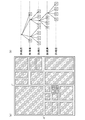
- FIG. 7 is an explanatory view showing an example of a selectable intra prediction parameters in each partition P i n in the encoding block B n (intra prediction mode).
- intra prediction mode and the prediction direction vector indicated by the intra prediction mode are represented, and the relative angle between the prediction direction vectors decreases as the number of selectable intra prediction modes increases. doing.
- Intra prediction unit 4 and the intra prediction parameters for the partition P i n, based on the selected parameters of the filters used to generate the intra prediction image P i n, performing the intra prediction process for partition P i n.
- intra prediction parameters intra prediction mode
- intra prediction mode for the luminance signal partitions P i n
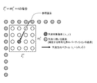
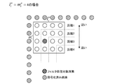
- the pixels used for the partition P i n in the prediction pixels (2 ⁇ m i n) pixels already encoded on the partition (2 ⁇ l i n +1) pieces and left partition adjacent The pixels used for prediction may be more or less than the pixels shown in FIG. Further, although in FIG. 8 pixels for one row or column adjacent to each other are used for prediction, pixels for two rows or two columns or more may be used for prediction.
- the position of the reference pixel used for prediction is the intersection of A and the adjacent pixel shown below.
- the integer pixel When the reference pixel is at an integer pixel position, the integer pixel is set as the prediction value of the prediction target pixel. On the other hand, when the reference pixel is not at the integer pixel position, the interpolation pixel generated from the integer pixel adjacent to the reference pixel is set as the prediction value. In the example of FIG. 8, since the reference pixel is not at the integer pixel position, the prediction value is calculated by interpolating from two pixels adjacent to the reference pixel. However, the predicted value is not limited to the two adjacent pixels, and an interpolated pixel may be generated from two or more adjacent pixels to be used as the predicted value.
- the intra prediction parameters used for generating the intra prediction image P i n outputs to the variable length coding unit 13 for multiplexing the bitstream.
- the filter to be used is selected by the method mentioned later out of the at least 1 or more filter prepared beforehand, and a filter process is performed with respect to each pixel of an intermediate
- N is an arbitrary number of reference pixels.
- s (p n ) represents the luminance value of each reference pixel, and s hat (p 0 ) represents the luminance value after filtering in the pixel p 0 to be filtered.
- the filter coefficients may be configured that there is no offset coefficient a N.
- the partition P i n the luminance values of the reference pixels within s (p n) may be a luminance value of each pixel of the intermediate prediction image, and the luminance value after filtering only filtered pixel position You may do it.
- the partition P i n the outside to become luminance value s of the reference pixels (p n), if coded region, the luminance value after encoding (luminance value to be decoded), yet been encoded If the region is not present, a signal to be substituted according to a predetermined procedure out of the brightness value s (p n ) of each reference pixel in the partition P i n defined above and the brightness value after encoding of the encoded region Select a value (eg, select the signal value at the closest position among the candidate pixels).
- the filtering process When performing the filtering process, as the size of the partition P i n (l i n ⁇ m i n) is large, non-straight edges such as is likely to exist in the input image, the predicted direction of the intermediate prediction image It is preferable to smooth the intermediate predicted image because a shift easily occurs. Furthermore, the larger the quantized value of the prediction error, quantization distortion generated in the decoded image is increased, because the prediction accuracy of the intermediate predicted image generated from encoded pixels adjacent to the partition P i n is lower it is preferable to prepare a predicted image such smoothed to roughly represent the partition P i n.
- intra prediction when generating an intermediate prediction image is one of two different methods: average value prediction in which all prediction values in a prediction block become the same value and prediction using prediction direction vector v p
- the reference pixel at the integer pixel position is used as it is as the prediction value and the reference pixel of at least two pixels or more.
- Interpolation is performed to generate a pixel that is not at an integer pixel position, and the arrangement in the prediction block of the pixel having the pixel value as a prediction value differs depending on the direction of the prediction direction vector v p . Therefore, it is better to change the filter strength, the number of reference pixels of the filter, the reference pixel arrangement, etc. depending on the index value of the intra prediction mode because the property of the predicted image differs depending on the intra prediction mode and the optimum filter processing also differs. .
- filters are selected in consideration of the following four parameters (1) to (4).
- Quantization parameter included in prediction error coding parameter (3) A group of coded pixels ("Pixel used for prediction" shown in FIG. 8) group to be used when generating an intermediate prediction image (4) Index value of intra prediction mode when generating intermediate prediction image
- the filter processing target pixel and the left and above the partition P i n As the distance to a certain encoded pixel group increases, a filter with a higher level of smoothing and a filter with a larger number of reference pixels are used. As an example of a distance between the coded pixel group in the filtering target pixel and left and upper partition P i n can be mentioned FIG. Also, the filter strength, the number of reference pixels of the filter, the reference pixel arrangement, and the like are switched depending on the index value of the intra prediction mode.
- adaptive selection of filters according to the above-described parameters is realized by correlating appropriate filters from among the previously prepared filters for each combination of the above-mentioned parameters.
- the definition of “distance to the encoded pixel group” of the parameter (3) is adapted according to the “intra prediction mode” of the parameter (4) It may be changed in That is, the definition of the distance to the encoded pixel group may not be fixed as shown in FIG. 11, but may be a distance depending on the prediction direction such as the distance from the “reference pixel” shown in FIG. By doing this, it is possible to realize adaptive filtering that takes into consideration the relationship between a plurality of parameters such as parameters (3) and (4).
- combinations in which the filtering process is not performed may be prepared in association with “no filtering process”.
- the weakest filter may be defined as "no filtering”.
- the four parameters (1) to (4) are known parameters on the moving picture decoding device side, additional information to be encoded which is necessary for performing the above-mentioned filter processing does not occur at all.
- switching of the filters is performed by preparing and adaptively selecting the necessary number of filters in advance, but the filters may be calculated so that the filters are calculated according to the value of the filter selection parameter.
- the filter switching may be realized by defining it as a function of the filter selection parameter.
- the filter is selected in consideration of the four parameters (1) to (4), but at least at least one of the four parameters (1) to (4)
- the filter may be configured to select one or more parameters in consideration.
- adaptive selection of filters is carried out by correlating appropriate filters from among a group of filters prepared in advance for each combination of parameters. The structural example of a filter process is shown.
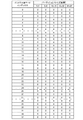
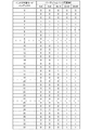
- FIG 13 is an explanatory diagram showing an example of a table indicating the filter used in the intra prediction mode of each partition size P i n.
- P i n size 4 ⁇ 4 pixels to be taken 8 ⁇ 8 pixels, 16 ⁇ 16 pixels, 32 ⁇ 32 pixels, 64 ⁇ and 64 pixels, the index values and corresponding Figure intra prediction direction of the intra prediction modes As per 7.
- the filter index 0 represents that no filter processing is performed.
- every combination of parameters (1) and (4) taking into consideration the characteristics of the image in intra prediction as in the table shown in FIG.
- the filter can be simplified.
- filtering for partition P i n can be simplified to the following filtering in each area shown in FIG. 14.
- Filter index 2 filter
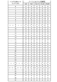
- the table of FIG. 13 is used in the above-mentioned example, other tables may be used.
- the table of FIG. 19 instead of the table of FIG.
- size 4 ⁇ 4 pixels of the partition P i n because you have 8 ⁇ 8 pixels, performs a filtering process only on the average prediction of 16 ⁇ 16 pixels, than the case of using a table of FIG. 13
- filter processing with extremely low processing load can be realized.
- a filter of filter index 2 may be used.
- an amount equivalent to perform the processing corresponding size of the partition P i n although the effect of improving the coding performance by the filter is reduced, (in the case of software the number of lines of code) circuit scale for implementing be suppressed it can.
- the present filter processing is a filter in which only the parameter (4) is taken into consideration among the four parameters (1) to (4).
- the filtering process to be executed for each size of the partition P i n is directly implemented even if it is not implemented by selecting the filter of the corresponding filter index by table reference, or filtering process performed for each pixel position of each size of the partition P i n are mounted directly or in a form directly filter is implemented as such.
- the form of implementation does not matter as long as the predicted images obtained as a result of the filtering process are equivalent even if the table is not referred to.
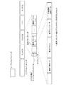
- the filter selection table may be switched in a predetermined unit by being configured to encode 100 as header information. For example, as shown in FIG. 15, by adding the filter selection table index 100 to the sequence level header, it is possible to perform filtering according to the characteristics of the sequence than when only a single table is used.
- the MPEG-4 AVC / H Similar to the smoothing process performed on the reference image at the time of 8 ⁇ 8 pixel block intra prediction of the 264, the reference pixels in generating the intermediate prediction image of partition P i n in the intra prediction unit 4, the partition even when the coded pixels adjacent to the P i n configured to the pixels smoothed, it is possible to perform the filtering for the same intermediate predicted image and the above example.
- the smoothing process for the reference pixel when generating the intermediate predicted image and the effect of the filter process for the intermediate predicted image have overlapping portions, so either process was performed even if both processes were used simultaneously. Only a slight improvement in performance may be obtained compared to the case.
- the configuration is such that filter processing is not performed on the intermediate prediction image on the partition P i n that is performing smoothing processing on reference pixels when generating the intermediate prediction image.
- the filtering process for the intermediate prediction image is performed by filtering only the average prediction as shown in the table of FIG. 19, and the smoothing process for reference pixels when generating the intermediate prediction image is specific as shown in FIG. It is conceivable to carry out with reference to a table which performs smoothing processing only for directionality prediction. However, in FIG. 20, '1' indicates that smoothing processing is performed, and '0' indicates that smoothing processing is not performed.
- Intra prediction parameters used to generate the intra prediction image P i n outputs to the variable length coding unit 13 for multiplexing the bitstream. Even for the color difference signals in the partition P i n, in the same procedure as the luminance signal, performing an intra prediction process based on the intra prediction parameters (intra prediction mode), an intra prediction parameter used to generate the intra-prediction image Is output to the variable-length coding unit 13.
- the filter processing described above may be configured to be performed in the same manner as the luminance signal, or may be configured not to be performed.
- variable length decoding unit 51 receives a bit stream output from the image coding apparatus shown in FIG. 1, the variable length decoding unit 51 performs variable length decoding processing on the bit stream to generate a sequence unit or picture composed of one or more frames
- the frame size information is decoded in units (step ST21 in FIG. 4).
- the variable-length decoding unit 51 performs processing similar to that performed by the coding control unit 1 of FIG. 1 when the intra prediction processing (intra-frame prediction processing) or motion compensation prediction processing (inter-frame prediction processing) is performed
- the maximum size of the coding block is determined, and the number of layers in the upper limit when the coding block of the maximum size is hierarchically divided is determined (step ST22).
- the maximum size of the coding block is determined according to the resolution of the input image, the maximum size of the coding block is determined based on the previously decoded frame size information. .
- the information decoded from the bit stream is referred to.
- the coding mode m (B 0 ) of the coding block B 0 of the largest size multiplexed in the bit stream includes information indicating the division state of the coding block B 0 of the largest size, it is variable.
- the long decoding unit 51 decodes the coding mode m (B 0 ) of the coding block B 0 of the maximum size multiplexed in the bit stream, and divides each coding block B n divided hierarchically. Are identified (step ST23).
- the variable length decoding unit 51 decodes the coding mode m (B n ) of the coding block B n , and belongs to the coding mode m (B n ).
- Variable-length decoding unit 51 has determined the partition P i n that belong to coded blocks B n, for each partition P i n, compressed data, coding mode, the prediction error coding parameters, intra prediction parameters / inter prediction The parameters are decoded (step ST24).
- the coding block B n assigned coding mode m (B n) if an intra coding mode, decodes the intra-prediction parameter for each partition P i n that belong to coded blocks. If the coding block B n assigned coding mode m (B n) is an inter coding mode, it decodes the inter prediction parameter for each partition P i n that belong to coded blocks.
- the partition serving as a prediction processing unit is further divided into one or more partitions serving as a conversion processing unit based on transform block size information included in the prediction error coding parameter, and compressed data (per partition serving as a transform processing unit) Decode transform coefficients after transform / quantization.
- Changeover switch 52 when the coding mode m of partitions P i n from the variable-length decoding unit 51 belonging to the coding block B n (B n) is an intra coding mode (step ST25), the variable length decoding unit The intra prediction parameter output from 51 is output to the intra prediction unit 53.
- the partition P i n coding modes m (B n) is an inter coding mode (step ST25), and outputs the inter prediction parameter outputted from the variable length decoding unit 51 to the motion compensation prediction unit 54.
- the intra prediction unit 53 When receiving the intra prediction parameter from the changeover switch 52, the intra prediction unit 53 encodes the decoded image signal in the frame based on the intra prediction parameter, as in the intra prediction unit 4 of FIG. performing the intra-frame prediction processing on partitioned P i n blocks B n in generating an intra prediction image P i n (step ST26). However, the intra prediction unit 53, after generating the intra prediction image P i n the above, in the same manner as the intra prediction unit 4 in FIG.
- the intra-prediction image select a filter according to the state of the various parameters are known at the time of generating the P i n, by using the filter, and out the filter processing for the intra prediction image P i n, intra prediction of the filtered an image P i n is the final intra-prediction image. That is, using the same parameter as the parameter used for filter selection in the intra prediction unit 4, a filter is selected by the same method as the filter selection method in the intra prediction unit 4, and filter processing is performed.
- filter index 0 corresponds to no filter processing
- four filters prepared in advance are associated with filter indexes 1 to 4 respectively.
- intra prediction unit 53 may define the same filter and filter index and the intra prediction unit 4, the filter selection by index of intra prediction mode is the size and the intra prediction parameters partitions P i n by referring to the table of FIG. 13 And configured to perform filtering.
- filter switching is realized by any of the forms shown in FIGS.
- the filter selection table index 100 is decoded as header information in step S.
- the table indicated by the decoded filter selection table index 100 is selected from the same table group as the moving image coding device prepared in advance, and the table is referred to. It may be configured to perform filter selection.
- the motion compensation prediction unit 54 uses the reference image of one or more frames stored in the motion compensation prediction frame memory 59 to encode blocks based on the inter prediction parameter. It generates an inter prediction image P i n by performing motion compensation prediction processing on partition P i n of B n (step ST27).
- the inverse quantization / inverse transform unit 55 relates to the coding block output from the variable length decoding unit 51 using the quantization parameter included in the prediction error coding parameter output from the variable length decoding unit 51.
- Inverse quantization processing of compression data of inverse quantization for example, inverse DCT (inverse discrete cosine transformation), inverse KL transformation, etc.
- the compressed data after the inverse conversion process is output as a decoded prediction error signal (a signal indicating a differential image before compression) to the adding unit 56 (step ST28).
- the adding unit 56 When the adding unit 56 receives the decoded prediction error signal from the inverse quantization / inverse converting unit 55, the adding unit 56 adds the decoded prediction error signal and the prediction signal indicating the prediction image generated by the intra prediction unit 53 or the motion compensation prediction unit 54.
- the decoded image is generated to store the decoded image signal indicating the decoded image in the intra prediction memory 57, and the decoded image signal is output to the loop filter unit 58 (step ST29).
- steps ST23 to ST29 are repeatedly performed until the process for all the coding blocks B n hierarchically divided is completed (step ST30).
- loop filter unit 58 compensates for the coding distortion included in the decoded image signal, and uses the decoded image indicated by the decoded image signal after the coding distortion compensation as a reference image.
- the motion compensation prediction frame memory 59 is stored (step ST31).
- the filtering process by the loop filter unit 58 may be performed in units of the largest encoded block of the decoded image signal output from the adder 56 or in individual encoded blocks, or a decoded image signal corresponding to a macroblock for one screen May be performed collectively for one screen after the output of.
- the intra prediction unit 4 of the video encoding apparatus performs intra-frame prediction processing by using the encoded image signal in the frame.
- a filter is selected in accordance with the state of various parameters related to the encoding of the filter processing target block from among one or more filters prepared in advance, and the filter is used to generate a predicted image. Since the filter processing is performed, it is possible to reduce locally generated prediction errors and to improve the image quality.
- a quantum intra prediction unit 4 is included (1) the size of the partition P i n (l i n ⁇ m i n), (2) the prediction error encoding parameters Parameter, (3) the distance between the encoded pixel group used when generating the intermediate prediction image and the pixel to be filtered, and (4) the index value of the intra prediction mode when generating the intermediate prediction image, at least Since the filter is selected in consideration of one or more parameters, the edge of the image to be encoded may be slightly non-linearly distorted or deviated in angle when performing directional prediction. This method has the effect of suppressing the prediction error at the boundary of the block, which is caused by loss of continuity with the adjacent encoded signal at the time of average value prediction or local prediction error that occurs in The prediction efficiency can be improved.
- the intra prediction unit 53 of the video decoding apparatus prepares in advance when generating an intra-prediction image by performing intra-frame prediction processing using a decoded image signal in a frame. Since the filter is selected according to the state of various parameters related to the decoding of the filter processing target block from among the one or more filters being processed, the filter processing is performed on the predicted image using the filter. There is an effect that the intra prediction image identical to the intra prediction image generated on the moving image coding device side can be generated on the moving image decoding device side by reducing the prediction error generated locally.
- a quantum intra prediction unit 53 is included (1) the size of the partition P i n (l i n ⁇ m i n), (2) the prediction error encoding parameters Parameter, (3) the distance between the encoded pixel group used when generating the intermediate prediction image and the pixel to be filtered, and (4) the index value of the intra prediction mode when generating the intermediate prediction image, at least Since the filter is selected in consideration of one or more parameters, the edge of the image to be encoded may be slightly non-linearly distorted or deviated in angle when performing directional prediction. Effect of suppressing the local prediction error that occurs in and the prediction error of the block boundary part that is caused by the loss of continuity with the adjacent encoded signal when the average value prediction is performed. There is an effect that the same moving picture decoding apparatus can generate the same intra predicted picture as the obtained intra prediction picture generated on the moving picture coding apparatus side.
- the intra prediction unit 4 when the intra prediction unit 4 generates the intra prediction image by performing the intra-frame prediction process using the encoded image signal in the frame, one or more prepared in advance.
- filters are selected according to the state of various parameters related to the encoding of the filter processing target block, and the filter processing is performed on the predicted image using the filter.
- Design a Wiener filter that minimizes the sum of squared errors between the block and the predicted image, and use the Wiener filter rather than using a filter that is selected from one or more of the provided filters. If the degree of reduction of the prediction error is high, the above-mentioned Wiener filter is used instead of the selected filter to Filtering of the may be performed. The contents of the process will be specifically described below.
- the intra prediction units 4 and 53 select a filter from among one or more filters prepared in advance, according to the state of various parameters related to the encoding of the filter processing target block. ing.
- the moving picture coding apparatus designs an optimum filter on a picture basis to perform filter processing, and encodes the filter coefficients and the like of the filter, and the moving picture decoding apparatus It is characterized in that filter processing using the filter is performed by decoding filter coefficients and the like.
- Intra prediction unit 4 of the moving picture coding apparatus generates an intra prediction image P i n by performing intra-frame prediction processing on partitioned P i n coded blocks B n .
- the intra prediction unit 4 selects one or more filters prepared in advance according to the state of various parameters relating to the encoding of the filtering target block in the same manner as in the first embodiment. selected, it performs a filtering process to the intra prediction image P i n using this filter.
- the intra prediction unit 4 determines the intra prediction parameters in all the coding blocks B n in the picture, and then, for each area (the area having the same filter index) in which the same filter is used in the picture, Design a Wiener filter that minimizes the sum of squared errors (the mean squared error in the target area) of the input image and the intra-predicted image.
- the Wiener filter has filter coefficients from the following equation (4) according to the autocorrelation matrix R s's ' of the intermediate predicted image signal s' and the cross correlation matrix R ss 'of the input image signal s and the intermediate predicted image signal s' We can get w.
- the magnitudes of the matrices R s's' and R ss' correspond to the number of filter taps to be determined.
- D1 represents the sum of squared errors in the filter design target area when the filter process is performed using the Wiener filter, and information (for example, a filter related to the Wiener filter)
- the sum of squared errors in the filter design target area is D2 when the filtering process is performed using R1 as the code amount when encoding the coefficient) and the filter that is selected by the same method as the first embodiment.
- the intra prediction unit 4 performs the filtering process using the Wiener filter instead of the filter selected in the same manner as in the first embodiment.
- filtering is performed using the filter selected in the same manner as in the first embodiment.
- evaluation is performed using the sum of squared errors D1 and D2.
- the present invention is not limited to this. Instead of the sum of squared errors D1 and D2, distortions of other predictions such as sum of absolute values of errors may be used. You may make it evaluate using the scale to represent.
- the filter coefficient of the Wiener filter and the filter update information indicating which index filter is replaced by the Wiener filter are required. Specifically, assuming that the number of filters selectable by filtering using filter selection parameters is L, and an index of 0 to L-1 is allocated to each filter, the designed Wiener filter for each index It is necessary to encode the value of “1” as filter update information when using “1”, and “0” when using a filter prepared in advance.
- the variable-length coding unit 13 performs variable-length coding on the filter update information output from the intra prediction unit 4 and multiplexes the coded data of the filter update information into a bit stream.
- a Wiener filter in which the mean square error of the input image and the predicted image in that area is minimized is shown, but it is not in units of pictures
- a Wiener filter may be designed to minimize the mean square error of the input image and the predicted image in the area, or Perform filter design only in a specific picture, or perform the above filter design only in the case where a specific condition is satisfied (for example, a scene change detection function is added and a scene change is detected). You may do so.
- the variable-length decoding unit 51 of the video decoding apparatus performs variable-length decoding of the filter update information from the encoded data multiplexed in the bit stream.
- the intra prediction unit 53 as in the first embodiment, generates an intra prediction image P i n by performing intra-frame prediction processing on partitioned P i n coded blocks B n.
- the intra prediction unit 53 Upon receiving the filter update information from the variable length decoding unit 51, the intra prediction unit 53 refers to the filter update information and confirms the presence or absence of the update by the filter of the corresponding index.
- the intra prediction unit 53 reads out the filter coefficients of the Wiener filter included in the filter update information, and the Wiener filter identify, using the Wiener filter performs a filtering of the intra prediction image P i n.
- the areas not replaced by Wiener filter select the filter in the same manner as in the first embodiment, by using the filter, carrying out the filtering of the intra prediction image P i n.
- a Wiener filter is designed to minimize the sum of squared errors between the block to be encoded and the predicted image, and one or more filters prepared in advance are used. If using the Wiener filter reduces the prediction error more than using a selected filter, use the Wiener filter instead of the selected filter to obtain a predicted image. Since the filter processing for the above is implemented, the effect of being able to reduce the prediction error generated locally more than the first embodiment is exhibited.
- the present invention allows free combination of each embodiment, or modification of any component of each embodiment, or omission of any component in each embodiment. .
- the present invention is suitable for a moving picture coding apparatus that needs to perform moving picture coding with high efficiency, and to a moving picture decoding apparatus that needs to decode moving pictures that are highly efficiently coded. Is suitable.
Abstract
Priority Applications (28)
| Application Number | Priority Date | Filing Date | Title |
|---|---|---|---|
| KR1020167007830A KR101643528B1 (ko) | 2011-01-12 | 2012-01-06 | 화상 부호화 장치, 화상 복호 장치, 화상 부호화 방법, 화상 복호 방법 및 기억 매체 |
| JP2012552668A JP5478740B2 (ja) | 2011-01-12 | 2012-01-06 | 動画像符号化装置、動画像復号装置、動画像符号化方法及び動画像復号方法 |
| BR112013016961-3A BR112013016961B1 (pt) | 2011-01-12 | 2012-01-06 | Dispositivos de codificação e de decodificação de imagem, e, métodos de codificação e de decodificação de imagem |
| KR1020167007837A KR101643121B1 (ko) | 2011-01-12 | 2012-01-06 | 화상 부호화 장치, 화상 복호 장치, 화상 부호화 방법, 화상 복호 방법 및 기억 매체 |
| KR1020137021198A KR101547041B1 (ko) | 2011-01-12 | 2012-01-06 | 화상 부호화 장치, 화상 복호 장치, 화상 부호화 방법 및 화상 복호 방법 |
| MX2013008119A MX2013008119A (es) | 2011-01-12 | 2012-01-06 | Dispositivo de codificacion de imagen, dispositivo de decodificacion de imagen, metodo de codificacion de imagen y metodo de decodificacion de imagen. |
| US13/979,357 US9299133B2 (en) | 2011-01-12 | 2012-01-06 | Image encoding device, image decoding device, image encoding method, and image decoding method for generating a prediction image |
| RU2013137436/08A RU2565038C2 (ru) | 2011-01-12 | 2012-01-06 | Устройство кодирования изображений, устройство декодирования изображений, способ кодирования изображений и способ декодирования изобраений |
| KR1020147012785A KR101609490B1 (ko) | 2011-01-12 | 2012-01-06 | 화상 부호화 장치, 화상 복호 장치, 화상 부호화 방법 및 화상 복호 방법 |
| SG2013051685A SG191845A1 (en) | 2011-01-12 | 2012-01-06 | Moving image encoding device, moving image decoding device, moving image encoding method, and moving image decoding method |
| KR1020167018949A KR101678351B1 (ko) | 2011-01-12 | 2012-01-06 | 기억 매체 |
| CA2823503A CA2823503C (fr) | 2011-01-12 | 2012-01-06 | Dispositif de codage d'image, dispositif de decodage d'image, procede decodage d'image et procede de decodage d'image |
| KR1020157002180A KR101604959B1 (ko) | 2011-01-12 | 2012-01-06 | 화상 부호화 장치, 화상 복호 장치, 화상 부호화 방법 및 화상 복호 방법 |
| EP12734737.5A EP2665274A4 (fr) | 2011-01-12 | 2012-01-06 | Dispositif de codage d'image dynamique, dispositif de décodage d'image dynamique, procédé de codage d'image dynamique et procédé de décodage d'image dynamique |
| CN201280005061.6A CN103299637B (zh) | 2011-01-12 | 2012-01-06 | 图像编码装置、图像译码装置、图像编码方法以及图像译码方法 |
| TW107106370A TWI673687B (zh) | 2011-01-12 | 2012-01-11 | 畫像編碼裝置、畫像解碼裝置、畫像編碼方法、畫像解碼方法及記憶媒體 |
| TW109135515A TWI792075B (zh) | 2011-01-12 | 2012-01-11 | 畫像編碼裝置、畫像解碼裝置、畫像編碼方法、畫像解碼方法及記憶媒體 |
| TW101101051A TWI529664B (zh) | 2011-01-12 | 2012-01-11 | 畫像編碼裝置及畫像解碼裝置 |
| TW108131065A TWI711296B (zh) | 2011-01-12 | 2012-01-11 | 畫像編碼裝置、畫像解碼裝置、畫像編碼方法、畫像解碼方法及記憶媒體 |
| TW105105865A TWI579803B (zh) | 2011-01-12 | 2012-01-11 | 畫像編碼裝置、畫像解碼裝置、畫像編碼方法、畫像解碼方法及記憶媒體 |
| TW106106816A TWI620150B (zh) | 2011-01-12 | 2012-01-11 | 畫像編碼裝置、畫像解碼裝置、畫像編碼方法、畫像解碼方法及記憶媒體 |
| HK13113477.0A HK1186323A1 (zh) | 2011-01-12 | 2013-12-04 | 圖像編碼裝置、圖像譯碼裝置、圖像編碼方法以及圖像譯碼方法 |
| US14/977,045 US9736478B2 (en) | 2011-01-12 | 2015-12-21 | Image encoding device, image decoding device, image encoding method, and image decoding method for generating a prediction image |
| US14/977,218 US9628797B2 (en) | 2011-01-12 | 2015-12-21 | Image encoding device, image decoding device, image encoding method, and image decoding method for generating a prediction image |
| US14/977,236 US9414073B2 (en) | 2011-01-12 | 2015-12-21 | Image encoding device, image decoding device, image encoding method, and image decoding method for generating a prediction image |
| US14/977,170 US9609326B2 (en) | 2011-01-12 | 2015-12-21 | Image encoding device, image decoding device, image encoding method, and image decoding method for generating a prediction image |
| US15/192,698 US10205944B2 (en) | 2011-01-12 | 2016-06-24 | Image encoding device, image decoding device, image encoding method, and image decoding method for generating a prediction image |
| US16/228,053 US10931946B2 (en) | 2011-01-12 | 2018-12-20 | Image encoding device, image decoding device, image encoding method, and image decoding method for generating a prediction image |
Applications Claiming Priority (2)
| Application Number | Priority Date | Filing Date | Title |
|---|---|---|---|
| JP2011-004038 | 2011-01-12 | ||
| JP2011004038 | 2011-01-12 |
Related Child Applications (5)
| Application Number | Title | Priority Date | Filing Date |
|---|---|---|---|
| US13/979,357 A-371-Of-International US9299133B2 (en) | 2011-01-12 | 2012-01-06 | Image encoding device, image decoding device, image encoding method, and image decoding method for generating a prediction image |
| US14/977,170 Division US9609326B2 (en) | 2011-01-12 | 2015-12-21 | Image encoding device, image decoding device, image encoding method, and image decoding method for generating a prediction image |
| US14/977,236 Division US9414073B2 (en) | 2011-01-12 | 2015-12-21 | Image encoding device, image decoding device, image encoding method, and image decoding method for generating a prediction image |
| US14/977,045 Division US9736478B2 (en) | 2011-01-12 | 2015-12-21 | Image encoding device, image decoding device, image encoding method, and image decoding method for generating a prediction image |
| US14/977,218 Division US9628797B2 (en) | 2011-01-12 | 2015-12-21 | Image encoding device, image decoding device, image encoding method, and image decoding method for generating a prediction image |
Publications (1)
| Publication Number | Publication Date |
|---|---|
| WO2012096150A1 true WO2012096150A1 (fr) | 2012-07-19 |
Family
ID=46507059
Family Applications (1)
| Application Number | Title | Priority Date | Filing Date |
|---|---|---|---|
| PCT/JP2012/000061 WO2012096150A1 (fr) | 2011-01-12 | 2012-01-06 | Dispositif de codage d'image dynamique, dispositif de décodage d'image dynamique, procédé de codage d'image dynamique et procédé de décodage d'image dynamique |
Country Status (13)
| Country | Link |
|---|---|
| US (7) | US9299133B2 (fr) |
| EP (1) | EP2665274A4 (fr) |
| JP (8) | JP5478740B2 (fr) |
| KR (6) | KR101643121B1 (fr) |
| CN (5) | CN105872565B (fr) |
| BR (1) | BR112013016961B1 (fr) |
| CA (5) | CA2979455C (fr) |
| HK (5) | HK1186323A1 (fr) |
| MX (1) | MX2013008119A (fr) |
| RU (5) | RU2565038C2 (fr) |
| SG (4) | SG10201810141WA (fr) |
| TW (6) | TWI529664B (fr) |
| WO (1) | WO2012096150A1 (fr) |
Cited By (19)
| Publication number | Priority date | Publication date | Assignee | Title |
|---|---|---|---|---|
| JP2013534384A (ja) * | 2010-07-31 | 2013-09-02 | オ,ス−ミ | イントラ予測復号化装置 |
| JP2013535919A (ja) * | 2010-07-31 | 2013-09-12 | オ,ス−ミ | 予測ブロック生成装置 |
| JP2013543315A (ja) * | 2010-10-01 | 2013-11-28 | クゥアルコム・インコーポレイテッド | ビデオコード化のためのイントラ平滑化フィルタ |
| WO2014049981A1 (fr) * | 2012-09-28 | 2014-04-03 | 三菱電機株式会社 | Dispositif de codage vidéo, dispositif de décodage vidéo, procédé de codage vidéo et procédé de décodage vidéo |
| JP2014064249A (ja) * | 2012-09-24 | 2014-04-10 | Ntt Docomo Inc | 動画像予測符号化装置、動画像予測符号化方法、動画像予測復号装置及び動画像予測復号方法 |
| JP2014143671A (ja) * | 2012-12-28 | 2014-08-07 | Canon Inc | 画像符号化装置、画像符号化方法及びプログラム、画像復号装置、画像復号方法及びプログラム |
| JP2014519768A (ja) * | 2011-06-20 | 2014-08-14 | メディア テック シンガポール ピーティーイー.リミテッド | 方向性イントラ予測の方法及び装置 |
| US9154781B2 (en) | 2011-06-20 | 2015-10-06 | Electronics And Telecommunications Research Institute | Image encoding/decoding method and apparatus for same |
| JP2016012928A (ja) * | 2015-08-21 | 2016-01-21 | 株式会社Nttドコモ | 動画像予測符号化装置、動画像予測符号化方法、動画像予測復号装置及び動画像予測復号方法 |
| JP2016136786A (ja) * | 2016-04-28 | 2016-07-28 | 株式会社Nttドコモ | 動画像予測符号化装置、動画像予測符号化方法、動画像予測復号装置及び動画像予測復号方法 |
| JP2017112629A (ja) * | 2017-02-03 | 2017-06-22 | 株式会社Nttドコモ | 動画像予測復号装置及び動画像予測復号方法 |
| US9723316B2 (en) | 2011-06-24 | 2017-08-01 | Mitsubishi Electric Corporation | Image encoding device, image decoding device, image encoding method, image decoding method, and image prediction device |
| JP2018050320A (ja) * | 2017-11-07 | 2018-03-29 | 株式会社Nttドコモ | 動画像予測復号方法 |
| JP2019013040A (ja) * | 2018-09-20 | 2019-01-24 | 株式会社Nttドコモ | 動画像予測復号方法 |
| CN109937571A (zh) * | 2016-09-05 | 2019-06-25 | Lg电子株式会社 | 图像编码/解码方法及其装置 |
| WO2019189904A1 (fr) * | 2018-03-30 | 2019-10-03 | 日本放送協会 | Dispositif de prédiction intra, dispositif de codage d'image, dispositif de décodage d'image et programme |
| RU2715519C1 (ru) * | 2012-07-02 | 2020-02-28 | Нтт Докомо, Инк. | Устройство кодирования видео с предсказанием, способ кодирования видео с предсказанием, программа кодирования видео с предсказанием, устройство декодирования видео с предсказанием, способ декодирования видео с предсказанием и программа декодирования видео с предсказанием |
| JP2020509714A (ja) * | 2017-04-04 | 2020-03-26 | ホアウェイ・テクノロジーズ・カンパニー・リミテッド | ピクチャブロックのイントラ予測に使用される参照サンプルの処理 |
| US11228755B2 (en) | 2016-03-17 | 2022-01-18 | Industry Academy Cooperation Foundation Of Sejong University | Method and apparatus for processing intra-prediction-based video signal |
Families Citing this family (28)
| Publication number | Priority date | Publication date | Assignee | Title |
|---|---|---|---|---|
| CA2979455C (fr) * | 2011-01-12 | 2018-09-04 | Mitsubishi Electric Corporation | Dispositif de codage d'image, dispositif de decodage d'image, procede decodage d'image et procede de decodage d'image |
| CN102884794B (zh) * | 2011-03-07 | 2016-08-10 | 松下知识产权经营株式会社 | 运动补偿装置、运动图像编码装置、运动图像解码装置、运动补偿方法、以及集成电路 |
| US9621902B2 (en) * | 2013-02-28 | 2017-04-11 | Google Inc. | Multi-stream optimization |
| WO2015115644A1 (fr) * | 2014-02-03 | 2015-08-06 | 三菱電機株式会社 | Dispositif de codage d'image, dispositif de décodage d'image, dispositif de conversion de flux codé, procédé de codage d'image et procédé de décodage d'image |
| US9210662B1 (en) * | 2014-05-29 | 2015-12-08 | Apple Inc. | Adaptive battery life extension |
| FR3040578A1 (fr) * | 2015-08-31 | 2017-03-03 | Orange | Procede de codage et de decodage d'images, dispositif de codage et de decodage d'images et programmes d'ordinateur correspondants |
| CN108293111B (zh) * | 2015-10-16 | 2022-07-08 | Lg电子株式会社 | 改善图像编码系统中的预测的滤波方法、装置和存储介质 |
| RU2018132742A (ru) * | 2016-02-16 | 2020-03-17 | Самсунг Электроникс Ко., Лтд. | Способ внутреннего предсказания для уменьшения ошибок внутреннего предсказания и устройство для этого |
| US11095898B2 (en) | 2016-03-28 | 2021-08-17 | Lg Electronics Inc. | Inter-prediction mode based image processing method, and apparatus therefor |
| CN110024388B (zh) | 2016-10-10 | 2023-09-22 | 三星电子株式会社 | 图像解码方法 |
| CN116320494A (zh) | 2016-11-28 | 2023-06-23 | 韩国电子通信研究院 | 用于滤波的方法和装置 |
| KR102387909B1 (ko) * | 2016-11-29 | 2022-04-18 | 한국전자통신연구원 | 영상 부호화/복호화 방법, 장치 및 비트스트림을 저장한 기록 매체 |
| US10992939B2 (en) | 2017-10-23 | 2021-04-27 | Google Llc | Directional intra-prediction coding |
| US10225578B2 (en) | 2017-05-09 | 2019-03-05 | Google Llc | Intra-prediction edge filtering |
| MX2019014415A (es) | 2017-06-16 | 2020-02-05 | Eisai R&D Man Co Ltd | Compuesto monomerico de acido nucleico modificado y analogo de acido oligonucleico. |
| WO2019137730A1 (fr) * | 2018-01-11 | 2019-07-18 | Telefonaktiebolaget Lm Ericsson (Publ) | Filtrage de limite multiple |
| US11451791B2 (en) | 2018-01-25 | 2022-09-20 | Wilus Institute Of Standards And Technology Inc. | Video signal processing method and device |
| WO2019157717A1 (fr) * | 2018-02-14 | 2019-08-22 | 北京大学 | Procédé et dispositif de compensation de mouvement, et système informatique |
| CN110290384A (zh) * | 2018-03-19 | 2019-09-27 | 华为技术有限公司 | 图像滤波方法、装置及视频编解码器 |
| CN117640950A (zh) * | 2018-05-23 | 2024-03-01 | 松下电器(美国)知识产权公司 | 解码装置和编码装置 |
| CN113347423B (zh) | 2018-06-25 | 2023-04-21 | Oppo广东移动通信有限公司 | 帧内预测方法和装置 |
| US10701376B2 (en) * | 2018-07-05 | 2020-06-30 | Awecom, Inc. | Resilient image compression and decompression |
| RU2726160C1 (ru) * | 2019-04-29 | 2020-07-09 | Самсунг Электроникс Ко., Лтд. | Повторный синтез изображения, использующий прямое деформирование изображения, дискриминаторы пропусков и основанное на координатах реконструирование |
| KR20230156456A (ko) * | 2019-01-10 | 2023-11-14 | 후아웨이 테크놀러지 컴퍼니 리미티드 | 인트라 서브파티션 코딩 툴로 인한 서브파티션 경계를 위한 디블로킹 필터 |
| US10778972B1 (en) | 2019-02-27 | 2020-09-15 | Google Llc | Adaptive filter intra prediction modes in image/video compression |
| JP7383119B2 (ja) | 2019-07-26 | 2023-11-17 | 北京字節跳動網絡技術有限公司 | 映像コーディングモードのブロックサイズ依存使用 |
| WO2021018084A1 (fr) * | 2019-07-26 | 2021-02-04 | Beijing Bytedance Network Technology Co., Ltd. | Interdépendance de la taille de transformée et de la taille d'une unité d'arbre de codage dans un codage vidéo |
| CN116385414B (zh) * | 2023-04-10 | 2023-11-07 | 哈尔滨耐是智能科技有限公司 | 零部件多尺度缺陷特征提取方法、计算设备及存储介质 |
Citations (4)
| Publication number | Priority date | Publication date | Assignee | Title |
|---|---|---|---|---|
| WO2009120040A2 (fr) * | 2008-03-27 | 2009-10-01 | Lg Electronics Inc. | Procédé et appareil de codage ou décodage d'un signal vidéo |
| WO2010143427A1 (fr) * | 2009-06-10 | 2010-12-16 | パナソニック株式会社 | Procédé d'encodage d'image, procédé de décodage d'image et dispositifs correspondants |
| WO2011132400A1 (fr) * | 2010-04-22 | 2011-10-27 | パナソニック株式会社 | Procédé de codage d'image, et procédé de décodage d'image |
| WO2012008125A1 (fr) * | 2010-07-15 | 2012-01-19 | 三菱電機株式会社 | Dispositif de codage vidéo, dispositif de décodage vidéo, procédé de codage vidéo et procédé de décodage vidéo |
Family Cites Families (102)
| Publication number | Priority date | Publication date | Assignee | Title |
|---|---|---|---|---|
| JPH08237669A (ja) * | 1995-02-28 | 1996-09-13 | Sony Corp | 画像信号処理装置、画像信号処理方法および画像信号復号化装置 |
| JP3392307B2 (ja) * | 1995-11-02 | 2003-03-31 | 松下電器産業株式会社 | 画像信号平滑化装置および画像信号平滑化方法 |
| US6041145A (en) | 1995-11-02 | 2000-03-21 | Matsushita Electric Industrial Co., Ltd. | Device and method for smoothing picture signal, device and method for encoding picture and device and method for decoding picture |
| JPH10224790A (ja) * | 1997-02-07 | 1998-08-21 | Matsushita Electric Ind Co Ltd | 圧縮伸張された画像中のブロック状ノイズを除去するフィルタおよびフィルタ方法 |
| US6188799B1 (en) | 1997-02-07 | 2001-02-13 | Matsushita Electric Industrial Co., Ltd. | Method and apparatus for removing noise in still and moving pictures |
| JP3095140B2 (ja) * | 1997-03-10 | 2000-10-03 | 三星電子株式会社 | ブロック化効果の低減のための一次元信号適応フィルター及びフィルタリング方法 |
| US6181382B1 (en) * | 1998-04-03 | 2001-01-30 | Miranda Technologies Inc. | HDTV up converter |
| US6122321A (en) * | 1998-05-12 | 2000-09-19 | Hitachi America, Ltd. | Methods and apparatus for reducing the complexity of inverse quantization operations |
| US6584154B1 (en) | 1998-11-26 | 2003-06-24 | Oki Electric Industry Co., Ltd. | Moving-picture coding and decoding method and apparatus with reduced computational cost |
| CN101448162B (zh) * | 2001-12-17 | 2013-01-02 | 微软公司 | 处理视频图像的方法 |
| US7386048B2 (en) * | 2002-05-28 | 2008-06-10 | Sharp Laboratories Of America, Inc. | Methods and systems for image intra-prediction mode organization |
| US7289672B2 (en) * | 2002-05-28 | 2007-10-30 | Sharp Laboratories Of America, Inc. | Methods and systems for image intra-prediction mode estimation |
| US20060256867A1 (en) * | 2002-09-06 | 2006-11-16 | Turaga Deepak S | Content-adaptive multiple description motion compensation for improved efficiency and error resilience |
| AU2003279015A1 (en) * | 2002-09-27 | 2004-04-19 | Videosoft, Inc. | Real-time video coding/decoding |
| CN1232126C (zh) * | 2002-09-30 | 2005-12-14 | 三星电子株式会社 | 图像编码方法和装置以及图像解码方法和装置 |
| US7010044B2 (en) * | 2003-07-18 | 2006-03-07 | Lsi Logic Corporation | Intra 4×4 modes 3, 7 and 8 availability determination intra estimation and compensation |
| US7426308B2 (en) * | 2003-07-18 | 2008-09-16 | Microsoft Corporation | Intraframe and interframe interlace coding and decoding |
| KR101050828B1 (ko) * | 2003-08-26 | 2011-07-21 | 톰슨 라이센싱 | 하이브리드 인트라-인터 코딩된 블록을 디코딩하기 위한 방법 및 장치 |
| US7724827B2 (en) * | 2003-09-07 | 2010-05-25 | Microsoft Corporation | Multi-layer run level encoding and decoding |
| CN100534192C (zh) * | 2003-10-28 | 2009-08-26 | 松下电器产业株式会社 | 帧内预测编码方法 |
| EP2224724A3 (fr) | 2003-12-27 | 2012-04-11 | Samsung Electronics Co., Ltd. | Procédé de codage et de décodage utilisant un échantillonnage du résidue |
| CN100536573C (zh) * | 2004-01-16 | 2009-09-02 | 北京工业大学 | 基于方向的dc预测方法及用于视频编码的帧内预测方法 |
| JP2006032999A (ja) | 2004-07-12 | 2006-02-02 | Sharp Corp | 画像復号装置及び画像復号方法 |
| US8085846B2 (en) * | 2004-08-24 | 2011-12-27 | Thomson Licensing | Method and apparatus for decoding hybrid intra-inter coded blocks |
| JP4495580B2 (ja) * | 2004-12-13 | 2010-07-07 | パナソニック株式会社 | 面内予測装置および面内予測方法 |
| CN1819657A (zh) * | 2005-02-07 | 2006-08-16 | 松下电器产业株式会社 | 图像编码装置和图像编码方法 |
| JP2006246431A (ja) * | 2005-02-07 | 2006-09-14 | Matsushita Electric Ind Co Ltd | 画像符号化装置および画像符号化方法 |
| CN101133650B (zh) * | 2005-04-01 | 2010-05-19 | 松下电器产业株式会社 | 图像解码装置以及图像解码方法 |
| US8948246B2 (en) * | 2005-04-11 | 2015-02-03 | Broadcom Corporation | Method and system for spatial prediction in a video encoder |
| US8913660B2 (en) * | 2005-04-14 | 2014-12-16 | Fastvdo, Llc | Device and method for fast block-matching motion estimation in video encoders |
| KR100703200B1 (ko) * | 2005-06-29 | 2007-04-06 | 한국산업기술대학교산학협력단 | 인트라 부호화 장치 및 방법 |
| JP2007043651A (ja) * | 2005-07-05 | 2007-02-15 | Ntt Docomo Inc | 動画像符号化装置、動画像符号化方法、動画像符号化プログラム、動画像復号装置、動画像復号方法及び動画像復号プログラム |
| US20090123066A1 (en) * | 2005-07-22 | 2009-05-14 | Mitsubishi Electric Corporation | Image encoding device, image decoding device, image encoding method, image decoding method, image encoding program, image decoding program, computer readable recording medium having image encoding program recorded therein, |
| JP4650173B2 (ja) * | 2005-09-05 | 2011-03-16 | ソニー株式会社 | 符号化装置、符号化方法、符号化方法のプログラム及び符号化方法のプログラムを記録した記録媒体 |
| KR100750128B1 (ko) * | 2005-09-06 | 2007-08-21 | 삼성전자주식회사 | 영상의 인트라 예측 부호화, 복호화 방법 및 장치 |
| KR100727972B1 (ko) * | 2005-09-06 | 2007-06-14 | 삼성전자주식회사 | 영상의 인트라 예측 부호화, 복호화 방법 및 장치 |
| KR100750136B1 (ko) * | 2005-11-02 | 2007-08-21 | 삼성전자주식회사 | 영상의 부호화, 복호화 방법 및 장치 |
| CN101361370B (zh) * | 2005-11-30 | 2010-12-01 | 株式会社东芝 | 图像编码/图像解码方法以及图像编码/图像解码装置 |
| JP4530288B2 (ja) * | 2006-02-15 | 2010-08-25 | Kddi株式会社 | 画像処理装置およびプリフィルタ制御装置 |
| KR101246294B1 (ko) * | 2006-03-03 | 2013-03-21 | 삼성전자주식회사 | 영상의 인트라 예측 부호화, 복호화 방법 및 장치 |
| JP5143120B2 (ja) * | 2006-03-23 | 2013-02-13 | サムスン エレクトロニクス カンパニー リミテッド | 画像の符号化方法及び装置、復号化方法及び装置 |
| JP4417919B2 (ja) * | 2006-03-31 | 2010-02-17 | 株式会社東芝 | 画像符号化装置及び画像復号化装置 |
| KR100745765B1 (ko) * | 2006-04-13 | 2007-08-02 | 삼성전자주식회사 | 화상 데이터의 공간상 예측 장치 및 방법과 그를 이용한부호화 장치 및 방법, 화상 데이터의 공간상 예측 보상장치 및 방법과 그를 이용한 복호화 장치 및 방법 |
| BRPI0621935A2 (pt) * | 2006-07-28 | 2016-09-13 | Toshiba Kk Toshiba Corp | método e aparelho para codificar e decodificar imagem |
| JP4789200B2 (ja) * | 2006-08-07 | 2011-10-12 | ルネサスエレクトロニクス株式会社 | 動画符号化と動画復号とのいずれかを実行する機能モジュールおよびそれを含む半導体集積回路 |
| JPWO2008084817A1 (ja) * | 2007-01-09 | 2010-05-06 | 株式会社東芝 | 画像符号化と復号化の方法及び装置 |
| JP5026092B2 (ja) * | 2007-01-12 | 2012-09-12 | 三菱電機株式会社 | 動画像復号装置および動画像復号方法 |
| KR101369746B1 (ko) * | 2007-01-22 | 2014-03-07 | 삼성전자주식회사 | 적응적 보간 필터를 이용한 영상 부호화, 복호화 방법 및장치 |
| KR101403338B1 (ko) * | 2007-03-23 | 2014-06-09 | 삼성전자주식회사 | 영상의 부호화, 복호화 방법 및 장치 |
| JP4707118B2 (ja) * | 2007-03-28 | 2011-06-22 | 株式会社Kddi研究所 | 動画像符号化装置および動画像復号装置のイントラ予測方式 |
| US20100118945A1 (en) * | 2007-03-29 | 2010-05-13 | Kabushiki Kaisha Toshiba | Method and apparatus for video encoding and decoding |
| JP4799477B2 (ja) * | 2007-05-08 | 2011-10-26 | キヤノン株式会社 | 画像符号化装置及び画像符号化方法 |
| US8345968B2 (en) * | 2007-06-28 | 2013-01-01 | Mitsubishi Electric Corporation | Image encoding device, image decoding device, image encoding method and image decoding method |
| JP4650461B2 (ja) * | 2007-07-13 | 2011-03-16 | ソニー株式会社 | 符号化装置、符号化方法、プログラム、及び記録媒体 |
| EP2200324A4 (fr) * | 2007-10-15 | 2012-10-17 | Nippon Telegraph & Telephone | Dispositif de codage d'image et dispositif de décodage d'image, procédé de codage d'image et procédé de décodage d'image, programme pour les dispositifs et les procédés, et programme d'enregistrement de support d'enregistrement |
| KR101375664B1 (ko) * | 2007-10-29 | 2014-03-20 | 삼성전자주식회사 | 영상의 디퓨전 특성을 이용한 영상 부호화/복호화 방법 및장치 |
| CN101163249B (zh) * | 2007-11-20 | 2010-07-21 | 北京工业大学 | 直流模式预测方法 |
| CN101971632B (zh) * | 2008-01-08 | 2013-10-16 | 艾利森电话股份有限公司 | 自适应滤波 |
| JP5035029B2 (ja) | 2008-03-03 | 2012-09-26 | ソニー株式会社 | 信号処理装置および方法、並びにプログラム |
| EP2263381A1 (fr) * | 2008-04-11 | 2010-12-22 | Thomson Licensing | Procédés et appareil destinés au filtrage par dégroupage pour l'intra-prédiction déplacée et l'appariement par forme de référence |
| CN102017628B (zh) * | 2008-04-25 | 2013-10-09 | 汤姆逊许可证公司 | 深度信号的编码 |
| KR101727311B1 (ko) * | 2008-04-25 | 2017-04-14 | 톰슨 라이센싱 | 깊이 정보에 기초한 디스패리티 예측을 구비한 다중 시점 비디오 코딩 |
| JP2009302776A (ja) * | 2008-06-11 | 2009-12-24 | Canon Inc | 画像符号化装置、その制御方法、及びコンピュータプログラム |
| KR101028387B1 (ko) | 2008-07-01 | 2011-04-13 | 이정호 | 노반용 블럭 및 이를 이용한 도로포장공법 |
| KR101517768B1 (ko) * | 2008-07-02 | 2015-05-06 | 삼성전자주식회사 | 영상의 부호화 방법 및 장치, 그 복호화 방법 및 장치 |
| KR101432775B1 (ko) * | 2008-09-08 | 2014-08-22 | 에스케이텔레콤 주식회사 | 서브블록 내 임의 화소를 이용한 영상 부호화/복호화 방법 및 장치 |
| CN102224734B (zh) * | 2008-10-02 | 2013-11-13 | 索尼公司 | 图像处理设备和方法 |
| CN101437239A (zh) * | 2008-12-11 | 2009-05-20 | 吉林大学 | 基于线性预测滤波的实时传感器信号网络传输方法 |
| JP2010141632A (ja) * | 2008-12-12 | 2010-06-24 | Hitachi Ltd | 映像再生装置、映像システム及び映像の再生速度変換方法 |
| US9196059B2 (en) * | 2009-01-29 | 2015-11-24 | Lg Electronics Inc. | Method and apparatus for processing video signals using boundary intra coding |
| TWI440363B (zh) * | 2009-02-19 | 2014-06-01 | Sony Corp | Image processing apparatus and method |
| CN101820546A (zh) * | 2009-02-27 | 2010-09-01 | 源见科技(苏州)有限公司 | 帧内预测方法 |
| TW201041405A (en) | 2009-03-06 | 2010-11-16 | Sony Corp | Image processing device and method |
| JP4833309B2 (ja) * | 2009-03-06 | 2011-12-07 | 株式会社東芝 | 動画像圧縮符号化装置 |
| CN101505425B (zh) * | 2009-03-11 | 2011-11-23 | 北京中星微电子有限公司 | 一种宏块滤波方法及装置 |
| JP5158003B2 (ja) * | 2009-04-14 | 2013-03-06 | ソニー株式会社 | 画像符号化装置と画像符号化方法およびコンピュータ・プログラム |
| JP2010258738A (ja) * | 2009-04-24 | 2010-11-11 | Sony Corp | 画像処理装置および方法、並びにプログラム |
| WO2010131903A2 (fr) * | 2009-05-12 | 2010-11-18 | Lg Electronics Inc. | Procédé et appareil de traitement d'un signal vidéo |
| KR20100132429A (ko) * | 2009-06-09 | 2010-12-17 | 삼성전자주식회사 | 대용량의 영상을 효율적으로 전송하는 영상 부호화 장치 및 영상 복호화 장치 |
| US20110002386A1 (en) * | 2009-07-06 | 2011-01-06 | Mediatek Singapore Pte. Ltd. | Video encoder and method for performing intra-prediction and video data compression |
| WO2011090783A1 (fr) * | 2010-01-19 | 2011-07-28 | Thomson Licensing | Procédés et appareil de prédiction de mise en correspondance de modèles à complexité réduite pour codage et décodage vidéo |
| US9736486B2 (en) * | 2010-02-08 | 2017-08-15 | Nokia Technologies Oy | Apparatus, a method and a computer program for video coding |
| US8879632B2 (en) * | 2010-02-18 | 2014-11-04 | Qualcomm Incorporated | Fixed point implementation for geometric motion partitioning |
| KR101432771B1 (ko) * | 2010-03-05 | 2014-08-26 | 에스케이텔레콤 주식회사 | 영상 부호화 장치, 그 영상 부호화 방법, 영상 복호화 장치 및 그 영상 복호화 방법 |
| PL3101897T3 (pl) * | 2010-04-09 | 2022-02-21 | Xylene Holding S.A. | Urządzenie i sposób kodowania ruchomych obrazów, urządzenie i sposób dekodowania ruchomych obrazów, strumień bitów |
| KR20110113561A (ko) * | 2010-04-09 | 2011-10-17 | 한국전자통신연구원 | 적응적인 필터를 이용한 인트라 예측 부호화/복호화 방법 및 그 장치 |
| EP2559239A2 (fr) * | 2010-04-13 | 2013-02-20 | Fraunhofer-Gesellschaft zur Förderung der angewandten Forschung e.V. | Appareil d'intra-prédiction d'un bloc, appareil pour reconstituer un bloc d'une image, appareil pour reconstituer un bloc d'une image par intra-prédiction |
| US8837592B2 (en) * | 2010-04-14 | 2014-09-16 | Mediatek Inc. | Method for performing local motion vector derivation during video coding of a coding unit, and associated apparatus |
| US20110261880A1 (en) * | 2010-04-27 | 2011-10-27 | Sony Corporation | Boundary adaptive intra prediction for improving subjective video quality |
| KR101690253B1 (ko) * | 2010-05-06 | 2016-12-27 | 삼성전자주식회사 | 영상 처리 장치 및 그 방법 |
| KR101939699B1 (ko) * | 2010-05-19 | 2019-01-18 | 에스케이 텔레콤주식회사 | 영상 부호화/복호화 장치 및 방법 |
| US20120014445A1 (en) * | 2010-07-16 | 2012-01-19 | Sharp Laboratories Of America, Inc. | System for low resolution power reduction using low resolution data |
| US8538177B2 (en) * | 2010-07-30 | 2013-09-17 | Microsoft Corporation | Line and pixel based methods for intra frame coding |
| JP2012034213A (ja) * | 2010-07-30 | 2012-02-16 | Toshiba Corp | 画像処理装置、画像処理システムおよび画像処理方法 |
| US8503528B2 (en) * | 2010-09-15 | 2013-08-06 | Google Inc. | System and method for encoding video using temporal filter |
| SG10201507816SA (en) * | 2010-09-30 | 2015-10-29 | Mitsubishi Electric Corp | Moving image encoding device, moving image decoding device, moving image coding method, and moving image decoding method |
| US8654860B2 (en) * | 2010-11-01 | 2014-02-18 | Mediatek Inc. | Apparatus and method for high efficiency video coding using flexible slice structure |
| KR101772046B1 (ko) * | 2010-11-04 | 2017-08-29 | 에스케이텔레콤 주식회사 | 예측모드에 따라 필터링된 화소값으로 인트라예측을 수행하는 영상 부호화/복호화 방법 및 장치 |
| ES2934221T3 (es) * | 2010-12-22 | 2023-02-20 | Lg Electronics Inc | Método de intrapredicción y aparato que utiliza el método |
| CA2979455C (fr) * | 2011-01-12 | 2018-09-04 | Mitsubishi Electric Corporation | Dispositif de codage d'image, dispositif de decodage d'image, procede decodage d'image et procede de decodage d'image |
| KR20120140181A (ko) * | 2011-06-20 | 2012-12-28 | 한국전자통신연구원 | 화면내 예측 블록 경계 필터링을 이용한 부호화/복호화 방법 및 그 장치 |
| CN107801024B (zh) * | 2017-11-09 | 2019-07-12 | 北京大学深圳研究生院 | 一种用于帧内预测的边界滤波方法 |
-
2012
- 2012-01-06 CA CA2979455A patent/CA2979455C/fr active Active
- 2012-01-06 CN CN201610467157.4A patent/CN105872565B/zh active Active
- 2012-01-06 KR KR1020167007837A patent/KR101643121B1/ko active IP Right Grant
- 2012-01-06 KR KR1020137021198A patent/KR101547041B1/ko active IP Right Grant
- 2012-01-06 SG SG10201810141WA patent/SG10201810141WA/en unknown
- 2012-01-06 CA CA2961824A patent/CA2961824C/fr active Active
- 2012-01-06 SG SG10201403553XA patent/SG10201403553XA/en unknown
- 2012-01-06 SG SG10202008690XA patent/SG10202008690XA/en unknown
- 2012-01-06 CN CN201610467160.6A patent/CN105872566B/zh active Active
- 2012-01-06 CA CA2823503A patent/CA2823503C/fr active Active
- 2012-01-06 US US13/979,357 patent/US9299133B2/en active Active
- 2012-01-06 SG SG2013051685A patent/SG191845A1/en unknown
- 2012-01-06 KR KR1020147012785A patent/KR101609490B1/ko active Application Filing
- 2012-01-06 KR KR1020157002180A patent/KR101604959B1/ko active IP Right Grant
- 2012-01-06 KR KR1020167007830A patent/KR101643528B1/ko active IP Right Grant
- 2012-01-06 CN CN201610473141.4A patent/CN105915926B/zh active Active
- 2012-01-06 BR BR112013016961-3A patent/BR112013016961B1/pt active IP Right Grant
- 2012-01-06 RU RU2013137436/08A patent/RU2565038C2/ru active
- 2012-01-06 WO PCT/JP2012/000061 patent/WO2012096150A1/fr active Application Filing
- 2012-01-06 CN CN201280005061.6A patent/CN103299637B/zh active Active
- 2012-01-06 CA CA3017317A patent/CA3017317C/fr active Active
- 2012-01-06 RU RU2015135370A patent/RU2610294C1/ru active
- 2012-01-06 CA CA3000998A patent/CA3000998C/fr active Active
- 2012-01-06 EP EP12734737.5A patent/EP2665274A4/fr active Pending
- 2012-01-06 MX MX2013008119A patent/MX2013008119A/es active IP Right Grant
- 2012-01-06 KR KR1020167018949A patent/KR101678351B1/ko active IP Right Grant
- 2012-01-06 CN CN201610473152.2A patent/CN105959706B/zh active Active
- 2012-01-06 JP JP2012552668A patent/JP5478740B2/ja active Active
- 2012-01-11 TW TW101101051A patent/TWI529664B/zh active
- 2012-01-11 TW TW109135515A patent/TWI792075B/zh active
- 2012-01-11 TW TW105105865A patent/TWI579803B/zh active
- 2012-01-11 TW TW107106370A patent/TWI673687B/zh active
- 2012-01-11 TW TW108131065A patent/TWI711296B/zh active
- 2012-01-11 TW TW106106816A patent/TWI620150B/zh active
-
2013
- 2013-12-04 HK HK13113477.0A patent/HK1186323A1/zh unknown
- 2013-12-04 HK HK16113740A patent/HK1225541A1/zh unknown
- 2013-12-04 HK HK16112118.4A patent/HK1224112A1/zh unknown
- 2013-12-04 HK HK16112120.0A patent/HK1224114A1/zh unknown
- 2013-12-04 HK HK16112119.3A patent/HK1224113A1/zh unknown
-
2014
- 2014-02-10 JP JP2014023385A patent/JP5674972B2/ja active Active
- 2014-12-22 JP JP2014258945A patent/JP5840285B2/ja active Active
-
2015
- 2015-11-10 JP JP2015220299A patent/JP6091584B2/ja active Active
- 2015-11-10 JP JP2015220296A patent/JP6091583B2/ja active Active
- 2015-12-21 US US14/977,170 patent/US9609326B2/en active Active
- 2015-12-21 US US14/977,045 patent/US9736478B2/en active Active
- 2015-12-21 US US14/977,218 patent/US9628797B2/en active Active
- 2015-12-21 US US14/977,236 patent/US9414073B2/en active Active
-
2016
- 2016-06-24 US US15/192,698 patent/US10205944B2/en active Active
-
2017
- 2017-02-01 RU RU2017103308A patent/RU2654153C1/ru active
- 2017-02-01 RU RU2017103307A patent/RU2648578C1/ru active
- 2017-02-01 RU RU2017103311A patent/RU2648575C1/ru active
- 2017-02-07 JP JP2017020382A patent/JP2017118572A/ja active Pending
- 2017-02-07 JP JP2017020369A patent/JP2017118571A/ja active Pending
- 2017-02-07 JP JP2017020364A patent/JP2017077036A/ja active Pending
-
2018
- 2018-12-20 US US16/228,053 patent/US10931946B2/en active Active
Patent Citations (4)
| Publication number | Priority date | Publication date | Assignee | Title |
|---|---|---|---|---|
| WO2009120040A2 (fr) * | 2008-03-27 | 2009-10-01 | Lg Electronics Inc. | Procédé et appareil de codage ou décodage d'un signal vidéo |
| WO2010143427A1 (fr) * | 2009-06-10 | 2010-12-16 | パナソニック株式会社 | Procédé d'encodage d'image, procédé de décodage d'image et dispositifs correspondants |
| WO2011132400A1 (fr) * | 2010-04-22 | 2011-10-27 | パナソニック株式会社 | Procédé de codage d'image, et procédé de décodage d'image |
| WO2012008125A1 (fr) * | 2010-07-15 | 2012-01-19 | 三菱電機株式会社 | Dispositif de codage vidéo, dispositif de décodage vidéo, procédé de codage vidéo et procédé de décodage vidéo |
Non-Patent Citations (4)
| Title |
|---|
| ATSURO ICHIGAYA ET AL.: "Description of video coding technology proposal by NHK and Mitsubishi", JOINT COLLABORATIVE TEAM ON VIDEO CODING (JCT-VC) OF ITU-T SG16 WP3 AND ISO/IEC JTC1/SC29/WG11, JCTVC-A122, 1ST MEETING, April 2010 (2010-04-01), DRESDEN, DE, pages 1 - 5, 15 - 16, XP055114213 * |
| MCCANN ET AL.: "Samsung's Response to the Call for Proposals on Video Compression Technology", JOINT COLLABORATIVE TEAM ON VIDEO CODING (JCT-VC) OF ITU-T SG16 WP3 AND ISO/IEC JTC1/SC29/WG11, JCTVC-A124, 1ST MEETING, 15 April 2010 (2010-04-15) - 23 April 2010 (2010-04-23), DRESDEN, DE, pages 1 - 11, XP007921834 * |
| See also references of EP2665274A4 * |
| THOMAS DAVIES: "BBC's Response to the Call for Proposals on Video Compression Technology", JOINT COLLABORATIVE TEAM ON VIDEO CODING (JCT- VC) OF ITU-T SG16 WP3 AND ISO/IEC JTC1/SC29/ WG11, JCTVC-A125_R1, 1ST MEETING, April 2010 (2010-04-01), DRESDEN, DE, pages 1 - 11, XP055113000 * |
Cited By (75)
| Publication number | Priority date | Publication date | Assignee | Title |
|---|---|---|---|---|
| JP2017011727A (ja) * | 2010-07-31 | 2017-01-12 | エム アンド ケー ホールディングス インコーポレイテッド | 映像復号化装置 |
| JP2016165127A (ja) * | 2010-07-31 | 2016-09-08 | エム アンド ケー ホールディングス インコーポレイテッド | 映像符号化装置 |
| JP2017011728A (ja) * | 2010-07-31 | 2017-01-12 | エム アンド ケー ホールディングス インコーポレイテッド | 映像復号化装置 |
| JP2013534384A (ja) * | 2010-07-31 | 2013-09-02 | オ,ス−ミ | イントラ予測復号化装置 |
| JP2017011731A (ja) * | 2010-07-31 | 2017-01-12 | エム アンド ケー ホールディングス インコーポレイテッド | 映像符号化装置 |
| JP2017011729A (ja) * | 2010-07-31 | 2017-01-12 | エム アンド ケー ホールディングス インコーポレイテッド | 映像符号化装置 |
| JP2017011730A (ja) * | 2010-07-31 | 2017-01-12 | エム アンド ケー ホールディングス インコーポレイテッド | 映像符号化装置 |
| JP2016220246A (ja) * | 2010-07-31 | 2016-12-22 | エム アンド ケー ホールディングス インコーポレイテッド | 映像復号化装置 |
| JP2016165131A (ja) * | 2010-07-31 | 2016-09-08 | エム アンド ケー ホールディングス インコーポレイテッド | 映像復号化装置 |
| JP2013535919A (ja) * | 2010-07-31 | 2013-09-12 | オ,ス−ミ | 予測ブロック生成装置 |
| JP2016165126A (ja) * | 2010-07-31 | 2016-09-08 | エム アンド ケー ホールディングス インコーポレイテッド | 映像符号化装置 |
| JP2017011732A (ja) * | 2010-07-31 | 2017-01-12 | エム アンド ケー ホールディングス インコーポレイテッド | 映像符号化装置 |
| JP2016220245A (ja) * | 2010-07-31 | 2016-12-22 | エム アンド ケー ホールディングス インコーポレイテッド | 映像復号化装置 |
| JP2016165132A (ja) * | 2010-07-31 | 2016-09-08 | エム アンド ケー ホールディングス インコーポレイテッド | 映像復号化装置 |
| JP2016165128A (ja) * | 2010-07-31 | 2016-09-08 | エム アンド ケー ホールディングス インコーポレイテッド | 映像符号化装置 |
| JP2016165130A (ja) * | 2010-07-31 | 2016-09-08 | エム アンド ケー ホールディングス インコーポレイテッド | 映像復号化装置 |
| JP2016165129A (ja) * | 2010-07-31 | 2016-09-08 | エム アンド ケー ホールディングス インコーポレイテッド | 映像復号化装置 |
| JP2017011733A (ja) * | 2010-07-31 | 2017-01-12 | エム アンド ケー ホールディングス インコーポレイテッド | 映像符号化装置 |
| US9008175B2 (en) | 2010-10-01 | 2015-04-14 | Qualcomm Incorporated | Intra smoothing filter for video coding |
| JP2013543315A (ja) * | 2010-10-01 | 2013-11-28 | クゥアルコム・インコーポレイテッド | ビデオコード化のためのイントラ平滑化フィルタ |
| US10003820B2 (en) | 2011-06-20 | 2018-06-19 | Electronics And Telecommunications Research Institute | Image encoding/decoding method and apparatus for same |
| US10516897B2 (en) | 2011-06-20 | 2019-12-24 | Electronics And Telecommunications Research Institute | Image encoding/decoding method using prediction block and apparatus for same |
| US11711541B2 (en) | 2011-06-20 | 2023-07-25 | Electronics And Telecommunications Research Institute | Image encoding/decoding method using prediction block and apparatus for same |
| US9332262B2 (en) | 2011-06-20 | 2016-05-03 | Electronics And Telecommunications Research Institute | Image encoding/decoding method and apparatus for same |
| JP2017011735A (ja) * | 2011-06-20 | 2017-01-12 | エレクトロニクス アンド テレコミュニケーションズ リサーチ インスチチュートElectronics And Telecommunications Research Institute | 映像符号化/復号化方法及びその装置 |
| US11689742B2 (en) | 2011-06-20 | 2023-06-27 | Electronics And Telecommunications Research Institute | Image encoding/decoding method using prediction block and apparatus for same |
| US9225981B2 (en) | 2011-06-20 | 2015-12-29 | Electronics And Telecommunications Research Institute | Image encoding/decoding method and apparatus for same |
| US9154781B2 (en) | 2011-06-20 | 2015-10-06 | Electronics And Telecommunications Research Institute | Image encoding/decoding method and apparatus for same |
| JP2014519768A (ja) * | 2011-06-20 | 2014-08-14 | メディア テック シンガポール ピーティーイー.リミテッド | 方向性イントラ予測の方法及び装置 |
| JP7241148B2 (ja) | 2011-06-20 | 2023-03-16 | エレクトロニクス アンド テレコミュニケーションズ リサーチ インスチチュート | 映像符号化/復号化方法及びその装置 |
| JP7097192B2 (ja) | 2011-06-20 | 2022-07-07 | エレクトロニクス アンド テレコミュニケーションズ リサーチ インスチチュート | 映像符号化/復号化方法及びその装置 |
| US9591327B2 (en) | 2011-06-20 | 2017-03-07 | Electronics And Telecommunications Research Institute | Image encoding/decoding method and apparatus for same |
| JP7053696B2 (ja) | 2011-06-20 | 2022-04-12 | エレクトロニクス アンド テレコミュニケーションズ リサーチ インスチチュート | 映像符号化/復号化方法及びその装置 |
| JP2022031647A (ja) * | 2011-06-20 | 2022-02-22 | エレクトロニクス アンド テレコミュニケーションズ リサーチ インスチチュート | 映像符号化/復号化方法及びその装置 |
| US10986368B2 (en) | 2011-06-20 | 2021-04-20 | Electronics And Telecommunications Research Institute | Image encoding/decoding method using prediction block and apparatus for same |
| US9900618B2 (en) | 2011-06-20 | 2018-02-20 | Electronics And Telecommunications Research Institute | Method for generating reconstructed blocks using a filter for an intra prediction mode |
| US10979734B2 (en) | 2011-06-20 | 2021-04-13 | Electronics And Telecommunications Research Institute | Image encoding/decoding method using prediction block and apparatus for same |
| US10979735B2 (en) | 2011-06-20 | 2021-04-13 | Electronics And Telecommunications Research Institute | Image encoding/decoding method using prediction block and apparatus for same |
| US10021416B2 (en) | 2011-06-20 | 2018-07-10 | Electronics And Telecommunications Research Institute | Method, apparatus, and bitstream for generating reconstructed blocks using filter for intra prediction mode |
| US10904569B2 (en) | 2011-06-20 | 2021-01-26 | Electronics And Telecommunications Research Institute | Image encoding/decoding method using prediction block and apparatus for same |
| JP2019004491A (ja) * | 2011-06-20 | 2019-01-10 | エレクトロニクス アンド テレコミュニケーションズ リサーチ インスチチュートElectronics And Telecommunications Research Institute | 映像符号化/復号化方法及びその装置 |
| JP2020080568A (ja) * | 2011-06-20 | 2020-05-28 | エレクトロニクス アンド テレコミュニケーションズ リサーチ インスチチュートElectronics And Telecommunications Research Institute | 映像符号化/復号化方法及びその装置 |
| US10205964B2 (en) | 2011-06-20 | 2019-02-12 | Electronics And Telecommunications Research Institute | Image encoding/decoding method using prediction block and apparatus for same |
| US10536717B2 (en) | 2011-06-20 | 2020-01-14 | Electronics And Telecommunications Research Institute | Image encoding/decoding method using prediction block and apparatus for same |
| US9723316B2 (en) | 2011-06-24 | 2017-08-01 | Mitsubishi Electric Corporation | Image encoding device, image decoding device, image encoding method, image decoding method, and image prediction device |
| US11632556B2 (en) | 2011-06-24 | 2023-04-18 | Mitsubishi Electric Corporation | Image encoding device, image decoding device, image encoding method, image decoding method, and image prediction device |
| US11006125B2 (en) | 2011-06-24 | 2021-05-11 | Mitsubishi Electric Corporation | Image encoding device, image decoding device, image encoding method, image decoding method, and image prediction device |
| US10237560B2 (en) | 2011-06-24 | 2019-03-19 | Mitsubishi Electric Corporation | Image encoding device, image decoding device, image encoding method, image decoding method, and image prediction device |
| US11876979B2 (en) | 2011-06-24 | 2024-01-16 | Mitsubishi Electric Corporation | Image encoding device, image decoding device, image encoding method, image decoding method, and image prediction device |
| US10511840B2 (en) | 2011-06-24 | 2019-12-17 | Mitsubishi Electric Corporation | Image encoding device, image decoding device, image encoding method, image decoding method, and image prediction device |
| RU2715519C1 (ru) * | 2012-07-02 | 2020-02-28 | Нтт Докомо, Инк. | Устройство кодирования видео с предсказанием, способ кодирования видео с предсказанием, программа кодирования видео с предсказанием, устройство декодирования видео с предсказанием, способ декодирования видео с предсказанием и программа декодирования видео с предсказанием |
| RU2699675C1 (ru) * | 2012-09-24 | 2019-09-09 | Нтт Докомо, Инк. | Устройство кодирования с предсказанием видео, способ кодирования с предсказанием видео, устройство декодирования с предсказанием видео и способ декодирования с предсказанием видео |
| RU2715015C1 (ru) * | 2012-09-24 | 2020-02-21 | Нтт Докомо, Инк. | Устройство кодирования с предсказанием видео, способ кодирования с предсказанием видео, устройство декодирования с предсказанием видео и способ декодирования с предсказанием видео |
| RU2602978C1 (ru) * | 2012-09-24 | 2016-11-20 | Нтт Докомо, Инк. | Устройство кодирования с предсказанием видео, способ кодирования с предсказанием видео, устройство декодирования с предсказанием видео и способ декодирования с предсказанием видео |
| RU2715017C1 (ru) * | 2012-09-24 | 2020-02-21 | Нтт Докомо, Инк. | Устройство кодирования с предсказанием видео, способ кодирования с предсказанием видео, устройство декодирования с предсказанием видео и способ декодирования с предсказанием видео |
| RU2673393C1 (ru) * | 2012-09-24 | 2018-11-26 | Нтт Докомо, Инк. | Устройство кодирования с предсказанием видео, способ кодирования с предсказанием видео, устройство декодирования с предсказанием видео и способ декодирования с предсказанием видео |
| JP2014064249A (ja) * | 2012-09-24 | 2014-04-10 | Ntt Docomo Inc | 動画像予測符号化装置、動画像予測符号化方法、動画像予測復号装置及び動画像予測復号方法 |
| RU2642810C1 (ru) * | 2012-09-24 | 2018-01-26 | Нтт Докомо, Инк. | Устройство кодирования с предсказанием видео, способ кодирования с предсказанием видео, устройство декодирования с предсказанием видео и способ декодирования с предсказанием видео |
| RU2701052C1 (ru) * | 2012-09-24 | 2019-09-24 | Нтт Докомо, Инк. | Устройство кодирования с предсказанием видео, способ кодирования с предсказанием видео, устройство декодирования с предсказанием видео и способ декодирования с предсказанием видео |
| WO2014049981A1 (fr) * | 2012-09-28 | 2014-04-03 | 三菱電機株式会社 | Dispositif de codage vidéo, dispositif de décodage vidéo, procédé de codage vidéo et procédé de décodage vidéo |
| JP2014143671A (ja) * | 2012-12-28 | 2014-08-07 | Canon Inc | 画像符号化装置、画像符号化方法及びプログラム、画像復号装置、画像復号方法及びプログラム |
| US10230993B2 (en) | 2012-12-28 | 2019-03-12 | Canon Kabushiki Kaisha | Image decoding device and method of chrominance correction with linear-interpolation |
| JP2016012928A (ja) * | 2015-08-21 | 2016-01-21 | 株式会社Nttドコモ | 動画像予測符号化装置、動画像予測符号化方法、動画像予測復号装置及び動画像予測復号方法 |
| US11647183B2 (en) | 2016-03-17 | 2023-05-09 | Industry Academy Cooperation Foundation Of Sejong University | Method and apparatus for processing intra-prediction-based video signal |
| US11228755B2 (en) | 2016-03-17 | 2022-01-18 | Industry Academy Cooperation Foundation Of Sejong University | Method and apparatus for processing intra-prediction-based video signal |
| JP2016136786A (ja) * | 2016-04-28 | 2016-07-28 | 株式会社Nttドコモ | 動画像予測符号化装置、動画像予測符号化方法、動画像予測復号装置及び動画像予測復号方法 |
| US10979714B2 (en) | 2016-09-05 | 2021-04-13 | Lg Electronics, Inc. | Image coding/decoding method and apparatus therefor |
| US11457219B2 (en) | 2016-09-05 | 2022-09-27 | Lg Electronics Inc. | Image coding/decoding method and apparatus therefor |
| CN109937571B (zh) * | 2016-09-05 | 2022-01-18 | Lg电子株式会社 | 图像编码/解码方法及其装置 |
| CN109937571A (zh) * | 2016-09-05 | 2019-06-25 | Lg电子株式会社 | 图像编码/解码方法及其装置 |
| JP2017112629A (ja) * | 2017-02-03 | 2017-06-22 | 株式会社Nttドコモ | 動画像予測復号装置及び動画像予測復号方法 |
| JP2020509714A (ja) * | 2017-04-04 | 2020-03-26 | ホアウェイ・テクノロジーズ・カンパニー・リミテッド | ピクチャブロックのイントラ予測に使用される参照サンプルの処理 |
| JP2018050320A (ja) * | 2017-11-07 | 2018-03-29 | 株式会社Nttドコモ | 動画像予測復号方法 |
| WO2019189904A1 (fr) * | 2018-03-30 | 2019-10-03 | 日本放送協会 | Dispositif de prédiction intra, dispositif de codage d'image, dispositif de décodage d'image et programme |
| JP2019013040A (ja) * | 2018-09-20 | 2019-01-24 | 株式会社Nttドコモ | 動画像予測復号方法 |
Also Published As
Similar Documents
| Publication | Publication Date | Title |
|---|---|---|
| JP6851429B2 (ja) | 画像復号装置、画像復号方法、画像符号化装置及び画像符号化方法 | |
| JP5674972B2 (ja) | 画像符号化装置及び画像復号装置 | |
| WO2013108684A1 (fr) | Dispositif de décodage d'image vidéo, dispositif de codage d'image vidéo, procédé de décodage d'image vidéo et procédé de codage d'image vidéo | |
| WO2014163200A1 (fr) | Appareil de codage d'image en couleur, appareil de décodage d'image en couleur, procédé de codage d'image en couleur, et procédé de décodage d'image en couleur | |
| WO2012081162A1 (fr) | Dispositif de codage d'images animées, dispositif de décodage d'images animées, procédé de codage d'images animées et procédé de décodage d'images animées |
Legal Events
| Date | Code | Title | Description |
|---|---|---|---|
| 121 | Ep: the epo has been informed by wipo that ep was designated in this application |
Ref document number: 12734737 Country of ref document: EP Kind code of ref document: A1 |
|
| WWE | Wipo information: entry into national phase |
Ref document number: 2012552668 Country of ref document: JP |
|
| ENP | Entry into the national phase |
Ref document number: 2823503 Country of ref document: CA |
|
| WWE | Wipo information: entry into national phase |
Ref document number: 13979357 Country of ref document: US Ref document number: MX/A/2013/008119 Country of ref document: MX |
|
| NENP | Non-entry into the national phase |
Ref country code: DE |
|
| WWE | Wipo information: entry into national phase |
Ref document number: 2012734737 Country of ref document: EP |
|
| ENP | Entry into the national phase |
Ref document number: 2013137436 Country of ref document: RU Kind code of ref document: A Ref document number: 20137021198 Country of ref document: KR Kind code of ref document: A |
|
| REG | Reference to national code |
Ref country code: BR Ref legal event code: B01A Ref document number: 112013016961 Country of ref document: BR |
|
| ENP | Entry into the national phase |
Ref document number: 112013016961 Country of ref document: BR Kind code of ref document: A2 Effective date: 20130701 |