WO2012086193A1 - Imaging lens and imaging device - Google Patents
Imaging lens and imaging device Download PDFInfo
- Publication number
- WO2012086193A1 WO2012086193A1 PCT/JP2011/007141 JP2011007141W WO2012086193A1 WO 2012086193 A1 WO2012086193 A1 WO 2012086193A1 JP 2011007141 W JP2011007141 W JP 2011007141W WO 2012086193 A1 WO2012086193 A1 WO 2012086193A1
- Authority
- WO
- WIPO (PCT)
- Prior art keywords
- lens
- imaging
- conditional expression
- positive
- focal length
- Prior art date
Links
Images


Classifications
-
- G—PHYSICS
- G02—OPTICS
- G02B—OPTICAL ELEMENTS, SYSTEMS OR APPARATUS
- G02B13/00—Optical objectives specially designed for the purposes specified below
- G02B13/22—Telecentric objectives or lens systems
-
- G—PHYSICS
- G02—OPTICS
- G02B—OPTICAL ELEMENTS, SYSTEMS OR APPARATUS
- G02B13/00—Optical objectives specially designed for the purposes specified below
- G02B13/001—Miniaturised objectives for electronic devices, e.g. portable telephones, webcams, PDAs, small digital cameras
- G02B13/0015—Miniaturised objectives for electronic devices, e.g. portable telephones, webcams, PDAs, small digital cameras characterised by the lens design
- G02B13/002—Miniaturised objectives for electronic devices, e.g. portable telephones, webcams, PDAs, small digital cameras characterised by the lens design having at least one aspherical surface
- G02B13/0045—Miniaturised objectives for electronic devices, e.g. portable telephones, webcams, PDAs, small digital cameras characterised by the lens design having at least one aspherical surface having five or more lenses
-
- G—PHYSICS
- G02—OPTICS
- G02B—OPTICAL ELEMENTS, SYSTEMS OR APPARATUS
- G02B13/00—Optical objectives specially designed for the purposes specified below
- G02B13/04—Reversed telephoto objectives
-
- G—PHYSICS
- G02—OPTICS
- G02B—OPTICAL ELEMENTS, SYSTEMS OR APPARATUS
- G02B9/00—Optical objectives characterised both by the number of the components and their arrangements according to their sign, i.e. + or -
- G02B9/60—Optical objectives characterised both by the number of the components and their arrangements according to their sign, i.e. + or - having five components only
Definitions
- the present invention relates to an imaging lens and an imaging apparatus, and more specifically, to an in-vehicle camera, a mobile terminal camera, a monitoring camera, and the like using an imaging element such as a CCD (Charge Coupled Device) or a CMOS (Complementary Metal Oxide Semiconductor).
- an imaging element such as a CCD (Charge Coupled Device) or a CMOS (Complementary Metal Oxide Semiconductor).
- the present invention relates to an imaging lens suitable for the imaging, and an imaging device including the imaging lens.
- image sensors such as CCD and CMOS have been greatly reduced in size and pixels.
- an image pickup apparatus body including these image pickup elements is also downsized, and an image pickup lens mounted thereon is required to be downsized in addition to good optical performance.
- lenses mounted on in-vehicle cameras, surveillance cameras, etc. have a small F, high weather resistance, can be configured at a low cost, and have an F value so that they can be used even under low illumination conditions. It is required to be small.
- Patent Document 1 describes an imaging lens that can be used for an in-vehicle camera, a surveillance camera, and the like, and the lens closest to the object side is a negative meniscus lens having a convex surface facing the object side, and is composed of five lenses.
- Patent Document 2 listed below describes an imaging lens including five lenses that can be used for a camera equipped with a small CCD and includes an aspherical lens.
- JP 2008-008960 A Japanese Patent Laid-Open No. 11-142730 JP 2010-107606 A Japanese Patent Laid-Open No. 2003-066628 JP 2000-066091 A JP-A-10-213742
- the lens systems described in Patent Documents 1 and 3 to 6 are all composed of spherical lenses, so if the lens material is glass, it is possible to produce a lens with good weather resistance at low cost, but if an aspherical surface is used, It is thought that further improvement in performance can be expected.
- the lens system described in Patent Document 2 has a large F value of 2.8 or a lens having a small F value, because the lens on the most object side is a plastic lens. Protective means such as glass is required, which increases costs.
- the present invention includes an imaging lens that can be configured in a small size and at low cost, has high telecentricity, has a long back focus and a small F value, and can realize good optical performance, and the imaging lens.
- An object of the present invention is to provide an imaging device.
- the first imaging lens of the present invention has, in order from the object side, a negative first lens having a concave surface facing the object side, a positive second lens, a negative third lens, and a convex surface facing the object side.
- a positive fourth lens and a positive fifth lens are provided, and a diaphragm is disposed between the image side surface of the first lens and the object side surface of the third lens, and the focal length of the entire system is f.
- the focal length of the first lens is f1
- the focal length of the first lens is f1
- the following conditional expression (1) is satisfied. -1.25 ⁇ f1 / f ⁇ -0.5 (1)
- the second imaging lens of the present invention has, in order from the object side, a negative first lens having a concave surface directed toward the object side, a positive second lens, a negative third lens, and a convex surface directed toward the object side.
- a positive fourth lens and a positive fifth lens are provided, and a diaphragm is disposed between the image side surface of the first lens and the object side surface of the third lens, and the focal length of the entire system is f.
- the focal length of the second lens is f2 and the radii of curvature of the object side and image side surfaces of the first lens are R1 and R2, respectively, the following conditional expressions (2) and (3) are satisfied: It is what. 0.4 ⁇ f2 / f ⁇ 1.5 (2) 0.05 ⁇ (R1 + R2) / (R1-R2) ⁇ 0.95 (3)
- the third imaging lens of the present invention has, in order from the object side, a negative first lens having a concave surface directed toward the object side, a positive second lens, a negative third lens, and a convex surface directed toward the object side.
- a positive fourth lens and a positive fifth lens are provided, and a diaphragm is disposed between the image side surface of the first lens and the object side surface of the third lens, and the focal length of the entire system is f.
- the focal length of the fifth lens is f5
- the following conditional expression (4) is satisfied. 0.99 ⁇ f5 / f ⁇ 2.10 (4)
- the first lens is a biconcave lens.
- the following conditional expression (6) is satisfied when the curvature radii of the object side surface and the image side surface of the fifth lens are R10 and R11, respectively. It is preferable to do. ⁇ 1.40 ⁇ (R10 + R11) / (R10 ⁇ R11) ⁇ 0.2 (6)
- the focal length of the first lens is f1 and the focal length of the second lens is f2, the following conditional expression (7) is satisfied. It is preferable. ⁇ 1.30 ⁇ f1 / f2 ⁇ 0.65 (7)
- the object-side surface of the third lens has a negative power at the center, and a negative power compared to the center at the axial ray diameter end. Is preferably weak.
- the image-side surface of the third lens has a negative power at the center, and a negative power compared to the center at the axial ray diameter end. Is weak, or the center has a negative power and a positive power at the end of the axial ray diameter.
- the image-side surface of the fourth lens has a positive power at the center, and a positive power at the axial ray diameter end compared to the center. Is weak, or has a positive power at the center and a negative power at the end of the axial ray diameter.
- the image-side surface of the fifth lens has positive power at the center, and positive power at the axial ray diameter end compared to the center. Is weak, or has a positive power at the center and a negative power at the end of the axial ray diameter.
- the concave / convex shape of the surface and the sign of refractive power (power) are considered in the paraxial region unless otherwise noted.
- the sign of the radius of curvature in the imaging lens of the present invention is positive when the surface shape is convex on the object side and negative when the surface shape is convex on the image side.
- the “on-axis ray diameter” means the point on the outermost point in the radial direction (the point farthest away from the optical axis) when considering the point where all the rays that contribute to the on-axis image formation intersect the lens surface.
- the “axial ray diameter end” means the outermost point.
- the axial ray diameter is determined by the F value of the lens system.
- the axial ray diameter end is formed by a point where a ray passing through the periphery of the aperture of the aperture stop intersects the lens surface.
- the image pickup apparatus of the present invention is characterized by including any one of the first, second, and third image pickup lenses of the present invention described above.
- the power arrangement in the system, the aperture position, the surface shapes of the first lens and the fourth lens, etc. are suitably set, and the conditional expression (1 Therefore, a compact and inexpensive configuration, high telecentricity, long back focus, small F value, and high optical performance can be realized.
- the power arrangement in the system, the aperture position, the surface shapes of the first lens and the fourth lens, etc. are suitably set, and conditional expression (2 ) And (3) are satisfied, it is possible to realize a small and inexpensive configuration, high telecentricity, long back focus, small F value, and high optical performance.
- the power arrangement in the system, the aperture position, the surface shapes of the first lens and the fourth lens, etc. are suitably set, and conditional expression (4 Therefore, a compact and inexpensive configuration, high telecentricity, long back focus, small F value, and high optical performance can be realized.
- the imaging apparatus of the present invention since it includes any of the first, second, and third imaging lenses of the present invention, it can be configured to be small and inexpensive, and can be used even under low illumination conditions. A good image with high resolution can be obtained using the image sensor.
- FIG. 1 The figure which shows the lens structure of the imaging lens of Example 1 of this invention.
- FIGS. 27A to 27D are aberration diagrams of the imaging lens of Example 1 of the present invention.
- FIGS. 28A to 28D are graphs showing aberrations of the imaging lens according to Example 2 of the present invention.
- FIGS. 28A to 28D are graphs showing aberrations of the imaging lens according to Example 2 of the present invention.
- FIGS. 29A to 29D are aberration diagrams of the image pickup lens of Example 3 of the present invention.
- FIGS. 30A to 30D are graphs showing aberrations of the imaging lens according to Example 4 of the present invention.
- FIGS. 31A to 31D are graphs showing aberrations of the imaging lens according to Example 5 of the present invention.
- 32A to 32D are graphs showing aberrations of the imaging lens according to Example 6 of the present invention.
- 33A to 33D are diagrams showing aberrations of the imaging lens according to the seventh embodiment of the present invention.
- FIGS. 34A to 34D are graphs showing aberrations of the image pickup lens of Example 8 of the present invention.
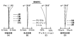
- 35 (A) to 35 (D) are graphs showing aberrations of the image pickup lens of Example 9 according to the present invention.
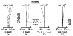
- 36 (A) to 36 (D) are graphs showing aberrations of the imaging lens according to Example 10 of the present invention.
- 37A to 37D are graphs showing aberrations of the imaging lens according to Example 11 of the present invention.
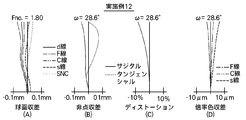
- FIGS. 38A to 38D are graphs showing aberrations of the image pickup lens of Example 12 of the present invention.
- 39A to 39D are diagrams showing aberrations of the imaging lens according to the thirteenth embodiment of the present invention.
- 40 (A) to 40 (D) are aberration diagrams of the imaging lens of Example 14 of the present invention.
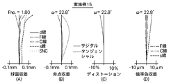
- 41 (A) to 41 (D) are graphs showing aberrations of the image pickup lens of Example 15 of the present invention.
- 42A to 42D are graphs showing aberrations of the imaging lens according to Example 16 of the present invention.
- 43 (A) to 43 (D) are graphs showing aberrations of the imaging lens according to Example 17 of the present invention.
- 44 (A) to 44 (D) are graphs showing aberrations of the imaging lens according to Example 18 of the present invention.
- 45A to 45D are aberration diagrams of the imaging lens of Example 19 of the present invention.
- 46 (A) to 46 (D) are graphs showing aberrations of the image pickup lens of Example 20 of the present invention.
- 47 (A) to 47 (D) are graphs showing aberrations of the image pickup lens of Example 21 of the present invention.
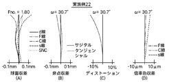
- 48 (A) to 48 (D) are graphs showing aberrations of the image pickup lens of Example 22 of the present invention.
- 49A to 49D are aberration diagrams of the image pickup lens of Example 23 of the present invention.
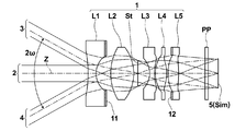
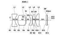
- FIG. 1 shows a lens cross-sectional view of an imaging lens 1 according to an embodiment of the present invention, an axial light beam 2 from an object point at an infinite distance, and off-axis light beams 3 and 4 at a full field angle 2 ⁇ . Indicates.
- the configuration example shown in FIG. 1 corresponds to an imaging lens of Example 1 described later.
- the left side of the figure is the object side
- the right side is the image side.
- the imaging element 5 disposed on the image plane Sim of the imaging lens 1 is also illustrated in consideration of the case where the imaging lens 1 is applied to an imaging apparatus.
- the image pickup device is simply illustrated, but actually, the image pickup surface of the image pickup device 5 is arranged so as to coincide with the position of the image plane Sim.
- the imaging device 5 converts an optical image formed by the imaging lens 1 into an electrical signal, and for example, a CCD image sensor or a CMOS image sensor can be used.
- the imaging lens 1 When the imaging lens 1 is applied to an imaging apparatus, it is preferable to provide various filters such as a cover glass, a low-pass filter, or an infrared cut filter according to the configuration on the camera side on which the lens is mounted.
- the parallel plate-like optical member PP assuming these is arranged between the lens closest to the image side and the image sensor 5 (image plane Sim).
- image plane Sim image plane Sim
- a cover glass and various filters are often disposed between the lens system and the image plane Sim, which is sufficient to dispose these in the lens system. Back focus is needed.
- the imaging lens 1 includes, in order from the object side along the optical axis Z, a negative first lens L1, a positive second lens L2, a negative third lens L3, and an object side. And a positive fourth lens L4 having a convex surface facing to the positive fifth lens L5, and an aperture stop St is disposed between the image side surface of the first lens L1 and the object side surface of the third lens L3.
- the lens system can be a retrofocus type lens system. It is easy to widen the angle and the back focus can be made long.
- the aperture stop St is arranged between the second lens L2 and the third lens L3, and in order from the object side, negative, positive, aperture stop St, negative, positive, positive power arrangement,
- the power on the object side and the image side of the aperture stop St can be made substantially equal, and the field curvature can be easily corrected.
- an aperture stop St is arranged between the first lens L1 and the second lens L2, and in order from the object side, negative, aperture stop St, positive, negative, positive, positive power arrangement and
- the light beam height in the first lens L1 can be suppressed, and the lens diameter of the portion exposed to the outside can be reduced, which is advantageous for downsizing.
- the exit pupil position can be brought to the object side, the angle at which the peripheral rays are incident on the image sensor 5 can be suppressed, shading can be suppressed, and the third lens L3 and the fourth lens L4.
- the fifth lens L5 the on-axis light beam and the off-axis light beam can be easily separated, and the field curvature can be easily corrected.
- the aperture stop St may be arranged so that the position of the aperture stop St in the optical axis direction is between the object-side surface vertex and the image-side surface vertex of the second lens L2.
- the positive power arranged closest to the image side is divided into two lenses, the fourth lens L4 and the fifth lens L5, so that the spherical aberration can be easily corrected, and even in a lens system having a small F-number. Aberration can be corrected satisfactorily.
- the angle at which peripheral rays enter the image sensor can be reduced while suppressing chromatic aberration, and the telecentricity is good.
- a lens system can be realized.
- the object side surface of the first lens L1 concave, it is possible to increase the negative power of the first lens L1, and it is easy to widen the angle and to achieve a long back focus.
- the object side surface of the fourth lens L4 convex it is possible to increase the positive power of the fourth lens L4, and to easily correct chromatic aberration favorably while cooperating with the third lens L3. Become.
- the imaging lens 1 shown in FIG. 1 includes first, second, and third modes described below in addition to the above basic configuration.
- the first mode satisfies the following conditional expression (1), where f is the focal length of the entire system and f1 is the focal length of the first lens L1. -1.25 ⁇ f1 / f ⁇ -0.5 (1)
- conditional expression (1) If the upper limit of conditional expression (1) is exceeded, the power of the first lens L1 becomes too strong, making it difficult to correct the curvature of field, the back focus becomes too long, and the lens system can be downsized. It becomes difficult. Below the lower limit of conditional expression (1), the power of the first lens L1 becomes too weak, making it difficult to widen the angle and secure the back focus.
- the focal length of the entire system is f
- the focal length of the second lens L2 is f2
- the radius of curvature of the object side surface of the first lens L1 is R1
- the image side of the first lens L1 is on the image side.
- conditional expression (2) If the upper limit of conditional expression (2) is exceeded, the power of the second lens L2 becomes weak, making it difficult to correct field curvature, and the aperture stop St is disposed between the second lens L2 and the third lens L3. If this is the case, the power balance between the object side and the image side of the aperture stop St is lost, making it difficult to correct coma. If the lower limit of conditional expression (2) is not reached, the power of the second lens L2 becomes too strong, and the tolerance for errors related to decentration becomes small, which makes manufacturing difficult or causes an increase in cost.
- (R1 + R2) / (R1-R2) is a positive value and is 1.0 or less because the first lens L1 is a biconcave lens and the absolute value of the radius of curvature of the object side surface is an image.
- the absolute value of the curvature radius of the side surface is larger than the absolute value of the curvature radius of the object side surface or the absolute value of the curvature radius of the image side surface of the biconvex lens.
- the first lens L1 is a biconvex lens, it becomes a positive lens, and the first lens L1 is contrary to the basic configuration of a negative lens. Therefore, in order to satisfy the conditional expression (3), the curvature of the object side surface with the biconcave lens This is the case when the absolute value of the radius is larger than the absolute value of the radius of curvature of the image side surface.
- conditional expression (3) If the upper and lower limits of conditional expression (3) are not satisfied, spherical aberration will be undercorrected or overcorrected, and a good image cannot be obtained. If the upper limit of conditional expression (3) is exceeded, it will be difficult to correct field curvature. If the lower limit of conditional expression (3) is not reached, it becomes a biconcave lens in which the difference in absolute value of the radius of curvature between the object-side surface and the image-side surface of the first lens L1 is small, making it difficult to correct spherical aberration and coma aberration. It becomes.
- the third aspect is that the following conditional expression (4) is satisfied, where f is the focal length of the entire system and f5 is the focal length of the fifth lens L5. 0.99 ⁇ f5 / f ⁇ 2.10 (4)
- each of the imaging lenses having the first, second, and third aspects has a configuration described below.
- it may have any one of the following configurations, or may have a configuration in which any two or more are combined.
- conditional expression (5) If the upper limit of conditional expression (5) is exceeded, the distance between the second lens L2 and the third lens L3 becomes too large, making it difficult to reduce the overall length, and reducing the lens diameter of the first lens L1. It becomes difficult. If the lower limit of conditional expression (5) is not reached, the distance between the second lens L2 and the third lens L3 becomes too small, and it becomes difficult to correct field curvature and coma well.
- the fifth lens L5 has a radius of curvature between the object-side surface and the image-side surface.
- Biconvex lens the curvature radius of the object-side surface is smaller than the curvature radius of the image-side surface
- a biconcave lens the curvature of the object-side surface having a close curvature radius between the object-side surface and the image-side surface The radius is smaller than the radius of curvature of the image side surface. Since the biconcave lens is a negative lens, the fifth lens L5 is contrary to the basic configuration requirement that it is a positive lens. For this reason, the upper limit of conditional expression (6) is exceeded in the case of a biconvex lens having a curvature radius close to that of the object side surface and the image side surface. It becomes difficult.
- the fifth lens L5 is a negative meniscus lens having a convex surface facing the image side or a positive meniscus lens having a convex surface facing the object side.
- the fifth lens L5 is based on the basic configuration requirement of a positive lens.
- the case where the fifth lens L5 is a positive meniscus lens having a convex surface facing the object side will be considered.
- the fifth lens L5 is a positive meniscus lens having a convex surface facing the object side and falls below the lower limit of conditional expression (6)
- the difference in the radius of curvature between the object side surface and the image side surface of the fifth lens L5 is Since the power becomes too small and the positive power becomes weak, the power balance between the fourth lens L4 and the fifth lens L5 becomes poor and it becomes difficult to correct spherical aberration, or the radius of curvature of the object side surface of the fifth lens L5 Becomes too small, and it becomes difficult to correct curvature of field and coma.
- conditional expression (7) If the upper limit of conditional expression (7) is exceeded, the negative power of the first lens L1 becomes too strong compared to the positive power of the second lens L2, and it becomes easy to widen the angle. It becomes difficult to correct aberrations. Below the lower limit of conditional expression (7), the positive power of the second lens L2 becomes too strong compared to the negative power of the first lens L1, making it difficult to widen the angle and secure the back focus.
- the power of the fourth lens L4 becomes too weak, making it difficult to correct chromatic aberration well in cooperation with the third lens, or the power of the fourth lens L4. Becomes too weak, the power balance with the fifth lens L5 becomes poor, and correction of spherical aberration becomes difficult. If the lower limit of conditional expression (8) is not reached, the power of the fourth lens L4 becomes too strong, so that the balance of power with the fifth lens L5 becomes poor, and it becomes difficult to correct spherical aberration.
- conditional expression (9) If the upper limit of conditional expression (9) is exceeded, the distance between the first lens L1 and the second lens L2 becomes too large, the diameter of the first lens L1 becomes large, and it becomes difficult to achieve miniaturization. . If the lower limit of conditional expression (9) is not reached, the first lens L1 and the second lens L2 are too close together, making it difficult to increase the back focus.
- conditional expression (10) If the upper limit of conditional expression (10) is exceeded, the power of the fourth lens L4 and the fifth lens L5 becomes weak, or the power of the third lens L3 becomes too strong, and the angle at which the lens system enters the image sensor 5 It is difficult to suppress the lens, and it becomes difficult to manufacture a lens with good telecentricity. Below the lower limit of conditional expression (10), it becomes difficult to correct field curvature and coma well.
- conditional expression (11) If the upper limit of conditional expression (11) is exceeded, the total length of the optical system becomes long and the objective of miniaturization cannot be achieved. Below the lower limit of conditional expression (11), it becomes difficult to correct coma and field curvature.
- f12 is a positive value.
- conditional expression (12) If the upper limit of conditional expression (12) is exceeded, the absolute value of the radius of curvature of the object-side surface of the first lens L1 becomes too small, and widening is easy, but it is difficult to suppress distortion and curvature of field. It becomes. If the lower limit of conditional expression (12) is not reached, the absolute value of the radius of curvature of the object-side surface of the first lens L1 will increase, making it difficult to correct spherical aberration, or reducing the size of the first lens L1 in the radial direction. It becomes difficult.
- conditional expression (13) If the upper limit of conditional expression (13) is exceeded, the power of the third lens L3 becomes too strong, making it difficult to suppress the angle of incidence from the lens system to the image sensor 5 and making a lens with good telecentricity. It becomes difficult. If the lower limit of conditional expression (13) is not reached, the power of the third lens L3 becomes too weak, making it difficult to correct chromatic aberration.
- conditional expression (14) If the upper limit of conditional expression (14) is exceeded, the lens system becomes large. If the lower limit of conditional expression (14) is not reached, downsizing can be easily achieved, but widening becomes insufficient or the overall length becomes too short, and downsizing is easy but the thickness of each lens is reduced. Therefore, it becomes difficult to manufacture or causes an increase in cost.
- L is preferably 22 mm or less. If L exceeds 22 mm, the lens system becomes large, and the objective of size reduction cannot be achieved.
- L is more preferably 20 mm or less, and L is still more preferably 19 mm or less.
- conditional expressions satisfy the following changes in the lower and upper limits.
- each conditional expression configured by combining the lower limit change value and the upper limit change value described below may be satisfied.
- conditional expression (1) As the lower limit change value of conditional expression (1), ⁇ 1.20 is preferable, ⁇ 1.15 is more preferable, and ⁇ 1.10 is even more preferable.
- the upper limit change value of conditional expression (1) is preferably ⁇ 0.55, more preferably ⁇ 0.6, and even more preferably ⁇ 0.8.
- conditional expression (1-2) instead of the conditional expression (1), and it is more preferable to satisfy the following conditional expression (1-3).
- conditional expression (1-3) -1.15 ⁇ f1 / f ⁇ -0.55 (1-2) ⁇ 1.10 ⁇ f1 / f ⁇ 0.60 (1-3)
- conditional expression (2) As the lower limit change value of conditional expression (2), 0.6 is preferable, 0.7 is more preferable, and 0.8 is even more preferable. As an upper limit change value of conditional expression (2), 1.3 is preferable, and 1.2 is more preferable.
- conditional expression (3) As a lower limit change value of conditional expression (3), 0.2 is preferable, 0.4 is more preferable, and 0.6 is even more preferable. As an upper limit change value of conditional expression (3), 0.90 is preferable, 0.86 is more preferable, and 0.79 is even more preferable.
- conditional expression (4) As the lower limit change value of conditional expression (4), 1.00 is preferable, 1.20 is more preferable, and 1.30 is even more preferable. As a change value of the upper limit of conditional expression (4), 2.05 is preferable and 1.98 is more preferable.
- conditional expression (5) As a lower limit change value of conditional expression (5), 0.20 is preferable, 0.25 is more preferable, 0.27 is still more preferable, and 0.30 is still more preferable. As a change value of the upper limit of conditional expression (5), 0.62 is preferable, 0.61 is more preferable, and 0.60 is even more preferable.
- conditional expression (6) As the lower limit change value of conditional expression (6), ⁇ 1.30 is preferable, and ⁇ 1.20 is more preferable.
- the upper limit change value of conditional expression (6) is preferably ⁇ 0.3, more preferably ⁇ 0.4.
- conditional expression (7) As the lower limit change value of conditional expression (7), -1.25 is preferable, -1.20 is more preferable, and -1.15 is even more preferable.
- the upper limit change value of conditional expression (7) is preferably -0.75, more preferably -0.85, and even more preferably -0.90.
- conditional expression (8) As a lower limit change value of conditional expression (8), 0.7 is preferable, 0.8 is more preferable, and 0.9 is even more preferable. As an upper limit change value of conditional expression (8), 1.5 is preferable, 1.25 is more preferable, and 1.20 is even more preferable.
- conditional expression (9) As the lower limit change value of conditional expression (9), 0.2 is preferable.
- the upper limit change value of conditional expression (9) is preferably 0.51.
- conditional expression (10) As a lower limit change value of the conditional expression (10), 1.3 is preferable, and 1.4 is more preferable.
- the upper limit change value of conditional expression (10) is preferably 2.5, more preferably 2.4, even more preferably 2.3, and even more preferably 2.25.
- conditional expression (11) As a lower limit change value of conditional expression (11), 0.1 is preferable, 0.2 is more preferable, and 0.3 is even more preferable. As an upper limit change value of conditional expression (11), 1.5 is preferable, 1.3 is more preferable, and 1.2 is even more preferable.
- conditional expression (12) As the lower limit change value of conditional expression (12), ⁇ 6.0 is preferable, ⁇ 5.5 is more preferable, and ⁇ 5.2 is even more preferable.
- the upper limit change value of conditional expression (12) is preferably -1.0, more preferably -1.5, and even more preferably -1.7.
- conditional expression (13) As the lower limit change value of conditional expression (13), -1.2 is preferable, -1.1 is more preferable, -1.0 is still more preferable, and -0.9 is still more preferable.
- the upper limit change value of conditional expression (13) is preferably ⁇ 0.3, more preferably ⁇ 0.4, and even more preferably ⁇ 0.45.
- conditional expression (14) As a lower limit change value of conditional expression (14), 2.8 is preferable, 3.0 is more preferable, and 3.4 is even more preferable. As an upper limit change value of conditional expression (14), 4.8 is preferable, 4.6 is more preferable, and 4.5 is even more preferable.
- ⁇ d1 is preferably 40 or more, and thus axial chromatic aberration can be corrected well.
- ⁇ d1 is more preferably 45 or more, even more preferably 55 or more, and even more preferably 60 or more.
- ⁇ d2 is preferably 35 or more, whereby axial chromatic aberration can be corrected well.
- ⁇ d2 is more preferably 40 or more, and even more preferably 45 or more.
- ⁇ d3 is preferably smaller than 35, which makes it possible to satisfactorily correct axial chromatic aberration and lateral chromatic aberration.
- ⁇ d3 is more preferably less than 30, even more preferably less than 27, and even more preferably less than 26.
- ⁇ d3 is preferably greater than 15 and more preferably greater than 20.
- ⁇ d4 is preferably 40 or more, so that axial chromatic aberration can be corrected well.
- ⁇ d4 is more preferably 45 or more, and even more preferably 52 or more.
- ⁇ d5 is preferably 40 or more, and thus axial chromatic aberration can be corrected well.
- ⁇ d5 is more preferably 45 or more, and even more preferably 52 or more.
- Nd1 is preferably 1.80 or less.
- Nd1 is more preferably 1.65 or less, and even more preferably 1.60 or less.
- Nd1 is preferably 1.46 or more.
- Nd1 is smaller than 1.46, it is possible to select a material with a large Abbe number and suppress the occurrence of chromatic aberration.
- the degree of wear of the material is high and the material becomes soft, for example, When used as an in-vehicle camera lens or a surveillance camera lens, the weather resistance is insufficient.
- Nd1 is more preferably 1.50 or more.
- Nd2 is preferably 1.72 or more, which makes it easy to increase the power of the second lens L2 and to reduce the curvature of field. Correction is easy.
- Nd2 is more preferably 1.75 or more, and even more preferably 1.80 or more.
- Nd3 is preferably smaller than 1.75, so that the third lens L3 can be manufactured at low cost, and the cost of the entire lens system is reduced. Can be lowered.
- Nd3 is more preferably less than 1.70, even more preferably less than 1.68, and even more preferably less than 1.66.
- the negative third lens L3 has a function of enhancing telecentricity while suppressing chromatic aberration in cooperation with the positive fourth lens L4 and the fifth lens L5, and thus the third lens L3 and the fourth lens.
- Nd3 is preferably greater than 1.55, and more preferably greater than 1.59.
- Nd4 is preferably 1.68 or less.
- Nd4 is greater than 1.68, the power of the fourth lens L4 becomes strong, and the power balance with the fifth lens L5 is lost, making it difficult to correct spherical aberration, or the third lens L3 and the fourth lens.
- plastic is used for the material of L4 and the fifth lens L5, the balance between the negative power of the third lens L3 and the positive power of the fourth lens L4 and the fifth lens L5 is lost, and the focus shifts when the temperature changes. The amount will increase. Alternatively, it becomes difficult to select a material having a large Abbe number from currently available optical materials, and it is difficult to correct chromatic aberration.
- Nd5 is preferably 1.68 or less.
- Nd5 is greater than 1.68, the power of the fifth lens L5 becomes strong, and the power balance with the fourth lens L4 is lost, making it difficult to correct spherical aberration, or the third lens L3 and the fourth lens.
- plastic is used for the material of L4 and the fifth lens L5, the balance between the negative power of the third lens L3 and the positive power of the fourth lens 14 and the fifth lens L5 is lost, and the focus shifts when the temperature changes. The amount will increase. Alternatively, it becomes difficult to select a material having a large Abbe number from currently available optical materials, and it is difficult to correct chromatic aberration.
- the first lens L1 is preferably a biconcave lens, and according to such a configuration, the negative power of the first lens L1 can be increased, which is advantageous for widening the angle and easily achieving a long back focus. It becomes.
- the second lens L2 is preferably a biconvex lens. According to such a configuration, the power of the second lens L2 can be increased, and even when the power of the first lens L1 is increased for widening the angle, It becomes easy to increase the power of the second lens L2, and the aberration generated in the first lens L1 of the negative lens can be canceled out by the aberration generated in the second lens L2 of the positive lens, so that spherical aberration, coma aberration, image Correction of surface curvature is facilitated.
- the third lens L3 is preferably a biconcave lens. According to such a configuration, the power of the third lens L3 can be increased, and axial chromatic aberration and lateral chromatic aberration can be easily corrected.
- the fourth lens L4 is preferably a biconvex lens. According to such a configuration, the power of the fourth lens L4 can be increased, and chromatic aberration can be favorably corrected in cooperation with the third lens L3. It becomes easy.
- the fifth lens L5 is preferably a lens having a convex surface directed toward the object side, and according to such a configuration, correction of field curvature becomes easy.
- the fifth lens L5 is a biconvex lens, it becomes easy to correct curvature of field.
- the fifth lens L5 is a meniscus lens having a convex surface directed toward the object side, it is easy to correct spherical aberration.
- the preferable surface shapes of the first lens L1 to the fifth lens L5 described above are considered in the paraxial region when each lens is an aspherical lens.
- the third lens L3 preferably has an aspheric surface on at least one of the object side and the image side, whereby it is possible to satisfactorily correct axial chromatic aberration and lateral chromatic aberration as well as spherical aberration and field curvature. It becomes easy.
- the center of each lens surface that is, the intersection between the surface and the optical axis Z is Ci (i is equivalent to the surface number described in the description of the embodiments described later), and a certain point on the lens surface.
- Is Xi, and the intersection of the normal of the lens surface at the point Xi and the optical axis Z is Pi
- the power at the point Xi indicates whether the point Pi is on the object side or the image side of the point Ci.
- the aspheric surface is an object side surface
- the power at the point Xi is positive when the point Pi is closer to the image side than the point Ci
- the point Xi when the point Pi is closer to the object side than the point Ci. Power is defined as negative power.
- the power at the point Xi is positive when the point Pi is closer to the object side than the point Ci, and the point when the point Pi is closer to the image side than the point Ci.
- the power at Xi is defined as negative power.
- the line segment connecting the point Xi and the point Pi is defined as the radius of curvature RXi at the point Xi, and the absolute value of RXi
- the shape where the power is weaker than the center at the point Xi is a shape where
- a shape having a stronger power than the center at the point Xi is a shape in which
- the general description of the aspherical surface is applicable to any aspherical lens surface of the imaging lens.
- Ci, Xi, Pi, RXi, and Ri in the above description are symbols used for convenience of description, and are not limited.
- the point Xi in the above description can be an arbitrary point on the lens surface, and can be considered as, for example, an axial ray diameter end point or an effective diameter end point.
- the object-side surface of the third lens L3 is preferably an aspheric surface, which facilitates correction of spherical aberration and field curvature. It is preferable that the object side surface of the third lens L3 has a negative power at the center and has a shape in which the negative power is weaker at the axial ray end than at the center. By making the object side surface of the third lens L3 into such a shape, it becomes easy to correct spherical aberration and curvature of field.
- FIG. 2 shows a cross-sectional view of the third lens L3 and the axial light beam 2, and illustration of other lenses is omitted to avoid complication of the drawing. That is, the on-axis light beam 2 shown in FIG. 2 is in the imaging lens 1 when the first lens L1 to the fifth lens L5 are present.
- the point C3F is the center of the object side surface of the third lens L3, and is the intersection of the object side surface of the third lens L3 and the optical axis Z.
- a point XA3F in FIG. 2 is a point on the axial ray diameter end of the object side surface of the third lens L3, and is an intersection of the outermost ray of the axial beam 2 and the object side surface of the third lens L3. is there.
- the intersection of the normal of the lens surface at the point XA3F and the optical axis Z is defined as a point PXA3F as shown in FIG.
- a line segment connecting the point XA3F and the point PXA3F is defined as a curvature radius RXA3F at the point XA3F, and the length of this line segment is defined as an absolute value
- the radius of curvature at the point C3F that is, the radius of curvature of the center of the object side surface of the third lens L3 is L3F
- the absolute value thereof is
- Having negative power at the center” on the object side surface of the third lens L3 means that the paraxial region including the point C3F is concave. Further, “the shape where the negative power is weaker than the center at the end of the axial ray diameter” on the object side surface of the third lens L3 is that the point PXA3F is closer to the object side than the point C3F, and
- a circle CC3F centered on the point O3F on the optical axis is drawn with a two-dot chain line with a radius
- a circle CX3F centered on the upper point PXA3F is drawn with a broken line.
- the circle CX3F is larger than the circle CC3F, and it is clearly indicated that
- the surface of the object of the third lens L3 has a negative power at the center and has a shape with a weaker negative power than the center at the effective diameter end.
- the “effective diameter of the surface” is a circle consisting of the outermost point in the radial direction (the point farthest from the optical axis) when the point where all the rays that contribute to image formation intersect with the lens surface is considered. It means the diameter, and “effective diameter end” means the outermost point.
- the figure composed of the outermost points is a circle.
- the circle diameter may be considered as the effective diameter.
- the effective diameter can be determined based on the size of the imaging surface of the image sensor, and when the image surface is rectangular, for example, 1/2 of the diagonal length thereof. Can be calculated as the maximum image height.
- the image side surface of the third lens L3 is preferably an aspheric surface, which facilitates correction of spherical aberration and curvature of field.
- the image-side surface of the third lens L3 has a negative power at the center, and the negative power is weaker than the center at the axial ray diameter end, or the center has a negative power and the axial ray diameter. It is preferable to have positive power at the edges.
- the image side surface of the third lens L3 has a negative power at the center, and has a shape in which the negative power is weaker than the center at the effective diameter end, or has a negative power at the center, and at the effective diameter end.
- a shape having a positive power is preferable.
- the fourth lens L4 preferably has at least one of the object side and the image side as an aspheric surface, so that it can satisfactorily correct axial chromatic aberration and lateral chromatic aberration as well as spherical aberration and field curvature. It becomes easy.
- the object-side surface of the fourth lens L4 is preferably an aspherical surface, which facilitates correction of spherical aberration. It is preferable that the object-side surface of the fourth lens L4 has a positive power at the center and has a weaker positive power at the axial ray end than the center. By making the object side surface of the fourth lens L4 in such a shape, it becomes easy to correct spherical aberration and curvature of field.
- the object side surface of the fourth lens L4 has a positive power at the center and a shape with a weak positive power at the effective diameter end as compared with the center.
- the image-side surface of the fourth lens L4 is preferably an aspherical surface, which facilitates correction of spherical aberration.
- the image side surface of the fourth lens L4 has a positive power at the center, and has a shape in which the positive power is weaker than the center at the axial ray end, or has a positive power at the center, and at the axial ray end.
- a shape having a negative power is preferable.
- the image side surface of the fourth lens L4 has a positive power at the center, and has a shape in which the positive power is weaker than the center at the effective diameter end, or has a positive power at the center, and at the effective diameter end.
- a shape having a negative power is preferable.
- the fifth lens L5 preferably has an aspheric surface on at least one of the object side and the image side. This makes it easy to satisfactorily correct spherical aberration, coma aberration, and field curvature, Telecentricity can be improved.
- the object-side surface of the fifth lens L5 is preferably an aspherical surface, which facilitates correction of coma and field curvature. It is preferable that the object-side surface of the fifth lens L5 has a positive power at the center and a shape with a stronger positive power than the center at the axial ray end. By making the object-side surface of the fifth lens L5 in this shape, coma and field curvature can be easily corrected and telecentricity can be improved.
- the object side surface of the fifth lens L5 has a positive power at the center and a shape having a stronger positive power than the center at the effective diameter end.
- the image-side surface of the fifth lens L5 is preferably an aspheric surface, which facilitates correction of spherical aberration.
- the image side surface of the fifth lens L5 has a positive power at the center, and has a shape in which the positive power is weaker than the center at the axial ray end, or has a positive power at the center, and at the axial ray end.
- a shape having a negative power is preferable.
- the image-side surface of the fifth lens L5 has a positive power at the center, and has a shape in which the positive power is weaker than the center at the effective diameter end, or has a positive power at the center, and at the effective diameter end.
- a shape having a negative power is preferable.
- the distortion is preferably ⁇ 10% or less. An image with little distortion can be obtained.
- the imaginary height is represented by f ⁇ tan ( ⁇ )
- all lenses constituting the lens system are not cemented.
- the lens system when used as an in-vehicle lens, the lens system is required to have high heat resistance and environmental resistance.
- a cemented lens When a cemented lens is used, a special cement is used to increase the heat resistance and the environment resistance, and a process for increasing the environment resistance is required, resulting in high costs. Therefore, it is preferable that all of the first lens L1 to the fifth lens L5 are single lenses.
- the first lens L1 disposed closest to the object side is resistant to surface deterioration due to wind and rain, temperature change due to direct sunlight,
- materials that are resistant to chemicals such as oils and detergents, that is, materials with high water resistance, weather resistance, acid resistance, chemical resistance, etc.
- materials that are hard and hard to break are required to use materials that are hard and hard to break.
- glass is required to be used as the material.
- the first lens L1 is preferably a glass spherical lens, but may be a glass aspherical lens when high optical performance is important.
- a protective means for enhancing the strength, scratch resistance and chemical resistance may be applied to the object side surface of the first lens L1, and in this case, the material of the first lens L1 may be plastic.
- Such protective means may be a hard coat or a water repellent coat.
- the material of the second lens L2 is preferably glass.
- the range of selection of the refractive index of the second lens L2 is widened, and the refractive index of the second lens L2 can be increased.
- the refractive index of the second lens L2 it is easy to increase the power of the second lens L2, and it becomes easy to correct field curvature.
- the material of the second lens L2 may be plastic.
- the second lens L2 By making the second lens L2 a plastic lens, it becomes possible to create a lens system at low cost, and when an aspheric surface is used for the second lens, it becomes easy to accurately reproduce the aspheric shape, It becomes possible to create a high-performance lens.
- the material of the third lens L3 is preferably plastic, which makes it easy to accurately produce an aspheric shape, facilitates ensuring good optical performance, and is advantageous for cost reduction and weight reduction. Become.
- the material of the fourth lens L4 is preferably plastic, which makes it easy to accurately produce an aspheric shape, facilitates ensuring good optical performance, and is advantageous for cost reduction and weight reduction. Become.
- the material of the fifth lens L5 is preferably plastic, which makes it easy to accurately produce an aspheric shape, facilitates ensuring good optical performance, and is advantageous for cost reduction and weight reduction. Become.
- the plastic lens has a drawback that the amount of movement of the focal position is large when the temperature changes, but by using the third lens L3, the fourth lens L4, and the fifth lens L5 as plastic lenses, the focal point by the positive lens when the temperature changes. Since the amount of movement of the position and the amount of movement of the focal position by the negative lens can be offset, performance degradation due to temperature changes can be suppressed.
- the imaging lens When the imaging lens is used as, for example, an in-vehicle camera, it is desired that the imaging lens can be used in a wide temperature range from the outside air in a cold region to the interior of a tropical summer car. For example, under such severe conditions, all lenses may be made of glass.
- the third lens L3, the fourth lens L4, and the fifth lens L5 as glass lenses, a lens system with high heat resistance can be realized.
- a specific wavelength region such as a UV (Ultra Violet) cut filter or an IR (InfraRed) cut filter is blocked, transmitted, or reflected between the lens system and the imaging device 5.
- Various filters may be inserted.
- a coat having the same function as such a filter may be applied to the lens surface.
- a material that absorbs ultraviolet light, blue light, infrared light, or the like may be used as a material of any lens.
- the lens system is composed of only five lenses of the first lens L1, the second lens L2, the third lens L3, the fourth lens L4, and the fifth lens L5. This makes it possible to reduce the cost of the lens system while maintaining good optical performance.
- FIG. 1 shows an example in which the optical member PP assuming various filters and the like is arranged between the lens system and the image sensor 5. Instead, these various filters are arranged between the lenses. May be.
- a light shielding means for shielding the stray light as necessary.
- the light shielding means for example, an opaque paint may be applied to a portion outside the effective diameter of the lens, or an opaque plate material may be provided.
- an opaque plate material may be provided in the optical path of a light beam that becomes stray light to serve as a light shielding unit.
- a hood that blocks stray light may be disposed further on the object side of the most object side lens. As an example, FIG.
- the light shielding means 11 is provided outside the effective diameter of the image side surface of the first lens L1.
- the location where the light shielding means is provided is not limited to the example shown in FIG. 1, and may be arranged between other lenses or between the lenses.
- a member such as a diaphragm that blocks the peripheral light beam may be disposed between the lenses so long as the peripheral light amount ratio has no practical problem.
- a peripheral ray is a ray that passes through a peripheral portion of the entrance pupil of the optical system among rays from an object point outside the optical axis Z.
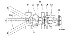
- the imaging lens of the present invention does not necessarily require the light shielding member that shields the peripheral light as described above.
- the configuration diagram of the imaging lens 10 in FIG. A configuration without using a member is also possible, and good optical performance can be obtained even with such a configuration.
- the imaging lens 10 shown in FIG. 3 corresponds to Example 11 described later.
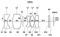
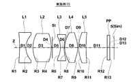
- FIGS. 4 to 26 Lens cross-sectional views of the imaging lenses of Examples 1 to 23 are shown in FIGS. 4 to 26, respectively. 4 to 26, the left side of the figure is the object side, the right side is the image side, and the aperture stop St and the optical member PP are also illustrated.
- the aperture stop St in each figure does not indicate the shape or size, but indicates the position on the optical axis Z.
- Tables 1 to 23 show lens data of the imaging lenses of Examples 1 to 23, respectively.
- (A) shows basic lens data
- (B) shows various data
- (C) shows aspherical data.
- the column indicates the radius of curvature of the i-th surface
- the column Di indicates the surface interval on the optical axis Z between the i-th surface and the i + 1-th surface.
- the sign of the radius of curvature is positive when the surface shape is convex on the object side and negative when the surface shape is convex on the image side.
- the refractive index with respect to the d-line (wavelength: 587.6 nm) of the j-th (j 1, 2, 3,%) Optical element that sequentially increases toward the image side with the most object-side lens as the first.
- the column of ⁇ dj indicates the Abbe number for the d-line of the jth optical element.
- the basic lens data includes the aperture stop St and the optical member PP, and the word “aperture stop” is also described in the column of the radius of curvature of the surface corresponding to the aperture stop St. .
- L in Air
- Bf in Air
- the distance on the optical axis Z from the image side surface of the lens to the image plane Sim (corresponding to back focus, air conversion length)
- f is the focal length of the entire system
- f1 is the focal length of the first lens L1
- f2 is The focal length of the second lens L2
- f3 is the focal length of the third lens L3
- f4 is the focal length of the fourth lens L4
- f5 is the focal length of the fifth lens L5
- f12 is the distance between the first lens L1 and the second lens L2.
- a combined focal length, f345, is a combined focal length from the third lens L3 to the fifth lens L5.
- the imaging lenses of Examples 1, 3, 6, 7, and 23 are designed assuming that a vignetting diaphragm that is a light shielding unit that shields ambient light and stray light is provided.
- the surface number and the radius are provided as the vignetting surface number and the vignetting aperture diameter, respectively.
- the surface number of the aspheric surface is marked with *, and the value of the paraxial curvature radius (center curvature radius) is shown as the curvature radius of the aspheric surface.
- the aspheric data shows the surface number of the aspheric surface and the aspheric coefficient for each aspheric surface.
- the numerical value “E ⁇ n” (n: integer) of the aspheric surface data means “ ⁇ 10 ⁇ n ”, and “E + n” means “ ⁇ 10 n ”.
- Zd Depth of aspheric surface (length of perpendicular drawn from a point on the aspherical surface of height Y to a plane perpendicular to the optical axis where the aspherical vertex contacts)
- Y Height (distance from the optical axis to the lens surface)
- the first lens L1 and the second lens L2 are glass spherical lenses
- the third lens L3, the fourth lens L4, and the fifth lens L5 are plastic aspheric lenses.
- Table 24 shows values corresponding to the conditional expressions (1) to (14) in the imaging lenses of Examples 1 to 23.
- the d-line is used as a reference wavelength, and Table 24 shows values at this reference wavelength.
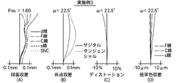
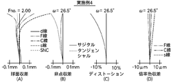
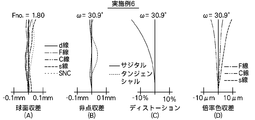
- the aberration diagrams of Example 1 will be described as an example, but the same applies to the aberration diagrams of other Examples.
- 27 (A), 27 (B), 27 (C), and 27 (D) are respectively spherical aberration, astigmatism, distortion (distortion aberration), and lateral chromatic aberration (for the imaging lens according to Example 1).
- the aberration diagram of chromatic aberration of magnification) is shown.
- Fno Of spherical aberration diagram. Means F value, and ⁇ in other aberration diagrams means half angle of view.
- the distortion diagram shows the amount of deviation from the ideal image height f ⁇ tan ( ⁇ ) using the focal length f and angle of view ⁇ (variable treatment, 0 ⁇ ⁇ ⁇ ⁇ ) of the entire system.
- Each aberration diagram shows aberrations with the d-line (587.56 nm) as the reference wavelength, while the spherical aberration diagram shows the F-line (wavelength 486.13 nm), C-line (wavelength 656.27 nm), and s-line ( The aberration for the sine condition violation amount (denoted as SNC) is also shown, and the magnification chromatic aberration diagram shows the aberration for the F-line, C-line, and s-line. Since the line type of the chromatic aberration diagram of magnification is the same as that of the spherical aberration diagram, the description is omitted.
- the imaging lenses of Examples 1 to 23 are small and inexpensive, have a small F number of 1.60 to 2.00, and a total angle of view of 45.0 ° to 65.4. It has a sufficiently long back focus, various aberrations are well corrected, and good optical performance.
- These imaging lenses can be suitably used for surveillance cameras, in-vehicle cameras for taking images of the front, side, rear, etc. of automobiles.
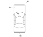
- FIG. 50 shows a state in which an imaging apparatus including the imaging lens of the present embodiment is mounted on the automobile 100.
- an automobile 100 includes an on-vehicle camera 101 for imaging a blind spot range on the side surface on the passenger seat side, an on-vehicle camera 102 for imaging a blind spot range on the rear side of the automobile 100, and a rear surface of a rearview mirror.
- An in-vehicle camera 103 is attached and is used for photographing the same field of view as the driver.
- the outside camera 101, the outside camera 102, and the inside camera 103 are imaging devices according to the embodiment of the present invention.
- An imaging lens according to the embodiment of the present invention and an optical image formed by the imaging lens are used as electrical signals.
- An image sensor for conversion.
- the imaging lens according to the embodiment of the present invention has the above-described advantages, the outside cameras 101 and 102 and the in-vehicle camera 103 can be configured to be small and inexpensive, and can be used even under low illumination conditions. A good image with high resolution can be obtained using the image sensor.
- the present invention has been described with reference to the embodiments and examples. However, the present invention is not limited to the above-described embodiments and examples, and various modifications can be made.
- the values of the radius of curvature, the surface interval, the refractive index, the Abbe number, and the aspheric coefficient of each lens component are not limited to the values shown in the above numerical examples, and can take other values.
- the present invention is not limited to this application, and for example, a mobile terminal camera or a surveillance camera The present invention can also be applied.
Abstract
[Problem] To implement a small, inexpensive, highly telecentric, high-performance imaging lens with a long back focal length and small F-number. [Solution] An imaging lens (1) is provided with the following lenses, in order from the object side: a negative first lens (L1) that is concave towards the object side; a positive second lens (L2); a negative third lens (L3); a positive fourth lens (L4) that is convex towards the object side; and a positive fifth lens (L5). An aperture is disposed between the image-side surface of the first lens (L1) and the object-side surface of the third lens (L3).The focal length (f) of the entire system and the focal length (f1) of the first lens (L1) satisfy relation (1).
(1) −1.25 < f1/f < −0.5
Description
本発明は、撮像レンズおよび撮像装置に関し、より詳しくは、CCD(Charge Coupled Device)やCMOS(Complementary Metal Oxide Semiconductor)等の撮像素子を用いた車載用カメラ、携帯端末用カメラ、監視カメラ等に使用されるのに好適な撮像レンズ、および該撮像レンズを備えた撮像装置に関するものである。
The present invention relates to an imaging lens and an imaging apparatus, and more specifically, to an in-vehicle camera, a mobile terminal camera, a monitoring camera, and the like using an imaging element such as a CCD (Charge Coupled Device) or a CMOS (Complementary Metal Oxide Semiconductor). The present invention relates to an imaging lens suitable for the imaging, and an imaging device including the imaging lens.
CCDやCMOS等の撮像素子は近年非常に小型化及び高画素化が進んでいる。それとともに、これら撮像素子を備えた撮像機器本体も小型化が進み、それに搭載される撮像レンズにも良好な光学性能に加え、小型化が求められている。一方、車載用カメラや監視カメラ等に搭載されるレンズでは、小型化とともに、高い耐候性を有し、軽量で安価に構成可能で、低照度の撮影条件下でも使用可能なようにF値が小さいことが求められている。
In recent years, image sensors such as CCD and CMOS have been greatly reduced in size and pixels. At the same time, an image pickup apparatus body including these image pickup elements is also downsized, and an image pickup lens mounted thereon is required to be downsized in addition to good optical performance. On the other hand, lenses mounted on in-vehicle cameras, surveillance cameras, etc. have a small F, high weather resistance, can be configured at a low cost, and have an F value so that they can be used even under low illumination conditions. It is required to be small.
下記特許文献1には、車載用カメラや監視カメラ等に使用可能で、最も物体側のレンズが物体側に凸面を向けた負メニスカスレンズであり、5枚のレンズからなる撮像レンズが記載されている。下記特許文献2には、小型のCCDが搭載されたカメラに使用可能で、非球面レンズを含む、5枚のレンズからなる撮像レンズが記載されている。
Patent Document 1 below describes an imaging lens that can be used for an in-vehicle camera, a surveillance camera, and the like, and the lens closest to the object side is a negative meniscus lens having a convex surface facing the object side, and is composed of five lenses. Yes. Patent Document 2 listed below describes an imaging lens including five lenses that can be used for a camera equipped with a small CCD and includes an aspherical lens.
ところで、近年では、CCD等の撮像素子との併用が一般的であることから、レンズ系と撮像素子との間に各種フィルタを配置可能なようにバックフォーカスが長いこと、および、周辺光線の撮像素子への入射角度が小さくなるようにテレセントリック性が高いことが望まれるようになっている。そして、これらの要求を満たしつつ、従来同様または従来以上に小型、安価、高性能、小さなF値を達成することが求められるようになってきている。
By the way, in recent years, combined use with an image pickup device such as a CCD is common, so that the back focus is long so that various filters can be arranged between the lens system and the image pickup device, and imaging of peripheral rays is performed. It is desired that the telecentricity is high so that the incident angle to the element becomes small. And while satisfying these requirements, it has been required to achieve a smaller, cheaper, higher performance, and smaller F-number as in the past or more than in the past.
特許文献1、3~6に記載のレンズ系は、全て球面レンズで構成されているため、レンズ材質をガラスとすると耐候性の良いレンズを安価に作成可能だが、非球面を使用した場合には、さらなる高性能化を期待できると考えられる。特許文献2に記載のレンズ系は、F値が2.8と大きいか、F値が小さいものは最も物体側のレンズがプラスチックレンズであるため、車載カメラや監視カメラとして使用するには、カバーガラス等の保護手段が必要となり、コストアップになってしまう。
The lens systems described in Patent Documents 1 and 3 to 6 are all composed of spherical lenses, so if the lens material is glass, it is possible to produce a lens with good weather resistance at low cost, but if an aspherical surface is used, It is thought that further improvement in performance can be expected. The lens system described in Patent Document 2 has a large F value of 2.8 or a lens having a small F value, because the lens on the most object side is a plastic lens. Protective means such as glass is required, which increases costs.
本発明は、上記事情に鑑み、小型で安価に構成でき、テレセントリック性が高く、長いバックフォーカスと小さなF値を有し、良好な光学性能を実現可能な撮像レンズ、および該撮像レンズを備えた撮像装置を提供することを目的とするものである。
In view of the above circumstances, the present invention includes an imaging lens that can be configured in a small size and at low cost, has high telecentricity, has a long back focus and a small F value, and can realize good optical performance, and the imaging lens. An object of the present invention is to provide an imaging device.
本発明の第1の撮像レンズは、物体側から順に、物体側に凹面を向けた負の第1レンズと、正の第2レンズと、負の第3レンズと、物体側に凸面を向けた正の第4レンズと、正の第5レンズとを備え、絞りが、第1レンズの像側の面と第3レンズの物体側の面の間に配置され、全系の焦点距離をfとし、第1レンズの焦点距離をf1としたとき、下記条件式(1)を満足することを特徴とするものである。
-1.25<f1/f<-0.5 … (1) The first imaging lens of the present invention has, in order from the object side, a negative first lens having a concave surface facing the object side, a positive second lens, a negative third lens, and a convex surface facing the object side. A positive fourth lens and a positive fifth lens are provided, and a diaphragm is disposed between the image side surface of the first lens and the object side surface of the third lens, and the focal length of the entire system is f. When the focal length of the first lens is f1, the following conditional expression (1) is satisfied.
-1.25 <f1 / f <-0.5 (1)
本発明の第2の撮像レンズは、物体側から順に、物体側に凹面を向けた負の第1レンズと、正の第2レンズと、負の第3レンズと、物体側に凸面を向けた正の第4レンズと、正の第5レンズとを備え、絞りが、第1レンズの像側の面と第3レンズの物体側の面の間に配置され、全系の焦点距離をfとし、第2レンズの焦点距離をf2とし、第1レンズの物体側、像側の面の曲率半径をそれぞれR1、R2としたとき、下記条件式(2)、(3)を満足することを特徴とするものである。
0.4<f2/f<1.5 … (2)
0.05<(R1+R2)/(R1-R2)<0.95 … (3) The second imaging lens of the present invention has, in order from the object side, a negative first lens having a concave surface directed toward the object side, a positive second lens, a negative third lens, and a convex surface directed toward the object side. A positive fourth lens and a positive fifth lens are provided, and a diaphragm is disposed between the image side surface of the first lens and the object side surface of the third lens, and the focal length of the entire system is f. When the focal length of the second lens is f2 and the radii of curvature of the object side and image side surfaces of the first lens are R1 and R2, respectively, the following conditional expressions (2) and (3) are satisfied: It is what.
0.4 <f2 / f <1.5 (2)
0.05 <(R1 + R2) / (R1-R2) <0.95 (3)
本発明の第3の撮像レンズは、物体側から順に、物体側に凹面を向けた負の第1レンズと、正の第2レンズと、負の第3レンズと、物体側に凸面を向けた正の第4レンズと、正の第5レンズとを備え、絞りが、第1レンズの像側の面と第3レンズの物体側の面の間に配置され、全系の焦点距離をfとし、第5レンズの焦点距離をf5としたとき、下記条件式(4)を満足することを特徴とするものである。
0.99<f5/f<2.10 … (4) The third imaging lens of the present invention has, in order from the object side, a negative first lens having a concave surface directed toward the object side, a positive second lens, a negative third lens, and a convex surface directed toward the object side. A positive fourth lens and a positive fifth lens are provided, and a diaphragm is disposed between the image side surface of the first lens and the object side surface of the third lens, and the focal length of the entire system is f. When the focal length of the fifth lens is f5, the following conditional expression (4) is satisfied.
0.99 <f5 / f <2.10 (4)
本発明の第1、第2、第3の撮像レンズにおいては、全系の焦点距離をfとし、第2レンズと第3レンズとの光軸上の間隔をD23としたとき、下記条件式(5)を満足することが好ましい。
0.05<D23/f<0.85 … (5) In the first, second, and third imaging lenses of the present invention, when the focal length of the entire system is f and the distance on the optical axis between the second lens and the third lens is D23, the following conditional expression ( It is preferable to satisfy 5).
0.05 <D23 / f <0.85 (5)
また、本発明の第1、第2、第3の撮像レンズにおいては、第1レンズが両凹レンズであることが好ましい。
In the first, second, and third imaging lenses of the present invention, it is preferable that the first lens is a biconcave lens.
また、本発明の第1、第2、第3の撮像レンズにおいては、第5レンズの物体側、像側の面の曲率半径をそれぞれR10、R11としたとき、下記条件式(6)を満足することが好ましい。
-1.40<(R10+R11)/(R10-R11)<-0.2 … (6) In the first, second, and third imaging lenses of the present invention, the following conditional expression (6) is satisfied when the curvature radii of the object side surface and the image side surface of the fifth lens are R10 and R11, respectively. It is preferable to do.
−1.40 <(R10 + R11) / (R10−R11) <− 0.2 (6)
また、本発明の第1、第2、第3の撮像レンズにおいては、第1レンズの焦点距離をf1とし、第2レンズの焦点距離をf2としたとき、下記条件式(7)を満足することが好ましい。
-1.30<f1/f2<-0.65 … (7) In the first, second, and third imaging lenses of the present invention, when the focal length of the first lens is f1 and the focal length of the second lens is f2, the following conditional expression (7) is satisfied. It is preferable.
−1.30 <f1 / f2 <−0.65 (7)
-1.30<f1/f2<-0.65 … (7) In the first, second, and third imaging lenses of the present invention, when the focal length of the first lens is f1 and the focal length of the second lens is f2, the following conditional expression (7) is satisfied. It is preferable.
−1.30 <f1 / f2 <−0.65 (7)
また、本発明の第1、第2、第3の撮像レンズにおいては、第3レンズの物体側の面は、中心が負のパワーを持ち、軸上光線径端では中心と比べて負のパワーが弱いことが好ましい。
In the first, second, and third imaging lenses of the present invention, the object-side surface of the third lens has a negative power at the center, and a negative power compared to the center at the axial ray diameter end. Is preferably weak.
また、本発明の第1、第2、第3の撮像レンズにおいては、第3レンズの像側の面は、中心が負のパワーを持ち、軸上光線径端では中心と比べて負のパワーが弱いか、もしくは、中心が負のパワーを持ち、軸上光線径端で正のパワーを持つことが好ましい。
In the first, second, and third imaging lenses of the present invention, the image-side surface of the third lens has a negative power at the center, and a negative power compared to the center at the axial ray diameter end. Is weak, or the center has a negative power and a positive power at the end of the axial ray diameter.
また、本発明の第1、第2、第3の撮像レンズにおいては、第4レンズの像側の面は、中心が正のパワーを持ち、軸上光線径端では中心と比べて正のパワーが弱いか、もしくは、中心が正のパワーを持ち、軸上光線径端では負のパワーを持つことが好ましい。
In the first, second, and third imaging lenses of the present invention, the image-side surface of the fourth lens has a positive power at the center, and a positive power at the axial ray diameter end compared to the center. Is weak, or has a positive power at the center and a negative power at the end of the axial ray diameter.
また、本発明の第1、第2、第3の撮像レンズにおいては、第5レンズの像側の面は、中心が正のパワーを持ち、軸上光線径端では中心と比べて正のパワーが弱いか、もしくは、中心が正のパワーを持ち、軸上光線径端では負のパワーを持つことが好ましい。
In the first, second, and third imaging lenses of the present invention, the image-side surface of the fifth lens has positive power at the center, and positive power at the axial ray diameter end compared to the center. Is weak, or has a positive power at the center and a negative power at the end of the axial ray diameter.
なお、本発明の撮像レンズにおいては、非球面レンズの場合は、面の凹凸形状、屈折力(パワー)の符号は特に断りのない限り、近軸領域で考えるものとする。また、本発明の撮像レンズにおける曲率半径の符号は、面形状が物体側に凸の場合を正、像側に凸の場合を負とすることにする。
In the imaging lens of the present invention, in the case of an aspherical lens, the concave / convex shape of the surface and the sign of refractive power (power) are considered in the paraxial region unless otherwise noted. The sign of the radius of curvature in the imaging lens of the present invention is positive when the surface shape is convex on the object side and negative when the surface shape is convex on the image side.
なお、「面の軸上光線径」とは、軸上の結像に寄与する全光線とレンズ面との交わる点を考えたとき、径方向における最も外側の点(最も光軸から離れた点)からなる円の直径を意味し、「軸上光線径端」とは、この最も外側の点を意味するものとする。軸上光線径は、レンズ系のF値により決まり、例えば、軸上光線径端は、開口絞りの開口部の周縁を通過する光線がレンズ面と交わる点からなる。
Note that the “on-axis ray diameter” means the point on the outermost point in the radial direction (the point farthest away from the optical axis) when considering the point where all the rays that contribute to the on-axis image formation intersect the lens surface. ), And the “axial ray diameter end” means the outermost point. The axial ray diameter is determined by the F value of the lens system. For example, the axial ray diameter end is formed by a point where a ray passing through the periphery of the aperture of the aperture stop intersects the lens surface.
本発明の撮像装置は、上記記載の本発明の第1、第2、第3いずれかの撮像レンズを備えたことを特徴とするものである。
The image pickup apparatus of the present invention is characterized by including any one of the first, second, and third image pickup lenses of the present invention described above.
本発明の第1の撮像レンズによれば、最少5枚構成のレンズ系において、系におけるパワー配置、絞り位置、第1レンズと第4レンズの面形状等を好適に設定し、条件式(1)を満足するようにしているため、小型で安価な構成、高いテレセントリック性、長いバックフォーカス、小さなF値、高い光学性能を実現することができる。
According to the first imaging lens of the present invention, in a lens system having a minimum of five lenses, the power arrangement in the system, the aperture position, the surface shapes of the first lens and the fourth lens, etc. are suitably set, and the conditional expression (1 Therefore, a compact and inexpensive configuration, high telecentricity, long back focus, small F value, and high optical performance can be realized.
本発明の第2の撮像レンズによれば、最少5枚構成のレンズ系において、系におけるパワー配置、絞り位置、第1レンズと第4レンズの面形状等を好適に設定し、条件式(2)、(3)を満足するようにしているため、小型で安価な構成、高いテレセントリック性、長いバックフォーカス、小さなF値、高い光学性能を実現することができる。
According to the second imaging lens of the present invention, in a lens system having a minimum of five lenses, the power arrangement in the system, the aperture position, the surface shapes of the first lens and the fourth lens, etc. are suitably set, and conditional expression (2 ) And (3) are satisfied, it is possible to realize a small and inexpensive configuration, high telecentricity, long back focus, small F value, and high optical performance.
本発明の第3の撮像レンズによれば、最少5枚構成のレンズ系において、系におけるパワー配置、絞り位置、第1レンズと第4レンズの面形状等を好適に設定し、条件式(4)を満足するようにしているため、小型で安価な構成、高いテレセントリック性、長いバックフォーカス、小さなF値、高い光学性能を実現することができる。
According to the third imaging lens of the present invention, in a lens system having a minimum of five lenses, the power arrangement in the system, the aperture position, the surface shapes of the first lens and the fourth lens, etc. are suitably set, and conditional expression (4 Therefore, a compact and inexpensive configuration, high telecentricity, long back focus, small F value, and high optical performance can be realized.
本発明の撮像装置によれば、本発明の第1、第2、第3いずれかの撮像レンズを備えているため、小型で安価に構成でき、低照度の撮影条件下でも使用可能であり、撮像素子を用いて解像度の高い良好な像を得ることができる。
According to the imaging apparatus of the present invention, since it includes any of the first, second, and third imaging lenses of the present invention, it can be configured to be small and inexpensive, and can be used even under low illumination conditions. A good image with high resolution can be obtained using the image sensor.
以下、本発明の実施形態について図面を参照して詳細に説明する。まず、図1を参照しながら、本発明の実施形態にかかる撮像レンズについて説明する。図1には、本発明の一実施形態にかかる撮像レンズ1のレンズ断面図、および、無限遠の距離にある物点からの軸上光束2、全画角2ωでの軸外光束3、4を示す。図1に示す構成例は、後述の実施例1の撮像レンズに対応している。図1では、図の左側が物体側、右側が像側である。
Hereinafter, embodiments of the present invention will be described in detail with reference to the drawings. First, an imaging lens according to an embodiment of the present invention will be described with reference to FIG. FIG. 1 shows a lens cross-sectional view of an imaging lens 1 according to an embodiment of the present invention, an axial light beam 2 from an object point at an infinite distance, and off-axis light beams 3 and 4 at a full field angle 2ω. Indicates. The configuration example shown in FIG. 1 corresponds to an imaging lens of Example 1 described later. In FIG. 1, the left side of the figure is the object side, and the right side is the image side.
図1では、撮像レンズ1が撮像装置に適用される場合を考慮して、撮像レンズ1の像面Simに配置された撮像素子5も図示している。なお、図1では、撮像素子を簡略的に示しているが、実際には撮像素子5の撮像面が像面Simの位置に一致するように配置される。撮像素子5は、撮像レンズ1により形成される光学像を電気信号に変換するものであり、例えばCCDイメージセンサやCMOSイメージセンサ等を用いることができる。
In FIG. 1, the imaging element 5 disposed on the image plane Sim of the imaging lens 1 is also illustrated in consideration of the case where the imaging lens 1 is applied to an imaging apparatus. In FIG. 1, the image pickup device is simply illustrated, but actually, the image pickup surface of the image pickup device 5 is arranged so as to coincide with the position of the image plane Sim. The imaging device 5 converts an optical image formed by the imaging lens 1 into an electrical signal, and for example, a CCD image sensor or a CMOS image sensor can be used.
なお、撮像レンズ1を撮像装置に適用する際には、レンズを装着するカメラ側の構成に応じて、カバーガラスや、ローパスフィルタまたは赤外線カットフィルタ等の各種フィルタを設けることが好ましく、図1では、これらを想定した平行平板状の光学部材PPを最も像側のレンズと撮像素子5(像面Sim)の間に配置した例を示している。特に、撮像レンズ1が撮像素子5とともに使用される場合は、カバーガラスや各種フィルタをレンズ系と像面Simの間に配設することが多く、レンズ系にはこれらを配設するために十分なバックフォーカスが必要とされる。
When the imaging lens 1 is applied to an imaging apparatus, it is preferable to provide various filters such as a cover glass, a low-pass filter, or an infrared cut filter according to the configuration on the camera side on which the lens is mounted. In this example, the parallel plate-like optical member PP assuming these is arranged between the lens closest to the image side and the image sensor 5 (image plane Sim). In particular, when the image pickup lens 1 is used together with the image pickup device 5, a cover glass and various filters are often disposed between the lens system and the image plane Sim, which is sufficient to dispose these in the lens system. Back focus is needed.
撮像レンズ1は、光軸Zに沿って、物体側から順に、物体側に凹面を向けた負の第1レンズL1と、正の第2レンズL2と、負の第3レンズL3と、物体側に凸面を向けた正の第4レンズL4と、正の第5レンズL5とを備え、開口絞りStが第1レンズL1の像側の面と第3レンズL3の物体側の面の間に配置された構成を採り、これらが基本構成となる。
The imaging lens 1 includes, in order from the object side along the optical axis Z, a negative first lens L1, a positive second lens L2, a negative third lens L3, and an object side. And a positive fourth lens L4 having a convex surface facing to the positive fifth lens L5, and an aperture stop St is disposed between the image side surface of the first lens L1 and the object side surface of the third lens L3. These are the basic configurations.
最も物体側に負の第1レンズL1を配置し、像側に正の第4レンズL4と正の第5レンズL5を配置することで、レンズ系をレトロフォーカスタイプとすることができ、レンズ系を広角化することが容易となるとともにバックフォ-カスを長くとることが容易となる。
By disposing the first negative lens L1 closest to the object side and the positive fourth lens L4 and the positive fifth lens L5 on the image side, the lens system can be a retrofocus type lens system. It is easy to widen the angle and the back focus can be made long.
図1に示す例のように、開口絞りStを第2レンズL2と第3レンズL3の間に配置し、物体側から順に、負、正、開口絞りSt、負、正、正のパワー配置とした場合には、開口絞りStの物体側と像側のパワーを略均等にすることができ、像面湾曲の補正が容易となる。開口絞りStをレンズ系のほぼ中間に位置させることで、各レンズにおける光線高を抑え、レンズ径を小さくすることができ、小型化および低コスト化に有利となる。
As in the example shown in FIG. 1, the aperture stop St is arranged between the second lens L2 and the third lens L3, and in order from the object side, negative, positive, aperture stop St, negative, positive, positive power arrangement, In this case, the power on the object side and the image side of the aperture stop St can be made substantially equal, and the field curvature can be easily corrected. By positioning the aperture stop St substantially in the middle of the lens system, the height of the light beam in each lens can be suppressed and the lens diameter can be reduced, which is advantageous for downsizing and cost reduction.
後述の実施例に示すように、開口絞りStを第1レンズL1と第2レンズL2の間に配置し、物体側から順に、負、開口絞りSt、正、負、正、正のパワー配置とした場合には、特に第1レンズL1における光線高を抑え、外部に露出する部分のレンズ径を小さくすることができ、小型化に有利となる。また、射出瞳位置を物体側に持って行けるため周辺光線が撮像素子5に入射する角度を抑えることが可能となり、シェーディングを抑制することが可能となるとともに、第3レンズL3、第4レンズL4、第5レンズL5において軸上光線と軸外光線を分離しやすくなり、像面湾曲の補正が容易となる。
As shown in an example described later, an aperture stop St is arranged between the first lens L1 and the second lens L2, and in order from the object side, negative, aperture stop St, positive, negative, positive, positive power arrangement and In this case, the light beam height in the first lens L1 can be suppressed, and the lens diameter of the portion exposed to the outside can be reduced, which is advantageous for downsizing. In addition, since the exit pupil position can be brought to the object side, the angle at which the peripheral rays are incident on the image sensor 5 can be suppressed, shading can be suppressed, and the third lens L3 and the fourth lens L4. In the fifth lens L5, the on-axis light beam and the off-axis light beam can be easily separated, and the field curvature can be easily corrected.
開口絞りStは、光軸方向における開口絞りStの位置が第2レンズL2の物体側の面頂点と像側の面頂点の間にあるように配置されていてもよい。このように配置することで、各レンズにおける光線高を抑え、レンズ系の径方向をより小さくすることができる。
The aperture stop St may be arranged so that the position of the aperture stop St in the optical axis direction is between the object-side surface vertex and the image-side surface vertex of the second lens L2. By arranging in this way, the light beam height in each lens can be suppressed, and the radial direction of the lens system can be made smaller.
最も像側に配置される正のパワーを第4レンズL4と第5レンズL5の2枚のレンズに分割して持たせることで、球面収差の補正が容易となり、F値が小さなレンズ系においても収差を良好に補正することが可能となる。
The positive power arranged closest to the image side is divided into two lenses, the fourth lens L4 and the fifth lens L5, so that the spherical aberration can be easily corrected, and even in a lens system having a small F-number. Aberration can be corrected satisfactorily.
第3レンズL3を負レンズ、第4レンズL4と第5レンズL5を正レンズとすることで、色収差を抑えながら、周辺光線が撮像素子へ入射する角度を小さくすることができ、テレセントリック性の良いレンズ系を実現することが可能となる。
By using the third lens L3 as a negative lens and the fourth lens L4 and the fifth lens L5 as positive lenses, the angle at which peripheral rays enter the image sensor can be reduced while suppressing chromatic aberration, and the telecentricity is good. A lens system can be realized.
第1レンズL1の物体側の面を凹面とすることで、第1レンズL1の負のパワーを強くすることが可能となり、広角化と長いバックフォーカスが容易となる。第4レンズL4の物体側の面を凸面とすることで、第4レンズL4の正のパワーを強くすることができ、第3レンズL3と協働しながら良好に色収差を補正することが容易となる。
By making the object side surface of the first lens L1 concave, it is possible to increase the negative power of the first lens L1, and it is easy to widen the angle and to achieve a long back focus. By making the object side surface of the fourth lens L4 convex, it is possible to increase the positive power of the fourth lens L4, and to easily correct chromatic aberration favorably while cooperating with the third lens L3. Become.
図1に示す撮像レンズ1は、上記基本構成に加え、以下に述べる第1、第2、第3の態様を備えるものである。第1の態様は、全系の焦点距離をfとし、第1レンズL1の焦点距離をf1としたとき、下記条件式(1)を満足するものである。
-1.25<f1/f<-0.5 … (1) Theimaging lens 1 shown in FIG. 1 includes first, second, and third modes described below in addition to the above basic configuration. The first mode satisfies the following conditional expression (1), where f is the focal length of the entire system and f1 is the focal length of the first lens L1.
-1.25 <f1 / f <-0.5 (1)
-1.25<f1/f<-0.5 … (1) The
-1.25 <f1 / f <-0.5 (1)
条件式(1)の上限を上回ると、第1レンズL1のパワーが強くなりすぎてしまい、像面湾曲の補正が困難となるとともに、バックフォーカスが長くなりすぎてしまい、レンズ系の小型化も困難となる。条件式(1)の下限を下回ると、第1レンズL1のパワーが弱くなりすぎてしまい、広角化とバックフォーカスの確保が困難となる。
If the upper limit of conditional expression (1) is exceeded, the power of the first lens L1 becomes too strong, making it difficult to correct the curvature of field, the back focus becomes too long, and the lens system can be downsized. It becomes difficult. Below the lower limit of conditional expression (1), the power of the first lens L1 becomes too weak, making it difficult to widen the angle and secure the back focus.
第2の態様は、全系の焦点距離をfとし、第2レンズL2の焦点距離をf2とし、第1レンズL1の物体側の面の曲率半径をR1とし、第1レンズL1の像側の面の曲率半径をR2としたとき、下記条件式(2)、(3)を満足するものである。
0.4<f2/f<1.5 … (2)
0.05<(R1+R2)/(R1-R2)<0.95 … (3) In the second aspect, the focal length of the entire system is f, the focal length of the second lens L2 is f2, the radius of curvature of the object side surface of the first lens L1 is R1, and the image side of the first lens L1 is on the image side. When the radius of curvature of the surface is R2, the following conditional expressions (2) and (3) are satisfied.
0.4 <f2 / f <1.5 (2)
0.05 <(R1 + R2) / (R1-R2) <0.95 (3)
条件式(2)の上限を上回ると、第2レンズL2のパワーが弱くなり、像面湾曲の補正が困難となるとともに、開口絞りStが第2レンズL2と第3レンズL3の間に配置されている場合には、開口絞りStの物体側と像側でのパワーのバランスが崩れるため、コマ収差の補正が困難となる。条件式(2)の下限を下回ると、第2レンズL2のパワーが強くなりすぎてしまい、偏心に関する誤差の許容量が小さくなり、製造が困難となるか、コストアップの原因となる。
If the upper limit of conditional expression (2) is exceeded, the power of the second lens L2 becomes weak, making it difficult to correct field curvature, and the aperture stop St is disposed between the second lens L2 and the third lens L3. If this is the case, the power balance between the object side and the image side of the aperture stop St is lost, making it difficult to correct coma. If the lower limit of conditional expression (2) is not reached, the power of the second lens L2 becomes too strong, and the tolerance for errors related to decentration becomes small, which makes manufacturing difficult or causes an increase in cost.
条件式(3)の(R1+R2)/(R1-R2)が正の値となり、1.0以下となるのは、第1レンズL1が両凹レンズで物体側の面の曲率半径の絶対値が像側の面の曲率半径の絶対値より大きい場合か、両凸レンズで物体側の面の曲率半径の絶対値が像側の面の曲率半径の絶対値より大きい場合である。第1レンズL1が両凸レンズとなると、正のレンズとなり、第1レンズL1が負のレンズという基本構成に反するため、条件式(3)を満たすためには、両凹レンズで物体側の面の曲率半径の絶対値が像側の面の曲率半径の絶対値より大きい場合となる。
In the conditional expression (3), (R1 + R2) / (R1-R2) is a positive value and is 1.0 or less because the first lens L1 is a biconcave lens and the absolute value of the radius of curvature of the object side surface is an image. This is the case where the absolute value of the curvature radius of the side surface is larger than the absolute value of the curvature radius of the object side surface or the absolute value of the curvature radius of the image side surface of the biconvex lens. When the first lens L1 is a biconvex lens, it becomes a positive lens, and the first lens L1 is contrary to the basic configuration of a negative lens. Therefore, in order to satisfy the conditional expression (3), the curvature of the object side surface with the biconcave lens This is the case when the absolute value of the radius is larger than the absolute value of the radius of curvature of the image side surface.
条件式(3)の上限および下限を満たさないと、球面収差が補正不足または補正過剰となり、良好な像を得ることができない。条件式(3)の上限を上回ると、像面湾曲の補正が困難となる。条件式(3)の下限を下回ると、第1レンズL1の物体側の面と像側の面の曲率半径の絶対値の差が小さい両凹レンズとなるため、球面収差、コマ収差の補正が困難となる。
If the upper and lower limits of conditional expression (3) are not satisfied, spherical aberration will be undercorrected or overcorrected, and a good image cannot be obtained. If the upper limit of conditional expression (3) is exceeded, it will be difficult to correct field curvature. If the lower limit of conditional expression (3) is not reached, it becomes a biconcave lens in which the difference in absolute value of the radius of curvature between the object-side surface and the image-side surface of the first lens L1 is small, making it difficult to correct spherical aberration and coma aberration. It becomes.
第3の態様は、全系の焦点距離をfとし、第5レンズL5の焦点距離をf5としたとき、下記条件式(4)を満足することである。
0.99<f5/f<2.10 … (4) The third aspect is that the following conditional expression (4) is satisfied, where f is the focal length of the entire system and f5 is the focal length of the fifth lens L5.
0.99 <f5 / f <2.10 (4)
0.99<f5/f<2.10 … (4) The third aspect is that the following conditional expression (4) is satisfied, where f is the focal length of the entire system and f5 is the focal length of the fifth lens L5.
0.99 <f5 / f <2.10 (4)
条件式(4)の上限または下限を満たさないと、第5レンズL5のパワーが強くなりすぎる、もしくは弱くなりすぎることで、第4レンズL4と第5レンズL5のパワーのバランスが悪くなり、球面収差の補正が困難となる。
If the upper limit or the lower limit of conditional expression (4) is not satisfied, the power of the fifth lens L5 becomes too strong or too weak, so that the balance of power between the fourth lens L4 and the fifth lens L5 becomes poor, and the spherical surface It becomes difficult to correct aberrations.
上記第1、第2、第3の態様を有する撮像レンズはそれぞれ、以下に述べる構成を有することが好ましい。なお、好ましい態様としては、以下のいずれか1つの構成を有するものでもよく、あるいは任意の2つ以上を組合せた構成を有するものでもよい。
It is preferable that each of the imaging lenses having the first, second, and third aspects has a configuration described below. In addition, as a preferable aspect, it may have any one of the following configurations, or may have a configuration in which any two or more are combined.
全系の焦点距離をfとし、第2レンズL2と第3レンズL3との光軸上の空気間隔をD23としたとき、下記条件式(5)を満足することが好ましい。
0.05<D23/f<0.85 … (5) When the focal length of the entire system is f and the air space on the optical axis between the second lens L2 and the third lens L3 is D23, the following conditional expression (5) is preferably satisfied.
0.05 <D23 / f <0.85 (5)
0.05<D23/f<0.85 … (5) When the focal length of the entire system is f and the air space on the optical axis between the second lens L2 and the third lens L3 is D23, the following conditional expression (5) is preferably satisfied.
0.05 <D23 / f <0.85 (5)
条件式(5)の上限を上回ると、第2レンズL2と第3レンズL3の距離が大きくなりすぎてしまい、全長の小型化が困難となるとともに、第1レンズL1のレンズ径の小型化が困難となる。条件式(5)の下限を下回ると、第2レンズL2と第3レンズL3の距離が小さくなりすぎてしまい、像面湾曲とコマ収差を良好に補正することが困難となる。
If the upper limit of conditional expression (5) is exceeded, the distance between the second lens L2 and the third lens L3 becomes too large, making it difficult to reduce the overall length, and reducing the lens diameter of the first lens L1. It becomes difficult. If the lower limit of conditional expression (5) is not reached, the distance between the second lens L2 and the third lens L3 becomes too small, and it becomes difficult to correct field curvature and coma well.
第5レンズL5の物体側の面の曲率半径をR10とし、第5レンズL5の像側の面の曲率半径をR11としたとき、下記条件式(6)を満足することが好ましい。
-1.40<(R10+R11)/(R10-R11)<-0.2 … (6) When the radius of curvature of the object side surface of the fifth lens L5 is R10 and the radius of curvature of the image side surface of the fifth lens L5 is R11, it is preferable that the following conditional expression (6) is satisfied.
−1.40 <(R10 + R11) / (R10−R11) <− 0.2 (6)
条件式(6)の(R10+R11)/(R10-R11)が負の値でありながら条件式(6)の上限を上回ると、第5レンズL5が物体側の面と像側の面の曲率半径の近い両凸レンズ(物体側の面の曲率半径が像側の面の曲率半径より小さい)となるか、物体側の面と像側の面の曲率半径の近い両凹レンズ(物体側の面の曲率半径が像側の面の曲率半径より小さい)となる。両凹レンズは負レンズであるため、第5レンズL5が正レンズという基本構成の要件に反してしまう。そのため条件式(6)の上限を上回るのは物体側の面と像側の面の曲率半径の近い両凸レンズとなる場合だが、第5レンズL5をこのような両凸レンズとすると球面収差の補正が困難となる。
If (R10 + R11) / (R10−R11) in conditional expression (6) is a negative value but exceeds the upper limit of conditional expression (6), the fifth lens L5 has a radius of curvature between the object-side surface and the image-side surface. Biconvex lens (the curvature radius of the object-side surface is smaller than the curvature radius of the image-side surface), or a biconcave lens (the curvature of the object-side surface) having a close curvature radius between the object-side surface and the image-side surface The radius is smaller than the radius of curvature of the image side surface). Since the biconcave lens is a negative lens, the fifth lens L5 is contrary to the basic configuration requirement that it is a positive lens. For this reason, the upper limit of conditional expression (6) is exceeded in the case of a biconvex lens having a curvature radius close to that of the object side surface and the image side surface. It becomes difficult.
条件式(6)の下限を下回るのは第5レンズL5が像側に凸面を向けた負メニスカスレンズとなるか、物体側に凸面を向けた正メニスカスレンズとなる場合である。第5レンズL5は正レンズという基本構成の要件に基づき、ここでは第5レンズL5が物体側に凸面を向けた正メニスカスレンズの場合について考える。第5レンズL5が物体側に凸面を向けた正メニスカスレンズであり、かつ条件式(6)の下限を下回ると、第5レンズL5の物体側の面と像側の面の曲率半径の差が小さくなりすぎてしまい正のパワーが弱くなるため第4レンズL4と第5レンズL5のパワーのバランスが悪くなり球面収差の補正が困難となるか、第5レンズL5の物体側の面の曲率半径の絶対値が小さくなりすぎてしまい像面湾曲とコマ収差の補正が困難となる。
When the lower limit of conditional expression (6) is not reached, the fifth lens L5 is a negative meniscus lens having a convex surface facing the image side or a positive meniscus lens having a convex surface facing the object side. The fifth lens L5 is based on the basic configuration requirement of a positive lens. Here, the case where the fifth lens L5 is a positive meniscus lens having a convex surface facing the object side will be considered. If the fifth lens L5 is a positive meniscus lens having a convex surface facing the object side and falls below the lower limit of conditional expression (6), the difference in the radius of curvature between the object side surface and the image side surface of the fifth lens L5 is Since the power becomes too small and the positive power becomes weak, the power balance between the fourth lens L4 and the fifth lens L5 becomes poor and it becomes difficult to correct spherical aberration, or the radius of curvature of the object side surface of the fifth lens L5 Becomes too small, and it becomes difficult to correct curvature of field and coma.
第1レンズL1の焦点距離をf1とし、第2レンズL2の焦点距離をf2としたとき、下記条件式(7)を満足することが好ましい。
-1.30<f1/f2<-0.65 … (7) When the focal length of the first lens L1 is f1, and the focal length of the second lens L2 is f2, it is preferable that the following conditional expression (7) is satisfied.
−1.30 <f1 / f2 <−0.65 (7)
-1.30<f1/f2<-0.65 … (7) When the focal length of the first lens L1 is f1, and the focal length of the second lens L2 is f2, it is preferable that the following conditional expression (7) is satisfied.
−1.30 <f1 / f2 <−0.65 (7)
条件式(7)の上限を上回ると、第2レンズL2の正のパワーと比べて第1レンズL1の負のパワーが強くなりすぎてしまい、広角化は容易となるが、像面湾曲とコマ収差の補正が困難となる。条件式(7)の下限を下回ると、第1レンズL1の負のパワーと比べて第2レンズL2の正のパワーが強くなり過ぎてしまい、広角化とバックフォーカスの確保が困難となる。
If the upper limit of conditional expression (7) is exceeded, the negative power of the first lens L1 becomes too strong compared to the positive power of the second lens L2, and it becomes easy to widen the angle. It becomes difficult to correct aberrations. Below the lower limit of conditional expression (7), the positive power of the second lens L2 becomes too strong compared to the negative power of the first lens L1, making it difficult to widen the angle and secure the back focus.
全系の焦点距離をfとし、第4レンズL4の焦点距離をf4としたとき、下記条件式(8)を満足することが好ましい。
0.5<f4/f<2.5 … (8) When the focal length of the entire system is f and the focal length of the fourth lens L4 is f4, it is preferable that the following conditional expression (8) is satisfied.
0.5 <f4 / f <2.5 (8)
0.5<f4/f<2.5 … (8) When the focal length of the entire system is f and the focal length of the fourth lens L4 is f4, it is preferable that the following conditional expression (8) is satisfied.
0.5 <f4 / f <2.5 (8)
条件式(8)の上限を上回ると、第4レンズL4のパワーが弱くなりすぎて、第3レンズと協働しながら良好に色収差を補正することが困難となるか、第4レンズL4のパワーが弱くなりすぎるために第5レンズL5とのパワーのバランスが悪くなり、球面収差の補正が困難となる。条件式(8)の下限を下回ると、第4レンズL4のパワーが強くなりすぎるために第5レンズL5とのパワーのバランスが悪くなり、球面収差の補正が困難となる。
If the upper limit of conditional expression (8) is exceeded, the power of the fourth lens L4 becomes too weak, making it difficult to correct chromatic aberration well in cooperation with the third lens, or the power of the fourth lens L4. Becomes too weak, the power balance with the fifth lens L5 becomes poor, and correction of spherical aberration becomes difficult. If the lower limit of conditional expression (8) is not reached, the power of the fourth lens L4 becomes too strong, so that the balance of power with the fifth lens L5 becomes poor, and it becomes difficult to correct spherical aberration.
全系の焦点距離をfとし、第1レンズL1と第2レンズL2の光軸上の空気間隔をD2としたとき、下記条件式(9)を満足することが好ましい。
0.1<D2/f<0.6 … (9) When the focal length of the entire system is f and the air space on the optical axis of the first lens L1 and the second lens L2 is D2, it is preferable that the following conditional expression (9) is satisfied.
0.1 <D2 / f <0.6 (9)
0.1<D2/f<0.6 … (9) When the focal length of the entire system is f and the air space on the optical axis of the first lens L1 and the second lens L2 is D2, it is preferable that the following conditional expression (9) is satisfied.
0.1 <D2 / f <0.6 (9)
条件式(9)の上限を上回ると、第1レンズL1と第2レンズL2の間隔が大きくなりすぎて、第1レンズL1の径が大きくなってしまい、小型化を達成することが困難となる。条件式(9)の下限を下回ると、第1レンズL1と第2レンズL2が近接しすぎるため、バックフォーカスを長くすることが困難となる。
If the upper limit of conditional expression (9) is exceeded, the distance between the first lens L1 and the second lens L2 becomes too large, the diameter of the first lens L1 becomes large, and it becomes difficult to achieve miniaturization. . If the lower limit of conditional expression (9) is not reached, the first lens L1 and the second lens L2 are too close together, making it difficult to increase the back focus.
全系の焦点距離をfとし、第3レンズL3から第5レンズL5の合成焦点距離をf345としたとき、下記条件式(10)を満足することが好ましい。
1.2<f345/f<3.8 … (10) When the focal length of the entire system is f and the combined focal length of the third lens L3 to the fifth lens L5 is f345, it is preferable that the following conditional expression (10) is satisfied.
1.2 <f345 / f <3.8 (10)
1.2<f345/f<3.8 … (10) When the focal length of the entire system is f and the combined focal length of the third lens L3 to the fifth lens L5 is f345, it is preferable that the following conditional expression (10) is satisfied.
1.2 <f345 / f <3.8 (10)
条件式(10)の上限を上回ると、第4レンズL4と第5レンズL5のパワーが弱くなるか、第3レンズL3のパワーが強くなりすぎてしまい、レンズ系から撮像素子5へ入射する角度を抑えることが困難となり、テレセントリック性のよいレンズを作製することが困難となる。条件式(10)の下限を下回ると、像面湾曲とコマ収差を良好に補正することが困難となる。
If the upper limit of conditional expression (10) is exceeded, the power of the fourth lens L4 and the fifth lens L5 becomes weak, or the power of the third lens L3 becomes too strong, and the angle at which the lens system enters the image sensor 5 It is difficult to suppress the lens, and it becomes difficult to manufacture a lens with good telecentricity. Below the lower limit of conditional expression (10), it becomes difficult to correct field curvature and coma well.
第1レンズL1と第2レンズL2の合成焦点距離をf12とし、第3レンズL3から第5レンズL5の合成焦点距離をf345としたとき、下記条件式(11)を満足することが好ましい。
0.1<|f12/f345|<1.8 … (11) When the combined focal length of the first lens L1 and the second lens L2 is f12 and the combined focal length of the third lens L3 to the fifth lens L5 is f345, it is preferable that the following conditional expression (11) is satisfied.
0.1 <| f12 / f345 | <1.8 (11)
0.1<|f12/f345|<1.8 … (11) When the combined focal length of the first lens L1 and the second lens L2 is f12 and the combined focal length of the third lens L3 to the fifth lens L5 is f345, it is preferable that the following conditional expression (11) is satisfied.
0.1 <| f12 / f345 | <1.8 (11)
条件式(11)の上限を上回ると、光学系の全長が長くなり、小型化の目的を達成できなくなる。条件式(11)の下限を下回ると、コマ収差と像面湾曲の補正が困難となる。
If the upper limit of conditional expression (11) is exceeded, the total length of the optical system becomes long and the objective of miniaturization cannot be achieved. Below the lower limit of conditional expression (11), it becomes difficult to correct coma and field curvature.
第1レンズL1と第2レンズL2の合成焦点距離をf12としたとき、f12は正の値であることが望ましい。f12を正の値とすることで、像面湾曲とコマ収差の補正が容易となる。
When the combined focal length of the first lens L1 and the second lens L2 is f12, it is desirable that f12 is a positive value. By setting f12 to a positive value, it becomes easy to correct field curvature and coma.
全系の焦点距離をfとし、第1レンズL1の物体側の面の曲率半径をR1としたとき、下記条件式(12)を満足することが好ましい。
-10.0<R1/f<-0.5 … (12) When the focal length of the entire system is f and the radius of curvature of the object side surface of the first lens L1 is R1, it is preferable that the following conditional expression (12) is satisfied.
-10.0 <R1 / f <-0.5 (12)
-10.0<R1/f<-0.5 … (12) When the focal length of the entire system is f and the radius of curvature of the object side surface of the first lens L1 is R1, it is preferable that the following conditional expression (12) is satisfied.
-10.0 <R1 / f <-0.5 (12)
条件式(12)の上限を上回ると、第1レンズL1の物体側の面の曲率半径の絶対値が小さくなりすぎてしまい、広角化は容易となるがディストーションと像面湾曲を押さえることが困難となる。条件式(12)の下限を下回ると、第1レンズL1の物体側の面の曲率半径の絶対値が大きくなり、球面収差の補正が困難となるか、第1レンズL1の径方向の小型化が困難となる。
If the upper limit of conditional expression (12) is exceeded, the absolute value of the radius of curvature of the object-side surface of the first lens L1 becomes too small, and widening is easy, but it is difficult to suppress distortion and curvature of field. It becomes. If the lower limit of conditional expression (12) is not reached, the absolute value of the radius of curvature of the object-side surface of the first lens L1 will increase, making it difficult to correct spherical aberration, or reducing the size of the first lens L1 in the radial direction. It becomes difficult.
全系の焦点距離をfとし、第3レンズL3の焦点距離をf3としたとき、下記条件式(13)を満足することが好ましい。
-1.5<f3/f<-0.2 … (13) When the focal length of the entire system is f and the focal length of the third lens L3 is f3, it is preferable that the following conditional expression (13) is satisfied.
-1.5 <f3 / f <-0.2 (13)
-1.5<f3/f<-0.2 … (13) When the focal length of the entire system is f and the focal length of the third lens L3 is f3, it is preferable that the following conditional expression (13) is satisfied.
-1.5 <f3 / f <-0.2 (13)
条件式(13)の上限を上回ると、第3レンズL3のパワーが強くなりすぎるため、レンズ系から撮像素子5へ入射する角度を抑えることが困難となり、テレセントリック性のよいレンズを作製することが困難となる。条件式(13)の下限を下回ると、第3レンズL3のパワーが弱くなりすぎて、色収差の補正が困難となる。
If the upper limit of conditional expression (13) is exceeded, the power of the third lens L3 becomes too strong, making it difficult to suppress the angle of incidence from the lens system to the image sensor 5 and making a lens with good telecentricity. It becomes difficult. If the lower limit of conditional expression (13) is not reached, the power of the third lens L3 becomes too weak, making it difficult to correct chromatic aberration.
全系の焦点距離をfとし、第1レンズL1の物体側の面から像面Simまでの光軸上の距離をLとしたとき、下記条件式(14)を満足することが好ましい。なお、Lはバックフォーカス分は空気換算長を用いるものとする。
2.5<L/f<5.0 … (14) When the focal length of the entire system is f and the distance on the optical axis from the object side surface of the first lens L1 to the image plane Sim is L, it is preferable that the following conditional expression (14) is satisfied. Note that L is the air equivalent length for the back focus.
2.5 <L / f <5.0 (14)
条件式(14)の上限を上回ると、レンズ系が大型化してしまう。条件式(14)の下限を下回ると、小型化は容易に達成可能だが、広角化が不十分となるか、全長が短くなりすぎてしまい、小型化は容易だが各レンズの厚さを小さくしなければならず、製造が困難となるかコストアップの原因となってしまう。
If the upper limit of conditional expression (14) is exceeded, the lens system becomes large. If the lower limit of conditional expression (14) is not reached, downsizing can be easily achieved, but widening becomes insufficient or the overall length becomes too short, and downsizing is easy but the thickness of each lens is reduced. Therefore, it becomes difficult to manufacture or causes an increase in cost.
ここで、Lは22mm以下であることが好ましい。Lが22mmを超えると、レンズ系が大型化してしまい、小型化の目的を達成できなくなる。Lは20mm以下であることがより好ましく、Lは19mm以下であることがさらにより好ましい。
Here, L is preferably 22 mm or less. If L exceeds 22 mm, the lens system becomes large, and the objective of size reduction cannot be achieved. L is more preferably 20 mm or less, and L is still more preferably 19 mm or less.
なお、上記の各条件式については、さらに以下のように下限と上限を変更したものを満足することが好ましい。また、好ましい態様としては、以下に述べる下限の変更値と上限の変更値を組み合わせて構成される各条件式を満足するものでもよい。
It should be noted that it is preferable that the above conditional expressions satisfy the following changes in the lower and upper limits. Moreover, as a preferable aspect, each conditional expression configured by combining the lower limit change value and the upper limit change value described below may be satisfied.
条件式(1)の下限の変更値としては、-1.20が好ましく、-1.15がより好ましく、-1.10がさらにより好ましい。条件式(1)の上限の変更値としては、-0.55が好ましく、-0.6がより好ましく、-0.8がさらにより好ましい。
As the lower limit change value of conditional expression (1), −1.20 is preferable, −1.15 is more preferable, and −1.10 is even more preferable. The upper limit change value of conditional expression (1) is preferably −0.55, more preferably −0.6, and even more preferably −0.8.
例えば、条件式(1)に代えて下記条件式(1-2)を満足することが好ましく、下記条件式(1-3)を満足することがより好ましい。
-1.15<f1/f<-0.55 … (1-2)
-1.10<f1/f<-0.60 … (1-3) For example, it is preferable to satisfy the following conditional expression (1-2) instead of the conditional expression (1), and it is more preferable to satisfy the following conditional expression (1-3).
-1.15 <f1 / f <-0.55 (1-2)
−1.10 <f1 / f <−0.60 (1-3)
条件式(2)の下限の変更値としては、0.6が好ましく、0.7がより好ましく、0.8がさらにより好ましい。条件式(2)の上限の変更値としては、1.3が好ましく、1.2がより好ましい。
As the lower limit change value of conditional expression (2), 0.6 is preferable, 0.7 is more preferable, and 0.8 is even more preferable. As an upper limit change value of conditional expression (2), 1.3 is preferable, and 1.2 is more preferable.
条件式(3)の下限の変更値としては、0.2が好ましく、0.4がより好ましく、0.6がさらにより好ましい。条件式(3)の上限の変更値としては、0.90が好ましく、0.86がより好ましく、0.79がさらにより好ましい。
As a lower limit change value of conditional expression (3), 0.2 is preferable, 0.4 is more preferable, and 0.6 is even more preferable. As an upper limit change value of conditional expression (3), 0.90 is preferable, 0.86 is more preferable, and 0.79 is even more preferable.
条件式(4)の下限の変更値としては、1.00が好ましく、1.20がより好ましく、1.30がさらにより好ましい。条件式(4)の上限の変更値としては、2.05が好ましく、1.98がより好ましい。
As the lower limit change value of conditional expression (4), 1.00 is preferable, 1.20 is more preferable, and 1.30 is even more preferable. As a change value of the upper limit of conditional expression (4), 2.05 is preferable and 1.98 is more preferable.
条件式(5)の下限の変更値としては、0.20が好ましく、0.25がより好ましく、0.27がさらにより好ましく、0.30がさらによりいっそう好ましい。条件式(5)の上限の変更値としては、0.62が好ましく、0.61がより好ましく、0.60がさらにより好ましい。
As a lower limit change value of conditional expression (5), 0.20 is preferable, 0.25 is more preferable, 0.27 is still more preferable, and 0.30 is still more preferable. As a change value of the upper limit of conditional expression (5), 0.62 is preferable, 0.61 is more preferable, and 0.60 is even more preferable.
条件式(6)の下限の変更値としては、-1.30が好ましく、-1.20がより好ましい。条件式(6)の上限の変更値としては、-0.3が好ましく、-0.4がより好ましい。
As the lower limit change value of conditional expression (6), −1.30 is preferable, and −1.20 is more preferable. The upper limit change value of conditional expression (6) is preferably −0.3, more preferably −0.4.
条件式(7)の下限の変更値としては、-1.25が好ましく、-1.20がより好ましく、-1.15がさらにより好ましい。条件式(7)の上限の変更値としては、-0.75が好ましく、-0.85がより好ましく、-0.90がさらにより好ましい。
As the lower limit change value of conditional expression (7), -1.25 is preferable, -1.20 is more preferable, and -1.15 is even more preferable. The upper limit change value of conditional expression (7) is preferably -0.75, more preferably -0.85, and even more preferably -0.90.
条件式(8)の下限の変更値としては、0.7が好ましく、0.8がより好ましく、0.9がさらにより好ましい。条件式(8)の上限の変更値としては、1.5が好ましく、1.25がより好ましく、1.20がさらにより好ましい。
As a lower limit change value of conditional expression (8), 0.7 is preferable, 0.8 is more preferable, and 0.9 is even more preferable. As an upper limit change value of conditional expression (8), 1.5 is preferable, 1.25 is more preferable, and 1.20 is even more preferable.
条件式(9)の下限の変更値としては、0.2が好ましい。条件式(9)の上限の変更値としては、0.51が好ましい。
As the lower limit change value of conditional expression (9), 0.2 is preferable. The upper limit change value of conditional expression (9) is preferably 0.51.
条件式(10)の下限の変更値としては、1.3が好ましく、1.4がより好ましい。条件式(10)の上限の変更値としては、2.5が好ましく、2.4がより好ましく、2.3がさらにより好ましく、2.25がさらによりいっそう好ましい。
As a lower limit change value of the conditional expression (10), 1.3 is preferable, and 1.4 is more preferable. The upper limit change value of conditional expression (10) is preferably 2.5, more preferably 2.4, even more preferably 2.3, and even more preferably 2.25.
条件式(11)の下限の変更値としては、0.1が好ましく、0.2がより好ましく、0.3がさらにより好ましい。条件式(11)の上限の変更値としては、1.5が好ましく、1.3がより好ましく、1.2がさらにより好ましい。
As a lower limit change value of conditional expression (11), 0.1 is preferable, 0.2 is more preferable, and 0.3 is even more preferable. As an upper limit change value of conditional expression (11), 1.5 is preferable, 1.3 is more preferable, and 1.2 is even more preferable.
条件式(12)の下限の変更値としては、-6.0が好ましく、-5.5がより好ましく、-5.2がさらにより好ましい。条件式(12)の上限の変更値としては、-1.0が好ましく、-1.5がより好ましく、-1.7がさらにより好ましい。
As the lower limit change value of conditional expression (12), −6.0 is preferable, −5.5 is more preferable, and −5.2 is even more preferable. The upper limit change value of conditional expression (12) is preferably -1.0, more preferably -1.5, and even more preferably -1.7.
条件式(13)の下限の変更値としては、-1.2が好ましく、-1.1がより好ましく、-1.0がさらにより好ましく、-0.9がさらによりいっそう好ましい。条件式(13)の上限の変更値としては、-0.3が好ましく、-0.4がより好ましく、-0.45がさらにより好ましい。
As the lower limit change value of conditional expression (13), -1.2 is preferable, -1.1 is more preferable, -1.0 is still more preferable, and -0.9 is still more preferable. The upper limit change value of conditional expression (13) is preferably −0.3, more preferably −0.4, and even more preferably −0.45.
条件式(14)の下限の変更値としては、2.8が好ましく、3.0がより好ましく、3.4がさらにより好ましい。条件式(14)の上限の変更値としては、4.8が好ましく、4.6がより好ましく、4.5がさらにより好ましい。
As a lower limit change value of conditional expression (14), 2.8 is preferable, 3.0 is more preferable, and 3.4 is even more preferable. As an upper limit change value of conditional expression (14), 4.8 is preferable, 4.6 is more preferable, and 4.5 is even more preferable.
第1レンズL1の材質のd線におけるアッベ数をνd1としたとき、νd1は40以上であることが好ましく、これにより、軸上色収差を良好に補正することができる。より良好に軸上色収差を補正するには、νd1は45以上であることがより好ましく、55以上であることがさらにより好ましく、60以上であることがさらによりいっそう好ましい。
When the Abbe number of the material of the first lens L1 at the d-line is νd1, νd1 is preferably 40 or more, and thus axial chromatic aberration can be corrected well. In order to correct axial chromatic aberration better, νd1 is more preferably 45 or more, even more preferably 55 or more, and even more preferably 60 or more.
第2レンズL2の材質のd線におけるアッベ数をνd2としたとき、νd2は35以上であることが好ましく、これにより、軸上色収差を良好に補正することができる。より良好に軸上色収差を補正するには、νd2は40以上であることがより好ましく、45以上であることがさらにより好ましい。
When the Abbe number of the material of the second lens L2 at the d-line is νd2, νd2 is preferably 35 or more, whereby axial chromatic aberration can be corrected well. In order to correct axial chromatic aberration better, νd2 is more preferably 40 or more, and even more preferably 45 or more.
第3レンズL3の材質のd線におけるアッベ数をνd3としたとき、νd3は35より小さいことが好ましく、これにより、軸上色収差と倍率の色収差を良好に補正することが可能となる。より良好に軸上色収差と倍率の色収差を補正するには、νd3は30より小さいことがより好ましく、27より小さいことがさらにより好ましく、26より小さいことがさらによりいっそう好ましい。また、低コスト化のためには、νd3は15より大きいことが好ましく、20より大きいことがより好ましい。
When the Abbe number of the material of the third lens L3 on the d-line is νd3, νd3 is preferably smaller than 35, which makes it possible to satisfactorily correct axial chromatic aberration and lateral chromatic aberration. In order to better correct axial chromatic aberration and lateral chromatic aberration, νd3 is more preferably less than 30, even more preferably less than 27, and even more preferably less than 26. In order to reduce the cost, νd3 is preferably greater than 15 and more preferably greater than 20.
第4レンズL4の材質のd線におけるアッベ数をνd4としたとき、νd4は40以上であることが好ましく、これにより、軸上色収差を良好に補正することができる。より良好に軸上色収差を補正するには、νd4は45以上であることがより好ましく、52以上であることがさらにより好ましい。
When the Abbe number of the material of the fourth lens L4 on the d-line is νd4, νd4 is preferably 40 or more, so that axial chromatic aberration can be corrected well. In order to correct axial chromatic aberration better, νd4 is more preferably 45 or more, and even more preferably 52 or more.
第5レンズL5の材質のd線におけるアッベ数をνd5としたとき、νd5は40以上であることが好ましく、これにより、軸上色収差を良好に補正することができる。より良好に軸上色収差を補正するには、νd5は45以上であることがより好ましく、52以上であることがさらにより好ましい。
When the Abbe number of the material of the fifth lens L5 at the d-line is νd5, νd5 is preferably 40 or more, and thus axial chromatic aberration can be corrected well. In order to correct axial chromatic aberration better, νd5 is more preferably 45 or more, and even more preferably 52 or more.
第1レンズL1を構成する材質の屈折率をNd1としたとき、Nd1は1.80以下であることが好ましい。Nd1を1.80以下とすることで、第1レンズL1を構成する材質のコストを抑えることが可能となるとともに、アッベ数の大きい材質を選択することが可能となり、色収差の発生を抑えることが可能となり、広角でありながら良好な解像性能のレンズを作製することが可能となる。Nd1は1.65以下であることがより好ましく、1.60以下であることがさらにより好ましい。またNd1は、1.46以上であることが好ましい。Nd1を1.46より小さくすると、アッベ数の大きい材質を選択することが可能となり、色収差の発生を抑えることが可能となるが、材質の摩耗度が高く、柔らかい材質となってしまうため、例えば車載カメラ用レンズや監視カメラ用レンズとして用いる場合、耐候性が不十分となる。Nd1は、1.50以上であることがより好ましい。
When the refractive index of the material constituting the first lens L1 is Nd1, Nd1 is preferably 1.80 or less. By setting Nd1 to 1.80 or less, it becomes possible to reduce the cost of the material constituting the first lens L1, and to select a material having a large Abbe number, thereby suppressing the occurrence of chromatic aberration. Therefore, it is possible to manufacture a lens having a wide resolution and good resolution performance. Nd1 is more preferably 1.65 or less, and even more preferably 1.60 or less. Nd1 is preferably 1.46 or more. When Nd1 is smaller than 1.46, it is possible to select a material with a large Abbe number and suppress the occurrence of chromatic aberration. However, since the degree of wear of the material is high and the material becomes soft, for example, When used as an in-vehicle camera lens or a surveillance camera lens, the weather resistance is insufficient. Nd1 is more preferably 1.50 or more.
第2レンズL2を構成する材質の屈折率をNd2としたとき、Nd2は1.72以上であることが好ましく、これにより、第2レンズL2のパワーを強くすることが容易となり、像面湾曲の補正が容易となる。Nd2は1.75以上であることがより好ましく、1.80以上であることがさらにより好ましい。
When the refractive index of the material constituting the second lens L2 is Nd2, Nd2 is preferably 1.72 or more, which makes it easy to increase the power of the second lens L2 and to reduce the curvature of field. Correction is easy. Nd2 is more preferably 1.75 or more, and even more preferably 1.80 or more.
第3レンズL3の材質のd線における屈折率をNd3としたとき、Nd3は1.75より小さいことが好ましく、これにより、第3レンズL3を安価に作製することができ、レンズ系全体のコストを下げることが可能となる。より安価に作製するには、Nd3は1.70より小さいことがより好ましく、1.68より小さいことがさらにより好ましく、1.66より小さいことがさらによりいっそう好ましい。なお、負の第3レンズL3は正の第4レンズL4、第5レンズL5と協働して、色収差を抑えながらテレセントリック性を高める機能を有しているため、第3レンズL3と第4レンズL4、第5レンズL5のパワーバランスを良好に保つためには、Nd3は1.55より大きいことが好ましく、1.59より大きいことがさらに好ましい。
When the refractive index at the d-line of the material of the third lens L3 is Nd3, Nd3 is preferably smaller than 1.75, so that the third lens L3 can be manufactured at low cost, and the cost of the entire lens system is reduced. Can be lowered. To make it cheaper, Nd3 is more preferably less than 1.70, even more preferably less than 1.68, and even more preferably less than 1.66. The negative third lens L3 has a function of enhancing telecentricity while suppressing chromatic aberration in cooperation with the positive fourth lens L4 and the fifth lens L5, and thus the third lens L3 and the fourth lens. In order to maintain a good power balance between L4 and the fifth lens L5, Nd3 is preferably greater than 1.55, and more preferably greater than 1.59.
第4レンズL4の材質のd線における屈折率をNd4としたとき、Nd4は1.68以下であることが好ましい。Nd4が1.68より大きくなると、第4レンズL4のパワーが強くなってしまい、第5レンズL5とのパワーバランスが崩れて球面収差の補正が困難となるか、第3レンズL3、第4レンズL4、第5レンズL5の材質にプラスチックを用いた場合に第3レンズL3の負のパワーと第4レンズL4、第5レンズL5の正のパワーのバランスが崩れてしまい、温度変化時のピント移動量が大きくなってしまう。または、現在使用可能な光学材質の中からアッベ数の大きい材質を選択することが困難となるため、色収差の補正が困難となる。
When the refractive index at the d-line of the material of the fourth lens L4 is Nd4, Nd4 is preferably 1.68 or less. When Nd4 is greater than 1.68, the power of the fourth lens L4 becomes strong, and the power balance with the fifth lens L5 is lost, making it difficult to correct spherical aberration, or the third lens L3 and the fourth lens. When plastic is used for the material of L4 and the fifth lens L5, the balance between the negative power of the third lens L3 and the positive power of the fourth lens L4 and the fifth lens L5 is lost, and the focus shifts when the temperature changes. The amount will increase. Alternatively, it becomes difficult to select a material having a large Abbe number from currently available optical materials, and it is difficult to correct chromatic aberration.
第5レンズL5の材質のd線における屈折率をNd5としたとき、Nd5は1.68以下であることが好ましい。Nd5が1.68より大きくなると、第5レンズL5のパワーが強くなってしまい、第4レンズL4とのパワーバランスが崩れて球面収差の補正が困難となるか、第3レンズL3、第4レンズL4、第5レンズL5の材質にプラスチックを用いた場合に第3レンズL3の負のパワーと第4レンズl4、第5レンズL5の正のパワーのバランスが崩れてしまい、温度変化時のピント移動量が大きくなってしまう。または、現在使用可能な光学材質の中からアッベ数の大きい材質を選択することが困難となるため、色収差の補正が困難となる。
When the refractive index at the d-line of the material of the fifth lens L5 is Nd5, Nd5 is preferably 1.68 or less. When Nd5 is greater than 1.68, the power of the fifth lens L5 becomes strong, and the power balance with the fourth lens L4 is lost, making it difficult to correct spherical aberration, or the third lens L3 and the fourth lens. When plastic is used for the material of L4 and the fifth lens L5, the balance between the negative power of the third lens L3 and the positive power of the fourth lens 14 and the fifth lens L5 is lost, and the focus shifts when the temperature changes. The amount will increase. Alternatively, it becomes difficult to select a material having a large Abbe number from currently available optical materials, and it is difficult to correct chromatic aberration.
第1レンズL1は、両凹レンズであることが好ましく、かかる構成によれば、第1レンズL1の負のパワーを強くすることができ、広角化に有利であるとともにバックフォーカスを長くとることが容易となる。
The first lens L1 is preferably a biconcave lens, and according to such a configuration, the negative power of the first lens L1 can be increased, which is advantageous for widening the angle and easily achieving a long back focus. It becomes.
第2レンズL2は、両凸レンズであることが好ましく、かかる構成によれば、第2レンズL2のパワーを強くすることができ、広角化のため第1レンズL1のパワーを強くした場合でも、第2レンズL2のパワーを強くすることが容易となり、負レンズの第1レンズL1で発生した収差を正レンズの第2レンズL2で発生した収差で打ち消すことができるため、球面収差、コマ収差、像面湾曲の補正が容易となる。
The second lens L2 is preferably a biconvex lens. According to such a configuration, the power of the second lens L2 can be increased, and even when the power of the first lens L1 is increased for widening the angle, It becomes easy to increase the power of the second lens L2, and the aberration generated in the first lens L1 of the negative lens can be canceled out by the aberration generated in the second lens L2 of the positive lens, so that spherical aberration, coma aberration, image Correction of surface curvature is facilitated.
第3レンズL3は、両凹レンズであることが好ましく、かかる構成によれば、第3レンズL3のパワーを強くすることができ、軸上色収差と倍率の色収差の補正が容易となる。
The third lens L3 is preferably a biconcave lens. According to such a configuration, the power of the third lens L3 can be increased, and axial chromatic aberration and lateral chromatic aberration can be easily corrected.
第4レンズL4は、両凸レンズであることが好ましく、かかる構成によれば、第4レンズL4のパワーを強くすることができ、第3レンズL3と協働しながら色収差を良好に補正することが容易となる。
The fourth lens L4 is preferably a biconvex lens. According to such a configuration, the power of the fourth lens L4 can be increased, and chromatic aberration can be favorably corrected in cooperation with the third lens L3. It becomes easy.
第5レンズL5は、物体側に凸面を向けたレンズであることが好ましく、かかる構成によれば、像面湾曲の補正が容易となる。第5レンズL5を両凸レンズとした場合には、像面湾曲の補正が容易となる。第5レンズL5を物体側に凸面を向けたメニスカスレンズとした場合には、球面収差の補正が容易となる。
The fifth lens L5 is preferably a lens having a convex surface directed toward the object side, and according to such a configuration, correction of field curvature becomes easy. When the fifth lens L5 is a biconvex lens, it becomes easy to correct curvature of field. When the fifth lens L5 is a meniscus lens having a convex surface directed toward the object side, it is easy to correct spherical aberration.
なお、上述した第1レンズL1~第5レンズL5の好ましい面形状は、各レンズが非球面レンズの場合は、近軸領域で考えるものとする。
Note that the preferable surface shapes of the first lens L1 to the fifth lens L5 described above are considered in the paraxial region when each lens is an aspherical lens.
第3レンズL3は、少なくとも物体側、像側のうち一方の面を非球面とすることが好ましく、これにより、球面収差、像面湾曲とともに軸上色収差、倍率の色収差を良好に補正することが容易になる。
The third lens L3 preferably has an aspheric surface on at least one of the object side and the image side, whereby it is possible to satisfactorily correct axial chromatic aberration and lateral chromatic aberration as well as spherical aberration and field curvature. It becomes easy.
なお、非球面においては、各レンズ面の中心、すなわち、その面と光軸Zとの交点をCi(iは後述の実施例の説明で述べる面番号に相当)とし、レンズ面上のある点をXiとし、点Xiでのレンズ面の法線と光軸Zとの交点をPiとしたとき、点Xiでのパワーは点Piが点Ciの物体側、像側のどちら側にあるかで定義される。当該非球面が物体側の面の場合は、点Piが点Ciより像側にある場合は点Xiでのパワーは正のパワー、点Piが点Ciより物体側にある場合は点Xiでのパワーは負のパワーと定義される。逆に、当該非球面が像側の面の場合は、点Piが点Ciより物体側にある場合は点Xiでのパワーは正のパワー、点Piが点Ciより像側にある場合は点Xiでのパワーは負のパワーと定義される。
In an aspherical surface, the center of each lens surface, that is, the intersection between the surface and the optical axis Z is Ci (i is equivalent to the surface number described in the description of the embodiments described later), and a certain point on the lens surface. Is Xi, and the intersection of the normal of the lens surface at the point Xi and the optical axis Z is Pi, the power at the point Xi indicates whether the point Pi is on the object side or the image side of the point Ci. Defined. When the aspheric surface is an object side surface, the power at the point Xi is positive when the point Pi is closer to the image side than the point Ci, and the point Xi when the point Pi is closer to the object side than the point Ci. Power is defined as negative power. Conversely, when the aspheric surface is an image side surface, the power at the point Xi is positive when the point Pi is closer to the object side than the point Ci, and the point when the point Pi is closer to the image side than the point Ci. The power at Xi is defined as negative power.
また、非球面においては、点Xiと点Piを結ぶ線分を点Xiでの曲率半径RXiと定義し、RXiの絶対値|RXi|=|Xi-Pi|とし、点Ciでの曲率半径の絶対値を|Ri|としたとき、点Xiと中心でのパワーが同符号の場合、点Xiでは中心と比較してパワーが弱い形状とは|RXi|が|Ri|より大きい形状であり、点Xiでは中心と比較してパワーが強い形状とは|RXi|が|Ri|より小さい形状である。
In the aspherical surface, the line segment connecting the point Xi and the point Pi is defined as the radius of curvature RXi at the point Xi, and the absolute value of RXi | RXi | = | Xi−Pi | When the absolute value is | Ri | and the power at the center is the same as that of the point Xi, the shape where the power is weaker than the center at the point Xi is a shape where | RXi | is larger than | Ri | A shape having a stronger power than the center at the point Xi is a shape in which | RXi | is smaller than | Ri |.
上記非球面における一般的な説明は、本撮像レンズの任意の非球面のレンズ面についても適用可能である。上記説明におけるCi、Xi、Pi、RXi、Riは説明の便宜上用いている記号であり、限定されるものではない。上記説明における点Xiはレンズ面上の任意の点とすることが可能であり、例えば、軸上光線径端の点や有効径端の点として考えることが可能である。
The general description of the aspherical surface is applicable to any aspherical lens surface of the imaging lens. Ci, Xi, Pi, RXi, and Ri in the above description are symbols used for convenience of description, and are not limited. The point Xi in the above description can be an arbitrary point on the lens surface, and can be considered as, for example, an axial ray diameter end point or an effective diameter end point.
第3レンズL3の物体側の面は、非球面とすることが好ましく、これにより、球面収差と像面湾曲の補正が容易となる。第3レンズL3の物体側の面は、中心で負のパワーを持ち、軸上光線端では中心と比較して負のパワーが弱い形状であることが好ましい。第3レンズL3の物体側の面をこのような形状とすることで、球面収差と像面湾曲の補正が容易となる。
The object-side surface of the third lens L3 is preferably an aspheric surface, which facilitates correction of spherical aberration and field curvature. It is preferable that the object side surface of the third lens L3 has a negative power at the center and has a shape in which the negative power is weaker at the axial ray end than at the center. By making the object side surface of the third lens L3 into such a shape, it becomes easy to correct spherical aberration and curvature of field.
ここで、図2を参照しながら、上記の第3レンズL3の物体側の面の形状について説明する。図2には、第3レンズL3の断面図と軸上光束2を示しており、図の煩雑化を避けるためその他のレンズの図示は省略している。すなわち、図2に示す軸上光束2は、第1レンズL1~第5レンズL5が存在するときの撮像レンズ1におけるものである。
Here, the shape of the object-side surface of the third lens L3 will be described with reference to FIG. FIG. 2 shows a cross-sectional view of the third lens L3 and the axial light beam 2, and illustration of other lenses is omitted to avoid complication of the drawing. That is, the on-axis light beam 2 shown in FIG. 2 is in the imaging lens 1 when the first lens L1 to the fifth lens L5 are present.
図2において、点C3Fは、第3レンズL3の物体側の面の中心であり、第3レンズL3の物体側の面と光軸Zとの交点である。図2の点XA3Fは、第3レンズL3の物体側の面の軸上光線径端の点であり、軸上光束2の最も外側の光線と第3レンズL3の物体側の面との交点である。ここで、点XA3Fでのレンズ面の法線と光軸Zとの交点を図2に示すように点PXA3Fとする。
2, the point C3F is the center of the object side surface of the third lens L3, and is the intersection of the object side surface of the third lens L3 and the optical axis Z. A point XA3F in FIG. 2 is a point on the axial ray diameter end of the object side surface of the third lens L3, and is an intersection of the outermost ray of the axial beam 2 and the object side surface of the third lens L3. is there. Here, the intersection of the normal of the lens surface at the point XA3F and the optical axis Z is defined as a point PXA3F as shown in FIG.
このとき、点XA3Fと点PXA3Fを結ぶ線分を点XA3Fでの曲率半径RXA3Fと定義し、この線分の長さを曲率半径RXA3Fの絶対値|RXA3F|と定義する。また、点C3Fでの曲率半径、すなわち、第3レンズL3の物体側の面の中心の曲率半径をL3Fとし、その絶対値を|L3F|とする。すなわち、第3レンズL3の物体側の面の近軸領域での曲率中心を点O3Fとしたとき、点C3Fと点O3Fを結ぶ線分の長さが|L3F|となる。
At this time, a line segment connecting the point XA3F and the point PXA3F is defined as a curvature radius RXA3F at the point XA3F, and the length of this line segment is defined as an absolute value | RXA3F | of the curvature radius RXA3F. Further, the radius of curvature at the point C3F, that is, the radius of curvature of the center of the object side surface of the third lens L3 is L3F, and the absolute value thereof is | L3F |. That is, assuming that the center of curvature in the paraxial region of the object side surface of the third lens L3 is the point O3F, the length of the line segment connecting the point C3F and the point O3F is | L3F |.
上記の第3レンズL3の物体側の面の「中心で負のパワーを持ち」とは、点C3Fを含む近軸領域が凹形状であることを意味する。また、上記の第3レンズL3の物体側の面の「軸上光線径端では中心と比較して負のパワーが弱い形状」とは、点PXA3Fが点C3Fより物体側にあり、|RXA3F|が|L3F|よりも大きい形状を意味する。
“Having negative power at the center” on the object side surface of the third lens L3 means that the paraxial region including the point C3F is concave. Further, “the shape where the negative power is weaker than the center at the end of the axial ray diameter” on the object side surface of the third lens L3 is that the point PXA3F is closer to the object side than the point C3F, and | RXA3F | Means a shape larger than | L3F |.
図2では理解を助けるために、半径|L3F|で点C3Fを通り、光軸上の点O3Fを中心とする円CC3Fを二点鎖線で描き、半径|RXA3F|で点XA3Fを通り、光軸上の点PXA3Fを中心とする円CX3Fを破線で描いている。円CX3Fの方が円CC3Fよりも大きな円となっており、|RXA3F|>|L3F|であることが明示されている。
In FIG. 2, to help understanding, a circle CC3F centered on the point O3F on the optical axis is drawn with a two-dot chain line with a radius | L3F |, and a point XA3F is drawn with a radius | RXA3F | A circle CX3F centered on the upper point PXA3F is drawn with a broken line. The circle CX3F is larger than the circle CC3F, and it is clearly indicated that | RXA3F |> | L3F |.
第3レンズL3の物体の面は、中心が負のパワーを持ち、有効径端では中心と比べて負のパワーが弱い形状であることが好ましい。第3レンズL3の物体側の面をこのような形状とすることで、球面収差と像面湾曲の補正が容易となる。
It is preferable that the surface of the object of the third lens L3 has a negative power at the center and has a shape with a weaker negative power than the center at the effective diameter end. By making the object side surface of the third lens L3 into such a shape, it becomes easy to correct spherical aberration and curvature of field.
なお、「面の有効径」とは、結像に寄与する全光線とレンズ面との交わる点を考えたとき、径方向における最も外側の点(最も光軸から離れた点)からなる円の直径を意味し、「有効径端」とは、この最も外側の点を意味するものとする。なお、光軸に対して回転対称の系においては、上記の最も外側の点からなる図形は円となるが、回転対称ではない系においては円とならない場合があり、そのような場合は、等価の円形を考えてその円の直径を有効径としてもよい。有効径は、例えばレンズ系が撮像素子と組み合わせて使用される場合は、撮像素子の撮像面のサイズに基づき決めることができ、撮像面が矩形の場合は例えば、その対角長の1/2を最大像高として決めて算出することができる。
Note that the “effective diameter of the surface” is a circle consisting of the outermost point in the radial direction (the point farthest from the optical axis) when the point where all the rays that contribute to image formation intersect with the lens surface is considered. It means the diameter, and “effective diameter end” means the outermost point. In a rotationally symmetric system with respect to the optical axis, the figure composed of the outermost points is a circle. However, in a system that is not rotationally symmetric, it may not be a circle. The circle diameter may be considered as the effective diameter. For example, when the lens system is used in combination with an image sensor, the effective diameter can be determined based on the size of the imaging surface of the image sensor, and when the image surface is rectangular, for example, 1/2 of the diagonal length thereof. Can be calculated as the maximum image height.
第3レンズL3の像側の面は、非球面とすることが好ましく、これにより、球面収差と像面湾曲の補正が容易となる。第3レンズL3の像側の面は、中心が負のパワーを持ち、軸上光線径端では中心と比べて負のパワーが弱いか、もしくは、中心が負のパワーを持ち、軸上光線径端で正のパワーを持つことが好ましい。第3レンズL3の像側の面をこのような形状とすることで、球面収差と像面湾曲の補正が容易となる。
The image side surface of the third lens L3 is preferably an aspheric surface, which facilitates correction of spherical aberration and curvature of field. The image-side surface of the third lens L3 has a negative power at the center, and the negative power is weaker than the center at the axial ray diameter end, or the center has a negative power and the axial ray diameter. It is preferable to have positive power at the edges. By making the image side surface of the third lens L3 such a shape, it is easy to correct spherical aberration and curvature of field.
また、第3レンズL3の像側の面は、中心で負のパワーを持ち、有効径端では中心と比較して負のパワーが弱い形状、もしくは中心で負のパワーを持ち、有効径端では正のパワーを持つ形状であることが好ましい。第3レンズL3の像側の面をこのような形状とすることで、球面収差と像面湾曲の補正が容易となる。
Further, the image side surface of the third lens L3 has a negative power at the center, and has a shape in which the negative power is weaker than the center at the effective diameter end, or has a negative power at the center, and at the effective diameter end. A shape having a positive power is preferable. By making the image side surface of the third lens L3 such a shape, it is easy to correct spherical aberration and curvature of field.
第4レンズL4は、少なくとも物体側、像側のうち一方の面を非球面とすることが好ましく、これにより、球面収差、像面湾曲とともに軸上色収差、倍率の色収差を良好に補正することが容易になる。
The fourth lens L4 preferably has at least one of the object side and the image side as an aspheric surface, so that it can satisfactorily correct axial chromatic aberration and lateral chromatic aberration as well as spherical aberration and field curvature. It becomes easy.
第4レンズL4の物体側の面は、非球面とすることが好ましく、これにより、球面収差の補正が容易となる。第4レンズL4の物体側の面は、中心で正のパワーを持ち、軸上光線端では中心と比較して正のパワーが弱い形状であることが好ましい。第4レンズL4の物体側の面をこのような形状とすることで、球面収差と像面湾曲の補正が容易となる。
The object-side surface of the fourth lens L4 is preferably an aspherical surface, which facilitates correction of spherical aberration. It is preferable that the object-side surface of the fourth lens L4 has a positive power at the center and has a weaker positive power at the axial ray end than the center. By making the object side surface of the fourth lens L4 in such a shape, it becomes easy to correct spherical aberration and curvature of field.
また、第4レンズL4の物体側の面は、中心で正のパワーを持ち、有効径端では中心と比較して正のパワーが弱い形状であることが好ましい。第4レンズL4の物体側の面をこのような形状とすることで、球面収差と像面湾曲の補正が容易となる。
Further, it is preferable that the object side surface of the fourth lens L4 has a positive power at the center and a shape with a weak positive power at the effective diameter end as compared with the center. By making the object side surface of the fourth lens L4 in such a shape, it becomes easy to correct spherical aberration and curvature of field.
第4レンズL4の像側の面は、非球面とすることが好ましく、これにより、球面収差の補正が容易となる。第4レンズL4の像側の面は、中心で正のパワーを持ち、軸上光線端では中心と比較して正のパワーが弱い形状、もしくは中心で正のパワーを持ち、軸上光線端では負のパワーを持つ形状であることが好ましい。第4レンズL4の像側の面をこのような形状とすることで、球面収差と像面湾曲の補正が容易となる。
The image-side surface of the fourth lens L4 is preferably an aspherical surface, which facilitates correction of spherical aberration. The image side surface of the fourth lens L4 has a positive power at the center, and has a shape in which the positive power is weaker than the center at the axial ray end, or has a positive power at the center, and at the axial ray end. A shape having a negative power is preferable. By making the image side surface of the fourth lens L4 such a shape, it becomes easy to correct spherical aberration and curvature of field.
また、第4レンズL4の像側の面は、中心で正のパワーを持ち、有効径端では中心と比較して正のパワーが弱い形状、もしくは中心で正のパワーを持ち、有効径端では負のパワーを持つ形状であることが好ましい。第4レンズL4の像側の面をこのような形状とすることで、球面収差と像面湾曲の補正が容易となる。
Further, the image side surface of the fourth lens L4 has a positive power at the center, and has a shape in which the positive power is weaker than the center at the effective diameter end, or has a positive power at the center, and at the effective diameter end. A shape having a negative power is preferable. By making the image side surface of the fourth lens L4 such a shape, it becomes easy to correct spherical aberration and curvature of field.
第5レンズL5は、少なくとも物体側、像側のうち一方の面を非球面とすることが好ましく、これにより、球面収差、コマ収差、像面湾曲を良好に補正することが容易になるとともに、テレセントリック性を高めることができる。
The fifth lens L5 preferably has an aspheric surface on at least one of the object side and the image side. This makes it easy to satisfactorily correct spherical aberration, coma aberration, and field curvature, Telecentricity can be improved.
第5レンズL5の物体側の面は、非球面とすることが好ましく、これにより、コマ収差、像面湾曲の補正が容易となる。第5レンズL5の物体側の面は、中心で正のパワーを持ち、軸上光線端では中心と比較して正のパワーが強い形状であることが好ましい。第5レンズL5の物体側の面をこのような形状とすることで、コマ収差と像面湾曲の補正が容易となるとともに、テレセントリック性を高めることができる。
The object-side surface of the fifth lens L5 is preferably an aspherical surface, which facilitates correction of coma and field curvature. It is preferable that the object-side surface of the fifth lens L5 has a positive power at the center and a shape with a stronger positive power than the center at the axial ray end. By making the object-side surface of the fifth lens L5 in this shape, coma and field curvature can be easily corrected and telecentricity can be improved.
また、第5レンズL5の物体側の面は、中心で正のパワーを持ち、有効径端では中心と比較して正のパワーが強い形状であることが好ましい。第5レンズL5の物体側の面をこのような形状とすることで、コマ収差と像面湾曲の補正が容易となるとともに、テレセントリック性を高めることができる。
Further, it is preferable that the object side surface of the fifth lens L5 has a positive power at the center and a shape having a stronger positive power than the center at the effective diameter end. By making the object-side surface of the fifth lens L5 in this shape, coma and field curvature can be easily corrected and telecentricity can be improved.
第5レンズL5の像側の面は、非球面とすることが好ましく、これにより、球面収差の補正が容易となる。第5レンズL5の像側の面は、中心で正のパワーを持ち、軸上光線端では中心と比較して正のパワーが弱い形状、もしくは中心で正のパワーを持ち、軸上光線端では負のパワーを持つ形状であることが好ましい。第5レンズL5の像側の面をこのような形状とすることで、球面収差と像面湾曲の補正が容易となる。
The image-side surface of the fifth lens L5 is preferably an aspheric surface, which facilitates correction of spherical aberration. The image side surface of the fifth lens L5 has a positive power at the center, and has a shape in which the positive power is weaker than the center at the axial ray end, or has a positive power at the center, and at the axial ray end. A shape having a negative power is preferable. By making the image side surface of the fifth lens L5 into such a shape, it becomes easy to correct spherical aberration and curvature of field.
また、第5レンズL5の像側の面は、中心で正のパワーを持ち、有効径端では中心と比較して正のパワーが弱い形状、もしくは中心で正のパワーを持ち、有効径端では負のパワーを持つ形状であることが好ましい。第5レンズL5の像側の面をこのような形状とすることで、球面収差と像面湾曲の補正が容易となる。
Further, the image-side surface of the fifth lens L5 has a positive power at the center, and has a shape in which the positive power is weaker than the center at the effective diameter end, or has a positive power at the center, and at the effective diameter end. A shape having a negative power is preferable. By making the image side surface of the fifth lens L5 into such a shape, it becomes easy to correct spherical aberration and curvature of field.
全系の焦点距離をfとし、最大半画角をωとしたときの理想像高がf×tan(ω)で表される系において、ディストーションが±10%以下であることが好ましく、これにより、歪みの少ない画像を得ることができる。理想像高がf×tan(ω)で表される系において、ディストーションを±5%以下とすることがより好ましく、これにより、さらに画像の歪みを抑えることができる。
In a system in which the ideal image height when the focal length of the entire system is f and the maximum half angle of view is ω is represented by f × tan (ω), the distortion is preferably ± 10% or less. An image with little distortion can be obtained. In the system in which the imaginary height is represented by f × tan (ω), it is more preferable to set the distortion to ± 5% or less, thereby further suppressing image distortion.
レンズ系を構成するレンズは全て接合されていないことが好ましい。例えば車載レンズとして使用される場合、レンズ系には高い耐熱性、耐環境性が求められる。接合レンズを使用した場合、耐熱性、耐環境性を高めるためには特殊な接合剤を使用したり、耐環境性を高める処理が必要となるため高コストになってしまう。したがって、第1レンズL1~第5レンズL5は全て単レンズであることが好ましい。
It is preferable that all lenses constituting the lens system are not cemented. For example, when used as an in-vehicle lens, the lens system is required to have high heat resistance and environmental resistance. When a cemented lens is used, a special cement is used to increase the heat resistance and the environment resistance, and a process for increasing the environment resistance is required, resulting in high costs. Therefore, it is preferable that all of the first lens L1 to the fifth lens L5 are single lenses.
撮像レンズが例えば車載用カメラや監視カメラ用等の厳しい環境において使用される場合には、最も物体側に配置される第1レンズL1は、風雨による表面劣化、直射日光による温度変化に強く、さらには油脂・洗剤等の化学薬品に強い材質、すなわち耐水性、耐候性、耐酸性、耐薬品性等が高い材質を用いることが要望され、さらに、堅く、割れにくい材質を用いることが要望されることがある。材質をガラスとすることで、これらの要望を満たすことが可能となる。また、第1レンズL1の材質として、透明なセラミックスを用いてもよい。上記事情と低コスト化のためには第1レンズL1はガラス球面レンズであることが好ましいが、高い光学性能が重視される場合はガラス非球面レンズとしてもよい。
When the imaging lens is used in a harsh environment such as an in-vehicle camera or a surveillance camera, the first lens L1 disposed closest to the object side is resistant to surface deterioration due to wind and rain, temperature change due to direct sunlight, Are required to use materials that are resistant to chemicals such as oils and detergents, that is, materials with high water resistance, weather resistance, acid resistance, chemical resistance, etc. Furthermore, it is required to use materials that are hard and hard to break. Sometimes. These requirements can be satisfied by using glass as the material. Moreover, you may use transparent ceramics as a material of the 1st lens L1. In view of the above circumstances and cost reduction, the first lens L1 is preferably a glass spherical lens, but may be a glass aspherical lens when high optical performance is important.
なお、第1レンズL1の物体側の面に、強度、耐キズ性、耐薬品性を高めるための保護手段を施してもよく、その場合には、第1レンズL1の材質をプラスチックとしてもよい。このような保護手段は、ハードコートであってもよく、撥水コートであってもよい。
It should be noted that a protective means for enhancing the strength, scratch resistance and chemical resistance may be applied to the object side surface of the first lens L1, and in this case, the material of the first lens L1 may be plastic. . Such protective means may be a hard coat or a water repellent coat.
第2レンズL2の材質はガラスであることが好ましい。第2レンズL2をガラスレンズとすることで、第2レンズL2の屈折率の選択の幅が広がり、第2レンズL2の屈折率を高くすることが可能となる。第2レンズL2の屈折率を高くすることで、第2レンズL2のパワーを強くすることが容易となり、像面湾曲の補正が容易となる。
The material of the second lens L2 is preferably glass. By using the second lens L2 as a glass lens, the range of selection of the refractive index of the second lens L2 is widened, and the refractive index of the second lens L2 can be increased. By increasing the refractive index of the second lens L2, it is easy to increase the power of the second lens L2, and it becomes easy to correct field curvature.
なお、第2レンズL2の材質はプラスチックとしてもよい。第2レンズL2をプラスチックレンズとすることで、レンズ系を安価に作成することが可能となり、また、第2レンズに非球面を用いた場合に非球面形状を正確に再現することが容易となり、高性能なレンズを作成することが可能となる。
Note that the material of the second lens L2 may be plastic. By making the second lens L2 a plastic lens, it becomes possible to create a lens system at low cost, and when an aspheric surface is used for the second lens, it becomes easy to accurately reproduce the aspheric shape, It becomes possible to create a high-performance lens.
第3レンズL3の材質はプラスチックであることが好ましく、これにより、非球面形状を正確に作製することが容易となり、良好な光学性能を確保しやすくなるとともに、低コスト化および軽量化に有利となる。
The material of the third lens L3 is preferably plastic, which makes it easy to accurately produce an aspheric shape, facilitates ensuring good optical performance, and is advantageous for cost reduction and weight reduction. Become.
第4レンズL4の材質はプラスチックであることが好ましく、これにより、非球面形状を正確に作製することが容易となり、良好な光学性能を確保しやすくなるとともに、低コスト化および軽量化に有利となる。
The material of the fourth lens L4 is preferably plastic, which makes it easy to accurately produce an aspheric shape, facilitates ensuring good optical performance, and is advantageous for cost reduction and weight reduction. Become.
第5レンズL5の材質はプラスチックであることが好ましく、これにより、非球面形状を正確に作製することが容易となり、良好な光学性能を確保しやすくなるとともに、低コスト化および軽量化に有利となる。
The material of the fifth lens L5 is preferably plastic, which makes it easy to accurately produce an aspheric shape, facilitates ensuring good optical performance, and is advantageous for cost reduction and weight reduction. Become.
プラスチックレンズは、温度変化時に焦点位置の移動量が大きいという欠点があるが、第3レンズL3、第4レンズL4、第5レンズL5をプラスチックレンズとすることで、温度変化時の正レンズによる焦点位置の移動量と負レンズによる焦点位置の移動量を相殺することができるため、温度変化による性能劣化を抑制できる。
The plastic lens has a drawback that the amount of movement of the focal position is large when the temperature changes, but by using the third lens L3, the fourth lens L4, and the fifth lens L5 as plastic lenses, the focal point by the positive lens when the temperature changes. Since the amount of movement of the position and the amount of movement of the focal position by the negative lens can be offset, performance degradation due to temperature changes can be suppressed.
なお、撮像レンズが例えば車載用カメラとして使用される場合、寒冷地の外気から熱帯地方の夏の車内まで広い温度範囲で使用可能なことが要望される。例えばこのような厳しい条件下では、全てのレンズの材質をガラスとしてもよい。第3レンズL3、第4レンズL4、第5レンズL5をガラスレンズとすることで、耐熱性の高いレンズ系を実現することが可能になる。
When the imaging lens is used as, for example, an in-vehicle camera, it is desired that the imaging lens can be used in a wide temperature range from the outside air in a cold region to the interior of a tropical summer car. For example, under such severe conditions, all lenses may be made of glass. By using the third lens L3, the fourth lens L4, and the fifth lens L5 as glass lenses, a lens system with high heat resistance can be realized.
なお、撮像レンズ1の用途に応じて、レンズ系と撮像素子5との間にUV(Ultra Violet)カットフィルタやIR(InfraRed)カットフィルタ等の特定の波長域の光を遮断、透過、反射する各種フィルタを挿入してもよい。あるいはこのようなフィルタと同様の機能を持つコートをレンズ面に施してもよい。またはいずれかのレンズの材質として紫外光や青色光、赤外光などを吸収する材質を用いてもよい。
Depending on the application of the imaging lens 1, light in a specific wavelength region such as a UV (Ultra Violet) cut filter or an IR (InfraRed) cut filter is blocked, transmitted, or reflected between the lens system and the imaging device 5. Various filters may be inserted. Alternatively, a coat having the same function as such a filter may be applied to the lens surface. Alternatively, a material that absorbs ultraviolet light, blue light, infrared light, or the like may be used as a material of any lens.
レンズ系を第1レンズL1、第2レンズL2、第3レンズL3、第4レンズL4、第5レンズL5の5枚のみで構成することが望ましい。これにより、良好な光学性能を保ちながらレンズ系を安価にすることが可能となる。
It is desirable that the lens system is composed of only five lenses of the first lens L1, the second lens L2, the third lens L3, the fourth lens L4, and the fifth lens L5. This makes it possible to reduce the cost of the lens system while maintaining good optical performance.
図1では、レンズ系と撮像素子5との間に各種フィルタ等を想定した光学部材PPを配置した例を示しているが、代わりに、各レンズの間にこれらの各種フィルタを配置するようにしてもよい。
FIG. 1 shows an example in which the optical member PP assuming various filters and the like is arranged between the lens system and the image sensor 5. Instead, these various filters are arranged between the lenses. May be.
なお、各レンズ間の有効径外を通過する光束は、迷光となって像面に達し、ゴーストとなるおそれがあるため、必要に応じて、この迷光を遮光する遮光手段を設けることが好ましい。この遮光手段としては、例えばレンズの有効径外の部分に不透明な塗料を施したり、不透明な板材を設けたりしてもよい。または、迷光となる光束の光路に不透明な板材を設けて遮光手段としてもよい。あるいは、最も物体側のレンズのさらに物体側に迷光を遮断するフードのようなものを配置してもよい。一例として、図1では、第1レンズL1の像側の面の有効径外に遮光手段11を設けた例を示している。なお、遮光手段を設ける箇所は図1に示す例に限定されず、他のレンズや、レンズ間に配置してもよい。例えば、図1に示すようなレンズ系では、第4レンズL4と第5レンズL5の間に、有効径外を通過する光線を遮光する遮光手段を設けることが好ましく、これによりゴーストを防止することができる。
In addition, since the light flux that passes outside the effective diameter between the lenses becomes stray light and reaches the image plane and may become a ghost, it is preferable to provide a light shielding means for shielding the stray light as necessary. As the light shielding means, for example, an opaque paint may be applied to a portion outside the effective diameter of the lens, or an opaque plate material may be provided. Alternatively, an opaque plate material may be provided in the optical path of a light beam that becomes stray light to serve as a light shielding unit. Alternatively, a hood that blocks stray light may be disposed further on the object side of the most object side lens. As an example, FIG. 1 shows an example in which the light shielding means 11 is provided outside the effective diameter of the image side surface of the first lens L1. The location where the light shielding means is provided is not limited to the example shown in FIG. 1, and may be arranged between other lenses or between the lenses. For example, in the lens system as shown in FIG. 1, it is preferable to provide a light shielding means for shielding light passing outside the effective diameter between the fourth lens L4 and the fifth lens L5, thereby preventing ghosting. Can do.
さらに、各レンズの間に周辺光量比が実用上問題の無い範囲で周辺光線を遮断する絞り等の部材を配置してもよい。周辺光線とは、光軸Z外の物点からの光線のうち、光学系の入射瞳の周辺部分を通る光線のことである。このように周辺光線を遮光する部材を配置することにより、結像領域周辺部の画質を向上させることができる。また、この部材でゴーストを発生させる迷光も遮光することにより、ゴーストを低減することも可能となる。一例として、図1では、第5レンズL5の物体側の面に、周辺光線と迷光を遮光する遮光手段12を設けた例を示している。ここでは、遮光手段12は、ビネッティング(ビグネッティング:vignetting)を行うビネッティング絞りとして機能している。
Furthermore, a member such as a diaphragm that blocks the peripheral light beam may be disposed between the lenses so long as the peripheral light amount ratio has no practical problem. A peripheral ray is a ray that passes through a peripheral portion of the entrance pupil of the optical system among rays from an object point outside the optical axis Z. By arranging the member that blocks the peripheral light in this way, the image quality in the periphery of the imaging region can be improved. In addition, it is possible to reduce the ghost by blocking the stray light that generates the ghost with this member. As an example, FIG. 1 shows an example in which a light blocking unit 12 that blocks peripheral rays and stray light is provided on the object side surface of the fifth lens L5. Here, the light shielding means 12 functions as a vignetting diaphragm that performs vignetting.
なお、本発明の撮像レンズは、必ずしも上記のような周辺光線を遮光する遮光部材を必要とするものではなく、例えば図3の撮像レンズ10の構成図に示すように、周辺光線を遮光する遮光部材を用いない構成も可能であり、このような構成においても良好な光学性能を得ることができる。図3に示す撮像レンズ10は、後述の実施例11に対応したものである。
Note that the imaging lens of the present invention does not necessarily require the light shielding member that shields the peripheral light as described above. For example, as shown in the configuration diagram of the imaging lens 10 in FIG. A configuration without using a member is also possible, and good optical performance can be obtained even with such a configuration. The imaging lens 10 shown in FIG. 3 corresponds to Example 11 described later.
次に、本発明の撮像レンズの数値実施例について説明する。実施例1~実施例23の撮像レンズのレンズ断面図をそれぞれ図4~図26に示す。図4~図26において、図の左側が物体側、右側が像側であり、開口絞りSt、光学部材PPも合せて図示している。各図の開口絞りStは形状や大きさを表すものではなく、光軸Z上の位置を示すものである。各実施例において、レンズ断面図の符号Ri、Di(i=1、2、3、…)は以下に説明するレンズデータのRi、Diと対応している。
Next, numerical examples of the imaging lens of the present invention will be described. Lens cross-sectional views of the imaging lenses of Examples 1 to 23 are shown in FIGS. 4 to 26, respectively. 4 to 26, the left side of the figure is the object side, the right side is the image side, and the aperture stop St and the optical member PP are also illustrated. The aperture stop St in each figure does not indicate the shape or size, but indicates the position on the optical axis Z. In each embodiment, the symbols Ri and Di (i = 1, 2, 3,...) In the lens cross-sectional view correspond to the lens data Ri and Di described below.
表1~表23にそれぞれ実施例1~実施例23の撮像レンズのレンズデータを示す。各表の(A)には基本レンズデータを、(B)には各種データを、(C)には非球面データを示している。
Tables 1 to 23 show lens data of the imaging lenses of Examples 1 to 23, respectively. In each table, (A) shows basic lens data, (B) shows various data, and (C) shows aspherical data.
基本レンズデータにおいて、Siの欄は最も物体側の構成要素の面を1番目として像側に向かうに従い順次増加するi番目(i=1、2、3、…)の面番号を示し、Riの欄はi番目の面の曲率半径を示し、Diの欄はi番目の面とi+1番目の面との光軸Z上の面間隔を示している。なお、曲率半径の符号は、面形状が物体側に凸の場合を正、像側に凸の場合を負としている。また、Ndjの欄は最も物体側のレンズを1番目として像側に向かうに従い順次増加するj番目(j=1、2、3、…)の光学要素のd線(波長587.6nm)に対する屈折率を示し、νdjの欄はj番目の光学要素のd線に対するアッベ数を示している。なお、基本レンズデータには、開口絞りStおよび光学部材PPも含めて示しており、開口絞りStに相当する面の曲率半径の欄には、(開口絞り)という語句を合わせて記載している。
In the basic lens data, the column of Si indicates the i-th (i = 1, 2, 3,...) Surface number that sequentially increases toward the image side with the surface of the component closest to the object side as the first. The column indicates the radius of curvature of the i-th surface, and the column Di indicates the surface interval on the optical axis Z between the i-th surface and the i + 1-th surface. The sign of the radius of curvature is positive when the surface shape is convex on the object side and negative when the surface shape is convex on the image side. In the column of Ndj, the refractive index with respect to the d-line (wavelength: 587.6 nm) of the j-th (j = 1, 2, 3,...) Optical element that sequentially increases toward the image side with the most object-side lens as the first. The column of νdj indicates the Abbe number for the d-line of the jth optical element. The basic lens data includes the aperture stop St and the optical member PP, and the word “aperture stop” is also described in the column of the radius of curvature of the surface corresponding to the aperture stop St. .
各種データにおいて、L(in Air)は第1レンズL1の物体側の面から像面Simまでの光軸Z上の距離(バックフォーカス分は空気換算長)、Bf(in Air)は最も像側のレンズの像側の面から像面Simまでの光軸Z上の距離(バックフォーカスに相当、空気換算長)、fは全系の焦点距離、f1は第1レンズL1の焦点距離、f2は第2レンズL2の焦点距離、f3は第3レンズL3の焦点距離、f4は第4レンズL4の焦点距離、f5は第5レンズL5の焦点距離、f12は第1レンズL1と第2レンズL2の合成焦点距離、f345は第3レンズL3から第5レンズL5までの合成焦点距離である。
In various data, L (in Air) is the distance on the optical axis Z from the object-side surface of the first lens L1 to the image plane Sim (the back focus is the air equivalent length), and Bf (in Air) is the most image side. The distance on the optical axis Z from the image side surface of the lens to the image plane Sim (corresponding to back focus, air conversion length), f is the focal length of the entire system, f1 is the focal length of the first lens L1, and f2 is The focal length of the second lens L2, f3 is the focal length of the third lens L3, f4 is the focal length of the fourth lens L4, f5 is the focal length of the fifth lens L5, and f12 is the distance between the first lens L1 and the second lens L2. A combined focal length, f345, is a combined focal length from the third lens L3 to the fifth lens L5.
なお、実施例1、3、6、7、23の撮像レンズは、周辺光線および迷光を遮光する遮光手段であるビネッティング絞りを設けることを想定して設計されたものであり、このビネッティング絞りを設ける面番号とその半径をそれぞれ、ビネッティング面番号、ビネッティング絞り径として表記している。
The imaging lenses of Examples 1, 3, 6, 7, and 23 are designed assuming that a vignetting diaphragm that is a light shielding unit that shields ambient light and stray light is provided. The surface number and the radius are provided as the vignetting surface number and the vignetting aperture diameter, respectively.
基本レンズデータでは、非球面の面番号に*印を付しており、非球面の曲率半径として近軸曲率半径(中心の曲率半径)の数値を示している。非球面データには、非球面の面番号と、各非球面に関する非球面係数を示す。非球面データの数値の「E-n」(n:整数)は「×10-n」を意味し、「E+n」は「×10n」を意味する。なお、非球面係数は、以下の式で表される非球面式における各係数KA、RBm(m=3、4、5、…10)の値である。

Zd:非球面深さ(高さYの非球面上の点から、非球面頂点が接する光軸に垂直な平面に 下ろした垂線の長さ)
Y:高さ(光軸からのレンズ面までの距離)
C:近軸曲率
KA、RBm:非球面係数(m=3、4、5、…10) In the basic lens data, the surface number of the aspheric surface is marked with *, and the value of the paraxial curvature radius (center curvature radius) is shown as the curvature radius of the aspheric surface. The aspheric data shows the surface number of the aspheric surface and the aspheric coefficient for each aspheric surface. The numerical value “E−n” (n: integer) of the aspheric surface data means “× 10 −n ”, and “E + n” means “× 10 n ”. The aspheric coefficient is a value of each coefficient KA, RBm (m = 3, 4, 5,... 10) in the aspheric expression expressed by the following expression.
Zd: Depth of aspheric surface (length of perpendicular drawn from a point on the aspherical surface of height Y to a plane perpendicular to the optical axis where the aspherical vertex contacts)
Y: Height (distance from the optical axis to the lens surface)
C: paraxial curvature KA, RBm: aspheric coefficient (m = 3, 4, 5,... 10)
Y:高さ(光軸からのレンズ面までの距離)
C:近軸曲率
KA、RBm:非球面係数(m=3、4、5、…10) In the basic lens data, the surface number of the aspheric surface is marked with *, and the value of the paraxial curvature radius (center curvature radius) is shown as the curvature radius of the aspheric surface. The aspheric data shows the surface number of the aspheric surface and the aspheric coefficient for each aspheric surface. The numerical value “E−n” (n: integer) of the aspheric surface data means “× 10 −n ”, and “E + n” means “× 10 n ”. The aspheric coefficient is a value of each coefficient KA, RBm (m = 3, 4, 5,... 10) in the aspheric expression expressed by the following expression.
Y: Height (distance from the optical axis to the lens surface)
C: paraxial curvature KA, RBm: aspheric coefficient (m = 3, 4, 5,... 10)
なお、本明細書の表には、所定の桁でまるめた数値を記載している。各数値の単位として、長さについては「mm」を用いているが、これは一例であり、光学系は比例拡大または比例縮小しても使用可能なため、他の適当な単位を用いることもできる。
In the table of this specification, numbers rounded to a predetermined digit are shown. As the unit of each numerical value, “mm” is used for the length, but this is an example, and the optical system can be used even with proportional enlargement or reduction, so other appropriate units may be used. it can.


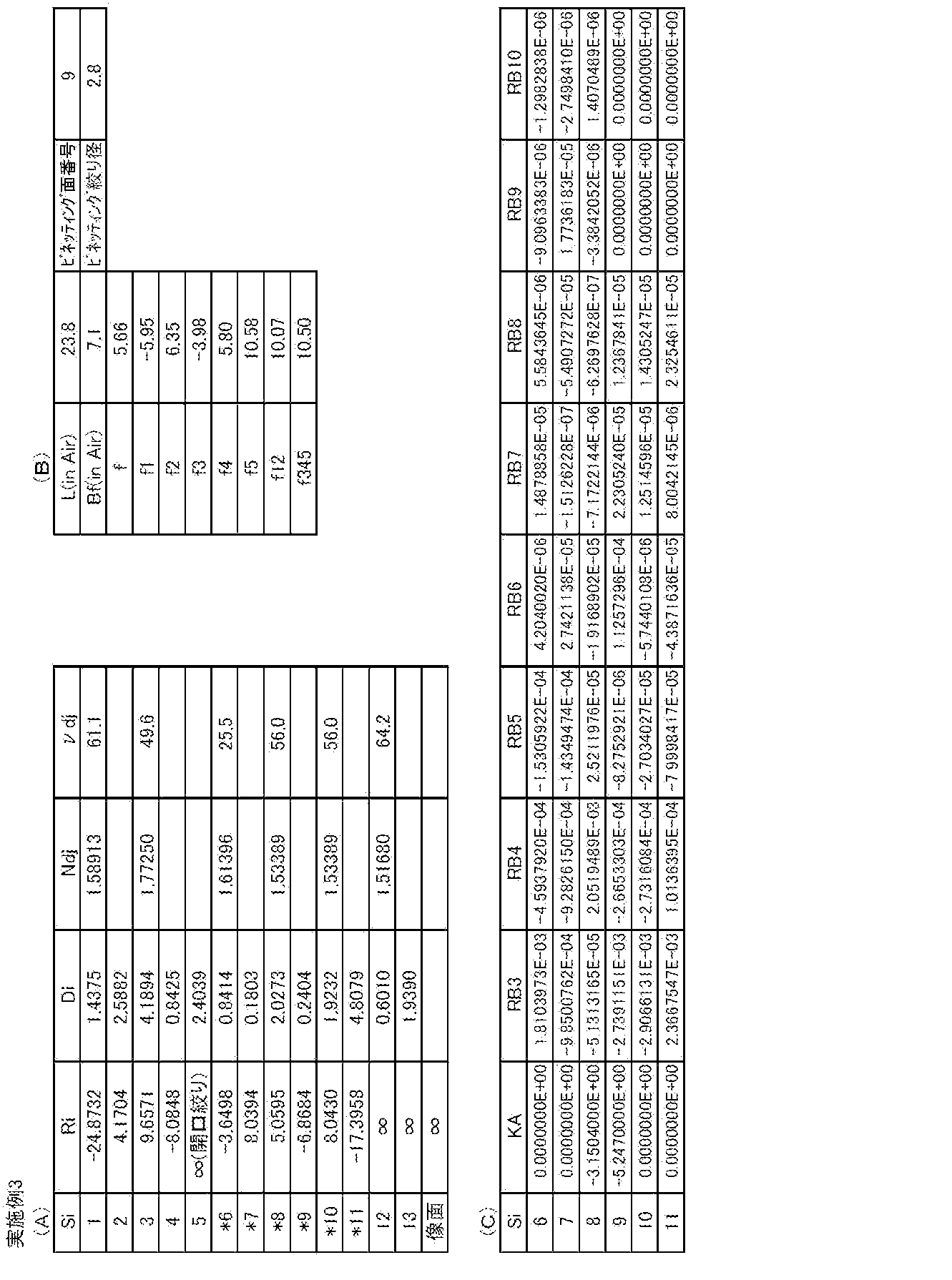


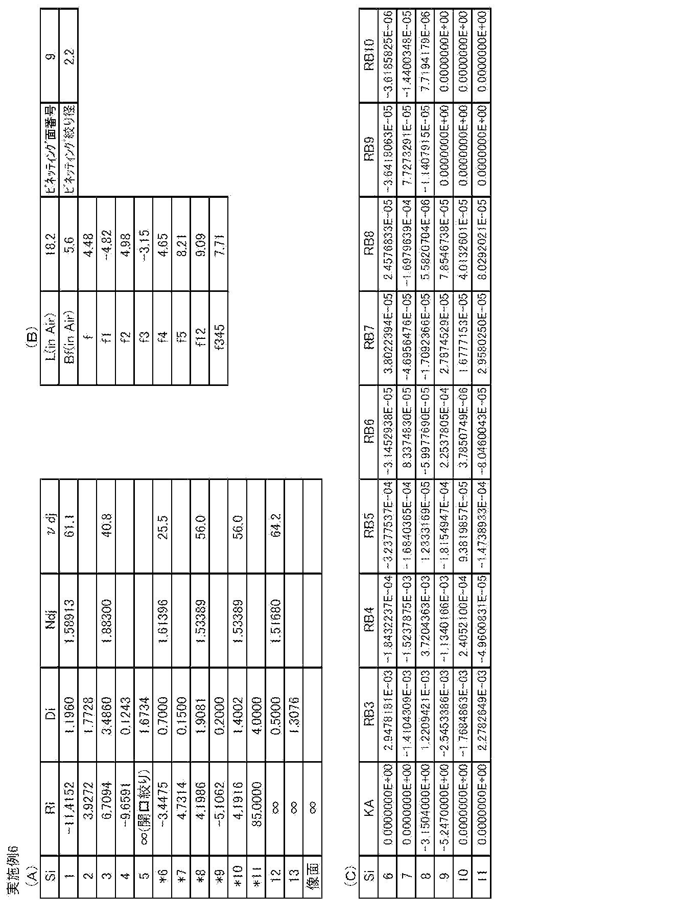


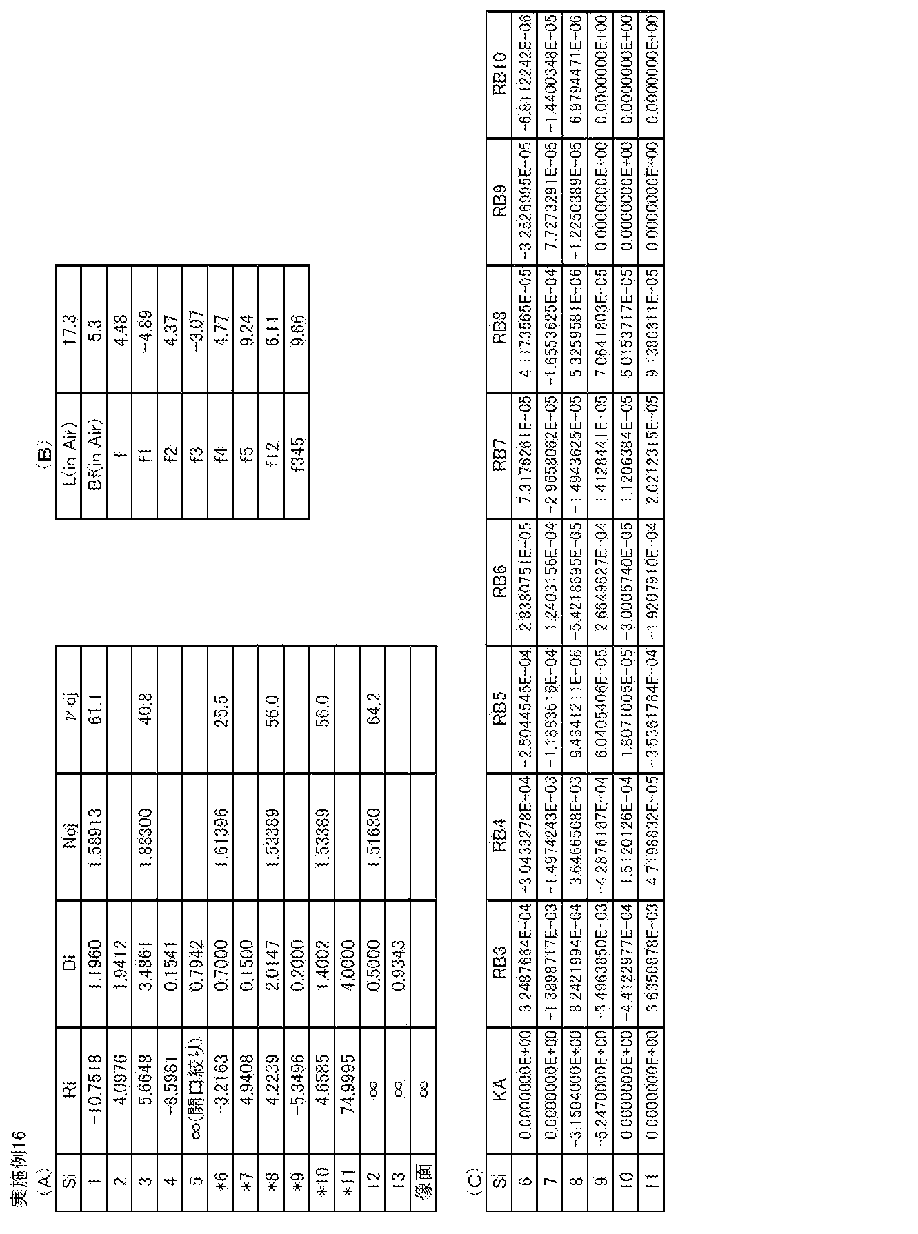


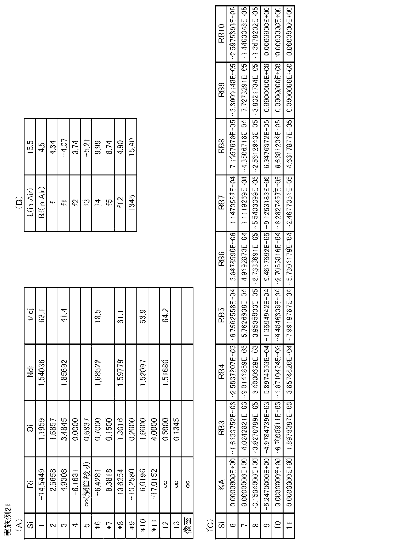


上記実施例1~23の撮像レンズでは全て、第1レンズL1、第2レンズL2はガラス球面レンズであり、第3レンズL3、第4レンズL4、第5レンズL5はプラスチック非球面レンズである。
In all the imaging lenses of Examples 1 to 23, the first lens L1 and the second lens L2 are glass spherical lenses, and the third lens L3, the fourth lens L4, and the fifth lens L5 are plastic aspheric lenses.
実施例1~23の撮像レンズにおける条件式(1)~(14)に対応する値を表24に示す。実施例1~23では、d線を基準波長としており、表24にはこの基準波長における各値を示す。
Table 24 shows values corresponding to the conditional expressions (1) to (14) in the imaging lenses of Examples 1 to 23. In Examples 1 to 23, the d-line is used as a reference wavelength, and Table 24 shows values at this reference wavelength.
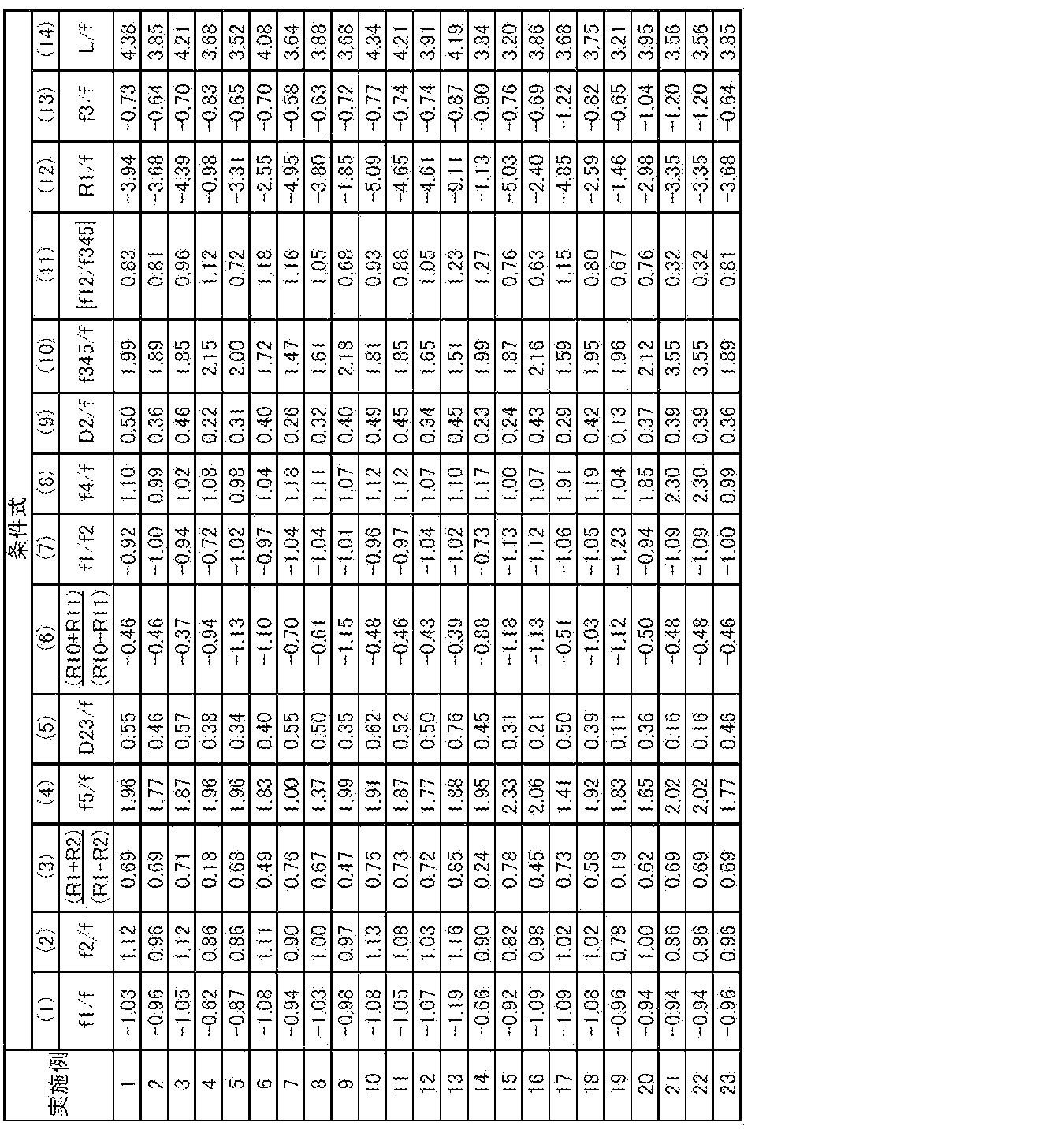
上記実施例1~23にかかる撮像レンズの各収差図をそれぞれ、図27(A)~図27(D)、図28(A)~図28(D)、図29(A)~図29(D)、図30(A)~図30(D)、図31(A)~図31(D)、図32(A)~図32(D)、図33(A)~図33(D)、図34(A)~図34(D)、図35(A)~図35(D)、図36(A)~図36(D)、図37(A)~図37(D)、図38(A)~図38(D)、図39(A)~図39(D)、図40(A)~図40(D)、図41(A)~図41(D)、図42(A)~図42(D)、図43(A)~図43(D)、図44(A)~図44(D)、図45(A)~図45(D)、図46(A)~図46(D)、図47(A)~図47(D)、図48(A)~図48(D)、図49(A)~図49(D)に示す。
The aberration diagrams of the imaging lenses according to Examples 1 to 23 are shown in FIGS. 27 (A) to 27 (D), FIGS. 28 (A) to 28 (D), and FIGS. D), FIG. 30 (A) to FIG. 30 (D), FIG. 31 (A) to FIG. 31 (D), FIG. 32 (A) to FIG. 32 (D), FIG. 33 (A) to FIG. 34 (A) to 34 (D), 35 (A) to 35 (D), 36 (A) to 36 (D), 37 (A) to 37 (D), FIG. 38 (A) to FIG. 38 (D), FIG. 39 (A) to FIG. 39 (D), FIG. 40 (A) to FIG. 40 (D), FIG. 41 (A) to FIG. 41 (D), FIG. A) to FIG. 42 (D), FIG. 43 (A) to FIG. 43 (D), FIG. 44 (A) to FIG. 44 (D), FIG. 45 (A) to FIG. 45 (D), FIG. FIG. 46 (D), FIG. 47 (A) to FIG. 47 (D), FIG. 48 (A) to FIG. (D), shown in FIG. 49 (A) ~ FIG 49 (D).
ここでは、実施例1の収差図を例にとり説明するが、他の実施例の収差図についても同様である。図27(A)、図27(B)、図27(C)、図27(D)はそれぞれ、実施例1にかかる撮像レンズの球面収差、非点収差、ディストーション(歪曲収差)、倍率色収差(倍率の色収差)の収差図を示す。球面収差図のFno.はF値を意味し、その他の収差図のωは半画角を意味する。ディストーションの図は、全系の焦点距離f、画角φ(変数扱い、0≦φ≦ω)を用いて、理想像高をf×tan(φ)とし、それからのずれ量を示す。各収差図には、d線(587.56nm)を基準波長とした収差を示すが、球面収差図には、F線(波長486.13nm)、C線(波長656.27nm)、s線(波長852.11nm)、正弦条件違反量(SNCと表記)についての収差も示し、倍率の色収差図にはF線、C線、s線についての収差を示す。倍率の色収差図の線種は球面収差図のものと同じであるため、その表記を省略している。
Here, the aberration diagrams of Example 1 will be described as an example, but the same applies to the aberration diagrams of other Examples. 27 (A), 27 (B), 27 (C), and 27 (D) are respectively spherical aberration, astigmatism, distortion (distortion aberration), and lateral chromatic aberration (for the imaging lens according to Example 1). The aberration diagram of chromatic aberration of magnification) is shown. Fno. Of spherical aberration diagram. Means F value, and ω in other aberration diagrams means half angle of view. The distortion diagram shows the amount of deviation from the ideal image height f × tan (φ) using the focal length f and angle of view φ (variable treatment, 0 ≦ φ ≦ ω) of the entire system. Each aberration diagram shows aberrations with the d-line (587.56 nm) as the reference wavelength, while the spherical aberration diagram shows the F-line (wavelength 486.13 nm), C-line (wavelength 656.27 nm), and s-line ( The aberration for the sine condition violation amount (denoted as SNC) is also shown, and the magnification chromatic aberration diagram shows the aberration for the F-line, C-line, and s-line. Since the line type of the chromatic aberration diagram of magnification is the same as that of the spherical aberration diagram, the description is omitted.
以上のデータからわかるように、実施例1~23の撮像レンズは、小型で安価に構成され、Fナンバーが1.60~2.00と小さく、全画角が45.0°~65.4°であり、十分長いバックフォーカスを有し、諸収差が良好に補正されて良好な光学性能を有する。これらの撮像レンズは、監視カメラや、自動車の前方、側方、後方などの映像を撮影するための車載用カメラ等に好適に使用可能である。
As can be seen from the above data, the imaging lenses of Examples 1 to 23 are small and inexpensive, have a small F number of 1.60 to 2.00, and a total angle of view of 45.0 ° to 65.4. It has a sufficiently long back focus, various aberrations are well corrected, and good optical performance. These imaging lenses can be suitably used for surveillance cameras, in-vehicle cameras for taking images of the front, side, rear, etc. of automobiles.
図50に使用例として、自動車100に本実施形態の撮像レンズを備えた撮像装置を搭載した様子を示す。図50において、自動車100は、その助手席側の側面の死角範囲を撮像するための車外カメラ101と、自動車100の後側の死角範囲を撮像するための車外カメラ102と、ルームミラーの背面に取り付けられ、ドライバーと同じ視野範囲を撮影するための車内カメラ103とを備えている。車外カメラ101と車外カメラ102と車内カメラ103とは、本発明の実施形態にかかる撮像装置であり、本発明の実施形態にかかる撮像レンズと、該撮像レンズにより形成される光学像を電気信号に変換する撮像素子とを備えている。
As an example of use, FIG. 50 shows a state in which an imaging apparatus including the imaging lens of the present embodiment is mounted on the automobile 100. In FIG. 50, an automobile 100 includes an on-vehicle camera 101 for imaging a blind spot range on the side surface on the passenger seat side, an on-vehicle camera 102 for imaging a blind spot range on the rear side of the automobile 100, and a rear surface of a rearview mirror. An in-vehicle camera 103 is attached and is used for photographing the same field of view as the driver. The outside camera 101, the outside camera 102, and the inside camera 103 are imaging devices according to the embodiment of the present invention. An imaging lens according to the embodiment of the present invention and an optical image formed by the imaging lens are used as electrical signals. An image sensor for conversion.
本発明の実施形態にかかる撮像レンズは、上述した長所を有するものであるから、車外カメラ101、102および車内カメラ103は、小型で安価に構成でき、低照度の撮影条件下でも使用可能であり、撮像素子を用いて解像度の高い良好な像を得ることができる。
Since the imaging lens according to the embodiment of the present invention has the above-described advantages, the outside cameras 101 and 102 and the in-vehicle camera 103 can be configured to be small and inexpensive, and can be used even under low illumination conditions. A good image with high resolution can be obtained using the image sensor.
以上、実施形態および実施例を挙げて本発明を説明したが、本発明は上記実施形態および実施例に限定されず、種々の変形が可能である。例えば、各レンズ成分の曲率半径、面間隔、屈折率、アッベ数、非球面係数の値は、上記各数値実施例で示した値に限定されず、他の値をとり得るものである。
The present invention has been described with reference to the embodiments and examples. However, the present invention is not limited to the above-described embodiments and examples, and various modifications can be made. For example, the values of the radius of curvature, the surface interval, the refractive index, the Abbe number, and the aspheric coefficient of each lens component are not limited to the values shown in the above numerical examples, and can take other values.
また、撮像装置の実施形態では、本発明を車載用カメラに適用した例について図を示して説明したが、本発明はこの用途に限定されるものではなく、例えば、携帯端末用カメラや監視カメラ等にも適用可能である。
Further, in the embodiment of the imaging apparatus, the example in which the present invention is applied to a vehicle-mounted camera has been described with reference to the drawings. However, the present invention is not limited to this application, and for example, a mobile terminal camera or a surveillance camera The present invention can also be applied.
Claims (16)
- 物体側から順に、物体側に凹面を向けた負の第1レンズと、正の第2レンズと、負の第3レンズと、物体側に凸面を向けた正の第4レンズと、正の第5レンズとを備え、
絞りが、前記第1レンズの像側の面と前記第3レンズの物体側の面の間に配置され、
全系の焦点距離をfとし、前記第1レンズの焦点距離をf1としたとき、下記条件式(1)を満足することを特徴とする撮像レンズ。
-1.25<f1/f<-0.5 … (1) In order from the object side, a negative first lens having a concave surface directed toward the object side, a positive second lens, a negative third lens, a positive fourth lens having a convex surface directed toward the object side, and a positive first lens With 5 lenses,
An aperture is disposed between the image-side surface of the first lens and the object-side surface of the third lens;
An imaging lens satisfying conditional expression (1) below, where f is a focal length of the entire system and f1 is a focal length of the first lens.
-1.25 <f1 / f <-0.5 (1) - 物体側から順に、物体側に凹面を向けた負の第1レンズと、正の第2レンズと、負の第3レンズと、物体側に凸面を向けた正の第4レンズと、正の第5レンズとを備え、
絞りが、前記第1レンズの像側の面と前記第3レンズの物体側の面の間に配置され、
全系の焦点距離をfとし、前記第2レンズの焦点距離をf2とし、前記第1レンズの物体側、像側の面の曲率半径をそれぞれR1、R2としたとき、下記条件式(2)、(3)を満足することを特徴とする撮像レンズ。
0.4<f2/f<1.5 … (2)
0.05<(R1+R2)/(R1-R2)<0.95 … (3) In order from the object side, a negative first lens having a concave surface directed toward the object side, a positive second lens, a negative third lens, a positive fourth lens having a convex surface directed toward the object side, and a positive first lens With 5 lenses,
An aperture is disposed between the image-side surface of the first lens and the object-side surface of the third lens;
When the focal length of the entire system is f, the focal length of the second lens is f2, and the curvature radii of the object-side and image-side surfaces of the first lens are R1 and R2, respectively, the following conditional expression (2) , (3) satisfies the imaging lens.
0.4 <f2 / f <1.5 (2)
0.05 <(R1 + R2) / (R1-R2) <0.95 (3) - 物体側から順に、物体側に凹面を向けた負の第1レンズと、正の第2レンズと、負の第3レンズと、物体側に凸面を向けた正の第4レンズと、正の第5レンズとを備え、
絞りが、前記第1レンズの像側の面と前記第3レンズの物体側の面の間に配置され、
全系の焦点距離をfとし、前記第5レンズの焦点距離をf5としたとき、下記条件式(4)を満足することを特徴とする撮像レンズ。
0.99<f5/f<2.10 … (4) In order from the object side, a negative first lens having a concave surface directed toward the object side, a positive second lens, a negative third lens, a positive fourth lens having a convex surface directed toward the object side, and a positive first lens With 5 lenses,
An aperture is disposed between the image-side surface of the first lens and the object-side surface of the third lens;
An imaging lens satisfying conditional expression (4) below, where f is a focal length of the entire system and f5 is a focal length of the fifth lens.
0.99 <f5 / f <2.10 (4) - 全系の焦点距離をfとし、前記第2レンズと前記第3レンズとの光軸上の間隔をD23としたとき、下記条件式(5)を満足することを特徴とする請求項1から3のいずれか一項記載の撮像レンズ。
0.05<D23/f<0.85 … (5) The following conditional expression (5) is satisfied, where f is the focal length of the entire system and D23 is the distance on the optical axis between the second lens and the third lens. The imaging lens according to claim 1.
0.05 <D23 / f <0.85 (5) - 前記第1レンズが両凹レンズであることを特徴とする請求項1から4のいずれか一項記載の撮像レンズ。 The imaging lens according to any one of claims 1 to 4, wherein the first lens is a biconcave lens.
- 前記第5レンズの物体側、像側の面の曲率半径をそれぞれR10、R11としたとき、下記条件式(6)を満足することを特徴とする請求項1から5のいずれか一項記載の撮像レンズ。
-1.40<(R10+R11)/(R10-R11)<-0.2 … (6) The following conditional expression (6) is satisfied, where the curvature radii of the object side surface and the image side surface of the fifth lens are R10 and R11, respectively. Imaging lens.
−1.40 <(R10 + R11) / (R10−R11) <− 0.2 (6) - 前記第1レンズの焦点距離をf1とし、前記第2レンズの焦点距離をf2としたとき、下記条件式(7)を満足することを特徴とする請求項1から6のいずれか一項記載の撮像レンズ。
-1.30<f1/f2<-0.65 … (7) The following conditional expression (7) is satisfied, where f1 is a focal length of the first lens and f2 is a focal length of the second lens. Imaging lens.
−1.30 <f1 / f2 <−0.65 (7) - 前記第3レンズの物体側の面は、中心が負のパワーを持ち、軸上光線径端では中心と比べて負のパワーが弱いことを特徴とする請求項1から7のいずれか一項記載の撮像レンズ。 The object side surface of the third lens has a negative power at the center, and a negative power is weaker at the end of the axial ray diameter than at the center. Imaging lens.
- 前記第3レンズの像側の面は、中心が負のパワーを持ち、軸上光線径端では中心と比べて負のパワーが弱いか、もしくは、中心が負のパワーを持ち、軸上光線径端で正のパワーを持つことを特徴とする請求項1から8のいずれか一項記載の撮像レンズ。 The image-side surface of the third lens has a negative power at the center, and the negative power is weaker than the center at the end of the axial beam diameter, or the center has a negative power and the axial beam diameter. The imaging lens according to claim 1, wherein the imaging lens has positive power at an end.
- 前記第4レンズの像側の面は、中心が正のパワーを持ち、軸上光線径端では中心と比べて正のパワーが弱いか、もしくは、中心が正のパワーを持ち、軸上光線径端では負のパワーを持つことを特徴とする請求項1から9のいずれか一項記載の撮像レンズ。 The image-side surface of the fourth lens has a positive power at the center and is weaker at the axial beam diameter end than the center, or has a positive power at the center and has an axial beam diameter. The imaging lens according to claim 1, wherein the imaging lens has negative power at the end.
- 前記第5レンズの像側の面は、中心が正のパワーを持ち、軸上光線径端では中心と比べて正のパワーが弱いか、もしくは、中心が正のパワーを持ち、軸上光線径端では負のパワーを持つことを特徴とする請求項1から10のいずれか一項記載の撮像レンズ。 The image-side surface of the fifth lens has a positive power at the center, and the positive power is weaker than the center at the end of the axial ray diameter, or the center has a positive power and the axial ray diameter. The imaging lens according to claim 1, wherein the imaging lens has negative power at an end.
- 全系の焦点距離をfとし、前記第1レンズの焦点距離をf1としたとき、下記条件式(1-3)を満足することを特徴とする請求項1から11のいずれか一項記載の撮像レンズ。
-1.10<f1/f<-0.60 … (1-3) The conditional expression (1-3) below is satisfied, where f is a focal length of the entire system and f1 is a focal length of the first lens. Imaging lens.
−1.10 <f1 / f <−0.60 (1-3) - 全系の焦点距離をfとし、前記第2レンズの焦点距離をf2としたとき、下記条件式(2-1)を満足することを特徴とする請求項1から12のいずれか一項記載の撮像レンズ。
0.7<f2/f<1.2 … (2-1) The conditional expression (2-1) below is satisfied, where f is a focal length of the entire system and f2 is a focal length of the second lens. Imaging lens.
0.7 <f2 / f <1.2 (2-1) - 前記第1レンズの物体側、像側の面の曲率半径をそれぞれR1、R2としたとき、下記条件式(3-1)を満足することを特徴とする請求項1から13のいずれか一項記載の撮像レンズ。
0.6<(R1+R2)/(R1-R2)<0.90 … (3-1) The conditional expression (3-1) below is satisfied, where R1 and R2 are the curvature radii of the object side surface and the image side surface of the first lens, respectively. The imaging lens described.
0.6 <(R1 + R2) / (R1-R2) <0.90 (3-1) - 全系の焦点距離をfとし、前記第5レンズの焦点距離をf5としたとき、下記条件式(4-1)を満足することを特徴とする請求項1から14のいずれか一項記載の撮像レンズ。
1.30<f5/f<2.05 … (4-1) The following conditional expression (4-1) is satisfied, where f is a focal length of the entire system and f5 is a focal length of the fifth lens. Imaging lens.
1.30 <f5 / f <2.05 (4-1) - 請求項1から15のいずれか一項記載の撮像レンズを備えたことを特徴とする撮像装置。 An imaging apparatus comprising the imaging lens according to any one of claims 1 to 15.
Priority Applications (4)
| Application Number | Priority Date | Filing Date | Title |
|---|---|---|---|
| CN201180061922.8A CN103492924B (en) | 2010-12-21 | 2011-12-20 | Imaging lens and imaging device |
| EP11850589.0A EP2657742B1 (en) | 2010-12-21 | 2011-12-20 | Imaging lens and imaging device |
| JP2012549638A JP5657696B2 (en) | 2010-12-21 | 2011-12-20 | Imaging lens and imaging apparatus |
| US13/907,003 US8670192B2 (en) | 2010-12-21 | 2013-05-31 | Imaging lens and imaging apparatus |
Applications Claiming Priority (2)
| Application Number | Priority Date | Filing Date | Title |
|---|---|---|---|
| JP2010-284363 | 2010-12-21 | ||
| JP2010284363 | 2010-12-21 |
Related Child Applications (1)
| Application Number | Title | Priority Date | Filing Date |
|---|---|---|---|
| US13/907,003 Continuation US8670192B2 (en) | 2010-12-21 | 2013-05-31 | Imaging lens and imaging apparatus |
Publications (1)
| Publication Number | Publication Date |
|---|---|
| WO2012086193A1 true WO2012086193A1 (en) | 2012-06-28 |
Family
ID=46313484
Family Applications (1)
| Application Number | Title | Priority Date | Filing Date |
|---|---|---|---|
| PCT/JP2011/007141 WO2012086193A1 (en) | 2010-12-21 | 2011-12-20 | Imaging lens and imaging device |
Country Status (5)
| Country | Link |
|---|---|
| US (1) | US8670192B2 (en) |
| EP (1) | EP2657742B1 (en) |
| JP (1) | JP5657696B2 (en) |
| CN (1) | CN103492924B (en) |
| WO (1) | WO2012086193A1 (en) |
Cited By (3)
| Publication number | Priority date | Publication date | Assignee | Title |
|---|---|---|---|---|
| CN105074529A (en) * | 2013-02-28 | 2015-11-18 | 富士胶片株式会社 | Imaging lens and imaging device |
| JP2017116795A (en) * | 2015-12-25 | 2017-06-29 | 株式会社タムロン | Image capturing lens and image capturing device |
| JP2019174848A (en) * | 2019-07-11 | 2019-10-10 | 株式会社タムロン | Image capturing lens and image capturing device |
Families Citing this family (14)
| Publication number | Priority date | Publication date | Assignee | Title |
|---|---|---|---|---|
| TWI461731B (en) * | 2012-05-18 | 2014-11-21 | Largan Precision Co Ltd | Image lens system |
| TWI565969B (en) * | 2012-11-26 | 2017-01-11 | 鴻海精密工業股份有限公司 | Wide-angle image lens |
| TWI485425B (en) | 2014-05-26 | 2015-05-21 | Largan Precision Co Ltd | Imaging optical system, image capturing device and mobile terminal |
| CN105892046B (en) * | 2016-03-24 | 2018-08-31 | 武汉华工激光工程有限责任公司 | Infrared two-dimensional scan microscope group |
| TWI591376B (en) * | 2016-05-09 | 2017-07-11 | 大立光電股份有限公司 | Imaging lens assembly and electronic device |
| CN107436474B (en) * | 2016-05-26 | 2021-04-16 | 信泰光学(深圳)有限公司 | Projection lens |
| EP3343894B1 (en) * | 2016-12-28 | 2018-10-31 | Axis AB | Ir-filter arrangement |
| TWI639037B (en) * | 2017-01-04 | 2018-10-21 | 先進光電科技股份有限公司 | Optical image capturing system |
| CN108508572B (en) * | 2017-02-28 | 2020-10-30 | 宁波舜宇车载光学技术有限公司 | Optical lens |
| US10564398B2 (en) | 2017-12-27 | 2020-02-18 | Rays Optics Inc. | Lens and manufacturing method thereof |
| CN111830673A (en) * | 2019-04-23 | 2020-10-27 | 宁波舜宇车载光学技术有限公司 | Optical lens and imaging apparatus |
| WO2021189457A1 (en) * | 2020-03-27 | 2021-09-30 | 天津欧菲光电有限公司 | Lens system, image capturing module, electronic device and driving device |
| DE102020115494B3 (en) | 2020-05-19 | 2021-04-22 | Jenoptik Optical Systems Gmbh | Lens, use of a lens, measuring system with a lens and use of a biaspheric plastic lens in a lens |
| CN113064261B (en) * | 2021-05-10 | 2023-05-26 | 协益电子(苏州)有限公司 | Monitoring lens for vehicle |
Citations (15)
| Publication number | Priority date | Publication date | Assignee | Title |
|---|---|---|---|---|
| JPS6370817A (en) * | 1986-09-12 | 1988-03-31 | Matsushita Electric Ind Co Ltd | Single focus lens |
| JPH0545582A (en) * | 1990-07-06 | 1993-02-23 | Asahi Optical Co Ltd | Magnifying projection lens |
| JPH10213742A (en) | 1997-01-30 | 1998-08-11 | Asahi Optical Co Ltd | Photographic lens system |
| JPH1184230A (en) * | 1997-09-08 | 1999-03-26 | Copal Co Ltd | Compact wide-angle lens |
| JPH11142730A (en) | 1997-09-04 | 1999-05-28 | Konica Corp | Image pickup lens |
| JP2000066091A (en) | 1998-08-18 | 2000-03-03 | Nikon Corp | Image pickup lens |
| JP2002072095A (en) * | 2000-09-01 | 2002-03-12 | Minolta Co Ltd | Imaging device |
| JP2003066328A (en) | 2001-08-24 | 2003-03-05 | Canon Inc | Lens system and optical equipment having the same |
| JP2003131126A (en) * | 2001-10-29 | 2003-05-08 | Nidec Copal Corp | Wide angle lens |
| JP2004069778A (en) * | 2002-08-01 | 2004-03-04 | Sony Corp | Photographic lens |
| JP2008008960A (en) | 2006-06-27 | 2008-01-17 | Kyocera Corp | Lens unit |
| JP2009210596A (en) * | 2008-02-29 | 2009-09-17 | Fujinon Corp | Projection lens and projection type display apparatus using the same |
| JP2009230041A (en) * | 2008-03-25 | 2009-10-08 | Brother Ind Ltd | Wide-angle imaging lens |
| JP2010107606A (en) | 2008-10-29 | 2010-05-13 | Fujinon Corp | Imaging lens and imaging apparatus |
| JP2010197599A (en) * | 2009-02-24 | 2010-09-09 | Fujifilm Corp | Projection lens and projection type display device using the same |
Family Cites Families (3)
| Publication number | Priority date | Publication date | Assignee | Title |
|---|---|---|---|---|
| US5278698A (en) * | 1990-07-06 | 1994-01-11 | Asahi Kogaku Kogyo Kabushiki Kaisha | Magnifying projecting lens |
| TW484019B (en) * | 1998-12-11 | 2002-04-21 | Minolta Co Ltd | A taking lens system |
| JP5585122B2 (en) * | 2010-02-25 | 2014-09-10 | 株式会社リコー | Imaging lens, twin stereo camera and distance measuring device |
-
2011
- 2011-12-20 CN CN201180061922.8A patent/CN103492924B/en active Active
- 2011-12-20 WO PCT/JP2011/007141 patent/WO2012086193A1/en active Application Filing
- 2011-12-20 JP JP2012549638A patent/JP5657696B2/en not_active Expired - Fee Related
- 2011-12-20 EP EP11850589.0A patent/EP2657742B1/en not_active Not-in-force
-
2013
- 2013-05-31 US US13/907,003 patent/US8670192B2/en active Active
Patent Citations (15)
| Publication number | Priority date | Publication date | Assignee | Title |
|---|---|---|---|---|
| JPS6370817A (en) * | 1986-09-12 | 1988-03-31 | Matsushita Electric Ind Co Ltd | Single focus lens |
| JPH0545582A (en) * | 1990-07-06 | 1993-02-23 | Asahi Optical Co Ltd | Magnifying projection lens |
| JPH10213742A (en) | 1997-01-30 | 1998-08-11 | Asahi Optical Co Ltd | Photographic lens system |
| JPH11142730A (en) | 1997-09-04 | 1999-05-28 | Konica Corp | Image pickup lens |
| JPH1184230A (en) * | 1997-09-08 | 1999-03-26 | Copal Co Ltd | Compact wide-angle lens |
| JP2000066091A (en) | 1998-08-18 | 2000-03-03 | Nikon Corp | Image pickup lens |
| JP2002072095A (en) * | 2000-09-01 | 2002-03-12 | Minolta Co Ltd | Imaging device |
| JP2003066328A (en) | 2001-08-24 | 2003-03-05 | Canon Inc | Lens system and optical equipment having the same |
| JP2003131126A (en) * | 2001-10-29 | 2003-05-08 | Nidec Copal Corp | Wide angle lens |
| JP2004069778A (en) * | 2002-08-01 | 2004-03-04 | Sony Corp | Photographic lens |
| JP2008008960A (en) | 2006-06-27 | 2008-01-17 | Kyocera Corp | Lens unit |
| JP2009210596A (en) * | 2008-02-29 | 2009-09-17 | Fujinon Corp | Projection lens and projection type display apparatus using the same |
| JP2009230041A (en) * | 2008-03-25 | 2009-10-08 | Brother Ind Ltd | Wide-angle imaging lens |
| JP2010107606A (en) | 2008-10-29 | 2010-05-13 | Fujinon Corp | Imaging lens and imaging apparatus |
| JP2010197599A (en) * | 2009-02-24 | 2010-09-09 | Fujifilm Corp | Projection lens and projection type display device using the same |
Cited By (4)
| Publication number | Priority date | Publication date | Assignee | Title |
|---|---|---|---|---|
| CN105074529A (en) * | 2013-02-28 | 2015-11-18 | 富士胶片株式会社 | Imaging lens and imaging device |
| US9753248B2 (en) | 2013-02-28 | 2017-09-05 | Fujifilm Corporation | Imaging lens and imaging apparatus |
| JP2017116795A (en) * | 2015-12-25 | 2017-06-29 | 株式会社タムロン | Image capturing lens and image capturing device |
| JP2019174848A (en) * | 2019-07-11 | 2019-10-10 | 株式会社タムロン | Image capturing lens and image capturing device |
Also Published As
| Publication number | Publication date |
|---|---|
| EP2657742B1 (en) | 2018-10-24 |
| EP2657742A1 (en) | 2013-10-30 |
| CN103492924B (en) | 2016-01-06 |
| CN103492924A (en) | 2014-01-01 |
| EP2657742A4 (en) | 2017-01-04 |
| US20130258492A1 (en) | 2013-10-03 |
| JP5657696B2 (en) | 2015-01-21 |
| JPWO2012086193A1 (en) | 2014-05-22 |
| US8670192B2 (en) | 2014-03-11 |
Similar Documents
| Publication | Publication Date | Title |
|---|---|---|
| JP5657696B2 (en) | Imaging lens and imaging apparatus | |
| WO2012086199A1 (en) | Image pickup lens and image pickup device | |
| JP5330202B2 (en) | Imaging lens and imaging apparatus | |
| JP5576717B2 (en) | Imaging lens and imaging apparatus | |
| JP5847829B2 (en) | Imaging lens and imaging apparatus | |
| JP6145887B2 (en) | Imaging lens and imaging apparatus | |
| JP5270425B2 (en) | Imaging lens and imaging apparatus | |
| JP6066424B2 (en) | Imaging lens and imaging apparatus | |
| JP2015194787A (en) | Image capturing lens and image capturing device | |
| JP2011215443A (en) | Image pickup lens and image pickup apparatus | |
| JP2011257462A (en) | Imaging lens and imaging device | |
| JP2013073156A (en) | Image pickup lens and image pickup apparatus | |
| WO2012066750A1 (en) | Image pickup lens and image pickup device | |
| JP5568732B2 (en) | Imaging lens | |
| JP5657697B2 (en) | Imaging lens and imaging apparatus | |
| JP6145888B2 (en) | Imaging lens and imaging apparatus | |
| JP5486408B2 (en) | Imaging lens and imaging apparatus | |
| JP2013073157A (en) | Image pickup lens and image pickup apparatus | |
| JP2013073155A (en) | Image pickup lens and image pickup apparatus | |
| JP5629250B2 (en) | Imaging lens and imaging apparatus | |
| JP5633937B2 (en) | Imaging lens and imaging apparatus | |
| JP2013073152A (en) | Image pickup lens and image pickup apparatus | |
| JP5638495B2 (en) | Imaging lens and imaging apparatus | |
| JP2013073151A (en) | Image pickup lens and image pickup apparatus | |
| JP2013073166A (en) | Image pickup lens and image pickup apparatus |
Legal Events
| Date | Code | Title | Description |
|---|---|---|---|
| 121 | Ep: the epo has been informed by wipo that ep was designated in this application |
Ref document number: 11850589 Country of ref document: EP Kind code of ref document: A1 |
|
| DPE2 | Request for preliminary examination filed before expiration of 19th month from priority date (pct application filed from 20040101) | ||
| ENP | Entry into the national phase |
Ref document number: 2012549638 Country of ref document: JP Kind code of ref document: A |
|
| NENP | Non-entry into the national phase |
Ref country code: DE |
|
| WWE | Wipo information: entry into national phase |
Ref document number: 2011850589 Country of ref document: EP |