WO2012084486A1 - A cooling device comprising a condenser cooled by a fan - Google Patents
A cooling device comprising a condenser cooled by a fan Download PDFInfo
- Publication number
- WO2012084486A1 WO2012084486A1 PCT/EP2011/071865 EP2011071865W WO2012084486A1 WO 2012084486 A1 WO2012084486 A1 WO 2012084486A1 EP 2011071865 W EP2011071865 W EP 2011071865W WO 2012084486 A1 WO2012084486 A1 WO 2012084486A1
- Authority
- WO
- WIPO (PCT)
- Prior art keywords
- fan
- condenser
- refrigerant tube
- cooling device
- refrigerant
- Prior art date
- Legal status (The legal status is an assumption and is not a legal conclusion. Google has not performed a legal analysis and makes no representation as to the accuracy of the status listed.)
- Ceased
Links
Images

Classifications
-
- F—MECHANICAL ENGINEERING; LIGHTING; HEATING; WEAPONS; BLASTING
- F25—REFRIGERATION OR COOLING; COMBINED HEATING AND REFRIGERATION SYSTEMS; HEAT PUMP SYSTEMS; MANUFACTURE OR STORAGE OF ICE; LIQUEFACTION SOLIDIFICATION OF GASES
- F25B—REFRIGERATION MACHINES, PLANTS OR SYSTEMS; COMBINED HEATING AND REFRIGERATION SYSTEMS; HEAT PUMP SYSTEMS
- F25B39/00—Evaporators; Condensers
- F25B39/04—Condensers
-
- F—MECHANICAL ENGINEERING; LIGHTING; HEATING; WEAPONS; BLASTING
- F25—REFRIGERATION OR COOLING; COMBINED HEATING AND REFRIGERATION SYSTEMS; HEAT PUMP SYSTEMS; MANUFACTURE OR STORAGE OF ICE; LIQUEFACTION SOLIDIFICATION OF GASES
- F25D—REFRIGERATORS; COLD ROOMS; ICE-BOXES; COOLING OR FREEZING APPARATUS NOT OTHERWISE PROVIDED FOR
- F25D23/00—General constructional features
- F25D23/003—General constructional features for cooling refrigerating machinery
-
- F—MECHANICAL ENGINEERING; LIGHTING; HEATING; WEAPONS; BLASTING
- F28—HEAT EXCHANGE IN GENERAL
- F28D—HEAT-EXCHANGE APPARATUS, NOT PROVIDED FOR IN ANOTHER SUBCLASS, IN WHICH THE HEAT-EXCHANGE MEDIA DO NOT COME INTO DIRECT CONTACT
- F28D1/00—Heat-exchange apparatus having stationary conduit assemblies for one heat-exchange medium only, the media being in contact with different sides of the conduit wall, in which the other heat-exchange medium is a large body of fluid, e.g. domestic or motor car radiators
- F28D1/02—Heat-exchange apparatus having stationary conduit assemblies for one heat-exchange medium only, the media being in contact with different sides of the conduit wall, in which the other heat-exchange medium is a large body of fluid, e.g. domestic or motor car radiators with heat-exchange conduits immersed in the body of fluid
- F28D1/04—Heat-exchange apparatus having stationary conduit assemblies for one heat-exchange medium only, the media being in contact with different sides of the conduit wall, in which the other heat-exchange medium is a large body of fluid, e.g. domestic or motor car radiators with heat-exchange conduits immersed in the body of fluid with tubular conduits
- F28D1/0408—Multi-circuit heat exchangers, e.g. integrating different heat exchange sections in the same unit or heat exchangers for more than two fluids
-
- F—MECHANICAL ENGINEERING; LIGHTING; HEATING; WEAPONS; BLASTING
- F28—HEAT EXCHANGE IN GENERAL
- F28D—HEAT-EXCHANGE APPARATUS, NOT PROVIDED FOR IN ANOTHER SUBCLASS, IN WHICH THE HEAT-EXCHANGE MEDIA DO NOT COME INTO DIRECT CONTACT
- F28D1/00—Heat-exchange apparatus having stationary conduit assemblies for one heat-exchange medium only, the media being in contact with different sides of the conduit wall, in which the other heat-exchange medium is a large body of fluid, e.g. domestic or motor car radiators
- F28D1/02—Heat-exchange apparatus having stationary conduit assemblies for one heat-exchange medium only, the media being in contact with different sides of the conduit wall, in which the other heat-exchange medium is a large body of fluid, e.g. domestic or motor car radiators with heat-exchange conduits immersed in the body of fluid
- F28D1/04—Heat-exchange apparatus having stationary conduit assemblies for one heat-exchange medium only, the media being in contact with different sides of the conduit wall, in which the other heat-exchange medium is a large body of fluid, e.g. domestic or motor car radiators with heat-exchange conduits immersed in the body of fluid with tubular conduits
- F28D1/047—Heat-exchange apparatus having stationary conduit assemblies for one heat-exchange medium only, the media being in contact with different sides of the conduit wall, in which the other heat-exchange medium is a large body of fluid, e.g. domestic or motor car radiators with heat-exchange conduits immersed in the body of fluid with tubular conduits the conduits being bent, e.g. in a serpentine or zig-zag
- F28D1/0472—Heat-exchange apparatus having stationary conduit assemblies for one heat-exchange medium only, the media being in contact with different sides of the conduit wall, in which the other heat-exchange medium is a large body of fluid, e.g. domestic or motor car radiators with heat-exchange conduits immersed in the body of fluid with tubular conduits the conduits being bent, e.g. in a serpentine or zig-zag the conduits being helically or spirally coiled
-
- F—MECHANICAL ENGINEERING; LIGHTING; HEATING; WEAPONS; BLASTING
- F28—HEAT EXCHANGE IN GENERAL
- F28D—HEAT-EXCHANGE APPARATUS, NOT PROVIDED FOR IN ANOTHER SUBCLASS, IN WHICH THE HEAT-EXCHANGE MEDIA DO NOT COME INTO DIRECT CONTACT
- F28D1/00—Heat-exchange apparatus having stationary conduit assemblies for one heat-exchange medium only, the media being in contact with different sides of the conduit wall, in which the other heat-exchange medium is a large body of fluid, e.g. domestic or motor car radiators
- F28D1/02—Heat-exchange apparatus having stationary conduit assemblies for one heat-exchange medium only, the media being in contact with different sides of the conduit wall, in which the other heat-exchange medium is a large body of fluid, e.g. domestic or motor car radiators with heat-exchange conduits immersed in the body of fluid
- F28D1/04—Heat-exchange apparatus having stationary conduit assemblies for one heat-exchange medium only, the media being in contact with different sides of the conduit wall, in which the other heat-exchange medium is a large body of fluid, e.g. domestic or motor car radiators with heat-exchange conduits immersed in the body of fluid with tubular conduits
- F28D1/047—Heat-exchange apparatus having stationary conduit assemblies for one heat-exchange medium only, the media being in contact with different sides of the conduit wall, in which the other heat-exchange medium is a large body of fluid, e.g. domestic or motor car radiators with heat-exchange conduits immersed in the body of fluid with tubular conduits the conduits being bent, e.g. in a serpentine or zig-zag
- F28D1/0477—Heat-exchange apparatus having stationary conduit assemblies for one heat-exchange medium only, the media being in contact with different sides of the conduit wall, in which the other heat-exchange medium is a large body of fluid, e.g. domestic or motor car radiators with heat-exchange conduits immersed in the body of fluid with tubular conduits the conduits being bent, e.g. in a serpentine or zig-zag the conduits being bent in a serpentine or zig-zag
-
- F—MECHANICAL ENGINEERING; LIGHTING; HEATING; WEAPONS; BLASTING
- F28—HEAT EXCHANGE IN GENERAL
- F28D—HEAT-EXCHANGE APPARATUS, NOT PROVIDED FOR IN ANOTHER SUBCLASS, IN WHICH THE HEAT-EXCHANGE MEDIA DO NOT COME INTO DIRECT CONTACT
- F28D1/00—Heat-exchange apparatus having stationary conduit assemblies for one heat-exchange medium only, the media being in contact with different sides of the conduit wall, in which the other heat-exchange medium is a large body of fluid, e.g. domestic or motor car radiators
- F28D1/02—Heat-exchange apparatus having stationary conduit assemblies for one heat-exchange medium only, the media being in contact with different sides of the conduit wall, in which the other heat-exchange medium is a large body of fluid, e.g. domestic or motor car radiators with heat-exchange conduits immersed in the body of fluid
- F28D1/04—Heat-exchange apparatus having stationary conduit assemblies for one heat-exchange medium only, the media being in contact with different sides of the conduit wall, in which the other heat-exchange medium is a large body of fluid, e.g. domestic or motor car radiators with heat-exchange conduits immersed in the body of fluid with tubular conduits
- F28D1/0408—Multi-circuit heat exchangers, e.g. integrating different heat exchange sections in the same unit or heat exchangers for more than two fluids
- F28D1/0417—Multi-circuit heat exchangers, e.g. integrating different heat exchange sections in the same unit or heat exchangers for more than two fluids with particular circuits for the same heat exchange medium, e.g. with the heat exchange medium flowing through sections having different heat exchange capacities or for heating/cooling the heat exchange medium at different temperatures
-
- F—MECHANICAL ENGINEERING; LIGHTING; HEATING; WEAPONS; BLASTING
- F28—HEAT EXCHANGE IN GENERAL
- F28D—HEAT-EXCHANGE APPARATUS, NOT PROVIDED FOR IN ANOTHER SUBCLASS, IN WHICH THE HEAT-EXCHANGE MEDIA DO NOT COME INTO DIRECT CONTACT
- F28D1/00—Heat-exchange apparatus having stationary conduit assemblies for one heat-exchange medium only, the media being in contact with different sides of the conduit wall, in which the other heat-exchange medium is a large body of fluid, e.g. domestic or motor car radiators
- F28D1/02—Heat-exchange apparatus having stationary conduit assemblies for one heat-exchange medium only, the media being in contact with different sides of the conduit wall, in which the other heat-exchange medium is a large body of fluid, e.g. domestic or motor car radiators with heat-exchange conduits immersed in the body of fluid
- F28D1/04—Heat-exchange apparatus having stationary conduit assemblies for one heat-exchange medium only, the media being in contact with different sides of the conduit wall, in which the other heat-exchange medium is a large body of fluid, e.g. domestic or motor car radiators with heat-exchange conduits immersed in the body of fluid with tubular conduits
- F28D1/0408—Multi-circuit heat exchangers, e.g. integrating different heat exchange sections in the same unit or heat exchangers for more than two fluids
- F28D1/0426—Multi-circuit heat exchangers, e.g. integrating different heat exchange sections in the same unit or heat exchangers for more than two fluids with units having particular arrangement relative to the large body of fluid, e.g. with interleaved units or with adjacent heat exchange units in common air flow or with units extending at an angle to each other or with units arranged around a central element
- F28D1/0435—Combination of units extending one behind the other
-
- F—MECHANICAL ENGINEERING; LIGHTING; HEATING; WEAPONS; BLASTING
- F28—HEAT EXCHANGE IN GENERAL
- F28D—HEAT-EXCHANGE APPARATUS, NOT PROVIDED FOR IN ANOTHER SUBCLASS, IN WHICH THE HEAT-EXCHANGE MEDIA DO NOT COME INTO DIRECT CONTACT
- F28D1/00—Heat-exchange apparatus having stationary conduit assemblies for one heat-exchange medium only, the media being in contact with different sides of the conduit wall, in which the other heat-exchange medium is a large body of fluid, e.g. domestic or motor car radiators
- F28D1/02—Heat-exchange apparatus having stationary conduit assemblies for one heat-exchange medium only, the media being in contact with different sides of the conduit wall, in which the other heat-exchange medium is a large body of fluid, e.g. domestic or motor car radiators with heat-exchange conduits immersed in the body of fluid
- F28D1/04—Heat-exchange apparatus having stationary conduit assemblies for one heat-exchange medium only, the media being in contact with different sides of the conduit wall, in which the other heat-exchange medium is a large body of fluid, e.g. domestic or motor car radiators with heat-exchange conduits immersed in the body of fluid with tubular conduits
- F28D1/0408—Multi-circuit heat exchangers, e.g. integrating different heat exchange sections in the same unit or heat exchangers for more than two fluids
- F28D1/0461—Combination of different types of heat exchanger, e.g. radiator combined with tube-and-shell heat exchanger; Arrangement of conduits for heat exchange between at least two media and for heat exchange between at least one medium and the large body of fluid
Definitions
- the present invention relates to a cooling device wherein the compressor and the condenser operating in the machine room are cooled by the fan.
- the heat absorbed from the interior of the cooling device is discharged to the outer environment by means of the condenser.
- the static type condenser that operates according to the natural heat convection principle is preferred and in no-frost refrigerators, the coil type condenser that operates according to the forced heat convection principle is preferred.
- the compressor and the condenser In no-frost refrigerators, the compressor and the condenser generally operate in the machine room which is called the cabinet base region and which is situated at the bottom portion of the refrigerator body.
- the condenser and the compressor are provided to be cooled by means of a fan situated in the machine room.
- the fan is generally of axial type and an air guide is disposed around the fan in order to guide the air blown in the axial direction by the fan directly to the condenser.
- the air guide occupies space in the machine room and due to the turbulences that occur in the air flow, the condenser and the compressor cannot be cooled efficiently.
- the elements operating in the machine room, especially the fan that rotates at high speed are required to be protected by being closed all around due to safety reasons.
- the fan operates in a casing or the machine room is closed by a lid. The elements such as the fan casing and the machine room lid slow down the air flow and an effective cooling cannot be provided in the condenser and the compressor.
- the fan disposed between the compressor and the coil shaped condenser directs the ambient air onto the compressor by sucking it from over the condenser.
- a partition is disposed between the condenser and the fan and an air guide disposed around the fan is placed in the opening situated on the partition.
- the aim of the present invention is the realization of a cooling device comprising a condenser which is provided to be efficiently cooled by the air blown by the fan.
- the cooling device realized in order to attain the aim of the present invention, explicated in the first claim and the respective claims thereof, comprises a machine room wherein the compressor and the condenser operate, and the compressor and the condenser are provided to be cooled by means of an axial fan.
- the condenser comprises two portions with different geometries.
- the refrigerant flow tube which passes through the first portion is in serpentine form and the air blown by the fan in the axial direction acts thereon.
- the second portion of the condenser has a helical flow tube which is joined with the flow tube extended from the first portion, and the helical flow tube surrounds the fan along the depth of the fan. The air blown by the fan in the radial direction acts on the second portion surrounding the fan.
- some of the heat exchanger wires disposed in the condenser is fastened around the helical flow tube by being extended from the first portion towards the second portion and forms a cage configuration around the fan together with the helical flow tube .
- the serpentine and helical flow tubes are produced by forming a single-piece metal tube.
- the serpentine and helical flow tubes are produced separately and joined by welding.
- a separate casing for protecting the fan or a lid for covering the machine room are not required.
- the air blown by the fan in the radial direction is effectively utilized without using an air guide, the volume occupied by the condenser is decreased and the efficiency of the condenser is increased.
- Figure 1 – is the schematic view of the machine room of the cooling device of the present invention.
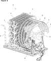
- Figure 2 — is the perspective view of the condenser and the cooling fan disposed in the cooling device of the present invention.
- the cooling device (1) comprises a body, a compressor (2) providing the refrigeration cycle to be performed, a coil shaped condenser (5) having at least one refrigerant tube (3) wherein the refrigerant circulates, a fan (6) which provides the condenser (5) and the compressor (2) to be cooled by blowing air thereon and a machine room (10) wherein the compressor (2), the condenser (5) and the fan (6) operate.
- the condenser (5) disposed in the cooling device (1) of the present invention is composed of two portions and comprises a first portion (7), located in front of the fan (6), the refrigerant tube (3) passing through which is in serpentine form and whereon the air blown by the fan (6) in the axial direction acts, and a second portion (9) integrated to the first portion (7), located around the fan (6), whereon the air blown by the fan (6) in the radial direction acts and having a helical refrigerant tube (8) that is joined with the refrigerant tube (3) extended from the first portion (7), that surrounds the fan (6) along at least the depth (D) of the fan (6) fins in the axial direction.
- the air blown by the fan (6) in the axial direction flows directly to the first portion (7) of the condenser (5) and provides the first portion (7) to be cooled by acting on the serpentine refrigerant tubes (3).
- the fan (6) is of axial type and blows a large portion of the air in the axial direction during its operation; however, the fan (6) inevitably blows some amount of air also in the radial direction.
- the air blown by the fan (6) in the radial direction acts on the helical refrigerant tubes (8) in the second portion (9) surrounding the fan (6) and the air blown by the fan (6) in the radial direction is effectively utilized without using an air guide.
- the cooling device (1) comprises more than one wire (4) disposed on the refrigerant tubes (3), which increases the heat transfer and forms a rigid configuration by being fastened to the refrigerant tubes (3) and which is fastened around the helical refrigerant tube (8) by being extended from the first portion (7) to the second portion (9) of the condenser (5), protecting the fan (6) by forming a cage configuration around the fan (6) together with the helical refrigerant tube (8).
- the wires (4) are provided to be used commonly by the first and the second portions (7, 9), separate wires (4) are not used for the second portion (9) which has a different geometry than that of the first portion (7), ease of production is provided and a rigid configuration is obtained.
- the serpentine refrigerant tube (3) disposed in the first portion (7) of the condenser (5) and the helical refrigerant tube (8) disposed in the second portion (9) thereof are produced by making two separate forms suitable for both portions (7, 9) out of a single-piece metal tube.
- the serpentine refrigerant tube (3) and the helical refrigerant tube (8) are produced separately and joined by welding.
- the cooling device (1) of the present invention since the fan (6) is protected by the helical refrigerant tube (8) surrounding the fan (6) and the wires (4) fastened to the helical refrigerant tube (8), a casing for protecting the fan (6) or a lid for covering the machine room (10) are not required.
- the air blown by the fan (6) in the radial direction is utilized and an additional air guide for directing the air in the axial direction is not required.
- the condenser (5) less number of refrigerant tubes (3, 103) is used in total compared to the known embodiments, the volume occupied by the condenser (5) in the machine room (10) is decreased and the efficiency of the condenser (5) is increased.
Landscapes
- Engineering & Computer Science (AREA)
- Physics & Mathematics (AREA)
- Mechanical Engineering (AREA)
- Thermal Sciences (AREA)
- General Engineering & Computer Science (AREA)
- Chemical & Material Sciences (AREA)
- Combustion & Propulsion (AREA)
- Devices That Are Associated With Refrigeration Equipment (AREA)
Abstract
The present invention relates to a cooling device (1) comprising a body, a compressor (2) providing the refrigeration cycle to be performed, a coil shaped condenser (5) providing the refrigerant to be condensed, having at least one refrigerant tube (3) wherein the refrigerant circulates and more than one wire (4) increasing the heat transfer and forming a rigid configuration by being fastened to the refrigerant tubes (3), a fan (6) which provides the condenser (5) and the compressor (2) to be cooled by blowing air thereon and a machine room (10) wherein the compressor (2), the condenser (5) and the fan (6) operate.
Description
The present invention relates to a cooling device wherein the compressor and the condenser operating in the machine room are cooled by the fan.
In the refrigerant cycle realized in cooling devices, for example in refrigerators, the heat absorbed from the interior of the cooling device is discharged to the outer environment by means of the condenser. In conventional refrigerators, the static type condenser that operates according to the natural heat convection principle is preferred and in no-frost refrigerators, the coil type condenser that operates according to the forced heat convection principle is preferred. In no-frost refrigerators, the compressor and the condenser generally operate in the machine room which is called the cabinet base region and which is situated at the bottom portion of the refrigerator body. The condenser and the compressor are provided to be cooled by means of a fan situated in the machine room. In known embodiments, the fan is generally of axial type and an air guide is disposed around the fan in order to guide the air blown in the axial direction by the fan directly to the condenser. The air guide occupies space in the machine room and due to the turbulences that occur in the air flow, the condenser and the compressor cannot be cooled efficiently. Moreover, the elements operating in the machine room, especially the fan that rotates at high speed, are required to be protected by being closed all around due to safety reasons. In some embodiments, in order to provide security, the fan operates in a casing or the machine room is closed by a lid. The elements such as the fan casing and the machine room lid slow down the air flow and an effective cooling cannot be provided in the condenser and the compressor.
In the cooling device explained in the state of the art International Patent Application No. WO2008040724, the air that is received into the machine room by being sucked from the outer environment by means of a fan is delivered onto a condenser casing which is composed of telescopic bodies and wherein the condenser is situated.
In the refrigerator explained in the United States Patent No. US5592829, the fan disposed between the compressor and the coil shaped condenser directs the ambient air onto the compressor by sucking it from over the condenser.
In the refrigerator explained in the Australian Patent No. AU762033, a partition is disposed between the condenser and the fan and an air guide disposed around the fan is placed in the opening situated on the partition.
The aim of the present invention is the realization of a cooling device comprising a condenser which is provided to be efficiently cooled by the air blown by the fan.
The cooling device realized in order to attain the aim of the present invention, explicated in the first claim and the respective claims thereof, comprises a machine room wherein the compressor and the condenser operate, and the compressor and the condenser are provided to be cooled by means of an axial fan. The condenser comprises two portions with different geometries. The refrigerant flow tube which passes through the first portion is in serpentine form and the air blown by the fan in the axial direction acts thereon. The second portion of the condenser has a helical flow tube which is joined with the flow tube extended from the first portion, and the helical flow tube surrounds the fan along the depth of the fan. The air blown by the fan in the radial direction acts on the second portion surrounding the fan.
In an embodiment of the present invention, some of the heat exchanger wires disposed in the condenser is fastened around the helical flow tube by being extended from the first portion towards the second portion and forms a cage configuration around the fan together with the helical flow tube.
In another embodiment of the present invention, the serpentine and helical flow tubes are produced by forming a single-piece metal tube.
In another embodiment of the present invention, the serpentine and helical flow tubes are produced separately and joined by welding.
In the cooling device of the present invention, a separate casing for protecting the fan or a lid for covering the machine room are not required. The air blown by the fan in the radial direction is effectively utilized without using an air guide, the volume occupied by the condenser is decreased and the efficiency of the condenser is increased.
The cooling device realized in order to attain the aim of the present invention is illustrated in the attached figures, where:
Figure 1 – is the schematic view of the machine room of the cooling device of the present invention.
Figure 2 – is the perspective view of the condenser and the cooling fan disposed in the cooling device of the present invention.
The elements illustrated in the figures are numbered as follows:
- Cooling device
- Compressor
- Refrigerant tube
- Wire
- Condenser
- Fan
- First portion
- Helical refrigerant tube
- Second portion
- Machine room
The cooling device (1) comprises a body, a compressor (2) providing the refrigeration cycle to be performed, a coil shaped condenser (5) having at least one refrigerant tube (3) wherein the refrigerant circulates, a fan (6) which provides the condenser (5) and the compressor (2) to be cooled by blowing air thereon and a machine room (10) wherein the compressor (2), the condenser (5) and the fan (6) operate.
The condenser (5) disposed in the cooling device (1) of the present invention is composed of two portions and comprises a first portion (7), located in front of the fan (6), the refrigerant tube (3) passing through which is in serpentine form and whereon the air blown by the fan (6) in the axial direction acts, and a second portion (9) integrated to the first portion (7), located around the fan (6), whereon the air blown by the fan (6) in the radial direction acts and having a helical refrigerant tube (8) that is joined with the refrigerant tube (3) extended from the first portion (7), that surrounds the fan (6) along at least the depth (D) of the fan (6) fins in the axial direction.
The air blown by the fan (6) in the axial direction flows directly to the first portion (7) of the condenser (5) and provides the first portion (7) to be cooled by acting on the serpentine refrigerant tubes (3). The fan (6) is of axial type and blows a large portion of the air in the axial direction during its operation; however, the fan (6) inevitably blows some amount of air also in the radial direction. The air blown by the fan (6) in the radial direction acts on the helical refrigerant tubes (8) in the second portion (9) surrounding the fan (6) and the air blown by the fan (6) in the radial direction is effectively utilized without using an air guide.
In an embodiment of the present invention, the cooling device (1) comprises more than one wire (4) disposed on the refrigerant tubes (3), which increases the heat transfer and forms a rigid configuration by being fastened to the refrigerant tubes (3) and which is fastened around the helical refrigerant tube (8) by being extended from the first portion (7) to the second portion (9) of the condenser (5), protecting the fan (6) by forming a cage configuration around the fan (6) together with the helical refrigerant tube (8). The wires (4) are provided to be used commonly by the first and the second portions (7, 9), separate wires (4) are not used for the second portion (9) which has a different geometry than that of the first portion (7), ease of production is provided and a rigid configuration is obtained.
In another embodiment of the present invention, the serpentine refrigerant tube (3) disposed in the first portion (7) of the condenser (5) and the helical refrigerant tube (8) disposed in the second portion (9) thereof are produced by making two separate forms suitable for both portions (7, 9) out of a single-piece metal tube.
In another embodiment of the present invention, the serpentine refrigerant tube (3) and the helical refrigerant tube (8) are produced separately and joined by welding.
In the cooling device (1) of the present invention, since the fan (6) is protected by the helical refrigerant tube (8) surrounding the fan (6) and the wires (4) fastened to the helical refrigerant tube (8), a casing for protecting the fan (6) or a lid for covering the machine room (10) are not required. The air blown by the fan (6) in the radial direction is utilized and an additional air guide for directing the air in the axial direction is not required. In the condenser (5), less number of refrigerant tubes (3, 103) is used in total compared to the known embodiments, the volume occupied by the condenser (5) in the machine room (10) is decreased and the efficiency of the condenser (5) is increased.
It is to be understood that the present invention is not limited by the embodiments disclosed above and a person skilled in the art can easily introduce different embodiments. These should be considered within the scope of the protection postulated by the claims of the present invention.
Claims (4)
- A cooling device (1) comprising a compressor (2) providing the refrigeration cycle to be performed, a condenser (5) having at least one refrigerant tube (3) wherein the refrigerant circulates and a fan (6) which provides the condenser (5) and the compressor (2) to be cooled by blowing air thereon, characterized by the condenser (5) comprising a first portion (7) located in front of the fan (6), the refrigerant tube (3) passing through which is in serpentine form and a second portion (9) integrated to the first portion (7), located around the fan (6), having a helical refrigerant tube (8) that is joined with the refrigerant tube (3) extended from the first portion (7), that surrounds the fan (6) along at least the depth (D) of the fan (6) fins in the axial direction..
- A cooling device (1) as in Claim 1, characterized by more than one wire (4) disposed on the refrigerant tubes (3), which is fastened around the helical refrigerant tube (8) by being extended from the first portion (7) to the second portion (9) of the condenser (5), protecting the fan (6) by forming a cage configuration around the fan (6) together with the helical refrigerant tube (8).
- A cooling device (1) as in Claim 1 or 2, characterized by the condenser (5), the serpentine refrigerant tube (3) and the helical refrigerant tube (8) of which are produced by forming a single-piece metal tube.
- A cooling device (1) as in Claim 1 or 2, characterized by the condenser (5), the serpentine refrigerant tube (3) and the helical refrigerant tube (8) of which are produced separately and joined by welding.
Applications Claiming Priority (2)
| Application Number | Priority Date | Filing Date | Title |
|---|---|---|---|
| TRA2010/10875 | 2010-12-24 | ||
| TR201010875 | 2010-12-24 |
Publications (1)
| Publication Number | Publication Date |
|---|---|
| WO2012084486A1 true WO2012084486A1 (en) | 2012-06-28 |
Family
ID=45218716
Family Applications (1)
| Application Number | Title | Priority Date | Filing Date |
|---|---|---|---|
| PCT/EP2011/071865 Ceased WO2012084486A1 (en) | 2010-12-24 | 2011-12-06 | A cooling device comprising a condenser cooled by a fan |
Country Status (1)
| Country | Link |
|---|---|
| WO (1) | WO2012084486A1 (en) |
Cited By (4)
| Publication number | Priority date | Publication date | Assignee | Title |
|---|---|---|---|---|
| JP2016535227A (en) * | 2013-10-11 | 2016-11-10 | リアクション エンジンズ リミテッド | Heat exchanger |
| US20160370118A1 (en) * | 2013-12-09 | 2016-12-22 | Bsh Hausgeraete Gmbh | Condenser, method for fabricating a condenser and cooling appliance having the condenser |
| WO2017202687A1 (en) | 2016-05-25 | 2017-11-30 | Arcelik Anonim Sirketi | A cooling device comprising a condenser cover |
| EP4361538A1 (en) * | 2022-10-27 | 2024-05-01 | Arçelik Anonim Sirketi | A cooling device comprising a pipe holder |
Citations (10)
| Publication number | Priority date | Publication date | Assignee | Title |
|---|---|---|---|---|
| US1709176A (en) * | 1926-12-13 | 1929-04-16 | Mccord Radiator & Mfg Co | Condenser for refrigerating machines |
| US2218596A (en) * | 1935-07-30 | 1940-10-22 | Carrier Corp | Refrigerating apparatus |
| US3251409A (en) * | 1963-01-30 | 1966-05-17 | Heil Quaker Corp | Condenser assembly |
| US4321803A (en) * | 1979-11-23 | 1982-03-30 | Addison Products Company | Multiple air passage condenser |
| US5592829A (en) | 1994-04-21 | 1997-01-14 | Daewoo Electronics Co., Ltd. | Refrigerator provided with a condenser having an improved cooling efficiency |
| AU762033B2 (en) | 1998-08-13 | 2003-06-19 | Lg Electronics Inc. | Cooling fan guide in refrigerator |
| JP2003322456A (en) * | 2002-04-26 | 2003-11-14 | Hitachi Home & Life Solutions Inc | refrigerator |
| US20040216865A1 (en) * | 2003-04-30 | 2004-11-04 | Korea Bundy Corp. | Coil type turn-fin condenser |
| WO2008040724A2 (en) | 2006-10-02 | 2008-04-10 | Arcelik Anonim Sirketi | A cooling device |
| JP2008261615A (en) * | 2007-03-16 | 2008-10-30 | Mitsubishi Electric Corp | Heat exchanger, heat exchanger, refrigerator, air conditioner |
-
2011
- 2011-12-06 WO PCT/EP2011/071865 patent/WO2012084486A1/en not_active Ceased
Patent Citations (10)
| Publication number | Priority date | Publication date | Assignee | Title |
|---|---|---|---|---|
| US1709176A (en) * | 1926-12-13 | 1929-04-16 | Mccord Radiator & Mfg Co | Condenser for refrigerating machines |
| US2218596A (en) * | 1935-07-30 | 1940-10-22 | Carrier Corp | Refrigerating apparatus |
| US3251409A (en) * | 1963-01-30 | 1966-05-17 | Heil Quaker Corp | Condenser assembly |
| US4321803A (en) * | 1979-11-23 | 1982-03-30 | Addison Products Company | Multiple air passage condenser |
| US5592829A (en) | 1994-04-21 | 1997-01-14 | Daewoo Electronics Co., Ltd. | Refrigerator provided with a condenser having an improved cooling efficiency |
| AU762033B2 (en) | 1998-08-13 | 2003-06-19 | Lg Electronics Inc. | Cooling fan guide in refrigerator |
| JP2003322456A (en) * | 2002-04-26 | 2003-11-14 | Hitachi Home & Life Solutions Inc | refrigerator |
| US20040216865A1 (en) * | 2003-04-30 | 2004-11-04 | Korea Bundy Corp. | Coil type turn-fin condenser |
| WO2008040724A2 (en) | 2006-10-02 | 2008-04-10 | Arcelik Anonim Sirketi | A cooling device |
| JP2008261615A (en) * | 2007-03-16 | 2008-10-30 | Mitsubishi Electric Corp | Heat exchanger, heat exchanger, refrigerator, air conditioner |
Cited By (7)
| Publication number | Priority date | Publication date | Assignee | Title |
|---|---|---|---|---|
| JP2016535227A (en) * | 2013-10-11 | 2016-11-10 | リアクション エンジンズ リミテッド | Heat exchanger |
| CN113218210A (en) * | 2013-10-11 | 2021-08-06 | 喷气发动机有限公司 | Heat exchanger |
| US11661888B2 (en) | 2013-10-11 | 2023-05-30 | Reaction Engines Ltd. | Heat exchangers |
| US12158106B2 (en) | 2013-10-11 | 2024-12-03 | Reaction Engines Ltd. | Heat exchangers |
| US20160370118A1 (en) * | 2013-12-09 | 2016-12-22 | Bsh Hausgeraete Gmbh | Condenser, method for fabricating a condenser and cooling appliance having the condenser |
| WO2017202687A1 (en) | 2016-05-25 | 2017-11-30 | Arcelik Anonim Sirketi | A cooling device comprising a condenser cover |
| EP4361538A1 (en) * | 2022-10-27 | 2024-05-01 | Arçelik Anonim Sirketi | A cooling device comprising a pipe holder |
Similar Documents
| Publication | Publication Date | Title |
|---|---|---|
| US11940162B2 (en) | Integrated air conditioner | |
| EP1970656B1 (en) | Refrigerator with air guide duct | |
| KR101578003B1 (en) | Refrigerator | |
| EP2330366A2 (en) | Air conditioner and outdoor unit thereof | |
| JP2004037068A (en) | Kimchi refrigerator | |
| EP2174083A2 (en) | Refrigerator | |
| EP3147579B1 (en) | Outdoor equipment for refrigeration cycle device | |
| WO2016177803A1 (en) | A cooling device comprising a condenser cooled by a fan | |
| JP5423523B2 (en) | refrigerator | |
| KR200313220Y1 (en) | Cooling apparatus for condenser of air conditioner | |
| JP2009002596A (en) | Cooling unit | |
| EP2638340B1 (en) | Refrigerator with cooled machine room | |
| WO2016107687A1 (en) | A cooling device comprising an air guiding apparatus | |
| EP3063481B1 (en) | Refrigeration appliance having an improved defrost water collection receptacle | |
| KR100544716B1 (en) | Water Cooled Air Conditioners | |
| KR20130120022A (en) | Refrigerator | |
| JP2000236998A (en) | Refrigerated showcase | |
| KR20110083913A (en) | Refrigerator | |
| WO2015062654A1 (en) | Heat exchanger assembly for a refrigeration appliance having independent heat exchange circuits | |
| KR200411664Y1 (en) | Flow Structure in the Machine Room of Kimchi Storage | |
| JP4293960B2 (en) | refrigerator | |
| KR200168786Y1 (en) | Chiller of refrigerator machine room | |
| KR100735801B1 (en) | Condenser Structure of Kimchi Storage | |
| KR20250163150A (en) | Outdoor unit of air conditioner | |
| JP2014215022A (en) | Air conditioner indoor unit |
Legal Events
| Date | Code | Title | Description |
|---|---|---|---|
| 121 | Ep: the epo has been informed by wipo that ep was designated in this application |
Ref document number: 11793765 Country of ref document: EP Kind code of ref document: A1 |
|
| NENP | Non-entry into the national phase |
Ref country code: DE |
|
| 122 | Ep: pct application non-entry in european phase |
Ref document number: 11793765 Country of ref document: EP Kind code of ref document: A1 |