WO2012070118A1 - Vehicular power transmission device - Google Patents
Vehicular power transmission device Download PDFInfo
- Publication number
- WO2012070118A1 WO2012070118A1 PCT/JP2010/070900 JP2010070900W WO2012070118A1 WO 2012070118 A1 WO2012070118 A1 WO 2012070118A1 JP 2010070900 W JP2010070900 W JP 2010070900W WO 2012070118 A1 WO2012070118 A1 WO 2012070118A1
- Authority
- WO
- WIPO (PCT)
- Prior art keywords
- torque converter
- rotating member
- shaft
- engine
- power transmission
- Prior art date
Links
Images
Classifications
-
- B—PERFORMING OPERATIONS; TRANSPORTING
- B60—VEHICLES IN GENERAL
- B60W—CONJOINT CONTROL OF VEHICLE SUB-UNITS OF DIFFERENT TYPE OR DIFFERENT FUNCTION; CONTROL SYSTEMS SPECIALLY ADAPTED FOR HYBRID VEHICLES; ROAD VEHICLE DRIVE CONTROL SYSTEMS FOR PURPOSES NOT RELATED TO THE CONTROL OF A PARTICULAR SUB-UNIT
- B60W10/00—Conjoint control of vehicle sub-units of different type or different function
- B60W10/02—Conjoint control of vehicle sub-units of different type or different function including control of driveline clutches
- B60W10/023—Fluid clutches
-
- F—MECHANICAL ENGINEERING; LIGHTING; HEATING; WEAPONS; BLASTING
- F16—ENGINEERING ELEMENTS AND UNITS; GENERAL MEASURES FOR PRODUCING AND MAINTAINING EFFECTIVE FUNCTIONING OF MACHINES OR INSTALLATIONS; THERMAL INSULATION IN GENERAL
- F16H—GEARING
- F16H41/00—Rotary fluid gearing of the hydrokinetic type
- F16H41/24—Details
-
- B—PERFORMING OPERATIONS; TRANSPORTING
- B60—VEHICLES IN GENERAL
- B60K—ARRANGEMENT OR MOUNTING OF PROPULSION UNITS OR OF TRANSMISSIONS IN VEHICLES; ARRANGEMENT OR MOUNTING OF PLURAL DIVERSE PRIME-MOVERS IN VEHICLES; AUXILIARY DRIVES FOR VEHICLES; INSTRUMENTATION OR DASHBOARDS FOR VEHICLES; ARRANGEMENTS IN CONNECTION WITH COOLING, AIR INTAKE, GAS EXHAUST OR FUEL SUPPLY OF PROPULSION UNITS IN VEHICLES
- B60K6/00—Arrangement or mounting of plural diverse prime-movers for mutual or common propulsion, e.g. hybrid propulsion systems comprising electric motors and internal combustion engines ; Control systems therefor, i.e. systems controlling two or more prime movers, or controlling one of these prime movers and any of the transmission, drive or drive units Informative references: mechanical gearings with secondary electric drive F16H3/72; arrangements for handling mechanical energy structurally associated with the dynamo-electric machine H02K7/00; machines comprising structurally interrelated motor and generator parts H02K51/00; dynamo-electric machines not otherwise provided for in H02K see H02K99/00
- B60K6/20—Arrangement or mounting of plural diverse prime-movers for mutual or common propulsion, e.g. hybrid propulsion systems comprising electric motors and internal combustion engines ; Control systems therefor, i.e. systems controlling two or more prime movers, or controlling one of these prime movers and any of the transmission, drive or drive units Informative references: mechanical gearings with secondary electric drive F16H3/72; arrangements for handling mechanical energy structurally associated with the dynamo-electric machine H02K7/00; machines comprising structurally interrelated motor and generator parts H02K51/00; dynamo-electric machines not otherwise provided for in H02K see H02K99/00 the prime-movers consisting of electric motors and internal combustion engines, e.g. HEVs
- B60K6/22—Arrangement or mounting of plural diverse prime-movers for mutual or common propulsion, e.g. hybrid propulsion systems comprising electric motors and internal combustion engines ; Control systems therefor, i.e. systems controlling two or more prime movers, or controlling one of these prime movers and any of the transmission, drive or drive units Informative references: mechanical gearings with secondary electric drive F16H3/72; arrangements for handling mechanical energy structurally associated with the dynamo-electric machine H02K7/00; machines comprising structurally interrelated motor and generator parts H02K51/00; dynamo-electric machines not otherwise provided for in H02K see H02K99/00 the prime-movers consisting of electric motors and internal combustion engines, e.g. HEVs characterised by apparatus, components or means specially adapted for HEVs
- B60K6/36—Arrangement or mounting of plural diverse prime-movers for mutual or common propulsion, e.g. hybrid propulsion systems comprising electric motors and internal combustion engines ; Control systems therefor, i.e. systems controlling two or more prime movers, or controlling one of these prime movers and any of the transmission, drive or drive units Informative references: mechanical gearings with secondary electric drive F16H3/72; arrangements for handling mechanical energy structurally associated with the dynamo-electric machine H02K7/00; machines comprising structurally interrelated motor and generator parts H02K51/00; dynamo-electric machines not otherwise provided for in H02K see H02K99/00 the prime-movers consisting of electric motors and internal combustion engines, e.g. HEVs characterised by apparatus, components or means specially adapted for HEVs characterised by the transmission gearings
- B60K6/365—Arrangement or mounting of plural diverse prime-movers for mutual or common propulsion, e.g. hybrid propulsion systems comprising electric motors and internal combustion engines ; Control systems therefor, i.e. systems controlling two or more prime movers, or controlling one of these prime movers and any of the transmission, drive or drive units Informative references: mechanical gearings with secondary electric drive F16H3/72; arrangements for handling mechanical energy structurally associated with the dynamo-electric machine H02K7/00; machines comprising structurally interrelated motor and generator parts H02K51/00; dynamo-electric machines not otherwise provided for in H02K see H02K99/00 the prime-movers consisting of electric motors and internal combustion engines, e.g. HEVs characterised by apparatus, components or means specially adapted for HEVs characterised by the transmission gearings with the gears having orbital motion
-
- B—PERFORMING OPERATIONS; TRANSPORTING
- B60—VEHICLES IN GENERAL
- B60K—ARRANGEMENT OR MOUNTING OF PROPULSION UNITS OR OF TRANSMISSIONS IN VEHICLES; ARRANGEMENT OR MOUNTING OF PLURAL DIVERSE PRIME-MOVERS IN VEHICLES; AUXILIARY DRIVES FOR VEHICLES; INSTRUMENTATION OR DASHBOARDS FOR VEHICLES; ARRANGEMENTS IN CONNECTION WITH COOLING, AIR INTAKE, GAS EXHAUST OR FUEL SUPPLY OF PROPULSION UNITS IN VEHICLES
- B60K6/00—Arrangement or mounting of plural diverse prime-movers for mutual or common propulsion, e.g. hybrid propulsion systems comprising electric motors and internal combustion engines ; Control systems therefor, i.e. systems controlling two or more prime movers, or controlling one of these prime movers and any of the transmission, drive or drive units Informative references: mechanical gearings with secondary electric drive F16H3/72; arrangements for handling mechanical energy structurally associated with the dynamo-electric machine H02K7/00; machines comprising structurally interrelated motor and generator parts H02K51/00; dynamo-electric machines not otherwise provided for in H02K see H02K99/00
- B60K6/20—Arrangement or mounting of plural diverse prime-movers for mutual or common propulsion, e.g. hybrid propulsion systems comprising electric motors and internal combustion engines ; Control systems therefor, i.e. systems controlling two or more prime movers, or controlling one of these prime movers and any of the transmission, drive or drive units Informative references: mechanical gearings with secondary electric drive F16H3/72; arrangements for handling mechanical energy structurally associated with the dynamo-electric machine H02K7/00; machines comprising structurally interrelated motor and generator parts H02K51/00; dynamo-electric machines not otherwise provided for in H02K see H02K99/00 the prime-movers consisting of electric motors and internal combustion engines, e.g. HEVs
- B60K6/42—Arrangement or mounting of plural diverse prime-movers for mutual or common propulsion, e.g. hybrid propulsion systems comprising electric motors and internal combustion engines ; Control systems therefor, i.e. systems controlling two or more prime movers, or controlling one of these prime movers and any of the transmission, drive or drive units Informative references: mechanical gearings with secondary electric drive F16H3/72; arrangements for handling mechanical energy structurally associated with the dynamo-electric machine H02K7/00; machines comprising structurally interrelated motor and generator parts H02K51/00; dynamo-electric machines not otherwise provided for in H02K see H02K99/00 the prime-movers consisting of electric motors and internal combustion engines, e.g. HEVs characterised by the architecture of the hybrid electric vehicle
- B60K6/48—Parallel type
-
- B—PERFORMING OPERATIONS; TRANSPORTING
- B60—VEHICLES IN GENERAL
- B60W—CONJOINT CONTROL OF VEHICLE SUB-UNITS OF DIFFERENT TYPE OR DIFFERENT FUNCTION; CONTROL SYSTEMS SPECIALLY ADAPTED FOR HYBRID VEHICLES; ROAD VEHICLE DRIVE CONTROL SYSTEMS FOR PURPOSES NOT RELATED TO THE CONTROL OF A PARTICULAR SUB-UNIT
- B60W10/00—Conjoint control of vehicle sub-units of different type or different function
- B60W10/04—Conjoint control of vehicle sub-units of different type or different function including control of propulsion units
- B60W10/08—Conjoint control of vehicle sub-units of different type or different function including control of propulsion units including control of electric propulsion units, e.g. motors or generators
-
- B—PERFORMING OPERATIONS; TRANSPORTING
- B60—VEHICLES IN GENERAL
- B60K—ARRANGEMENT OR MOUNTING OF PROPULSION UNITS OR OF TRANSMISSIONS IN VEHICLES; ARRANGEMENT OR MOUNTING OF PLURAL DIVERSE PRIME-MOVERS IN VEHICLES; AUXILIARY DRIVES FOR VEHICLES; INSTRUMENTATION OR DASHBOARDS FOR VEHICLES; ARRANGEMENTS IN CONNECTION WITH COOLING, AIR INTAKE, GAS EXHAUST OR FUEL SUPPLY OF PROPULSION UNITS IN VEHICLES
- B60K6/00—Arrangement or mounting of plural diverse prime-movers for mutual or common propulsion, e.g. hybrid propulsion systems comprising electric motors and internal combustion engines ; Control systems therefor, i.e. systems controlling two or more prime movers, or controlling one of these prime movers and any of the transmission, drive or drive units Informative references: mechanical gearings with secondary electric drive F16H3/72; arrangements for handling mechanical energy structurally associated with the dynamo-electric machine H02K7/00; machines comprising structurally interrelated motor and generator parts H02K51/00; dynamo-electric machines not otherwise provided for in H02K see H02K99/00
- B60K6/20—Arrangement or mounting of plural diverse prime-movers for mutual or common propulsion, e.g. hybrid propulsion systems comprising electric motors and internal combustion engines ; Control systems therefor, i.e. systems controlling two or more prime movers, or controlling one of these prime movers and any of the transmission, drive or drive units Informative references: mechanical gearings with secondary electric drive F16H3/72; arrangements for handling mechanical energy structurally associated with the dynamo-electric machine H02K7/00; machines comprising structurally interrelated motor and generator parts H02K51/00; dynamo-electric machines not otherwise provided for in H02K see H02K99/00 the prime-movers consisting of electric motors and internal combustion engines, e.g. HEVs
- B60K6/42—Arrangement or mounting of plural diverse prime-movers for mutual or common propulsion, e.g. hybrid propulsion systems comprising electric motors and internal combustion engines ; Control systems therefor, i.e. systems controlling two or more prime movers, or controlling one of these prime movers and any of the transmission, drive or drive units Informative references: mechanical gearings with secondary electric drive F16H3/72; arrangements for handling mechanical energy structurally associated with the dynamo-electric machine H02K7/00; machines comprising structurally interrelated motor and generator parts H02K51/00; dynamo-electric machines not otherwise provided for in H02K see H02K99/00 the prime-movers consisting of electric motors and internal combustion engines, e.g. HEVs characterised by the architecture of the hybrid electric vehicle
- B60K6/48—Parallel type
- B60K2006/4825—Electric machine connected or connectable to gearbox input shaft
-
- B—PERFORMING OPERATIONS; TRANSPORTING
- B60—VEHICLES IN GENERAL
- B60W—CONJOINT CONTROL OF VEHICLE SUB-UNITS OF DIFFERENT TYPE OR DIFFERENT FUNCTION; CONTROL SYSTEMS SPECIALLY ADAPTED FOR HYBRID VEHICLES; ROAD VEHICLE DRIVE CONTROL SYSTEMS FOR PURPOSES NOT RELATED TO THE CONTROL OF A PARTICULAR SUB-UNIT
- B60W2510/00—Input parameters relating to a particular sub-units
- B60W2510/02—Clutches
-
- F—MECHANICAL ENGINEERING; LIGHTING; HEATING; WEAPONS; BLASTING
- F16—ENGINEERING ELEMENTS AND UNITS; GENERAL MEASURES FOR PRODUCING AND MAINTAINING EFFECTIVE FUNCTIONING OF MACHINES OR INSTALLATIONS; THERMAL INSULATION IN GENERAL
- F16H—GEARING
- F16H45/00—Combinations of fluid gearings for conveying rotary motion with couplings or clutches
- F16H2045/002—Combinations of fluid gearings for conveying rotary motion with couplings or clutches comprising a clutch between prime mover and fluid gearing
-
- F—MECHANICAL ENGINEERING; LIGHTING; HEATING; WEAPONS; BLASTING
- F16—ENGINEERING ELEMENTS AND UNITS; GENERAL MEASURES FOR PRODUCING AND MAINTAINING EFFECTIVE FUNCTIONING OF MACHINES OR INSTALLATIONS; THERMAL INSULATION IN GENERAL
- F16H—GEARING
- F16H45/00—Combinations of fluid gearings for conveying rotary motion with couplings or clutches
- F16H45/02—Combinations of fluid gearings for conveying rotary motion with couplings or clutches with mechanical clutches for bridging a fluid gearing of the hydrokinetic type
-
- Y—GENERAL TAGGING OF NEW TECHNOLOGICAL DEVELOPMENTS; GENERAL TAGGING OF CROSS-SECTIONAL TECHNOLOGIES SPANNING OVER SEVERAL SECTIONS OF THE IPC; TECHNICAL SUBJECTS COVERED BY FORMER USPC CROSS-REFERENCE ART COLLECTIONS [XRACs] AND DIGESTS
- Y02—TECHNOLOGIES OR APPLICATIONS FOR MITIGATION OR ADAPTATION AGAINST CLIMATE CHANGE
- Y02T—CLIMATE CHANGE MITIGATION TECHNOLOGIES RELATED TO TRANSPORTATION
- Y02T10/00—Road transport of goods or passengers
- Y02T10/60—Other road transportation technologies with climate change mitigation effect
- Y02T10/62—Hybrid vehicles
-
- Y—GENERAL TAGGING OF NEW TECHNOLOGICAL DEVELOPMENTS; GENERAL TAGGING OF CROSS-SECTIONAL TECHNOLOGIES SPANNING OVER SEVERAL SECTIONS OF THE IPC; TECHNICAL SUBJECTS COVERED BY FORMER USPC CROSS-REFERENCE ART COLLECTIONS [XRACs] AND DIGESTS
- Y10—TECHNICAL SUBJECTS COVERED BY FORMER USPC
- Y10S—TECHNICAL SUBJECTS COVERED BY FORMER USPC CROSS-REFERENCE ART COLLECTIONS [XRACs] AND DIGESTS
- Y10S903/00—Hybrid electric vehicles, HEVS
- Y10S903/902—Prime movers comprising electrical and internal combustion motors
Definitions
- the present invention relates to a structure of a vehicle power transmission device that constitutes a part of a power transmission path between an engine and driving wheels.
- An input-side rotating member provided with a plurality of pump blades, an output-side rotating member provided with a plurality of turbine blades for receiving a fluid flow from the pump blades, and a stator disposed between the pump blades and the turbine blades 2.
- a vehicle power transmission device that includes a torque converter having a stator provided with blades in a power transmission path between an engine and driving wheels. For example, those described in Patent Documents 1 to 4.
- the conventional vehicle power transmission device in order to improve the mounting property on the vehicle, it is desired to further shorten the axial total length of the vehicle power transmission device.
- the distance in the axial direction occupied by the torque converter in the vehicle power transmission device can be reduced.
- there is a limit to reducing the thickness of the constituent members in addition, the following is mentioned as one of the factors which a torque converter becomes long in the axial direction.
- the one-way clutch housed in the outer shell cover of the torque converter and interposed between the stator and the case member for example, has a predetermined width dimension in the axial direction in order to ensure a predetermined torque capacity. Is in need.
- the present invention has been made against the background of the above circumstances, and an object of the present invention is a vehicle power transmission device provided with a torque converter, which can reduce the overall axial length. It is to provide a transmission device.
- the gist of the present invention is that: (a) an input side rotating member provided with a plurality of pump blades and an output provided with a plurality of turbine blades for receiving a fluid flow from the pump blades
- Vehicle power transmission comprising a torque converter having a stator provided with a stator blade disposed between a side rotating member and the pump blade and turbine blade in a power transmission path between an engine and a drive wheel
- B a first chamber that accommodates the torque converter divided by a partition provided on a side opposite to the engine of the torque converter and a partition formed on the side opposite to the torque converter
- the first chamber and the second chamber include an inner peripheral surface of the partition wall and the input-side rotating member.
- the input-side rotating member that is oil-tightly isolated from each other by an oil seal that oil-tightly seals a gap between the cylindrical rotary shaft projecting toward the second chamber.
- a thrust bearing is disposed between the partition wall side wall portion and the stator, and (e) the thrust bearing is partially or relative to the oil seal as viewed in a direction perpendicular to the axis of the torque converter. It is that all are provided so that it may overlap.
- the thrust bearing and the members disposed adjacent thereto such as the stator and the case, for example, Since the one-way clutch interposed between the member and the like can be arranged close to the partition wall side, the distance between the entire outer shell cover of the torque converter housing the thrust bearing and the one-way clutch and the partition wall can be reduced. Can do. Therefore, the overall axial length of the vehicle power transmission device can be shortened.
- the input-side rotating member has a part of a radial position corresponding to the thrust bearing in the side wall portion on the partition side of the input-side rotating member over the entire circumference.
- the thrust bearing is disposed in the annular protrusion.
- the torque converter includes an engine intermittent clutch that selectively connects a crankshaft of the engine and an input side rotating member of the torque converter at the engine side of the output side rotating member.
- the oil seal and the thrust bearing are partially or entirely overlapped when viewed in a direction parallel to the shaft center.
- the engine intermittent clutch can be made compact in a space vacated on the engine side in the outer shell cover of the torque converter. Can be arranged.
- the first rotary shaft is disposed on a second axis parallel to the axis, and the rotary shaft for motor connection connected to the cylindrical rotary shaft is connected to the cylindrical rotary shaft.
- An electric motor coupled to the input-side rotating member; and
- the partition has a support portion formed by protruding a part of a radial position over the entire circumference toward the second chamber side,
- the rotating member for connecting the motor is rotatably supported by a support part of the partition wall via a bearing, and (d) the annular projecting part is positioned on the inner peripheral side of the support part of the partition wall.
- the vehicle fuel efficiency can be improved by, for example, assisting the output of the engine with the electric motor when the vehicle is driven by the engine, or stopping the engine and driving the vehicle with the electric motor.
- the thrust bearing and the The one-way clutch can be arranged close to the partition wall side.
- a transmission mechanism is provided on the side opposite to the engine with respect to the torque converter in the axial direction, and transmits the power from the torque converter to the drive wheels.
- the output-side rotating member is connected to the input shaft of the transmission mechanism on the transmission mechanism side with respect to the pump blade in the axial direction
- the stator is connected to the stator shaft via a one-way clutch.
- a connecting portion of the inner race of the one-way clutch with the stator shaft and a connecting portion of the output-side rotating member with the input shaft are viewed in a direction perpendicular to the axis.
- the thrust bearing and the oil seal are partially or entirely overlapped with each other.
- the connecting portion of the output side rotating member with the input shaft and the connecting portion of the one-way clutch inner race stator shaft are provided outside the outer cover of the torque converter in the axial direction. . Therefore, the axial length of the outer shell cover can be shortened compared to the case where each of the connecting portions is provided in the outer shell cover. Can be shortened.
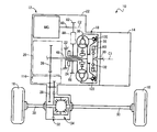
- FIG. 1 is a diagram illustrating a power transmission path from an engine as a driving force source of a vehicle to a drive wheel via a power transmission device in a vehicle including the vehicle power transmission device according to an embodiment of the present invention. It is sectional drawing showing the principal part of the power transmission device of FIG. It is a figure which expands and shows the III arrow part enclosed with the dashed-dotted line of FIG. It is sectional drawing which shows the IV-IV arrow part cross section of FIG. It is sectional drawing which shows the VV arrow part cross section of FIG.
- FIG. 1 shows a vehicle 10 having a vehicle power transmission device 12 (hereinafter referred to as “power transmission device 12”) according to an embodiment of the present invention. It is a figure showing the power transmission path
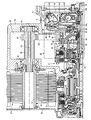
- FIG. 2 is a cross-sectional view showing the main part of the power transmission device 12, that is, the torque converter 18, the automatic transmission 20, the electric motor MG, and the like.
- the first axis C1 is an axis of the torque converter 18 and the automatic transmission 20 or the like. In FIG. 2, the lower half of the first axis C1 is omitted.
- the power transmission device 12 includes a transaxle case (case) 22 that is attached to a vehicle body by, for example, bolting, and the like between the engine 14 and the drive wheels 16 in the transaxle case 22. And a torque converter 18, an oil pump 24, and an automatic transmission 20 that are arranged in series from the engine 14 side on the first axis C1.
- the power transmission device 12 is disposed on a second axis C2 parallel to the first axis C1, and is connected to an input side rotating member (a rear cover 38 described later) of the torque converter 18 so as to be able to transmit power.
- MG is provided.
- the second axis C2 corresponds to a second axis parallel to the axis of the torque converter 18.
- the power transmission device 12 is provided integrally with a rotation shaft parallel to the first axis C1 in the transaxle case 22, and a counter driven gear 28 that meshes with an output gear 26 that is an output member of the automatic transmission 20.
- a dynamic gear device 34 is provided integrally with a rotation shaft parallel to the first axis C1 in the transaxle case 22, and a counter driven gear 28 that meshes with an output gear 26 that is an output member of the automatic transmission 20.
- the power transmission device 12 configured in this way is placed together with the engine 14 in front of, for example, a front wheel drive type, that is, FF (front engine / front drive) type vehicle 10.
- Vehicle 10 is driven by at least one of engine 14 and electric motor MG.
- the power from the engine 14 and the electric motor MG is sequentially transmitted through the torque converter 18, the automatic transmission 20, the counter driven gear 28, the final gear pair 32, the differential gear device 34, and the pair of axles 30. Each is transmitted to the pair of drive wheels 16.
- the automatic transmission 20 is a well-known multi-stage transmission, and is disposed on the opposite side of the engine 14 with respect to the torque converter 18 in the direction of the first axis C1, and the power input from the torque converter 18 is transferred to the subsequent stage.
- the transmission is equivalent to the transmission mechanism in the present invention.
- the torque converter 18 is a fluid transmission device that constitutes a part of a power transmission path between the engine 14 and the drive wheels 16. As shown in FIG. 2, the torque converter 18 is provided in order from the engine 14 side on the first axis C ⁇ b> 1 and is integrally coupled to each other, and is provided rotatably around the first axis C ⁇ b> 1.
- the front cover 36 and the rear cover 38 are provided.
- the front cover 36 is a bottomed cylindrical member that opens toward the automatic transmission 20, and the rear cover 38 is curved at the outer peripheral end toward the engine 14, that is, toward the front cover 36. It is a disk-shaped member fixed to the opening end by welding, for example.
- the front cover 36 and the rear cover 38 function as input side rotating members that are rotated by the power from the engine 14 being input via the engine intermittent clutch K0.
- a plurality of pump blades 40 arranged in the circumferential direction are fixed inside the rear cover 38.
- the torque converter 18 is disposed in a circumferential direction on the outer peripheral portion of the disc portion 42c coupled to the outer peripheral portion of the flange portion 42b by a rivet in a state of being opposed to the pump blade 40 on the rear cover 38 side of the pump blade 40.
- a turbine 42 provided with a plurality of turbine blades 44 arranged and receiving a fluid flow from the pump blade 40, and a stator 46 provided with a stator blade 45 disposed between the pump blade 40 and the turbine blade 44.
- the turbine 42 is caused to function as an output side rotating member of the torque converter 18 and is connected to the outer peripheral surface of the input shaft 48 of the automatic transmission 20 so as not to be relatively rotatable by spline fitting.
- the front cover 36 and the rear cover 38 each contain a pump blade 40, a turbine blade 44, a turbine 42, a stator blade 45, a stator 46, and a fluid that flows from the pump blade 40 to the turbine blade 44. 18 functions as an outer shell cover.
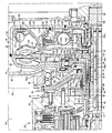
- FIG. 3 is an enlarged view showing a portion indicated by an arrow III surrounded by a one-dot chain line in FIG.
- a well-known internal gear type oil pump 24 is disposed between the torque converter 18 and the automatic transmission 20.
- the oil pump 24 includes a pump cover 50 as a non-rotating member fixed to the transaxle case 22, and a pump body disposed on the rear cover 38 side of the pump cover 50 and fixed integrally to the pump cover 50. 52, and a drive gear 54 and a driven gear 56 which are internal gear pairs meshed with each other and rotatably accommodated in a pump chamber formed by the pump cover 50 and the pump body 52.
- the oil pump 24 configured in this manner is driven to rotate by a tubular pump drive shaft 58 that is concentric with the input shaft 48 and is larger in diameter than the input shaft 48 and protrudes from the rear cover 38 toward the automatic transmission 20 side. It is like that.
- the tubular pump drive shaft 58 is inserted through a through hole 60 formed in the pump body 52 and is connected to the drive gear 54 so as not to be relatively rotatable.
- a tubular stator shaft 62 that is a non-rotating member that is concentric with the input shaft 48, has a larger diameter than the input shaft 48, and a smaller diameter than the tubular pump drive shaft 58 is relative to the pump cover 50. It is fixed so that it cannot rotate.
- the stator 46 of the torque converter 18 includes a one-way clutch 64 and a tubular connecting shaft 64b that protrudes in the direction of the first axis C1 from the inner peripheral edge of the disk-shaped inner race 64a of the one-way clutch 64.
- the stator shaft 62 is a non-rotating member.
- the tubular connecting shaft 64 b is a cylindrical member having a larger diameter than the input shaft 48 and the stator shaft 62 and a smaller diameter than the tubular pump drive shaft 58.
- the one-way clutch 64 has a torque capacity sufficient to prevent reverse rotation of the stator 46 when the torque converter 18 amplifies the torque, and the direction of the first axis C1 is larger than the thickness of the stator 46 and the inner race 64a.
- a sprag 64c having a predetermined dimension is provided. For this reason, the one-way clutch 64 is provided so as to protrude from the stator 46 and the inner race 64a toward the automatic transmission 18 side.
- the tip of the tubular connecting shaft 64b protruding from the inner peripheral edge of the inner race 64a is more automatically shifted than the pump blade 40 in the direction perpendicular to the first axis C1, as indicated by an arrow A in FIG.
- the end of the stator shaft 62 is connected to the end of the stator shaft 62 by spline fitting so as not to be relatively rotatable.
- the connecting portion (spline fitting portion) of the tubular connecting shaft 64b with the stator shaft 62 is provided so as to partially overlap the pump body 52 of the oil pump 24 when viewed in a direction orthogonal to the first axis C1. It has been.
- the pump body 52 of the oil pump 24 is a member disposed at a position closer to the automatic transmission 20 than the pump blade 40 in the direction of the first axis C1, that is, a position closer to the automatic transmission 20 than the outer shell cover of the torque converter 18. It is.
- the input shaft 48 of the automatic transmission 20 is rotatably supported by the stator shaft 62 via a bush (bearing member) 66 on the inner peripheral side of the stator shaft 62.
- the turbine 42 of the torque converter 18 includes a cylindrical boss portion 42 a that is connected to the outer peripheral portion of the input shaft 48 of the automatic transmission 20 so as not to be relatively rotatable by spline fitting, and the engine 14 of the inner race 64 a of the one-way clutch 64.
- On the side there is a flange portion 42b projecting radially outward from a part of the outer peripheral surface of the boss portion 42a, and a disc portion 42c riveted to the outer peripheral portion of the flange portion 42b.
- the boss portion 42a is located on the automatic transmission 20 side relative to the pump blade 40 in the direction of the first axis C1, that is, on the automatic transmission 20 side relative to the outer shell cover of the torque converter 18. It is connected to the input shaft 48 by a non-rotatable fitting at a position.
- boss portion 42a of the turbine 42 is connected to the input shaft 48 at a position closer to the automatic transmission 20 than the position of the rear cover 38 where the pump blade 40 is fixed in the first axis C1 direction.
- stator shaft 62 is fitted to the tubular connecting shaft 64b of the one-way clutch 64 in a relatively non-rotatable manner at a position where the stator shaft 62 partially overlaps the connecting portion with the input shaft 48 of the turbine 42 in the first axial center C1 direction view. It is connected.
- connecting portion of the turbine 42 to the input shaft 48 is provided so as to partially overlap the pump body 52 of the oil pump 24 when viewed in a direction orthogonal to the first axis C1.
- the bush 66 is located at the position of the automatic transmission 20 side relative to the connection position with the input shaft 48 of the turbine 42 in the first axis C1 direction, that is, at the position of the automatic transmission 20 side relative to the outer shell cover of the torque converter 18. It is provided so as to partially overlap the pump body 52 and the drive gear 54 of the oil pump 24 when viewed in a direction perpendicular to the single axis C1.
- the transaxle case 22 has a first chamber R1 for accommodating the torque converter 18 and the like, and a second chamber R2 for accommodating the automatic transmission 20, the electric motor MG, the oil pump 24, and the like.
- the first chamber R1 and the second chamber R2 are divided by a partition wall 68 provided between the rear cover 38 of the torque converter 18 and the pump body 52 of the oil pump 24 on the outer peripheral side of the tubular pump drive shaft 58.
- the oil seal 70 seals the gap between the inner peripheral surface of the through hole 69 formed in the partition wall 68 through which the tubular pump drive shaft 58 is inserted and the outer peripheral surface of the tubular pump drive shaft 58. It is oil-tightly sealed.
- the side surface of the pump body 52 on the rear cover 38 side is inclined in a tapered manner toward the pump cover 50 side, that is, the side away from the rear cover 38 as it goes radially outward.
- the inner peripheral portion 68 a of the partition wall 68 is inclined to the pump body 52 side, that is, the side away from the rear cover 38 as it goes outward in the radial direction, like the side surface of the pump body 52.
- the partition wall 68 and the oil seal 70 are members disposed at a position closer to the automatic transmission 20 than the pump blade 40 in the direction of the first axis C1, that is, a position closer to the automatic transmission 20 than the outer shell cover of the torque converter 18. is there.
- the connecting portion of the turbine 42 with the input shaft 48 is provided so as to partially overlap the oil seal 70 and the partition wall 68 when viewed in a direction orthogonal to the first axis C1.
- the electric motor MG is a so-called motor generator having a motor function and a power generation function.
- the electric motor MG includes an electric motor stator 72 fixed to the inner wall surface of the transaxle case 22 by, for example, a bolt, and a second shaft parallel to the first axis C ⁇ b> 1 on the inner peripheral side of the electric motor stator 72.
- An electric motor output shaft 74 provided rotatably around the center C ⁇ b> 2 and an electric motor rotor 76 fixed to the outer peripheral portion of the electric motor output shaft 74 on the inner peripheral side of the electric motor stator 72 are provided.
- the motor output shaft 74 is made relatively non-rotatable by, for example, spline fitting to a power transmission rotating shaft 80 rotatably supported around the second axis C2 by the transaxle case 22 via a pair of first bearings 78. It is connected.
- the power transmission rotating shaft 80 includes a first motor connecting gear 82 provided integrally on the outer periphery of the power transmitting rotating shaft 80 and a motor connecting rotating member 84 connected to the tubular pump drive shaft 58. It is connected to a motor connecting rotating member 84 through an endless annular transmission chain 88 wound around a second motor connecting gear 86 on the outer periphery so as to be able to transmit power.
- the first motor coupling gear 82 and the second motor coupling gear 86 are gears for transmitting power from the motor MG to the tubular pump drive shaft 58.
- the electric motor MG is operatively applied to the rear cover 38 which is an input side rotation member of the torque converter 18 through the power transmission rotation shaft 80, the transmission chain 88, the motor connection rotation member 84, and the tubular pump drive shaft 58 in order. It is connected to.
- the second motor connecting gear 86 is positioned on the automatic transmission 20 side with respect to the pump blade 40 in the direction of the first axis C ⁇ b> 1, i. It is arranged at the side position.
- the connecting portion of the turbine 42 to the input shaft 48 is provided so as to partially overlap the second motor connecting gear 86 when viewed in a direction orthogonal to the first axis C1.
- the rotation member 84 for motor connection is a second motor connection gear that is rotatably supported around the first axis C ⁇ b> 1 via a second bearing 90 by a support portion 68 b formed at a radial intermediate portion of the partition wall 68. 86 and a flange-like connecting member 92 that connects the second motor connecting gear 86 and the tubular pump drive shaft 58.
- the support portion 68b of the partition wall 68 is formed by projecting a part of the radial position located on the outer peripheral side of the inner peripheral portion 68a of the partition wall 68 toward the second chamber R2 side over the entire periphery.
- the motor connecting rotary member 84 is rotatably supported by the support portion 68 b of the partition wall 68 through the second bearing 90 on the inner peripheral surface of the second motor connecting gear 86.
- the second bearing 90 and the support portion 68b are arranged in the automatic transmission 20 side position with respect to the pump blade 40 in the direction of the first axis C1, that is, in the automatic transmission 20 side position with respect to the outer shell cover of the torque converter 18. It is installed.
- the connecting portion of the turbine 42 to the input shaft 48 is provided so as to partially overlap the second bearing 90 and the support portion 68b of the partition wall 68 when viewed in a direction orthogonal to the first axis C1.
- the connecting member 92 of the motor connecting rotating member 84 is relatively rotated by spline fitting to the outer peripheral portion of the tubular pump drive shaft 58 on the inner peripheral side of the through hole 60 of the pump body 52. It has a cylindrical boss portion 92a that is impossiblely connected.
- the connecting member 92 projects radially outward from one end of the boss 92a on the partition wall 68 side, and is adjacent to the side surface of the pump body 52 and the partition wall 68 provided adjacent to each other in the direction of the first axis C1.
- a flange portion 92b that is inclined toward the pump body 52 side, that is, away from the rear cover 38 toward the outer side in the radial direction and whose outer peripheral end portion is connected to the second motor connecting gear 86 by spline fitting is provided.
- the connection portion of the turbine 42 with the input shaft 48 partially overlaps with the connection portion (splan fitting portion) of the connection member 92 with the tubular pump drive shaft 58 in a direction perpendicular to the first axis C1. Is provided.
- a first thrust bearing 94 is disposed between the side wall portion of the rear cover 38 on the partition wall 68 side and the stator 46, and the rear cover 38 and the stator 46 can be rotated relative to each other via the first thrust bearing 94. It is arranged.
- a second thrust bearing 96 is interposed between the stator 46 and the flange portion 42 b of the turbine 42, and the stator 46 and the turbine 42 can rotate relative to each other via the second thrust bearing 96. It is arranged.
- An annular groove 98 is formed on the inner peripheral side of the support portion 68 b of the partition wall 68.
- the rear cover 38 has a radial portion corresponding to the first thrust bearing 94 on the side wall portion of the rear cover 38 on the partition wall 68 side toward the inner peripheral portion 68a side of the partition wall 68, that is, on the annular groove 98 side. It has the annular protrusion part 38a which protrudes to.
- the annular protrusion 38 a is positioned in the annular groove 98 on the inner peripheral side of the support portion 68 b of the partition wall 68.
- the first thrust bearing 94 and a portion of the one-way clutch 64 protruding from the stator 46 and the inner race 64a are accommodated inside the annular protrusion 38a.
- the one-way clutch 64 is provided so as to protrude from the stator 46 and the inner race 64a toward the automatic transmission 18 side.
- the first thrust bearing 94 is provided so as to partially overlap the inner peripheral portion 68a, the support portion 68b, and the oil seal 70 of the partition wall 68 when viewed in the direction orthogonal to the first axis C1. Yes.
- the connecting portion of the turbine 42 to the input shaft 48 and the connecting portion of the tubular connecting shaft 64b to the stator shaft 62 are in relation to the first thrust bearing 94 and the oil seal 70 in the direction perpendicular to the first axis C1. Are partly overlapped.
- the engine connecting shaft 100 is connected to the output end of the crankshaft 99, which is the output shaft of the engine 14, by, for example, spline fitting.
- the engine connecting shaft 100 is provided concentrically with the input shaft 48, and the tip end portion of the input shaft 48 of the automatic transmission 20 is a cylindrical shaft end portion 100 a opposite to the crankshaft 99 of the engine connecting shaft 100. Is fitted into a fitting hole formed on the inner peripheral side of the inner peripheral side so as to be relatively rotatable, and is rotatably supported by the cylindrical shaft end portion 100a.
- the engine connecting shaft 100 has a flange portion 100b that protrudes radially outward from the cylindrical shaft end portion 100a.
- the flange portion 100 b is provided with a first damper 102 inserted in a power transmission path between the crankshaft 99 of the engine 14 and the front cover 36 of the torque converter 18.
- the first damper 102 includes a damper elastic member 103 made of a spring, rubber, or the like interposed between the input / output members, and generates a torsion according to the transmission torque between the input / output members to cause an impact or pulsation. Is a shock absorber.
- the engine torque is transmitted to the torque converter 18 while the pulsation is suppressed by the first damper 102.
- the first damper 102 is also a damper inserted in a power transmission path between the engine 14 and the electric motor MG.
- the torque converter 18 is arranged on the engine 14 side from the turbine 42 and accommodates the engine cover clutch K0 for selectively connecting the crankshaft 99 of the engine 14 and the front cover 36 of the torque converter 18 in the front cover 36. It is prepared in the state that was done.
- the engine interrupting clutch K0 is connected to the crankshaft 99 via the first damper 102, and functions as an output member of the first damper 102, and the front of the torque converter 18 on the outer peripheral side of the clutch hub 104.
- a cylindrical clutch drum 106 that is integrally fixed to the cover 36, and a gap between the clutch hub 104 and the clutch drum 106 are disposed so as to overlap each other in a direction parallel to the first axis C1. And a pair of first friction plates 108 engaged with the clutch drum 106 so as not to rotate relative to each other, and a pair of first friction plates 108 disposed between the pair of first friction plates 108 and engaged with the clutch hub 104 so as not to rotate relative to each other.
- the second friction plate 110, the first friction plate 108 and the second friction plate 110 are connected to each other.
- the first friction plate 108 and the second friction plate 110 are frictionally engaged with each other by pressing in the screw direction, that is, in the direction parallel to the first axis C1, and the clutch hub 104 and the clutch drum 106 are connected to each other.
- a wet multi-plate clutch provided with a hydraulic actuator 112.
- the engine intermittent clutch K0 includes a friction surface between one of the pair of first friction plates 108 and the second friction plate 110, and a friction between the other of the pair of first friction plates 108 and the second friction plate 110. Torque is transmitted through each surface.
- the engine intermittent clutch K0 connects the clutch hub 104 and the clutch drum 106 to each other via two friction surfaces.
- the engine intermittent clutch K0 is disposed on the inner peripheral side of a lockup clutch 120, which will be described later, and is provided so as to partially overlap the lockup clutch 120 when viewed in a direction perpendicular to the first axis C
- the hydraulic actuator 112 includes a piston 112a disposed on the side wall portion 36a side of the front cover 36 with respect to the first friction plate 108 and the second friction plate 110, and the piston 112a, the front cover 36, and the clutch drum 106. And a pressure chamber 112b formed to be surrounded. In the pressure chamber 112b, a hydraulic control circuit that is formed in the direction of the first axis C1 in the input shaft 48 of the automatic transmission 20 and outputs hydraulic oil that is regulated by using the hydraulic pressure generated by the oil pump 24 as a source pressure. 114 (see FIG.
- the engagement / disengagement control of the engine intermittent clutch K0 is performed by the hydraulic pressure control circuit 114.
- the torque capacity capable of transmitting the power of the engine intermittent clutch K0 that is, the engagement force of the engine intermittent clutch K0 is continuously adjusted by, for example, adjusting the pressure of the linear solenoid valve or the like in the hydraulic control circuit 114. Can be changed.
- the front cover 36 which is the input side rotation member of the torque converter 18, and the crankshaft 99 of the engine 14 are integrally rotated. That is, in the engaged state of the engine intermittent clutch K0, the power from the engine 14 is input to the front cover 36 of the torque converter 18 via the first damper 102.
- the released state of the engine intermittent clutch K0 power transmission between the front cover 36 of the torque converter 18 and the engine 14 is interrupted.
- the torque converter 18 includes a lock-up clutch 120 that selectively connects a front cover 36 that is an input side rotating member of the torque converter 18 and a turbine 42 that is an output side rotating member, from the turbine 42 to the engine 14 side. And accommodated in the front cover 36.
- the lock-up clutch 120 is connected to the disk portion 42c of the turbine 42 through a second damper 122 that is configured as a shock absorber like the first damper 102 so as to be able to transmit power, and to the side wall surface of the front cover 36.
- the disc-shaped lock-up clutch piston (piston member) 124 that is provided so as to be able to approach and separate and functions as an output member of the lock-up clutch 120, and is fixed to the opposing surface of the front cover 36 of the lock-up clutch piston 124.
- an open side oil chamber 130 is provided to press the lockup clutch piston 124 away from the front cover 36, and the front cover 36 and the lockup clutch piston 124 are frictionally engaged via the lockup clutch friction plate 126.
- This is a friction engagement clutch that transmits torque between the front cover 36 and the lockup clutch piston 124.
- the lock-up clutch 120 transmits torque via a friction surface between the lock-up clutch friction plate 126 and the front cover 36. In other words, the lockup clutch 120 connects the front cover 36 and the lockup clutch piston 124 to each other via one friction surface.
- the engagement side oil chamber 128 is formed to be surrounded by the lockup clutch piston 124, the front cover 36, the turbine blade 44, and the like.
- the open side oil chamber 130 is surrounded by a lockup clutch piston 124, a front cover 36, a clutch drum 106, and the like.
- the lock-up clutch 120 includes a single plate having a hydraulic actuator that uses the engine side wall portion of the front cover 36 that is an input side rotation member, that is, the side wall portion 36a on the engine 14 side as a part of the member that forms the open side oil chamber 130. It is a clutch and is arranged on the outer peripheral side of the engine intermittent clutch K0.
- the second damper 122 is inserted in a power transmission path between a front cover 36 that is an input side rotating member of the torque converter 18 and a turbine 42 that is an output side rotating member, and the electric motor MG and the automatic transmission 20 It is a damper inserted in the power transmission path between.
- the second damper 122 is provided on the outer peripheral side of the first damper 102 so as to partially overlap the first damper 102 when viewed in a direction orthogonal to the first axis C1.
- the open-side oil chamber 130 serves as a hydraulic oil between the function as a hydraulic chamber of the hydraulic actuator of the lock-up clutch 120 and the hydraulic control circuit 114 that supplies the hydraulic oil into the torque converter 18. Among the circulation flow paths for circulating the fluid), it also functions as a part of the open-side flow path 132 through which the hydraulic oil flows when the lockup clutch 120 is released.
- the open-side flow path 132 is formed between the input shaft 48 of the automatic transmission 20, the stator shaft 62, and the inner race 64 a, and hydraulic oil that has been adjusted using the hydraulic pressure generated by the oil pump 24 as a source pressure is used.
- An annular gap 132b that is formed between the cylindrical gap 132a that communicates with the hydraulic control circuit 114 that outputs and the side wall portion of the inner race 64a and the flange portion 42b of the turbine 42 and communicates with the annular gap 132a.
- a through hole 132c passing through the flange 42b of the turbine 42 in a direction parallel to the first axis C1 and communicating with the annular gap 132b, and a first damper 102 side of the through hole 132c on the first damper 102 side.
- An annular gap formed between the damper 102, the engine intermittent clutch K0 and the lockup clutch piston 124. And 132d, and an open-side oil chamber 130 is configured by the engagement-side oil chamber 128 Doo like.
- the open side oil chamber 130 is supplied with hydraulic oil through the cylindrical gap 132a, the annular gap 132b, the through hole 132c, and the annular gap 132d in order. That is, the lock-up clutch 120 has an open-side oil chamber 130 made up of a part of the open-side flow path 132, whose internal pressure is increased by supplying hydraulic oil when the lock-up clutch 120 is released. Yes.
- the cylindrical gap 132 a of the open-side flow path 132 is communicated with the hydraulic control circuit 114 through an oil passage (not shown) formed in the stator shaft 62.
- the open-side flow path 132 is a circulation flow path for circulating a large amount of hydraulic oil between the torque converter 18 and the hydraulic control circuit 114 that supplies the hydraulic oil into the torque converter 18 by opening the lock-up clutch 120. Of these, it has a function as a circulation forward path in which fluid is circulated from the hydraulic control circuit 114 toward the torque converter 18 during the circulation.
- a bush 66 that functions as a bearing member or a metal bearing is provided between the input shaft 48 and the stator shaft 62 in the cylindrical gap 132a.
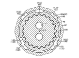
- 4 is a cross-sectional view showing a cross section taken along the line IV-IV in FIG.
- the first cylindrical inner peripheral surface 138 of the stator shaft 62 facing the outer peripheral surface of the bush 66 has a plurality of first axial grooves 140 in the circumferential direction (five in this embodiment). Is formed.
- a plurality of second axial grooves 144 (four in this embodiment) are formed in the circumferential direction on the first cylindrical outer peripheral surface 142 of the input shaft 48 facing the inner peripheral surface of the bush 66.
- the first axial groove 140 and the second axial groove 144 function as flow paths that constitute part of the open-side flow path 132. Further, the provision of the bush 66 suppresses the flow cross-sectional area of the open-side flow path 132 from being reduced by providing the first axial groove 140 and the second axial groove 144.
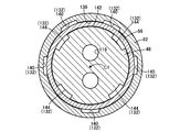
- FIG. 5 is a cross-sectional view showing a cross section taken along the line V-V in FIG.
- the second cylindrical outer peripheral surface corresponding to the spline fitting portion with the input shaft 48 of the boss portion 42 a in the first axis C ⁇ b> 1 direction.
- a plurality of third axial grooves 148 are formed in the circumferential direction 146.
- the second cylindrical inner peripheral surface 150 corresponding to the spline fitting portion (see FIG. 3) of the stator shaft 62 with the inner race 64a in the first axis C1 direction.
- a plurality of fourth axial grooves 152 are formed in the circumferential direction.
- the third axial groove 148 and the fourth axial groove 152 function as a flow path that forms part of the open-side flow path 132.
- a spline fitting portion with the input shaft 48 of the turbine 42 and a spline fitting portion with the inner race 64a of the stator shaft 62 are overlapped with each other when viewed in a direction perpendicular to the first axis C1, thereby opening the open side flow.
- a reduction in the flow cross-sectional area of the path 132 is suppressed by providing the third axial groove 148 and the fourth axial groove 152.
- a gap formed between the stator 46 and the turbine blade 44 is on the inner peripheral side of the stator 46 and the turbine blade 44 and from the through hole 132c.
- the seal member 136 is oil-tightly sealed on the outer peripheral side of the annular gap 132b located on the outer peripheral side in the radial direction.
- the seal member 136 includes an annular protrusion projecting from the sidewall portion of the inner race 64a toward the flange portion 42b of the turbine 42, and the sidewall of the inner race 64a from the flange portion 42b on the inner peripheral side of the annular projection. It is provided between the annular projection protruding toward the part side.
- the lock-up clutch 120 is engaged / released by the hydraulic control circuit 114.
- the torque capacity of the lock-up clutch 120 that can transmit power that is, the engagement force of the lock-up clutch 120 is continuously changed by adjusting the pressure of the linear solenoid valve or the like in the hydraulic control circuit 114, for example. It is done.
- the front cover 36 which is the input side rotating member of the torque converter 18, and the turbine 42, which is the output side rotating member, are directly connected. That is, when the lockup clutch 120 is engaged, the power from the engine 14 is input to the automatic transmission 18 via the front cover 36, the second damper 122, the turbine blade 44, and the turbine 42 in order.
- the released state of the lockup clutch 120 the power transmitted to the front cover 36 of the torque converter 18 is transmitted to the turbine 42 via the fluid.
- the torque converter 18 is provided with a part of an engagement-side flow path 156 through which hydraulic oil flows when the lock-up clutch 120 is engaged.
- the engagement-side flow path 156 is formed between the annular gap 156 a formed between the rear cover 38 and the stator 46, and the tubular pump drive shaft 58 and the inner race 64 a of the one-way clutch 64 and the stator shaft 62.
- the annular gap 156a and the cylindrical gap 156b communicated with the hydraulic control circuit 114, respectively.
- the cylindrical clearance 156 b of the engagement side channel 156 is communicated with the hydraulic control circuit 114 through an oil passage (not shown) formed in the stator shaft 62.
- the engagement-side flow path 156 circulates a large amount of hydraulic oil between the torque converter 18 and the hydraulic control circuit 114 that supplies the hydraulic oil to the torque converter 18 by opening the lock-up clutch 120. It has a function as a circulation return path in which a fluid is circulated from the inside of the torque converter 18 toward the hydraulic control circuit 114 during the circulation.
- the vehicle power transmission device 12 of the present embodiment includes a rear cover (input-side rotating member) 38 provided with a plurality of pump blades 40 and a turbine provided with a plurality of turbine blades 44 that receive a fluid flow from the pump blades 40.
- 18 is a vehicular power transmission device 12 provided in a power transmission path between the engine 14 and the drive wheel 16, and is divided by a partition wall 68 provided on the opposite side of the torque converter 18 from the engine 14.
- the first chamber R1 that accommodates the torque converter 18 and its partition wall 68 are formed on opposite sides of the torque converter 18.
- 58 is oil-tightly isolated from each other by an oil seal 70 that oil-tightly seals the gap between the outer peripheral surface 58 and the first side wall portion of the rear cover 38 on the partition wall 68 side and the stator 46.
- a thrust bearing 94 is disposed, and the first thrust bearing 94 is provided so as to partially overlap the oil seal 70 when viewed in a direction orthogonal to the first axis C1.
- the first thrust bearing 94 is disposed adjacent to the first thrust bearing 94 as compared with the case where the first thrust bearing 94 is not overlapped with the oil seal 70 when viewed in the direction perpendicular to the first axis C1. Since the member to be used, for example, the one-way clutch 64 is arranged close to the partition wall 68, the distance between the entire outer shell cover of the torque converter 18 that houses the first thrust bearing 94 and the one-way clutch 64 and the partition wall 68. Can be shortened. Therefore, the total axial length of the power transmission device 12 can be shortened.
- the rear cover (input-side rotating member) 38 has one radial position corresponding to the first thrust bearing 94 in the side wall portion on the partition wall 68 side.
- the first thrust bearing 94 is disposed in the annular projecting portion 38a.
- the first thrust bearing 94 is disposed in the annular projecting portion 38a. In this way, the first thrust bearing 94 and the members disposed adjacent thereto, such as the one-way clutch 64, can be disposed close to the partition wall 68 side.
- the torque converter 18 is an engine that selectively connects the crankshaft 99 of the engine 14 and the front cover (input-side rotating member) 36 of the torque converter 18.
- An intermittent clutch K0 is provided.
- the first thrust bearing 94 and the one-way clutch 64 are arranged close to the partition wall 68 side, so that the engine interrupting clutch is placed in a vacant space in the outer shell cover of the torque converter. K0 can be arranged compactly.
- the pump drive shaft (cylindrical rotating shaft) 58 disposed on the second shaft center C2 parallel to the first shaft center C1 and the tubular shaft thereof are arranged.
- An electric motor MG connected to a rear cover (input-side rotating member) 38 through an electric motor connecting rotary member 84 connected to the pump drive shaft 58 is provided, and the partition wall 68 has a part of the radial position all around the circumference.
- the motor connecting rotating member 84 is rotatably supported by the supporting portion 68b of the partition wall 68 via the second bearing 90, and protrudes toward the second chamber R2 side.
- 38 a is positioned on the inner peripheral side of the support portion 68 b of the partition wall 68.
- the output of the engine 14 is assisted by the electric motor MG, or the engine 14 is stopped and the vehicle is driven by the electric motor MG. be able to.
- the electric motor connecting rotary member 84 and the support portion 68b of the partition wall 68 for rotatably supporting the electric motor MG are provided.
- the one-thrust bearing 94 and the one-way clutch 64 can be arranged close to the partition wall 68 side.
- the vehicle is disposed on the side opposite to the engine 14 with respect to the torque converter 18 in the direction of the first axis C1, and the power from the torque converter 18 is transferred to the drive wheels 16
- the turbine 42 of the torque converter 18 is provided on the side of the automatic transmission 20 with respect to the pump blade 40 in the direction of the first axis C1 and the input shaft 48 of the automatic transmission 20 is provided.
- the stator 46 is connected to the stator shaft 62 through the one-way clutch 64 so as not to rotate relative to the stator shaft 62, and is connected to the stator shaft 62 of the inner race 64a of the one-way clutch 64 and the boss portion 42a of the turbine 42.
- the connecting portion with the input shaft 48 includes the first thrust bearing 94 and the oil as viewed in a direction orthogonal to the first axis C1. It is provided so as to overlap a part or all respectively Lumpur 70.
- the connecting portion between the boss portion 42a of the turbine 42 and the input shaft 48 and the connecting portion between the inner race 64a of the one-way clutch 64 and the stator shaft 62 are in the direction of the first axis C1. 18 outside the outer shell cover. Therefore, the length of the outer shell cover in the direction of the first axis C1 can be shortened compared to the case where each of the connecting portions is provided in the outer shell cover. The overall length can be shortened.
- the torque converter 18 includes the electric motor MG disposed on the second axis C2 parallel to the first axis C1 of the torque converter 18.
- the torque converter 18 does not necessarily include the electric motor MG. There is no need. Further, even when the torque converter 18 includes the electric motor MG, the electric motor MG does not necessarily have to be provided on the second axis C2 parallel to the first axis C1. The electric motor MG may be provided on the first axis C1.
- the torque converter 18 includes the engine intermittent clutch K0 and the lockup clutch 120.
- the torque converter 18 does not necessarily include the engine intermittent clutch K0 and the lockup clutch 120.
- the vehicle power transmission device 12 includes the automatic transmission 20 at the subsequent stage of the torque converter 18, but the automatic transmission 20 is not necessarily provided, and the turbine 42 of the torque converter 18 is not necessarily provided. And a transmission mechanism that transmits the power input to the input shaft to the subsequent stage.
- the electric motor MG rotates the input side of the torque converter 18 via the endless annular transmission chain 88 wound around the first electric motor coupling gear 82 and the second electric motor coupling gear 86.
- it is operatively connected to the rear cover 38 as a member, it may be operatively connected to the rear cover 38 via, for example, a gear pair instead of the transmission chain 88.
- the input shaft 48 of the automatic transmission 20 is rotatably supported by the stator shaft 62 via the bush 66 on the inner peripheral side of the stator shaft 62.
- the input shaft 48 is not limited to the bush 66.
- the stator shaft 62 is always non-rotated by being provided integrally with the pump cover 50.
- the stator shaft 62 is not necessarily non-rotating.
- the stator shaft 62 may be configured to be connected to the output shaft of the electric motor and rotated by the electric motor so that the capacity coefficient of the torque converter 18 can be changed, or the pump cover via a brake.
- the capacity coefficient of the torque converter 18 may be changed by being selectively switched between a rotating state and a non-rotating state by the brake.
- the vehicle power transmission device 8 is placed horizontally in front of the FF (front engine / front drive) type vehicle 6 together with the engine 14. It may be placed vertically or horizontally in other drive type vehicles such as an FR (front engine / rear drive) type vehicle or an RR (rear engine / rear drive) type vehicle.
- FF front engine / front drive
- RR rear engine / rear drive
Abstract
Description
14:エンジン
16:駆動輪
18:トルクコンバータ
20:自動変速機(伝動機構)
22:トランスアクスルケース(ケース)
38:リヤカバー(入力側回転部材)
38a:環状突出部
40:ポンプブレード
42:タービン(出力側回転部材)
44:タービンブレード
45:ステータブレード
46:ステータ
48:入力軸
58:管状ポンプ駆動軸(円筒状回転軸)
62:ステータシャフト
64:一方向クラッチ
64a:インナーレース
68:隔壁
68b:支持部
70:オイルシール
84:電動機連結用回転部材
90:第2軸受(軸受)
96:第2スラスト軸受(スラスト軸受)
99:クランク軸
K0:エンジン断続用クラッチ
MG:電動機
R1:第1室
R2:第2室
C1:第1軸心(トルクコンバータの軸心)
C2:第2軸心(第2の軸心) 12: Vehicle power transmission device 14: Engine 16: Drive wheel 18: Torque converter 20: Automatic transmission (transmission mechanism)
22: Transaxle case (case)
38: Rear cover (input side rotating member)
38a: annular protrusion 40: pump blade 42: turbine (output side rotating member)
44: Turbine blade 45: Stator blade 46: Stator 48: Input shaft 58: Tubular pump drive shaft (cylindrical rotating shaft)
62: Stator shaft 64: One-way clutch 64a: Inner race 68:
96: Second thrust bearing (thrust bearing)
99: Crankshaft K0: Engine intermittent clutch MG: Electric motor R1: First chamber R2: Second chamber C1: First shaft center (Torque converter shaft center)
C2: Second axis (second axis)
Claims (5)
- 複数のポンプブレードが設けられた入力側回転部材と該ポンプブレードからの流体流を受ける複数のタービンブレードが設けられた出力側回転部材と該ポンプブレードと該タービンブレードとの間に配設されたステータブレードが設けられたステータとを有するトルクコンバータを、エンジンと駆動輪との間の動力伝達経路に備えた車両用動力伝達装置であって、
前記トルクコンバータの前記エンジンとは反対側に設けられた隔壁により分割された、前記トルクコンバータを収容する第1室と該隔壁の該トルクコンバータとは反対側に形成された第2室とを有するケースを備え、
前記第1室と前記第2室とは、前記隔壁の内周面と、前記入力側回転部材から該第2室側へ突設された円筒状回転軸の外周面との間の隙間を油密に封止するオイルシールによって、互いに油密に隔離されており、
前記入力側回転部材の前記隔壁側の側壁部と前記ステータとの間にスラスト軸受が配設され、
該スラスト軸受は、前記トルクコンバータの軸心に直交する方向視において前記オイルシールに対して一部または全部が重なるように設けられている
ことを特徴とする車両用動力伝達装置。 An input-side rotating member provided with a plurality of pump blades, an output-side rotating member provided with a plurality of turbine blades for receiving a fluid flow from the pump blades, and the pump blades and the turbine blades. A vehicle power transmission device including a torque converter having a stator provided with a stator blade in a power transmission path between an engine and drive wheels,
A first chamber for accommodating the torque converter and a second chamber formed on the opposite side of the partition to the torque converter, which are divided by a partition provided on the opposite side of the torque converter from the engine. With a case,
The first chamber and the second chamber are oil gaps between an inner peripheral surface of the partition wall and an outer peripheral surface of a cylindrical rotary shaft that protrudes from the input-side rotating member toward the second chamber. Oil seals that are tightly sealed and isolated from each other,
A thrust bearing is disposed between the side wall portion on the partition wall side of the input side rotating member and the stator,
The thrust bearing is provided so as to partially or entirely overlap the oil seal when viewed in a direction perpendicular to the axis of the torque converter. - 前記入力側回転部材は、該入力側回転部材の前記隔壁側の側壁部のうちの、前記スラスト軸受に対応する径方向位置の一部が全周に亘って該隔壁側へ突き出されて成る環状突出部を有し、
前記スラスト軸受は、該環状突出部内に配置されている
ことを特徴とする請求項1の車両用動力伝達装置。 The input-side rotating member has an annular shape in which a part of a radial position corresponding to the thrust bearing in the side wall portion on the partition side of the input-side rotating member protrudes to the partition side over the entire circumference. Has a protrusion,
The power transmission device for a vehicle according to claim 1, wherein the thrust bearing is disposed in the annular projecting portion. - 前記トルクコンバータは、前記エンジンのクランク軸と該トルクコンバータの入力側回転部材とを選択的に連結するエンジン断続用クラッチを、前記出力側回転部材の前記エンジン側において前記入力側回転部材内に収容し、且つ前記軸心に平行な方向視において前記オイルシールおよび前記スラスト軸受に一部または全部が重なるような状態で備えていることを特徴とする請求項1または2の車両用動力伝達装置。 The torque converter houses an engine intermittent clutch for selectively connecting the crankshaft of the engine and the input side rotating member of the torque converter in the input side rotating member on the engine side of the output side rotating member. The vehicle power transmission device according to claim 1, further comprising a state in which the oil seal and the thrust bearing partially or entirely overlap when viewed in a direction parallel to the shaft center.
- 前記軸心と平行な第2の軸心上に配置され、前記円筒状回転軸と、該円筒状回転軸に連結された電動機連結用回転部材とをそれぞれ介して前記入力側回転部材に連結された電動機を備え、
前記隔壁は、径方向位置の一部が全周に亘って前記第2室側へ突き出されて成る支持部を有し、
前記電動機連結用回転部材は、軸受を介して前記隔壁の支持部により回転可能に支持されており、
前記環状突出部は、前記隔壁の支持部の内周側に位置させられていることを特徴とする請求項2または3の車両用動力伝達装置。 It is arranged on a second axis parallel to the axis, and is connected to the input side rotating member via the cylindrical rotating shaft and a motor connecting rotating member connected to the cylindrical rotating shaft. Equipped with a motor
The partition wall has a support part formed by protruding a part of the radial position over the entire circumference to the second chamber side,
The rotating member for connecting the motor is rotatably supported by a support portion of the partition wall via a bearing,
4. The vehicle power transmission device according to claim 2, wherein the annular projecting portion is positioned on an inner peripheral side of the support portion of the partition wall. - 前記軸心方向において前記トルクコンバータに対して前記エンジンとは反対側に配置され、該トルクコンバータからの動力を前記駆動輪に伝達する伝動機構を備え、
前記出力側回転部材は、前記軸心方向において前記ポンプブレードに対して前記伝動機構側で該伝動機構の入力軸に連結され、
前記ステータは、一方向クラッチを介してステータシャフトに相対回転不能に連結され、
前記一方向クラッチのインナーレースの前記ステータシャフトとの連結部分、および前記出力側回転部材の前記入力軸との連結部分は、前記軸心に直交する方向視において前記スラスト軸受および前記オイルシールに対してそれぞれ一部または全部が重なるように設けられている
ことを特徴とする請求項1乃至4のいずれか1の車両用動力伝達装置。 A power transmission mechanism that is disposed on the opposite side of the engine from the torque converter in the axial direction, and that transmits power from the torque converter to the drive wheels;
The output side rotating member is connected to the input shaft of the transmission mechanism on the transmission mechanism side with respect to the pump blade in the axial direction,
The stator is connected to a stator shaft through a one-way clutch so as not to be relatively rotatable,
The connecting portion of the inner race of the one-way clutch with the stator shaft and the connecting portion of the output-side rotating member with the input shaft are in relation to the thrust bearing and the oil seal in a direction perpendicular to the shaft center. The vehicle power transmission device according to any one of claims 1 to 4, wherein a part or all of them are provided so as to overlap each other.
Priority Applications (5)
| Application Number | Priority Date | Filing Date | Title |
|---|---|---|---|
| PCT/JP2010/070900 WO2012070118A1 (en) | 2010-11-24 | 2010-11-24 | Vehicular power transmission device |
| EP10859982.0A EP2644942B1 (en) | 2010-11-24 | 2010-11-24 | Vehicular power transmission device |
| JP2012545561A JP5472484B2 (en) | 2010-11-24 | 2010-11-24 | Power transmission device for vehicle |
| CN201080070340.1A CN103228954B (en) | 2010-11-24 | 2010-11-24 | Vehicular power transmission device |
| US13/989,332 US8974339B2 (en) | 2010-11-24 | 2010-11-24 | Vehicle power transmission device |
Applications Claiming Priority (1)
| Application Number | Priority Date | Filing Date | Title |
|---|---|---|---|
| PCT/JP2010/070900 WO2012070118A1 (en) | 2010-11-24 | 2010-11-24 | Vehicular power transmission device |
Publications (1)
| Publication Number | Publication Date |
|---|---|
| WO2012070118A1 true WO2012070118A1 (en) | 2012-05-31 |
Family
ID=46145495
Family Applications (1)
| Application Number | Title | Priority Date | Filing Date |
|---|---|---|---|
| PCT/JP2010/070900 WO2012070118A1 (en) | 2010-11-24 | 2010-11-24 | Vehicular power transmission device |
Country Status (5)
| Country | Link |
|---|---|
| US (1) | US8974339B2 (en) |
| EP (1) | EP2644942B1 (en) |
| JP (1) | JP5472484B2 (en) |
| CN (1) | CN103228954B (en) |
| WO (1) | WO2012070118A1 (en) |
Cited By (2)
| Publication number | Priority date | Publication date | Assignee | Title |
|---|---|---|---|---|
| US20160025133A1 (en) * | 2014-07-28 | 2016-01-28 | Schaeffler Technologies AG & Co. KG | Four segment contact thrust roller bearing |
| CN108561451A (en) * | 2018-05-18 | 2018-09-21 | 天津市精研工程机械传动有限公司 | A kind of clutch transmission |
Families Citing this family (26)
| Publication number | Priority date | Publication date | Assignee | Title |
|---|---|---|---|---|
| TW383508B (en) | 1996-07-29 | 2000-03-01 | Nichia Kagaku Kogyo Kk | Light emitting device and display |
| EP2644943B1 (en) * | 2010-11-24 | 2017-12-20 | Toyota Jidosha Kabushiki Kaisha | Vehicular power transmission device |
| FR3013273B1 (en) * | 2013-11-15 | 2017-03-17 | Ifp Energies Now | POWERTRAIN FOR DRIVING A MOTOR VEHICLE, ESPECIALLY FOR A HYBRID VEHICLE. |
| WO2016079118A1 (en) | 2014-11-17 | 2016-05-26 | Sadair Spear Ab | Powertrain for a vehicle |
| JP6843338B2 (en) * | 2016-07-05 | 2021-03-17 | 株式会社 神崎高級工機製作所 | HMT unit and HMT structure |
| US10630137B2 (en) | 2016-12-14 | 2020-04-21 | Bendix Commerical Vehicle Systems Llc | Front end motor-generator system and modular generator drive apparatus |
| US10543735B2 (en) | 2016-12-14 | 2020-01-28 | Bendix Commercial Vehicle Systems Llc | Hybrid commercial vehicle thermal management using dynamic heat generator |
| US10220830B2 (en) | 2016-12-14 | 2019-03-05 | Bendix Commercial Vehicle Systems | Front end motor-generator system and hybrid electric vehicle operating method |
| US10640103B2 (en) | 2016-12-14 | 2020-05-05 | Bendix Commercial Vehicle Systems Llc | Front end motor-generator system and hybrid electric vehicle operating method |
| US10532647B2 (en) | 2016-12-14 | 2020-01-14 | Bendix Commercial Vehicle Systems Llc | Front end motor-generator system and hybrid electric vehicle operating method |
| US10343677B2 (en) * | 2016-12-14 | 2019-07-09 | Bendix Commercial Vehicle Systems Llc | Front end motor-generator system and hybrid electric vehicle operating method |
| US10479180B2 (en) | 2016-12-14 | 2019-11-19 | Bendix Commercial Vehicle Systems Llc | Front end motor-generator system and hybrid electric vehicle operating method |
| US10363923B2 (en) | 2016-12-14 | 2019-07-30 | Bendix Commercial Vehicle Systems, Llc | Front end motor-generator system and hybrid electric vehicle operating method |
| US10308240B2 (en) | 2016-12-14 | 2019-06-04 | Bendix Commercial Vehicle Systems Llc | Front end motor-generator system and hybrid electric vehicle operating method |
| US10486690B2 (en) | 2016-12-14 | 2019-11-26 | Bendix Commerical Vehicle Systems, Llc | Front end motor-generator system and hybrid electric vehicle operating method |
| US11807112B2 (en) | 2016-12-14 | 2023-11-07 | Bendix Commercial Vehicle Systems Llc | Front end motor-generator system and hybrid electric vehicle operating method |
| US10166975B2 (en) * | 2016-12-22 | 2019-01-01 | GM Global Technology Operations LLC | Transmission with torque converter disconnect clutch and engine braking friction clutch |
| JP6137429B1 (en) * | 2017-01-17 | 2017-05-31 | トヨタ自動車株式会社 | Hybrid vehicle |
| DE102017203458A1 (en) * | 2017-03-02 | 2018-09-06 | Zf Friedrichshafen Ag | Gear arrangement and method for operating a gear arrangement |
| JP6531133B2 (en) * | 2017-04-27 | 2019-06-12 | 本田技研工業株式会社 | Drive device for hybrid vehicle |
| DE102018203073A1 (en) * | 2018-03-01 | 2019-09-05 | Zf Friedrichshafen Ag | Drive arrangement for a rail vehicle |
| DE102018127710A1 (en) * | 2018-11-07 | 2020-05-07 | Schaeffler Technologies AG & Co. KG | Electric drive unit and drive arrangement for an electric drive unit |
| US10844911B2 (en) * | 2019-02-06 | 2020-11-24 | Schaeffler Tehnologies AG & Co. KG | Hybrid module cooling |
| DE102019112571B4 (en) * | 2019-05-14 | 2023-05-04 | Schaeffler Technologies AG & Co. KG | Torque transfer device with dry operated disconnect clutch |
| JP7292816B2 (en) * | 2019-07-25 | 2023-06-19 | ジヤトコ株式会社 | power transmission device |
| WO2021081518A1 (en) * | 2019-10-25 | 2021-04-29 | Exedy Globalparts Corporation | Compact p2 hybrid architecture |
Citations (10)
| Publication number | Priority date | Publication date | Assignee | Title |
|---|---|---|---|---|
| JPH11125322A (en) * | 1997-10-23 | 1999-05-11 | Fuji Heavy Ind Ltd | Automatic transmission |
| JP2001355704A (en) * | 2000-04-28 | 2001-12-26 | Luk Lamellen & Kupplungsbau Beteiligungs Kg | Hydraulic torque converter |
| JP2006300135A (en) * | 2005-04-18 | 2006-11-02 | Exedy Corp | Torque converter |
| JP2007022112A (en) | 2005-07-12 | 2007-02-01 | Daihatsu Motor Co Ltd | Motor device installing structure of hybrid vehicle |
| KR100755046B1 (en) | 2006-01-06 | 2007-09-06 | 한국파워트레인 주식회사 | Torque converter for hybrid electric vehicle |
| JP2008138877A (en) | 2006-11-29 | 2008-06-19 | Luk Lamellen & Kupplungsbau Beteiligungs Kg | Piston assembly and force transmission device, particularly, force transmission device equipped with piston assembly |
| JP2009001127A (en) * | 2007-06-20 | 2009-01-08 | Toyota Motor Corp | Hybrid driving device |
| JP2009002511A (en) * | 2007-06-20 | 2009-01-08 | Luk Lamellen & Kupplungsbau Beteiligungs Kg | Hydrodynamic connecting device for hybrid vehicle |
| JP2010105450A (en) | 2008-10-28 | 2010-05-13 | Aisin Aw Co Ltd | Vehicular drive device |
| JP2010120543A (en) * | 2008-11-20 | 2010-06-03 | Toyota Motor Corp | Driving device for vehicle |
Family Cites Families (10)
| Publication number | Priority date | Publication date | Assignee | Title |
|---|---|---|---|---|
| US2727360A (en) * | 1951-11-23 | 1955-12-20 | Gen Motors Corp | Multiple rotor converter having plural impellers |
| US7077253B2 (en) * | 2002-11-16 | 2006-07-18 | Luk Lamellen Und Kupplungsbau Beteiligungs Kg | Torque converter |
| US20080142325A1 (en) | 2006-11-29 | 2008-06-19 | Luk Lamellen Und Kupplungsbau Beteiligungs Kg | Hydrodynamic torque converter |
| US7980992B2 (en) | 2006-12-11 | 2011-07-19 | Schaeffler Technologies Gmbh & Co. Kg | Multi function torque converter with turbine engine idle disconnect and method of controlling a multi function torque converter for engine idle disconnect |
| US7926635B2 (en) | 2006-12-27 | 2011-04-19 | Schaeffler Technologies Gmbh & Co. Kg | Piston assembly and a force transfer device, particularly a force transfer device with a piston assembly |
| JP4944624B2 (en) * | 2007-01-22 | 2012-06-06 | 本田技研工業株式会社 | Fluid transmission device |
| US8235191B2 (en) | 2007-06-12 | 2012-08-07 | Schaeffler Technologies AG & Co. KG | Force transfer device, a drive train with force transfer device, and a method for controlling the operation of a force transfer device in a drive train |
| US20090032351A1 (en) | 2007-07-31 | 2009-02-05 | Luk Lamellen Und Kupplungsbau Beteiligungs Kg | Combined sealing plate and leaf spring drive-plate |
| US8025136B2 (en) | 2007-08-15 | 2011-09-27 | Schaeffler Technologies GmbH $ Co. KG | Torque converter damper flange with turbine centering feature |
| US8813484B2 (en) * | 2011-01-20 | 2014-08-26 | Gm Global Technology Operations, Llc | Starting device having a throttle plate |
-
2010
- 2010-11-24 US US13/989,332 patent/US8974339B2/en not_active Expired - Fee Related
- 2010-11-24 WO PCT/JP2010/070900 patent/WO2012070118A1/en active Application Filing
- 2010-11-24 EP EP10859982.0A patent/EP2644942B1/en not_active Not-in-force
- 2010-11-24 JP JP2012545561A patent/JP5472484B2/en not_active Expired - Fee Related
- 2010-11-24 CN CN201080070340.1A patent/CN103228954B/en not_active Expired - Fee Related
Patent Citations (10)
| Publication number | Priority date | Publication date | Assignee | Title |
|---|---|---|---|---|
| JPH11125322A (en) * | 1997-10-23 | 1999-05-11 | Fuji Heavy Ind Ltd | Automatic transmission |
| JP2001355704A (en) * | 2000-04-28 | 2001-12-26 | Luk Lamellen & Kupplungsbau Beteiligungs Kg | Hydraulic torque converter |
| JP2006300135A (en) * | 2005-04-18 | 2006-11-02 | Exedy Corp | Torque converter |
| JP2007022112A (en) | 2005-07-12 | 2007-02-01 | Daihatsu Motor Co Ltd | Motor device installing structure of hybrid vehicle |
| KR100755046B1 (en) | 2006-01-06 | 2007-09-06 | 한국파워트레인 주식회사 | Torque converter for hybrid electric vehicle |
| JP2008138877A (en) | 2006-11-29 | 2008-06-19 | Luk Lamellen & Kupplungsbau Beteiligungs Kg | Piston assembly and force transmission device, particularly, force transmission device equipped with piston assembly |
| JP2009001127A (en) * | 2007-06-20 | 2009-01-08 | Toyota Motor Corp | Hybrid driving device |
| JP2009002511A (en) * | 2007-06-20 | 2009-01-08 | Luk Lamellen & Kupplungsbau Beteiligungs Kg | Hydrodynamic connecting device for hybrid vehicle |
| JP2010105450A (en) | 2008-10-28 | 2010-05-13 | Aisin Aw Co Ltd | Vehicular drive device |
| JP2010120543A (en) * | 2008-11-20 | 2010-06-03 | Toyota Motor Corp | Driving device for vehicle |
Non-Patent Citations (1)
| Title |
|---|
| See also references of EP2644942A4 |
Cited By (3)
| Publication number | Priority date | Publication date | Assignee | Title |
|---|---|---|---|---|
| US20160025133A1 (en) * | 2014-07-28 | 2016-01-28 | Schaeffler Technologies AG & Co. KG | Four segment contact thrust roller bearing |
| CN108561451A (en) * | 2018-05-18 | 2018-09-21 | 天津市精研工程机械传动有限公司 | A kind of clutch transmission |
| CN108561451B (en) * | 2018-05-18 | 2024-01-02 | 天津市精研工程机械传动有限公司 | Clutch transmission device |
Also Published As
| Publication number | Publication date |
|---|---|
| US20140256506A1 (en) | 2014-09-11 |
| EP2644942B1 (en) | 2017-05-03 |
| EP2644942A8 (en) | 2013-11-27 |
| JPWO2012070118A1 (en) | 2014-05-19 |
| EP2644942A4 (en) | 2014-09-03 |
| US8974339B2 (en) | 2015-03-10 |
| JP5472484B2 (en) | 2014-04-16 |
| CN103228954B (en) | 2015-02-25 |
| CN103228954A (en) | 2013-07-31 |
| EP2644942A1 (en) | 2013-10-02 |
Similar Documents
| Publication | Publication Date | Title |
|---|---|---|
| JP5472484B2 (en) | Power transmission device for vehicle | |
| JP5472485B2 (en) | Power transmission device for vehicle | |
| JP5472486B2 (en) | Power transmission device for vehicle | |
| JP5594369B2 (en) | Power transmission device for vehicle | |
| WO2011062265A1 (en) | Drive device for vehicle | |
| WO2011062266A1 (en) | Drive device for vehicle | |
| US9784345B2 (en) | Transmission device | |
| US7998011B2 (en) | Speed change apparatus | |
| WO2010021152A1 (en) | Automatic transmission | |
| JP6037015B2 (en) | Power transmission device | |
| US9429226B2 (en) | Automatic transmission | |
| JP2014184923A (en) | Power transmission device for vehicle | |
| JP5250013B2 (en) | Vehicle drive device | |
| WO2012018027A1 (en) | Hybrid drive device | |
| JP4230728B2 (en) | Hydraulic oil passage structure of friction element for automatic transmission | |
| JP2012240556A (en) | Driving force transmission device for hybrid vehicle | |
| JP5261461B2 (en) | Vehicle drive device | |
| JP2003278797A (en) | Speed change brake device of automatic transmission | |
| JPH0247308Y2 (en) | ||
| JP2011213231A (en) | Hybrid driving device |
Legal Events
| Date | Code | Title | Description |
|---|---|---|---|
| 121 | Ep: the epo has been informed by wipo that ep was designated in this application |
Ref document number: 10859982 Country of ref document: EP Kind code of ref document: A1 |
|
| ENP | Entry into the national phase |
Ref document number: 2012545561 Country of ref document: JP Kind code of ref document: A |
|
| NENP | Non-entry into the national phase |
Ref country code: DE |
|
| REEP | Request for entry into the european phase |
Ref document number: 2010859982 Country of ref document: EP |
|
| WWE | Wipo information: entry into national phase |
Ref document number: 2010859982 Country of ref document: EP |
|
| WWE | Wipo information: entry into national phase |
Ref document number: 13989332 Country of ref document: US |