WO2012053080A1 - 車体構造 - Google Patents
車体構造 Download PDFInfo
- Publication number
- WO2012053080A1 WO2012053080A1 PCT/JP2010/068518 JP2010068518W WO2012053080A1 WO 2012053080 A1 WO2012053080 A1 WO 2012053080A1 JP 2010068518 W JP2010068518 W JP 2010068518W WO 2012053080 A1 WO2012053080 A1 WO 2012053080A1
- Authority
- WO
- WIPO (PCT)
- Prior art keywords
- vehicle
- flange
- width direction
- roof
- panel
- Prior art date
- Legal status (The legal status is an assumption and is not a legal conclusion. Google has not performed a legal analysis and makes no representation as to the accuracy of the status listed.)
- Ceased
Links
Images


Classifications
-
- B—PERFORMING OPERATIONS; TRANSPORTING
- B62—LAND VEHICLES FOR TRAVELLING OTHERWISE THAN ON RAILS
- B62D—MOTOR VEHICLES; TRAILERS
- B62D25/00—Superstructure or monocoque structure sub-units; Parts or details thereof not otherwise provided for
- B62D25/04—Door pillars ; windshield pillars
-
- B—PERFORMING OPERATIONS; TRANSPORTING
- B62—LAND VEHICLES FOR TRAVELLING OTHERWISE THAN ON RAILS
- B62D—MOTOR VEHICLES; TRAILERS
- B62D25/00—Superstructure or monocoque structure sub-units; Parts or details thereof not otherwise provided for
- B62D25/06—Fixed roofs
Definitions
- the present invention relates to a vehicle body structure.
- Patent Document 1 discloses a vehicle front structure in which an upper portion of a front pillar is joined to a side end portion of a roof header member and a front side end portion of the roof side member via an upper joining panel.
- the flange formed at the front edge of the pillar inner panel constituting the front pillar is formed toward the outside in the vehicle width direction, and the upper part of the side inner panel forms the roof side member. Extends to a position overlapping the end of the vehicle front side.
- the cost is increased by using the upper joint panel.
- the present invention has been made in view of the above problems, and can reduce the cost of the front pillar and reduce the width of the front pillar, and can ensure the rigidity and strength of the front pillar.
- the purpose is to provide a structure.
- a vehicle body structure includes an outer flange extending inward in the vehicle width direction and a side outer panel integrally including an outer wall portion formed on the outer side of the outer flange in the vehicle width direction, An inner flange coupled to the outer flange, and an inner panel integrally including an inner wall provided facing the outer wall on the inner side in the vehicle width direction of the outer wall, and extends in the vehicle front-rear direction.
- a frame member constituting a front pillar portion and a roof side rail portion in the vehicle body, and an end portion on the outer side in the vehicle width direction is coupled to the frame member and extends in the vehicle longitudinal direction.
- the cut cross-sectional shape is a hat shape, and is combined with a roof panel constituting a roof portion of the vehicle body to form a closed cross-section with the roof panel.
- a panel, and the inner flange is formed in a portion constituting the front pillar portion and the front side of the roof side rail portion in the inner wall portion, and from the vehicle upper end portion in the inner wall portion.
- a front flange extending outward in the vehicle width direction; and a portion of the inner side wall that forms the vehicle rear side of the front side of the roof side rail portion;
- a rear flange that extends inward in the vehicle width direction from the end portion, and is formed so as to open to the vehicle upper side between the front flange and the rear flange in the inner wall portion in the vehicle width direction.
- the notch is positioned within the closed cross section as viewed from the side of the vehicle.
- the front flange formed in the front pillar portion of the inner wall portion and the front portion of the roof side rail portion is directed outward in the vehicle width direction from the vehicle upper end portion of the inner wall portion. It extends. Accordingly, since the protrusion of the front pillar portion toward the inner side in the vehicle width direction can be suppressed, the front pillar portion can be narrowed.
- the front flange is formed in the front pillar portion and the front side of the roof side rail portion in the inner wall portion, so that the vehicle width between the front flange and the rear flange in the inner wall portion.
- the notch formed between the directions is located on the vehicle rear side with respect to the front pillar portion. Therefore, since the notch is formed at a position deviated from the front pillar portion, the rigidity and strength of the front pillar portion can be ensured.
- the notch is formed in the roof side rail portion, and this notch is located in a closed cross section formed by the roof panel and the header panel in a side view of the vehicle. Therefore, by positioning the notch within the closed cross section, which is a highly rigid area, it is possible to prevent the rigidity and strength of the roof side rail portion from being lowered while securing the rigidity and strength of the front pillar portion. it can.
- the skeleton member constitutes a front pillar portion and a roof side rail portion, and the end of the header panel on the outer side in the vehicle width direction is coupled to the skeleton member. Therefore, since other members are not used for joining the front pillar portion, the roof side rail portion, and the header panel, an increase in cost can be suppressed.
- the notch is positioned on the vehicle rear side in the vehicle front-rear direction center portion or the vehicle front-rear direction center portion in the closed cross section in the vehicle side view.
- the notch is located in a region where the bending moment acting in the direction of bending the front pillar portion and the roof side rail portion in the event of a frontal collision of the vehicle is reduced. Can be further secured.
- the notch includes a pair of flanges formed at both end portions of the header panel in the vehicle front-rear direction and an outer end portion of the vehicle rear side flange and the outer flange portion of the flange on the rear side of the vehicle. And it is suitable when it adjoins to the connection part with the said rear side flange.
- the joint between the outer end of the vehicle width direction in the flange on the rear side of the vehicle and the outer flange and the rear flange is a joint between the skeleton member and the header panel, and is a highly rigid part. It is. Accordingly, when the notch is close to a portion having high rigidity in this way, it is possible to effectively compensate for the decrease in rigidity due to the notch, so that the rigidity and strength of the front pillar portion can be further ensured. it can.
- the front pillar portion can be narrowed while suppressing an increase in cost, and the rigidity and strength of the front pillar portion can be ensured.
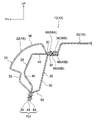
- FIG. 1 is a perspective view showing a front pillar portion, a roof side rail portion, and a roof portion in a vehicle to which a vehicle body structure according to an embodiment of the present invention is applied.
- FIG. 2 is an enlarged cross-sectional view of the front pillar portion and the periphery thereof in the vehicle shown in FIG. 1 cut along line 2-2.
- FIG. 3 is an enlarged sectional view taken along line 3-3 in FIG. 1.
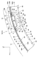
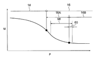
- FIG. 4 is an enlarged sectional view taken along line 4-4 of FIG. It is a figure which shows the relationship between the position of the vehicle front-back direction in a frame member, and the bending moment which acts on the direction which bends a front pillar part and a roof side rail part at the time of the front collision of a vehicle in each position.
- the arrow UP, the arrow FR, and the arrow RH shown in each figure respectively indicate the vehicle up-down direction upper side, the vehicle front-rear direction front side, and the vehicle width direction right side.
- a vehicle 12 to which a vehicle body structure 10 according to an embodiment of the present invention is applied includes a front pillar portion 14, a roof side rail portion 16, and a roof portion 18 as a part of the vehicle body.
- the front pillar portion 14 is provided along the vertical edge portion 20A of the windshield glass 20, and is inclined with respect to the vehicle front-rear direction so as to go to the vehicle upper side toward the vehicle rear side (see also FIG. 4). ).
- the roof side rail portion 16 is provided on the vehicle rear side of the front pillar portion 14 and outside the roof portion 18 in the vehicle width direction, and is formed substantially horizontally.
- the front pillar portion 14 and the roof side rail portion 16 are integrally formed by a skeleton member 22 that extends in the vehicle front-rear direction.
- the skeleton member 22 includes a plurality of panels, that is, a side outer panel 24, a pillar reinforcement 26, and an inner panel 28.
- the side outer panel 24 integrally includes an upper side wall portion 30, an outer side wall portion 32, and a lower flange 34.
- the upper side wall portion 30 extends toward the inner side in the vehicle width direction
- the outer side wall portion 32 extends from the end portion on the outer side in the vehicle width direction of the upper side wall portion 30 toward the vehicle lower side.
- the lower flange 34 extends from the vehicle lower side end portion of the outer wall portion 32 toward the vehicle width direction outer side and the vehicle lower side.
- the upper side wall portion 30 and the outer wall portion 32, which form the roof side rail portion 16 have bulge portions that bulge toward the vehicle upper side and the vehicle width direction outer side. 36 is formed.
- the edge part of the vehicle width direction inner side in the upper side wall part 30 is formed as the outer side flange 38 extended toward a vehicle width direction inner side.
- the outer flange 38 has a front portion 38A formed on the front side of the bulging portion 36 and a rear portion 38B formed on the inner side in the vehicle width direction with respect to the bulging portion 36 and the front portion 38A.
- a part 38B1 on the front side of the vehicle in the rear part 38B is located on the vehicle front side with respect to the bulging part 36, and overlaps a part 38A1 on the rear side of the vehicle in the front part 38A in the vehicle front-rear direction.
- the pillar reinforcement 26 is disposed inside the side outer panel 24, and includes an upper reinforcing portion 40, an outer reinforcing portion 42, and a lower flange 44.
- the upper reinforcing portion 40 is formed along the upper wall portion 30, and the outer reinforcing portion 42 is formed along the outer wall portion 32.
- the lower flange 44 is formed along the lower flange 34 and overlaps the lower flange 34 on the vehicle lower side.
- An end portion on the inner side in the vehicle width direction of the upper reinforcing portion 40 is formed as a flange reinforcing portion 48 extending toward the inner side in the vehicle width direction.
- the flange reinforcing portion 48 is located on the vehicle lower side of the front portion 38A of the outer flange 38. 48A and a rear portion 48B superimposed on the vehicle lower side of the rear portion 38B of the outer flange 38.
- the inner panel 28 has a lower wall portion 50, an inner wall portion 52, a lower flange 54, and an inner flange 58.
- the inner wall portion 52 is provided on the inner side in the vehicle width direction of the outer wall portion 32 so as to face the outer wall portion 32, and the lower wall portion 50 extends from the end of the inner wall portion 52 on the vehicle lower side in the vehicle width direction. It extends towards the outside.
- the lower flange 54 extends from the end of the lower wall portion 50 on the vehicle width direction outer side toward the vehicle width direction outer side and the vehicle lower side, and overlaps the lower flange 44 on the vehicle lower side.
- the inner flange 58 is formed at the vehicle upper end of the inner wall portion 52 and has a front flange 58A and a rear flange 58B.
- the front side flange 58 ⁇ / b> A is formed in a portion constituting the front pillar portion 14 and the front portion 16 ⁇ / b> A of the roof side rail portion 16 in the inner wall portion 52.
- the rear flange 58B is formed in a portion constituting the vehicle rear side portion 16B on the vehicle rear side with respect to the front portion 16A of the roof side rail portion 16 in the inner wall portion 52.
- the front flange 58 ⁇ / b> A extends from the vehicle upper end portion of the inner wall portion 52 toward the vehicle width direction outer side, and overlaps the vehicle lower side of the front portion 48 ⁇ / b> A of the flange reinforcing portion 48.
- the rear flange 58B extends inward in the vehicle width direction from the vehicle upper end portion of the inner wall portion 52, and overlaps the vehicle lower side of the rear portion 38B of the outer flange 38.
- a notch 60 is formed between the front flange 58A and the rear flange 58B in the inner wall portion 52 so as to be opened to the upper side of the vehicle.
- This notch 60 is formed to be necessary for turning back the front flange 58A in the opposite direction with respect to the rear flange 58B when the inner panel 28 is press-molded. A more detailed setting position of the notch 60 will be described later.
- the roof portion 18 includes a roof panel 62 and a header panel 64.
- the roof panel 62 is disposed on the vehicle rear side and the vehicle upper side of the windshield glass 20, and extends in the vehicle front-rear direction and the vehicle width direction.
- a flange 66 extending toward the vehicle front side is formed at an end portion of the roof panel 62 on the vehicle front side, and a flange 68 extending outward in the vehicle width direction is formed at an end portion on the vehicle width direction outer side of the roof panel 62 (see FIG. 3). ) Is formed.
- the header panel 64 extends in the vehicle width direction, is provided along the upper edge portion 20B of the windshield glass 20, and is disposed on the vehicle lower side of the front portion 62A of the roof panel 62.
- the header panel 64 has a hat shape in which a cross-sectional shape cut along the vehicle front-rear direction opens to the vehicle upper side. That is, the header panel 64 includes a bottom wall portion 70, a pair of side wall portions 72, 74 formed on both sides of the bottom wall portion 70 in the vehicle front-rear direction, and a pair of side wall portions 72, 74 formed on the vehicle upper side. Flanges 76 and 78.
- An end 76A on the outer side in the vehicle width direction of the flange 76 on the front side of the vehicle is overlapped with the lower side of the rear portion 38B of the outer flange 38, and is wider than an end 76A on the outer side in the vehicle width direction of the flange 76 on the front side of the vehicle.
- the intermediate portion 76B on the inner side in the direction is overlapped on the vehicle lower side of the flange 66.
- an end 78A on the outer side in the vehicle width direction of the flange 78 on the rear side of the vehicle is overlapped on the lower side of the vehicle on the rear side of the rear flange 58B, and an end 78A on the outer side in the vehicle width direction on the flange 78 on the rear side of the vehicle.
- the intermediate portion 78B on the inner side in the vehicle width direction overlaps the vehicle lower side of the front portion 62A of the roof panel 62.
- a flange 80 is formed at the outer end of the header panel 64 in the vehicle width direction and has a U-shape that opens to the upper side of the vehicle and extends along the inner wall portion 52.
- the flange 80 is formed integrally with the bottom wall portion 70, the pair of side wall portions 72, 74, and the pair of flanges 76, 78, and is superimposed on the inner side of the inner wall portion 52 in the vehicle width direction.
- the parts of the side outer panel 24, the pillar reinforcement 26, the inner panel 28, the roof panel 62, and the header panel 64 constituting the vehicle body structure 10 are coupled as follows.
- the front portion 38A of the outer flange 38, the front portion 48A of the flange reinforcing portion 48, and the front flange 58A are coupled by a plurality of coupling portions 82, for example, by laser welding arranged in the vehicle longitudinal direction.
- the front portion 38A of the outer flange 38, the front portion 48A of the flange reinforcing portion 48, and the front flange 58A may be joined by arc welding.
- the lower flange 34, the lower flange 44, and the lower flange 54 are coupled by a plurality of coupling portions 84, for example, spot welding arranged in the vehicle longitudinal direction (see also FIG. 4).
- the rear portion 38B of the outer flange 38, the rear portion 48B of the flange reinforcing portion 48, and the end portion 76A on the outer side in the vehicle width direction of the flange 76 on the front side of the vehicle are connected by a connecting portion 86 by spot welding, for example.
- the intermediate portion 76B on the inner side in the vehicle width direction than the end portion 76A of the flange 76 on the vehicle front side and the flange 66 are connected by a plurality of connecting portions 88, for example, by spot welding arranged in the vehicle width direction.
- the rear portion 38B of the outer flange 38, the rear portion 48B of the flange reinforcing portion 48, the rear flange 58B, and the end portion 78A on the outer side in the vehicle width direction of the flange 78 on the rear side of the vehicle are joined by a joint portion 90 by spot welding, for example. Has been.
- the end portion on the vehicle front side of the flange 68 of the roof panel 62 shown in FIG. 3 is connected to the rear portion 38 ⁇ / b> B of the outer flange 38 and the flange reinforcing portion 48 by the coupling portion 86 shown in FIG. 1.
- the rear portion 48 ⁇ / b> B is coupled to the vehicle width direction outer end portion 76 ⁇ / b> A of the vehicle front side flange 76.
- the portions corresponding to the joint portion 90 (see FIG. 1) in the flange 68 of the roof panel 62 shown in FIG. 3 are the rear portion 38B of the outer flange 38 shown in FIG.
- the rear portion 48 ⁇ / b> B, the rear flange 58 ⁇ / b> B, and the end portion 78 ⁇ / b> A on the outer side in the vehicle width direction of the vehicle rear side flange 78 are coupled.
- the vehicle rear side portion 68A on the rear side of the vehicle with respect to the coupling portion 90 (see FIG. 1) in the flange 68 of the roof panel 62, the rear portion 38B of the outer flange 38, and the rear portion of the flange reinforcing portion 48. 48B and the rear flange 58B are coupled by a plurality of coupling portions 92, for example, by spot welding arranged in the vehicle longitudinal direction (see also FIG. 1). Further, as shown in FIG.
- an intermediate portion 78 ⁇ / b> B on the vehicle width direction inner side of the end portion 78 ⁇ / b> A on the vehicle width direction outer side of the flange 78 on the vehicle rear side and a front portion 62 ⁇ / b> A of the roof panel 62 are It is glued. Further, the inner wall portion 52 and the flange 80 are coupled by a plurality of coupling portions 96 formed by spot welding, for example, arranged along the U-shape of the flange 80.
- the skeleton member 22 is formed in a closed cross-sectional shape by connecting the side outer panel 24, the pillar reinforcement 26, and the inner panel 28 to each other.
- the outer wall portion 32 and the inner wall portion 52 extend to the front seat side (arrow A side) (not shown).
- skeleton member 22 sees from the extending direction rather than the vertical width W1 along the direction where the above-mentioned outer side wall part 32 and the inner side wall part 52 are extended to the front seat side which is not shown in figure.
- the horizontal width W2 is narrower.
- the header panel 64 is coupled to the front portion 62 ⁇ / b> A of the roof panel 62 to reinforce the front portion 62 ⁇ / b> A of the roof panel 62, and forms a closed section 98 with the roof panel 62. is doing. That is, the closed section 98 is more specifically formed by the bottom wall portion 70 and the pair of side wall portions 72 and 74 formed on the header panel 64 and the front portion 62A of the roof panel 62.
- a notch formed between the front flange 58A and the rear flange 58B in the vehicle width direction is positioned above the front pillar portion 14.
- the rigidity and strength at the upper part of the front pillar 14 may be reduced.
- a measure such as providing a reinforcing member is taken separately, the cost increases.
- the following configuration is adopted. That is, the front flange 58A is extended until the rear end portion 58A1 overlaps the front portion 16A of the roof side rail portion 16 in the vehicle front-rear direction, and the notch 60 is formed on the front portion 16A of the roof side rail portion 16.
- the notch 60 is located on the vehicle rear side with respect to the vehicle front-rear direction center in the closed section 98 in a side view of the vehicle, and more specifically, close to the coupling portion 90. It is located in the rear part in the closed cross section 98 in the vehicle side view.
- the notch 60 is set at a position away from the front pillar portion 14, and is positioned within the closed cross-section 98 that is a highly rigid region.
- the windshield glass 20 is arranged so that the vertical edge 20 ⁇ / b> A on the outer side in the vehicle width direction overlaps the front side of the outer flange 38.
- the vertical edge portion 20 ⁇ / b> A of the windshield glass 20 is fixed to the outer flange 38 with an adhesive 100.
- the lower flange 34, the lower flange 44, and the lower flange 54 constitute an attachment portion 102, and an opening weather strip 104 is attached to the attachment portion 102.
- an outer molding 106 is disposed outside the windshield glass 20 in the vehicle width direction.
- the outer molding 106 is attached to the skeleton member 22 via a bracket or the like (not shown).
- An inner garnish 108 is provided on the vehicle inner side of the front pillar portion 14.
- the side door 110 is provided with a side glass 112 and a door frame 114 that supports the side glass 112 so as to be movable up and down, and a door weather strip 116 is attached to the door frame 114.
- the front pillar portion 14 and the front portion 16 ⁇ / b> A of the roof side rail portion 16 are formed on the inner wall portion 52.
- the front flange 58A extends from the vehicle upper end portion of the inner wall portion 52 toward the vehicle width direction outer side. Therefore, since the protrusion of the front pillar portion 14 to the inner side in the vehicle width direction can be suppressed, the front pillar portion 14 can be narrowed. Thereby, the field of view from the driver's seat can be expanded.
- the front flange 58A is formed in the portion constituting the front pillar portion 14 and the front portion 16A of the roof side rail portion 16 in the inner wall portion 52, so that the front flange 58A in the inner wall portion 52 and The notch 60 formed between the rear flange 58B and the vehicle width direction is located on the vehicle rear side with respect to the front pillar portion 14. Therefore, since the notch 60 is formed at a position away from the front pillar portion 14, the rigidity and strength of the front pillar portion 14 can be ensured.
- the notch 60 is formed in the roof side rail portion 16, but the notch 60 is in a closed cross section 98 formed by the front portion 62 ⁇ / b> A of the roof panel 62 and the header panel 64 in a vehicle side view. Is located. Therefore, the notch 60 is positioned in the closed section 98, which is a highly rigid region, so that the rigidity and strength of the roof side rail portion 16 may be reduced while ensuring the rigidity and strength of the front pillar portion 14. Can be suppressed.
- the skeleton member 22 constitutes the front pillar portion 14 and the roof side rail portion 16, and the outer end portion of the header panel 64 in the vehicle width direction is the inner wall portion 52 of the inner panel 28 constituting the skeleton member 22. Is bound to. Accordingly, since no other member is used for joining the front pillar portion 14, the roof side rail portion 16, and the header panel 64, it is possible to suppress an increase in cost.
- the notch 60 is located at the rear portion in the closed section 98 in a vehicle side view.
- the bending moment acting in the direction of bending the front pillar portion 14 and the roof side rail portion 16 at the time of a frontal collision of the vehicle has the following characteristics.
- FIG. 5 acts in a direction in which the front pillar portion 14 and the roof side rail portion 16 are bent at the vehicle front-rear direction position P in the skeleton member 22 shown in FIG.
- the relationship with the bending moment M is shown.
- the bending moment M gradually decreases as the roof side rail portion 16 is approached.
- the bending moment M gradually decreases toward the vehicle rear side, and in the rear side portion 16B of the roof side rail portion 16, the rear side portion 16B is substantially horizontal. Therefore, the bending moment M becomes substantially constant at a value reduced as compared with the case of the front pillar portion 14. Therefore, as described above, when the notch 60 is located at the rear portion in the closed cross section 98 in the vehicle side view, the notch 60 is located in the region where the bending moment is reduced. Rigidity and strength can be further ensured.
- the notch 60 is a connecting portion 90 between an end portion 78 ⁇ / b> A of the vehicle rear side flange 78 in the vehicle width direction, the rear portion 38 ⁇ / b> B of the outer flange 38, and the rear flange 58 ⁇ / b> B.
- the coupling portion 92 is a coupling portion between the skeleton member 22 and the header panel 64, and is a highly rigid portion. Therefore, if the notch 60 is close to a portion having high rigidity in this way, it is possible to effectively compensate for the decrease in rigidity due to the notch 60, so that the rigidity and strength of the front pillar portion 14 are further secured. can do.
- the notch 60 is positioned at the rear portion in the closed cross section 98 when viewed from the side of the vehicle.
- the notch 60 is viewed from the side of the vehicle.
- the vehicle In the closed cross section 98, the vehicle may be positioned on the vehicle front side with respect to the vehicle front-rear direction center or the vehicle front-rear direction center.
Landscapes
- Engineering & Computer Science (AREA)
- Chemical & Material Sciences (AREA)
- Combustion & Propulsion (AREA)
- Transportation (AREA)
- Mechanical Engineering (AREA)
- Body Structure For Vehicles (AREA)
Abstract
Description
Claims (3)
- 車両幅方向内側に向けて延びる外側フランジ及び前記外側フランジの車両幅方向外側に形成された外側壁部を一体に有するサイドアウタパネルと、前記外側フランジと結合された内側フランジ及び前記外側壁部の車両幅方向内側に前記外側壁部と対向して設けられた内側壁部を一体に有するインナパネルとを有すると共に、車両前後方向に延在され、車体におけるフロントピラー部及びルーフサイドレール部を構成する骨格部材と、
車両幅方向に延在され、車両幅方向外側の端部が前記骨格部材に結合されると共に、車両前後方向に沿って切断した断面形状がハット状とされ、且つ、車体におけるルーフ部を構成するルーフパネルに結合されて前記ルーフパネルとで閉断面を構成するヘッダパネルと、
を備え、
前記内側フランジは、前記内側壁部における前記フロントピラー部及び前記ルーフサイドレール部の前部を構成する部分に形成されると共に、前記内側壁部における車両上側の端部から車両幅方向外側に向けて延びる前側フランジと、前記内側壁部における前記ルーフサイドレール部の前記前部よりも車両後側部を構成する部分に形成されると共に、前記内側壁部の車両上側の端部から車両幅方向内側に向けて延びる後側フランジと、を有し、
前記内側壁部における前記前側フランジと前記後側フランジとの車両幅方向間に車両上側に開口するように形成された切欠きは、車両側面視にて前記閉断面内に位置されている、
車体構造。 - 前記切欠きは、車両側面視にて前記閉断面内における車両前後方向中央部又は車両前後方向中央部よりも車両後側に位置されている、
請求項1に記載の車体構造。 - 前記ヘッダパネルにおける車両前後方向両側の端部に形成された一対のフランジのうち車両後側のフランジは、車両幅方向外側の端部が前記外側フランジ及び前記後側フランジと結合され、
前記切欠きは、前記一対のフランジのうち車両後側のフランジにおける車両幅方向外側の端部と前記外側フランジ及び前記後側フランジとの結合部に近接されている、
請求項1又は請求項2に記載の車体構造。
Priority Applications (5)
| Application Number | Priority Date | Filing Date | Title |
|---|---|---|---|
| CN201080059868.9A CN102686474B (zh) | 2010-10-20 | 2010-10-20 | 车身结构 |
| EP10858636.3A EP2631158A1 (en) | 2010-10-20 | 2010-10-20 | Vehicle body structure |
| PCT/JP2010/068518 WO2012053080A1 (ja) | 2010-10-20 | 2010-10-20 | 車体構造 |
| US13/643,743 US20130193716A1 (en) | 2010-10-20 | 2010-10-20 | Vehicle body structure |
| JP2011552263A JP5141834B2 (ja) | 2010-10-20 | 2010-10-20 | 車体構造 |
Applications Claiming Priority (1)
| Application Number | Priority Date | Filing Date | Title |
|---|---|---|---|
| PCT/JP2010/068518 WO2012053080A1 (ja) | 2010-10-20 | 2010-10-20 | 車体構造 |
Publications (1)
| Publication Number | Publication Date |
|---|---|
| WO2012053080A1 true WO2012053080A1 (ja) | 2012-04-26 |
Family
ID=45974816
Family Applications (1)
| Application Number | Title | Priority Date | Filing Date |
|---|---|---|---|
| PCT/JP2010/068518 Ceased WO2012053080A1 (ja) | 2010-10-20 | 2010-10-20 | 車体構造 |
Country Status (5)
| Country | Link |
|---|---|
| US (1) | US20130193716A1 (ja) |
| EP (1) | EP2631158A1 (ja) |
| JP (1) | JP5141834B2 (ja) |
| CN (1) | CN102686474B (ja) |
| WO (1) | WO2012053080A1 (ja) |
Cited By (5)
| Publication number | Priority date | Publication date | Assignee | Title |
|---|---|---|---|---|
| JP2014113980A (ja) * | 2012-12-12 | 2014-06-26 | Suzuki Motor Corp | 車両のフロントピラー上部構造 |
| WO2016080193A1 (ja) * | 2014-11-17 | 2016-05-26 | 豊田鉄工株式会社 | 車両用フロントピラー |
| JP2016159786A (ja) * | 2015-03-02 | 2016-09-05 | 豊田鉄工株式会社 | 車両用フロントピラー |
| JP2020006859A (ja) * | 2018-07-10 | 2020-01-16 | スズキ株式会社 | 車両用フロントピラーの周辺構造 |
| CN111169540A (zh) * | 2018-11-13 | 2020-05-19 | 丰田自动车株式会社 | 车辆用支柱构造 |
Families Citing this family (19)
| Publication number | Priority date | Publication date | Assignee | Title |
|---|---|---|---|---|
| DE102011120519A1 (de) * | 2011-12-08 | 2013-06-13 | GM Global Technology Operations LLC (n. d. Gesetzen des Staates Delaware) | Verstärkung für eine Fahrzeugsäule, insbesodnere die B-Säule eines Fahrzeuges |
| JP5926089B2 (ja) * | 2012-03-29 | 2016-05-25 | 東プレ株式会社 | プレス成形品 |
| JP2015123811A (ja) * | 2013-12-25 | 2015-07-06 | トヨタ自動車株式会社 | 車両骨格構造 |
| US9505447B2 (en) | 2014-06-27 | 2016-11-29 | Ford Global Technologies, Llc | Gap joint for closed section load transfer |
| US9302710B2 (en) | 2014-08-07 | 2016-04-05 | Honda Motor Co., Ltd. | Front pillar attachment for a vehicle body |
| US9481320B2 (en) | 2014-08-07 | 2016-11-01 | Honda Motor Co., Ltd. | Front pillar exterior garnish for a vehicle body |
| DE102015100263B3 (de) * | 2015-01-09 | 2016-03-31 | Audi Ag | Strukturbauteil für eine Karosserie eines Personenkraftwagens |
| DE102015106812B4 (de) * | 2015-04-30 | 2018-11-08 | Benteler Automobiltechnik Gmbh | Kraftfahrzeugsäule mit Verstärkungsblech sowie Verfahren zu dessen Herstellung |
| JP6269613B2 (ja) * | 2015-08-05 | 2018-01-31 | トヨタ自動車株式会社 | 車体骨格構造及びその製造方法 |
| JP6236046B2 (ja) * | 2015-09-17 | 2017-11-22 | 本田技研工業株式会社 | 車体構造 |
| ES2566036B2 (es) * | 2015-12-23 | 2016-09-20 | Seat, S.A. | Sistema y procedimiento de ensamblaje entre subconjuntos de una carrocería de un vehículo |
| JP6575015B2 (ja) * | 2017-07-07 | 2019-09-18 | 本田技研工業株式会社 | 車体構造 |
| EP3434565B1 (en) * | 2017-07-26 | 2021-01-20 | Toyota Jidosha Kabushiki Kaisha | Vehicle side section structure |
| EP3486149B1 (en) * | 2017-11-21 | 2020-08-12 | Ningbo Geely Automobile Research & Development Co., Ltd. | A front header structure and a vehicle comprising a front header structure |
| JP6969429B2 (ja) * | 2018-02-20 | 2021-11-24 | トヨタ自動車株式会社 | 車両側部構造 |
| JP7074021B2 (ja) * | 2018-10-26 | 2022-05-24 | トヨタ自動車株式会社 | 車両用ピラー構造 |
| KR102575185B1 (ko) * | 2018-12-10 | 2023-09-05 | 현대자동차 주식회사 | 차체 구조 |
| JP7834537B2 (ja) * | 2022-03-31 | 2026-03-24 | 本田技研工業株式会社 | 車体上部構造及び自動車車体の組立方法 |
| JP7590392B2 (ja) * | 2022-11-04 | 2024-11-26 | フタバ産業株式会社 | フロントピラーロア |
Citations (3)
| Publication number | Priority date | Publication date | Assignee | Title |
|---|---|---|---|---|
| JPH0124668B2 (ja) * | 1985-03-20 | 1989-05-12 | Daihatsu Motor Co Ltd | |
| WO2006038430A1 (ja) | 2004-09-30 | 2006-04-13 | Hino Motors, Ltd. | 車両用前部構造 |
| JP2007030780A (ja) | 2005-07-29 | 2007-02-08 | Hino Motors Ltd | 車両の前部構造 |
Family Cites Families (7)
| Publication number | Priority date | Publication date | Assignee | Title |
|---|---|---|---|---|
| US6139094A (en) * | 1998-05-04 | 2000-10-31 | Aluminum Company Of America | Rocker to pillar joint |
| JP4696756B2 (ja) * | 2005-07-27 | 2011-06-08 | マツダ株式会社 | 自動車の上部車体構造 |
| FR2921038B1 (fr) * | 2007-09-19 | 2010-01-01 | Peugeot Citroen Automobiles Sa | Structure de carrosserie de vehicule a jonction renforcee entre la traverse avant de pavillon et la doublure du montant de baie de pare-brise |
| JP5003424B2 (ja) * | 2007-11-19 | 2012-08-15 | トヨタ車体株式会社 | 自動車のルーフ構造 |
| JP2009255800A (ja) * | 2008-04-18 | 2009-11-05 | Toyota Motor Corp | 車両用骨格部材の結合構造 |
| JP5223573B2 (ja) * | 2008-09-30 | 2013-06-26 | マツダ株式会社 | 自動車のルーフ部構造 |
| JP2010115961A (ja) * | 2008-11-11 | 2010-05-27 | Toyota Motor Corp | 車体の骨格構造 |
-
2010
- 2010-10-20 JP JP2011552263A patent/JP5141834B2/ja not_active Expired - Fee Related
- 2010-10-20 CN CN201080059868.9A patent/CN102686474B/zh not_active Expired - Fee Related
- 2010-10-20 WO PCT/JP2010/068518 patent/WO2012053080A1/ja not_active Ceased
- 2010-10-20 EP EP10858636.3A patent/EP2631158A1/en not_active Withdrawn
- 2010-10-20 US US13/643,743 patent/US20130193716A1/en not_active Abandoned
Patent Citations (3)
| Publication number | Priority date | Publication date | Assignee | Title |
|---|---|---|---|---|
| JPH0124668B2 (ja) * | 1985-03-20 | 1989-05-12 | Daihatsu Motor Co Ltd | |
| WO2006038430A1 (ja) | 2004-09-30 | 2006-04-13 | Hino Motors, Ltd. | 車両用前部構造 |
| JP2007030780A (ja) | 2005-07-29 | 2007-02-08 | Hino Motors Ltd | 車両の前部構造 |
Cited By (9)
| Publication number | Priority date | Publication date | Assignee | Title |
|---|---|---|---|---|
| JP2014113980A (ja) * | 2012-12-12 | 2014-06-26 | Suzuki Motor Corp | 車両のフロントピラー上部構造 |
| WO2016080193A1 (ja) * | 2014-11-17 | 2016-05-26 | 豊田鉄工株式会社 | 車両用フロントピラー |
| JP2016094177A (ja) * | 2014-11-17 | 2016-05-26 | 豊田鉄工株式会社 | 車両用フロントピラー |
| JP2016159786A (ja) * | 2015-03-02 | 2016-09-05 | 豊田鉄工株式会社 | 車両用フロントピラー |
| WO2016139866A1 (ja) * | 2015-03-02 | 2016-09-09 | 豊田鉄工株式会社 | 車両用フロントピラー |
| JP2020006859A (ja) * | 2018-07-10 | 2020-01-16 | スズキ株式会社 | 車両用フロントピラーの周辺構造 |
| FR3083768A1 (fr) * | 2018-07-10 | 2020-01-17 | Suzuki Motor Corporation | Structure peripherique de montant avant de vehicule |
| JP7172205B2 (ja) | 2018-07-10 | 2022-11-16 | スズキ株式会社 | 車両用フロントピラーの周辺構造 |
| CN111169540A (zh) * | 2018-11-13 | 2020-05-19 | 丰田自动车株式会社 | 车辆用支柱构造 |
Also Published As
| Publication number | Publication date |
|---|---|
| JP5141834B2 (ja) | 2013-02-13 |
| EP2631158A1 (en) | 2013-08-28 |
| CN102686474A (zh) | 2012-09-19 |
| JPWO2012053080A1 (ja) | 2014-02-24 |
| US20130193716A1 (en) | 2013-08-01 |
| CN102686474B (zh) | 2013-08-21 |
Similar Documents
| Publication | Publication Date | Title |
|---|---|---|
| JP5141834B2 (ja) | 車体構造 | |
| CN105882760B (zh) | 车辆的上部车身结构 | |
| JP5088570B2 (ja) | 車両のセンターピラー構造 | |
| EP2412612B1 (en) | Side sill structure for automobile | |
| JP6032550B2 (ja) | 車両のフロントピラー上部構造 | |
| JP2014125040A (ja) | 車両の上部車体構造 | |
| JP4996707B2 (ja) | 自動車の車体側部構造 | |
| JP5871133B2 (ja) | 車両の後部車体構造 | |
| CN100575653C (zh) | 开口部分结构 | |
| JP2019034643A (ja) | 車体上部構造 | |
| JP6074815B2 (ja) | 自動車の車体構造 | |
| JP4894629B2 (ja) | 自動車のロッカー補強構造 | |
| JP2010143453A (ja) | 車両のドア構造 | |
| JP6229675B2 (ja) | 車両の上部車体構造 | |
| JP2014069632A (ja) | 自動車のピラー補強構造 | |
| JP2013001245A (ja) | ルーフパネル接合構造 | |
| JP6237669B2 (ja) | 車両の上部車体構造 | |
| JP5549866B2 (ja) | 車両の下部構造 | |
| JP6073280B2 (ja) | 車体上部構造 | |
| JP6502981B2 (ja) | 車体後部構造 | |
| JP6237670B2 (ja) | 車両の上部車体構造 | |
| JP4666254B2 (ja) | キャブオーバ型車両の乗降口周縁部構造 | |
| JP2004010013A (ja) | 車両用ドア | |
| KR101427957B1 (ko) | 차량의 필러구조 | |
| JP5577215B2 (ja) | 自動車のロアバック構造 |
Legal Events
| Date | Code | Title | Description |
|---|---|---|---|
| WWE | Wipo information: entry into national phase |
Ref document number: 201080059868.9 Country of ref document: CN |
|
| WWE | Wipo information: entry into national phase |
Ref document number: 2011552263 Country of ref document: JP |
|
| 121 | Ep: the epo has been informed by wipo that ep was designated in this application |
Ref document number: 10858636 Country of ref document: EP Kind code of ref document: A1 |
|
| WWE | Wipo information: entry into national phase |
Ref document number: 13643743 Country of ref document: US |
|
| WWE | Wipo information: entry into national phase |
Ref document number: 2010858636 Country of ref document: EP |
|
| NENP | Non-entry into the national phase |
Ref country code: DE |