WO2012046643A1 - 風洞試験用模型および風洞試験方法 - Google Patents
風洞試験用模型および風洞試験方法 Download PDFInfo
- Publication number
- WO2012046643A1 WO2012046643A1 PCT/JP2011/072518 JP2011072518W WO2012046643A1 WO 2012046643 A1 WO2012046643 A1 WO 2012046643A1 JP 2011072518 W JP2011072518 W JP 2011072518W WO 2012046643 A1 WO2012046643 A1 WO 2012046643A1
- Authority
- WO
- WIPO (PCT)
- Prior art keywords
- wind tunnel
- tunnel test
- torsional rigidity
- machine model
- model
- Prior art date
- Legal status (The legal status is an assumption and is not a legal conclusion. Google has not performed a legal analysis and makes no representation as to the accuracy of the status listed.)
- Ceased
Links
Images



Classifications
-
- G—PHYSICS
- G01—MEASURING; TESTING
- G01M—TESTING STATIC OR DYNAMIC BALANCE OF MACHINES OR STRUCTURES; TESTING OF STRUCTURES OR APPARATUS, NOT OTHERWISE PROVIDED FOR
- G01M9/00—Aerodynamic testing; Arrangements in or on wind tunnels
- G01M9/02—Wind tunnels
- G01M9/04—Details
-
- G—PHYSICS
- G01—MEASURING; TESTING
- G01M—TESTING STATIC OR DYNAMIC BALANCE OF MACHINES OR STRUCTURES; TESTING OF STRUCTURES OR APPARATUS, NOT OTHERWISE PROVIDED FOR
- G01M9/00—Aerodynamic testing; Arrangements in or on wind tunnels
- G01M9/08—Aerodynamic models
-
- G—PHYSICS
- G01—MEASURING; TESTING
- G01M—TESTING STATIC OR DYNAMIC BALANCE OF MACHINES OR STRUCTURES; TESTING OF STRUCTURES OR APPARATUS, NOT OTHERWISE PROVIDED FOR
- G01M9/00—Aerodynamic testing; Arrangements in or on wind tunnels
- G01M9/06—Measuring arrangements specially adapted for aerodynamic testing
- G01M9/062—Wind tunnel balances; Holding devices combined with measuring arrangements
Definitions
- the present invention relates to a wind tunnel test model and a wind tunnel test method.
- an anti-symmetric mode flutter phenomenon When an aircraft flies in a subsonic or transonic region, an anti-symmetric mode flutter phenomenon may occur.
- This anti-symmetric mode flutter phenomenon is a flutter phenomenon in which the left and right wings of an aircraft are accompanied by vibrations in opposite phases (that is, an anti-symmetric mode). Therefore, a wind tunnel test using an aircraft model is performed before flight or for accuracy verification of aeroelastic analysis.
- Wind tunnel test models used for wind tunnel testing of such an anti-symmetric mode flutter phenomenon include a full aircraft model that simulates the fuselage and both wings, and a half aircraft model that simulates the fuselage and one wing of the aircraft. is there.
- an inversely symmetric aerodynamic force applied to the left and right wings can be simulated (see FIG. 3 (a) of Patent Document 1), which is advantageous in that the inversely symmetric mode flutter phenomenon can be reproduced. It is.
- a half-machine model that can be installed in a relatively small wind tunnel test apparatus and can be expected to improve accuracy by increasing the scale of one wing compared to the full-machine model is attracting attention.
- the half machine model is installed in the wind tunnel using a support device that simulates the degree of freedom of roll of the machine body. There is a way to install on the wall.
- the vibration characteristic can simulate the inverse symmetry, as shown in FIG.
- Patent Document 1 proposes a method in which the pivot point of the half-machine model is positioned away from the wind tunnel wall. As a result, the influence of the wind tunnel wall can be eliminated, and as shown in FIG. 3B of Patent Document 1, the asymmetrical aerodynamic force can be reproduced with the aerodynamic force being zero at the pivot point.
- Patent Document 1 As shown in FIG. 1 (b), the half-machine model is supported by a support from below. In this case, the support becomes resistance, and there is a risk of disturbing the wind conditions of the half model. In addition, additional work such as making a hole in the lower part of the wind tunnel wall is required to install the support, and a lot of time and cost are required for setting up the wind tunnel test.
- An object of the present invention is to provide a wind tunnel test model and a wind tunnel test method capable of realizing a wind tunnel test of a mode flutter phenomenon with high accuracy.
- the wind tunnel test model and the wind tunnel test method of the present invention employ the following means. That is, the wind tunnel test model according to the first aspect of the present invention includes a half machine model part simulating the fuselage and one wing of the fuselage, and a position spaced from the wind tunnel wall around the half machine model part about the central axis.
- a wind tunnel test model including a support device rotatably supported on the wind tunnel, the support device having a cross-sectional shape substantially the same as or similar to the body portion and extending rearward.
- a fixing portion for fixing the half-machine model part on the wind tunnel testing apparatus side is provided on the rear end side, and a torsional rigidity imparting means for giving a predetermined torsional rigidity around the central axis to the half-machine model part is provided. It is provided in the body.
- the support device By separating the support device that supports the semi-machine model part so as to be rotatable around the central axis from the wind tunnel wall, it is possible to accurately reproduce the anti-symmetric mode flutter phenomenon by simulating not only vibration characteristics but also aerodynamic force. it can.
- the support device has a cross-sectional shape that is substantially the same as or similar to that of the body portion and extends rearward, so that the support device has a semi-machine model portion located on the front side (fluid flow upstream side). There is no hindrance to the wind conditions. Furthermore, since the fixing part for fixing the half machine model part to the wind tunnel test apparatus side is provided on the rear end side of the support device, the wind condition is not inhibited against the half machine model part.
- the support device includes a torsional rigidity imparting means for giving a predetermined torsional rigidity around the central axis to the half machine model part, a counter torque against a moment in the roll direction of the half machine model part caused by aerodynamic force is provided. Can be given. Furthermore, since the torsional rigidity imparting means is housed in the housing of the support device, the torsional rigidity imparting means does not disturb the wind conditions. As the torsional rigidity imparting means, a torque shaft such as a round bar is typically used, and a coil spring or the like can also be used.
- the torsional rigidity of the torsional rigidity imparting means it is preferable to select a torsional rigidity that generates a counter torque when the half-machine model portion generates a steady lift.
- the torsional rigidity is adjusted by changing the cross-sectional shape of the torque shaft to change the polar section coefficient.
- the fixing portion may be configured to fix the support device to a sting pod provided in the wind tunnel test device.
- the equipment of the existing test apparatus can be used, and the wind tunnel test can be performed without generating additional work and additional costs. Also, if the sting pod axis and the center axis of the half-machine model part are fixed and offset so as to be substantially parallel, after the wind tunnel test model is fixed to the sting pod, the torsional rigidity imparting means is supported by the support device. Can be inserted / removed from the rear of the wind tunnel, which facilitates wind tunnel testing.
- the torsional rigidity of the torsional rigidity imparting means is 1/3 or less, preferably 1/5 or less of the primary natural frequency of the half-machine model part.
- the configuration may be such that the torsional rigidity imparting means has the primary natural frequency.
- the torsional rigidity of the half-machine model is sufficient if the torsional rigidity of the half-machine model is sufficient to generate a counter-torque at the time of steady lift generation. It is not preferable for grasping (especially the antisymmetric mode flutter phenomenon). Accordingly, the torsional rigidity is preferably set so that the torsional rigidity imparting means has a primary natural frequency of 1/3 or less, preferably 1/5 or less of the primary natural frequency of the semi-machine model part. is there.
- the torsional rigidity imparting means is a rod-shaped torque shaft, and the torque shaft has a front end fixed to the body portion side.
- the rear end side may be fixed at a predetermined fixing position with respect to the housing of the support device, and the fixing position may be changeable in the longitudinal direction of the torque shaft. .
- the wind tunnel test method according to the second aspect of the present invention is characterized in that the above-described wind tunnel test model is attached to a wind tunnel test apparatus and an inverse symmetric mode flutter wind tunnel test is performed.
- the anti-symmetric mode flutter phenomenon can be realized with high accuracy.
- the support device provided behind the half machine model part By supporting the half machine model part by the support device provided behind the half machine model part, it is possible to support without disturbing the wind conditions around the half machine model part.
- the wind tunnel test model away from the wind tunnel wall and supporting the half-machine model part with a torque shaft that gives an appropriate counter torque against the steady lift, the wind tunnel of the anti-symmetric mode flutter phenomenon The test can be realized with high accuracy.
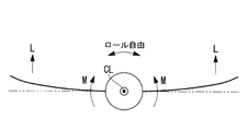
- FIG. 2 is a partial cross-sectional plan view of the wind tunnel test model of FIG. 1. It is the figure which showed the moment M which arises in a model when the steady lift L acts with respect to the whole machine model. It is the figure which showed the moment M which arises in a model when the steady lift L acts with respect to a half-machine model.
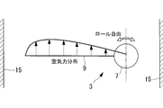
- the aerodynamic force distribution in the case of using a half-machine model is shown, and the case where the half-machine model is installed on the wind tunnel wall in a rotatable (rollable) manner.
- the aerodynamic force distribution in the case of using a half-machine model is shown, and the case where the half-machine model is installed at a position distant from the wind tunnel wall so as to be rotatable (rollable).
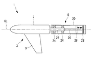
- FIG. 1 shows a wind tunnel test model 1 used for a wind tunnel test of an inversely symmetric mode flutter phenomenon.
- the model 1 has a half machine model part 3 that simulates the fuselage and one wing of the machine body, and a support device 5 that supports the half machine model part 3 so as to be rotatable about the central axis CL (roll freely).
- the half-machine model part 3 includes a body part 7 simulating the front part of the body fuselage, and a wing 9 simulating one wing of the body.
- drum 7 is made into the tapered cylindrical shape.
- the body portion 7 does not have a halved shape that is divided into two by a vertical plane including the central axis. This is because maintaining the cylindrical shape as shown in FIG. 1 does not disturb the air flow and contributes to improvement in measurement accuracy. Therefore, in this embodiment, the mass is adjusted so that the moment of inertia of the body portion 7 is 1 ⁇ 2 that of the entire model.
- the supporting device 5 is connected to the rear end (downstream side of the air flow) of the body portion 7, and the outer cross-sectional shape is substantially the same as the cross-sectional shape at the rear end of the body portion 7. Yes.
- the support device 5 includes a fixing portion 11 for fixing the half machine model portion 3 to the wind tunnel testing device side on the rear end side.
- the fixing part 11 is attached so as to stand up from the tip of a sting pod 13 already installed in the wind tunnel test apparatus.
- the sting pod 13 is originally for rigidly fixing the model to the tip thereof via sting.
- the sting pod 13 is used to fix the half machine model portion 3 so as to be rotatable.
- the axis of the sting pod 13 and the central axis of the half machine model unit 3 are installed so as to be substantially parallel. Further, the fixed portion 11 is erected from the sting pod 13, thereby offsetting the axis of the sting pod 13 and the central axis of the half machine model portion 3. By offsetting in this way, after fixing the wind tunnel test model 1 to the sting pod 13, a torque shaft 26 (see FIG. 2), which will be described later, can be inserted / removed from the rear of the support device 5, and the work of the wind tunnel test is performed. Becomes easier.
- FIG. 4A shows a case where the half-machine model is installed on the wind tunnel wall 15 so as to be rotatable (rollable) as a reference example.
- the aerodynamic distribution at the center of rotation of the half-machine model is not zero, and the aerodynamic distribution cannot be made asymmetric.
- FIG. 2 shows the internal structure of the support device 5 that supports the half machine model portion 3.
- a rotation shaft 22 fixed to the rear end of the body portion 7 is inserted into the housing 20 of the support device 5.
- the rotation shaft 22 extends along the central axis CL from the rear end of the body portion 7 to the rear (right side in the drawing).
- a pair of radial bearings 24, 24 that rotatably support the rotating shaft 22, a torque shaft (torsional rigidity imparting means) 26 fixed to the rotating shaft 22, and Is provided.
- a wiring that guides output signals from sensors installed at various locations of the half-machine model portion 3 passes through the housing 20 of the support device 5.
- each wiring is taken out from the support device 5 and led to an external arithmetic processing device (not shown). Each wiring passes through the space between the housing 20 and the torque shaft 26.
- the torque shaft may be hollow and the wiring may be passed through the space in the torque shaft.
- the torque shaft 26 is a rod-like body such as a round bar, the tip of which is fixed to the rear end of the rotating shaft 22, and the rear end of the torque shaft 26 is fixed to the torque shaft fixture 28.
- the torque shaft fixture 28 fixes the torque shaft 26 to the housing 20 side, and can be moved in the direction of the central axis CL to fix the torque shaft 26 at an arbitrary position.
- the torque shaft fixing tool 28 can arbitrarily set the fixing position on the rear end side of the torque shaft 26. By changing the distance between the tip of the torque shaft 26 and the fixing position on the rear end side of the torque shaft, The torsional rigidity of the torque shaft 26 can be arbitrarily set.
- FIG. 3 shows the concept of setting the torsional rigidity of the torque shaft 26.
- FIG. 3A in the case of an all-machine model, even if a steady lift L is generated and a moment M is generated around the central axis CL, it can be canceled by the left and right wings.
- lift L is generated only on one wing, and only a moment M in one direction is generated around the central axis CL. It is necessary to act on.
- the torque shaft 26 shown in FIG. 2 generates this counter torque. When the torsional rigidity of the torque shaft 26 is large, an anti-torque against the steady lift L can be generated.
- the torsional rigidity of the torque shaft 26 is preferably large enough to give a counter torque against the steady lift L.
- the present inventors have found that the primary natural vibration of the half-machine model portion 3 is 1/3 or less, preferably 1/5 or less of the primary natural frequency. It has been found that it is effective to set the torsional rigidity so that the torque shaft 26 has a number. As described above, by appropriately setting the torsional rigidity of the torque shaft 26, the vibration characteristics of the half-machine model portion 3 when the anti-symmetric mode flutter phenomenon occurs is not hindered.
- An anti-symmetric mode flutter that simulates not only vibration characteristics but also aerodynamic force by separating the support device 5 that supports the half-machine model portion 3 so as to be rotatable about the central axis CL (see FIG. 4B).
- the phenomenon can be accurately reproduced.
- the support device 5 since the support device 5 has a cross-sectional shape substantially the same shape as the rear end of the body portion 7 and extends rearward, the half-machine model portion 3 positioned on the front side (fluid flow upstream side). against the wind conditions.
- the fixing portion 11 is provided at the rear end of the support device 5, the wind condition is not hindered with respect to the half machine model portion 3.
- the support device 5 includes a torque shaft 26 that gives a predetermined torsional rigidity around the central axis CL to the half machine model portion 3, a moment M in the roll direction of the half machine model portion 3 caused by aerodynamic force is provided. The anti-torque against can be given. Furthermore, since the torque shaft 26 is accommodated in the housing 20 of the support device 5, the torque shaft 26 does not disturb the wind conditions.
- the equipment of the existing test apparatus can be used, and the wind tunnel test can be performed without generating additional construction and additional costs.
- the cross-sectional shape of the support device 5 is substantially the same as the cross-sectional shape at the rear end of the body part 7, but the present invention is not limited to this, and the cross-sectional shape at the rear end of the body part 7 It is good also as a shape similar to a cross-sectional shape.
- the torque shaft 26 is used as the torsional rigidity imparting means.
- the present invention is not limited to this as long as the desired torsional rigidity can be provided, and a coil spring or the like may be used.
- the torsional rigidity of the torque shaft 26 is changed by changing the position of the torque shaft fixture 28. The torsional rigidity of the torque shaft 26 may be adjusted by changing the section modulus.
Landscapes
- Physics & Mathematics (AREA)
- Fluid Mechanics (AREA)
- General Physics & Mathematics (AREA)
- Aerodynamic Tests, Hydrodynamic Tests, Wind Tunnels, And Water Tanks (AREA)
Abstract
半機模型周りの風況を乱すことなく支持可能とすることによって、逆対称モードフラッタ現象の風洞試験を高精度にて実現できる風洞試験用模型ことを目的とする。機体の胴体部および片翼を模擬した半機模型部(3)と、風洞壁から離間した位置で、半機模型部(3)を中心軸線CL回りに回動可能に支持する支持装置(5)とを備えた風洞試験用模型(1)であって、支持装置(5)は、胴体部(7)と略同形状または相似形状の横断面形状を有して後方に延在するとともに、風洞試験装置側に半機模型部(3)を固定する固定部(11)を後端側に備え、かつ、半機模型部(3)に対して中心軸線(CL)回りに所定のねじり剛性を与えるねじり剛性付与手段を筐体内に備えている。
Description
本発明は、風洞試験用模型および風洞試験方法に関するものである。
航空機が亜音速や遷音速領域を飛行する際に、逆対称モードフラッタ現象が発生する可能性がある。この逆対称モードフラッタ現象は、航空機の左右の翼が逆位相の振動(すなわち逆対称モード)を伴うフラッタ現象である。そこで、飛行前に、または空力弾性解析の精度検証のために、航空機の模型を用いた風洞試験が行われる。
このような逆対称モードフラッタ現象の風洞試験に用いられる風洞試験用模型としては、機体の胴体部および両翼を模擬した全機模型と、機体の胴体部および片翼を模擬した半機模型とがある。
両翼を有する全機模型の場合には、左右の翼に加わる逆対称の空気力が模擬できる(特許文献1の第3図(a)参照)ので、逆対称モードフラッタ現象を再現できる点で有利である。
両翼を有する全機模型の場合には、左右の翼に加わる逆対称の空気力が模擬できる(特許文献1の第3図(a)参照)ので、逆対称モードフラッタ現象を再現できる点で有利である。
しかし、全機模型は、同一の大きさの風洞試験装置に設置する場合、半機模型に比べて片翼のスケールを小さくせざるを得ない。スケールが小さくなると、模型製作精度(振動特性の模擬精度ならびに左右翼の整合精度)が低下してしまう。したがって、全機模型を用いるには比較的大きな風洞試験装置が必要となるが、逆対称モードフラッタ現象の試験ができる大型の風洞試験装置は日本国内でも限られており、このような大型風洞試験装置を使用する際には、模型を破壊させないこと、設備の使用目的に適った機種の模型しか使用が認められないといった条件が課されることが多い。さらには、風洞使用料が高いという問題もある。
そこで、比較的小さな風洞試験装置にも設置することができるとともに、全機模型に比べて片翼のスケールを大きくして精度向上が期待できる半機模型が注目される。
半機模型を風洞試験装置に設置する方法として、特許文献1の第4図(b)に示されているように、機体のロール自由度を模擬する支持装置を使用して半機模型を風洞壁に取付ける方法がある。しかし、この方法は、振動特性は逆対称を模擬できるものの、特許文献1の第3図(c)に示すように、空気力は対称にしかなり得ない。したがって、典型的な曲げと捩りのフラッタが生じる速度よりも低い速度領域で生じるマイルドフラッタや、LCO(Limit Cycle Oscillation;リミットサイクル振動)といったような空気力の僅かの差異がフラッタ特性に大きな影響を与える場合には、風洞試験が成立しない。
半機模型を風洞試験装置に設置する方法として、特許文献1の第4図(b)に示されているように、機体のロール自由度を模擬する支持装置を使用して半機模型を風洞壁に取付ける方法がある。しかし、この方法は、振動特性は逆対称を模擬できるものの、特許文献1の第3図(c)に示すように、空気力は対称にしかなり得ない。したがって、典型的な曲げと捩りのフラッタが生じる速度よりも低い速度領域で生じるマイルドフラッタや、LCO(Limit Cycle Oscillation;リミットサイクル振動)といったような空気力の僅かの差異がフラッタ特性に大きな影響を与える場合には、風洞試験が成立しない。
このような問題を解決するために、特許文献1では、半機模型の枢支点を風洞壁から離して位置される方法が提案されている。これより、風洞壁の影響をなくすことができ、特許文献1の第3図(b)に示すように、枢支点で空気力をゼロとして逆対称空気力を再現することができる。
しかし、特許文献1では、その第1図(b)に示されているように、半機模型を下方から支柱によって支持する構造となっている。これでは、支柱が抵抗になってしまい、半機模型の風況を乱してしまう恐れがある。さらに、支柱を設置するために風洞壁の下部に穴を開ける等の工事が別途必要となり、風洞試験の段取りに多くの時間とコストを要することになる。
本発明は、このような事情に鑑みてなされたものであって、多くの時間とコストを要することなく設置でき、半機模型周りの風況を乱すことなく支持可能とすることによって、逆対称モードフラッタ現象の風洞試験を高精度にて実現できる風洞試験用模型および風洞試験方法を提供することを目的とする。
上記課題を解決するために、本発明の風洞試験用模型および風洞試験方法は以下の手段を採用する。
すなわち、本発明の第1の態様にかかる風洞試験用模型は、機体の胴体部および片翼を模擬した半機模型部と、風洞壁から離間した位置で、前記半機模型部を中心軸線回りに回動可能に支持する支持装置とを備えた風洞試験用模型であって、前記支持装置は、前記胴体部と略同形状または相似形状の横断面形状を有して後方に延在するとともに、風洞試験装置側に前記半機模型部を固定する固定部を後端側に備え、かつ、前記半機模型部に対して前記中心軸線回りに所定のねじり剛性を与えるねじり剛性付与手段を筐体内に備えていることを特徴とする。
すなわち、本発明の第1の態様にかかる風洞試験用模型は、機体の胴体部および片翼を模擬した半機模型部と、風洞壁から離間した位置で、前記半機模型部を中心軸線回りに回動可能に支持する支持装置とを備えた風洞試験用模型であって、前記支持装置は、前記胴体部と略同形状または相似形状の横断面形状を有して後方に延在するとともに、風洞試験装置側に前記半機模型部を固定する固定部を後端側に備え、かつ、前記半機模型部に対して前記中心軸線回りに所定のねじり剛性を与えるねじり剛性付与手段を筐体内に備えていることを特徴とする。
半機模型部を中心軸線回りに回動可能に支持する支持装置を風洞壁から離間させることによって、振動特性だけでなく空気力をも模擬して逆対称モードフラッタ現象を精度良く再現することができる。
また、支持装置は、胴体部と略同形状または相似形状の横断面形状を有して後方に延在しているので、前方側(流体流れ上流側)に位置する半機模型部に対して風況を阻害することがない。さらに、風洞試験装置側に半機模型部を固定する固定部を支持装置の後端側に設けているので、半機模型部に対して風況を阻害することがない。
また、支持装置は、半機模型部に対して中心軸線回りに所定のねじり剛性を与えるねじり剛性付与手段を備えているので、空気力によって生じる半機模型部のロール方向のモーメントに対する反トルクを与えることができる。さらに、ねじり剛性付与手段が支持装置の筐体内に収納されているので、ねじり剛性付与手段が風況を乱すことがない。
ねじり剛性付与手段としては、典型的には丸棒等のトルクシャフトが挙げられ、コイルバネ等も用いることができる。
ねじり剛性付与手段のねじり剛性としては、半機模型部の定常揚力発生時の反トルクを生じさせる程度のねじり剛性を選択することが好ましい。ねじり剛性の調整としては、例えばトルクシャフトの横断面形状を変更して極断面係数を変更することによって行う。
また、支持装置は、胴体部と略同形状または相似形状の横断面形状を有して後方に延在しているので、前方側(流体流れ上流側)に位置する半機模型部に対して風況を阻害することがない。さらに、風洞試験装置側に半機模型部を固定する固定部を支持装置の後端側に設けているので、半機模型部に対して風況を阻害することがない。
また、支持装置は、半機模型部に対して中心軸線回りに所定のねじり剛性を与えるねじり剛性付与手段を備えているので、空気力によって生じる半機模型部のロール方向のモーメントに対する反トルクを与えることができる。さらに、ねじり剛性付与手段が支持装置の筐体内に収納されているので、ねじり剛性付与手段が風況を乱すことがない。
ねじり剛性付与手段としては、典型的には丸棒等のトルクシャフトが挙げられ、コイルバネ等も用いることができる。
ねじり剛性付与手段のねじり剛性としては、半機模型部の定常揚力発生時の反トルクを生じさせる程度のねじり剛性を選択することが好ましい。ねじり剛性の調整としては、例えばトルクシャフトの横断面形状を変更して極断面係数を変更することによって行う。
さらに、前記第1の態様にかかる風洞試験用模型においては、前記固定部は、風洞試験装置に設けられたスティングポッドに対して、前記支持装置を固定する構成であってもよい。
風洞試験装置に設けられたスティングポッドを用いることにより、既存の試験装置の設備を利用することができ、追加工事や追加コストを発生させることなく風洞試験を行うことができる。
また、スティングポッドの軸線と半機模型部の中心軸線が略平行となるように固定してオフセットさせることとすれば、風洞試験用模型をスティングポッドに固定した後に、ねじり剛性付与手段を支持装置の後方から挿脱することができ、風洞試験の作業が容易になる。
また、スティングポッドの軸線と半機模型部の中心軸線が略平行となるように固定してオフセットさせることとすれば、風洞試験用模型をスティングポッドに固定した後に、ねじり剛性付与手段を支持装置の後方から挿脱することができ、風洞試験の作業が容易になる。
さらに、前記第1の態様にかかる風洞試験用模型においては、前記ねじり剛性付与手段のねじり剛性は、前記半機模型部の1次固有振動数の1/3以下、好ましくは1/5以下の1次固有振動数をねじり剛性付与手段が有するように設定されている構成であってもよい。
ねじり剛性付与手段のねじり剛性は、半機模型部の定常揚力発生時の反トルクを生じさせる程度のねじり剛性を有していれば足り、それ以上に大きいねじり剛性は半機模型部の振動特性(特に逆対称モードフラッタ現象)を把握する上で好ましくない。したがって、ねじり剛性としては、半機模型部の1次固有振動数の1/3以下、好ましくは1/5以下の1次固有振動数をねじり剛性付与手段が有するように設定するのが好適である。
さらに、前記第1の態様にかかる風洞試験用模型においては、前記ねじり剛性付与手段は、棒状とされたトルクシャフトとされており、該トルクシャフトは、その前端が前記胴体部側に固定されているとともに、その後端側が前記支持装置の前記筐体に対して所定の固定位置にて固定され、前記固定位置は、前記トルクシャフトの長手方向にて変更可能とされている構成であってもよい。
トルクシャフトの固定位置を、その長手方向にて変更可能とすることにより、胴体部側に固定された前端と固定位置との間の距離を変更することができる。これにより、ねじり剛性を適切な値に調整することができる。
また、本発明の第2の態様にかかる風洞試験方法は、上記の風洞試験用模型を風洞試験装置に取り付け、逆対称モードフラッタ風洞試験を行うことを特徴とする。
上記の風洞試験用模型を用いて風洞試験を行うこととしたので、逆対称モードフラッタ現象を精度良く実現できる。
半機模型部の後方に設けた支持装置によって半機模型部を支持することにより、半機模型部周りの風況を乱すことなく支持することができる。
また、風洞壁から離間させて風洞試験用模型を設置するとともに、定常揚力に対する適正な反トルクを与えるトルクシャフトを用いて半機模型部を支持することとしたので、逆対称モードフラッタ現象の風洞試験を高精度にて実現できる。
また、風洞壁から離間させて風洞試験用模型を設置するとともに、定常揚力に対する適正な反トルクを与えるトルクシャフトを用いて半機模型部を支持することとしたので、逆対称モードフラッタ現象の風洞試験を高精度にて実現できる。
以下に、本発明にかかる一実施形態について、図面を参照して説明する。
図1には、逆対称モードフラッタ現象の風洞試験に用いる風洞試験用模型1が示されている。
模型1は、機体の胴体部および片翼を模擬した半機模型部3と、この半機模型部3を中心軸線CL回りに回動可能(ロール自由)に支持する支持装置5とを有している。
半機模型部3は、機体の胴体の前方部を模擬した胴体部7と、機体の片翼を模擬した翼9とを備えている。
胴体部7は、先細りとされた円筒形状とされている。この胴体部7は、特許文献1に示されているように中心軸線を含む垂直面によって二分割された半割形状とはなっていない。これは、図1に示したように円筒形状を保った方が空気流れを乱すことがなく計測精度の向上に資するからである。したがって、本実施形態では、胴体部7の慣性モーメントが全機模型の場合の1/2になるようにその質量が調整されている。
図1には、逆対称モードフラッタ現象の風洞試験に用いる風洞試験用模型1が示されている。
模型1は、機体の胴体部および片翼を模擬した半機模型部3と、この半機模型部3を中心軸線CL回りに回動可能(ロール自由)に支持する支持装置5とを有している。
半機模型部3は、機体の胴体の前方部を模擬した胴体部7と、機体の片翼を模擬した翼9とを備えている。
胴体部7は、先細りとされた円筒形状とされている。この胴体部7は、特許文献1に示されているように中心軸線を含む垂直面によって二分割された半割形状とはなっていない。これは、図1に示したように円筒形状を保った方が空気流れを乱すことがなく計測精度の向上に資するからである。したがって、本実施形態では、胴体部7の慣性モーメントが全機模型の場合の1/2になるようにその質量が調整されている。
支持装置5は、胴体部7の後端(空気流れ下流側)に接続されており、その外形状をなす横断面形状は、胴体部7の後端における横断面形状と略同形状とされている。
支持装置5は、その後端側に、半機模型部3を風洞試験装置側に固定するための固定部11を備えている。固定部11は、風洞試験装置に既設されているスティングポッド(sting pod)13の先端から立設するように取り付けられている。スティングポッド13は、本来、その先端にスティング(sting)を介して模型を剛に固定するためのものである。本実施形態では、半機模型部3を回動可能に固定するためにスティングポッド13を利用している。
スティングポッド13の軸線と半機模型部3の中心軸線とは、略平行となるように設置される。また、スティングポッド13から固定部11を立設させることで、スティングポッド13の軸線と半機模型部3の中心軸線とをオフセットさせている。このようにオフセットさせることにより、風洞試験用模型1をスティングポッド13に固定した後に、後述するトルクシャフト26(図2参照)を支持装置5の後方から挿脱することができ、風洞試験の作業が容易になる。
スティングポッド13に半機模型部3を取り付けることにより、図4Bに示すように、風洞壁15から離間させた状態で半機模型3を風洞試験装置内に設置することができる。これにより、半機模型部3の回動中心における空気力をゼロとすることができる。なお、図4Aには、参考例として、風洞壁15に半機模型を回動可能(ロール自由)に設置した場合が示されている。このように、半機模型を風洞壁15に設置すると、半機模型の回動中心における空気力がゼロとならずに空気力分布を非対称とすることができない。
支持装置5は、その後端側に、半機模型部3を風洞試験装置側に固定するための固定部11を備えている。固定部11は、風洞試験装置に既設されているスティングポッド(sting pod)13の先端から立設するように取り付けられている。スティングポッド13は、本来、その先端にスティング(sting)を介して模型を剛に固定するためのものである。本実施形態では、半機模型部3を回動可能に固定するためにスティングポッド13を利用している。
スティングポッド13の軸線と半機模型部3の中心軸線とは、略平行となるように設置される。また、スティングポッド13から固定部11を立設させることで、スティングポッド13の軸線と半機模型部3の中心軸線とをオフセットさせている。このようにオフセットさせることにより、風洞試験用模型1をスティングポッド13に固定した後に、後述するトルクシャフト26(図2参照)を支持装置5の後方から挿脱することができ、風洞試験の作業が容易になる。
スティングポッド13に半機模型部3を取り付けることにより、図4Bに示すように、風洞壁15から離間させた状態で半機模型3を風洞試験装置内に設置することができる。これにより、半機模型部3の回動中心における空気力をゼロとすることができる。なお、図4Aには、参考例として、風洞壁15に半機模型を回動可能(ロール自由)に設置した場合が示されている。このように、半機模型を風洞壁15に設置すると、半機模型の回動中心における空気力がゼロとならずに空気力分布を非対称とすることができない。
図2には、半機模型部3を支持する支持装置5の内部構造が示されている。支持装置5の筐体20内には、胴体部7の後端に固定された回動軸22が挿入されている。回動軸22は、胴体部7の後端から後方(図において右側)へと中心軸線CL上に沿って延在している。
支持装置5の筐体20内には、回動軸22を回動可能に支持する1対のラジアル軸受24,24と、回動軸22に固定されたトルクシャフト(ねじり剛性付与手段)26とが設けられている。
また、支持装置5の筐体20内には、図示しないが、半機模型部3の各所に設置したセンサからの出力信号を導く配線が通過するようになっている。これらの配線は、支持装置5から取り出され、図示しない外部の演算処理装置へと導かれる。各配線は、筐体20とトルクシャフト26との間の空間を通すこととしているが、これに代えて、トルクシャフトを中空として、トルクシャフト内の空間に配線を通すこととしても良い。
支持装置5の筐体20内には、回動軸22を回動可能に支持する1対のラジアル軸受24,24と、回動軸22に固定されたトルクシャフト(ねじり剛性付与手段)26とが設けられている。
また、支持装置5の筐体20内には、図示しないが、半機模型部3の各所に設置したセンサからの出力信号を導く配線が通過するようになっている。これらの配線は、支持装置5から取り出され、図示しない外部の演算処理装置へと導かれる。各配線は、筐体20とトルクシャフト26との間の空間を通すこととしているが、これに代えて、トルクシャフトを中空として、トルクシャフト内の空間に配線を通すこととしても良い。
トルクシャフト26は、丸棒等の棒状体とされており、その先端が回動軸22の後端に固定され、その後端側がトルクシャフト固定具28に固定されている。トルクシャフト固定具28は、トルクシャフト26を筐体20側に固定するものであり、中心軸線CL方向に移動させて任意の位置でトルクシャフト26を固定できるようになっている。このように、トルクシャフト固定具28によってトルクシャフト26の後端側の固定位置を任意に設定できるので、トルクシャフト26の先端とトルクシャフト後端側の固定位置までの距離を変更することによって、トルクシャフト26のねじり剛性を任意に設定することができる。
図3には、トルクシャフト26のねじり剛性の設定の考え方が示されている。図3Aに示すように、全機模型の場合、定常揚力Lが生じて中心軸線CL回りにモーメントMが発生しても、左右の翼で打ち消すことができる。しかし、本実施形態のような半機模型の場合、片翼のみに揚力Lが発生し一方向のモーメントMのみが中心軸線CL回りに発生するので、これを打ち消すために反トルクを半機模型に作用させる必要がある。この反トルクを発生させるものが図2に示したトルクシャフト26である。このトルクシャフト26のねじり剛性が大きい場合には、定常揚力Lに抗する反トルクを発生させることができるが、逆対称モードフラッタ現象が発生した場合に、この振動をも打ち消すように大きなねじり剛性では本来の試験目的が達成できない。したがって、トルクシャフト26のねじり剛性は、定常揚力Lに抗する反トルクを与えるのに必要十分な大きさが好ましい。本発明者等は、このような観点からトルクシャフト26のねじり剛性を検討した結果、半機模型部3の1次固有振動数の1/3以下、好ましくは1/5以下の1次固有振動数をトルクシャフト26が有するようにねじり剛性を設定することが効果的であることを見出した。
このようにトルクシャフト26のねじり剛性を適切に設定することで、逆対称モードフラッタ現象が生じた場合の半機模型部3の振動特性を阻害することがない。
このようにトルクシャフト26のねじり剛性を適切に設定することで、逆対称モードフラッタ現象が生じた場合の半機模型部3の振動特性を阻害することがない。
以上の通り、本実施形態の風洞試験用模型および風洞試験方法によれば、以下の作用効果を奏する。
半機模型部3を中心軸線CL回りに回動可能に支持する支持装置5を風洞壁から離間させることによって(図4B参照)、振動特性だけでなく空気力をも模擬して逆対称モードフラッタ現象を精度良く再現することができる。
また、支持装置5は、胴体部7の後端と略同形状の横断面形状を有して後方に延在しているので、前方側(流体流れ上流側)に位置する半機模型部3に対して風況を阻害することがない。さらに、固定部11を支持装置5の後端に設けているので、半機模型部3に対して風況を阻害することがない。
また、支持装置5は、半機模型部3に対して中心軸線CL回りに所定のねじり剛性を与えるトルクシャフト26を備えているので、空気力によって生じる半機模型部3のロール方向のモーメントMに対する反トルクを与えることができる。さらに、トルクシャフト26が支持装置5の筐体20内に収納されているので、トルクシャフト26が風況を乱すことがない。
半機模型部3を中心軸線CL回りに回動可能に支持する支持装置5を風洞壁から離間させることによって(図4B参照)、振動特性だけでなく空気力をも模擬して逆対称モードフラッタ現象を精度良く再現することができる。
また、支持装置5は、胴体部7の後端と略同形状の横断面形状を有して後方に延在しているので、前方側(流体流れ上流側)に位置する半機模型部3に対して風況を阻害することがない。さらに、固定部11を支持装置5の後端に設けているので、半機模型部3に対して風況を阻害することがない。
また、支持装置5は、半機模型部3に対して中心軸線CL回りに所定のねじり剛性を与えるトルクシャフト26を備えているので、空気力によって生じる半機模型部3のロール方向のモーメントMに対する反トルクを与えることができる。さらに、トルクシャフト26が支持装置5の筐体20内に収納されているので、トルクシャフト26が風況を乱すことがない。
風洞試験装置に設けられたスティングポッド13を用いることにより、既存の試験装置の設備を利用することができ、追加工事や追加コストを発生させることなく風洞試験を行うことができる。
なお、本実施形態では、支持装置5の横断面形状は、胴体部7の後端における横断面形状と略同一なものとしたが、本発明はこれに限定されず、胴体部の後端における横断面形状と相似な形状としてもよい。
また、本実施形態では、ねじり剛性付与手段としてトルクシャフト26を用いることとしたが、所望のねじり剛性を与えることができればこれに限定されるものではなく、コイルバネ等を用いても良い。
また、本実施形態では、トルクシャフト固定具28の位置を変更することによってトルクシャフト26のねじり剛性を変更することとしたが、これ以外にも、例えばトルクシャフトの横断面形状を変更して極断面係数を変更することによってトルクシャフト26のねじり剛性を調整しても良い。
また、本実施形態では、ねじり剛性付与手段としてトルクシャフト26を用いることとしたが、所望のねじり剛性を与えることができればこれに限定されるものではなく、コイルバネ等を用いても良い。
また、本実施形態では、トルクシャフト固定具28の位置を変更することによってトルクシャフト26のねじり剛性を変更することとしたが、これ以外にも、例えばトルクシャフトの横断面形状を変更して極断面係数を変更することによってトルクシャフト26のねじり剛性を調整しても良い。
1 風洞試験用模型
3 半機模型部
5 支持装置
11 固定部
13 スティングポッド
20 筐体
26 トルクシャフト(ねじり剛性付与手段)
CL 中心軸線
3 半機模型部
5 支持装置
11 固定部
13 スティングポッド
20 筐体
26 トルクシャフト(ねじり剛性付与手段)
CL 中心軸線
Claims (5)
- 機体の胴体部および片翼を模擬した半機模型部と、
風洞壁から離間した位置で、前記半機模型部を中心軸線回りに回動可能に支持する支持装置と、
を備えた風洞試験用模型であって、
前記支持装置は、前記胴体部と略同形状または相似形状の横断面形状を有して後方に延在するとともに、風洞試験装置側に前記半機模型部を固定する固定部を後端側に備え、かつ、前記半機模型部に対して前記中心軸線回りに所定のねじり剛性を与えるねじり剛性付与手段を筐体内に備えている風洞試験用模型。 - 前記固定部は、風洞試験装置に設けられたスティングポッドに対して、前記支持装置を固定する請求項1に記載の風洞試験用模型。
- 前記ねじり剛性付与手段のねじり剛性は、前記半機模型部の1次固有振動数の1/3以下、好ましくは1/5以下の1次固有振動数をねじり剛性付与手段が有するように設定されている請求項1又は2に記載の風洞試験用模型。
- 前記ねじり剛性付与手段は、棒状とされたトルクシャフトとされており、
該トルクシャフトは、その前端が前記胴体部側に固定されているとともに、その後端側が前記支持装置の前記筐体に対して所定の固定位置にて固定され、
前記固定位置は、前記トルクシャフトの長手方向にて変更可能とされている請求項1から3のいずれかに記載の風洞試験用模型。 - 請求項1から4のいずれかに記載の風洞試験用模型を風洞試験装置に取り付け、逆対称モードフラッタ風洞試験を行う風洞試験方法。
Priority Applications (1)
| Application Number | Priority Date | Filing Date | Title |
|---|---|---|---|
| US13/876,018 US20130186192A1 (en) | 2010-10-04 | 2011-09-30 | Wind tunnel test model and wind tunnel test method |
Applications Claiming Priority (2)
| Application Number | Priority Date | Filing Date | Title |
|---|---|---|---|
| JP2010-225174 | 2010-10-04 | ||
| JP2010225174A JP2012078260A (ja) | 2010-10-04 | 2010-10-04 | 風洞試験用模型および風洞試験方法 |
Publications (1)
| Publication Number | Publication Date |
|---|---|
| WO2012046643A1 true WO2012046643A1 (ja) | 2012-04-12 |
Family
ID=45927638
Family Applications (1)
| Application Number | Title | Priority Date | Filing Date |
|---|---|---|---|
| PCT/JP2011/072518 Ceased WO2012046643A1 (ja) | 2010-10-04 | 2011-09-30 | 風洞試験用模型および風洞試験方法 |
Country Status (3)
| Country | Link |
|---|---|
| US (1) | US20130186192A1 (ja) |
| JP (1) | JP2012078260A (ja) |
| WO (1) | WO2012046643A1 (ja) |
Cited By (11)
| Publication number | Priority date | Publication date | Assignee | Title |
|---|---|---|---|---|
| CN104165750A (zh) * | 2014-09-03 | 2014-11-26 | 大连理工大学 | 立体视觉结合陀螺仪风洞模型位姿测量方法 |
| CN104913901A (zh) * | 2015-06-23 | 2015-09-16 | 中国航空工业集团公司西安飞机设计研究所 | 一种飞机副油箱颤振模型 |
| CN106017851A (zh) * | 2016-05-16 | 2016-10-12 | 中国航空工业集团公司西安飞机设计研究所 | 一种活动面操纵间隙模拟装置 |
| CN107621349A (zh) * | 2017-08-29 | 2018-01-23 | 中国航空工业集团公司沈阳空气动力研究所 | 一种风洞半模型变角度机构 |
| CN108645592A (zh) * | 2018-06-27 | 2018-10-12 | 空气动力学国家重点实验室 | 一种用于跨声速风洞双机身布局飞行器的双天平双叶片支撑装置 |
| CN109323842A (zh) * | 2018-03-16 | 2019-02-12 | 陕西飞机工业(集团)有限公司 | 一种风洞试验半模模型 |
| CN110207941A (zh) * | 2019-06-26 | 2019-09-06 | 中国航天空气动力技术研究院 | 应用于亚跨超声速风洞的双天平共同支撑测力装置及方法 |
| CN110231139A (zh) * | 2019-06-24 | 2019-09-13 | 王碧玲 | 一种飞机风洞模型外壳的制造方法 |
| CN112098036A (zh) * | 2020-11-23 | 2020-12-18 | 中国空气动力研究与发展中心高速空气动力研究所 | 一种风洞试验叶片支撑装置干涉力校准装置及方法 |
| CN114001911A (zh) * | 2021-09-13 | 2022-02-01 | 中国空气动力研究与发展中心高速空气动力研究所 | 一种半模转窗机构 |
| CN114720085A (zh) * | 2022-04-27 | 2022-07-08 | 芜湖中科飞机制造有限公司 | 一种固定翼飞机抗风性能检测装置 |
Families Citing this family (21)
| Publication number | Priority date | Publication date | Assignee | Title |
|---|---|---|---|---|
| US20140373615A1 (en) * | 2013-06-19 | 2014-12-25 | Auto Research Center, LL | Model motion system for a vehicle model |
| CN103697863B (zh) * | 2013-12-18 | 2015-10-28 | 中国空气动力研究与发展中心高速空气动力研究所 | 一种多约束的风洞试验模型变形视频测量振动修正方法 |
| CN104458198B (zh) * | 2014-12-11 | 2017-06-13 | 中国航天空气动力技术研究院 | 光滑洞壁风洞用双视角光路装置 |
| CN105354348B (zh) * | 2015-08-14 | 2021-02-12 | 中国商用飞机有限责任公司北京民用飞机技术研究中心 | 一种机翼低速颤振风洞模型的制造方法 |
| CN106644361B (zh) * | 2016-09-30 | 2018-12-28 | 中国空气动力研究与发展中心高速空气动力研究所 | 一种测量跨声速风洞试验段空间流场对称性的简易方法 |
| US10866159B2 (en) * | 2018-02-09 | 2020-12-15 | Dalian University Of Technology | Large-amplitude vertical-torsional coupled free vibration device for wind tunnel test |
| US10837864B2 (en) * | 2018-03-05 | 2020-11-17 | Dalian University Of Technology | Large-amplitude vertical-torsional coupled free vibration setup for wind tunnel test |
| CN108645593B (zh) * | 2018-06-06 | 2023-12-22 | 大连理工大学 | 一种高超声速颤振风洞试验模型的机身整流体结构 |
| CN110567673B (zh) * | 2019-09-10 | 2020-12-15 | 中国空气动力研究与发展中心超高速空气动力研究所 | 用于高超飞行器斜切喷管推力测量的风洞试验方法 |
| CN111380665B (zh) * | 2020-05-06 | 2021-09-03 | 中国空气动力研究与发展中心超高速空气动力研究所 | 减小高超声速风洞尾气对试验模型传感器冲刷损害的方法 |
| CN111874260B (zh) * | 2020-06-24 | 2022-09-23 | 中山大学 | 一种飞行器升力和扭矩测试装置及方法 |
| CN112033635B (zh) * | 2020-10-13 | 2025-02-07 | 中国航空工业集团公司哈尔滨空气动力研究所 | 一种大型低速风洞抖振试验机翼模型支撑装置 |
| CN112098035A (zh) * | 2020-11-19 | 2020-12-18 | 中国空气动力研究与发展中心高速空气动力研究所 | 一种飞行器试验系统 |
| CN112649171B (zh) * | 2020-12-17 | 2022-10-14 | 中国航天空气动力技术研究院 | 一种机弹同时分离模拟的轨迹捕获系统 |
| CN112798220B (zh) * | 2021-04-13 | 2021-06-29 | 中国空气动力研究与发展中心低速空气动力研究所 | 一种尾撑式直升机旋翼模型风洞试验装置 |
| CN113514222B (zh) * | 2021-06-07 | 2024-06-11 | 中国航天空气动力技术研究院 | 一种吸气式进气道飞行器通气模型气动力测量装置和方法 |
| CN113532785B (zh) * | 2021-08-08 | 2022-11-22 | 中国航空工业集团公司沈阳飞机设计研究所 | 一种颤振风洞试验翼下模拟外挂物悬挂刚度动态控制装置 |
| CN114933025B (zh) * | 2022-06-28 | 2024-09-24 | 西北工业大学深圳研究院 | 集二自由度机翼减振与俘能功能的一体化风洞试验装置 |
| CN115371934B (zh) * | 2022-07-14 | 2024-10-15 | 中国航空工业集团公司哈尔滨空气动力研究所 | 一种风洞试验防振动碰撞位置控制方法 |
| CN115541174B (zh) * | 2022-11-29 | 2023-04-07 | 中国航空工业集团公司哈尔滨空气动力研究所 | 一种大尺寸动导数试验模型结构 |
| CN117740316B (zh) * | 2024-02-19 | 2024-05-17 | 中国航空工业集团公司西安飞机设计研究所 | 一种大展弦比太阳能飞机风洞试验装置及试验方法 |
Citations (4)
| Publication number | Priority date | Publication date | Assignee | Title |
|---|---|---|---|---|
| JPH03242524A (ja) * | 1990-02-20 | 1991-10-29 | Mitsubishi Heavy Ind Ltd | 逆対称モード・フラッタの風洞試験装置 |
| JPH09145533A (ja) * | 1995-11-29 | 1997-06-06 | Natl Aerospace Lab | 風洞試験模型支持装置 |
| JPH10115572A (ja) * | 1996-10-11 | 1998-05-06 | Mitsubishi Electric Corp | 風洞試験装置 |
| JP2004354290A (ja) * | 2003-05-30 | 2004-12-16 | Kawasaki Heavy Ind Ltd | 風洞模型支持装置 |
Family Cites Families (5)
| Publication number | Priority date | Publication date | Assignee | Title |
|---|---|---|---|---|
| US4663967A (en) * | 1985-06-14 | 1987-05-12 | Dei-East Inc. | Air flow system bypassing a balance in a model airplane being tested in a wind tunnel |
| US4809553A (en) * | 1987-07-16 | 1989-03-07 | Dynamic Engineering Inc. | Flutter exciter |
| US4862739A (en) * | 1988-06-16 | 1989-09-05 | Rockwell International Corporation | Wind tunnel model support mechanism |
| JP4310043B2 (ja) * | 2000-12-05 | 2009-08-05 | 本田技研工業株式会社 | フラッタ試験用模型 |
| US8155794B2 (en) * | 2007-05-09 | 2012-04-10 | Tao Of Systems Integration, Inc. | System and method for control of aeroelasticity effects |
-
2010
- 2010-10-04 JP JP2010225174A patent/JP2012078260A/ja not_active Withdrawn
-
2011
- 2011-09-30 US US13/876,018 patent/US20130186192A1/en not_active Abandoned
- 2011-09-30 WO PCT/JP2011/072518 patent/WO2012046643A1/ja not_active Ceased
Patent Citations (4)
| Publication number | Priority date | Publication date | Assignee | Title |
|---|---|---|---|---|
| JPH03242524A (ja) * | 1990-02-20 | 1991-10-29 | Mitsubishi Heavy Ind Ltd | 逆対称モード・フラッタの風洞試験装置 |
| JPH09145533A (ja) * | 1995-11-29 | 1997-06-06 | Natl Aerospace Lab | 風洞試験模型支持装置 |
| JPH10115572A (ja) * | 1996-10-11 | 1998-05-06 | Mitsubishi Electric Corp | 風洞試験装置 |
| JP2004354290A (ja) * | 2003-05-30 | 2004-12-16 | Kawasaki Heavy Ind Ltd | 風洞模型支持装置 |
Cited By (17)
| Publication number | Priority date | Publication date | Assignee | Title |
|---|---|---|---|---|
| CN104165750A (zh) * | 2014-09-03 | 2014-11-26 | 大连理工大学 | 立体视觉结合陀螺仪风洞模型位姿测量方法 |
| CN104913901A (zh) * | 2015-06-23 | 2015-09-16 | 中国航空工业集团公司西安飞机设计研究所 | 一种飞机副油箱颤振模型 |
| CN106017851A (zh) * | 2016-05-16 | 2016-10-12 | 中国航空工业集团公司西安飞机设计研究所 | 一种活动面操纵间隙模拟装置 |
| CN106017851B (zh) * | 2016-05-16 | 2018-11-13 | 中国航空工业集团公司西安飞机设计研究所 | 一种活动面操纵间隙模拟装置 |
| CN107621349A (zh) * | 2017-08-29 | 2018-01-23 | 中国航空工业集团公司沈阳空气动力研究所 | 一种风洞半模型变角度机构 |
| CN107621349B (zh) * | 2017-08-29 | 2024-04-12 | 中国航空工业集团公司沈阳空气动力研究所 | 一种风洞半模型变角度机构 |
| CN109323842A (zh) * | 2018-03-16 | 2019-02-12 | 陕西飞机工业(集团)有限公司 | 一种风洞试验半模模型 |
| CN108645592B (zh) * | 2018-06-27 | 2024-02-06 | 中国空气动力研究与发展中心高速空气动力研究所 | 一种用于跨声速风洞双机身布局飞行器的双天平双叶片支撑装置 |
| CN108645592A (zh) * | 2018-06-27 | 2018-10-12 | 空气动力学国家重点实验室 | 一种用于跨声速风洞双机身布局飞行器的双天平双叶片支撑装置 |
| CN110231139A (zh) * | 2019-06-24 | 2019-09-13 | 王碧玲 | 一种飞机风洞模型外壳的制造方法 |
| CN110231139B (zh) * | 2019-06-24 | 2021-01-05 | 王碧玲 | 一种飞机风洞模型外壳的制造方法 |
| CN110207941A (zh) * | 2019-06-26 | 2019-09-06 | 中国航天空气动力技术研究院 | 应用于亚跨超声速风洞的双天平共同支撑测力装置及方法 |
| CN112098036B (zh) * | 2020-11-23 | 2021-02-09 | 中国空气动力研究与发展中心高速空气动力研究所 | 一种风洞试验叶片支撑装置干涉力校准装置及方法 |
| CN112098036A (zh) * | 2020-11-23 | 2020-12-18 | 中国空气动力研究与发展中心高速空气动力研究所 | 一种风洞试验叶片支撑装置干涉力校准装置及方法 |
| CN114001911A (zh) * | 2021-09-13 | 2022-02-01 | 中国空气动力研究与发展中心高速空气动力研究所 | 一种半模转窗机构 |
| CN114001911B (zh) * | 2021-09-13 | 2023-07-28 | 中国空气动力研究与发展中心高速空气动力研究所 | 一种半模转窗机构 |
| CN114720085A (zh) * | 2022-04-27 | 2022-07-08 | 芜湖中科飞机制造有限公司 | 一种固定翼飞机抗风性能检测装置 |
Also Published As
| Publication number | Publication date |
|---|---|
| US20130186192A1 (en) | 2013-07-25 |
| JP2012078260A (ja) | 2012-04-19 |
Similar Documents
| Publication | Publication Date | Title |
|---|---|---|
| WO2012046643A1 (ja) | 風洞試験用模型および風洞試験方法 | |
| Wolf et al. | Trailing edge noise reduction of wind turbine blades by active flow control | |
| Conner et al. | Nonlinear behavior of a typical airfoil section with control surface freeplay: a numerical and experimental study | |
| Avin et al. | An experimental benchmark of a very flexiblewing | |
| CN104890899B (zh) | 一种旋转颤振模拟装置 | |
| CN103398812A (zh) | 一种螺旋桨同轴测力装置 | |
| Mayes et al. | Physical vibration simulation of an acoustic environment with six shakers on an industrial structure | |
| CN107525647B (zh) | 一种气动失速的动态分岔发生装置 | |
| CN106017851B (zh) | 一种活动面操纵间隙模拟装置 | |
| KR20140010256A (ko) | 미소진동 에뮬레이터, 이를 포함하는 인공위성 시스템의 테스트 장치 및 미소진동 모사 방법 | |
| KR20160033515A (ko) | 모형 시험체의 정상진동상태를 유도할 수 있는 정상가진 장치 및 이를 구비한 풍동시험장치 | |
| Luo et al. | Wave system fitting: a new method for force measurements in shock tunnels with long test duration | |
| CN107966266B (zh) | 一种强迫动导数天平动态校正器 | |
| CN207570758U (zh) | 颤振模型组合式连接装置及颤振模型系统 | |
| CN108151999B (zh) | 一种复合式模型支撑和调节设计方法 | |
| CN206132350U (zh) | 带刚度可调节u型弹簧片的圆管输电塔气弹性模型 | |
| CN205068870U (zh) | 一种飞行操纵进动效应演示装置 | |
| KR20050064814A (ko) | 실물 크기의 헬리콥터 허브 시스템의 피로 시험장치 | |
| Ondra et al. | Theoretical and experimental free vibration analysis of a beam-tendon system with an eccentrically placed tendon | |
| US2711648A (en) | Wind tunnel model support mechanism | |
| CN116593123A (zh) | 一种测量螺旋桨非定常随动载荷的风洞试验模型装置 | |
| CN111767685B (zh) | 一种热颤振特性试验方法 | |
| Demenkov | Studying aeroelastic oscillations with tensoresistor and Arduino | |
| Robinson et al. | An investigation into internal and external force balance configurations for short duration wind tunnels | |
| Ardelean et al. | Cable effects study: Tangents, rabbit holes, dead ends, and valuable results |
Legal Events
| Date | Code | Title | Description |
|---|---|---|---|
| 121 | Ep: the epo has been informed by wipo that ep was designated in this application |
Ref document number: 11830575 Country of ref document: EP Kind code of ref document: A1 |
|
| WWE | Wipo information: entry into national phase |
Ref document number: 13876018 Country of ref document: US |
|
| NENP | Non-entry into the national phase |
Ref country code: DE |
|
| 122 | Ep: pct application non-entry in european phase |
Ref document number: 11830575 Country of ref document: EP Kind code of ref document: A1 |