WO2012043020A1 - Safe nursing system and method for controlling safe nursing system - Google Patents
Safe nursing system and method for controlling safe nursing system Download PDFInfo
- Publication number
- WO2012043020A1 WO2012043020A1 PCT/JP2011/066235 JP2011066235W WO2012043020A1 WO 2012043020 A1 WO2012043020 A1 WO 2012043020A1 JP 2011066235 W JP2011066235 W JP 2011066235W WO 2012043020 A1 WO2012043020 A1 WO 2012043020A1
- Authority
- WO
- WIPO (PCT)
- Prior art keywords
- predetermined
- patient
- bed
- unit
- condition
- Prior art date
Links
Images


Classifications
-
- H—ELECTRICITY
- H04—ELECTRIC COMMUNICATION TECHNIQUE
- H04N—PICTORIAL COMMUNICATION, e.g. TELEVISION
- H04N7/00—Television systems
- H04N7/18—Closed-circuit television [CCTV] systems, i.e. systems in which the video signal is not broadcast
- H04N7/188—Capturing isolated or intermittent images triggered by the occurrence of a predetermined event, e.g. an object reaching a predetermined position
-
- A—HUMAN NECESSITIES
- A61—MEDICAL OR VETERINARY SCIENCE; HYGIENE
- A61B—DIAGNOSIS; SURGERY; IDENTIFICATION
- A61B5/00—Measuring for diagnostic purposes; Identification of persons
- A61B5/103—Detecting, measuring or recording devices for testing the shape, pattern, colour, size or movement of the body or parts thereof, for diagnostic purposes
- A61B5/11—Measuring movement of the entire body or parts thereof, e.g. head or hand tremor, mobility of a limb
- A61B5/1113—Local tracking of patients, e.g. in a hospital or private home
-
- A—HUMAN NECESSITIES
- A61—MEDICAL OR VETERINARY SCIENCE; HYGIENE
- A61B—DIAGNOSIS; SURGERY; IDENTIFICATION
- A61B5/00—Measuring for diagnostic purposes; Identification of persons
- A61B5/103—Detecting, measuring or recording devices for testing the shape, pattern, colour, size or movement of the body or parts thereof, for diagnostic purposes
- A61B5/11—Measuring movement of the entire body or parts thereof, e.g. head or hand tremor, mobility of a limb
- A61B5/1126—Measuring movement of the entire body or parts thereof, e.g. head or hand tremor, mobility of a limb using a particular sensing technique
- A61B5/1128—Measuring movement of the entire body or parts thereof, e.g. head or hand tremor, mobility of a limb using a particular sensing technique using image analysis
-
- G—PHYSICS
- G08—SIGNALLING
- G08B—SIGNALLING OR CALLING SYSTEMS; ORDER TELEGRAPHS; ALARM SYSTEMS
- G08B21/00—Alarms responsive to a single specified undesired or abnormal condition and not otherwise provided for
- G08B21/02—Alarms for ensuring the safety of persons
-
- A—HUMAN NECESSITIES
- A61—MEDICAL OR VETERINARY SCIENCE; HYGIENE
- A61B—DIAGNOSIS; SURGERY; IDENTIFICATION
- A61B2505/00—Evaluating, monitoring or diagnosing in the context of a particular type of medical care
- A61B2505/03—Intensive care
-
- A—HUMAN NECESSITIES
- A61—MEDICAL OR VETERINARY SCIENCE; HYGIENE
- A61B—DIAGNOSIS; SURGERY; IDENTIFICATION
- A61B2505/00—Evaluating, monitoring or diagnosing in the context of a particular type of medical care
- A61B2505/07—Home care
-
- A—HUMAN NECESSITIES
- A61—MEDICAL OR VETERINARY SCIENCE; HYGIENE
- A61B—DIAGNOSIS; SURGERY; IDENTIFICATION
- A61B5/00—Measuring for diagnostic purposes; Identification of persons
- A61B5/74—Details of notification to user or communication with user or patient ; user input means
Definitions
- the present invention relates to a safety nursing system and a method for controlling the safety nursing system, and more particularly, to a safety nursing system for monitoring the operation of a patient on a bed and a method for controlling the safety nursing system.
- sensors as a safety nursing system to prevent falling from such a bed.
- sensors there is an infrared sensor, an image sensor, or a beam sensor as a sensor that does not contact the patient.
- a sensor to be brought into contact with a patient there is a floor (foot) foot sensor or a sheet bottom mat sensor.
- a sensor connected to a patient there is a clip sensor.
- These safety nursing systems can notify a caregiver (nurse) by mechanically patterning a patient's motion such as, for example, whether or not he / she is on a bed within the sensing range of the sensor.
- a watching area for determining that a cared person (hereinafter also referred to as a “patient”) gets up from the bed is set, and the camera is imaged from the side of the bed including the watching area.
- a wake-up monitoring method and apparatus for determining that a cared person is waking up when the size of the image area of the cared person occupying the watched area of the captured image exceeds a predetermined value Patent Document 1 (see Japanese Patent Laid-Open No. 2006-175082).
- the wake-up behavior is determined based on the size of the patient's image area, there is an error in the determination result due to differences in the way of wake-up (up to which part of the body enters the watch area in the wake-up behavior) and the patient's body type There was a problem that would come out.
- the present invention has been made to solve the above-described problems, and one of its purposes is a safety nursing system capable of preventing troubles in nursing by a nurse, and safety. It is to provide a nursing system control method.
- Another object of the present invention is to provide a safety nursing system and a method for controlling the safety nursing system that can more accurately determine the risk level of patient motion.
- Still another object of the present invention is to provide a safety nursing system and a control method for the safety nursing system that can make it difficult to make an error in the determination result due to a difference in operation method and patient's body shape.
- the safety nursing system is a system for monitoring the motion of the patient on the bed.
- the safety nursing system includes a control unit and an imaging unit that is arranged at a position where imaging is possible including the side edge of the upper surface of the bed.
- the control unit is used to determine an imaging control unit that acquires image data captured by the imaging unit, a feature point of the patient image in the image data acquired by the imaging control unit, and to determine a predetermined operation of the patient.
- a calculation unit that calculates a value of a predetermined index of the feature point, a setting unit that sets a predetermined condition for determining a predetermined operation based on a bed area in the image data acquired by the imaging control unit, and a calculation
- a determination unit for determining a predetermined action based on the value calculated by the unit and the predetermined condition set by the setting unit, and the patient performing the predetermined action on the condition that the determination unit determines that the predetermined operation has been performed.
- an output unit for outputting information to the effect.
- the imaging unit is arranged at a position where the patient can be imaged from the head direction. More preferably, the calculation unit calculates a value of a predetermined index of the feature point included in the head region among the specified feature points.
- the calculation unit calculates the coordinates of the feature point as the value of the predetermined index.
- a setting part sets the condition about the predetermined
- the determination unit determines the predetermined operation depending on whether or not the degree of the coordinates calculated by the calculation unit exceeding a predetermined boundary set by the setting unit exceeds a predetermined threshold value.
- the calculation unit further calculates the moving direction of the feature point as the value of the predetermined index.
- the determination unit determines the predetermined operation depending on whether or not the degree of the coordinates calculated by the calculation unit approaching a predetermined boundary exceeds a predetermined threshold value.
- the setting unit sets the predetermined condition according to a predetermined specific method based on the position of the side end or the longitudinal end of the bed.
- a safety nursing system control method includes a control unit and an imaging unit that is fixedly arranged at a position where imaging is possible including the side edge of the upper surface of the bed. It is a control method for controlling a safety nursing system that monitors the operation of a patient.
- the control unit acquires the image data captured by the imaging unit, specifies the feature point of the patient image in the acquired image data, and is used to determine the predetermined motion of the patient A step of calculating a predetermined index value of the feature point, a step of setting a predetermined condition for determining a predetermined motion based on a bed area in the acquired image data, and a predetermined value set with the calculated value A step of determining a predetermined action based on the condition, and a step of outputting information indicating that the patient has performed the predetermined action on the condition that the predetermined action has been determined.
- the imaging unit is arranged at a position where imaging is possible including both side edges of the upper surface of the bed, imaging is not performed from the side of the bed. Therefore, it is possible to provide a safe nursing system and a control method for the safe nursing system that can prevent the nursing by the nurse.
- the patient's movement is judged by multiple points, not the range. For this reason, it is possible to provide a safety nursing system and a control method for the safety nursing system that can make it difficult to make an error in the determination result due to a difference in operation method and patient body shape.
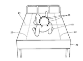
- FIG. 1 is a view for explaining the mounting position of the camera 151 of the safety nursing system in the embodiment of the present invention.
- camera 151 of the safety nursing system according to the present embodiment is arranged at a position where patient 10 on bed 20 can be imaged from the head direction.
- the camera 151 is arrange
- the camera 151 is disposed at a position where imaging is possible including the longitudinal ends 24 and 24 of the upper surface of the bed 20.
- the patient 10 is a person who needs to be watched by others such as a nurse who receives nursing care from a nurse such as a doctor and a nurse at a hospital, and a care recipient who receives care from a caregiver at a care facility. Including.
- FIG. 2 is a block diagram showing an outline of the configuration of the control device 100 of the safety nursing system in this embodiment.
- control device 100 includes a control unit 110, a storage unit 120, an operation unit 130, a display unit 140, an image input unit 150, an audio output unit 160, and a communication unit 190. .
- the control unit 110 includes a CPU (Central Processing Unit) and its auxiliary circuit, controls each unit of the control device 100, executes predetermined processing according to the program and data stored in the storage unit 120, the operation unit 130, the image Data input from the input unit 150 and the communication unit 190 is processed, and the processed data is stored in the storage unit 120, displayed on the display unit 140, or output as audio by the audio output unit 160, Or output from the communication unit 190.
- CPU Central Processing Unit
- the storage unit 120 includes a RAM (Random Access Memory) used as a work area necessary for the control unit 110 to execute a program, and a ROM (Read for storing a basic program to be executed by the control unit 110. Only Memory).
- a magnetic disk HD (Hard Disk), FD (Flexible Disk)), an optical disk (CD (Compact Disc)), a DVD (Digital Versatile Disk) ), BD (Blu-ray Disc)), magneto-optical disk (MO (Magneto-Optical disk)), or semiconductor memory (memory card, SSD (Solid State Drive)) or the like may be used.
- the operation unit 130 includes a keyboard and a mouse, and transmits an operation signal indicating an operation by the user to the control unit 110. Further, the operation unit 130 may be configured by another operation device such as a touch panel instead of or in addition to the keyboard and the mouse.
- Display unit 140 includes a display (for example, LCD (Liquid Crystal Display)).
- the display unit 140 is controlled by the control unit 110 to display a predetermined image on the display.
- the audio output unit 160 includes a speaker.
- the audio output unit 160 is controlled by the control unit 110 to output predetermined audio from the speaker.
- the image input unit 150 transfers the image data input from the camera 151 to the control unit 110, is controlled by the control unit 110, stores the image data in the storage unit 120, or displays the image data on the display unit 140.
- the communication unit 190 transmits information from the control unit 110 to another device (in this embodiment, the biological information monitor 200) via the network 900, and has been transmitted from another device via the network. Information is received and transferred to the control unit 110.
- the network 900 is a hospital LAN (Local Area Network), but is not limited to this, and may be another type of network such as a network via the Internet.
- the biological information monitor 200 measures biological information such as blood pressure and heart rate with a probe attached to a patient, and displays the measured biological information on the device or transmits it to another device via the network 900. To do.
- the camera 151 converts the captured image of the imaging range into image data, and transmits the image data to the image input unit 150 of the control device 100 in the present embodiment.
- the camera 151 captures a moving image.
- the present invention is not limited to this, and the camera 151 may capture a continuous still image at a short time interval (for example, every 0.1 second).
- FIG. 3 is a flowchart showing the flow of boundary condition setting processing executed by the control device 100 in this embodiment.
- control unit 110 acquires from storage unit 120 image data input from camera 151 to image input unit 150 and stored in storage unit 120.
- step S102 the control unit 110 extracts the bed side edges 23 and 23 and the longitudinal ends 24 and 24 from the image of the bed 20 indicated by the image data acquired in step S101.
- FIG. 4 is a first diagram showing an image captured by the camera 151 connected to the control device 100 in this embodiment.
- the image shown here includes patient 10 and bed 20, but it is desirable that patient 10 is not present when the boundary condition setting process of FIG. 3 is executed. .
- the camera 151 is disposed at a position where imaging is possible including the side edges 23 and 23 on both sides of the upper surface of the bed 20 from the head direction when the patient 10 lies on the bed 20. .
- the captured image includes an image of the upper surface of the bed 20 in a shape close to a trapezoid.
- the captured image includes an image of the upper surface of the bed 20 in a shape close to an isosceles trapezoid.
- the image to be captured includes a foot between the lower base and the upper base of the trapezoidal shape that is the shape of the upper surface of the bed 20, An image of the patient 10 is included so that is on the upper base side.
- the trapezoidal legs become the side edges 23 and 23 of the upper surface of the bed 20, and the upper and lower bases of the trapezoid become the longitudinal ends 24 and 24 of the upper surface of the bed 20.
- step S ⁇ b> 103 the control unit 110 defines a boundary in a predetermined condition for determining a predetermined action of the patient 10 based on the side ends 23 and 23 and the longitudinal ends 24 and 24 extracted in step S ⁇ b> 102. Lines 21 and 22 are calculated. After step S103, control unit 110 returns the process to be executed to the caller process of this process.
- the motion of moving the head As the predetermined motion of the patient 10, as will be described later with reference to FIG. 7, the motion of moving the head, the motion of getting up, the motion of rising, the warping motion, the motion of going down (from the bed 20), and , And the action of getting off (from the bed 20).
- the movement of moving the head can be regarded as a sign of an action that is about to rise, a sign of a rising action, and a sign of a crooking action.
- the motion that is about to rise can be regarded as a sign of the motion that rises.
- the crouching action can be regarded as an indication of an action about to get off the bed 20 and an indication of an action to get off the bed 20.
- the action about to get off the bed 20 can be regarded as a sign of the action to get off the bed 20.
- the patient 10 has (1) an action of moving his head, (2) an action of getting up, (3) an action of getting up, (4) an action of getting down from the bed 20, (5) from the bed 20 Operate in the order of descending movements.
- the patient 10 may also operate in other orders.
- the patient 10 operates in the order of (1) an operation of moving his / her head, (2) an operation of getting off the bed 20, and (3) an operation of getting off the bed 20.
- the action of getting off the bed 20 is literally the action of getting off the bed 20 when it gets off safely based on one's intention, but it is not possible to get off safely when it is not based on one's own intention In this case, the operation falls from the bed 20. That is, the operation of getting off the bed 20 includes the operation of getting off the bed 20 in addition to the operation of getting off the bed 20.
- the ratio of the feature points 15 exceeding the boundary line among the feature points 15 of the head of the patient 10 is a predetermined condition or more. When a predetermined condition is satisfied, it is determined that a predetermined operation has been performed.
- Algorithms such as SIFT (Scale-invariant feature transform) and SURF (Speeded Up Robust Features) can be used as algorithms for extracting feature points of an object (in this embodiment, patient 10).
- SIFT Scale-invariant feature transform
- SURF Speeded Up Robust Features
- the predetermined condition may be a condition in which the ratio of the movement vector exceeding the boundary line among the movement vectors of the feature point 15 of the head of the patient 10 is equal to or greater than the predetermined ratio.
- the movement vector of the feature point 15 is a vector of the amount and direction of movement of the feature point 15 from the previous predetermined frame to the current frame.
- Algorithms such as the above-mentioned SIFT and SURF can be used as the algorithm for calculating the movement vector of the feature point of the object (in this embodiment, the patient 10).
- the condition that the ratio of the movement vector approaching the boundary line among the movement vectors of the feature point 15 of the head of the patient 10 may be a predetermined ratio or more.
- boundary line is used in the above-described predetermined condition, it may be a long and narrow boundary region.
- the predetermined condition may be a condition that does not use a boundary line.
- it may be a condition that the amount of movement of the feature point 15 of the head of the patient 10 (that is, the magnitude of the movement vector) is equal to or greater than a predetermined ratio.
- the moving direction of the feature point 15 of the head of the patient 10 (that is, the direction of the moving vector) is a direction away from the bed 20 or a direction approaching the side edge of the bed 20 is a predetermined ratio or more. There may be.
- the moving speed of the feature point 15 of the head of the patient 10 (that is, unit time) It may be a condition that the feature points 15 whose magnitude of the movement vector is equal to or greater than a predetermined value (for example, 10 cm / second) are equal to or greater than a predetermined ratio.
- a predetermined value for example, 10 cm / second
- the head feature point 15 is used in the above-described predetermined condition, it may be a feature point of another part (for example, a shoulder).
- the predetermined ratio or more is set. However, when the number of feature points 15 is a fixed number, the predetermined number or more may be used.
- FIG. 5 is a diagram for explaining an example of a boundary line specifying method under a predetermined condition for determining a predetermined motion of a patient in this embodiment.
- the movement within the trapezoidal shape at the same distance as the two lines at the longitudinal ends 24, 24 of the bed 20 moves the head, It is assumed that the boundary line 21 is in a predetermined condition of the action to be performed and the action to rise.
- a line operation within a trapezoidal shape at an equal distance from the center line 25 in the longitudinal direction of the bed and the side edges 23 and 23 on both sides of the bed 20 The boundary lines 22 and 22 are defined under predetermined conditions for the operation of getting off the bed 20.
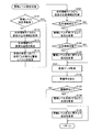
- FIG. 6 is a flowchart showing the flow of the alarm level setting process executed by the control device 100 in this embodiment.
- this alarm level setting process is a process for setting an alarm level for each patient 10 as to which notification is to be made for which operation.
- step S111 the control unit 110 determines whether the target patient 10 is a patient for which an alarm level has already been set. When it is determined that the patient is not a patient whose alarm level has already been set (when NO is determined in step S111), in step S112, the control unit 110 receives the biological information of the patient 10 from the biological information monitor 200 via the network 900. get.
- step S113 the control unit 110 specifies the condition of the patient 10 based on the biological information acquired in step S112. For example, if the blood pressure is a to b and ef, it is specified that the condition is bad. If the blood pressure is b to c and d to e, the condition is specified as medium. If the blood pressure is cd, the condition is identified as good.
- step S114 the control part 110 sets the predetermined operation
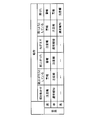
- FIG. 7 is a diagram used for setting a predetermined action and an alarm level for each patient in this embodiment.
- the warning level is used as a warning, and the movement of rising, the movement of rising
- the alarm level is set as an alarm for the action to get off (from the bed 20) and the action to get off (from the bed 20).
- the alarm level is usually annunciated for the movement of the head and the movement of the head, and the action of trying to get up, the action of getting up, and (the bed For actions that are about to go down (from 20), the alarm level is the warning, and for actions that get off (from the bed 20), the alarm level is the warning.
- the alarm level is normally notified for the action about to get off (from the bed 20), and the alarm level is the warning for the action to get off (from the bed 20).
- the warning, the warning information, and the normal notification are notifications that are easier to be transmitted to the nurse in this order.
- the alarm and the notification content are output, the lamp flashes, and the notification content is displayed. Is combined with the output of the voice of the notification content and the display of the character of the notification content, and the character of the notification content is displayed in the normal notification.
- step S ⁇ b> 121 the control unit 110 passes through the network 900.
- the biological information of the patient 10 is acquired from the biological information monitor 200.
- step S122 the control unit 110 determines whether the biological information of the patient 10 has deteriorated based on the biological information acquired in step S121.
- the condition in which the blood pressure is in the range from c to d is changed to the condition in which the blood pressure is in the condition from b to c and d to e.
- the biological information of the patient 10 deteriorates Judge that
- step S123 the control unit 110 changes the setting for the patient 10 to increase the alarm level set in step S114.
- the alarm level For example, increase the alarm level by 1 level for all actions. Specifically, for an operation in which the alarm level is a normal notification, the alarm level is increased to a warning, and for an operation in which the alarm level is a warning, the alarm level is increased to an alarm.
- step S124 the control unit 110 performs the process based on the biological information acquired in step S121. It is determined whether or not the biological information of the patient 10 has been recovered.
- the condition where the blood pressure is in the range of b to c and d to e is moderate, and the condition in which the blood pressure is in the range of c to d is good.
- the blood pressure changes from a poor state of ab, e to f to a moderate state of the blood pressure b to c, d to e the biological information of the patient 10 is recovered.
- step S125 the control unit 110 changes the setting so that the alarm level increased in step S123 is restored.
- the alarm level For every action, increase the alarm level by 1 level and decrease it by 1 level. Specifically, for an operation in which the alarm level is raised to the warning, the alarm level is lowered to normal notification, and for an operation in which the alarm level is raised to the warning, the alarm level is lowered to the warning.
- step S131 the control unit 110 is input from the camera 151 to the image input unit 150 and is stored in the storage unit.
- the image data stored in 120 is acquired from the storage unit 120.
- step S132 the control unit 110 extracts a nurse from the image data acquired in step S131.
- step S133 the control unit 110 determines whether there is a nurse.
- the extraction of the nurse is performed, for example, by extracting the nursing cap on the part determined to be the head, and when the nursing cap is extracted, it is determined that there is a nurse.
- a nurse may be extracted by extracting a stethoscope whose position is moving.
- a face included in the image indicated by the image data is extracted, and if the extracted face matches the face registered as a nurse, it is determined that there is a nurse. May be.
- step S134 the control unit 110 changes the setting so that the alarm level set in step S114 for the patient 10 is lowered.
- the alarm level For example, lower the alarm level one step at a time for all actions. Specifically, for an operation in which the alarm level is an alarm, the alarm level is lowered to a warning, and for an operation in which the alarm level is a warning, the alarm level is lowered to a normal notification.
- step S135 the control unit 110 changes the setting so as to restore the alarm level lowered in step S134.
- the alarm level For all actions, increase the alarm level by 1 level by decreasing the alarm level by 1 level. Specifically, for an operation in which the alarm level is lowered to the warning, the alarm level is raised to the alarm, and for an operation in which the alarm level is lowered to the normal notification, the alarm level is raised to the warning.
- step S134 and step S135 the control unit 110 returns the process to be executed to the caller process of this process.
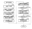
- FIG. 8 is a flowchart showing the flow of the operation determination process executed by the control device 100 in this embodiment.
- control unit 110 acquires from storage unit 120 the image data input from camera 151 to image input unit 150 and stored in storage unit 120.
- control part 110 extracts the feature point of the patient 10 from the image of the image data acquired at step S141 at step S142, and the feature point 15 of the head of the patient 10 among the feature points at step S143.
- step S144 the position of the feature point 15 of the head from the past image is calculated.
- the feature point 15 of the head of the patient 10 is the feature point of the object (in this embodiment, the patient 10) as described in step S ⁇ b> 103 of FIG. 3. Extracted by a conventional algorithm to extract, the position of the feature point 15 is calculated.
- step S151 the control unit 110 executes the following processing from step S152 to step S154 for the first operation for the patient.
- step S152 the control unit 110 calculates, based on the position calculated in step S144, the ratio of the feature points 15 that cross the boundary line of the predetermined condition corresponding to the motion among the feature points 15 of the head of the patient 10. calculate.
- step S153 control unit 110 determines whether or not the ratio calculated in step S152 is equal to or greater than a predetermined ratio.
- the ratio of the feature points 15 crossing the boundary line 21 parallel to the longitudinal end of the bed 20 is a predetermined ratio (10%) or more. If so, it is determined that the head has been moved.
- FIG. 9 is a second diagram illustrating an image captured by the camera 151 connected to the control device 100 according to this embodiment. Referring to FIG. 9, a state where the patient 10 is about to get up from the bed 20 is shown.
- FIG. 10 is a third diagram showing an image captured by the camera 151 connected to the control device 100 according to this embodiment. Referring to FIG. 10, this figure shows a state in which the patient 10 is about to get off the bed 20 or is being dropped.
- the ratio of the feature points 15 crossing the boundary line 22 parallel to the side edge of the bed 20 is (30%) or more in the case of an action about to get off the bed 20 or an action toward the falling direction If it is equal to or greater than a predetermined ratio, it is determined that the user is about to get off the bed 20 or is heading in a falling direction.
- the ratio of the feature points 15 crossing the boundary line 22 parallel to the side edge of the bed 20 is (95%) or more. If there is, it is determined that the user is getting off the bed 20 or is falling.
- step S154 the control unit 110 has an alarm level corresponding to the operation of the patient 10 set in step S114 of FIG. Informing that the operation has been performed.
- the alarm level is set as an alarm for an operation that is about to start up, if it is determined that the operation is about to start up, an alarm is sent that the user is about to start up.
- the alarm is sounded, a sound indicating that the user is about to start is output, the lamp is blinked, and the user is about to start up.
- the character of the effect is displayed.
- a voice message indicating that the user is about to start up is output and a character indicating that the user is about to start up is displayed.
- a character that says that he is going to get up is displayed.
- step S153 When it is determined that the ratio of the feature points 15 crossing the boundary line is not equal to or greater than the predetermined ratio (when NO is determined in step S153), and after step S154, whether or not the operation is performed in step S155 is determined. It is determined whether there is a next operation that has not been performed.
- step S155 If it is determined that there is a next operation (if YES is determined in step S155), the processing from step S152 to step S154 described above is performed for that operation. On the other hand, if it is determined that there is no next operation (step S155) If NO is determined in this step), the process to be executed is returned to the caller process of this process.
- the safety nursing system in the present embodiment is a system for monitoring the operation of the patient 10 on the bed 20, and includes the control device 100 and the side end 23 on the upper surface of the bed 20. , 23, and a camera 151 arranged at a position where imaging is possible.
- the control device 100 acquires image data captured by the camera 151, specifies the feature point 15 of the image of the patient 10 in the acquired image data, and performs a predetermined operation of the patient 10 (for example, the operation described in FIG. 7).
- a predetermined index for example, coordinates, moving amount, moving direction, moving speed
- a predetermined operation is performed based on the area of the bed 20 in the acquired image data.
- Predetermined conditions for example, the condition that the coordinates of the feature point 15 exceed a predetermined boundary for determining a predetermined action exceeds a predetermined threshold, and the degree of approaching the predetermined boundary
- a condition that a predetermined threshold value is exceeded a predetermined action is determined based on the calculated value and the set predetermined condition, and the condition is that the predetermined action is determined.
- 10 is indicative of the predetermined operation information (e.g., sound an alarm by the display, warning, normal notification) to the.
- the camera 151 is arranged at a position where the image including the side edges 23 and 23 on the upper surface of the bed 20 can be imaged, the image is not taken from the side of the bed 20. For this reason, it is possible to prevent troubles in nursing by the nurse.
- the movement of the patient 10 is determined based on a plurality of points, not the range. For this reason, it is possible to make it difficult for an error to appear in the determination result depending on the manner of operation and the body shape of the patient 10.
- the camera 151 is arranged at a position where the patient 10 can be imaged from the head direction or the foot direction. In this way, the positional relationship between the patient 10 and the side ends 23 and 23 of the bed 20 can be imaged in an easy-to-understand manner.
- the control device 100 calculates the value of the predetermined index of the feature point 15 included in the head region among the identified feature points. Thus, by monitoring the movement of the head, it is possible to monitor the movement of the patient 10 more efficiently compared to monitoring the movement of the whole body of the patient 10.
- the control device 100 calculates the coordinates of the feature point 15 as the value of the predetermined index, and as a predetermined condition, the plurality of coordinates determine a predetermined boundary (for example, a boundary for determining the predetermined action of the patient 10). Set conditions for lines and border areas.
- the control device 100 determines the degree to which the calculated coordinates exceed the set predetermined boundary (for example, the ratio of the number of feature points 15 exceeding the boundary within a predetermined time, the feature points 15 exceeding the boundary
- the predetermined operation is determined based on whether or not the ratio of the accumulated number of () has exceeded a predetermined threshold value (for example, a predetermined ratio).
- the control device 100 further calculates the moving direction of the feature point 15 as the value of the predetermined index, and the degree to which the calculated coordinates are approaching the predetermined boundary (for example, approaching the boundary within a predetermined time)
- the predetermined operation may be determined based on whether or not the ratio of the number of feature points 15 and the ratio of the cumulative number of feature points 15 approaching the boundary exceed a predetermined threshold value.
- the control device 100 determines a predetermined method based on the position of the side ends 23, 23 or the longitudinal ends 24, 24 of the bed 20 (for example, the length of the head side and foot side of the bed 20). Boundary line equidistant from the center line 25 in the longitudinal direction of the bed 20 and the side edges 23, 23 of the bed 20, using the boundary line 21 equidistant from each of the direction ends 24, 24 as a boundary for determination of rising.
- a predetermined condition is set in accordance with a method for determining whether or not 22 and 22 are to be moved to the end of the bed 20.
- the control device 100 has a plurality of types of predetermined actions and a plurality of alarm levels (for example, alarms, warnings, and normal notifications) according to the condition (for example, bad, medium, and good).
- the condition for example, bad, medium, and good.
- the value of a predetermined index used to determine the predetermined motion of the patient 10 is calculated, and the predetermined condition for determining the predetermined motion is set.
- the predetermined action is determined, and on the condition that the predetermined action is determined, the correspondence set for the patient 10 corresponding to the predetermined action Information indicating that the patient 10 has performed a predetermined action is output at the indicated alarm level.
- the control device 100 selects and sets the correspondence according to the condition of the patient from the correspondence between the predetermined action and the alarm level predetermined for each condition.
- the control device 100 identifies the condition of the patient 10 according to the information on the external biological information monitor 200, and from among the correspondence between the predetermined action and the alarm level predetermined for each condition, Select and set the correspondence according to the specified condition.
- the control device 100 determines whether or not the value indicated by the information on the external biological information monitor 200 has deteriorated. If it is determined that the value has deteriorated, the control device 100 performs the predetermined operation indicated by the set correspondence relationship. Change the correspondence to increase the alarm level.
- the setting of the correspondence of a predetermined action and an alarm level can be changed appropriately, and the notification that the predetermined action was performed according to the situation can be made appropriate.
- the control device 100 determines whether or not there is a nurse based on the acquired image data. If it is determined that there is a nurse, the alarm level for each predetermined operation indicated by the set correspondence relationship Change the correspondence to lower the
- the setting of the correspondence between the predetermined action and the alarm level can be appropriately changed depending on whether or not there is a nurse, and the notification that the predetermined action has been performed according to the situation can be made appropriate. it can.
- the control device 100 may determine whether or not there is a nurse based on the acquired image data, and may not output information when it is determined that there is a nurse.
- step S112 the process for each patient and the alarm level are automatically set by executing the processes from step S112 to step S114.
- the present invention is not limited to this, and a doctor or a nurse may specify the condition in step S112 and step S113. Alternatively, the doctor or nurse may be configured to manually set the operation and alarm level for each patient.
- step S122 it is determined that the biological information has deteriorated, and the setting is changed so as to increase the alarm level before the blood pressure value actually exceeds the danger value in an operation such as a rising operation. Also good.
- the camera 151 is arranged at a position where image capturing is possible including the side edges 23 and 23 on both sides of the upper surface of the bed 20.
- the present invention is not limited to this.
- the bed 20 The camera 151 may be arranged at a position where an image can be taken including the other side edge 23 of the upper surface.
- the boundary line is linear.
- the present invention is not limited to this, and the boundary line may be a closed curve shape such as a circle, an ellipse, or an arc, or an open curve shape.
- a circle having a predetermined radius from the head of the patient 10 in FIG. 4 may be used as the boundary line.
- the camera is arranged at a predetermined position in the vicinity of the bed 20, but the arrangement position of the control device 100 is not particularly mentioned.
- the control device 100 is preferably arranged at a position away from the bed 20 such as a nurse station, rather than arranged near the bed 20. In this way, when a nurse or caregiver is in the vicinity of the patient, the need for notifying the patient's action is low, but to a nurse or caregiver at a remote location where there is a high need for notification, The operation of the patient can be notified.
- the alarm corresponding to the operation of the patient 10 is performed on the display unit 140 and the audio output unit 160 of the control device 100 of the safety nursing system. Announced that the operation was performed at the level.
- the notification is not limited thereto, and such notification may be performed by a device different from the control device 100.
- FIG. 11 is a block diagram showing an outline of the configuration of a safety nursing system in a modification of this embodiment.
- this safety nursing system includes a PC 300 and a mobile phone 400 in addition to the configuration described above. Either the PC 300 or the mobile phone 400 may be included.
- the PC 300 and the mobile phone 400 are connected to the control device 100 via the network 900.
- the network 900 may include other types of networks such as a communication carrier mobile phone network and a local mobile phone network.
- control unit 110 of the control device 100 controls the communication unit 190 to provide information for notifying that the operation has been performed at an alarm level corresponding to the operation of the patient 10.
- the PC 300 or the mobile phone 400 notifies the fact that the PC 300 or the mobile phone 400 has performed the operation based on the received information at an alarm level corresponding to the operation of the patient 10. May be.
- the operation of the patient can be notified to a nurse or caregiver at a remote position where there is a high need for notification.
- the nurse or caregiver possesses the mobile phone 400, even if the nurse or caregiver is located away from the bed 20, the nurse or caregiver is notified of the patient's action. can do.
- a nurse or caregiver in charge of each patient may be determined in advance, and the operation of the patient may be notified to the mobile phone 400 possessed by the nurse or caregiver in charge of a patient.
- the operation of the patient other than the person in charge is not informed, only the operation of the patient in charge is informed, unnecessary notifications can be reduced, and the nurse and caregiver can take appropriate measures. Can contribute.
- the operation signal to the control unit 110 is input from the operation unit 130.
- an operation signal may be input from the PC 300 or the mobile phone 400 of FIG.
- control unit 110 of the control device 100 executes software as shown in the flowchart described above, the control unit 110 of the control device 100 performs the functions indicated by those processes.
- the portion to be configured is virtually configured.
- the present invention is not limited to this, and a part that exhibits these functions may be configured in the control unit 110 of the control device 100 by a hardware circuit.
- the invention has been described as the safety nursing system and the control device 100 included in the safety nursing system.
- the present invention is not limited to this, and can be understood as an invention of a control method of the safety nursing system or the control device 100 that executes the above-described processing in the safety nursing system or the control device 100.
Abstract
Description
(1) 前述した図6の警報レベル設定処理においては、ステップS112からステップS114の処理が実行されることによって患者ごとの動作と警報レベルとの設定が自動的に行なわれるようにした。しかし、これに限定されず、ステップS112およびステップS113での容態の特定を医師または看護師が行なうようにしてもよい。また、医師または看護師が患者ごとに動作と警報レベルとの設定を手動で行なえるように構成してもよい。 Next, a modification of the above-described embodiment will be described.
(1) In the alarm level setting process of FIG. 6 described above, the process for each patient and the alarm level are automatically set by executing the processes from step S112 to step S114. However, the present invention is not limited to this, and a doctor or a nurse may specify the condition in step S112 and step S113. Alternatively, the doctor or nurse may be configured to manually set the operation and alarm level for each patient.
Claims (8)
- ベッド(20)上の患者(10)の動作を監視する安全看護システム(100)であって、
制御部(110)と、
前記ベッドの上面の側端を含めて撮像可能な位置に配置される撮像部(151)とを備え、
前記制御部は、
前記撮像部で撮像された画像データを取得する撮像制御手段(ステップS141)と、
前記撮像制御手段によって取得された前記画像データにおける前記患者の画像の特徴点を特定し、前記患者の所定動作を判定するために用いられる当該特徴点の所定指標の値を算出する算出手段(ステップS142からステップS144)と、
前記撮像制御手段によって取得された前記画像データにおける前記ベッドの領域に基づいて、前記所定動作を判定するための所定条件を設定する設定手段と、
前記算出手段によって算出された前記値と前記設定手段によって設定された前記所定条件とに基づいて、前記所定動作を判定する判定手段(ステップS152,ステップS153)と、
前記判定手段によって前記所定動作をしたと判定されたことを条件として、前記患者が前記所定動作をした旨の情報を出力する出力手段(ステップS154)とを含む、安全看護システム。 A safety nursing system (100) for monitoring the movement of a patient (10) on a bed (20),
A control unit (110);
An imaging unit (151) disposed at a position where imaging is possible including the side edge of the upper surface of the bed,
The controller is
Imaging control means (step S141) for acquiring image data imaged by the imaging unit;
A calculation unit (step for identifying a feature point of the image of the patient in the image data acquired by the imaging control unit and calculating a value of a predetermined index of the feature point used for determining a predetermined motion of the patient S142 to step S144),
Setting means for setting a predetermined condition for determining the predetermined action based on the area of the bed in the image data acquired by the imaging control means;
Determination means (step S152, step S153) for determining the predetermined operation based on the value calculated by the calculation means and the predetermined condition set by the setting means;
A safety nursing system comprising: output means (step S154) for outputting information indicating that the patient has performed the predetermined action on the condition that the determination means has determined that the predetermined action has been performed. - 前記撮像部は、前記患者を頭部方向から撮像可能な位置に配置される、請求項1に記載の安全看護システム。 The safety nursing system according to claim 1, wherein the imaging unit is arranged at a position where the patient can be imaged from the head direction.
- 前記算出手段は、特定した前記特徴点のうち頭部の領域に含まれる前記特徴点の前記所定指標の値をそれぞれ算出する、請求項2に記載の安全看護システム。 3. The safety nursing system according to claim 2, wherein the calculation means calculates a value of the predetermined index of the feature point included in a head region among the specified feature points.
- 前記算出手段は、前記所定指標の値として、前記特徴点の座標を算出し、
前記設定手段は、前記所定条件として、複数の前記座標が前記患者の所定動作を判定するための所定の境界についての条件を設定する、請求項1に記載の安全看護システム。 The calculating means calculates the coordinates of the feature points as the value of the predetermined index,
The safety nursing system according to claim 1, wherein the setting unit sets a condition regarding a predetermined boundary for determining a predetermined motion of the patient as a plurality of the coordinates as the predetermined condition. - 前記判定手段は、前記算出手段によって算出された前記座標が、前記設定手段によって設定された前記所定の境界を超えた度合が所定のしきい値を超えたか否かによって、前記所定動作を判定する、請求項4に記載の安全看護システム。 The determination unit determines the predetermined operation based on whether or not the degree of the coordinates calculated by the calculation unit exceeding the predetermined boundary set by the setting unit exceeds a predetermined threshold value. The safety nursing system according to claim 4.
- 前記算出手段は、前記所定指標の値として、さらに、前記特徴点の移動方向を算出し、
前記判定手段は、前記算出手段によって算出された前記座標が前記所定の境界に近付いている度合が所定のしきい値を超えたか否かによって、前記所定動作を判定する、請求項4に記載の安全看護システム。 The calculation means further calculates a moving direction of the feature point as the value of the predetermined index,
5. The determination unit according to claim 4, wherein the determination unit determines the predetermined operation based on whether or not a degree of the coordinates calculated by the calculation unit approaching the predetermined boundary exceeds a predetermined threshold value. Safety nursing system. - 前記設定手段は、前記ベッドの側端または長手方向端の位置に基づいて、予め定められた特定方法に従って前記所定条件を設定する、請求項1に記載の安全看護システム。 The safety nursing system according to claim 1, wherein the setting means sets the predetermined condition according to a predetermined specific method based on a position of a side end or a longitudinal end of the bed.
- 制御部と、前記ベッドの上面の側端を含めて撮像可能な位置に固定して配置される撮像部とを備え、ベッド上の患者の動作を監視する安全看護システムを制御する制御方法であって、
前記制御部が、
前記撮像部で撮像された画像データを取得するステップと、
取得された前記画像データにおける前記患者の画像の特徴点を特定し、前記患者の所定動作を判定するために用いられる当該特徴点の所定指標の値を算出するステップと、
取得された前記画像データにおける前記ベッドの領域に基づいて、前記所定動作を判定するための所定条件を設定するステップと、
算出された前記値と設定された前記所定条件とに基づいて、前記所定動作を判定するステップと、
前記所定動作をしたと判定されたことを条件として、前記患者が前記所定動作をした旨の情報を出力するステップとを含む、安全看護システムの制御方法。 A control method for controlling a safety nursing system that includes a control unit and an imaging unit that is fixedly arranged at a position where imaging is possible including the side edge of the upper surface of the bed and that monitors the operation of a patient on the bed. And
The control unit is
Obtaining image data captured by the imaging unit;
Identifying a feature point of the image of the patient in the acquired image data and calculating a value of a predetermined index of the feature point used to determine a predetermined motion of the patient;
Setting a predetermined condition for determining the predetermined operation based on the area of the bed in the acquired image data;
Determining the predetermined action based on the calculated value and the set predetermined condition;
And a step of outputting information indicating that the patient has performed the predetermined operation on the condition that it is determined that the predetermined operation has been performed.
Priority Applications (3)
| Application Number | Priority Date | Filing Date | Title |
|---|---|---|---|
| DE112011103309T DE112011103309T5 (en) | 2010-09-29 | 2011-07-15 | Nursing safety system and method for controlling a care safety system |
| CN201180046306.5A CN103118589B (en) | 2010-09-29 | 2011-07-15 | Safe nursing system and method for controlling safe nursing system |
| US13/876,304 US8749626B2 (en) | 2010-09-29 | 2011-07-15 | Safe nursing system and method for controlling safe nursing system |
Applications Claiming Priority (2)
| Application Number | Priority Date | Filing Date | Title |
|---|---|---|---|
| JP2010-219192 | 2010-09-29 | ||
| JP2010219192A JP5682203B2 (en) | 2010-09-29 | 2010-09-29 | Safety nursing system and method for controlling safety nursing system |
Publications (1)
| Publication Number | Publication Date |
|---|---|
| WO2012043020A1 true WO2012043020A1 (en) | 2012-04-05 |
Family
ID=45892498
Family Applications (1)
| Application Number | Title | Priority Date | Filing Date |
|---|---|---|---|
| PCT/JP2011/066235 WO2012043020A1 (en) | 2010-09-29 | 2011-07-15 | Safe nursing system and method for controlling safe nursing system |
Country Status (5)
| Country | Link |
|---|---|
| US (1) | US8749626B2 (en) |
| JP (1) | JP5682203B2 (en) |
| CN (1) | CN103118589B (en) |
| DE (1) | DE112011103309T5 (en) |
| WO (1) | WO2012043020A1 (en) |
Cited By (2)
| Publication number | Priority date | Publication date | Assignee | Title |
|---|---|---|---|---|
| WO2016199748A1 (en) * | 2015-06-11 | 2016-12-15 | コニカミノルタ株式会社 | Motion detection system, motion detection device, motion detection method, and motion detection program |
| CN106971206A (en) * | 2017-04-13 | 2017-07-21 | 广东工业大学 | A kind of care actions wire examination method and system |
Families Citing this family (23)
| Publication number | Priority date | Publication date | Assignee | Title |
|---|---|---|---|---|
| GB2441550A (en) | 2006-09-05 | 2008-03-12 | Vision Rt Ltd | Surface-imaging breathing monitor |
| JP6171415B2 (en) * | 2013-03-06 | 2017-08-02 | ノーリツプレシジョン株式会社 | Information processing apparatus, information processing method, and program |
| JP6162517B2 (en) * | 2013-07-18 | 2017-07-12 | 東芝メディカルシステムズ株式会社 | Position determination support apparatus and medical image diagnostic apparatus |
| JP6544236B2 (en) * | 2013-09-13 | 2019-07-17 | コニカミノルタ株式会社 | Storage system, control device, image information storage method in storage system, control method in control device, and program |
| JP6047082B2 (en) * | 2013-09-13 | 2016-12-21 | 株式会社 日立産業制御ソリューションズ | Patient monitoring system |
| CN108107571B (en) * | 2013-10-30 | 2021-06-01 | 株式会社摩如富 | Image processing apparatus and method, and non-transitory computer-readable recording medium |
| RU2679868C1 (en) * | 2013-12-13 | 2019-02-13 | Конинклейке Филипс Н.В. | Sleep monitoring system and method |
| JP6245027B2 (en) * | 2014-03-26 | 2017-12-13 | 富士通株式会社 | Monitoring method, monitoring device, and monitoring program |
| EP3143931B1 (en) * | 2014-05-13 | 2020-12-09 | Omron Corporation | Posture estimation device and posture estimation method |
| US10121062B2 (en) * | 2014-11-03 | 2018-11-06 | Koninklijke Philips N.V. | Device, system and method for automated detection of orientation and/or location of a person |
| JP6455234B2 (en) * | 2015-03-03 | 2019-01-23 | 富士通株式会社 | Action detection method and action detection apparatus |
| JP2016213657A (en) * | 2015-05-08 | 2016-12-15 | 日本放送協会 | Encoded block size determination device, encoding device, and program |
| CN107851185A (en) * | 2015-08-10 | 2018-03-27 | 皇家飞利浦有限公司 | Take detection |
| JP2017194737A (en) | 2016-04-18 | 2017-10-26 | 富士通株式会社 | Bed area extraction program, bed area extraction method, and bed area extraction device |
| US10685551B2 (en) * | 2016-07-21 | 2020-06-16 | Sony Corporation | Information processing system, information processing apparatus, and information processing method |
| JP6406371B2 (en) | 2017-03-02 | 2018-10-17 | オムロン株式会社 | Watch support system and control method thereof |
| JP6635074B2 (en) | 2017-03-02 | 2020-01-22 | オムロン株式会社 | Watching support system and control method thereof |
| TWI671707B (en) * | 2018-06-15 | 2019-09-11 | 緯創資通股份有限公司 | Image analysis method, electronic system and non-transitory computer-readable recording medium |
| JP6582305B1 (en) * | 2019-01-11 | 2019-10-02 | Tdl株式会社 | Watch system, watch method and program. |
| JP6737355B2 (en) * | 2019-02-12 | 2020-08-05 | コニカミノルタ株式会社 | Head detection device, head detection method, and monitored person monitoring device |
| WO2021100815A1 (en) * | 2019-11-22 | 2021-05-27 | 社会福祉法人聖隷福祉事業団 | Movement data collection method, movement data analysis system, movement diagnosis assistance system, and analysis program |
| CN111479090B (en) * | 2020-04-15 | 2022-01-14 | Oppo广东移动通信有限公司 | Intelligent monitoring method, device, system and storage medium |
| CN111882823B (en) * | 2020-08-07 | 2022-04-22 | 歌尔科技有限公司 | Anti-falling control method and device, terminal equipment and storage medium |
Citations (5)
| Publication number | Priority date | Publication date | Assignee | Title |
|---|---|---|---|---|
| JP2004096457A (en) * | 2002-08-30 | 2004-03-25 | Sumitomo Osaka Cement Co Ltd | Area monitoring apparatus |
| JP2005128967A (en) * | 2003-10-27 | 2005-05-19 | Sozo Gijutsu Kenkyusho:Kk | Medical device, method and program for detecting movement and computer readable recording medium |
| JP2006175082A (en) * | 2004-12-24 | 2006-07-06 | Hitachi Engineering & Services Co Ltd | Uprising monitoring method and device |
| JP2006522959A (en) * | 2002-11-21 | 2006-10-05 | セキュマネジメント ビー.ヴイ. | Method and apparatus for fall prevention and detection |
| JP2009077908A (en) * | 2007-09-26 | 2009-04-16 | Shizuoka Prefecture | Care receiver movement detector and care receiver movement detecting method |
Family Cites Families (9)
| Publication number | Priority date | Publication date | Assignee | Title |
|---|---|---|---|---|
| JP2004049309A (en) * | 2002-07-16 | 2004-02-19 | National Trust:Kk | Monitoring system for person to be nursed or cared |
| US7035432B2 (en) * | 2003-07-22 | 2006-04-25 | Ronjo Company | Method of monitoring sleeping infant |
| JP3767898B2 (en) * | 2004-03-11 | 2006-04-19 | 国立大学法人山口大学 | Human behavior understanding system |
| GB2441550A (en) * | 2006-09-05 | 2008-03-12 | Vision Rt Ltd | Surface-imaging breathing monitor |
| DE102006057605A1 (en) * | 2006-11-24 | 2008-06-05 | Pilz Gmbh & Co. Kg | Method and device for monitoring a three-dimensional space area |
| KR20070003751A (en) * | 2006-12-16 | 2007-01-05 | 김종철 | Eye-based pointing interaction on computer graphical user interface |
| US20090044334A1 (en) * | 2007-08-13 | 2009-02-19 | Valence Broadband, Inc. | Automatically adjusting patient platform support height in response to patient related events |
| CN101510344A (en) * | 2009-03-24 | 2009-08-19 | 北京中星微电子有限公司 | Nursing system |
| CN201468678U (en) * | 2009-04-17 | 2010-05-19 | 张强 | Visible baby bed |
-
2010
- 2010-09-29 JP JP2010219192A patent/JP5682203B2/en active Active
-
2011
- 2011-07-15 CN CN201180046306.5A patent/CN103118589B/en active Active
- 2011-07-15 WO PCT/JP2011/066235 patent/WO2012043020A1/en active Application Filing
- 2011-07-15 DE DE112011103309T patent/DE112011103309T5/en active Pending
- 2011-07-15 US US13/876,304 patent/US8749626B2/en active Active
Patent Citations (5)
| Publication number | Priority date | Publication date | Assignee | Title |
|---|---|---|---|---|
| JP2004096457A (en) * | 2002-08-30 | 2004-03-25 | Sumitomo Osaka Cement Co Ltd | Area monitoring apparatus |
| JP2006522959A (en) * | 2002-11-21 | 2006-10-05 | セキュマネジメント ビー.ヴイ. | Method and apparatus for fall prevention and detection |
| JP2005128967A (en) * | 2003-10-27 | 2005-05-19 | Sozo Gijutsu Kenkyusho:Kk | Medical device, method and program for detecting movement and computer readable recording medium |
| JP2006175082A (en) * | 2004-12-24 | 2006-07-06 | Hitachi Engineering & Services Co Ltd | Uprising monitoring method and device |
| JP2009077908A (en) * | 2007-09-26 | 2009-04-16 | Shizuoka Prefecture | Care receiver movement detector and care receiver movement detecting method |
Cited By (3)
| Publication number | Priority date | Publication date | Assignee | Title |
|---|---|---|---|---|
| WO2016199748A1 (en) * | 2015-06-11 | 2016-12-15 | コニカミノルタ株式会社 | Motion detection system, motion detection device, motion detection method, and motion detection program |
| JP6222405B2 (en) * | 2015-06-11 | 2017-11-01 | コニカミノルタ株式会社 | Motion detection system, motion detection device, motion detection method, and motion detection program |
| CN106971206A (en) * | 2017-04-13 | 2017-07-21 | 广东工业大学 | A kind of care actions wire examination method and system |
Also Published As
| Publication number | Publication date |
|---|---|
| US20130215248A1 (en) | 2013-08-22 |
| US8749626B2 (en) | 2014-06-10 |
| CN103118589A (en) | 2013-05-22 |
| JP2012071003A (en) | 2012-04-12 |
| CN103118589B (en) | 2015-02-18 |
| DE112011103309T5 (en) | 2013-07-11 |
| JP5682203B2 (en) | 2015-03-11 |
Similar Documents
| Publication | Publication Date | Title |
|---|---|---|
| JP5682203B2 (en) | Safety nursing system and method for controlling safety nursing system | |
| JP5682204B2 (en) | Safety nursing system and method for controlling safety nursing system | |
| JP6717235B2 (en) | Monitoring support system and control method thereof | |
| US20150371522A1 (en) | Multi-Station System for Pressure Ulcer Monitoring and Analysis | |
| JP2011183121A (en) | Bedsore generation risk presentation device | |
| JP6708980B2 (en) | Image processing system, image processing device, image processing method, and image processing program | |
| EP3855451A1 (en) | Machine vision system to predict clinical patient parameters | |
| JP6273944B2 (en) | Status detection method, apparatus, and program | |
| JP6119938B2 (en) | Image processing system, image processing apparatus, image processing method, and image processing program | |
| JP2007072964A (en) | Bed-leaving prediction automatic sensing and notification method, and its automatic sensing and notification system | |
| US11213444B2 (en) | On-bed state monitoring system | |
| JP2022116277A (en) | Terminal device, output method, and computer program | |
| CN115223089B (en) | Children dangerous behavior detection method and device, intelligent terminal and storage medium | |
| JP7172483B2 (en) | STATE DETECTION DEVICE, STATE DETECTION METHOD, AND PROGRAM | |
| JP7130392B2 (en) | Display processing device, display processing method, and display processing program | |
| CN111723629B (en) | Gesture monitoring method and computing device and system thereof | |
| JP2019051097A (en) | Stay-in-bed state watching system | |
| US20200294674A1 (en) | Patient fall likelihood and severity | |
| JP2023041168A (en) | Monitor system, monitor method, and monitor program | |
| JP5982835B2 (en) | Detection apparatus, detection method, and detection program | |
| JP2023025761A (en) | Watching system, watching device, watching method, and watching program | |
| JP2016030180A (en) | Watching device |
Legal Events
| Date | Code | Title | Description |
|---|---|---|---|
| WWE | Wipo information: entry into national phase |
Ref document number: 201180046306.5 Country of ref document: CN |
|
| 121 | Ep: the epo has been informed by wipo that ep was designated in this application |
Ref document number: 11828581 Country of ref document: EP Kind code of ref document: A1 |
|
| WWE | Wipo information: entry into national phase |
Ref document number: 13876304 Country of ref document: US |
|
| WWE | Wipo information: entry into national phase |
Ref document number: 112011103309 Country of ref document: DE Ref document number: 1120111033095 Country of ref document: DE |
|
| 122 | Ep: pct application non-entry in european phase |
Ref document number: 11828581 Country of ref document: EP Kind code of ref document: A1 |