WO2012018001A1 - 映像処理装置、表示装置及び映像処理方法 - Google Patents
映像処理装置、表示装置及び映像処理方法 Download PDFInfo
- Publication number
- WO2012018001A1 WO2012018001A1 PCT/JP2011/067647 JP2011067647W WO2012018001A1 WO 2012018001 A1 WO2012018001 A1 WO 2012018001A1 JP 2011067647 W JP2011067647 W JP 2011067647W WO 2012018001 A1 WO2012018001 A1 WO 2012018001A1
- Authority
- WO
- WIPO (PCT)
- Prior art keywords
- video frame
- eye
- video
- frame
- unit
- Prior art date
- Legal status (The legal status is an assumption and is not a legal conclusion. Google has not performed a legal analysis and makes no representation as to the accuracy of the status listed.)
- Ceased
Links
Images




Classifications
-
- H—ELECTRICITY
- H04—ELECTRIC COMMUNICATION TECHNIQUE
- H04N—PICTORIAL COMMUNICATION, e.g. TELEVISION
- H04N13/00—Stereoscopic video systems; Multi-view video systems; Details thereof
- H04N13/10—Processing, recording or transmission of stereoscopic or multi-view image signals
- H04N13/106—Processing image signals
- H04N13/128—Adjusting depth or disparity
Definitions
- the present invention relates to a video processing device, a display device, and a video processing method capable of changing the parallax of the right-eye and left-eye video frames.
- a display device that alternately displays a left-eye video frame and a right-eye video frame having parallax, and allows a left-eye video and a right-eye video to be incident on a user's left eye and right eye, respectively, so as to visually recognize a stereoscopic video.
- the left-eye video frame and the right-eye video frame are generated by, for example, photographing the subject by two cameras arranged to have a predetermined parallax with respect to the subject.
- a left-eye video frame and a right-eye video frame having a predetermined parallax may be generated by processing a two-dimensional video frame (see, for example, Patent Document 1).
- the conventional technique has a problem that it is impossible to change the parallax of the left-eye video frame and the right-eye video frame.
- the purpose is to provide a left-eye video by providing a synthesizing unit that synthesizes a central video frame in which one of the video pairs displaced between the right-eye video frame and the left-eye video frame is arranged at a substantially central position of the video pair.
- An object of the present invention is to provide a video processing device, a display device, and a video processing method capable of changing the parallax between the frame and the right-eye video frame.
- the video processing device disclosed in the present application is a video processing device that processes a right-eye video frame and a left-eye video frame. From the right-eye video frame and the left-eye video frame, between the right-eye video frame and the left-eye video frame.
- An extraction unit that extracts a display position in each frame of the video pair that is deviated in the position
- a position calculation unit that calculates a substantially center position of the display position in each frame extracted by the extraction unit
- a synthesizing unit that synthesizes a central video frame arranged at a substantially central position calculated by the position calculating unit from the right-eye video frame and the left-eye video frame, and the central video frame obtained by synthesizing by the synthesizing unit.
- a generation unit that generates a display image frame for the right eye and a display image frame for the left eye using a predetermined parallax.
- a video pair consisting of a part of the left-eye video and the right-eye video having a parallax is included in each frame. It is extracted together with the display position within. The approximate center position of the display position in each extracted frame is calculated. A central video frame in which one of the extracted video pairs is arranged at the calculated approximate center position is synthesized from the right-eye video frame and the left-eye video frame as a two-dimensional video frame having no parallax. A right-eye display video frame and a left-eye display video frame having a predetermined parallax are generated based on the center video frame.
- the extraction unit further extracts a background video corresponding to a display position in each frame of the video pair from the left-eye video frame and the right-eye video frame
- the synthesis unit includes: A central video frame in which the background video extracted by the extraction unit is arranged at a display position in each frame of the video pair is synthesized.
- the right-eye video frame is included in an area other than the area where one of the video pairs having parallax extracted from the right-eye video frame and the left-eye video frame is arranged. Also, a background image extracted from the left-eye video frame is arranged.
- the video processing device disclosed in the present application includes a parallax calculation unit that calculates parallax included in the right-eye video frame and the left-eye video frame based on a display position in each frame extracted by the extraction unit, and the parallax calculation unit.
- a change unit that changes the calculated parallax, and the generation unit uses the parallax changed by the change unit.
- the parallax is calculated based on the amount of displacement of the image that is deviated between the right-eye video frame and the left-eye video frame.
- the calculated parallax is changed by being increased or decreased.
- a right-eye display video frame and a left-eye display video frame having a changed parallax are each generated from the central video frame.
- the video processing device disclosed in the present application includes a parallax calculation unit that calculates a parallax included in the right-eye video frame or the left-eye video frame based on the central video frame, and a change unit that changes the parallax calculated by the parallax calculation unit.
- the generation unit uses the parallax changed by the changing unit.
- the central video frame having no parallax is compared with the right-eye video frame and the left-eye video frame to calculate the parallax of the right-eye video frame and the left-eye video frame.
- the calculated parallax is changed by being increased or decreased.
- a right-eye display video frame and a left-eye display video frame having a changed parallax are each generated from the central video frame.
- the video processing device disclosed in the present application further includes a receiving unit that receives a parallax change instruction, and the changing unit changes the parallax according to the changing instruction received by the receiving unit.
- the video processing apparatus accepts a change instruction for increasing or decreasing the parallax from the user.
- the parallax of the right-eye video frame and the left-eye video frame is changed according to the received change instruction, and the right-eye display video frame and the left-eye display video frame having the changed parallax are generated.
- a display device disclosed in the present application is a display device that processes and displays a right-eye video frame and a left-eye video frame. From the right-eye video frame and the left-eye video frame, the right-eye video frame and the left-eye video frame are displayed.
- An extraction unit that extracts a display position in each frame of a video pair that is deviated between, a position calculation unit that calculates a substantially center position of a display position in each frame extracted by the extraction unit, and the video pair
- a synthesizing unit that synthesizes a central video frame arranged at a substantially central position calculated by the position calculating unit from the right-eye video frame and the left-eye video frame, and the central video frame obtained by synthesizing by the synthesizing unit Generating a right-eye display video frame and a left-eye display video frame using a predetermined parallax, and the right generated by the generation unit
- a display unit for displaying the use display image frame and the display video frame for the left eye.
- a video pair consisting of a part of the left-eye video and the right-eye video having a parallax is included in each frame. It is extracted together with the display position within. The approximate center position of the display position in each extracted frame is calculated.
- a central video frame in which one of the extracted video pairs is arranged at the calculated approximate center position is synthesized from the right-eye video frame and the left-eye video frame as a two-dimensional video frame having no parallax.
- a right-eye display video frame and a left-eye display video frame having a predetermined parallax are generated based on the center video frame. The generated right-eye display video frame and left-eye display video frame are displayed, and the user visually recognizes the stereoscopic video based on the changed parallax.
- the video processing method disclosed in the present application is a video processing method for processing a right-eye video frame and a left-eye video frame, and includes a right-eye video frame and a left-eye video frame between the right-eye video frame and the left-eye video frame.
- a center image in which the display position in each frame of the video pair that is deviated in is extracted, the approximate center position of the display position in each extracted frame is calculated, and one of the video pairs is arranged at the approximately center position Frames are synthesized from the right-eye video frame and the left-eye video frame, and a right-eye display video frame and a left-eye display video frame are generated using a predetermined parallax based on the center video frame.
- a video pair consisting of a part of the left-eye video and the right-eye video having a parallax is included in each frame. It is extracted together with the display position within. The approximate center position of the display position in each extracted frame is calculated. A central video frame in which one of the extracted video pairs is arranged at the calculated approximate center position is synthesized from the right-eye video frame and the left-eye video frame as a two-dimensional video frame having no parallax. A right-eye display video frame and a left-eye display video frame having a predetermined parallax are generated based on the center video frame.
- a synthesizing unit that synthesizes a central video frame in which one of a video pair displaced between a right-eye video frame and a left-eye video frame is arranged at a substantially central position of the video pair.
- FIG. 10 is a block diagram illustrating an example of internal hardware of a display device according to Embodiment 2.
- FIG. 12 is a block diagram illustrating an example of internal hardware of a display device according to Embodiment 3.
- FIG. FIG. 10 is a block diagram illustrating an example of internal hardware of a display device according to Embodiment 2.
- FIG. 10 is a block diagram illustrating an example of internal hardware of a display device according to a fourth embodiment. It is explanatory drawing for demonstrating the method to produce
- the display device receives the right-eye video frame and the left-eye video frame, and alternately displays the right-eye display video frame and the left-eye display video frame.
- a user of the display device wears an eyeglass device having a liquid crystal shutter or the like that opens and closes in synchronization with the right-eye display video frame and the left-eye display video frame that are alternately displayed on the display device. Then, the user visually recognizes the stereoscopic video by the left-eye video and the right-eye video that enter the left and right eyes via the eyeglass device.
- a display device for example, there is a receiver that receives and displays a television broadcast wave including a three-dimensional video signal.
- a display device that reproduces and displays a three-dimensional video signal recorded on a recording medium such as a DVD (Digital Versatile Disk) or a BD (Blu-ray Disk, registered trademark).
- the display device may be, for example, a game device that generates 3D video data according to a game application and displays a right-eye display video frame and a left-eye display video frame.
- the video processing apparatus is a video processing unit that is provided in a display device and generates a right-eye display video frame and a left-eye display video frame from a right-eye video frame and a left-eye video frame.
- the video processing device receives a right-eye video frame and a left-eye video frame, generates a left-eye display video frame and a right-eye display video frame with changed parallax, and outputs them to an external display device or recording device.
- This embodiment has a video processing unit, receives a video signal including a right-eye video frame and a left-eye video frame, and displays a right-eye display video frame and a left-eye display video frame as an example. I will give you a description.
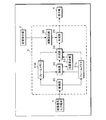
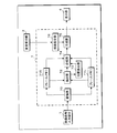
- FIG. 1 is a block diagram illustrating an example of internal hardware of a display device.
- the display device performs processing by a video signal input terminal 1 to which a video signal is input, a change receiving unit 2 that receives a parallax change instruction, a video processing unit 3 that processes the input video signal, and a video processing unit 3. And a display unit 4 for displaying a video signal.
- a video signal including a right-eye video frame and a left-eye video frame is input to the video signal input terminal 1.
- the video processing unit 3 changes the parallax of the right-eye video frame and the left-eye video frame included in the video signal in response to the parallax change instruction received by the change receiving unit 2, and displays the right-eye display video frame and the left-eye display.
- a video frame is generated and given to the display unit 4.
- the display unit 4 is, for example, a liquid crystal display or the like, and alternately displays the right-eye video and the left-eye video by alternately displaying the given right-eye display video frame and the left-eye display video frame.
- the right-eye video and the left-eye video displayed on the display unit 4 are incident on the eyes corresponding to the user through a not-shown spectacle device worn by the user of the display device, and the user visually recognizes the stereoscopic video.
- the change receiving unit 2 is, for example, a slider or a dial connected to a variable resistor, a potentiostat, or the like, and receives a change instruction indicating an increase or decrease in parallax when operated by a user.
- the video processor 3 stores an input video signal, a storage unit 30, frame memories 31 R and 31 L for extracting a right eye video frame and a left eye video frame from the video signal, a right eye video frame and a left eye, respectively.
- an extraction unit 32 that extracts a video pair that is deviated between video frames.
- the display device synthesizes a position calculation unit 33 that calculates a center position that is approximately the center of the display position in each frame of the extracted image, and a right-eye image frame and a left-eye image frame, which will be described later.
- a synthesis unit 34 that obtains a frame, and a parallax setting unit 36 that sets a parallax according to a change instruction given from the change receiving unit 2 are provided.
- the display device includes a generation unit 35 that generates a right-eye display video frame and a left-eye display video frame from the center video frame, the right-eye video frame, and the left-eye video frame based on the set parallax.
- the accumulation unit 30 is a memory, accumulates video signals sequentially input from the video signal input terminal 1, separates them into right-eye video frames and left-eye video frames, and sequentially supplies them to the frame memories 31 R and 31 L.
- the frame memories 31R and 31L are memories for storing frames for one frame, and the extraction unit 32 extracts a right-eye video frame for one frame and a left-eye video frame for one frame corresponding to the right-eye video frame. To give.
- the extraction unit 32 compares the right-eye video frame and the left-eye video frame for one frame given from the frame memories 31R and 31L, respectively, so that each of the videos shifted between the right-eye video frame and the left-eye video frame is displayed.
- the image is extracted from the frame as a video pair together with the display position in each frame, and is supplied to the position calculation unit 33 and the synthesis unit 34.
- the position calculation unit 33 calculates the center position of the display position in each frame of the video pair given from the extraction unit 32 and gives it to the synthesis unit 34.
- the synthesizing unit 34 extracts and synthesizes the background video from the right-eye video frame and the left-eye video frame given by the frame memories 31R and 31L, and further, one of the video pairs given from the extraction unit 32 is position calculation unit 33.
- a central video frame is obtained by arranging at a central position given by. Then, the synthesizing unit 34 provides the central video frame to the generating unit 35 together with the right-eye video frame and the left-eye video frame.
- the generation unit 35 uses the parallax set by the parallax setting unit 36 for the right-eye display video frame and the left-eye display video frame from the center video frame, the right-eye video frame, and the left-eye video frame given by the synthesis unit 34. Is generated and given to the display unit 4.
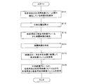
- FIG. 2 is a flowchart showing a procedure for changing the parallax of the right-eye video frame and the left-eye video frame.
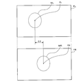
- FIG. 3 is an explanatory diagram for explaining a method of extracting a video pair that is displaced between the right-eye video frame and the left-eye video frame.
- FIG. 4 is an explanatory diagram for explaining a method of generating a central video frame.
- the extraction unit 32 extracts a video pair that is displaced between the right-eye video frame and the left-eye video frame (step S11). For the extraction of the video pair, first, the extraction unit 32 calculates the deviation amount of the display position in each video frame shown in the right-eye video frame and the display position in each video frame shown in the left-eye video frame. calculate.
- the extraction unit 32 may extract a video whose deviation amount exceeding a set threshold is calculated as a video pair from each of the right-eye video frame and the left-eye video frame.
- a conventional motion detection device may be used for the extraction of the video pair by the extraction unit 32.
- the motion detection device of the prior art compares a plurality of video frames included in a moving image in time series order, and detects the motion of the subject by detecting the video of the subject that is deviated between the frames.
- the motion detection device may be used to compare the right-eye video frame and the left-eye video frame, detect a video deviated between the frames, and extract a video pair.
- the images MR and ML of the same subject are shown in the display position PR in the frame of the right-eye video frame FR and the display position PL in the frame of the left-eye video frame FL.
- the distance between the display positions PR and PL is calculated as the displacement amount ⁇ X, and when the displacement amount ⁇ X exceeds the threshold value, the images MR and ML are extracted as image pairs.
- the position calculation unit 33 calculates a central position that is substantially the center of the display position in each frame of the video pair extracted by the extraction unit 32 (step S12).
- the synthesizing unit 34 extracts a video excluding the video pair extracted by the extraction unit 32 from the right-eye video frame and the left-eye video frame supplied from the frame memories 31R and 31L as a background video (step S13). Are synthesized (step S14).
- the synthesizing unit 34 obtains the central video frame by arranging one of the video pairs extracted by the extracting unit 32 with respect to the synthesized background video at the central position calculated by the position calculating unit 33 (step S15).
- one of the images MR and ML as the image pair extracted from the right-eye image frame FR and the left-eye image frame shown in FIG. 3 is displayed as the image MC at the display positions PR and PL. It is arranged at the central position PC.
- the partial areas AR and AL of the central video frame surrounded by broken lines shown in FIG. 4 correspond to the areas where the video MR and ML are displayed in the right-eye video frame FR and the left-eye video frame FL, respectively.
- the background video corresponding to the partial area AR is extracted and arranged from the left-eye video frame FL by the synthesis of the background video.
- the background image corresponding to the partial area AL is extracted from the right-eye video frame FR and arranged in the partial area AL by combining the background images.
- the generation unit 35 generates a right-eye display video frame and a left-eye display video frame using the parallax set by the parallax setting unit 36 from the central video frame, the right-eye video frame, and the left-eye video frame given from the synthesis unit 34. (Step S16) to complete the change of the parallax of the right-eye video frame and the left-eye video frame.
- the video of the subject in the central video frame is respectively displayed for the right-eye display frame and the left-eye display frame.
- the position to be displayed is calculated.
- the right-eye display frame and the left-eye display frame in which the video of the subject is arranged at each of the calculated positions are generated by synthesizing the right-eye video frame and the left-eye video frame.
- the background video extracted from the right-eye video frame and the left-eye video frame is arranged in a region excluding the subject video arranged in the right-eye display video frame and the left-eye display video frame.
- FIG. 5 is a schematic diagram showing a data layout example.
- FIG. 5 shows a video signal given to the video processing unit 3, a central video frame output from the synthesis unit 34, and a display video frame including a right-eye display video frame and a left-eye display video frame output from the generation unit 35. They are shown side by side from the top to the bottom.
- video signals in which left-eye video frames L1, L2, L3,... And right-eye video frames R1, R2, R3,. Have been entered.
- the synthesizing unit 34 combines the left-eye video frames L1, L2, L3,... And the right-eye video frames R1, R2, R3,..., And the central video frames C1, C2, C3,. Output sequentially.
- the generation unit 35 generates left-eye display video frames L1 ′, L2 ′, L3 ′, and right-eye display video frames R1 ′, R2 ′, R3 ′, generated from the center video frames C1, C2, C3,. ... each set is output sequentially.
- the display unit 4 displays the left-eye display video frames L1 ′, L2 ′, L3 ′, and the right-eye display video frames R1 ′, R2 ′, R3 ′,. .
- the present invention is not limited to this.
- the right-eye video frame and the left-eye video frame may be divided into a plurality of blocks having a predetermined number of pixels, and the partial videos displayed in each block may be compared between the frames.
- a block pair displaced between frames is extracted as a video pair.
- each pixel included in the right-eye video frame and the left-eye video frame may be compared between the frames, and a pixel pair displaced between the frames may be extracted as a video pair.
- the present invention is not limited to this, and the display position in each frame of the video pair and one of the video pairs are extracted. May be. In this case, one of the extracted video pairs is arranged in the central video frame.
- the right-eye display video frame and the left-eye display video frame are generated from the right-eye video frame, the left-eye video frame, and the midpoint video frame, the present invention is not limited thereto.
- a right-eye display video frame and a left-eye display video frame having a predetermined parallax may be generated from a central video frame that is a two-dimensional video by using a conventional technique for generating a right-eye display video frame and a left-eye display video frame.
- a video generated by interpolation processing based on a background video extracted from the central video frame may be arranged in a region excluding the subject video arranged in each of the right-eye display video frame and the left-eye display video frame.
- a computer executes a program read from a storage medium such as a memory, an optical disk, and a magnetic disk, and the computer realizes functions of each hardware of the video processing unit 3 according to the program.
- a RAM Random-Access Memory
- the parallax included in the input right-eye video frame and left-eye video frame can be changed.
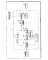
- FIG. 6 is a block diagram illustrating an example of internal hardware of the display device according to the second embodiment.
- the display device includes a video processing unit 5. Since the internal hardware parts of the display device excluding the video processing unit 5 are the same as those of the first embodiment, the same reference numerals are used and detailed description thereof is omitted.
- the video processing unit 5 combines the right-eye video frame and the left-eye video frame included in the video signal input to the video signal input terminal 1 to obtain a central video frame.
- the video processing unit 5 generates a right-eye display video frame and a left-eye display video frame from the central video frame using the parallax changed according to the user's parallax change instruction received by the change receiving unit 2, and the display unit Give to 4.
- the video processing unit 5 changes the parallax calculation unit 57 that calculates the parallax included in the right-eye video frame and the left-eye video frame, and changes the parallax calculated by the parallax calculation unit 57 according to the change instruction received by the change receiving unit 2.
- a change unit 58 Since other internal hardware units of the video processing unit 5 are the same as the video processing unit 3 of the first embodiment, only the difference in reference numerals is described.
- the video processing unit 5 includes a storage unit 50, frame memories 51R and 51L, an extraction unit 52, a position calculation unit 53, a synthesis unit 54, and a generation unit 55.
- the parallax calculation unit 57 calculates the parallax that the right-eye video frame and the left-eye video frame have based on the deviation amount of the video pair extracted by the extraction unit 52, and provides the parallax to the changing unit 58.
- the changing unit 58 changes the parallax given from the parallax calculating unit 57 in accordance with the change instruction received by the change receiving unit 2, and gives it to the generating unit 55.
- a change instruction for instructing increase or decrease can be received and changed with respect to the parallax included in the video frame for the right eye and the video frame for the left eye included in the video signal input to the video signal input terminal 1. It becomes possible.
- the second embodiment is as described above, and the others are the same as in the first embodiment. Therefore, the corresponding parts are denoted by the same reference numerals and processing names, and detailed description thereof is omitted.
- Embodiment 3 the parallax of the right-eye video frame and the left-eye video frame is calculated based on the deviation amount of the video pair extracted in the second embodiment, whereas the central video frame is used as the right-eye video. Calculate by comparing with the frame.
- FIG. 7 is a block diagram illustrating an example of internal hardware of the display device according to the third embodiment.
- the display device includes a video processing unit 6. Since the internal hardware parts of the display device excluding the video processing unit 6 are the same as those of the first embodiment, the same reference numerals are used and detailed description thereof is omitted.
- the video processing unit 6 combines the right-eye video frame and the left-eye video frame included in the video signal input to the video signal input terminal 1 to obtain a central video frame.
- the video processing unit 6 generates a right-eye display video frame and a left-eye display video frame from the center video frame using the parallax changed according to the change instruction received from the user by the change receiving unit 2, and give.
- the video processing unit 6 changes the parallax calculation unit 67 that calculates the parallax included in the right-eye video frame and the left-eye video frame, and changes the parallax calculated by the parallax calculation unit 67 according to the change instruction received by the change receiving unit 2.
- a change unit 68 Since other internal hardware units of the video processing unit 6 are the same as the video processing unit 3 of the first embodiment, only the difference in reference numerals is described.
- the video processing unit 6 includes a storage unit 60, frame memories 61R and 61L, an extraction unit 62, a position calculation unit 63, a synthesis unit 64, and a generation unit 65.
- the parallax calculation unit 67 detects a deviation amount of the subject image between the central video frame provided from the synthesis unit 64 and the right-eye video frame provided from the frame memory 61R, and based on the detected deviation amount. Parallax of the right-eye video frame and the left-eye video frame is calculated. For example, a value obtained by doubling the deviation amount of the subject image between the central video frame and the right-eye video frame may be calculated as the parallax of the right-eye video frame and the left-eye video frame. In the third embodiment, the case where the deviation amount of the subject image between the central video frame and the right-eye video frame is detected is shown, but the present invention is not limited to this, and the subject between the central video frame and the left-eye video frame is detected. The parallax may be calculated by detecting the deviation amount of the video.
- the third embodiment is as described above, and the other parts are the same as in the first embodiment. Therefore, the corresponding parts are denoted by the same reference numerals and processing names, and detailed description thereof is omitted.
- Embodiment 4 relates to a mode of generating a right-eye display video frame and a left-eye display video frame by applying frame frequency conversion including motion detection (hereinafter referred to as FRC (frame rate control)).
- FRC frame rate control
- FIG. 8 is a block diagram illustrating an example of internal hardware of the display device according to the fourth embodiment.
- the display device includes a video processing unit 7. Since the internal hardware parts of the display device excluding the video processing unit 7 are the same as those of the first embodiment, the same reference numerals are used and detailed description thereof is omitted.
- the video processing unit 7 combines the right-eye video frame and the left-eye video frame included in the video signal input to the video signal input terminal 1 by FRC to obtain a central video frame.
- the video processing unit 7 uses the acquired central video frame to generate a right-eye display video frame and a left-eye display video frame by FRC.
- the extraction unit 72 extracts a video pair that is displaced between the right-eye video frame and the left-eye video frame by motion detection.
- the extraction unit 72 compares the right-eye video frame and the left-eye video frame, detects a video deviated between the frames, and extracts a video pair.
- the video is detected even when the video portion moves in any direction, up, down, left, or right. Therefore, when other video parts that are not detection targets move up and down, an unintended video may be erroneously detected.
- the extraction unit 32 has no or little vertical movement and detects the video of the video part moving in the horizontal direction. Therefore, the extraction unit 32 suppresses the possibility of false detection lower than that of the normal motion detection. Can be extracted.
- the position calculation unit 73 calculates a central position that is substantially the center of the display position in each frame of the video pair extracted by the extraction unit 72.
- the position calculation unit 73 calculates the center position as follows, for example. Since the images MR and ML in FIG. 3 are always deviated only in the horizontal direction, the position calculation unit 73 creates a horizontal detection line including the images MR and ML, and detects edges of the images MR and ML. .
- the position calculation unit 73 calculates the center position from the left and right edge positions of each of the images MR and ML.
- the synthesizing unit 74 extracts a video excluding the video pair extracted by the extracting unit 72 from each of the right-eye video frame and the left-eye video frame given from the frame memories 71R and 71L as a background video, and synthesizes the background video.
- the background video for the center video frame, the right-eye display video frame, and the left-eye display video frame can be used for any video obtained by removing the video pair from the right-eye video frame and the left-eye video frame. There may be no. For this reason, there are cases where the background video for each video frame cannot be simply synthesized, but the synthesis unit 74 estimates a portion having no background video from the video determined as the background video, and synthesizes the background video. Alternatively, in the case where the surrounding area of the missing background video portion is a blank image, a video in which a simple shape pattern is repeated, etc., the compositing unit 74 complements the missing portion with the surrounding area video, You may synthesize.
- the FRC extracts a video part that has changed between two videos at close times, and interpolates or interpolates an intermediate video between the two extracted video parts, so that the intermediate between the two videos at the close time is obtained.
- This is a technology for generating video.
- the synthesizing unit 74 estimates and generates an intermediate video of the video pair by FRC interpolation or interpolation by replacing the right-eye video frame and the left-eye video frame with two images at close times.
- the video MC generated by the synthesizing unit 74 is an intermediate video between the video MR and ML in display position and form.
- the synthesizing unit 74 obtains the central video frame by arranging the video MC generated for the synthesized background video at the central position calculated by the position calculating unit 73.
- the generation unit 75 uses the parallax set by the parallax setting unit 76 from the central video frame, the right-eye video frame, and the left-eye video frame given from the synthesis unit 74, and performs the right-eye display video frame and the left-eye by FRC. Generate a display video frame.
- the parallax set by the parallax setting unit 76 may be larger or smaller than the parallax corresponding to the right-eye video frame and the left-eye video frame received by the video processing unit 7.
- the generation unit 75 When the parallax set by the parallax setting unit 76 is smaller than the parallax corresponding to the right-eye video frame and the left-eye video frame, the generation unit 75 performs the right-eye display video frame and the left-eye display video frame by FRC interpolation. Generate. When the parallax set by the parallax setting unit 76 is larger than the parallax corresponding to the right-eye video frame and the left-eye video frame, the generation unit 75 generates the right-eye display video frame and the left-eye display video frame by extrapolation of FRC. Generate. Extrapolation here is to estimate and generate a video corresponding to a past time or a future time closer to the time corresponding to two videos handled by the FRC.
- the accuracy related to the display position and form of the video interpolated or extrapolated by the FRC varies depending on the degree of positional or morphological difference between the two videos that are the source of the interpolation or extrapolation. That is, the accuracy regarding the display position or form of the video newly generated by FRC is higher as the positional or morphological difference between the two original videos is smaller, and the positional or morphological difference between the two original videos is higher. The larger the is, the lower it is.
- the accuracy of the video newly generated by the FRC further includes the color, luminance, shading, size, brightness, accuracy of the position and direction of the light source that illuminates the subject, and the position and direction of the viewpoint.
- the deviation amount includes a difference amount such as a display position and a form between two videos.
- FIG. 9 is an explanatory diagram for explaining a method of directly generating a right-eye display video frame and a left-eye display video frame from a right-eye video frame and a left-eye video frame.
- the upper part of FIG. 9 shows a left-eye video frame and a right-eye video frame.
- the lower part of FIG. 9 shows the left-eye display video frame. Display for left eye by FRC interpolation or extrapolation based on the amount of deviation between each subject in the left eye video frame, right eye video frame, left eye video frame and right eye video frame, and the set parallax A new video frame is generated.
- a new right-eye display video frame can be generated.
- FIG. 10 is an explanatory diagram for explaining a method of generating a right-eye display video frame and a left-eye display video frame from a right-eye video frame and a left-eye video frame via a center video frame.
- the upper part of FIG. 10 shows a left-eye video frame and a right-eye video frame.
- the middle part of FIG. 10 shows the left-eye video frame and the center video frame.
- the lower part of FIG. 10 shows the left-eye display video frame.
- the synthesizer 74 generates a central video frame by FRC interpolation from the right-eye video frame and the left-eye video frame. Therefore, the display position, form, and the like of the subject in the central video frame are substantially between those of the subjects in the right-eye video frame and the left-eye video frame.
- the generating unit 75 performs interpolation or extrapolation of FRC based on the deviation amount between the subjects in the left-eye video frame and the central video frame, the left-eye video frame and the central video frame, and the set parallax.
- a left-eye display video frame is newly generated by the insertion.
- the generation unit 75 performs interpolation or extrapolation of FRC based on the deviation amount between each subject in the right-eye video frame and the central video frame, the right-eye video frame and the central video frame, and the set parallax.
- a right-eye display video frame is newly generated by the insertion.
- the deviation amounts in the two video frames that are the basis for generating the left-eye display video frame are different between the case of FIG. 9 and the case of FIG. 10, and the deviation amount in FIG. 10 is approximately half of the deviation amount in FIG. It is. That is, the deviation amount between the right-eye video frame or the left-eye video frame and the central video frame is approximately half of the deviation amount between the right-eye video frame and the left-eye video frame. Since the accuracy of the video that is internally or extrapolated by the FRC is higher as the deviation amount related to the original video or video frame is smaller, the display device displays the right-eye display video frame and the left-eye display video frame via the central video frame. By generating, the accuracy of the generated video can be increased.
- the generation unit 75 uses the parallax set by the parallax setting unit 76, the video of the subject in the central video frame, and the video of the subject in the right-eye video frame or the left-eye video frame. Each subject to be displayed in each of the display video frame and the left-eye display video frame is generated by FRC.
- the generation unit 75 uses the parallax set by the parallax setting unit 76, the position of the subject in the central video frame, and the position of the subject in the right-eye video frame or the left-eye video frame. The position of each subject displayed in each of the display video frame and the left-eye display video frame is calculated.
- the generation unit 75 generates the right-eye display video frame and the left-eye display video frame in which the video of each subject is arranged at each calculated position with respect to the background video synthesized by the synthesis unit 74.
- the background video extracted from the right-eye video frame and the left-eye video frame is arranged in a region excluding the subject video arranged in the right-eye display video frame and the left-eye display video frame.
- the generation unit 75 may extract the background video of the central video frame synthesized by the synthesis unit 74, and set the extracted background video as the background video of the right-eye display video frame and the left-eye display video frame.
- the fourth embodiment is as described above, and the other parts are the same as those of the first embodiment. Therefore, the corresponding parts are denoted by the same reference numerals and processing names, and detailed description thereof is omitted.
- Video signal input terminal 2 Change accepting unit 3, 5, 6, 7 Video processing unit 30, 50, 60, 70 Storage unit 31R, 31L, 51R, 51L, 61R, 61L, 71R, 71L Frame memory 32, 52, 62 72 Extraction unit 33, 53, 63, 73 Position calculation unit 34, 54, 64, 74 Composition unit 35, 55, 65, 75 Generation unit 36, 76 Parallax setting unit 57, 67 Parallax calculation unit 58, 68 Change unit 4 Display section
Landscapes
- Engineering & Computer Science (AREA)
- Multimedia (AREA)
- Signal Processing (AREA)
- Controls And Circuits For Display Device (AREA)
- Testing, Inspecting, Measuring Of Stereoscopic Televisions And Televisions (AREA)
- Control Of Indicators Other Than Cathode Ray Tubes (AREA)
Abstract
本発明は、右目用及び左目用映像フレームが有する視差を変更することが可能となる映像処理装置、表示装置及び映像処理方法を提供する。 本発明の表示装置が有する映像処理部3は、右目用映像フレーム及び左目用映像フレームから、右目用映像フレーム及び左目用映像フレーム間で偏位している映像対の各フレーム内の表示位置を抽出する抽出部32と、抽出した各フレーム内の表示位置の略中央位置を算出する位置算出部33と、映像対の一方を算出した略中央位置に配置した中央映像フレームを右目用映像フレーム及び左目用映像フレームから合成する合成部34と、合成して得た中央映像フレームに基づき所定の視差を用いて右目用表示映像フレーム及び左目用表示映像フレームを生成する生成部35とを含む。
Description
本発明は、右目用及び左目用映像フレームが有する視差を変更することが可能となる映像処理装置、表示装置及び映像処理方法に関する。
視差を有する左目用映像フレーム及び右目用映像フレームを交互に表示し、ユーザの左目及び右目夫々に左目用映像及び右目用映像を入射させて立体映像を視認させる表示装置がある。左目用映像フレーム及び右目用映像フレームは、例えば、被写体に対して所定の視差を有するよう配置された2台のカメラ夫々により当該被写体が撮影されて生成される。また、2次元映像フレームを映像処理することにより、所定の視差を有する左目用映像フレーム及び右目用映像フレームが生成されることもある(例えば、特許文献1参照)。
しかしながら、従来技術では、左目用映像フレーム及び右目用映像フレームが有する視差を変更することが不可能であるという問題があった。
本願は、斯かる事情に鑑みてなされたものである。その目的は、右目用映像フレーム及び左目用映像フレーム間で偏位している映像対の一方を映像対の略中央位置に配置した中央映像フレームを合成する合成部を備えることにより、左目用映像フレーム及び右目用映像フレームの視差を変更することが可能となる映像処理装置、表示装置及び映像処理方法を提供することにある。
本願に開示する映像処理装置は、右目用映像フレーム及び左目用映像フレームを処理する映像処理装置において、前記右目用映像フレーム及び前記左目用映像フレームから、前記右目用映像フレーム及び左目用映像フレーム間で偏位している映像対の各フレーム内の表示位置を抽出する抽出部と、該抽出部により抽出した各フレーム内の表示位置の略中央位置を算出する位置算出部と、前記映像対の一方を前記位置算出部により算出した略中央位置に配置した中央映像フレームを前記右目用映像フレーム及び左目用映像フレームから合成する合成部と、該合成部により合成して得た前記中央映像フレームに基づき所定の視差を用いて右目用表示映像フレーム及び左目用表示映像フレームを生成する生成部とを備える。
本願にあっては、右目用映像フレーム及び左目用映像フレーム夫々に写っている左目用映像及び右目用映像のうち、視差を有する左目用映像及び右目用映像の一部からなる映像対が各フレーム内の表示位置と共に抽出される。抽出された各フレーム内の表示位置の略中央位置が算出される。抽出された映像対の一方を、算出した略中央位置に配置した中央映像フレームが、視差を有しない2次元映像フレームとして右目用映像フレーム及び左目用映像フレームから合成される。中央映像フレームに基づき所定の視差を有する右目用表示映像フレーム及び左目用表示映像フレームが生成される。
本願に開示する映像処理装置は、前記抽出部は、前記映像対の各フレーム内の表示位置に対応した背景映像を前記左目用映像フレーム及び右目用映像フレームから更に抽出し、前記合成部は、前記映像対の各フレーム内の表示位置に前記抽出部により抽出した背景映像を配置した中央映像フレームを合成する。
本願にあっては、中央映像フレームの全領域のうち、右目用映像フレーム及び左目用映像フレームから抽出された視差を有する映像対の一方が配置された領域以外の領域には、右目用映像フレーム及び左目用映像フレームから抽出された背景映像が配置される。
本願に開示する映像処理装置は、前記抽出部により抽出した各フレーム内の表示位置に基づいて前記右目用映像フレーム及び左目用映像フレームが有する視差を算出する視差算出部と、該視差算出部により算出した視差を変更する変更部とを更に備え、前記生成部は、前記変更部により変更した視差を用いる。
本願にあっては、右目用映像フレーム及び左目用映像フレーム間で偏位している映像の偏位量に基づいて視差が算出される。算出された視差は、増加又は減少されて変更される。変更された視差を有する右目用表示映像フレーム及び左目用表示映像フレーム夫々が中央映像フレームから生成される。
本願に開示する映像処理装置は、前記中央映像フレームに基づいて前記右目用映像フレーム又は左目用映像フレームが有する視差を算出する視差算出部と、該視差算出部により算出した視差を変更する変更部とを更に備え、前記生成部は、前記変更部により変更した視差を用いる。
本願にあっては、視差を有しない中央映像フレームと、右目用映像フレーム及び左目用映像フレーム夫々とが比較されて、右目用映像フレーム及び左目用映像フレームが有する視差が算出される。算出された視差は、増加又は減少されて変更される。変更された視差を有する右目用表示映像フレーム及び左目用表示映像フレーム夫々が中央映像フレームから生成される。
本願に開示する映像処理装置は、視差の変更指示を受付ける受付部を更に備え、前記変更部は、前記受付部により受付けた変更指示に応じて前記視差を変更する。
本願にあっては、映像処理装置がユーザから視差の増大又は減少させる変更指示を受付る。受付けた変更指示に従って右目用映像フレーム及び左目用映像フレームが有する視差が変更され、変更後の視差を有する右目用表示映像フレーム及び左目用表示映像フレームが生成される。
本願に開示する表示装置は、右目用映像フレーム及び左目用映像フレームを処理して表示する表示装置において、前記右目用映像フレーム及び前記左目用映像フレームから、前記右目用映像フレーム及び左目用映像フレーム間で偏位している映像対の各フレーム内の表示位置を抽出する抽出部と、該抽出部により抽出した各フレーム内の表示位置の略中央位置を算出する位置算出部と、前記映像対の一方を前記位置算出部により算出した略中央位置に配置した中央映像フレームを前記右目用映像フレーム及び左目用映像フレームから合成する合成部と、該合成部により合成して得た前記中央映像フレームに基づき所定の視差を用いて右目用表示映像フレーム及び左目用表示映像フレームを生成する生成部と、該生成部により生成した前記右目用表示映像フレーム及び左目用表示映像フレームを表示する表示部とを備える。
本願にあっては、右目用映像フレーム及び左目用映像フレーム夫々に写っている左目用映像及び右目用映像のうち、視差を有する左目用映像及び右目用映像の一部からなる映像対が各フレーム内の表示位置と共に抽出される。抽出された各フレーム内の表示位置の略中央位置が算出される。抽出された映像対の一方を、算出した略中央位置に配置した中央映像フレームが、視差を有しない2次元映像フレームとして右目用映像フレーム及び左目用映像フレームから合成される。中央映像フレームに基づき所定の視差を有する右目用表示映像フレーム及び左目用表示映像フレームが生成される。生成された右目用表示映像フレーム及び左目用表示映像フレームが表示されて、変更された視差に基づく立体映像をユーザが視認する。
本願に開示する映像処理方法は、右目用映像フレーム及び左目用映像フレームを処理する映像処理方法において、前記右目用映像フレーム及び前記左目用映像フレームから、前記右目用映像フレーム及び左目用映像フレーム間で偏位している映像対の各フレーム内の表示位置を抽出し、抽出した各フレーム内の表示位置の略中央位置を算出し、前記映像対の一方を前記略中央位置に配置した中央映像フレームを前記右目用映像フレーム及び左目用映像フレームから合成し、前記中央映像フレームに基づき所定の視差を用いて右目用表示映像フレーム及び左目用表示映像フレームを生成する。
本願にあっては、右目用映像フレーム及び左目用映像フレーム夫々に写っている左目用映像及び右目用映像のうち、視差を有する左目用映像及び右目用映像の一部からなる映像対が各フレーム内の表示位置と共に抽出される。抽出された各フレーム内の表示位置の略中央位置が算出される。抽出された映像対の一方を、算出した略中央位置に配置した中央映像フレームが、視差を有しない2次元映像フレームとして右目用映像フレーム及び左目用映像フレームから合成される。中央映像フレームに基づき所定の視差を有する右目用表示映像フレーム及び左目用表示映像フレームが生成される。
当該装置及び方法の一観点によれば、右目用映像フレーム及び左目用映像フレーム間で偏位している映像対の一方を映像対の略中央位置に配置した中央映像フレームを合成する合成部を備えることにより、左目用映像フレーム及び右目用映像フレームの視差を変更することが可能となる。
実施の形態1
以下、実施の形態を図面を参照して具体的に説明する。本願に係る表示装置は、右目用映像フレーム及び左目用映像フレームを受け付けて、右目用表示映像フレーム及び左目用表示映像フレームを交互に表示する。表示装置のユーザは、表示装置に交互に表示された右目用表示映像フレーム及び左目用表示映像フレームに同期して開閉する液晶シャッター等を有する眼鏡装置を装着する。そして、ユーザは、眼鏡装置を介して左右の眼夫々に入射する左目用映像及び右目用映像により立体映像を視認する。このような表示装置として、例えば、3次元映像信号を含むテレビジョン放送波を受信して表示する受像機がある。また、例えば、DVD( Digital Versatile Disk )又はBD( Blu-ray Disk、登録商標)等の記録媒体に記録された3次元映像信号を再生して表示する表示装置がある。
以下、実施の形態を図面を参照して具体的に説明する。本願に係る表示装置は、右目用映像フレーム及び左目用映像フレームを受け付けて、右目用表示映像フレーム及び左目用表示映像フレームを交互に表示する。表示装置のユーザは、表示装置に交互に表示された右目用表示映像フレーム及び左目用表示映像フレームに同期して開閉する液晶シャッター等を有する眼鏡装置を装着する。そして、ユーザは、眼鏡装置を介して左右の眼夫々に入射する左目用映像及び右目用映像により立体映像を視認する。このような表示装置として、例えば、3次元映像信号を含むテレビジョン放送波を受信して表示する受像機がある。また、例えば、DVD( Digital Versatile Disk )又はBD( Blu-ray Disk、登録商標)等の記録媒体に記録された3次元映像信号を再生して表示する表示装置がある。
更に、本願に係る表示装置は、例えば、ゲームアプリケーションに従って3次元映像データを生成し、右目用表示映像フレーム及び左目用表示映像フレームを表示するゲーム機器でもよい。本願に係る映像処理装置は、表示装置に設けられており、右目用映像フレーム及び左目用映像フレームから右目用表示映像フレーム及び左目用表示映像フレームを生成する映像処理部である。また、映像処理装置は、右目用映像フレーム及び左目用映像フレームを受け付けて、視差を変更した左目用表示映像フレーム及び右目用表示映像フレームを生成し、外部の表示装置又は記録装置へ出力するものでもよい。本実施の形態は、映像処理部を有しており、右目用映像フレーム及び左目用映像フレームを含む映像信号を受け付け、右目用表示映像フレーム及び左目用表示映像フレームを表示する表示装置を例に挙げて説明する。
図1は、表示装置の内部ハードウェアの例を示すブロック図である。表示装置は、映像信号が入力される映像信号入力端子1と、視差の変更指示を受付ける変更受付部2と、入力された映像信号を処理する映像処理部3と、映像処理部3により処理した映像信号を表示する表示部4とを有する。映像信号入力端子1には、右目用映像フレーム及び左目用映像フレームを含む映像信号が入力される。映像処理部3は、変更受付部2により受付けた視差の変更指示に応じて、映像信号に含まれる右目用映像フレーム及び左目用映像フレームの視差を変更して右目用表示映像フレーム及び左目用表示映像フレームを生成し、表示部4に与える。
表示部4は、例えば液晶ディスプレイ等であり、与えられた右目用表示映像フレーム及び左目用表示映像フレームを交互に表示することで、右目用映像及び左目用映像を交互に表示する。表示部4に表示された右目用映像及び左目用映像は、表示装置のユーザが装着する図示しない眼鏡装置を介して、ユーザの対応する目に入射され、ユーザは、立体映像を視認する。変更受付部2は、例えば、可変抵抗又はポテンショスタット等に接続されたスライダ又はダイヤルであり、ユーザが操作することにより、視差の増加又は減少を示す変更指示を受付ける。
映像処理部3は、入力された映像信号を蓄積する蓄積部30と、映像信号から右目用映像フレーム及び左目用映像フレーム夫々を抽出するためのフレームメモリ31R、31Lと、右目用映像フレーム及び左目用映像フレーム間で偏位した映像対を抽出する抽出部32とを有する。また、表示装置は、抽出した映像対夫々のフレーム内の表示位置の略中央となる中央位置を算出する位置算出部33と、右目用映像フレーム及び左目用映像フレームを合成して後述の中央映像フレームを得る合成部34と、変更受付部2から与えられた変更指示に応じて視差を設定する視差設定部36とを有する。更に、表示装置は、設定された視差に基づいて中央映像フレーム、右目用映像フレーム及び左目用映像フレームから右目用表示映像フレーム及び左目用表示映像フレーム夫々を生成する生成部35とを有する。
蓄積部30は、メモリであり、映像信号入力端子1から順次入力される映像信号を蓄積し、右目用映像フレーム及び左目用映像フレーム夫々に分離してフレームメモリ31R、31Lに順次与える。フレームメモリ31R、31Lは、1フレーム分のフレームを記憶するメモリであり、1フレーム分の右目用映像フレームと、当該右目用映像フレームに対応する1フレーム分の左目用映像フレームとを抽出部32に与える。抽出部32は、フレームメモリ31R、31L夫々から与えられた1フレーム分の右目用映像フレーム及び左目用映像フレームを比較することにより右目用映像フレーム及び左目用映像フレーム間で偏位した映像を各フレームから映像対として各フレーム内の表示位置と共に抽出し、位置算出部33及び合成部34に与える。
位置算出部33は、抽出部32から与えられた映像対の各フレーム内の表示位置の中央位置を算出して合成部34に与える。合成部34は、フレームメモリ31R、31Lにより与えられた右目用映像フレーム及び左目用映像フレームから背景映像を抽出して合成し、更に抽出部32から与えられた映像対の一方を位置算出部33から与えられた中央位置に配置して中央映像フレームを得る。そして、合成部34は、中央映像フレームを右目用映像フレーム及び左目用映像フレームと共に生成部35に与える。生成部35は、合成部34により与えられた中央映像フレーム、右目用映像フレーム及び左目用映像フレームから右目用表示映像フレーム及び左目用表示映像フレームを、視差設定部36により設定された視差を用いて生成し、表示部4に与える。
図2は、右目用映像フレーム及び左目用映像フレームが有する視差を変更する手順を示すフローチャートである。図3は、右目用映像フレーム及び左目用映像フレーム間で偏位している映像対を抽出する方法を説明するための説明図である。図4は、中央映像フレームを生成する方法を説明するための説明図である。抽出部32は、右目用映像フレーム及び左目用映像フレーム間で偏位している映像対を抽出する(ステップS11)。映像対の抽出は、始めに抽出部32により右目用映像フレームに写っている各映像のフレーム内の表示位置及び左目用映像フレームに写っている各映像のフレーム内の表示位置の偏位量を算出する。
そして、抽出部32は、設定してある閾値を超える偏位量が算出された映像を、右目用映像フレーム及び左目用映像フレーム夫々から映像対として抽出するとよい。抽出部32による映像対の抽出には、従来技術である動き検出装置を用いてもよい。従来技術の動き検出装置は、動画に含まれる複数の映像フレームを時系列順に比較し、フレーム間で偏位している被写体の映像を検出することで被写体の動きを検出する。この動き検出装置を用いて右目用映像フレーム及び左目用映像フレームを比較してフレーム間で偏位している映像を検出して、映像対を抽出するとよい。
例えば、図3に示す例では、同一被写体の映像MR、ML夫々が右目用映像フレームFRのフレーム内の表示位置PRと、左目用映像フレームFLのフレーム内の表示位置PLに写っている。表示位置PR、PL間の距離が偏位量ΔXとして算出され、偏位量ΔXが閾値を超える場合、映像MR、MLが映像対として抽出される。位置算出部33は、抽出部32により抽出された映像対の各フレーム内の表示位置の略中央となる中央位置を算出する(ステップS12)。合成部34は、フレームメモリ31R、31Lから与えられた右目用映像フレーム及び左目用映像フレーム夫々から抽出部32により抽出された映像対を除く映像を背景映像として抽出し(ステップS13)、背景映像を合成する(ステップS14)。
合成部34は、合成した背景映像に対して抽出部32により抽出した映像対の一方を位置算出部33により算出した中央位置に配置して中央映像フレームを取得する(ステップS15)。図4に示す例では、図3に示した右目用映像フレームFR及び左目用映像フレームから抽出された映像対としての映像MR、MLのうち、一方の映像が映像MCとして表示位置PR、PLの中央位置PCに配置されている。図4に示す破線で囲まれた中央映像フレームの部分領域AR、AL夫々は、映像MR、ML夫々が右目用映像フレームFR及び左目用映像フレームFLに表示されていた領域と対応する。
尚、部分領域ARには、前記の背景映像の合成により、当該部分領域ARに対応する背景映像が左目用映像フレームFLから抽出されて配置される。また、部分領域ALには、同様に前記の背景画像の合成により、当該部分領域ALに対応する背景映像が右目用映像フレームFRから抽出されて配置される。生成部35は、合成部34から与えられた中央映像フレーム、右目用映像フレーム及び左目用映像フレームから視差設定部36により設定された視差を用いて右目用表示映像フレーム及び左目用表示映像フレームを生成して(ステップS16)、右目用映像フレーム及び左目用映像フレームが有する視差の変更を完了する。
右目用映像フレーム及び左目用映像フレームの生成には、始めに視差設定部36により設定された視差に基づいて、中央映像フレームに写っている被写体の映像を右目用表示フレーム及び左目用表示フレーム夫々に表示する位置を算出する。そして、算出した位置夫々に被写体の映像を配置した右目用表示フレーム及び左目用表示フレームを右目用映像フレーム及び左目用映像フレームを合成して生成する。これにより、右目用表示映像フレーム及び左目用表示映像フレーム夫々に配置された被写体の映像を除く領域には、右目用映像フレーム及び左目用映像フレームから抽出した背景映像が配置される。
図5は、データレイアウト例を示す模式図である。図5は、映像処理部3に与えられる映像信号と、合成部34が出力する中央映像フレームと、生成部35が出力する右目用表示映像フレーム及び左目用表示映像フレームを含む表示映像フレームとを上段から下段へ並べて示している。図5に示す例では、左目用映像フレームL1、L2、L3、…及び右目用映像フレームR1、R2、R3、…が時系列に沿って交互に配置された映像信号が映像信号入力端子1に入力されている。合成部34は、左目用映像フレームL1、L2、L3、…夫々と、右目用映像フレームR1、R2、R3、…夫々とから合成されて得られた中央映像フレームC1、C2、C3、…を順次出力している。
生成部35は、中央映像フレームC1、C2、C3、…夫々から生成された左目用表示映像フレームL1´、L2´、L3´…夫々及び右目用表示映像フレームR1´、R2´、R3´、…夫々の組を順次出力している。表示部4は、生成部35から順次出力される左目用表示映像フレームL1´、L2´、L3´…夫々及び右目用表示映像フレームR1´、R2´、R3´、…夫々の組を表示する。
本実施の形態1では、右目用映像フレーム及び左目用映像フレームを比較することにより、フレーム間で偏位している映像対を抽出する場合を示したが、これに限るものではない。例えば、右目用映像フレーム及び左目用映像フレームを所定の画素数を有する複数のブロックに分割し、各ブロックに表示される部分映像をフレーム間で比較してもよい。この場合、フレーム間で偏位しているブロック対を映像対として抽出する。また、ブロックの代わりに右目用映像フレーム及び左目用映像フレームに含まれる各画素をフレーム間で比較して、フレーム間で偏位している画素対を映像対として抽出してもよい。
フレーム間で偏位している映像対を各フレーム内の表示位置と共に抽出する場合を示したが、これに限るものではなく映像対の各フレーム内の表示位置と、映像対の一方とを抽出してもよい。この場合、抽出された映像対の一方が中央映像フレームに配置される。右目用表示映像フレーム及び左目用表示映像フレームは、右目用映像フレーム、左目用映像フレーム及び中点映像フレームから生成する場合を示したが、これに限るものではない。例えば、2次元映像から所定の視差を有する右目用表示映像フレーム及び左目用表示映像フレームを生成する従来技術を用いて、2次元映像である中央映像フレームから生成してもよい。この場合、右目用表示映像フレーム及び左目用表示映像フレーム夫々に配置された被写体の映像を除く領域には、例えば中央映像フレームから抽出した背景映像に基づいて補間処理により生成した映像を配置するとよい。
右目用映像フレーム及び左目用映像フレームが有する視差を変更する処理は、映像処理部3が有する各ハードウェアにより実現される場合を示したが、これに限るものではない。例えば、映像処理部3の代わりにメモリ、光ディスク及び磁気ディスク等の記憶媒体から読み出したプログラムをコンピュータが実行し、コンピュータがプログラムに従って映像処理部3の各ハードウェアの機能を実現するようにしてもよい。また、この場合、フレームメモリの代わりにコンピュータが有するRAM( Random-Access Memory )を用いてもよい。
本実施の形態1は、設定された視差を用いて中央映像フレームから右目用表示映像フレーム及び左目用表示映像フレームを生成することにより、入力された右目用映像フレーム及び左目用映像フレームが有する視差を変更することが可能となる。
実施の形態2
本実施の形態は、実施の形態1が予め設定してある視差を変更するのに対して、入力された右目用映像フレーム及び左目用映像フレームが有する視差を算出して変更するようにしてある。図6は、実施の形態2に係る表示装置の内部ハードウェアの例を示すブロック図である。表示装置は、映像処理部5を有する。映像処理部5を除く表示装置の内部ハードウェア各部は、実施の形態1と同一であるので同一符号を用いて詳細な説明を省略する。映像処理部5は、映像信号入力端子1に入力された映像信号に含まれる右目用映像フレーム及び左目用映像フレームを合成して中央映像フレームを取得する。
本実施の形態は、実施の形態1が予め設定してある視差を変更するのに対して、入力された右目用映像フレーム及び左目用映像フレームが有する視差を算出して変更するようにしてある。図6は、実施の形態2に係る表示装置の内部ハードウェアの例を示すブロック図である。表示装置は、映像処理部5を有する。映像処理部5を除く表示装置の内部ハードウェア各部は、実施の形態1と同一であるので同一符号を用いて詳細な説明を省略する。映像処理部5は、映像信号入力端子1に入力された映像信号に含まれる右目用映像フレーム及び左目用映像フレームを合成して中央映像フレームを取得する。
映像処理部5は、変更受付部2により受け付けたユーザの視差の変更指示に応じて変更した視差を用いて、中央映像フレームから右目用表示映像フレーム及び左目用表示映像フレームを生成し、表示部4に与える。映像処理部5は、右目用映像フレーム及び左目用映像フレームが有する視差を算出する視差算出部57と、視差算出部57が算出した視差を変更受付部2により受け付けた変更指示に応じて変更する変更部58とを有する。映像処理部5の他の内部ハードウェア各部は、実施の形態1の映像処理部3と同様であるので、符号の違いを記載するに留める。映像処理部5は、蓄積部50と、フレームメモリ51R、51Lと、抽出部52と、位置算出部53と、合成部54と、生成部55とを有する。
視差算出部57は、抽出部52により抽出した映像対の偏位量に基づいて右目用映像フレーム及び左目用映像フレームが有する視差を算出し、変更部58に与える。変更部58は、変更受付部2により受け付けた変更指示に応じて、視差算出部57から与えられた視差を変更し、生成部55に与える。これにより、映像信号入力端子1に入力された映像信号に含まれる右目用映像フレーム及び左目用映像フレームが有する視差に対して、増大又は減少を指示する変更指示をユーザから受け付けて変更することが可能となる。
本実施の形態2は以上の如きであり、その他は実施の形態1と同様であるので対応する部分には同一の符号及び処理名を付してその詳細な説明を省略する。
実施の形態3
本実施の形態は、実施の形態2が抽出された映像対の偏位量に基づいて右目用映像フレーム及び左目用映像フレームが有する視差を算出するのに対して、中央映像フレームを右目用映像フレームと比較することにより算出する。図7は、実施の形態3に係る表示装置の内部ハードウェアの例を示すブロック図である。表示装置は、映像処理部6を有する。映像処理部6を除く表示装置の内部ハードウェア各部は、実施の形態1と同一であるので同一符号を用いて詳細な説明を省略する。映像処理部6は、映像信号入力端子1に入力された映像信号に含まれる右目用映像フレーム及び左目用映像フレームを合成して中央映像フレームを取得する。
本実施の形態は、実施の形態2が抽出された映像対の偏位量に基づいて右目用映像フレーム及び左目用映像フレームが有する視差を算出するのに対して、中央映像フレームを右目用映像フレームと比較することにより算出する。図7は、実施の形態3に係る表示装置の内部ハードウェアの例を示すブロック図である。表示装置は、映像処理部6を有する。映像処理部6を除く表示装置の内部ハードウェア各部は、実施の形態1と同一であるので同一符号を用いて詳細な説明を省略する。映像処理部6は、映像信号入力端子1に入力された映像信号に含まれる右目用映像フレーム及び左目用映像フレームを合成して中央映像フレームを取得する。
映像処理部6は、変更受付部2によりユーザから受け付けた変更指示に応じて変更した視差を用いて、中央映像フレームから右目用表示映像フレーム及び左目用表示映像フレームを生成し、表示部4に与える。映像処理部6は、右目用映像フレーム及び左目用映像フレームが有する視差を算出する視差算出部67と、視差算出部67が算出した視差を変更受付部2により受け付けた変更指示に応じて変更する変更部68とを有する。映像処理部6の他の内部ハードウェア各部は、実施の形態1の映像処理部3と同様であるので、符号の違いを記載するに留める。映像処理部6は、蓄積部60と、フレームメモリ61R、61Lと、抽出部62と、位置算出部63と、合成部64と、生成部65とを有する。
視差算出部67は、合成部64から与えられる中央映像フレームと、フレームメモリ61Rから与えられる右目用映像フレームとの間で被写体の映像の偏位量を検出し、検出した偏位量に基づいて右目用映像フレーム及び左目用映像フレームが有する視差を算出する。例えば、中央映像フレーム及び右目用映像フレーム間の被写体の映像の偏位量を2倍した値を、右目用映像フレーム及び左目用映像フレームが有する視差として算出するとよい。本実施の形態3では、中央映像フレーム及び右目用映像フレーム間の被写体の映像の偏位量を検出する場合を示したが、これに限るものではなく中央映像フレーム及び左目用映像フレーム間の被写体の映像の偏位量を検出して視差を算出してもよい。
本実施の形態3は以上の如きであり、その他は実施の形態1と同様であるので対応する部分には同一の符号及び処理名を付してその詳細な説明を省略する。
実施の形態4
本実施の形態は、動き検出を含むフレーム周波数変換(以下、FRC(frame rate control)と呼ぶ)を応用することにより、右目用表示映像フレーム及び左目用表示映像フレームを生成する形態に関する。
本実施の形態は、動き検出を含むフレーム周波数変換(以下、FRC(frame rate control)と呼ぶ)を応用することにより、右目用表示映像フレーム及び左目用表示映像フレームを生成する形態に関する。
図8は、実施の形態4に係る表示装置の内部ハードウェアの例を示すブロック図である。表示装置は、映像処理部7を有する。映像処理部7を除く表示装置の内部ハードウェア各部は、実施の形態1と同一であるので同一符号を用いて詳細な説明を省略する。映像処理部7は、映像信号入力端子1に入力された映像信号に含まれる右目用映像フレーム及び左目用映像フレームをFRCにより合成して中央映像フレームを取得する。映像処理部7は、取得した中央映像フレームを利用して、FRCにより右目用表示映像フレーム及び左目用表示映像フレームを生成する。
抽出部72は、右目用映像フレーム及び左目用映像フレーム間で偏位している映像対を、動き検出により抽出する。抽出部72は、右目用映像フレーム及び左目用映像フレームを比較してフレーム間で偏位している映像を検出し、映像対を抽出する。
尚、一般的な動き検出は、映像部分が上下左右いずれの方向に動く場合でもその映像を検出する。そのため、検出対象ではない他の映像部分が上下方向に動く場合、意図しない映像が誤検出される可能性がある。しかし、抽出部32は、上下方向の動きが全く又はほとんどなく、左右方向に動く映像部分の映像を検出対象とするので、通常の動き検出よりも誤検出の可能性を低く抑えて、映像対を抽出することができる。
尚、一般的な動き検出は、映像部分が上下左右いずれの方向に動く場合でもその映像を検出する。そのため、検出対象ではない他の映像部分が上下方向に動く場合、意図しない映像が誤検出される可能性がある。しかし、抽出部32は、上下方向の動きが全く又はほとんどなく、左右方向に動く映像部分の映像を検出対象とするので、通常の動き検出よりも誤検出の可能性を低く抑えて、映像対を抽出することができる。
位置算出部73は、抽出部72により抽出された映像対の各フレーム内の表示位置の略中央となる中央位置を算出する。位置算出部73は、例えば以下のように中央位置を算出する。図3における映像MR、MLは、必ず水平方向にのみ偏位していることから、位置算出部73は映像MR、MLを含む水平方向の検出ラインを作り、映像MR、MLのエッジを検出する。位置算出部73は、映像MR、ML夫々の左右端のエッジ位置から中央位置を算出する。
合成部74は、フレームメモリ71R、71Lから与えられた右目用映像フレーム及び左目用映像フレーム夫々から抽出部72により抽出された映像対を除く映像を背景映像として抽出し、背景映像を合成する。映像対の位置によっては、右目用映像フレーム及び左目用映像フレーム夫々から映像対が除かれたいずれの映像にも、中央映像フレーム、右目用表示映像フレーム及び左目用表示映像フレームのための背景映像がない場合がある。そのため、単純に各映像フレームのための背景映像を合成できない場合もあるが、合成部74は背景映像として確定している映像から背景映像がない部分を推定し、背景映像を合成する。あるいは、欠落した背景映像部分の周囲領域が無模様の映像、単純な形状パターンが繰り返された映像等である場合、周囲領域の映像により欠落部分を補完することにより、合成部74は背景映像を合成してもよい。
FRCは、近接した時刻の2つの映像の間で変化した映像部分を抽出し、抽出した2つの映像部分の中間の映像を内挿又は補間することにより、近接した時刻における2つの映像の中間の映像を生成する技術である。
合成部74は、右目用映像フレーム及び左目用映像フレームを近接した時刻の2つの画像に置き換えることにより、映像対の中間の映像をFRCの内挿又は補間により推定し、生成する。かかる場合、合成部74が生成する映像MCは、表示位置、形態等も映像MR、MLの中間の映像である。
合成部74は、合成した背景映像に対して生成した映像MCを位置算出部73により算出した中央位置に配置して中央映像フレームを取得する。
合成部74は、右目用映像フレーム及び左目用映像フレームを近接した時刻の2つの画像に置き換えることにより、映像対の中間の映像をFRCの内挿又は補間により推定し、生成する。かかる場合、合成部74が生成する映像MCは、表示位置、形態等も映像MR、MLの中間の映像である。
合成部74は、合成した背景映像に対して生成した映像MCを位置算出部73により算出した中央位置に配置して中央映像フレームを取得する。
生成部75は、合成部74から与えられた中央映像フレーム、右目用映像フレーム及び左目用映像フレームから、視差設定部76により設定された視差を用いて、FRCにより右目用表示映像フレーム及び左目用表示映像フレームを生成する。
視差設定部76により設定される視差は、映像処理部7が受け付けた右目用映像フレーム及び左目用映像フレームに対応する視差より大きい場合もあれば、小さい場合もある。視差設定部76により設定される視差が、右目用映像フレーム及び左目用映像フレームに対応する視差より小さい場合、生成部75は、FRCの内挿により右目用表示映像フレーム及び左目用表示映像フレームを生成する。視差設定部76により設定される視差が、右目用映像フレーム及び左目用映像フレームに対応する視差より大きい場合、生成部75は、FRCの外挿により右目用表示映像フレーム及び左目用表示映像フレームを生成する。
ここでの外挿とは、FRCが扱う2つの映像に対応する時刻よりも近接した過去の時刻又は未来の時刻に対応する映像を推定し、生成することである。
視差設定部76により設定される視差は、映像処理部7が受け付けた右目用映像フレーム及び左目用映像フレームに対応する視差より大きい場合もあれば、小さい場合もある。視差設定部76により設定される視差が、右目用映像フレーム及び左目用映像フレームに対応する視差より小さい場合、生成部75は、FRCの内挿により右目用表示映像フレーム及び左目用表示映像フレームを生成する。視差設定部76により設定される視差が、右目用映像フレーム及び左目用映像フレームに対応する視差より大きい場合、生成部75は、FRCの外挿により右目用表示映像フレーム及び左目用表示映像フレームを生成する。
ここでの外挿とは、FRCが扱う2つの映像に対応する時刻よりも近接した過去の時刻又は未来の時刻に対応する映像を推定し、生成することである。
FRCにより内挿又は外挿された映像の表示位置及び形態に関する精度は、内挿又は外挿の元となる2つの映像の位置的又は形態的差異の程度により異なる。すなわち、FRCにより新たに生成される映像の表示位置又は形態に関する精度は、元となる2つの映像の位置的又は形態的差異が小さいほど高く、元となる2つの映像の位置的又は形態的差異が大きいほど低い。ここでのFRCにより新たに生成される映像の精度は、更に色彩、輝度、濃淡、大きさ、明度、被写体を照らす光源の位置及び方向、視点の位置及び方向に関する精度を含む。以下、偏位量には、2つの映像間の表示位置、形態等の差異量が含まれるものとする。
FRCにより、右目用映像フレーム及び左用目映像フレームから直接新たな右目用表示映像フレーム及び左目用表示映像フレームを生成することもできる。
図9は、右目用映像フレーム及び左目用映像フレームから右目用表示映像フレーム及び左目用表示映像フレームを直接生成する方法を説明するための説明図である。図9の上段は、左目用映像フレーム及び右目用映像フレームを示す。図9の下段は、左目用表示映像フレームを示す。
左目用映像フレーム及び右目用映像フレーム、左目用映像フレーム及び右目用映像フレームにおける各被写体の間の偏位量、並びに設定された視差に基づいて、FRCの内挿又は外挿により、左目用表示映像フレームが新たに生成される。同様に、右目用表示映像フレームの新たな生成も可能である。
図9は、右目用映像フレーム及び左目用映像フレームから右目用表示映像フレーム及び左目用表示映像フレームを直接生成する方法を説明するための説明図である。図9の上段は、左目用映像フレーム及び右目用映像フレームを示す。図9の下段は、左目用表示映像フレームを示す。
左目用映像フレーム及び右目用映像フレーム、左目用映像フレーム及び右目用映像フレームにおける各被写体の間の偏位量、並びに設定された視差に基づいて、FRCの内挿又は外挿により、左目用表示映像フレームが新たに生成される。同様に、右目用表示映像フレームの新たな生成も可能である。
一方、本実施の形態に係る表示装置は、中央映像フレームを一旦生成し、中央映像フレームと右目用映像フレーム及び左目用映像フレームとから、新たな右目用表示映像フレーム及び左目用表示映像フレームを生成する。
図10は、右目用映像フレーム及び左目用映像フレームから、中央映像フレームを介して、右目用表示映像フレーム及び左目用表示映像フレームを生成する方法を説明するための説明図である。図10の上段は、左目用映像フレーム及び右目用映像フレームを示す。図10の中段は、左目用映像フレーム及び中央映像フレームを示す。図10の下段は、左目用表示映像フレームを示す。
合成部74は、右目用映像フレーム及び左目用映像フレームからFRCの内挿により、中央映像フレームを生成する。そのため、中央映像フレームにおける被写体の表示位置、形態等は、右目用映像フレーム及び左目用映像フレームにおける被写体のそれらの略中間である。
次に、生成部75は、左目用映像フレーム及び中央映像フレーム、左目用映像フレーム及び中央映像フレームにおける各被写体の間の偏位量、並びに設定された視差に基づいて、FRCの内挿又は外挿により、左目用表示映像フレームを新たに生成する。同様に、生成部75は、右目用映像フレーム及び中央映像フレーム、右目用映像フレーム及び中央映像フレームにおける各被写体の間の偏位量、並びに設定された視差に基づいて、FRCの内挿又は外挿により、右目用表示映像フレームを新たに生成する。
図10は、右目用映像フレーム及び左目用映像フレームから、中央映像フレームを介して、右目用表示映像フレーム及び左目用表示映像フレームを生成する方法を説明するための説明図である。図10の上段は、左目用映像フレーム及び右目用映像フレームを示す。図10の中段は、左目用映像フレーム及び中央映像フレームを示す。図10の下段は、左目用表示映像フレームを示す。
合成部74は、右目用映像フレーム及び左目用映像フレームからFRCの内挿により、中央映像フレームを生成する。そのため、中央映像フレームにおける被写体の表示位置、形態等は、右目用映像フレーム及び左目用映像フレームにおける被写体のそれらの略中間である。
次に、生成部75は、左目用映像フレーム及び中央映像フレーム、左目用映像フレーム及び中央映像フレームにおける各被写体の間の偏位量、並びに設定された視差に基づいて、FRCの内挿又は外挿により、左目用表示映像フレームを新たに生成する。同様に、生成部75は、右目用映像フレーム及び中央映像フレーム、右目用映像フレーム及び中央映像フレームにおける各被写体の間の偏位量、並びに設定された視差に基づいて、FRCの内挿又は外挿により、右目用表示映像フレームを新たに生成する。
左目用表示映像フレームを生成する元となる2つの映像フレームにおける偏位量は、図9の場合と図10の場合とで異なり、図10における偏位量は図9における偏位量の概ね半分である。すなわち、右目用映像フレーム又は左目用映像フレームと中央映像フレームとの間の偏位量は、右目用映像フレームと左目用映像フレームとの間の偏移量の概ね半分である。FRCにより内装又は外挿される映像の精度は、元となる映像又は映像フレームに係る偏位量が小さいほど高いので、表示装置は中央映像フレームを介して右目用表示映像フレーム及び左目用表示映像フレームを生成することにより、生成する映像の精度を高めることができる。
生成部75は、視差設定部76により設定された視差並びに、中央映像フレームに写っている被写体の映像及び、右目用映像フレーム又は左目用映像フレームに写っている被写体の映像に基づいて、右目用表示映像フレーム及び左目用表示映像フレーム夫々に表示する各被写体をFRCにより生成する。生成部75は、視差設定部76により設定された視差、並びに中央映像フレームに写っている被写体の位置及び、右目用映像フレーム又は左目用映像フレームに写っている被写体の位置に基づいて、右目用表示映像フレーム及び左目用表示映像フレーム夫々に表示する各被写体の位置を算出する。そして、生成部75は、合成部74が合成した背景映像に対して、算出した位置夫々に、各被写体の映像を配置した右目用表示映像フレーム及び左目用表示映像フレームを合成して生成する。
これにより、右目用表示映像フレーム及び左目用表示映像フレーム夫々に配置された被写体の映像を除く領域には、右目用映像フレーム及び左目用映像フレームから抽出した背景映像が配置される。
尚、生成部75は、合成部74が合成した中央映像フレームの背景映像を抽出し、抽出した背景映像を右目用表示映像フレーム及び左目用表示映像フレームの背景映像に設定してもよい。
これにより、右目用表示映像フレーム及び左目用表示映像フレーム夫々に配置された被写体の映像を除く領域には、右目用映像フレーム及び左目用映像フレームから抽出した背景映像が配置される。
尚、生成部75は、合成部74が合成した中央映像フレームの背景映像を抽出し、抽出した背景映像を右目用表示映像フレーム及び左目用表示映像フレームの背景映像に設定してもよい。
本実施の形態4は以上の如きであり、その他は実施の形態1と同様であるので対応する部分には同一の符号及び処理名を付してその詳細な説明を省略する。
1 映像信号入力端子
2 変更受付部
3、5、6、7 映像処理部
30、50、60、70 蓄積部
31R、31L、51R、51L、61R、61L、71R、71L フレームメモリ
32、52、62、72 抽出部
33、53、63、73 位置算出部
34、54、64、74 合成部
35、55、65、75 生成部
36、76 視差設定部
57、67 視差算出部
58、68 変更部
4 表示部
2 変更受付部
3、5、6、7 映像処理部
30、50、60、70 蓄積部
31R、31L、51R、51L、61R、61L、71R、71L フレームメモリ
32、52、62、72 抽出部
33、53、63、73 位置算出部
34、54、64、74 合成部
35、55、65、75 生成部
36、76 視差設定部
57、67 視差算出部
58、68 変更部
4 表示部
Claims (7)
- 右目用映像フレーム及び左目用映像フレームを処理する映像処理装置において、
前記右目用映像フレーム及び前記左目用映像フレームから、前記右目用映像フレーム及び左目用映像フレーム間で偏位している映像対の各フレーム内の表示位置を抽出する抽出部と、
該抽出部により抽出した各フレーム内の表示位置の略中央位置を算出する位置算出部と、
前記映像対の一方を前記位置算出部により算出した略中央位置に配置した中央映像フレームを前記右目用映像フレーム及び左目用映像フレームから合成する合成部と、
該合成部により合成して得た前記中央映像フレームに基づき所定の視差を用いて右目用表示映像フレーム及び左目用表示映像フレームを生成する生成部と
を備える映像処理装置。 - 前記抽出部は、
前記映像対の各フレーム内の表示位置に対応した背景映像を前記左目用映像フレーム及び右目用映像フレームから更に抽出し、
前記合成部は、
前記映像対の各フレーム内の表示位置に前記抽出部により抽出した背景映像を配置した中央映像フレームを合成する
請求項1に記載の映像処理装置。 - 前記抽出部により抽出した各フレーム内の表示位置に基づいて前記右目用映像フレーム及び左目用映像フレームが有する視差を算出する視差算出部と、
該視差算出部により算出した視差を変更する変更部と
を更に備え、
前記生成部は、前記変更部により変更した視差を用いる
請求項1又は請求項2に記載の映像処理装置。 - 前記中央映像フレームに基づいて前記右目用映像フレーム又は左目用映像フレームが有する視差を算出する視差算出部と、
該視差算出部により算出した視差を変更する変更部と
を更に備え、
前記生成部は、前記変更部により変更した視差を用いる
請求項1又は請求項2に記載の映像処理装置。 - 視差の変更指示を受付ける受付部を更に備え、
前記変更部は、前記受付部により受付けた変更指示に応じて前記視差を変更する
請求項3又は請求項4に記載の映像処理装置。 - 右目用映像フレーム及び左目用映像フレームを処理して表示する表示装置において、
前記右目用映像フレーム及び前記左目用映像フレームから、前記右目用映像フレーム及び左目用映像フレーム間で偏位している映像対の各フレーム内の表示位置を抽出する抽出部と、
該抽出部により抽出した各フレーム内の表示位置の略中央位置を算出する位置算出部と、
前記映像対の一方を前記位置算出部により算出した略中央位置に配置した中央映像フレームを前記右目用映像フレーム及び左目用映像フレームから合成する合成部と、
該合成部により合成して得た前記中央映像フレームに基づき所定の視差を用いて右目用表示映像フレーム及び左目用表示映像フレームを生成する生成部と、
該生成部により生成した前記右目用表示映像フレーム及び左目用表示映像フレームを表示する表示部と
を備える表示装置。 - 右目用映像フレーム及び左目用映像フレームを処理する映像処理方法において、
前記右目用映像フレーム及び前記左目用映像フレームから、前記右目用映像フレーム及び左目用映像フレーム間で偏位している映像対の各フレーム内の表示位置を抽出し、
抽出した各フレーム内の表示位置の略中央位置を算出し、
前記映像対の一方を前記略中央位置に配置した中央映像フレームを前記右目用映像フレーム及び左目用映像フレームから合成し、
前記中央映像フレームに基づき所定の視差を用いて右目用表示映像フレーム及び左目用表示映像フレームを生成する
映像処理方法。
Applications Claiming Priority (4)
| Application Number | Priority Date | Filing Date | Title |
|---|---|---|---|
| JP2010173950 | 2010-08-02 | ||
| JP2010-173950 | 2010-08-02 | ||
| JP2011167590A JP2012054912A (ja) | 2010-08-02 | 2011-07-29 | 映像処理装置、表示装置及び映像処理方法 |
| JP2011-167590 | 2011-07-29 |
Publications (1)
| Publication Number | Publication Date |
|---|---|
| WO2012018001A1 true WO2012018001A1 (ja) | 2012-02-09 |
Family
ID=45559498
Family Applications (1)
| Application Number | Title | Priority Date | Filing Date |
|---|---|---|---|
| PCT/JP2011/067647 Ceased WO2012018001A1 (ja) | 2010-08-02 | 2011-08-02 | 映像処理装置、表示装置及び映像処理方法 |
Country Status (2)
| Country | Link |
|---|---|
| JP (1) | JP2012054912A (ja) |
| WO (1) | WO2012018001A1 (ja) |
Families Citing this family (1)
| Publication number | Priority date | Publication date | Assignee | Title |
|---|---|---|---|---|
| KR101340308B1 (ko) * | 2012-06-08 | 2013-12-11 | 주식회사 마이씨에프 | 영상 처리 장치 및 방법 |
Citations (4)
| Publication number | Priority date | Publication date | Assignee | Title |
|---|---|---|---|---|
| JPH0927969A (ja) * | 1995-05-08 | 1997-01-28 | Matsushita Electric Ind Co Ltd | 複数画像の中間像生成方法及び視差推定方法および装置 |
| JP2000209614A (ja) * | 1999-01-14 | 2000-07-28 | Sony Corp | 立体映像システム |
| JP2003209858A (ja) * | 2002-01-17 | 2003-07-25 | Canon Inc | 立体画像生成方法及び記録媒体 |
| WO2009139740A1 (en) * | 2008-05-12 | 2009-11-19 | Thomson Licensing | System and method for measuring potential eyestrain of stereoscopic motion pictures |
Family Cites Families (1)
| Publication number | Priority date | Publication date | Assignee | Title |
|---|---|---|---|---|
| JP5556394B2 (ja) * | 2010-06-07 | 2014-07-23 | ソニー株式会社 | 立体画像表示システム、視差変換装置、視差変換方法およびプログラム |
-
2011
- 2011-07-29 JP JP2011167590A patent/JP2012054912A/ja active Pending
- 2011-08-02 WO PCT/JP2011/067647 patent/WO2012018001A1/ja not_active Ceased
Patent Citations (4)
| Publication number | Priority date | Publication date | Assignee | Title |
|---|---|---|---|---|
| JPH0927969A (ja) * | 1995-05-08 | 1997-01-28 | Matsushita Electric Ind Co Ltd | 複数画像の中間像生成方法及び視差推定方法および装置 |
| JP2000209614A (ja) * | 1999-01-14 | 2000-07-28 | Sony Corp | 立体映像システム |
| JP2003209858A (ja) * | 2002-01-17 | 2003-07-25 | Canon Inc | 立体画像生成方法及び記録媒体 |
| WO2009139740A1 (en) * | 2008-05-12 | 2009-11-19 | Thomson Licensing | System and method for measuring potential eyestrain of stereoscopic motion pictures |
Also Published As
| Publication number | Publication date |
|---|---|
| JP2012054912A (ja) | 2012-03-15 |
Similar Documents
| Publication | Publication Date | Title |
|---|---|---|
| EP2549762B1 (en) | Stereovision-image position matching apparatus, stereovision-image position matching method, and program therefor | |
| JP5917017B2 (ja) | 画像処理装置及びその制御方法、並びにプログラム | |
| US9215452B2 (en) | Stereoscopic video display apparatus and stereoscopic video display method | |
| US9007442B2 (en) | Stereo image display system, stereo imaging apparatus and stereo display apparatus | |
| US8704881B2 (en) | Stereoscopic image display apparatus | |
| US20140111627A1 (en) | Multi-viewpoint image generation device and multi-viewpoint image generation method | |
| US20120163701A1 (en) | Image processing device, image processing method, and program | |
| CN102326397B (zh) | 图像处理设备和图像处理方法 | |
| WO2010084724A1 (ja) | 画像処理装置、プログラム、画像処理方法、記録方法および記録媒体 | |
| US20090244258A1 (en) | Stereoscopic display apparatus, stereoscopic display method, and program | |
| US9167223B2 (en) | Stereoscopic video processing device and method, and program | |
| CN102379127A (zh) | 影像处理装置、影像处理方法以及计算机程序 | |
| WO2013108285A1 (ja) | 画像記録装置、立体画像再生装置、画像記録方法、及び立体画像再生方法 | |
| JP5521608B2 (ja) | 画像処理装置、および画像処理方法、並びにプログラム | |
| JP5396877B2 (ja) | 画像処理装置、プログラム、画像処理方法、および記録方法 | |
| US20110242294A1 (en) | Stereoscopic image display device and method of deriving motion vector | |
| JP5127973B1 (ja) | 映像処理装置、映像処理方法および映像表示装置 | |
| CN102547330A (zh) | 图像处理设备、图像处理方法和程序 | |
| JP4892105B1 (ja) | 映像処理装置、映像処理方法および映像表示装置 | |
| JP5915158B2 (ja) | タイムコード表示装置及びタイムコード表示方法 | |
| JP2014072809A (ja) | 画像生成装置、画像生成方法、画像生成装置用プログラム | |
| WO2012018001A1 (ja) | 映像処理装置、表示装置及び映像処理方法 | |
| JP2013171539A (ja) | 映像処理装置、映像処理方法及びコンピュータプログラム | |
| US9113140B2 (en) | Stereoscopic image processing device and method for generating interpolated frame with parallax and motion vector | |
| KR101192121B1 (ko) | 양안시차 및 깊이 정보를 이용한 애너그리프 영상 생성 방법 및 장치 |
Legal Events
| Date | Code | Title | Description |
|---|---|---|---|
| 121 | Ep: the epo has been informed by wipo that ep was designated in this application |
Ref document number: 11814626 Country of ref document: EP Kind code of ref document: A1 |
|
| NENP | Non-entry into the national phase |
Ref country code: DE |
|
| 122 | Ep: pct application non-entry in european phase |
Ref document number: 11814626 Country of ref document: EP Kind code of ref document: A1 |