WO2012015107A1 - 운전 중인 배전선로의 중성선 합성접지저항 측정방법 및 장치 - Google Patents
운전 중인 배전선로의 중성선 합성접지저항 측정방법 및 장치 Download PDFInfo
- Publication number
- WO2012015107A1 WO2012015107A1 PCT/KR2010/008338 KR2010008338W WO2012015107A1 WO 2012015107 A1 WO2012015107 A1 WO 2012015107A1 KR 2010008338 W KR2010008338 W KR 2010008338W WO 2012015107 A1 WO2012015107 A1 WO 2012015107A1
- Authority
- WO
- WIPO (PCT)
- Prior art keywords
- neutral
- measuring
- distribution line
- ground resistance
- voltage
- Prior art date
- Legal status (The legal status is an assumption and is not a legal conclusion. Google has not performed a legal analysis and makes no representation as to the accuracy of the status listed.)
- Ceased
Links
Images


Classifications
-
- G—PHYSICS
- G01—MEASURING; TESTING
- G01R—MEASURING ELECTRIC VARIABLES; MEASURING MAGNETIC VARIABLES
- G01R27/00—Arrangements for measuring resistance, reactance, impedance, or electric characteristics derived therefrom
- G01R27/02—Measuring real or complex resistance, reactance, impedance, or other two-pole characteristics derived therefrom, e.g. time constant
- G01R27/16—Measuring impedance of element or network through which a current is passing from another source, e.g. cable, power line
- G01R27/18—Measuring resistance to earth, i.e. line to ground
-
- G—PHYSICS
- G01—MEASURING; TESTING
- G01R—MEASURING ELECTRIC VARIABLES; MEASURING MAGNETIC VARIABLES
- G01R31/00—Arrangements for testing electric properties; Arrangements for locating electric faults; Arrangements for electrical testing characterised by what is being tested not provided for elsewhere
- G01R31/50—Testing of electric apparatus, lines, cables or components for short-circuits, continuity, leakage current or incorrect line connections
- G01R31/52—Testing for short-circuits, leakage current or ground faults
Definitions
- the present invention includes an AC power source capable of varying the magnitude of the current to inject a current into the measuring point of the neutral composite ground resistance, and provides a measuring wire for measuring the injection current and potential and a lead wire for current supply and voltage measurement to the neutral wire.
- the present invention relates to a method for measuring neutral ground composite ground resistance of a distribution line in operation consisting of an insulated operating rod for connection, and a measuring apparatus thereof.
- a method of measuring ground resistance is a potential drop method, in which a current auxiliary electrode (C) is installed far from the measurement target ground electrode (E), and a resistance distribution curve for each distance is moved while moving the voltage auxiliary electrode (P). Drawing (Fig. 2), the measurement result of the horizontal part of the distribution curve is determined as the ground resistance value.
- This method has a problem that it is difficult to apply to the distribution line in operation because the measuring ground electrode must be separated from other grounding facilities to measure.
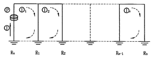
- Another method is to supply a voltage E to the grounded electrode (Rx) circuit to be measured using a special current transformer in a multi-ground (each ground resistance Rk) system.
- the relationship between the current and the voltage is established as in Equation 1 (see Fig. 1).
- this method has a problem that the ground wire is exposed to the outside of the power distribution pole so that the operator can measure it, or by approaching to the neutral line near the neutral line using a live wheel, there is a risk of time, manpower and safety accidents, and accuracy is low. .
- the conventional method can not accurately measure the value of the neutral composite earth resistance fundamentally, and in the calculation method, since a parallel compound resistance calculation formula of a general direct current circuit is used, a large number of errors are generated from the actual values. Since these errors are generally dozens or more of synthetic ground resistance values, the individual ground resistance values have a large variation range, and thus there is a problem in that unnecessary construction and management costs are generated under the current standards for managing individual ground resistance values.
- the measurement method disclosed in Korean Patent Laid-Open Publication No. 10-0445755 is a method for measuring the individual ground resistance (Rx) value by assuming that the resistance values on the left and right sides of the measurement resistance Rx are almost zero (0).
- Korean Patent Publication No. 10-0734821 since the error of the potential interference effect of the auxiliary electrode is not taken into account, all of them have a problem in that the accurate neutral conductor grounding resistance cannot be obtained.
- the problem to be solved by the present invention is to reduce the installation and maintenance costs by efficiently measuring the combined resistance of the multi-ground distribution line in operation of several to several tens of kilometers to install the ground point to a minimum location.
- Another problem to be solved by the present invention is to measure the potential interference coefficient that is converted according to the distance between the pole and the voltage auxiliary electrode and to apply it to the calculation algorithm to minimize the measurement error, so that the grounding installation and maintenance cost of the distribution line To greatly reduce the cost.
- Another problem to be solved by the present invention is to inject a current signal different from the 60 kHz frequency of a commercial AC power source when injecting a current to the neutral composite earth resistance measurement point, and the FFT is a specific frequency generated by the injection current using Matlab By selecting only the potential waveform and calculating the voltage, it is possible to obtain the neutral grounded ground resistance of the multi-ground distribution line that is operating correctly.
- the present invention includes an AC power source capable of converting a magnitude of a current and a voltage to inject a current into a neutral composite ground resistance measurement point.
- the present invention provides a neutral composite ground resistance measuring apparatus for a distribution line in operation composed of an insulated operating rod for connecting a voltage measuring lead.
- the present invention also provides an AC power source capable of converting the magnitude of the current and the voltage to inject a current into the neutral composite ground resistance measurement point, and injects a current into the voltage measurement point through the lead wire of the insulated operating rod.
- a method for measuring the neutral ground resistance of the distribution line in operation comprising the steps of: measuring the injection current and the potential using a measuring instrument; and calculating reactance using the voltage magnitude and the injection current measured by the measuring instrument. It is.
- a potential interferometer that includes a current auxiliary electrode R_c and a potential auxiliary electrode R_v in a circuit for measuring an injection current and a potential, and changes according to a distance between a pole and a voltage auxiliary electrode.
- the potential interference coefficient K can be calculated by Equation (2).
- Another solution of the present invention is to inject a current signal different from the 60 kHz frequency of a commercial AC power supply when injecting a current to the neutral composite ground resistance measurement point, and the FFT is a specific frequency generated by the injection current using Matlab
- the present invention provides a neutral composite ground resistance measuring apparatus for a distribution line in operation that can obtain an accurate neutral composite ground resistance by selecting a potential waveform and calculating a voltage.
- the present invention has an advantageous effect of accurately measuring the combined resistance of the multi-ground distribution line in operation of several to several tens of kilometers and efficiently installing and maintaining the ground point at a minimum location, thereby reducing installation and maintenance costs.
- Another effect of the present invention is to measure the potential interference coefficient that is converted according to the distance between the pole and the voltage auxiliary electrode and to apply it to a calculation algorithm to minimize the measurement error, which enables efficient grounding and greatly increases the cost of installing and maintaining the distribution line. To save.
- Another effect of the present invention is to minimize the measurement error by developing and applying a correction coefficient calculating means according to the position of the auxiliary electrode in order to improve the accuracy of the measured value of the neutral composite ground resistance.
- Another effect of the present invention is to inject a current that is different from the 60 kHz frequency of a commercial AC power supply when injecting a current to the neutral composite ground resistance measurement point, and the FFT is a specific frequency potential waveform generated by the injection current using Matlab only. By selecting and calculating the voltage, it is possible to obtain accurate neutral ground resistance.
- FIG. 2 is an explanatory diagram of a synthetic ground resistance measurement circuit composed of an injection current electrode and a voltage measurement electrode centered on the ground resistance;
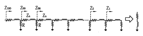
- 3 is a circuit model used to determine whether convergence by receiving the line constant, ground and line distance information according to the present invention
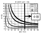
- FIG. 4 is a diagram illustrating a track distance at which a synthesized impedance is converged by simulation.
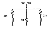
- Fig. 5 is a circuit diagram showing the ground resistance Rg of the pole pole and the Thevenin equivalent composite impedance Zth in both directions at the measurement point.
- FIG. 6 is a flowchart of a method for measuring the neutral ground resistance of a distribution line
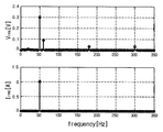
- Figure 8 is the magnitude of the voltage and current according to the frequency processed by using the FFT analysis program using the Matlab which is a waveform analysis method by obtaining the measured injection current and potential waveform
- the present invention relates to an apparatus and method for measuring a composite ground resistance composed of an injection current electrode and a voltage measuring electrode centered on a ground resistance as a midline composite resistance measuring circuit in operation.
- the composite grounding resistor Z N according to the present invention is a value obtained by dividing the selected voltage Vcp by the injection current I inject .
- the apparatus for measuring the neutral composite ground resistance of a distribution line according to the present invention is a 50 Hz, 100 V output voltage and 1.6 kVA for injecting an injection current to measure the neutral composite ground resistance at the neutral composite ground resistance measurement point (the corresponding pole).
- a generator with capacity is provided.
- the generator is provided with an isolation transformer for controlling the magnitude of the injection current, and the voltage adjusting range is provided with a adjusting slack having a voltage range of 0 ⁇ 130 V (continuous) to control the injection current.
- a measuring instrument for measuring the injection current and potential is installed, and an insulating operation rod is designed and manufactured with an insulating material to connect the lead wire for current injection and voltage measurement to the neutral wire, and the lead wire for current injection and voltage measurement is inserted into the rod. It is.
- the method for measuring the neutral composite ground resistance of the distribution line comprises a generator having a 50 Hz, 100 V output voltage and 1.6 kVA capacity, and injecting the injection current through the lead wire of the insulating operation rod at the voltage measurement point It is provided.
- a step for measuring the injection current and the potential using a measuring instrument, and applying the voltage and the injection current measured by the measuring instrument to the Ohm's law consists of a step of calculating the center line composite ground resistance.
- Example 1 relates to an apparatus for measuring a synthetic ground resistance designed and manufactured according to the present invention.
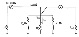
- FIG. 2 is an equivalent circuit of a midline composite ground resistance measuring circuit, and is an explanatory diagram for measuring a midline composite ground resistance composed of an injection current electrode and a voltage measuring electrode based on a ground resistance.
- the midline composite grounding resistor Z N according to the present invention is a value obtained by dividing the selected pole voltage Vcp by the injection current I inject .
- the apparatus for measuring the neutral ground resistance of a neutral conductor of a distribution line according to the present invention has a 50 Hz, 100 V output voltage and 1.6 for injecting an injection current for measuring the neutral ground resistance of a neutral conductor at a measuring point (the corresponding pole).
- a generator with a kVA capacity (1 in FIG. 9) is provided, which corresponds to the AC 100V power supply in FIG.
- An insulation transformer (2 in FIG. 9) is provided for controlling the magnitude of the injection current, and in order to control the injection current, a voltage adjusting range has an adjustment slid (3 in FIG. 9) having 0 to 130 V (continuous). use.
- a measuring instrument (4 in FIG. 9) for measuring the potential and the injection current at the point Vcp in FIG. 2 is fixedly installed.
- An insulating operating rod (6 in FIG. 11) is provided to connect the current injection lead for injecting current into the neutral wire and the voltage measurement lead for measuring the voltage at the Vcp point. That is, the insulation operating rod (6 in FIG. 11) is formed in a structure in which both the current injection lead and the voltage measurement lead wire (5 in FIG. 11) are inserted into the rod of the insulating material, and the lead wire is exposed to the outside. It is configured to be in easy contact with the point.
- Z th is Thevenin's equivalent synthetic impedance in one direction from the measured point of synthetic ground resistance (Z N ), Zn is the midline self impedance, and R ave represents the average value of the ground resistance of each ground point.
- the apparatus for measuring a neutral ground composite ground resistance of a distribution line includes a lead for current injection and voltage measurement, an AC power supply for current injection, and a measuring instrument capable of measuring injection current and measurement voltage.
- the present invention can be manufactured in a small size and light weight in a shape having a display unit for calculating the neutral ground resistance value of the distribution line by calculating based on the measured injection current and voltage.
- a power source consisting of the generator (1 in FIG. 9), the insulation transformer (2 in FIG. 9), and the slides (3 in FIG. 9) is manufactured in a general compact size and widely used.
- the power supply can be configured as a switching mode power supply (SMPS).
- SMPS switching mode power supply
- a power supply for injecting current into the synthetic ground resistance measurement point of the distribution line neutral wire may be able to select and use a desired constant frequency while varying the current and voltage.
- Example 2 according to the present invention relates to a method for measuring the neutral ground composite ground resistance of a distribution line.
- Embodiment 2 according to the present invention relates to a method of calculating in software using a computer equipped with an algorithm according to the present invention or a microprocessor with a built-in memory.
- the first step is to receive the line constant information, grounding information, line distance information, etc. from the new distribution information system (NDIS) to determine the value converged to the simulation (Fig. 4) of the AC circuit formula It is the step of judging applicability.
- NDIS new distribution information system
- FIG. 4 when the right part illustrated by the red line connected up and down to the right part of the center exists as shown in FIG. 4, it is determined to converge.
- the second step is the average value of the ground resistance value (R ave ) and the conductor type of the NDIS within 0.5 km in one direction based on the pole number of NDIS in the equivalent circuit of FIG. 5 centered on the calculated grounding point of the composite ground resistance of the target line.
- Calculate the combined resistance (Z N ) of the neutral wire by applying the value calculated by the neutral circuit self-impedance (Z n ) per 50m distance determined by AC circuit composite resistance (4) to equation (5). It's a step.
- the third step is to minimize the error that occurs in the formula (Z N ) calculation formula of the neutral wire according to the present invention, in order to solve this problem should reflect the potential interference generated during operation, to reflect this
- the distance information between the pole of the point and the voltage auxiliary electrode, the distance information between the measurement ground electrode and the adjacent ground electrode, and other necessary information are inputted.
- the ground resistivity ( ⁇ ) is calculated using the ground resistance inversion method by the rod-type electrode by receiving NDIS information such as individual ground resistance value and ground pole number within a radius of 0.5 km near the measurement pole, and grounding the measurement pole.
- Resistance value (Rg), length of ground electrode (l), ground electrode radius (a), voltage auxiliary electrode length (l ref ), distance between ground electrode and voltage auxiliary electrode (S) of measurement pole, ground electrode It is to derive the integral function constants and variables of the potential influence direction variable z according to the depth of embedding (t) and the depth of embedding to find the potential generated at the electrode.
- the fourth step is to calculate the potential interference coefficient k.
- the third step defines constants and variables for calculating the basic relation (6) of the potential rise (U RO ) by the rod-shaped electrode at any point (x, z) in the ground, and the potential interference coefficient (k). Can be obtained by equation (7).
- the potential rise (U RA ) considering the radius (a) of the measuring point ground electrode is obtained by the formula (8), and the potential rise (U RB) of the voltage auxiliary electrode spaced by the distance S from the measuring point. )
- Equation (7) of the potential interference coefficient k is obtained by dividing the potential rise of the auxiliary electrode by the measurement point ground electrode potential rise.
- the fifth step is a step of calculating the composite ground resistance of the neutral wire reflecting the influence of the potential interference calculated in the fourth step. More specifically, the composite ground resistance Z N of the multi-grounded neutral wire can be calculated by Equation (5) of the second stage, but Equation (5) is the potential of the peripheral ground electrode due to the neutral leakage current in the line in operation. Errors caused by synergistic effects cannot be reflected.
- the actual neutral composite earth resistance in operation more accurately is calculated by the potential rise (U RA ) of the measuring pole by the unit injection current (I), the potential rise of the voltage-assist electrode (U RB ) by the potential interference, and equation (7).
- the potential interference coefficient k thus calculated is accurately calculated by the calculated equation (10).
- the apparatus for measuring the neutral composite ground resistance of a distribution line during operation according to the present invention described in Embodiment 1 is used by using a power source having a frequency of 50 kHz different from a commercial AC power source of 60 kHz to more accurately obtain a neutral composite ground resistance during operation.
- the voltage magnitude is calculated by selecting only the specific frequency potential waveform generated by the injection current using the FFT (fast fourier transform) analysis program using Matlab. It is configured to calculate the neutral ground earth resistance of the distribution line in operation by dividing the divided voltage by the injection current.
- the present invention selects only a specific frequency potential waveform generated by an injection current by programming and mounting an analysis algorithm capable of high-speed processing using a FFT analysis program using a waveform analysis method in a microprocessor equipped with a computer or a memory. Means for calculating the voltage magnitude.
- a specific frequency generated by the injection current waveform using a power source having an oscillation frequency of 50 Hz is used to obtain a more accurate neutral neutral ground resistance in operation.
- the FFT (Fast Fourier Transform) analysis program using Matlab is installed to calculate the potential of the potential, and only the 50 kHz frequency potential waveform generated by the injection current is selected to calculate the voltage magnitude at high speed, and the calculated voltage is converted into the injection current.
- the dividing operation may further include calculating a neutral composite ground resistance of the distribution line.
- the frequency of oscillation in the oscillator is limited to 50 kHz. Since the frequency of the normal AC power supply is 60 kHz, the FFT analysis program using Matlab is installed to obtain the potential waveform of 50 kHz frequency separately from the 60 kHz frequency. This is to obtain the neutral grounding resistance of the distribution line that is operating correctly.
- the 50 kHz frequency may be inputted with a current signal having an arbitrary frequency different from that of the commercial power supply 60 kHz, and analyzed as the input frequency signal.
- the present invention is provided with a power source for injecting a current to the measuring point of the composite ground resistance, and is in operation consisting of a measuring rod for measuring the injection current and the potential and an insulated operating rod for connecting the current supply and voltage measurement lead to the neutral wire
Landscapes
- Physics & Mathematics (AREA)
- General Physics & Mathematics (AREA)
- Measurement Of Resistance Or Impedance (AREA)
Abstract
본 발명은 측정지점에 전류를 주입하기 위하여 전류 크기를 가변할 수 있는 교류전원을 구비하고, 주입전류와 전압측정을 위한 계측기와 중성선에 전류공급용 및 전압측정용 리드선을 접속하기 위하여 절연조작봉으로 구성된 운전 중인 배전선로의 중성선 합성접지저항 측정방법 및 측정장치에 관한 것이다.
Description
본 발명은 중성선 합성접지저항의 측정지점에 전류를 주입하기 위하여 전류 크기를 가변할 수 있는 교류전원을 구비하고, 주입전류와 전위를 측정하기 위한 계측기와 중성선에 전류공급용 및 전압측정용 리드선을 접속하기 위하여 절연조작봉으로 구성된 운전 중인 배전선로의 중성선 합성접지저항 측정 방법 및 그 측정 장치에 관한 것이다.
종래 다중접지 배전계통에서 접지저항을 측정하는 방법은 전위강하법으로 측정대상 접지전극(E)에서 전류 보조극(C)을 멀리 설치하고, 전압보조극(P)을 이동시키면서 거리별 저항분포곡선(도 2)을 그려 분포곡선에서 수평을 이루는 부분의 측정결과가 접지저항 값으로 결정된다. 이 방법은 측정대상 접지전극은 반드시 타 접지시설과는 분리되어야 측정이 가능하므로 운전 중인 배전선로에 적용하기 곤란한 문제점이 있다.
또 다른 방법은 다중접지(각 접지저항 Rk)된 시스템에서 특수한 변류기를 사용하여 측정대상 접지전극(Rx) 회로에 전압 E를 공급해주면 전류 I가 흐르게 되고 다시 변류기를 사용하여 흐르는 전류를 측정할 때 전류와 전압과의 관계가 수식 1과 같이 성립된다(도 1참조).

일반적으로 식(1)에서 Rx가 뒷부분보다 훨씬 크므로, E/I = Rx 라는 식이 성립되어 측정대상 접지전극의 접지저항 값을 측정할 수 있다. 그러나 이러한 방법은 작업자가 측정 가능하도록 접지선이 배전전주 외부로 노출되어 있거나, 활선차를 이용하여 중성선 부근까지 접근하여 측정하게 됨으로 시간, 인력 소요 및 안전사고의 위험이 있고, 정확도가 떨어지는 문제점이 있다.
최근에 종래의 기술을 보완하여 여러 가지 발명이 이루어졌으나, 공통된 제약은 개별접지저항을 측정하기 위하여 발명되었다는 점이다. 이들은 중성선 다중접지 배전계통에서 중성선의 접지시설기준이 km 당 합성저항 값으로 관리됨에도 불구하고 현실적으로 합성저항을 측정할 수 있는 방법이 없고, 종래의 방식을 이용하여 개별저항 값을 측정하여 수식에 의한 계산치로 시공 및 관리되어 과다한 공사비와 관리비용이 발생되고 있다.
또한, 종래의 방식은 근본적으로 중성선 합성접지저항 값을 정확하게 측정할 수 없으며, 계산방식에 있어서도 일반적인 직류회로의 병렬 합성저항 계산식을 이용하고 있기 때문에 실제 값과는 많은 오차가 발생할 수밖에 없다. 이러한 오차는 일반적으로 수 십 개소 이상의 합성 접지저항 값이므로 개별 접지저항 값은 큰 변동 범위를 가지게 되어 개별 접지저항 값을 관리하고 있는 현행기준 하에서는 불필요한 시공 및 관리비용이 발생하는 문제점이 있다.
또 다른 종래기술로 등록특허공보 제10-0445755호에 개시된 측정방법은 측정저항 Rx를 중심으로 좌측 및 우측의 저항 값을 거의 영(0)으로 가정하여 개별접지저항(Rx) 값을 측정하는 것이며, 등록특허공보 제10-0734821호에서는 보조전극의 전위간섭 영향에 대한 오차를 고려하지 않으므로 이들 모두 정확한 중성선 합성접지저항을 구할 수 없는 문제점이 있다.
본 발명이 해결하려는 과제는 수내지 수십 km에 이르는 운전 중인 다중접지 배전선로의 합성저항을 정확하게 측정하여 접지지점을 최소 개소로 설치하여 효율적으로 관리하여 설치 및 유지비용을 절감하는데 있다.
본 발명이 해결하려는 또 다른 과제는 전주와 전압보조전극사이의 거리에 따라서 변환하는 전위간섭계수를 측정하여 이를 연산 알고리즘에 적용하여 측정오차를 최소화함으로써 효율적인 접지시공이 가능하여 배전선로 설치 및 유지비용을 크게 절감하는데 있다.
본 발명이 해결하려는 또 다른 과제는 중성선 합성접지저항 측정지점에 전류를 주입할 때 상용 교류전원의 60㎐ 주파수와 상이한 전류신호를 주입하고, FFT를 Matlab을 이용하여 주입전류에 의해 발생된 특정주파수 전위 파형만을 선택하여 전압을 계산함으로써 정확하게 운전 중인 다중접지 배전선로 중성선 합성접지저항을 얻는데 있다.
본 발명 과제의 해결 수단은 중성선 합성접지저항 측정지점에 전류를 주입하기 위하여 전류와 전압의 크기를 변환할 수 있는 교류전원을 구비하고, 주입전류와 전위측정하기 위한 계측기와 중성선에 전류공급용 및 전압측정용 리드선을 접속하기 위하여 절연조작봉으로 구성된 운전 중인 배전선로의 중성선 합성접지저항 측정장치를 제공하는 것이다.
본 발명 또 다른 과제의 해결 수단은 중성선 합성접지저항 측정지점에 전류를 주입하기 위하여 전류와 전압의 크기를 변환할 수 있는 교류전원을 구비하고, 전압측정지점에 전류를 절연조작봉의 리드선을 통해서 주입하는 단계와, 계측기를 이용하여 주입전류와 전위를 측정하는 단계와, 계측기로 측정한 전압 크기와 주입 전류를 이용하여 리액턴스를 계산하는 단계로 이루어진 운전 중인 배전선로의 중성선 합성접지저항 측정방법을 제공하는 것이다.
본 발명 또 다른 과제의 해결 수단은 주입전류 및 전위의 측정을 위해 전류보조전극(R_c)과 전위보조전극(R_v)이 회로에 포함되고, 전주와 전압보조전극사이의 거리에 따라서 변화하는 전위간섭계수를 측정하여 이를 연산 알고리즘에 적용하여 측정오차를 최소화할 수 있는 운전 중인 배전선로의 중성선 합성접지저항을 측정장치를 제공하는 것이다.
상기 전위간섭계수(K)는 식(2)에 의하여 계산할 수 있다.
K = URB(보조전극의 전위상승)/URA(측정점접지전극의 전위상승) (2)
본 발명 또 다른 과제의 해결 수단은 중성선 합성접지저항 측정지점에 전류를 주입할 때 상용 교류전원의 60㎐ 주파수와 상이한 전류신호를 주입하고, FFT를 Matlab을 이용하여 주입전류에 의해 발생된 특정주파수 전위 파형만을 선택하여 전압을 계산함으로써 정확한 중성선 합성접지저항을 얻을 수 있는 운전 중인 배전선로의 중성선 합성접지저항 측정장치를 제공하는 것이다.
본 발명은 수내지 수십 km에 이르는 운전 중인 다중접지 배전선로의 합성저항을 정확하게 측정하여 접지지점을 최소 개소로 설치하여 효율적으로 관리하여 설치 및 유지비용을 절감할 수 있는 유리한 효과가 있다.
본 발명의 또 다른 효과는 전주와 전압보조전극사이의 거리에 따라 변환하는 전위간섭계수를 측정하여 이를 연산 알고리즘에 적용하여 측정오차를 최소화함으로써 효율적인 접지시공이 가능하여 배전선로 설치 및 유지비용을 크게 절감하는데 있다.
본 발명의 또 다른 효과는 중성선 합성접지저항의 측정값의 정확도를 향상시키기 위하여 보조전극의 위치에 따른 보정계수 산출 수단을 개발 적용하여 측정오차를 최소화하는데 있다.
본 발명의 또 다른 효과는 중성선 합성접지저항 측정지점에 전류를 주입할 때 상용교류전원의 60㎐ 주파수와 상이한 전류를 주입하고, FFT를 Matlab을 이용하여 주입전류에 의해 발생된 특정주파수 전위 파형만을 선택하여 전압을 계산함으로써 정확한 중성선 합성접지저항을 얻는데 있다.
도 1은 종래의 접지저항을 계산할 때 적용된 회로도(식(1))
도 2는 접지저항을 중심으로 주입전류전극 및 전압측정전극으로 구성된 합성접지저항 측정회로 설명도
도 3은 본 발명에 따라 선로정수, 접지 및 선로거리 정보를 입력받아서 수렴여부를 판단할 때 사용된 회로모델
도 4는 시뮬레이션에 의한 합성임피던스가 수렴되는 선로거리를 도시한 도면
도 5는 전주접지점의 접지저항(Rg)과 측정지점에서 양쪽 방향의 테브난 등가 합성임피던스(Zth)를 도시한 회로도
도 6은 배전선로의 중성선 합성접지저항의 측정방법의 흐름도
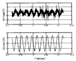
도 7은 측정된 주입전류 및 전위 파형
도 8은 측정된 주입전류 및 전위 파형을 취득하여 파형분석 방법인 Matlab을 이용한 FFT 해석프로그램을 이용하여 처리한 주파수에 따른 전압 및 전류의 크기
도 9는 본 발명의 알고리즘을 적용하여 계산된 전압, 전류 및 저항 값을 보여주는 모니터 화면을 캡쳐한 도면
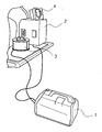
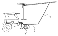
도 10, 도 11은 실제 현장에서 본 발명을 실시하는 모습을 촬영한 사진
본 발명을 실시하기 위한 구체적인 내용을 살펴본다. 본 발명은 운전 중인 중선선 합성저항 측정회로로 접지저항을 중심으로 주입전류전극 및 전압측정전극으로 구성된 합성접지저항 측정장치 및 방법에 관한 것이다.
본 발명에 따른 합성접지저항(ZN)은 선택된 전주의 전압(Vcp)을 주입전류(Iinject)로 나눈 값이다. 본 발명에 따른 배전선로의 중성선 합성접지저항의 측정장치는 중성선 합성접지저항 측정지점(해당 전주)에 중성선 합성접지저항을 측정하기 위하여 주입전류를 주입하기 위하여 50 Hz, 100 V 출력전압 및 1.6 kVA 용량을 가진 발전기를 구비한다.
상기 발전기는 주입전류의 크기를 제어하기 위한 절연변압기를 구비하며, 주입전류를 제어하기 위하여 전압조정범위는 0 ~ 130 V(연속)를 가진 조정용 슬라이닥스를 구비한다.
주입전류와 전위를 측정하기 위한 계측기가 설치되며, 중성선에 전류주입용 및 전압측정용 리드선을 접속하기 위하여 절연재질로 절연조작봉이 설계 제작되고, 전류주입용 및 전압측정용 리드선이 봉 내부에 삽입되어 있다.
또한, 본 발명에 따른 배전선로의 중성선 합성접지저항 측정방법은 50 Hz, 100 V 출력전압 및 1.6 kVA 용량을 가진 발전기를 구비하고, 전압측정지점에 절연조작봉의 리드선을 통해서 주입전류를 주입하는 단계를 구비한다.
또한, 계측기를 이용하여 주입전류와 전위를 측정하기 위한 단계를 구비하며, 계측기로 측정한 전압과 주입 전류를 옴 법칙에 적용하여 중선선 합성접지저항을 계산하는 단계로 이루어진다.
본 발명의 구체적인 실시 예를 살펴본다.
<실시 예>
<실시 예1>
본 발명에 따른 구체적인 실시 예1을 도면에 기초하여 살펴본다. 실시 예1에서는 본 발명에 따라 설계 제작된 합성접지저항의 측정 장치에 관한 것이다. 도 2는 중선선 합성접지저항 측정회로의 등가회로이며, 접지저항을 중심으로 주입전류전극 및 전압측정전극으로 구성된 중선선 합성접지저항 측정을 위한 설명도이다.
도 2에서, 본 발명에 따른 중선선 합성접지저항(ZN)은 선택된 전주의 전압(Vcp)을 주입전류(Iinject)로 나눈 값이다. 이 값을 얻기 위한 본 발명에 따른 배전선로의 중성선 합성접지저항의 측정장치는 측정지점(해당 전주)에 중성선 합성접지저항을 측정하기 위한 주입전류를 주입하기 위하여 50 Hz, 100 V 출력전압 및 1.6 kVA 용량을 가진 발전기(도9의 1)를 구비하며, 이는 도 2의 AC 100V 전원에 해당한다.
상기 주입전류의 크기를 제어하기 위한 절연변압기(도9의 2)를 구비하며, 주입전류를 제어하기 위하여 전압조정범위는 0 ~ 130 V(연속)를 가진 조정용 슬라이닥스(도9의 3)를 사용한다.
도 2의 Vcp 점에서의 전위 및 주입전류를 측정하기 위한 계측기(도9의 4)가 고정 설치된다. 상기 Vcp 점에 접속되어 중성선에 전류를 주입하기 위한 전류주입용 리드선과 Vcp 점의 전압을 측정하기 위한 전압측정용 리드선을 접속하기 위하여 절연조작봉(도 11의 6)을 구비한다. 즉 상기 절연조작봉(도 11의 6)은 전류주입용 및 전압측정용 리드선(도 11의 5) 모두가 절연재질의 봉 내부에 삽입되고, 상부에 리드선이 외부로 노출된 구조로 형성하여 Vcp 점에 용이하게 접촉할 수 있도록 구성되어 있다.
도 2에서, 발전기(도9의 1)를 통해서 입력되는 합성접지저항 측정점인 전주(Vcp)에 주입되는 주입전류 값을 알고, 상기 전압측정용 리드선으로부터 입력되는 Vcp 점에서 측정된 전압을 얻을 경우에 측정된 전압을 주입전류로 나누어 합성접지저항을 계산할 수 있다.
도 2에서, 합성접지저항(ZN)은 Rg와 Zth/2와 병렬로 구성되어 있음을 알 수 있다. Zth 는 식(3)과 같이 표현된다.
Zth = Zn +(Rave//Zth) => (3)
(3)
식(3)에서 Zth는 합성접지저항(ZN) 측정지점에서 한쪽 방향의 테브난 등가 합성임피던스이며, Zn 은 중선선 자체임피던스이고, Rave 는 각 접지점의 접지저항의 평균값을 나타낸다.
본 발명에 따른 배전선로의 중성선 합성접지저항의 측정장치는 전류주입용 및 전압측정용 리드선을 구비하고, 전류주입을 위한 교류전원을 구비하며, 주입전류와 측정전압을 측정할 수 있는 계측기를 구비하고, 측정된 주입전류 및 전압에 기초하여 연산하여 배전선로의 중성선 합성접지저항 값을 표시하는 표시부를 구비한 형상으로 소형ㆍ경량으로 제작할 수 있다.
소형ㆍ경량화를 위한 하나의 예로, 상기 발전기(도9의 1), 절연변압기(도9의 2) 및 슬라이닥스(도9의 3)로 구성되는 전원은 통상의 소형ㆍ경향으로 제작되어 널리 사용되는 전원으로 SMPS(switching mode power supply) 등으로 구성할 수 있다. 본 발명에 따라 배전선로 중성선의 합성접지저항 측정지점에 전류를 주입하기 위한 전원은 전류와 전압을 가변할 수 있으면서 원하는 일정한 주파수를 선택 사용할 수 있는 것이면 족하다.
<실시 예2>
본 발명에 따른 실시 예2는 배전선로의 중성선 합성접지저항의 측정방법에 관한 것이다. 본 발명에 따른 실시 예2는 본 발명에 따른 알고리즘을 탑재한 컴퓨터 또는 메모리가 내장된 마이크로프로세서 등을 이용하여 소프트웨어적으로 계산하는 방법에 관한 것이다.
제1 단계는 NDIS(new distribution information system, 한전배전업무시스템)으로부터 선로정수정보, 접지정보, 선로거리정보 등을 입력받아서 시뮬레이션을 수행하여 어느 값으로 수렴되는지 판정하여(도 4) 교류회로 계산식의 적용가능성을 판단하는 단계이다. 도 4에서 중앙의 우측 부분에 상하로 연결된 붉은 선으로 도시한 우측 부분이 도 4와 같이 존재할 때 수렴하는 것으로 판단한다.
도 3은 본 발명에 따라 상기 수렴여부를 판단할 때 사용된 회로모델이며, 판단 결과 수렴한다고 판단될 경우에 본 발명에 따라 설계된 교류회로 계산식 프로그램으로 중성선 합성접지저항을 계산한다.
제2 단계는 대상선로의 합성접지저항 계산지점을 중심으로 한 도 5의 등가회로에서 NDIS의 전주번호를 기준으로 한쪽 방향으로 0.5 km이내 접지저항 값의 평균값(Rave)과 NDIS의 상도체 선종에 의해 결정되는 1전주간의 거리 50 m 당 중성선 자체임피던스(Zn)을 교류회로 합성저항 계산식(4)에 의해 계산된 값을 식(5)에 적용하여 중성선의 합성저항(ZN)을 계산하는 단계이다.
Zth = Zn +(Rave//Zth) =>  (4)
(4)
ZN = Rg//Zth/2 (5)
제3 단계는 본 발명에 따른 중성선의 합성저항(ZN) 계산식에서 발생하는 오차를 최소화하기 위한 단계이고, 이를 해결하기 위하여서는 운전 중에 발생하는 전위간섭을 반영하여야 하며, 이를 반영하기 위하여 측정 대상지점의 전주와 전압보조전극사이의 거리정보, 측정대상접지전극과 인근접지전극사이의 거리정보 및 기타 필요한 정보를 입력하는 것이다.
보다 구체적으로, 측정전주 인근 반경 0.5 km이내 개별 접지저항 값 및 접지 극 수 등의 NDIS 정보를 입력받아서 봉형전극에 의한 접지저항 역산법을 이용하여 대지저항율(ρ)을 산출하고, 측정전주의 접지저항 값(Rg), 전주 접지전극의 길이(l), 접지전극 반경(a), 전압보조전극 길이(lref), 측정전주의 접지전극과 전압보조전극과의 거리(S), 접지전극의 매설깊이(t), 전극에 발생되는 전위를 구하기 위한 매설 깊이에 따른 전위영향 방향변수(z)의 적분함수 상수 및 변수를 도출하는 것이다.
제4 단계는 전위간섭 계수(k)를 연산하는 단계이다. 제3 단계에 의해 지중의 임의의 점(x, z)에서의 봉형전극에 의한 전위상승(URO)의 기본 관계식 (6)을 계산하기 위한 상수 및 변수를 정의하고, 전위간섭 계수(k)는 수학식 (7)에 의하여 구할 수 있다. 수학식 (7)에서, 측정지점 접지전극의 반경(a)을 고려한 전위상승(URA)은 계산식 (8)에 의하여 구하고, 측정지점에서 거리 S 만큼 이격된 전압보조전극의 전위상승(URB)은 계산식 (9)에 의하여 계산할 수 있다. 전위간섭 계수(k)의 식 (7)은 보조전극의 전위상승분을 측정점 접지전극전위상승분으로 나눈 값이다.
[규칙 제26조에 의한 보정 20.01.2011]
 (6)
(6)
K = URB(보조전극의 전위상승)/URA(측정점접지전극의 전위상승) (7)
[규칙 제26조에 의한 보정 20.01.2011]
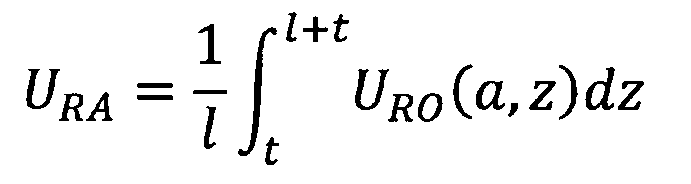 (8)
(8)
[규칙 제26조에 의한 보정 20.01.2011]
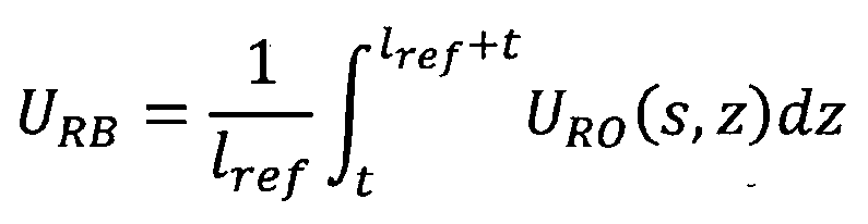 (9)
(9)
제5 단계는 제4 단계에서 연산한 전위간섭 영향을 반영한 중성선의 합성접지저항을 계산하는 단계이다. 보다 구체적으로, 다중 접지된 중성선의 합성접지저항(ZN)은 제2 단계의 식 (5)에 의해 계산할 수 있지만, 식 (5)은 운전 중인 선로에서 중성선 누설전류에 의한 주변 접지전극의 전위상승 영향으로 발생되는 오차 등은 반영할 수 없다.
보다 정확한 운전 중인 실제 중성선 합성접지저항은 단위 주입전류(I)에 의한 측정전주의 전위상승(URA), 전위간섭에 의한 전압보조전극의 전위상승(URB) 및 식 (7)에 의하여 연산된 전위간섭 계수(k)가 반영된 계산식 (10)에 의해 정확하게 계산된다.
ZN_real = VN_real/I = ZN - URB/I = ZN - kURA/I (10)
실시 예1에 설명한 본 발명에 따른 운전 중 배전선로의 중성선 합성접지저항의 측정장치는 보다 정확하게 운전 중 중성선 합성접지저항을 얻기 위하여 상용교류전원 60 ㎐ 주파수와 상이한 50 ㎐ 주파수를 가진 전원을 사용하여 주입 전류파형에 의해 발생된 특정주파수의 전위만을 측정 사용하기 위하여 Matlab을 이용한 FFT(fast fourier transform) 해석프로그램을 이용하여 주입전류에 의해 발생된 특정주파수 전위 파형만을 선택하여 전압 크기를 계산하고, 계산된 전압을 주입전류로 나누어 운전 중인 배전선로의 중성선 합성접지저항을 연산하도록 구성되어 있다.
본 발명에서는 컴퓨터 또는 메모리가 탑재된 마이크로프로세서에 파형분석 방법인 Matlab을 이용한 FFT 해석프로그램을 이용하여 고속 처리할 수 있는 분석 알고리즘을 프로그래밍화하여 탑재시켜 주입전류에 의해 발생된 특정주파수 전위 파형만을 선택하여 전압크기를 연산하는 수단을 구비하고 있다.
보다 구체적으로, 실시 예2의 제4 단계에서, 보다 정확한 운전 중인 중성선 합성접지저항을 얻기 위하여 발진된 50 ㎐의 교류주파수를 가진 전원을 사용하여 주입 전류파형에 의해 발생된 특정주파수인 50 ㎐에 대한 전위만을 계산하기 위하여 Matlab을 이용한 FFT(fast fourier transform) 해석프로그램을 탑재하고, 주입전류에 의하여 발생된 50 ㎐ 주파수 전위 파형만을 선택하여 고속으로 전압 크기를 계산하고, 계산된 전압을 주입전류로 나누어 배전선로의 중성선 합성접지저항을 연산하는 단계를 더 포함할 수 있다.
여기서, 발진기에서 발진하는 주파수를 50㎐로 한정한 것은 통상의 교류전원의 주파수가 60㎐이므로 Matlab을 이용한 FFT 해석 프로그램을 탑재하여 60 ㎐ 주파수와 구분하여 50㎐ 주파수의 전위파형을 얻어서 보다 신속하고 정확하게 운전 중인 배전선로의 중성선 합성접지저항을 얻기 위한 것이다. 여기서, 50㎐ 주파수는 상용전원 60㎐와 상이한 임의의 주파수를 가진 전류신호를 입력하고, 입력된 주파수 신호로 분석할 수 있다.
본 발명은 합성접지저항 측정지점에 전류를 주입하기 위한 전원을 구비하고, 주입전류와 전위를 측정하기 위한 계측기와 중성선에 전류공급용 및 전압측정용 리드선을 접속하기 위하여 절연조작봉으로 구성된 운전 중인 배전선로의 중성선 합성접지저항 측정방법 및 측정장치를 제공하여 보다 정확한 합성접지저항을 측정하여 접지지점을 최소 개소로 설치하여 효율적으로 관리하여 설치 및 유지비용을 절감할 수 있음으로써 산업상 이용가능성이 매우 높다.
Claims (9)
- 운전 중인 배전선로의 중성선 합성접지저항 측정장치에 있어서,배전선로의 중선선 합성접지저항 측정지점에 전류를 주입하기 위한 교류전원;상기 배전선로의 중선선 합성접지저항 측정지점의 주입전류와 전위를 측정하기 위한 계측기;상기 중성선 합성접지저항 측정지점에 교류 전류를 주입하기 위한 전류공급용 리드선;상기 배전선로의 중선선 합성접지저항 측정지점의 전압을 측정하기 위한 전압측정용 리드선; 및상기 측정지점에서 측정한 전압을 교류전원에서 주입한 주입전류로 나누어 중성선 합성접지저항을 구하는 것을 특징으로 하는 운전 중인 배전선로의 중성선 합성접지저항 측정장치.
- 청구항 1에 있어서,상기 계측기에 의하여 측정된 주입전류와 측정된 전압을 입력받아서 운전 중인 배전선로의 중성선 합성접지저항을 연산하는 컴퓨터 또는 메모리가 탑재된 마이크로프로세서를 더 구비한 운전 중인 배전선로의 중성선 합성접지저항 측정장치.
- 청구항 2에 있어서,상기 컴퓨터 또는 메모리에 Matlab을 이용한 FFT 해석프로그램을 탑재하고,운전 중인 배전선로의 중성선 합성접지저항을 정확하게 측정하기 위하여 상기 중성선 합성접지저항 측정지점에 전류를 주입하기 위한 교류전원을 상용전원의 60㎐ 주파수와 상이한 전류를 주입하고, 상기 Matlab을 이용한 FFT 해석프로그램을 이용하여 주입전류에 의해 발생된 특정주파수 전위 파형만을 선택하여 전압을 계산함을 특징으로 하는 운전 중인 배전선로의 중성선 합성접지저항 측정장치.
- 청구항 1내지 청구항 3 중 어느 한 항에 있어서,상기 전류공급용 및 전압측정용 리드선은 절연재질의 하나의 봉 내부에 전류공급용 및 전압측정용 리드선이 삽입되고, 리드선을 중성선 합성접지저항 측정지점에 용이하게 접촉시킬 수 있도록 봉의 상부에 리드선이 노출된 형상으로 이루어진 운전 중인 배전선로의 중성선 합성접지저항 측정장치.
- 운전 중인 배전선로의 중성선 합성접지저항 측정방법에 있어서,배전선로의 중성선 전압측정지점에 교류전원을 통해서 전류를 절연조작봉의 리드선을 통해서 주입하는 단계;계측기를 이용하여 배전선로의 중성선 전압측정지점에 주입전류와 전위를 측정하는 단계; 및상기 계측기로 배전선로의 중성선 전압측정지점에서 측정한 전압과 주입전류를 이용하여 옴의 법칙으로 중성선 합성접지저항을 계산하는 단계로 이루어진 운전 중인 배전선로의 중성선 합성접지저항 측정방법.
- 운전 중인 배전선로의 중성선 합성접지저항 측정방법에 있어서,NDIS로부터 선로정수, 접지정보, 선로거리 정보를 입력받아서 시뮬레이션을 수행하여 수렴 여부를 판정하는 제1단계; 및상기 제1 단계에서 수렴되는 것으로 판정되면 NDIS의 전주번호를 기준으로 한쪽 방향으로 0.5 km이내 접지저항 값의 평균값과 NDIS의 상도체 선종에 의해 결정되는 중성선 자체임피던스를 이용하여 중성선의 합성저항(ZN)을 계산하는 제2 단계로 이루어진 운전 중인 배전선로의 중성선 합성접지저항 측정방법.
- 알고리즘을 탑재한 컴퓨터 또는 메모리가 내장된 마이크로프로세서를 이용하여 운전 중인 배전선로의 중성선 합성접지저항 측정방법에 있어서,NDIS로부터 선로정수, 접지정보, 선로거리 정보를 입력받아서 시뮬레이션을 수행하여 수렴 여부를 판정하는 제1단계;상기 제1 단계에서 수렴되는 것으로 판정되면, NDIS의 전주번호를 기준으로 한쪽 방향으로 0.5 km이내 접지저항 값의 평균값과 NDIS의 상도체 선종에 의해 결정되는 중성선 자체임피던스를 이용하여 중성선의 합성저항(ZN)을 계산하는 제2 단계;운전 중에 발생하는 전위간섭을 반영하기 위하여 측정 대상지점의 전주와 전압보조전극사이의 거리정보, 측정대상접지전극과 인근접지전극사이의 거리정보를 입력하는 제3 단계;전압보조전극의 전위상승분을 측정지점 접지전극전위상승분으로 나눈 운전 중인 배전선로의 중성선의 전위간섭 계수(k)를 구하는 제4 단계; 및상기 제4 단계에서 연산된 운전 중인 배전선로의 중성선의 전위간섭 계수(k)를 이용하여 중성선의 합성저항을 계산하는 제5 단계로 이루어진 운전 중인 배전선로의 중성선 합성접지저항 측정방법.
- 청구항 7에 있어서,상기 제4 단계는 컴퓨터 또는 메모리에는 전압보조전극의 전위상승분과 측정지점 접지전극전위상승분을 연산하는 알고리즘을 탑재하고,상기 연산된 전압보조전극의 전위상승분(URB)을 측정지점 접지전극 전위상승분(URA)으로 나누어 운전 중인 배전선로의 중성선의 전위간섭 계수(k)를 구하며,중성선의 합성저항(ZN) 값에서 전압보조전극의 전위상승분(URB)을 주입전류로 나눈 값을 뺀 값으로 중성선 합성접지저(ZN-real)항을 측정하는 단계가 포함된 운전 중인 배전선로의 중성선 합성접지저항 측정방법.
- 청구항 7 또는 청구항 8에 있어서,상기 제4 단계에서, 컴퓨터 또는 마이크로프로세서에 탑재된 메모리에 Matlab을 이용한 FFT 해석프로그램을 탑재하고,운전 중인 배전선로의 중성선 합성접지저항을 정확하게 측정하기 위하여 상기 중성선 합성접지저항 측정지점에 전류를 주입하기 위한 교류전원을 상용전원의 60㎐ 주파수와 상이한 전류를 주입하며,상기 Matlab을 이용한 FFT 해석프로그램을 이용하여 주입전류에 의해 발생된 특정주파수 전위 파형만을 선택하여 전압을 계산함을 특징으로 하는 운전 중인 배전선로의 중성선 합성접지저항 측정방법.
Applications Claiming Priority (2)
| Application Number | Priority Date | Filing Date | Title |
|---|---|---|---|
| KR1020100072865A KR101061447B1 (ko) | 2010-07-28 | 2010-07-28 | 운전 중인 배전선로의 중성선 합성접지저항 측정방법 및 장치 |
| KR10-2010-0072865 | 2010-07-28 |
Publications (1)
| Publication Number | Publication Date |
|---|---|
| WO2012015107A1 true WO2012015107A1 (ko) | 2012-02-02 |
Family
ID=44956798
Family Applications (1)
| Application Number | Title | Priority Date | Filing Date |
|---|---|---|---|
| PCT/KR2010/008338 Ceased WO2012015107A1 (ko) | 2010-07-28 | 2010-11-24 | 운전 중인 배전선로의 중성선 합성접지저항 측정방법 및 장치 |
Country Status (2)
| Country | Link |
|---|---|
| KR (1) | KR101061447B1 (ko) |
| WO (1) | WO2012015107A1 (ko) |
Cited By (4)
| Publication number | Priority date | Publication date | Assignee | Title |
|---|---|---|---|---|
| CN103487836A (zh) * | 2013-10-11 | 2014-01-01 | 钟世航 | 一种电法勘探的多电极多个供电单元系统及其勘探方法 |
| CN107656144A (zh) * | 2017-11-14 | 2018-02-02 | 国网山东省电力公司电力科学研究院 | 一种输电线路接地系统的综合检测系统及方法 |
| CN115561526A (zh) * | 2022-11-08 | 2023-01-03 | 国网电力科学研究院有限公司 | 一种电缆导体交流电阻测试装置及方法 |
| CN116879635A (zh) * | 2023-07-27 | 2023-10-13 | 中国南方电网有限责任公司超高压输电公司广州局 | 共用接地极电阻监测方法、装置、设备、存储介质和产品 |
Families Citing this family (5)
| Publication number | Priority date | Publication date | Assignee | Title |
|---|---|---|---|---|
| CN113899985B (zh) * | 2021-09-29 | 2024-03-26 | 国网重庆市电力公司璧山供电分公司 | 一种配电线路接地线状态智能检测方法 |
| CN114498558B (zh) * | 2022-01-12 | 2023-10-24 | 中国长江电力股份有限公司 | 基于20Hz电流电压相位差的发电机定子接地电阻分段算法 |
| KR102789672B1 (ko) | 2022-11-11 | 2025-04-03 | 한국전력공사 | 다중접지된 중성선의 합성 접지저항 측정 방법 및 장치 |
| KR102561626B1 (ko) | 2023-02-02 | 2023-07-31 | 에스엠인스트루먼트 주식회사 | 활선선로의 전류 및 전위 측정을 위한 감지 장치 |
| KR102593291B1 (ko) | 2023-04-04 | 2023-10-24 | 에스엠인스트루먼트 주식회사 | 접지전극의 대지전위를 이용한 활선 상태에서의 접지저항 측정 시스템 및 방법 |
Citations (6)
| Publication number | Priority date | Publication date | Assignee | Title |
|---|---|---|---|---|
| JPH0587847A (ja) * | 1991-04-02 | 1993-04-06 | Touden Sekkei Kk | 接地抵抗の測定方法 |
| KR20010025613A (ko) * | 2001-01-11 | 2001-04-06 | 정재기 | 누설전류를 이용한 활선상태 송전철탑 및 배전전주의접지저항 측정방법 및 장치 |
| KR20020089864A (ko) * | 2001-05-25 | 2002-11-30 | 한국전력공사 | 다중접지계통의 접지저항 자동측정장치 및 그 측정방법 |
| KR20050021668A (ko) * | 2003-08-25 | 2005-03-07 | 한국전력공사 | 운전중인 변전소 접지전류 분류계수 측정 및 접지저항분석시스템 |
| JP2005077316A (ja) * | 2003-09-02 | 2005-03-24 | Chugoku Electric Power Co Inc:The | 電力系統の対地静電容量測定装置 |
| KR20070046645A (ko) * | 2005-10-31 | 2007-05-03 | 한국전력공사 | 운전 중인 송전계통에서 송전철탑의 접지저항 측정방법 |
-
2010
- 2010-07-28 KR KR1020100072865A patent/KR101061447B1/ko not_active Expired - Fee Related
- 2010-11-24 WO PCT/KR2010/008338 patent/WO2012015107A1/ko not_active Ceased
Patent Citations (6)
| Publication number | Priority date | Publication date | Assignee | Title |
|---|---|---|---|---|
| JPH0587847A (ja) * | 1991-04-02 | 1993-04-06 | Touden Sekkei Kk | 接地抵抗の測定方法 |
| KR20010025613A (ko) * | 2001-01-11 | 2001-04-06 | 정재기 | 누설전류를 이용한 활선상태 송전철탑 및 배전전주의접지저항 측정방법 및 장치 |
| KR20020089864A (ko) * | 2001-05-25 | 2002-11-30 | 한국전력공사 | 다중접지계통의 접지저항 자동측정장치 및 그 측정방법 |
| KR20050021668A (ko) * | 2003-08-25 | 2005-03-07 | 한국전력공사 | 운전중인 변전소 접지전류 분류계수 측정 및 접지저항분석시스템 |
| JP2005077316A (ja) * | 2003-09-02 | 2005-03-24 | Chugoku Electric Power Co Inc:The | 電力系統の対地静電容量測定装置 |
| KR20070046645A (ko) * | 2005-10-31 | 2007-05-03 | 한국전력공사 | 운전 중인 송전계통에서 송전철탑의 접지저항 측정방법 |
Cited By (6)
| Publication number | Priority date | Publication date | Assignee | Title |
|---|---|---|---|---|
| CN103487836A (zh) * | 2013-10-11 | 2014-01-01 | 钟世航 | 一种电法勘探的多电极多个供电单元系统及其勘探方法 |
| CN103487836B (zh) * | 2013-10-11 | 2016-06-29 | 钟世航 | 一种电法勘探的多电极多个供电单元系统及其勘探方法 |
| CN107656144A (zh) * | 2017-11-14 | 2018-02-02 | 国网山东省电力公司电力科学研究院 | 一种输电线路接地系统的综合检测系统及方法 |
| CN115561526A (zh) * | 2022-11-08 | 2023-01-03 | 国网电力科学研究院有限公司 | 一种电缆导体交流电阻测试装置及方法 |
| CN116879635A (zh) * | 2023-07-27 | 2023-10-13 | 中国南方电网有限责任公司超高压输电公司广州局 | 共用接地极电阻监测方法、装置、设备、存储介质和产品 |
| CN116879635B (zh) * | 2023-07-27 | 2024-06-04 | 中国南方电网有限责任公司超高压输电公司广州局 | 共用接地极电阻监测方法、装置、设备、存储介质和产品 |
Also Published As
| Publication number | Publication date |
|---|---|
| KR101061447B1 (ko) | 2011-09-02 |
Similar Documents
| Publication | Publication Date | Title |
|---|---|---|
| WO2012015107A1 (ko) | 운전 중인 배전선로의 중성선 합성접지저항 측정방법 및 장치 | |
| CN1748149A (zh) | 用于高压导体的电压测量的方法与装置 | |
| CN108918986B (zh) | 一种低压电力电缆电磁屏蔽性能测试方法和系统 | |
| CN108152596B (zh) | 一种电力杆塔接地电阻测量仪及电阻测量方法 | |
| CN108535598B (zh) | 一种轨道电路电缆故障在线检测方法和装置 | |
| KR20010025613A (ko) | 누설전류를 이용한 활선상태 송전철탑 및 배전전주의접지저항 측정방법 및 장치 | |
| WO2017030284A1 (ko) | 지하 물성 탐사시스템 및 이를 이용한 지하 물성 분석방법 | |
| RU2394250C2 (ru) | Способ и устройство для определения места аварийного заземления | |
| EP3652545A1 (en) | Contactless voltage transducer | |
| KR20220116965A (ko) | 복수의 케이블에 대한 열화 진단 방법 및 복수의 케이블에 대한 열화 진단 장치 | |
| CN109470929A (zh) | 基于物联网的实时接地防雷监测系统与监测方法 | |
| KR102559740B1 (ko) | 부하의 절연저항 측정방법 및 부하의 절연저항 측정장치 | |
| KR102753686B1 (ko) | 철탑용 직류전계 측정 장치 | |
| KR200169790Y1 (ko) | 콘크리트 전주용 접지저항 측정기 | |
| CN118566611A (zh) | 输电线路工频感应参数测量方法、装置、介质和设备 | |
| CN111273070A (zh) | 一种串联式交流高压母线测量装置及方法 | |
| CN111123037A (zh) | 一种配电网故障定点检测装置及检测方法 | |
| ES3040793T3 (en) | System and method for detecting insulation defects in an underground power cable | |
| ES2982936T3 (es) | Sistema para el análisis de la calidad de la potencia y método para la monitorización desde el exterior, de cables multiconductores | |
| WO2018225888A1 (ko) | 철탑 기초 제원 예측 방법 | |
| WO2015072601A1 (ko) | 부분방전 판단 장치 및 방법 | |
| JPH11237426A (ja) | 変圧器の周波数特性測定装置 | |
| Rubinstein et al. | Discussion on the assessment and mitigation of radiation from PLC networks | |
| Zucca et al. | Unperturbed Electric Field and Operator Current Towards Ground in HV Substations: a linear relationship between two measurements | |
| Desideri et al. | MV line electric field evaluation near a concrete pole |
Legal Events
| Date | Code | Title | Description |
|---|---|---|---|
| 121 | Ep: the epo has been informed by wipo that ep was designated in this application |
Ref document number: 10855379 Country of ref document: EP Kind code of ref document: A1 |
|
| NENP | Non-entry into the national phase |
Ref country code: DE |
|
| 122 | Ep: pct application non-entry in european phase |
Ref document number: 10855379 Country of ref document: EP Kind code of ref document: A1 |