WO2012015047A1 - 埋め込み次数1かつ合成数位数の楕円曲線上の有理点のスカラー倍算およびペアリング演算 - Google Patents
埋め込み次数1かつ合成数位数の楕円曲線上の有理点のスカラー倍算およびペアリング演算 Download PDFInfo
- Publication number
- WO2012015047A1 WO2012015047A1 PCT/JP2011/067520 JP2011067520W WO2012015047A1 WO 2012015047 A1 WO2012015047 A1 WO 2012015047A1 JP 2011067520 W JP2011067520 W JP 2011067520W WO 2012015047 A1 WO2012015047 A1 WO 2012015047A1
- Authority
- WO
- WIPO (PCT)
- Prior art keywords
- rational
- storage means
- pairing
- mod
- satisfies
- Prior art date
- Legal status (The legal status is an assumption and is not a legal conclusion. Google has not performed a legal analysis and makes no representation as to the accuracy of the status listed.)
- Ceased
Links
Images






Classifications
-
- G—PHYSICS
- G06—COMPUTING OR CALCULATING; COUNTING
- G06F—ELECTRIC DIGITAL DATA PROCESSING
- G06F7/00—Methods or arrangements for processing data by operating upon the order or content of the data handled
- G06F7/60—Methods or arrangements for performing computations using a digital non-denominational number representation, i.e. number representation without radix; Computing devices using combinations of denominational and non-denominational quantity representations, e.g. using difunction pulse trains, STEELE computers, phase computers
- G06F7/72—Methods or arrangements for performing computations using a digital non-denominational number representation, i.e. number representation without radix; Computing devices using combinations of denominational and non-denominational quantity representations, e.g. using difunction pulse trains, STEELE computers, phase computers using residue arithmetic
- G06F7/724—Finite field arithmetic
- G06F7/725—Finite field arithmetic over elliptic curves
-
- H—ELECTRICITY
- H04—ELECTRIC COMMUNICATION TECHNIQUE
- H04L—TRANSMISSION OF DIGITAL INFORMATION, e.g. TELEGRAPHIC COMMUNICATION
- H04L9/00—Cryptographic mechanisms or cryptographic arrangements for secret or secure communications; Network security protocols
- H04L9/30—Public key, i.e. encryption algorithm being computationally infeasible to invert or user's encryption keys not requiring secrecy
- H04L9/3066—Public key, i.e. encryption algorithm being computationally infeasible to invert or user's encryption keys not requiring secrecy involving algebraic varieties, e.g. elliptic or hyper-elliptic curves
- H04L9/3073—Public key, i.e. encryption algorithm being computationally infeasible to invert or user's encryption keys not requiring secrecy involving algebraic varieties, e.g. elliptic or hyper-elliptic curves involving pairings, e.g. identity based encryption [IBE], bilinear mappings or bilinear pairings, e.g. Weil or Tate pairing
Definitions
- the present invention relates to a scalar multiplication apparatus, a scalar multiplication method, a scalar multiplication program for performing scalar multiplication [s] P of a rational point P, a pairing operation apparatus capable of executing a pairing operation at high speed, and a pair
- the present invention relates to a ring calculation method and a pairing calculation program.
- a scalar multiplication device when the embedding degree of a rational point group is 1, a scalar multiplication device, a scalar multiplication method and a scalar multiplication program for performing scalar multiplication [s] P of a rational point P, and embedding of a rational point group
- the present invention relates to a pairing calculation device, a pairing calculation method, and a pairing calculation program that can execute pairing calculations at high speed when the order is 1.
- authentication processing is required to confirm that the user of the service is an appropriate user, not impersonation or a fictitious person, and a highly reliable authentication method.
- electronic authentication technology based on public key cryptography using a public key and a secret key is often used.
- the authentication device does not authenticate using the user's personal information, but uses multiple users as a group and uses a group signature indicating that they belong to this group.
- a group signature technique has been proposed in which authentication is performed without specifying a person, thereby enabling authentication without accumulating personal information in an authentication apparatus.
- Pairing is a function of two inputs and one output defined on an elliptic curve.
- the input uses two rational points on the elliptic curve and the output uses a finite field element.
- This pairing has bilinearity for two inputs. That is, for example, rational points on an elliptic curve defined with P on prime field F p, as rational points on an elliptic curve defined with Q over k-th extension field F p k, and inputs the P and Q when the original z of the extension field F * p k Te is output, z of ab-th power is outputted by entering the a times of P and b times Q.
- k is referred to as an embedding degree
- F * p k represents a multiplicative group obtained by removing the unit element 0 from a finite field (expanded field) having an order p k .
- Such a pairing calculation of rational points on an elliptic curve is composed of a step of calculating using a Miller algorithm and a step of performing exponentiation on the calculation result.
- encryption / decryption processing using ID-based encryption and authentication processing using group signatures are required to be executed in as short a time as possible.
- encryption method based on pairing and the like a large number of scalar multiplications are performed, so that it is also required to perform the scalar multiplication at high speed.
- Binary methods and window methods are known as methods for speeding up scalar multiplication.
- a method for reducing the number of computations and increasing the speed by using self-homogeneous mapping has been proposed (see, for example, Non-Patent Document 2 and Patent Document 2).
- the conventional techniques for improving the efficiency of pairing ciphers with prime orders are not immediately applicable to the pairing with large composite orders targeted by the present invention.
- the pairing curve of the composite order is placed in a special situation such that the embedding degree is 1, and therefore, it has become necessary to propose a new high-speed method considering this.
- the reason why the embedding order is 1 is that the embedding order is 1 that is most suitable for balancing the strength and efficiency for ensuring the necessary and sufficient encryption strength of the pairing cipher.
- the embedding order is increased, the encryption strength is too high, and the efficiency in realizing it is deteriorated.
- the two rational point subgroups G1 and G2 can be easily identified, so that they can be used for the GLV (Gallant-Lambert-Vanstone) method (scalar multiplication fast Technology) and Xate pairing (speeding up pairing).
- GLV Global-Lambert-Vanstone
- Xate pairing speeding up pairing
- the present inventors improve the practicality by speeding up the scalar multiplication and the pairing operation in the pairing curve with the embedding degree of the rational point group being 1 and a large synthetic order. As a result, research and development have been conducted to achieve the present invention.
- the additive group formed by the rational points on an elliptic curve defined on a finite field F p of characteristic p and E (F p), a set i.e. subgroup of the additive group of rational points with synthetic number digit numbers r G E (F p ) [r], in a scalar multiplication apparatus comprising a CPU and storage means for computing scalar multiplication [s] P with rational points P ⁇ G by integer 0 ⁇ s ⁇ r,
- the additive group E (F p ) has an embedding degree of 1,
- the CPU is Input means for inputting a rational point P′ ⁇ E (F p ) [r] and the integer s and storing them in the storage means;
- the composite order r satisfies r
- the composite order r satisfies r
- the composite order r satisfies r
- the additive group formed by the rational points on an elliptic curve defined on a finite field F p of characteristic p and E (F p), a set i.e. subgroup of the additive group of rational points with synthetic number digit numbers r G E (F p ) [r]
- the additive group E (F p ) has an embedding degree of 1, An input step of causing the CPU of the electronic computer to function as an input means, inputting a rational point P′ ⁇ E (F p ) [r] and the integer s, respectively, and storing them in the storage means;
- the set of rational points P satisfying the self-homogeneous map ⁇ (P) ⁇ P ( ⁇ is an integer) by causing the CPU of
- the composite order r satisfies r
- the composite order r satisfies r
- the composite order r satisfies r
- the additive group formed by the rational points on an elliptic curve defined on a finite field F p of characteristic p and E (F p), a set i.e. subgroup of the additive group of rational points with synthetic number digit numbers r G E (F p ) [r]
- the additive group E (F p ) has an embedding degree of 1, CPU of the computer
- the composite order r satisfies r
- the composite order r satisfies r
- the composite order r satisfies r
- the additive group formed by the rational points on an elliptic curve defined on a finite field F p of characteristic p and E (F p), a set i.e. subgroup of the additive group of rational points with synthetic number digit numbers r
- G 1 E (F p ) [r]
- G 2 E (F p ) [r] e: G 1 ⁇ G 2 ⁇ F * p / (F * p ) r
- pairing e as a non-degenerate bilinear map that is The rational points P (x P , y P ) ⁇ G 1 and Q (x Q , y Q ) ⁇ G 2 , and the rational function calculated using Miller's algorithm as f, the pairing e (P, Q)
- the additive group E (F p ) has an embedding degree of 1,
- the CPU is Input means for inputting
- the composite order r satisfies r
- the f ′ r, p (Q) is It also has a feature.
- the composite order r satisfies r
- the f ′ r, p (Q) is It also has a feature.
- the composite order r satisfies r
- the f ′ r, p (Q) is It also has a feature.
- the additive group formed by the rational points on an elliptic curve defined on a finite field F p of characteristic p and E (F p), a set i.e. subgroup of the additive group of rational points with synthetic number digit numbers r
- G 1 E (F p ) [r]
- G 2 E (F p ) [r] e: G 1 ⁇ G 2 ⁇ F * p / (F * p ) r
- pairing e as a non-degenerate bilinear map that is An electronic computer having a CPU and storage means, with rational points P (x P , y P ) ⁇ G 1 and Q (x Q , y Q ) ⁇ G 2 , and a rational function calculated using the Miller algorithm
- the additive group E (F p ) has an embedding degree of 1, Allowing the CPU of the electronic computer to function as an input means, inputting a rational
- the composite order r satisfies r
- the f ′ r, p (Q) is It also has a feature.
- the composite order r satisfies r
- the f ′ r, p (Q) is It also has a feature.
- the composite order r satisfies r
- the integers ⁇ 1 and ⁇ 2 are ⁇ 1 2 - ⁇ 1 + 1 ⁇ 0 (mod r), ⁇ 2 2 - ⁇ 2 + 1 ⁇ 0 (mod r),
- the f ′ r, p (Q) is It also has a feature.
- the additive group formed by the rational points on an elliptic curve defined on a finite field F p of characteristic p and E (F p), a set i.e. subgroup of the additive group of rational points with synthetic number digit numbers r
- G 1 E (F p ) [r]
- G 2 E (F p ) [r] e: G 1 ⁇ G 2 ⁇ F * p / (F * p ) r
- pairing e as a non-degenerate bilinear map that is An electronic computer having a CPU and storage means, with rational points P (x P , y P ) ⁇ G 1 and Q (x Q , y Q ) ⁇ G 2 , and a rational function calculated using the Miller algorithm
- the additive group E (F p ) has an embedding degree of 1, The CPU of the electronic computer, an input means for inputting a rational point
- the composite order r satisfies r
- the integers ⁇ 1 and ⁇ 2 are ⁇ 1 2 + 1 ⁇ 0 (mod r), ⁇ 2 2 + 1 ⁇ 0 (mod r),
- the f ′ r, p (Q) is It also has a feature.
- the composite order r satisfies r
- the integers ⁇ 1 and ⁇ 2 are ⁇ 1 2 + ⁇ 1 + 1 ⁇ 0 (mod r), ⁇ 2 2 + ⁇ 2 + 1 ⁇ 0 (mod r),
- the f ′ r, p (Q) is It also has a feature.
- the composite order r satisfies r
- the integers ⁇ 1 and ⁇ 2 are ⁇ 1 2 - ⁇ 1 + 1 ⁇ 0 (mod r), ⁇ 2 2 - ⁇ 2 + 1 ⁇ 0 (mod r),
- the f ′ r, p (Q) is It also has a feature.
- the rational function calculated using the Miller algorithm is calculated twice in the pairing operation, but the value obtained in the first half is held in the storage means. By using them efficiently in the latter half of the calculation, the efficiency can be improved by about 30% compared to Tate pairing.
- FIG. 1 It is a schematic diagram which shows schematic structure of the scalar multiplication apparatus or pairing arithmetic unit concerning embodiment of this invention. It is the block diagram which illustrated the whole structure of the scalar multiplication apparatus or pairing arithmetic unit concerning embodiment of this invention. It is the figure which illustrated the functional structure of the rational point subgroup specific
- a pairing curve to which the results of the present invention can be applied must satisfy the following conditions.
- E / F p : y 2 x 3 + ax + b, a ⁇ F p b ⁇ F p
- E (F p): additive group of rational points of the elliptic curve defined on a finite field F p of characteristic p forms, r: E (F p) of order #E (F p) composite number that divides the, E [r]: set of rational points whose order is the composite number r, ⁇ : self-homogeneous mapping for rational points, t: Trace of Frobenius map, [j]: Map that multiplies rational points by j, G: G E [r] ⁇ Ker ( ⁇ ), defined as a set of rational points satisfying ( ⁇ is an integer).
- y represents that x is divisible by y.
- CM Complex Multiplication
- Equation (16) for the 4th order is the same as that for the 3rd order and will not be described.
- Equation (22) for the 6th order is the same as that for the 3rd order and will not be described.
- Equation (26) can be obtained by a multi-scalar multiplication method (see [Table 1]), which will be described later, which is an existing high-speed method for obtaining a scalar multiplication of a plurality of rational points. Since ⁇ 2 ⁇ r and s 0 and s 1 are approximately half the number of bits when the binary expansion is performed, the calculation time is approximately half that of the binary method.
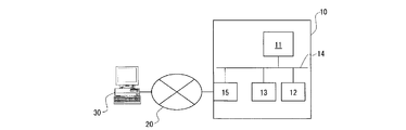
- FIG. 1 is a schematic diagram of a scalar multiplication apparatus according to an embodiment of the present invention.
- FIG. 2 is a block diagram illustrating the overall configuration of the scalar multiplication apparatus according to the embodiment of the invention.
- a program for identifying the above-described rational point subgroup from a given pairing curve when performing authentication processing of a digital group signature by an authentication server configured with a required electronic computer and a general Only the scalar multiplication program part executed as a subroutine process will be described.
- the rational point subgroup identification and scalar multiplication operations are not limited to those performed by the authentication server, and any device having at least an arithmetic means such as a CPU and a storage means may be used. It may be a simple device.
- the electronic computer 10 constituting the authentication server includes a CPU ⁇ 11 that executes arithmetic processing, various programs such as a rational point subgroup specifying program, a scalar multiplication operation program, a pairing operation program, and the like.
- a storage device 12 such as a hard disk that stores data used in the program, and a RAM etc. that can develop and execute these programs and temporarily store the data generated as a result of executing these programs
- a configured memory device 13 is provided.
- 14 is a bus.
- the electronic computer 10 constituting the authentication server is connected to the telecommunication line 20 such as the Internet, and can receive the signature data of the digital group signature transmitted from the client device 30 connected to the telecommunication line 20 (FIG. 2, authentication data input unit 100).
- the electronic computer 10 constituting the authentication server is connected to the telecommunication line 20 such as the Internet, and can receive the signature data of the digital group signature transmitted from the client device 30 connected to the telecommunication line 20 (FIG. 2, authentication data input unit 100).
- 15 is an input / output unit of the electronic computer 10.
- the electronic computer 10 constituting the authentication server when the signature data of the digital group signature is transmitted from the client device 30, the transmitted signature data is temporarily stored in the memory device 13 (authentication data input unit 100), and the rational point portion After starting the group identification program and identifying the rational point subgroup that enables efficient self-homogeneous mapping (Fig. 2, rational point subgroup identification unit 200), the pairing operation program is activated and pairing is started. The calculation is executed (FIG. 2, pairing calculation unit 300). Then, in the electronic computer 10 constituting the authentication server, when a required scalar multiplication operation is necessary for executing the pairing operation, the scalar multiplication operation program is started and the scalar multiplication is executed. (FIG. 2, scalar multiplication unit 400). Thereafter, the authentication result is output (FIG. 2, authentication result output unit 500).
- FIG. 3 is a diagram illustrating a functional configuration of a rational point subgroup specifying unit realized by executing a predetermined program by the apparatus shown in FIG.
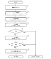
- FIG. 4 is a flowchart of a rational point subgroup specifying program that performs processing of the rational point subgroup specifying unit.
- the electronic computer 10 a rational point subgroup that enables efficient self-homogeneous mapping is specified based on the flowchart shown in FIG. That is, the input rational point group is converted into a rational point in a specific rational point subgroup.
- the electronic computer 10 functions as a rational point subgroup specifying means.
- the case of the third-order GLV method will be described.
- step T1 a general rational point P ′ given from the outside and stored in the storage means by the input means is read.
- step T2 constant operation unit 220
- ⁇ 2 + ⁇ + 1 ⁇ 0 (mod r) shown in Expression (3) is obtained by using the characteristic p and finite number r of the finite field stored in the register in advance.
- ⁇ and ⁇ ( ⁇ 1) that satisfies ⁇ 3 ⁇ 1 (mod p) shown in Expression (4b) are calculated and set.
- step T3 self-homogeneous mapping operation unit 230
- the x coordinate value x of P ′ is multiplied by ⁇ as ⁇ (P ′) :( x, y) ⁇ ( ⁇ x, y) in equation (4b), and ⁇ Seeking (P ').
- step T4 rational point calculation unit 240
- P ⁇ (P ′) + ( ⁇ + 1) P ′ in equation (6) is calculated. Note that ⁇ (P ′) + ( ⁇ + 1) P ′ is obtained by an algorithm based on [Table 1] described later, which simultaneously obtains two rational point scalar multiplications.
- step T5 determination unit 250
- it is determined whether or not P O (point at infinity).
- step T6 (rational point calculation unit 240)
- Q ⁇ (P ′) + ( ⁇ ⁇ ) P ′ in equation (7) is calculated.
- ⁇ (P ′) + ( ⁇ ⁇ ) P ′ is also obtained by an algorithm based on [Table 1] described later, which simultaneously obtains scalar multiplication of two rational points.
- step T7 determination unit 250
- Q O (point at infinity).
- step T8 P and Q are stored in the storage means.
- the set of P becomes the rational point subgroup G 1 and the set of Q becomes the rational point subgroup G 2 .
- FIG. 5 is a diagram illustrating a functional configuration of a scalar multiplication operation unit realized by executing a predetermined program with the apparatus shown in FIG.
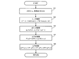
- FIG. 6 is a flowchart of a scalar multiplication operation program that performs processing of the scalar multiplication operation unit.
- the electronic computer 10 performs scalar multiplication based on the activated scalar multiplication calculation program based on the flowchart shown in FIG. 6, stores the calculation result in the storage means, and returns it to the main routine program.
- the case of the third-order GLV method will be described.
- the scalar s data and the rational point P data are input from the pairing operation unit 300 by the activated scalar multiplication operation program, and are input to a predetermined register 490 provided in the CPU 11. Each is input (parameter input unit 410) (step S1).
- the CPU 11 is caused to function as a constant operation means by a scalar multiplication operation program, and the composite number r and the characteristic p of the finite field previously stored in the register 490 are used to obtain the equation (3).
- ⁇ 2 + ⁇ + 1 ⁇ 0 (mod r) and ⁇ 3 ⁇ 1 (mod p) ⁇ ( ⁇ 1) shown in equation (4b) are calculated and set (constant Calculation unit 420) (step S2).
- the scalar multiplication program causes the CPU 11 to function as a self-homogeneous mapping calculation means, and P (x, y) ⁇ ⁇ (P) ( ⁇ x, y) shown in Expression (4b) Arithmetic. That is, a new rational point is obtained by multiplying the x coordinate value of P by ⁇ (self-homogeneous mapping operation unit 430) (step S3).
- the CPU 11 is caused to function as a scalar multiplication operation means by the scalar multiplication operation program, and is expressed by the equation (26).
- [s] P (s 0 + s 1 ⁇ )
- the calculation of s 0 P + s 1 ⁇ (P) is performed based on the following algorithm of [Table 1] as multi-scalar multiplication for simultaneously obtaining the scalar multiplication of two rational points.
- step 1 all the scalar multiplication combinations of the rational points P and Q up to the window width are calculated in advance and stored in the storage means as a table.
- step 2 k i and l i are obtained.
- step 3 a rational point variable R to be obtained is initialized.
- step 4 the following steps 4.1 and 4.2 are repeated from i to d-1 to 0.
- step 4.1 R is multiplied by window width, that is, elliptical multiplication is performed w times.
- step 4.2 the value of k i P + l i Q is elliptically added to R with reference to the table created in step 1.
- step 5 the process returns with R as a return value.
- scalar s is 2000 bits
- s 0 and s 1 are 1000 bits, so that the amount of computation can be halved compared to the binary method, and the scalar multiplication can be speeded up. .
- the electronic computer 10 stores the calculation result in the memory device 13 and returns it to the main routine program.
- the rational point input unit 210 uses the general embedding order of the rational point group on F p which is 1.
- the rational point P′ ⁇ F p [r] is input, and the constant arithmetic unit 220 uses the composite number r and characteristic p stored in advance in the register 290 to obtain ⁇ 2 + ⁇ + shown in Expression (3).
- the scalar value s and the rational point P are input to the parameter input unit 410 as input means, and the composite number stored in the register 490 in advance in the constant operation unit 420.
- ⁇ 2 + ⁇ + 1 ⁇ 0 (mod r) shown in the equation (3) and ⁇ 3 ⁇ 1 (mod p) shown in the equation (4b) are calculated, and the self-homomorphism Self-homogeneous mapping ⁇ (P) is computed in self-homogeneous computing unit 430 which is a mapping computing means, and scalar s is lambda-expanded in ⁇ -adic expansion part 440 which is a ⁇ -adic expansion means, and multi-scalar multiplication is performed.
- the multi-scalar multiplication calculation unit 450 as a means, scalar multiplication [s] P is calculated. By doing so, it is possible to execute scalar multiplication of a rational point whose rational point group has an embedding degree 1 at high speed.
- the scalar multiplication of the present invention is not limited to the above-described embodiment.
- the multi-scalar multiplication calculation unit may perform calculation using JSF (Joint Sparse Form) which is an existing method.
- the rational point group identification program and the scalar multiplication program can be recorded on a computer-readable recording medium. These programs can be stored in a storage device of a server computer and downloaded to a storage device of an electronic computer via a network.
- the pairing operation of the present invention will be described below.
- the calculation of the rational function is performed using the integer ⁇ and the automorphism map ⁇ (P), thereby speeding up the calculation.
- the inventors specify rational point subgroups G 1 and G 2 when the embedding degree of the rational point group is 1 , and calculate the rational function f r, P (Q) based on the characteristics. For example, in the case of the 4th order, it was decided to carry out as follows. First, f ⁇ _4, P (Q) is calculated. Data in the middle of the calculation process is stored in the storage means.
- FIG. 1 is a schematic diagram showing a schematic configuration of a pairing arithmetic device according to an embodiment of the present invention.
- FIG. 2 is a block diagram illustrating the overall configuration of the pairing arithmetic device according to the embodiment of the invention. Since FIG. 1 and FIG. 2 are the same as in the case of scalar multiplication, description thereof will be omitted.
- FIG. 3 is a diagram illustrating a functional configuration of a rational point subgroup specifying unit realized by executing a predetermined program by the apparatus shown in FIG.
- FIG. 4 is a flowchart of a rational point subgroup specifying program that performs processing of the rational point subgroup specifying unit. 3 and 4 are the same as those in the case of scalar multiplication, and therefore description thereof is omitted. ⁇ Pairing calculation program>
- FIG. 7 is a diagram illustrating a functional configuration of a pairing calculation unit realized by executing a predetermined program with the apparatus illustrated in FIG.
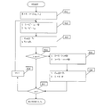
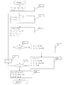
- FIG. 8 is a flowchart of a pairing calculation program for performing processing of the pairing calculation unit.
- the fourth order will be described.
- data of the rational point Q once stored in the memory device 13 as data is respectively input to predetermined registers provided in the CPU (parameter input unit) (step S1).
- the electronic computer 10 causes the CPU 11 to function as the first calculation means by the pairing calculation program, and the rational function by the Miller algorithm.
- f ⁇ _4 P (Q) is calculated and the calculation result is stored in the memory device 13.
- step S2 The rational function f ⁇ — 4, P (Q) is specifically executed as shown in FIG.
- step S2 the intermediate result of T 1 is stored in the memory device 13 by dividing it into elliptic doubling and elliptic addition together with the calculation of the rational function f ⁇ — 4, P (Q).
- T 1 ⁇ P and i is the number of bits when the integer ⁇ is represented in binary (step S31).
- step S32 the CPU 11 is caused to function as the second calculation means to obtain values in the straight line and the perpendicular, and a predetermined calculation associated with the elliptic doubling of the rational function f ⁇ — 4, P (Q) is performed.
- f 1 / h 1 is required to obtain a rational function, but f 1 and h 1 are kept to avoid division each time.
- Step S33 the intermediate result of T 1 is stored in the array C dbl [i] and the elliptical doubling of the rational point variable T 1 is performed and substituted into T 1 .
- the results f 1 and h 1 are stored in the memory device 13, respectively.
- step S4 the variables f 1 and h 1 of the rational function f ⁇ — 4, P (Q) are read from the memory device 13 and initialized. That is, the result in step S3 is set as the initial value in step S5. (Step S4).
- the electronic computer 10 causes the CPU 11 to function as the first calculation means by the pairing calculation program, and the rational function by the Miller algorithm.
- f ⁇ _4, ⁇ 4 (P) (Q) is calculated, and the calculation result is stored in the memory device 13. (Step S5).
- i is the number of bits when the integer ⁇ 4 is represented in binary (step S51).
- step S52 the array C dbl [i] is read from the storage device 13, the CPU 11 is made to function as a self-homogeneous mapping means, ⁇ 4 (C dbl [i]) is obtained, and the result is substituted into T 1. ing.
- step S53 the CPU 11 is made to function as the second calculation means to obtain values in the straight line and the perpendicular, and a predetermined calculation associated with the elliptic doubling of the rational function f ⁇ — 4, P (Q) is performed.
- f 1 / h 1 is required to obtain a rational function, but f 1 and h 1 are kept to avoid division each time.
- step S59 f 1 / h 1 is performed and substituted for f 1 . No division is performed in the loop, and only one division is required.
- f 1 ⁇ (x Q ⁇ x P ) is calculated, the value of f ′ r, P (Q) is obtained, substituted into f 1 , and the result is stored in the memory device 13.
- ⁇ 4i i-th bit from the lowest order when ⁇ 4 is expressed in binary l T1
- T1 (Q) The value of rational point Q on the tangent at rational point T 1 (subscript is correctly T 1 although it is T 1 due to display limitations, and so on) l T1
- P (Q) The value of rational point Q on the straight line passing through rational point T 1 and rational point P v 2T1 (Q): The value of rational point Q in the perpendicular at rational point 2T 1 v T1 + P (Q): The value of rational point Q on the perpendicular at rational point T 1 + P C dbl [i]: Array (memory) for storing i-th doubling 2T 1 C add [i]: Array (memory) for storing the i th addition T 1 + P
- the following algorithm is executed.
- the variable i is initialized to the number of bits when the integer ⁇ 4 is binary-expanded, and the procedure 3 to the procedure 11 are repeated.
- the rational function is divided into straight lines and perpendicular lines. To find the value of a rational function, f 1 / h 1 is required, but division is not performed in the loop to reduce the number of divisions.
- the intermediate result T 1 is assigned to the array C dbl [i].
- step 6 the elliptic point doubling of the rational point T 1 is performed and substituted for T 1 .
- the procedures 8 to 11 are executed.
- the rational function is divided into straight lines and perpendicular lines.
- f 1 / h 1 is required, but division is not performed in the loop to reduce the number of divisions.
- the intermediate result of the rational point variable T 1 is assigned to the array C add [i].
- the rational point variable T 1 and the rational point P are elliptically added and the value is substituted into T 1 .
- the rational point variable T 1 is initialized to the rational point P.
- steps 13 and 14 the results of the first half are assigned to f 2 and h 2 .
- a variable i initially set to the number of bits when expanded integer lambda 4 binary, and repeat Step 16 through Step 22.
- the array C dbl [i] is read from the memory device 13 and self-homogeneous mapping is performed, and the value is assigned to the rational point variable T 1 .
- procedures 17 and 18 the calculation of the rational function is divided into straight lines and perpendicular lines. In order to find the value of a rational function, f 1 / h 1 is required, but in order to reduce the number of divisions, division is not performed in the loop.
- the procedures 20 to 22 are executed.
- the array C add [i] is read from the memory device 13 and self-homogeneous mapping is performed, and the value is substituted into the rational point variable T 1 .
- the rational function is divided into straight lines and perpendicular lines, and f 2 and h 2 are betted to realize ⁇ 4 power.
- the final rational function values f ′ r, P (Q) are obtained and assigned to f 1 .
- the electronic computer 10 causes the CPU 11 to function as the fourth calculation means by the pairing calculation program, reads the value of f ′ r, P (Q) obtained in step S5 from the memory device 13, and performs the pairing e
- the final power multiplication in (P, Q) is performed and the result is stored in the memory device 13 (step S6).
- the electronic computer 10 constituting the authentication server performs authentication processing using the pairing calculation result obtained as described above.
- FIG. 11 and Table 4 are a flowchart and an algorithm in that case. The meaning of the symbols is the same as in Table 2, and the explanation is omitted.
- the rational point T 1 is converted and substituted for T 2 by the self-homogeneous mapping calculation means.
- the calculation of the rational function associated with the ellipse addition is divided into straight lines and perpendicular lines using the second calculation means.
- f 2 / h 2 is required, but to reduce the number of divisions, division is not performed in the loop.
- the elliptic point doubling of the rational point T 1 is performed and substituted for T 1 .
- the rational function operation for T 1 is divided into a straight line and a perpendicular line.
- f 1 / h 1 is required, but in order to reduce the number of divisions, division is not performed in the loop.
- the rational point T 1 is converted and substituted for T 2 by self-homogeneous mapping calculation means.
- the calculation of the rational function associated with the ellipse addition is divided into straight lines and perpendicular lines using the second calculation means.
- f 2 / h 2 is necessary, but in order to reduce the number of divisions, division is not performed in the loop.
- step 15 the rational point variables T 1 and rational point P and the elliptic curve addition and assigns the value to T 1.
- procedures 16 and 17 ⁇ 4 multiplication of f 1 and h 1 is performed.
- steps 18 and 19 the final rational function value f ′ r, P (Q) is obtained and substituted for f 1 .
- the division is performed only once in step 18.
- step 14 the result of the first half is substituted for f 3 , and the ⁇ 3 +1 power is obtained in the procedure 26.
- step 24 the correction term l T1, ⁇ 3 (P) (Q) is multiplied.
- the memory device 13 is used as the storage means for storing each calculation result.
- a register provided in the CPU 11 may be used as the storage means.
- the rational point group identification program and the pairing calculation program can be recorded on a computer-readable recording medium.
- These programs can be stored in a storage device of a server computer and downloaded to a storage device of an electronic computer via a network.
Landscapes
- Engineering & Computer Science (AREA)
- Physics & Mathematics (AREA)
- Theoretical Computer Science (AREA)
- General Physics & Mathematics (AREA)
- Mathematical Analysis (AREA)
- Mathematical Optimization (AREA)
- Pure & Applied Mathematics (AREA)
- Mathematical Physics (AREA)
- Computing Systems (AREA)
- Computational Mathematics (AREA)
- Algebra (AREA)
- Computer Security & Cryptography (AREA)
- Computer Networks & Wireless Communication (AREA)
- Signal Processing (AREA)
- General Engineering & Computer Science (AREA)
- Complex Calculations (AREA)
Abstract
埋め込み次数1かつ合成数位数の楕円曲線上の有理点について、自己準同形写像により定まる部分群を用いることにより、スカラー倍算およびペアリング演算を効率的に行う。
Description
本発明は、有理点Pのスカラー倍算[s]Pを行うスカラー倍算装置、スカラー倍算方法、及びスカラー倍算プログラム、並びにペアリング演算を高速に実行可能としたペアリング演算装置、ペアリング演算方法、及びペアリング演算プログラムに関する。特に、有理点群の埋め込み次数を1とした場合において、有理点Pのスカラー倍算[s]Pを行うスカラー倍算装置、スカラー倍算方法、及びスカラー倍算プログラム、並びに有理点群の埋め込み次数を1とした場合において、ペアリング演算を高速に実行可能としたペアリング演算装置、ペアリング演算方法、及びペアリング演算プログラムに関する。
昨今、インターネットなどの電気通信回線を利用した情報ネットワーク技術が高度に発展し、インターネットによって様々な情報を取得するだけでなく、インターネットバンキングや行政機関への電子申請などのような各種のサービスが提供されてきている。
このようなサービスを利用する場合には、サービスの利用者が成りすましや架空の人間などではなく、適正な利用者であることを確認するための認証処理が必要であり、信頼性の高い認証方法として、公開鍵と秘密鍵を用いる公開鍵暗号をベースとした電子認証技術がよく利用されている。
しかしながら、公開鍵暗号方式の電子認証では、公開鍵あるいは秘密鍵が漏洩した場合には直ちに公開鍵と秘密鍵を変更する必要があり、公開鍵及び秘密鍵の管理を慎重に行わなければならないとともに、必要に応じて新たな公開鍵と秘密鍵の設定登録作業が生じるという煩雑さがあるため、最近では、利用者の氏名やメールアドレスのように利用者特有のIDを用いて電子認証を行うIDベース暗号が用いられることが多くなっている。
また、電子認証を行う認証装置によって利用者の個人認証を行った場合には、認証装置に利用者ごとの履歴が蓄積されることとなり、この履歴情報自体が利用者の個人情報であって、最近では、この履歴情報が漏洩することによる個人情報の漏洩のおそれが指摘されている。
そこで、認証装置では利用者の個人情報を利用して認証を行うのではなく、複数の利用者をひとまとまりのグループとして、このグループに所属していることを示すグループ署名を用いることにより、利用者を特定することなく認証を行うことによって、認証装置に個人情報が蓄積されることなく認証を可能としたグループ署名技術が提案されている。
国家UNS戦略プログラムにおいても、プライバシを保護しつつユーザ認証を行うことのできる匿名認証技術の重要性、必要性が取り上げられている。
UNS:Universal Communications、New Generation Networks、Security and safety
UNS:Universal Communications、New Generation Networks、Security and safety
このようなIDベース暗号やグループ署名等を簡便に実現するための数学的な土台としてペアリング暗号がある。ペアリングとは、楕円曲線上で定義される2入力1出力の関数であり、入力は楕円曲線上の2つの有理点、出力は有限体の元が用いられている。このペアリングは2入力に対して双線形性を持つ。すなわち、例えば、Pを素体Fp上で定義される楕円曲線上の有理点、Qをk次拡大体Fp
k上で定義される楕円曲線上の有理点として、PとQを入力して拡大体F*
p
kの元zが出力されるとき、a倍のPとb倍のQを入力するとzのab乗が出力される。ペアリング暗号ではこの双線形性を利用して暗号システムを構築する。なお、ここで「k」を埋め込み次数と呼び「F*
p
k」は、位数がpkである有限体(拡大体)から単位元0を除いた乗法群を表わす。
楕円曲線上の有理点とは、楕円曲線y2=x3+ax+bを満たす有限体Fqの元の座標(x,y)の組をいう。この集合に無限遠点Oを加えたものは加法群を成し、E(Fq)と表わす。すなわち、楕円曲線上の2つの有理点P、Qを通る直線が楕円曲線と交わる点のx軸を対称とした点をRとすれば、P+Q=Rが成立する。この演算を楕円加算と呼ぶ。PとQが同一点の場合はPを通る接線が楕円曲線と交わる点のx軸を対称とした点をRとすれば、P+P=2P=Rが成立する。この演算を楕円2乗算と呼ぶ。ペアリング暗号及び楕円暗号の安全性の根拠は楕円曲線上の離散対数問題の求解困難性に基づいている。素因数分解の困難性を安全性の根拠とするRSA暗号等と比べ、はるかに短い鍵長で同等の暗号強度(安全性強度)を実現できる。
このような楕円曲線上の有理点のペアリング演算は、ミラーのアルゴリズムを用いて演算するステップとその演算結果に対してべき乗算を行うステップで構成されている。
デジタルグループ署名では、グループに所属する個人ユーザのアクセス権の認証処理を行う際に、アクセス権が失効している個人ユーザを除外するためのペアリング演算を行った後に所定の個人ユーザのペアリング演算を行って認証処理を行うことにより、個人ユーザごとのアクセス権の発行または失効の属性変更に柔軟に対応可能としている。
したがって、例えば、10,000人の個人ユーザで構成されるグループのデジタルグループ署名の場合、アクセス権が失効している個人ユーザが100人いれば、100回のペアリング演算が必要となっており、現時点での一般的な電子計算機による1回のペアリング演算に約0.1秒を要していることから、100回のペアリング演算には約10秒を要することとなってしまうため、実用上、個人ユーザの数が制限されることとなって、広く利用されるものとはなっていなかった。
そこで、ペアリング演算の演算速度を向上させることによりデジタルグループ署名の実用性を向上させるために、例えば、ペアリング演算として楕円曲線上で定義されるTateペアリング演算法を用い、演算負荷を低減させて高速化を図る技術が提案されている(例えば、特許文献1、非特許文献1参照。)。
また、IDベース暗号における暗号化あるいは復号の処理や、グループ署名における認証処理では、できるだけ短時間に実行することが求められる。特にペアリングに基づく暗号方式などにおいてはスカラー倍算が数多く実行されているためスカラー倍算を高速に実行することも求められている。
スカラー倍算の高速化手法として、バイナリー法やWindow法が知られている。
また、自己準同型写像を利用することにより、演算回数を削減して高速化を図る手法も提案されている(例えば、非特許文献2、特許文献2参照。)。
また、自己準同型写像を利用することにより、演算回数を削減して高速化を図る手法も提案されている(例えば、非特許文献2、特許文献2参照。)。
このように、これまでペアリングを用いた暗号方式(IDベース暗号、グループ署名等)は数多く提案され、また、それを高速に実行するために大きな割合を占めるスカラー倍算の高速化手法も数多く提案されているが、その多くは、160ビット以上の素数位数を持つペアリング曲線(ペアリングに効率のよい楕円曲線)を用いるものである。本発明者らはこれまで、土台の数学的構造から、拡大体における計算、楕円曲線暗号の計算、ペアリング計算について出願を行なってきた。そのいずれもが、素数位数のペアリング暗号を効率化するものである。
一方、近年、有理点群の埋め込み次数が1で2000ビットを超える合成数位数(r=22000)を持つペアリング曲線を用いるものが提案されており、また新たなアプリケーションも提案されている(例えば、非特許文献3参照。)。
素数位数のペアリング暗号を効率化するこれまでの手法は、本発明がターゲットとする大きな合成数位数のペアリングに対して即座に適用できるものではない。言い換えれば、合成数位数のペアリング曲線は埋め込み次数が1となるなど特殊な状況におかれるため、これを考慮した新たな高速化手法を提案する必要性がでてきた。埋め込み次数を1とする理由は、ペアリング暗号の暗号強度を必要十分に確保するための強度と効率のバランスを図るのに最も適しているのが埋め込み次数1だからである。埋め込み次数を大きくした場合は暗号強度が十分すぎ、また実現する上での効率が悪くなる。
しかしながら、有理点群の埋め込み次数を1とし合成数位数を用いるアプリケーションに用いるためのペアリング曲線の生成法や、ペアリング計算やスカラー倍算の効率化手法等は未だ十分ではない。
K.Takashima, "Scaling Security of Elliptic Curves with Fast Pairing Using Efficient Endomorphisms",IEICE,vol.90-A,no.1,Jan 2007
R. Gallant, R. Lambert, and S. Vanstone, "Faster Point Multiplication on Elliptic Curves with Efficient Endomorphisms"
D. Boneh, K. Rubin and A. Silverberg, "Finding Composite OrderOrdinary Elliptic Curves Using the Cock-Pinch method"
従来、有理点群の埋め込み次数が1でない場合には、2つの有理点部分群G1,G2を簡便に識別できたため、それらを用いてGLV(Gallant-Lambert-Vanstone)法(スカラー倍算の高速化手法)やXateペアリング(ペアリングの高速化手法)を適用することができた。
しかしながら、有理点群の埋め込み次数を1とした場合、従来のように効率的にスカラー倍算やペアリング計算を行うことができる有理点の部分群を特定する方法がこれまで知られていなかった。そこで、そのような特殊な条件、すなわち、素体上でスカラー倍算を効率的に行えるような有理点だけから成る部分群を識別、特定する必要があった。そして、現在提案されているスカラー倍算及びペアリング演算の高速化は未だに十分ではなく、さらなる高速化が求められている。
本発明者らは、このような現状に鑑み、有理点群の埋め込み次数を1とし大きな合成数位数を持つペアリング曲線におけるスカラー倍算及びペアリング演算を高速化することにより実用性を向上させるべく研究開発を行って、本発明を成すに至ったものである。
本発明のスカラー倍算装置では、
標数pの有限体Fp上で定義された楕円曲線上の有理点の成す加法群をE(Fp)とし、合成数位数rを持つ有理点の集合すなわち前記加法群の部分群をG=E(Fp)[r]として、有理点P∈Gの整数0<s<rによるスカラー倍算[s]Pを演算するCPU及び記憶手段を備えたスカラー倍算装置において、
前記加法群E(Fp)は、埋め込み次数を1とし、
前記CPUは、
有理点P’∈E(Fp)[r]、前記整数s、をそれぞれ入力して前記記憶手段に記憶する入力手段と、
前記記憶手段から前記有理点P’を読み出し、自己準同型写像ψ(P)=λP(λは整数)を満足する前記有理点Pの集合である前記部分群Gを特定し、前記有理点Pを前記記憶手段に記憶する有理点部分群特定手段と、
前記記憶手段から前記有理点Pを読み出し、前記自己準同型写像ψ(P)を演算し、その結果の有理点を前記記憶手段に記憶する自己準同型写像演算手段と、
前記記憶手段から前記整数sを読み出し、次式に基づいてλ進展開し、
s=s0+s1λ
係数s0及びs1を求めその結果を前記記憶手段に記憶するλ進展開手段と、
スカラー倍算を、
[s]P=[s0+s1λ]P=[s0]P+[s1]ψ(P)
として演算し、その結果を前記記憶手段に記憶するマルチ・スカラー倍算演算手段と、を有することとした。
標数pの有限体Fp上で定義された楕円曲線上の有理点の成す加法群をE(Fp)とし、合成数位数rを持つ有理点の集合すなわち前記加法群の部分群をG=E(Fp)[r]として、有理点P∈Gの整数0<s<rによるスカラー倍算[s]Pを演算するCPU及び記憶手段を備えたスカラー倍算装置において、
前記加法群E(Fp)は、埋め込み次数を1とし、
前記CPUは、
有理点P’∈E(Fp)[r]、前記整数s、をそれぞれ入力して前記記憶手段に記憶する入力手段と、
前記記憶手段から前記有理点P’を読み出し、自己準同型写像ψ(P)=λP(λは整数)を満足する前記有理点Pの集合である前記部分群Gを特定し、前記有理点Pを前記記憶手段に記憶する有理点部分群特定手段と、
前記記憶手段から前記有理点Pを読み出し、前記自己準同型写像ψ(P)を演算し、その結果の有理点を前記記憶手段に記憶する自己準同型写像演算手段と、
前記記憶手段から前記整数sを読み出し、次式に基づいてλ進展開し、
s=s0+s1λ
係数s0及びs1を求めその結果を前記記憶手段に記憶するλ進展開手段と、
スカラー倍算を、
[s]P=[s0+s1λ]P=[s0]P+[s1]ψ(P)
として演算し、その結果を前記記憶手段に記憶するマルチ・スカラー倍算演算手段と、を有することとした。
さらに、本発明のスカラー倍算装置では、
前記楕円曲線は、 E:y2 = x3 +b, b∈Fp, 3|(p-1) であり、
前記合成数位数rは、 r|#E(Fp), 3|(r-1) を満たし、
前記整数λは、 λ2+λ +1≡0(mod r) を満たし、
前記自己準同型写像は、ψ:E(Fp)[r] → E(Fp)[r]、
(x,y) → (εx,y), ε3=1, ε(≠1)∈Fp であることにも特徴を有するものである。
前記楕円曲線は、 E:y2 = x3 +b, b∈Fp, 3|(p-1) であり、
前記合成数位数rは、 r|#E(Fp), 3|(r-1) を満たし、
前記整数λは、 λ2+λ +1≡0(mod r) を満たし、
前記自己準同型写像は、ψ:E(Fp)[r] → E(Fp)[r]、
(x,y) → (εx,y), ε3=1, ε(≠1)∈Fp であることにも特徴を有するものである。
さらに、本発明のスカラー倍算装置では、
前記楕円曲線は、 E:y2 = x3 +ax, a∈Fp, 4|(p-1) であり、
前記合成数位数rは、 r|#E(Fp), 4|(r-1) を満たし、
前記整数λは、 λ2+1≡0(mod r) を満たし、
前記自己準同型写像は、ψ:E(Fp)[r] → E(Fp)[r]、
(x,y) → (-x,ζy),ζ4=1, ζ,ζ2(≠1)∈Fpであることにも特徴を有するものである。
前記楕円曲線は、 E:y2 = x3 +ax, a∈Fp, 4|(p-1) であり、
前記合成数位数rは、 r|#E(Fp), 4|(r-1) を満たし、
前記整数λは、 λ2+1≡0(mod r) を満たし、
前記自己準同型写像は、ψ:E(Fp)[r] → E(Fp)[r]、
(x,y) → (-x,ζy),ζ4=1, ζ,ζ2(≠1)∈Fpであることにも特徴を有するものである。
さらに、本発明のスカラー倍算装置では、
前記楕円曲線は、 E:y2 = x3 +b, b∈Fp, 6|(p-1) であり、
前記合成数位数rは、 r|#E(Fp), 3|(r-1) を満たし、
前記整数λは、 λ2-λ +1≡0(mod r) を満たし、
前記自己準同型写像は、ψ:E(Fp)[r] → E(Fp)[r]、
(x,y) → (εx,-y), ε3=1,ε(≠1)∈Fp であることにも特徴を有するものである。
前記楕円曲線は、 E:y2 = x3 +b, b∈Fp, 6|(p-1) であり、
前記合成数位数rは、 r|#E(Fp), 3|(r-1) を満たし、
前記整数λは、 λ2-λ +1≡0(mod r) を満たし、
前記自己準同型写像は、ψ:E(Fp)[r] → E(Fp)[r]、
(x,y) → (εx,-y), ε3=1,ε(≠1)∈Fp であることにも特徴を有するものである。
本発明のスカラー倍算方法では、
標数pの有限体Fp上で定義された楕円曲線上の有理点の成す加法群をE(Fp)とし、合成数位数rを持つ有理点の集合すなわち前記加法群の部分群をG=E(Fp)[r]として、有理点P∈Gの整数0<s<rによるスカラー倍算[s]Pを、CPU及び記憶手段を備えた電子計算機で演算するスカラー倍算方法において、
前記加法群E(Fp)は、埋め込み次数を1とし、
前記電子計算機のCPUを入力手段として機能させて、有理点P’∈E(Fp)[r]、前記整数s、をそれぞれ入力して前記記憶手段に記憶する入力ステップと、
前記電子計算機のCPUを有理点部分群特定手段として機能させて、前記記憶手段からP’を読み出し、自己準同型写像ψ(P)=λP(λは整数)を満足する前記有理点Pの集合である前記部分群Gを特定し、前記有理点Pを前記記憶手段に記憶する有理点部分群特定ステップと、
前記電子計算機のCPUを自己準同型写像演算手段として機能させて、前記記憶手段から前記有理点Pを読み出し、前記自己準同型写像ψ(P)を演算しその結果の有理点を前記記憶手段に記憶する自己準同型写像演算ステップと、
前記電子計算機のCPUをλ進展開手段として機能させて、前記記憶手段から前記整数sを読み出し次式に基づいてλ進展開し、
s=s0+s1λ
係数s0及びs1を求めその結果を前記記憶手段に記憶するλ進展開ステップと、
前記電子計算機のCPUをスカラー倍算演算手段として機能させて、スカラー倍算を、
[s]P=[s0+s1λ]P=[s0]P+[s1]ψ(P)
として演算しその結果を前記記憶手段に記憶するマルチ・スカラー倍算演算ステップと、を有することとした。
標数pの有限体Fp上で定義された楕円曲線上の有理点の成す加法群をE(Fp)とし、合成数位数rを持つ有理点の集合すなわち前記加法群の部分群をG=E(Fp)[r]として、有理点P∈Gの整数0<s<rによるスカラー倍算[s]Pを、CPU及び記憶手段を備えた電子計算機で演算するスカラー倍算方法において、
前記加法群E(Fp)は、埋め込み次数を1とし、
前記電子計算機のCPUを入力手段として機能させて、有理点P’∈E(Fp)[r]、前記整数s、をそれぞれ入力して前記記憶手段に記憶する入力ステップと、
前記電子計算機のCPUを有理点部分群特定手段として機能させて、前記記憶手段からP’を読み出し、自己準同型写像ψ(P)=λP(λは整数)を満足する前記有理点Pの集合である前記部分群Gを特定し、前記有理点Pを前記記憶手段に記憶する有理点部分群特定ステップと、
前記電子計算機のCPUを自己準同型写像演算手段として機能させて、前記記憶手段から前記有理点Pを読み出し、前記自己準同型写像ψ(P)を演算しその結果の有理点を前記記憶手段に記憶する自己準同型写像演算ステップと、
前記電子計算機のCPUをλ進展開手段として機能させて、前記記憶手段から前記整数sを読み出し次式に基づいてλ進展開し、
s=s0+s1λ
係数s0及びs1を求めその結果を前記記憶手段に記憶するλ進展開ステップと、
前記電子計算機のCPUをスカラー倍算演算手段として機能させて、スカラー倍算を、
[s]P=[s0+s1λ]P=[s0]P+[s1]ψ(P)
として演算しその結果を前記記憶手段に記憶するマルチ・スカラー倍算演算ステップと、を有することとした。
さらに、本発明のスカラー倍算方法では、
前記楕円曲線は、 E:y2 = x3 +b, b∈Fp, 3|(p-1) であり、
前記合成数位数rは、 r|#E(Fp), 3|(r-1) を満たし、
前記整数λは、 λ2+λ +1≡0(mod r) を満たし、
前記自己準同型写像は、ψ:E(Fp)[r] → E(Fp)[r]、
(x,y) → (εx,y), ε3=1,ε(≠1)∈Fp であることにも特徴を有するものである。
前記楕円曲線は、 E:y2 = x3 +b, b∈Fp, 3|(p-1) であり、
前記合成数位数rは、 r|#E(Fp), 3|(r-1) を満たし、
前記整数λは、 λ2+λ +1≡0(mod r) を満たし、
前記自己準同型写像は、ψ:E(Fp)[r] → E(Fp)[r]、
(x,y) → (εx,y), ε3=1,ε(≠1)∈Fp であることにも特徴を有するものである。
さらに、本発明のスカラー倍算方法では、
前記楕円曲線は、 E:y2 = x3 +ax, a∈Fp, 4|(p-1) であり、
前記合成数位数rは、 r|#E(Fp), 4|(r-1) を満たし、
前記整数λは、 λ2+1≡0(mod r) を満たし、
前記自己準同型写像は、ψ:E(Fp)[r] → E(Fp)[r]、
(x,y) → (-x,ζy),ζ4=1, ζ,ζ2(≠1)∈Fp であることにも特徴を有するものである。
前記楕円曲線は、 E:y2 = x3 +ax, a∈Fp, 4|(p-1) であり、
前記合成数位数rは、 r|#E(Fp), 4|(r-1) を満たし、
前記整数λは、 λ2+1≡0(mod r) を満たし、
前記自己準同型写像は、ψ:E(Fp)[r] → E(Fp)[r]、
(x,y) → (-x,ζy),ζ4=1, ζ,ζ2(≠1)∈Fp であることにも特徴を有するものである。
さらに、本発明のスカラー倍算方法では、
前記楕円曲線は、 E:y2 = x3 +b, b∈Fp, 6|(p-1) であり、
前記合成数位数rは、 r|#E(Fp), 3|(r-1) を満たし、
前記整数λは、 λ2-λ +1≡0(mod r) を満たし、
前記自己準同型写像は、ψ:E(Fp)[r] → E(Fp)[r]、
(x,y) → (εx,-y), ε3=1,ε(≠1)∈Fp であることにも特徴を有するものである。
前記楕円曲線は、 E:y2 = x3 +b, b∈Fp, 6|(p-1) であり、
前記合成数位数rは、 r|#E(Fp), 3|(r-1) を満たし、
前記整数λは、 λ2-λ +1≡0(mod r) を満たし、
前記自己準同型写像は、ψ:E(Fp)[r] → E(Fp)[r]、
(x,y) → (εx,-y), ε3=1,ε(≠1)∈Fp であることにも特徴を有するものである。
本発明のスカラー倍算プログラムでは、
標数pの有限体Fp上で定義された楕円曲線上の有理点の成す加法群をE(Fp)とし、合成数位数rを持つ有理点の集合すなわち前記加法群の部分群をG=E(Fp)[r]として、有理点P∈Gの整数0<s<rによるスカラー倍算[s]Pを、CPU及び記憶手段を備えた電子計算機に演算させるスカラー倍算プログラムにおいて、
前記加法群E(Fp)は、埋め込み次数を1とし、
前記電子計算機のCPUを、
有理点P’∈E(Fp)[r]、前記整数sをそれぞれ入力し、前記記憶手段に記憶する入力手段、前記記憶手段からP’を読み出し自己準同型写像ψ(P)= λPを満足する前記有理点Pの集合である前記部分群Gを特定し、前記有理点Pを前記記憶手段に記憶する有理点部分群特定手段、
前記記憶手段から前記有理点Pを読み出し、自己準同型写像ψ(P)を演算しその結果の有理点を前記記憶手段に記憶する自己準同型写像演算手段、
前記記憶手段から前記整数sを読み出し、次式に基づいてλ進展開し、
s=s0+s1λ
係数s0及びs1を求めその結果を前記記憶手段に記憶するλ進展開手段、
スカラー倍算を、
[s]P=[s0+s1λ]P=[s0]P+[s1]ψ(P)
として演算し、その結果を前記記憶手段に記憶するマルチ・スカラー倍算演算手段、
として機能させることとした。
標数pの有限体Fp上で定義された楕円曲線上の有理点の成す加法群をE(Fp)とし、合成数位数rを持つ有理点の集合すなわち前記加法群の部分群をG=E(Fp)[r]として、有理点P∈Gの整数0<s<rによるスカラー倍算[s]Pを、CPU及び記憶手段を備えた電子計算機に演算させるスカラー倍算プログラムにおいて、
前記加法群E(Fp)は、埋め込み次数を1とし、
前記電子計算機のCPUを、
有理点P’∈E(Fp)[r]、前記整数sをそれぞれ入力し、前記記憶手段に記憶する入力手段、前記記憶手段からP’を読み出し自己準同型写像ψ(P)= λPを満足する前記有理点Pの集合である前記部分群Gを特定し、前記有理点Pを前記記憶手段に記憶する有理点部分群特定手段、
前記記憶手段から前記有理点Pを読み出し、自己準同型写像ψ(P)を演算しその結果の有理点を前記記憶手段に記憶する自己準同型写像演算手段、
前記記憶手段から前記整数sを読み出し、次式に基づいてλ進展開し、
s=s0+s1λ
係数s0及びs1を求めその結果を前記記憶手段に記憶するλ進展開手段、
スカラー倍算を、
[s]P=[s0+s1λ]P=[s0]P+[s1]ψ(P)
として演算し、その結果を前記記憶手段に記憶するマルチ・スカラー倍算演算手段、
として機能させることとした。
さらに、本発明のスカラー倍算プログラムでは、
前記楕円曲線は、 E:y2 = x3 +b, b∈Fp, 3|(p-1) であり、
前記合成数位数rは、 r|#E(Fp), 3|(r-1) を満たし、
前記整数λは、 λ2+λ +1≡0(mod r) を満たし、
前記自己準同型写像は、ψ:E(Fp)[r] → E(Fp)[r]、
(x,y) → (εx,y), ε3=1,ε(≠1)∈Fp であることにも特徴を有するものである。
前記楕円曲線は、 E:y2 = x3 +b, b∈Fp, 3|(p-1) であり、
前記合成数位数rは、 r|#E(Fp), 3|(r-1) を満たし、
前記整数λは、 λ2+λ +1≡0(mod r) を満たし、
前記自己準同型写像は、ψ:E(Fp)[r] → E(Fp)[r]、
(x,y) → (εx,y), ε3=1,ε(≠1)∈Fp であることにも特徴を有するものである。
さらに、本発明のスカラー倍算プログラムでは、
前記楕円曲線は、 E:y2 = x3 +ax, a∈Fp, 4|(p-1) であり、
前記合成数位数rは、 r|#E(Fp), 4|(r-1) を満たし、
前記整数λは、 λ2+1≡0(mod r) を満たし、
前記自己準同型写像は、ψ:E(Fp)[r] → E(Fp)[r]、
(x,y) → (-x,ζy),ζ4=1, ζ,ζ2(≠1)∈Fp であることにも特徴を有するものである。
前記楕円曲線は、 E:y2 = x3 +ax, a∈Fp, 4|(p-1) であり、
前記合成数位数rは、 r|#E(Fp), 4|(r-1) を満たし、
前記整数λは、 λ2+1≡0(mod r) を満たし、
前記自己準同型写像は、ψ:E(Fp)[r] → E(Fp)[r]、
(x,y) → (-x,ζy),ζ4=1, ζ,ζ2(≠1)∈Fp であることにも特徴を有するものである。
さらに、本発明のスカラー倍算プログラムでは、
前記楕円曲線は、 E:y2 = x3 +b, b∈Fp, 6|(p-1) であり、
前記合成数位数rは、 r|#E(Fp), 3|(r-1) を満たし、
前記整数λは、 λ2-λ +1≡0(mod r) を満たし、
前記自己準同型写像は、ψ:E(Fp)[r] → E(Fp)[r]、
(x,y) → (εx,-y), ε3=1,ε(≠1)∈Fp であることにも特徴を有するものである。
前記楕円曲線は、 E:y2 = x3 +b, b∈Fp, 6|(p-1) であり、
前記合成数位数rは、 r|#E(Fp), 3|(r-1) を満たし、
前記整数λは、 λ2-λ +1≡0(mod r) を満たし、
前記自己準同型写像は、ψ:E(Fp)[r] → E(Fp)[r]、
(x,y) → (εx,-y), ε3=1,ε(≠1)∈Fp であることにも特徴を有するものである。
本発明のペアリング演算装置では、
標数pの有限体Fp上で定義された楕円曲線上の有理点の成す加法群をE(Fp)とし、合成数位数rを持つ有理点の集合すなわち前記加法群の部分群をG1=E(Fp)[r]、G2=E(Fp)[r]として、次式により、
e:G1×G2→F* p/( F* p)r
である非退化な双線形写像としてペアリングeを定義し、
有理点P(xP,yP)∈G1及びQ(xQ,yQ)∈G2、ミラーのアルゴリズムを用いて計算される有理関数をfとして、ペアリングe(P,Q)を演算するCPU及び記憶手段を備えたペアリング演算装置において、
前記加法群E(Fp)は、埋め込み次数を1とし、
前記CPUは、
有理点P’を前記記憶手段に入力する入力手段と、
前記記憶手段から前記有理点P’を読み出し、自己準同型写像ψにより、
λ1P=ψ(P)、λ2Q=ψ(Q) (λ1≠λ2は整数)を満足する前記有理点P及びQの集合である前記部分群G1及びG2を特定する有理点部分群特定手段と、
前記記憶手段から前記有理点PまたはQを読み出し、前記自己準同型写像ψ(P) またはψ(Q)を演算しその結果の有理点を前記記憶手段に記憶する自己準同型写像演算手段と、
前記fを演算する第1演算手段と、
所定の有理点を通る直線及び垂線の前記有理点Qにおける値を演算する第2演算手段と、
前記fと前記値を用いてf’r,p(Q)を演算する第3演算手段と、
前記f’r,p(Q)を用いて前記ペアリングe(P,Q)を

として演算する第4演算手段と
を有することとした。
標数pの有限体Fp上で定義された楕円曲線上の有理点の成す加法群をE(Fp)とし、合成数位数rを持つ有理点の集合すなわち前記加法群の部分群をG1=E(Fp)[r]、G2=E(Fp)[r]として、次式により、
e:G1×G2→F* p/( F* p)r
である非退化な双線形写像としてペアリングeを定義し、
有理点P(xP,yP)∈G1及びQ(xQ,yQ)∈G2、ミラーのアルゴリズムを用いて計算される有理関数をfとして、ペアリングe(P,Q)を演算するCPU及び記憶手段を備えたペアリング演算装置において、
前記加法群E(Fp)は、埋め込み次数を1とし、
前記CPUは、
有理点P’を前記記憶手段に入力する入力手段と、
前記記憶手段から前記有理点P’を読み出し、自己準同型写像ψにより、
λ1P=ψ(P)、λ2Q=ψ(Q) (λ1≠λ2は整数)を満足する前記有理点P及びQの集合である前記部分群G1及びG2を特定する有理点部分群特定手段と、
前記記憶手段から前記有理点PまたはQを読み出し、前記自己準同型写像ψ(P) またはψ(Q)を演算しその結果の有理点を前記記憶手段に記憶する自己準同型写像演算手段と、
前記fを演算する第1演算手段と、
所定の有理点を通る直線及び垂線の前記有理点Qにおける値を演算する第2演算手段と、
前記fと前記値を用いてf’r,p(Q)を演算する第3演算手段と、
前記f’r,p(Q)を用いて前記ペアリングe(P,Q)を
を有することとした。
さらに、本発明のペアリング演算装置では、
前記楕円曲線は、 E:y2 = x3 +ax, a∈Fp, 4|(p-1) であり、
前記合成数位数rは、r|#E(Fp), 4|(r-1) を満たし、
前記整数λ1、λ2は、λ1 2+1≡0(mod r)、λ2 2+1≡0(mod r)を満たし、
前記自己準同型写像は、ψ:E(Fp)[r] → E(Fp)[r]、
(x,y) → (-x,ζy),ζ4=1, ζ,ζ2(≠1)∈Fp であり、
前記f’r,p(Q)は、

であることにも特徴を有するものである。
前記楕円曲線は、 E:y2 = x3 +ax, a∈Fp, 4|(p-1) であり、
前記合成数位数rは、r|#E(Fp), 4|(r-1) を満たし、
前記整数λ1、λ2は、λ1 2+1≡0(mod r)、λ2 2+1≡0(mod r)を満たし、
前記自己準同型写像は、ψ:E(Fp)[r] → E(Fp)[r]、
(x,y) → (-x,ζy),ζ4=1, ζ,ζ2(≠1)∈Fp であり、
前記f’r,p(Q)は、
さらに、本発明のペアリング演算装置では、
前記楕円曲線は、 E:y2 = x3 +b, b∈Fp, 3|(p-1) であり、
前記合成数位数rは、r|#E(Fp), 3|(r-1) を満たし、
前記整数λ1、λ2は、λ1 2+λ1+1≡0(mod r)、λ2 2+λ2 +1≡0(mod r)を満たし、
前記自己準同型写像は、ψ:E(Fp)[r] → E(Fp)[r]、
(x,y) → (εx,y), ε3=1, ε(≠1)∈Fp であり、
前記f’r,p(Q)は、

であることにも特徴を有するものである。
前記楕円曲線は、 E:y2 = x3 +b, b∈Fp, 3|(p-1) であり、
前記合成数位数rは、r|#E(Fp), 3|(r-1) を満たし、
前記整数λ1、λ2は、λ1 2+λ1+1≡0(mod r)、λ2 2+λ2 +1≡0(mod r)を満たし、
前記自己準同型写像は、ψ:E(Fp)[r] → E(Fp)[r]、
(x,y) → (εx,y), ε3=1, ε(≠1)∈Fp であり、
前記f’r,p(Q)は、
さらに、本発明のペアリング演算装置では、
前記楕円曲線は、 E:y2 = x3 +b, b∈Fp, 6|(p-1) であり、
前記合成数位数rは、r|#E(Fp), 3|(r-1) を満たし、
前記整数λ1、λ2は、λ1 2-λ1+1≡0(mod r)、λ2 2-λ2 +1≡0(mod r)を満たし、
前記自己準同型写像は、ψ:E(Fp)[r] → E(Fp)[r]、
(x,y) → (εx,-y), ε3=1, ε(≠1)∈Fp であり、
前記f’r,p(Q)は、

であることにも特徴を有するものである。
前記楕円曲線は、 E:y2 = x3 +b, b∈Fp, 6|(p-1) であり、
前記合成数位数rは、r|#E(Fp), 3|(r-1) を満たし、
前記整数λ1、λ2は、λ1 2-λ1+1≡0(mod r)、λ2 2-λ2 +1≡0(mod r)を満たし、
前記自己準同型写像は、ψ:E(Fp)[r] → E(Fp)[r]、
(x,y) → (εx,-y), ε3=1, ε(≠1)∈Fp であり、
前記f’r,p(Q)は、
本発明のペアリング演算方法では、
標数pの有限体Fp上で定義された楕円曲線上の有理点の成す加法群をE(Fp)とし、合成数位数rを持つ有理点の集合すなわち前記加法群の部分群をG1=E(Fp)[r]、G2=E(Fp)[r]として、次式により、
e:G1×G2→F* p/( F* p)r
である非退化な双線形写像としてペアリングeを定義し、
有理点P(xP,yP)∈G1及びQ(xQ,yQ)∈G2、ミラーのアルゴリズムを用いて計算される有理関数をfとして、CPU及び記憶手段を備えた電子計算機でペアリングe(P,Q)を演算するペアリング演算方法において、
前記加法群E(Fp)は、埋め込み次数を1とし、
前記電子計算機のCPUを入力手段として機能させて、有理点P’を入力し記憶手段に記憶するステップと、
前記電子計算機のCPUを有理点部分群特定手段として機能させて、前記記憶手段から前記有理点P’を読み出し、自己準同型写像ψにより、
λ1P=ψ(P)、λ2Q=ψ(Q) (λ1≠λ2は整数)を満足する前記有理点P及びQの集合である前記部分群G1及びG2を特定するステップと、
前記電子計算機のCPUを自己準同型写像演算手段として機能させて、前記記憶手段から前記有理点PまたはQを読み出し、前記自己準同型写像ψ(P) またはψ(Q)を演算しその結果の有理点を前記記憶手段に記憶する自己準同型写像演算ステップと、
前記電子計算機のCPUを第1演算手段として機能させて、前記fを演算する第1演算ステップと、
前記電子計算機のCPUを第2演算手段として機能させて、所定の有理点を通る直線及び垂線の前記有理点Qにおける値を演算する第2演算ステップと、
前記電子計算機のCPUを第3演算手段として機能させて、前記fと前記値を用いてf’r,p(Q)を演算する第3演算ステップと、
前記電子計算機のCPUを第4演算手段として機能させて、前記f’r,p(Q)を用いて前記ペアリングe(P,Q)を

として演算する第4演算ステップと、
を有することとした。
標数pの有限体Fp上で定義された楕円曲線上の有理点の成す加法群をE(Fp)とし、合成数位数rを持つ有理点の集合すなわち前記加法群の部分群をG1=E(Fp)[r]、G2=E(Fp)[r]として、次式により、
e:G1×G2→F* p/( F* p)r
である非退化な双線形写像としてペアリングeを定義し、
有理点P(xP,yP)∈G1及びQ(xQ,yQ)∈G2、ミラーのアルゴリズムを用いて計算される有理関数をfとして、CPU及び記憶手段を備えた電子計算機でペアリングe(P,Q)を演算するペアリング演算方法において、
前記加法群E(Fp)は、埋め込み次数を1とし、
前記電子計算機のCPUを入力手段として機能させて、有理点P’を入力し記憶手段に記憶するステップと、
前記電子計算機のCPUを有理点部分群特定手段として機能させて、前記記憶手段から前記有理点P’を読み出し、自己準同型写像ψにより、
λ1P=ψ(P)、λ2Q=ψ(Q) (λ1≠λ2は整数)を満足する前記有理点P及びQの集合である前記部分群G1及びG2を特定するステップと、
前記電子計算機のCPUを自己準同型写像演算手段として機能させて、前記記憶手段から前記有理点PまたはQを読み出し、前記自己準同型写像ψ(P) またはψ(Q)を演算しその結果の有理点を前記記憶手段に記憶する自己準同型写像演算ステップと、
前記電子計算機のCPUを第1演算手段として機能させて、前記fを演算する第1演算ステップと、
前記電子計算機のCPUを第2演算手段として機能させて、所定の有理点を通る直線及び垂線の前記有理点Qにおける値を演算する第2演算ステップと、
前記電子計算機のCPUを第3演算手段として機能させて、前記fと前記値を用いてf’r,p(Q)を演算する第3演算ステップと、
前記電子計算機のCPUを第4演算手段として機能させて、前記f’r,p(Q)を用いて前記ペアリングe(P,Q)を
を有することとした。
さらに本発明のペアリング演算方法では、
前記楕円曲線は、 E:y2 = x3 +ax, a∈Fp, 4|(p-1) であり、
前記合成数位数rは、r|#E(Fp), 4|(r-1) を満たし、
前記整数λ1、λ2は、λ1 2+1≡0(mod r)、λ2 2+1≡0(mod r) を満たし、
前記自己準同型写像は、ψ:E(Fp)[r] → E(Fp)[r]、
(x,y) → (-x,ζy),ζ4=1, ζ,ζ2(≠1)∈Fp であり、
前記f’r,p(Q)は、

であることにも特徴を有するものである。
前記楕円曲線は、 E:y2 = x3 +ax, a∈Fp, 4|(p-1) であり、
前記合成数位数rは、r|#E(Fp), 4|(r-1) を満たし、
前記整数λ1、λ2は、λ1 2+1≡0(mod r)、λ2 2+1≡0(mod r) を満たし、
前記自己準同型写像は、ψ:E(Fp)[r] → E(Fp)[r]、
(x,y) → (-x,ζy),ζ4=1, ζ,ζ2(≠1)∈Fp であり、
前記f’r,p(Q)は、
さらに本発明のペアリング演算方法では、
前記楕円曲線は、 E:y2 = x3 +b, b∈Fp, 3|(p-1) であり、
前記合成数位数rは、r|#E(Fp), 3|(r-1) を満たし、
前記整数λ1、λ2は、λ1 2+λ1+1≡0(mod r)、λ2 2+λ2 +1≡0(mod r)を満たし、
前記自己準同型写像は、ψ:E(Fp)[r] → E(Fp)[r]、
(x,y) → (εx,y),ε3=1,ε(≠1)∈Fp であり、
前記f’r,p(Q)は、

であることにも特徴を有するものである。
前記楕円曲線は、 E:y2 = x3 +b, b∈Fp, 3|(p-1) であり、
前記合成数位数rは、r|#E(Fp), 3|(r-1) を満たし、
前記整数λ1、λ2は、λ1 2+λ1+1≡0(mod r)、λ2 2+λ2 +1≡0(mod r)を満たし、
前記自己準同型写像は、ψ:E(Fp)[r] → E(Fp)[r]、
(x,y) → (εx,y),ε3=1,ε(≠1)∈Fp であり、
前記f’r,p(Q)は、
さらに本発明のペアリング演算方法では、
前記楕円曲線は、 E:y2 = x3 +b, b∈Fp, 6|(p-1) であり、
前記合成数位数rは、r|#E(Fp), 3|(r-1) を満たし、
前記整数λ1、λ2は、λ1 2-λ1+1≡0(mod r)、λ2 2-λ2 +1≡0(mod r) であり、
前記自己準同型写像は、ψ:E(Fp)[r] → E(Fp)[r]、
(x,y) → (εx,-y),ε3=1,ε(≠1)∈Fp であり、
前記f’r,p(Q)は、

であることにも特徴を有するものである。
前記楕円曲線は、 E:y2 = x3 +b, b∈Fp, 6|(p-1) であり、
前記合成数位数rは、r|#E(Fp), 3|(r-1) を満たし、
前記整数λ1、λ2は、λ1 2-λ1+1≡0(mod r)、λ2 2-λ2 +1≡0(mod r) であり、
前記自己準同型写像は、ψ:E(Fp)[r] → E(Fp)[r]、
(x,y) → (εx,-y),ε3=1,ε(≠1)∈Fp であり、
前記f’r,p(Q)は、
本発明のペアリング演算プログラムでは、
標数pの有限体Fp上で定義された楕円曲線上の有理点の成す加法群をE(Fp)とし、合成数位数rを持つ有理点の集合すなわち前記加法群の部分群をG1=E(Fp)[r]、G2=E(Fp)[r]として、次式により、
e:G1×G2→F* p/( F* p)r
である非退化な双線形写像としてペアリングeを定義し、
有理点P(xP,yP)∈G1及びQ(xQ,yQ)∈G2、ミラーのアルゴリズムを用いて計算される有理関数をfとして、CPU及び記憶手段を備えた電子計算機にペアリングe(P,Q)を演算させるペアリング演算プログラムにおいて、
前記加法群E(Fp)は、埋め込み次数を1とし、
前記電子計算機のCPUを、有理点P’を入力して記憶手段に記憶する入力手段、
前記記憶手段から前記有理点P’を読み出し、自己準同型写像ψにより、
λ1P=ψ(P)、λ2Q=ψ(Q) (λ1≠λ2は整数)を満足する前記有理点P及びQの集合である前記部分群G1及びG2を特定する有理点部分群特定手段、
前記記憶手段から前記有理点PまたはQを読み出し、前記自己準同型写像ψ(P) またはψ(Q)を演算しその結果の有理点を前記記憶手段に記憶する自己準同型写像演算手段、
前記fを演算する第1演算手段、
所定の有理点を通る直線及び垂線の前記有理点Qにおける値を演算する第2演算手段、
前記fと前記値を用いてf’r,p(Q)を演算する第3演算手段、
前記f’r,p(Q)を用いて前記ペアリングe(P,Q)を

として演算する第4演算手段、
として機能させることとした。
標数pの有限体Fp上で定義された楕円曲線上の有理点の成す加法群をE(Fp)とし、合成数位数rを持つ有理点の集合すなわち前記加法群の部分群をG1=E(Fp)[r]、G2=E(Fp)[r]として、次式により、
e:G1×G2→F* p/( F* p)r
である非退化な双線形写像としてペアリングeを定義し、
有理点P(xP,yP)∈G1及びQ(xQ,yQ)∈G2、ミラーのアルゴリズムを用いて計算される有理関数をfとして、CPU及び記憶手段を備えた電子計算機にペアリングe(P,Q)を演算させるペアリング演算プログラムにおいて、
前記加法群E(Fp)は、埋め込み次数を1とし、
前記電子計算機のCPUを、有理点P’を入力して記憶手段に記憶する入力手段、
前記記憶手段から前記有理点P’を読み出し、自己準同型写像ψにより、
λ1P=ψ(P)、λ2Q=ψ(Q) (λ1≠λ2は整数)を満足する前記有理点P及びQの集合である前記部分群G1及びG2を特定する有理点部分群特定手段、
前記記憶手段から前記有理点PまたはQを読み出し、前記自己準同型写像ψ(P) またはψ(Q)を演算しその結果の有理点を前記記憶手段に記憶する自己準同型写像演算手段、
前記fを演算する第1演算手段、
所定の有理点を通る直線及び垂線の前記有理点Qにおける値を演算する第2演算手段、
前記fと前記値を用いてf’r,p(Q)を演算する第3演算手段、
前記f’r,p(Q)を用いて前記ペアリングe(P,Q)を
として機能させることとした。
さらに本発明のペアリング演算プログラムでは、
前記楕円曲線は、 E:y2 = x3 +ax, a∈Fp, 4|(p-1) であり、
前記合成数位数rは、r|#E(Fp), 4|(r-1) を満たし、
前記整数λ1、λ2は、λ1 2+1≡0(mod r)、λ2 2+1≡0(mod r) であり、
前記自己準同型写像は、ψ:E(Fp)[r] → E(Fp)[r]、
(x,y) → (-x,ζy),ζ4=1, ζ,ζ2(≠1)∈Fp であり、
前記f’r,p(Q)は、

であることにも特徴を有するものである。
前記楕円曲線は、 E:y2 = x3 +ax, a∈Fp, 4|(p-1) であり、
前記合成数位数rは、r|#E(Fp), 4|(r-1) を満たし、
前記整数λ1、λ2は、λ1 2+1≡0(mod r)、λ2 2+1≡0(mod r) であり、
前記自己準同型写像は、ψ:E(Fp)[r] → E(Fp)[r]、
(x,y) → (-x,ζy),ζ4=1, ζ,ζ2(≠1)∈Fp であり、
前記f’r,p(Q)は、
さらに本発明のペアリング演算プログラムでは、
前記楕円曲線は、 E:y2 = x3 +b, b∈Fp, 3|(p-1) であり、
前記合成数位数rは、r|#E(Fp), 3|(r-1) を満たし、
前記整数λ1、λ2は、λ1 2+λ1+1≡0(mod r)、λ2 2+λ2 +1≡0(mod r) であり、
前記自己準同型写像は、ψ:E(Fp)[r] → E(Fp)[r]、
(x,y) → (εx,y),ε3=1,ε(≠1)∈Fp であり、
前記f’r,p(Q)は、

であることにも特徴を有するものである。
前記楕円曲線は、 E:y2 = x3 +b, b∈Fp, 3|(p-1) であり、
前記合成数位数rは、r|#E(Fp), 3|(r-1) を満たし、
前記整数λ1、λ2は、λ1 2+λ1+1≡0(mod r)、λ2 2+λ2 +1≡0(mod r) であり、
前記自己準同型写像は、ψ:E(Fp)[r] → E(Fp)[r]、
(x,y) → (εx,y),ε3=1,ε(≠1)∈Fp であり、
前記f’r,p(Q)は、
さらに本発明のペアリング演算プログラムでは、
前記楕円曲線は、 E:y2 = x3 +b, b∈Fp, 6|(p-1) であり、
前記合成数位数rは、r|#E(Fp), 3|(r-1) を満たし、
前記整数λ1、λ2は、λ1 2-λ1+1≡0(mod r)、λ2 2-λ2 +1≡0(mod r) であり、
前記自己準同型写像は、ψ:E(Fp)[r] → E(Fp)[r]、
(x,y) → (εx,-y),ε3=1,ε(≠1)∈Fp であり、
前記f’r,p(Q)は、

であることにも特徴を有するものである。
前記楕円曲線は、 E:y2 = x3 +b, b∈Fp, 6|(p-1) であり、
前記合成数位数rは、r|#E(Fp), 3|(r-1) を満たし、
前記整数λ1、λ2は、λ1 2-λ1+1≡0(mod r)、λ2 2-λ2 +1≡0(mod r) であり、
前記自己準同型写像は、ψ:E(Fp)[r] → E(Fp)[r]、
(x,y) → (εx,-y),ε3=1,ε(≠1)∈Fp であり、
前記f’r,p(Q)は、
本発明のスカラー倍算によれば、有理点群の埋め込み次数が1の場合において、有理点Pのスカラーsによるスカラー倍算[s]Pを演算するにあたり、
λP=ψ(P) (λは整数)
となる有理点の集合Gを特定して、sをλ進展開してs=s0 +s1λとし、
スカラー倍算[s]Pを、
[s]P=(s0+s1λ)P= s0P +s1ψ(P)
として演算を行うことにより、バイナリー法に比べ、演算量をほぼ半減させることができ、スカラー倍算を高速化することができる。
λP=ψ(P) (λは整数)
となる有理点の集合Gを特定して、sをλ進展開してs=s0 +s1λとし、
スカラー倍算[s]Pを、
[s]P=(s0+s1λ)P= s0P +s1ψ(P)
として演算を行うことにより、バイナリー法に比べ、演算量をほぼ半減させることができ、スカラー倍算を高速化することができる。
また、本発明のペアリング演算によれば、ペアリング演算において、ミラーのアルゴリズムを用いて計算される有理関数の計算を2回行うこととなるが、前半で求めた値を記憶手段に保持しておき、それらを後半の計算に効率よく用いることにより、Tateペアリングと比べ約30%の効率化を図ることができる。
本発明の成果を適用できるようなペアリング曲線は、以下のような条件を満たす必要がある。まず、標数pの有限体Fp上で定義される楕円曲線を、
E/Fp: y2 = x3 +ax +b, a∈Fp b∈Fpとし、
E(Fp):標数pの有限体Fp上で定義される楕円曲線の有理点が成す加法群、
r:E(Fp)の位数#E(Fp)を割り切る合成数、
E[r]:位数が合成数rである有理点の集合、
ψ:有理点に対する自己準同型写像、
t:フロベニウス写像のトレース、
[j]:有理点をj倍する写像、
G:G=E[r]∩Ker(ψ-λ)、(λは整数)を満たす有理点の集合、と定義する。
また、x|yは、xがyを割り切ることを表わすものとする。
E/Fp: y2 = x3 +ax +b, a∈Fp b∈Fpとし、
E(Fp):標数pの有限体Fp上で定義される楕円曲線の有理点が成す加法群、
r:E(Fp)の位数#E(Fp)を割り切る合成数、
E[r]:位数が合成数rである有理点の集合、
ψ:有理点に対する自己準同型写像、
t:フロベニウス写像のトレース、
[j]:有理点をj倍する写像、
G:G=E[r]∩Ker(ψ-λ)、(λは整数)を満たす有理点の集合、と定義する。
また、x|yは、xがyを割り切ることを表わすものとする。
楕円曲線の生成にはCM(Complex Multiplication)法が知られている。標数p、フロベニウス写像のトレースt、判別式Dによる次式のようなCM方程式において、判別式D=1,3の場合を考える。
4p=t2-Ds2 (1)
この時、ペアリング曲線の式はそれぞれ以下のように与えられる。
Ea: y2 = x3 +ax, a∈Fp (D=1) (2a)
Eb: y2 = x3 +b, b∈Fp (D=3) (2b)
本発明者らは、大きな合成数位数に対してこのようなペアリング曲線を生成する簡便な生成法を提案済みである。上記のペアリング曲線上の有理点が簡単な自己準同型写像ψ(即ち有理点をP、整数をλとして、ψ(P)=λP)を持つためには、パラメータの条件がある。これには、以下に示すように、自己準同型写像の周期3,4,6に対応して3次、4次、6次の3つの場合がある。この自己準同型写像をスカラー倍算に用いるのがGLV法である。
また、この自己準同型写像をペアリング演算の高速化にも用いる。
以下に、パラメータの条件及びその写像を示す。
4p=t2-Ds2 (1)
この時、ペアリング曲線の式はそれぞれ以下のように与えられる。
Ea: y2 = x3 +ax, a∈Fp (D=1) (2a)
Eb: y2 = x3 +b, b∈Fp (D=3) (2b)
本発明者らは、大きな合成数位数に対してこのようなペアリング曲線を生成する簡便な生成法を提案済みである。上記のペアリング曲線上の有理点が簡単な自己準同型写像ψ(即ち有理点をP、整数をλとして、ψ(P)=λP)を持つためには、パラメータの条件がある。これには、以下に示すように、自己準同型写像の周期3,4,6に対応して3次、4次、6次の3つの場合がある。この自己準同型写像をスカラー倍算に用いるのがGLV法である。
また、この自己準同型写像をペアリング演算の高速化にも用いる。
以下に、パラメータの条件及びその写像を示す。
<3次の場合>
楕円曲線のパラメータが、3|(p-1), E: y2 =x3 +b, b∈Fp, D=3の場合、
r|#E(Fp), 3|(r-1) を満たす合成数rに対して、次式を満足するある整数λ3が存在する。
λ3 2+λ3 +1≡0(mod r) (3)
また、以下に示す周期3の自己準同型写像ψ3が与えられる。
ψ3:E(Fp)[r] → E(Fp)[r], (4a)

このような合成数rを位数として持つ有理点をP∈E(Fp)[r]とすれば、3次の場合は、[λ3]P=ψ3(P)の関係を用いることでスカラー倍算の効率化を図っている。また、後述のペアリング演算の効率化も図っている。
楕円曲線のパラメータが、3|(p-1), E: y2 =x3 +b, b∈Fp, D=3の場合、
r|#E(Fp), 3|(r-1) を満たす合成数rに対して、次式を満足するある整数λ3が存在する。
λ3 2+λ3 +1≡0(mod r) (3)
また、以下に示す周期3の自己準同型写像ψ3が与えられる。
ψ3:E(Fp)[r] → E(Fp)[r], (4a)
具体的には、スカラー倍算の場合、rに較べて極めて小さいλ3であれば、これは[λ3]Pというスカラー倍算が簡便な自己準同型写像ψ3(P)で求められる(すなわち、有理点Pのx座標値をε倍する演算だけでよい)ことから、スカラーsをλ3進展開することなどによりこの自己準同型写像を効率よく用いてこれを計算する。
しかしながら、有理点群の埋め込み次数が1の場合、一般の有理点P’∈E(Fp)[r]に対しては、[λ3]P’=ψ3(P’)は成り立たない。そのためGLV法は適用することができない。上述したように、これを満たすような有理点の割合は1/r=1/22000 であり、簡便にそのような有理点及び有理点部分群を準備できる必要がある。
本発明では、本発明者らが発見した以下の性質を用いる。
まず、任意の有理点P’∈E(Fp)[r]は次式を満たす。
[(ψ3-λ3)( ψ3 +λ3 +1)]P’=O (5)
ここで、O は無限遠点を表わしている。
すなわち、ランダムに生成した有理点P’∈E(Fp)[r]を(ψ3 +λ3 +1)倍し、
P=[ψ3 +λ3 +1]P’ (6)
とすることにより、その有理点Pは[λ3]P= ψ3(P)を満たすこととなる。そして、そのようなPが生成する有理点部分群をG1 とする。また逆に、
Q=[ψ3 -λ3]P’ (7)
とすれば、[λ3 +1]Q= -ψ3(Q)を満たす有理点Qとなる。そして、そのようなQが生成する有理点部分群をG2 とする。これらG1、G2 を用いて後述のスカラー倍算及びペアリング演算の高速化を実現することができる。
まず、任意の有理点P’∈E(Fp)[r]は次式を満たす。
[(ψ3-λ3)( ψ3 +λ3 +1)]P’=O (5)
ここで、O は無限遠点を表わしている。
すなわち、ランダムに生成した有理点P’∈E(Fp)[r]を(ψ3 +λ3 +1)倍し、
P=[ψ3 +λ3 +1]P’ (6)
とすることにより、その有理点Pは[λ3]P= ψ3(P)を満たすこととなる。そして、そのようなPが生成する有理点部分群をG1 とする。また逆に、
Q=[ψ3 -λ3]P’ (7)
とすれば、[λ3 +1]Q= -ψ3(Q)を満たす有理点Qとなる。そして、そのようなQが生成する有理点部分群をG2 とする。これらG1、G2 を用いて後述のスカラー倍算及びペアリング演算の高速化を実現することができる。
<関係式の導出法の説明>
3次の場合の式(5)の導出について以下に説明する。
まず、任意の有理点P’∈E(Fp)[r]は、E(Fp)のフロベニウス写像のトレースt及びフロベニウス写像φを用いて、次式を満たすことが知られている。
φ:(x,y)→(xp,yp)
(φ2 -tφ+[p])P’= O (8)
同様に、P’をE(Fp)と同型な群を内包する拡大体上ツイスト曲線E’(Fp 3)に写像した有理点P~を考えれば、E’(Fp)のフロベニウス写像のトレースをt’として次式を満たす。
(φ2 -t’φ+[p])P~= O (9)
ここで、ツイスト曲線は、E’:y2 = x3 +bv-2,b∈Fpで与えられ、vはFpの3乗非剰余な元であり、P~は、P’=(x,y)として以下で与えられる。
P~ = (xv2/3,yv) (10)
ここで、上式を写像ψ: P’∈E(Fp)→P~∈E’(Fp 3)とすれば、式(9)は次式のように変形できる。
{(ψ-1φ2ψ)-t’(ψ-1φψ)+[p]}P’=O (11)
そしてこの場合、ψ-1φψ=ψ3が成り立つので次式を得る。
(ψ3 2 -t’ψ3+[p])P’= O (12)
上式に対して、有理点群の埋め込み次数が1であることからp≡1 (mod r)であり、加えてこれに用いる楕円曲線をt’≡-1(3次)、0(4次)、1(6次) (mod r) となるように生成していることから、P’∈E(Fp)[r] (位数rの有理点)とすれば、3次のときには次式を得る。
(ψ3 2 +ψ3+[1])P’= O (13)
一方で3次の場合には、式(3)を満たすような整数λ3も存在し、すなわちψ3 2 +ψ3+1≡0
(mod r)を、ψ3を変数とするような方程式と考えれば、その解の1つがψ3となる。したがって、式(5)のような因数分解された関係式が得られる。
3次の場合の式(5)の導出について以下に説明する。
まず、任意の有理点P’∈E(Fp)[r]は、E(Fp)のフロベニウス写像のトレースt及びフロベニウス写像φを用いて、次式を満たすことが知られている。
φ:(x,y)→(xp,yp)
(φ2 -tφ+[p])P’= O (8)
同様に、P’をE(Fp)と同型な群を内包する拡大体上ツイスト曲線E’(Fp 3)に写像した有理点P~を考えれば、E’(Fp)のフロベニウス写像のトレースをt’として次式を満たす。
(φ2 -t’φ+[p])P~= O (9)
ここで、ツイスト曲線は、E’:y2 = x3 +bv-2,b∈Fpで与えられ、vはFpの3乗非剰余な元であり、P~は、P’=(x,y)として以下で与えられる。
P~ = (xv2/3,yv) (10)
ここで、上式を写像ψ: P’∈E(Fp)→P~∈E’(Fp 3)とすれば、式(9)は次式のように変形できる。
{(ψ-1φ2ψ)-t’(ψ-1φψ)+[p]}P’=O (11)
そしてこの場合、ψ-1φψ=ψ3が成り立つので次式を得る。
(ψ3 2 -t’ψ3+[p])P’= O (12)
上式に対して、有理点群の埋め込み次数が1であることからp≡1 (mod r)であり、加えてこれに用いる楕円曲線をt’≡-1(3次)、0(4次)、1(6次) (mod r) となるように生成していることから、P’∈E(Fp)[r] (位数rの有理点)とすれば、3次のときには次式を得る。
(ψ3 2 +ψ3+[1])P’= O (13)
一方で3次の場合には、式(3)を満たすような整数λ3も存在し、すなわちψ3 2 +ψ3+1≡0
(mod r)を、ψ3を変数とするような方程式と考えれば、その解の1つがψ3となる。したがって、式(5)のような因数分解された関係式が得られる。
<4次の場合>
同様に、楕円曲線のパラメータが、4|(p-1), E: y2=x3 +ax, a∈Fp, D=1の場合、
r|#E(Fp), 4|(r-1) を満たす合成数rに対して、次式を満足するある整数λ4が存在する。 λ4 2+1≡0(mod r) (14)
また、以下に示す周期4の自己準同型写像ψ4が与えられる。
ψ4:E(Fp)[r] → E(Fp)[r], (15a)

このような合成数rを位数として持つ有理点をP∈E(Fp)[r]とすれば、4次の場合は、[λ4]P=ψ4(P)の関係を用いることでスカラー倍算の効率化を図っている。また、後述のペアリング演算の効率化も図っている。
同様に、楕円曲線のパラメータが、4|(p-1), E: y2=x3 +ax, a∈Fp, D=1の場合、
r|#E(Fp), 4|(r-1) を満たす合成数rに対して、次式を満足するある整数λ4が存在する。 λ4 2+1≡0(mod r) (14)
また、以下に示す周期4の自己準同型写像ψ4が与えられる。
ψ4:E(Fp)[r] → E(Fp)[r], (15a)
本発明では、本発明者らが発見した以下の性質を用いる。
まず、任意の有理点P’∈E(Fp)[r]は次式を満たす。
[(ψ4-λ4)( ψ4 +λ4)]P’=O (16)
すなわち、ランダムに生成した有理点P’∈E(Fp)[r]を(ψ4 +λ4 )倍し、
P=[ψ4 +λ4]P’ (17)
とすることにより、その有理点Pは[λ4]P= ψ4(P)を満たすこととなる。そして、そのようなPが生成する有理点部分群をG1 とする。また逆に、
Q=[ψ4 -λ4]P’ (18)
とすれば、[λ4]Q= -ψ4(Q)を満たす有理点Qとなる。そして、そのようなQが生成する有理点部分群をG2 とする。これらG1, G2 を用いて後述のスカラー倍算及びペアリング演算の高速化を実現することができる。
まず、任意の有理点P’∈E(Fp)[r]は次式を満たす。
[(ψ4-λ4)( ψ4 +λ4)]P’=O (16)
すなわち、ランダムに生成した有理点P’∈E(Fp)[r]を(ψ4 +λ4 )倍し、
P=[ψ4 +λ4]P’ (17)
とすることにより、その有理点Pは[λ4]P= ψ4(P)を満たすこととなる。そして、そのようなPが生成する有理点部分群をG1 とする。また逆に、
Q=[ψ4 -λ4]P’ (18)
とすれば、[λ4]Q= -ψ4(Q)を満たす有理点Qとなる。そして、そのようなQが生成する有理点部分群をG2 とする。これらG1, G2 を用いて後述のスカラー倍算及びペアリング演算の高速化を実現することができる。
4次の場合の式(16)の導出については、3次の場合と同様であるので説明は省略する。
<6次の場合>
さらに同様に、楕円曲線のパラメータが、6|(p-1), E: y2 =x3 +b, b∈Fp, D=3の場合、
r|#E(Fp), 3|(r-1) を満たす合成数rに対して、次式を満足するλ6が存在する。
λ6 2-λ6+1≡0(mod r). (19)
また、以下に示す周期6の自己準同型写像ψ6が与えられる。
ψ6:E(Fp)[r] → E(Fp)[r], (20a)

このような位数rを持つ有理点をP∈E(Fp)[r]とし、6次の場合は、[λ6]P=ψ6(P)の関係を用いることでスカラー倍算の効率化を図っている。また、後述のペアリング演算の効率化も図っている。
さらに同様に、楕円曲線のパラメータが、6|(p-1), E: y2 =x3 +b, b∈Fp, D=3の場合、
r|#E(Fp), 3|(r-1) を満たす合成数rに対して、次式を満足するλ6が存在する。
λ6 2-λ6+1≡0(mod r). (19)
また、以下に示す周期6の自己準同型写像ψ6が与えられる。
ψ6:E(Fp)[r] → E(Fp)[r], (20a)
本発明では、本発明者らが発見した以下の性質を用いる。
まず、任意の有理点P’∈E(Fp)[r]は次式を満たす。
[(ψ6-λ6)( ψ6 +λ6-1)]P’=O (22)
すなわち、ランダムに生成した有理点P’∈E(Fp)[r]を(ψ6 +λ6 -1)倍し、
P=[ψ6 +λ6 -1]P’ (23)
とすることにより、その有理点Pは[λ6]P= ψ6(P)を満たすこととなる。そして、そのようなPが生成する有理点部分群をG1 とする。また逆に、
Q=[ψ6 -λ6]P’ (24)
とすれば、[λ6 -1]Q= -ψ6(Q)を満たす有理点Qとなる。そして、そのようなQが生成する有理点部分群をG2 とする。これらG1、G2 を用いて後述のスカラー倍算及びペアリング演算の高速化を実現することができる。
まず、任意の有理点P’∈E(Fp)[r]は次式を満たす。
[(ψ6-λ6)( ψ6 +λ6-1)]P’=O (22)
すなわち、ランダムに生成した有理点P’∈E(Fp)[r]を(ψ6 +λ6 -1)倍し、
P=[ψ6 +λ6 -1]P’ (23)
とすることにより、その有理点Pは[λ6]P= ψ6(P)を満たすこととなる。そして、そのようなPが生成する有理点部分群をG1 とする。また逆に、
Q=[ψ6 -λ6]P’ (24)
とすれば、[λ6 -1]Q= -ψ6(Q)を満たす有理点Qとなる。そして、そのようなQが生成する有理点部分群をG2 とする。これらG1、G2 を用いて後述のスカラー倍算及びペアリング演算の高速化を実現することができる。
6次の場合の式(22)の導出についても、3次の場合と同様であるので説明は省略する。
以下に、本発明のGLV法によるスカラー倍算について説明する。
有理点Pのスカラー0<s<rによるスカラー倍算[s]Pは、sをλ進展開して、
s=s0+s1λ s0,s1<λ (25)
とすると、
[s]P=[ s0+s1λ]P= [s0]P +[s1λ]P=[s0]P +[s1]ψ(P) (26)
となる。
s0、s1はλより小さく、λはrに較べてはるかに小さい。またψ(P)は上述したように簡単な計算(有限体上の乗算1回)で求めることができる。従ってsよりはるかに小さいスカラー値を用いてスカラー倍算を求めることができ、高速化を実現できる。式(26)は複数の有理点のスカラー倍算を求める場合の既存の高速化手法である後述のマルチ・スカラー倍算法([表1]参照。)により求めることができる。λ2≒rであり、s0、s1は、2進数展開したときのビット数が約半分となるので、バイナリー法に比べおおよそ半分の計算時間で求まることとなる。
有理点Pのスカラー0<s<rによるスカラー倍算[s]Pは、sをλ進展開して、
s=s0+s1λ s0,s1<λ (25)
とすると、
[s]P=[ s0+s1λ]P= [s0]P +[s1λ]P=[s0]P +[s1]ψ(P) (26)
となる。
s0、s1はλより小さく、λはrに較べてはるかに小さい。またψ(P)は上述したように簡単な計算(有限体上の乗算1回)で求めることができる。従ってsよりはるかに小さいスカラー値を用いてスカラー倍算を求めることができ、高速化を実現できる。式(26)は複数の有理点のスカラー倍算を求める場合の既存の高速化手法である後述のマルチ・スカラー倍算法([表1]参照。)により求めることができる。λ2≒rであり、s0、s1は、2進数展開したときのビット数が約半分となるので、バイナリー法に比べおおよそ半分の計算時間で求まることとなる。
以下において、本発明のスカラー倍算の実施形態について、図を用いて説明する。図1は、本発明の実施形態にかかるスカラー倍算装置の概略模式図である。図2は、本発明の実施形態にかかるスカラー倍算装置の全体構成を例示したブロック図である。まず、図1及び図2を用いてこの形態の全体について説明し、次にその詳細について説明する。なお、本実施形態では、所要の電子計算機で構成された認証サーバによってデジタルグループ署名の認証処理を行う際に、与えられたペアリング曲線から上述した有理点部分群を特定するプログラム、及び一般的にサブルーチン処理として実行されているスカラー倍算演算プログラム部分についてのみ説明する。なお、有理点部分群の特定及びスカラー倍算の演算は、認証サーバで実行される場合に限定されるものではなく、少なくともCPUなどの演算手段及び記憶手段を備えた装置であれば、どのような装置であってもよい。
図1に示すように、認証サーバを構成する電子計算機10は、演算処理を実行するCPU 11と有理点部分群特定プログラム、スカラー倍算演算プログラム、ペアリング演算プログラムなどの各種プログラム、及びこれらのプログラムで使用するデータなどを記憶したハードディスクなどの記憶装置12と、これらのプログラムを展開して実行可能とするとともに、これらプログラムの実行にともなって生成されたデータを一時的に記憶するRAMなどで構成されたメモリ装置13を備えている。図1中、14はバスである。
また、認証サーバを構成する電子計算機10は、インターネットなどの電気通信回線20に接続して、この電気通信回線20に接続されたクライアント装置30から送信されたデジタルグループ署名の署名データを受信可能としている(図2、認証データ入力部100)。図1中、15は電子計算機10の入出力部である。
認証サーバを構成する電子計算機10では、クライアント装置30からデジタルグループ署名の署名データが送信されると、送信された署名データをメモリ装置13に一旦記憶し(認証データ入力部100)、有理点部分群特定プログラムを起動して効率的な自己準同型写像を可能とする有理点部分群を特定(図2、有理点部分群特定部200)した後、ペアリング演算プログラムを起動して、ペアリング演算を実行している(図2、ペアリング演算部300)。
そして、認証サーバを構成する電子計算機10では、ペアリング演算の実行に際して、所要のスカラー倍算の演算が必要となった場合に、スカラー倍算演算プログラムを起動して、スカラー倍算を実行している(図2、スカラー倍算演算部400)。
その後、認証結果を出力している(図2、認証結果出力部500)。
そして、認証サーバを構成する電子計算機10では、ペアリング演算の実行に際して、所要のスカラー倍算の演算が必要となった場合に、スカラー倍算演算プログラムを起動して、スカラー倍算を実行している(図2、スカラー倍算演算部400)。
その後、認証結果を出力している(図2、認証結果出力部500)。
次に、本実施形態の詳細について図を用いて説明する。
<有理点部分群の特定>
<有理点部分群の特定>
図3は図1で示した装置で所定のプログラムを実行させることにより実現される有理点部分群特定部の機能構成を例示した図である。
図4は有理点部分群特定部の処理を行う有理点部分群特定プログラムのフローチャートである。
電子計算機10では、起動した有理点部分群特定プログラムによって、図4に示すフローチャートに基づいて効率的な自己準同型写像を可能とする有理点部分群を特定している。すなわち、入力された、有理点群が埋め込み次数1の一般の有理点を特定の有理点部分群内の有理点に変換している。この場合電子計算機10は有理点部分群特定手段として機能する。以下では、3次GLV法の場合について説明する。
図4は有理点部分群特定部の処理を行う有理点部分群特定プログラムのフローチャートである。
電子計算機10では、起動した有理点部分群特定プログラムによって、図4に示すフローチャートに基づいて効率的な自己準同型写像を可能とする有理点部分群を特定している。すなわち、入力された、有理点群が埋め込み次数1の一般の有理点を特定の有理点部分群内の有理点に変換している。この場合電子計算機10は有理点部分群特定手段として機能する。以下では、3次GLV法の場合について説明する。
ステップ T1(有理点入力部210)では、外部から与えられ入力手段により記憶手段に記憶された一般の有理点P’を読み出している。
ステップ T2(定数演算部220)では、あらかじめレジスタに記憶された有限体の標数p及び合成数位数rとを用いて、式(3)で示したλ2+λ+1≡0 (mod r)となるλ及び、式(4b)で示したε3≡1 (mod p)となるε(≠1)を演算し設定している。
ステップ T3(自己準同型写像演算部230)では、式(4b)のψ(P’):(x,y)→(εx,y)として、P’のx座標値xをε倍し、ψ(P’)を求めている。
ステップ T4(有理点演算部240)では、式(6)のP=ψ(P’)+(λ+1)P’を計算している。なお、このψ(P’) +(λ+1)P’は2個の有理点スカラー倍算を同時に求める後述の[表1]に基づくアルゴリズムにより求めている。
ステップ T5(判定部250)では、P=O (無限遠点) かどうかを判定している。
P=O の場合は、2つの部分群を特定できないのでエラー・リターンしている。
ステップ T6 (有理点演算部240)では、式(7)のQ=ψ(P’)+(-λ)P’を計算している。なお、このψ(P’)+(-λ)P’も2個の有理点のスカラー倍算を同時に求める後述の[表1]に基づくアルゴリズムにより求めている。
ステップ T7(判定部250)では、Q=O (無限遠点)かどうかを判定している。
Q=O の場合は2つの部分群を特定できないのでエラー・リターンしている)。
ステップ T8では、P、Qを記憶手段に記憶している。Pの集合が有理点部分群G1となり、Qの集合が有理点部分群G2となる。
ステップ T2(定数演算部220)では、あらかじめレジスタに記憶された有限体の標数p及び合成数位数rとを用いて、式(3)で示したλ2+λ+1≡0 (mod r)となるλ及び、式(4b)で示したε3≡1 (mod p)となるε(≠1)を演算し設定している。
ステップ T3(自己準同型写像演算部230)では、式(4b)のψ(P’):(x,y)→(εx,y)として、P’のx座標値xをε倍し、ψ(P’)を求めている。
ステップ T4(有理点演算部240)では、式(6)のP=ψ(P’)+(λ+1)P’を計算している。なお、このψ(P’) +(λ+1)P’は2個の有理点スカラー倍算を同時に求める後述の[表1]に基づくアルゴリズムにより求めている。
ステップ T5(判定部250)では、P=O (無限遠点) かどうかを判定している。
P=O の場合は、2つの部分群を特定できないのでエラー・リターンしている。
ステップ T6 (有理点演算部240)では、式(7)のQ=ψ(P’)+(-λ)P’を計算している。なお、このψ(P’)+(-λ)P’も2個の有理点のスカラー倍算を同時に求める後述の[表1]に基づくアルゴリズムにより求めている。
ステップ T7(判定部250)では、Q=O (無限遠点)かどうかを判定している。
Q=O の場合は2つの部分群を特定できないのでエラー・リターンしている)。
ステップ T8では、P、Qを記憶手段に記憶している。Pの集合が有理点部分群G1となり、Qの集合が有理点部分群G2となる。
本実施形態では、3次GLV法の場合について説明したが、4次GLV法,及び6次GLV法の場合も、λ、ψ(P’)、εまたはζ、P、Qがそれぞれ
4次GLV法では、式(14):λ2+1≡0 (mod r)、
式(15b):ψ(P’):(x,y)→(-x,ζy), (ζ4=1, ζ,ζ2(≠1)∈Fp)、
式(17):P=ψ(P’) +λP’、
式(18):Q=ψ(P’) +(-λ)P’
となり、
6次GLV法では、式(19):λ2-λ+1≡0 (mod r)、
式(20b):ψ(P’):(x,y)→(εx,-y), (ε3=1, ε(≠1)∈Fp)、
式(23):P=ψ(P’) +(λ-1)P’、
式(24):Q=ψ(P’) +(-λ)P’
となるだけであり、同様に有理点部分群を特定することができる(説明は省略する。)。
4次GLV法では、式(14):λ2+1≡0 (mod r)、
式(15b):ψ(P’):(x,y)→(-x,ζy), (ζ4=1, ζ,ζ2(≠1)∈Fp)、
式(17):P=ψ(P’) +λP’、
式(18):Q=ψ(P’) +(-λ)P’
となり、
6次GLV法では、式(19):λ2-λ+1≡0 (mod r)、
式(20b):ψ(P’):(x,y)→(εx,-y), (ε3=1, ε(≠1)∈Fp)、
式(23):P=ψ(P’) +(λ-1)P’、
式(24):Q=ψ(P’) +(-λ)P’
となるだけであり、同様に有理点部分群を特定することができる(説明は省略する。)。
<スカラー倍算演算プログラム>
図5は図1で示した装置で所定のプログラムを実行させることにより実現されるスカラー倍算演算部の機能構成を例示した図である。図6はスカラー倍算演算部の処理を行うスカラー倍算演算プログラムのフローチャートである。
電子計算機10では、起動したスカラー倍算演算プログラムによって、図6に示すフローチャートに基づいてスカラー倍算の演算を行い、演算結果を記憶手段に記憶すると共に、メインルーチンのプログラムに返している。以下では、3次GLV法の場合について説明する。
図5は図1で示した装置で所定のプログラムを実行させることにより実現されるスカラー倍算演算部の機能構成を例示した図である。図6はスカラー倍算演算部の処理を行うスカラー倍算演算プログラムのフローチャートである。
電子計算機10では、起動したスカラー倍算演算プログラムによって、図6に示すフローチャートに基づいてスカラー倍算の演算を行い、演算結果を記憶手段に記憶すると共に、メインルーチンのプログラムに返している。以下では、3次GLV法の場合について説明する。
起動したスカラー倍算演算プログラムによって、電子計算機10では、ペアリング演算部300より、スカラーsのデータ及び、有理点Pのデータ、を入力して、CPU11の内部に設けている所定のレジスタ490にそれぞれ入力している(パラメータ入力部410)(ステップ S1)。
次いで、電子計算機10では、スカラー倍算演算プログラムによってCPU11を定数演算手段として機能させて、あらかじめレジスタ490に格納されている合成数位数r及び有限体の標数pを用いて、式(3)で示したλ2+λ+1≡0 (mod r) となるλ及び式(4b)で示したε3≡1 (mod p) となるε(≠1)を演算しそれぞれ設定している(定数演算部420)(ステップS2)。
次いで、電子計算機10では、スカラー倍算演算プログラムによってCPU11を自己準同型写像演算手段として機能させて、式(4b)で示したP(x,y)→ψ(P)(εx,y)を演算している。すなわち、Pのx座標値をε倍して新たな有理点を求めている(自己準同型写像演算部430)(ステップ S3)。
次いで、電子計算機10では、スカラー倍算演算プログラムによってCPU11をλ進展開手段として機能させて、スカラーsをλ進展開して、式(25)で示した
s=s0+s1λ (mod r)
となる係数s0、s1を演算している(λ進展開部440)(ステップ S4)。
具体的には、s0=s%λ, s1=(s - s0)/λとしている。(%は、剰余演算子、/は除算演算子。)
s=s0+s1λ (mod r)
となる係数s0、s1を演算している(λ進展開部440)(ステップ S4)。
具体的には、s0=s%λ, s1=(s - s0)/λとしている。(%は、剰余演算子、/は除算演算子。)
次いで、電子計算機10では、スカラー倍算演算プログラムによってCPU11をスカラー倍算演算手段として機能させて、式(26)で示した
[s]P=(s0+s1λ)P= s0P+s1λP=s0P+s1ψ(P)としてスカラー倍算[s]Pの演算を行っている(マルチ・スカラー倍算演算部450)(ステップ S5)。
このs0P+s1ψ(P)の演算は、二つの有理点のスカラー倍算の演算を同時に求めるマルチ・スカラー倍算として以下の[表1]のアルゴリズムに基づいて行っている。
[s]P=(s0+s1λ)P= s0P+s1λP=s0P+s1ψ(P)としてスカラー倍算[s]Pの演算を行っている(マルチ・スカラー倍算演算部450)(ステップ S5)。
このs0P+s1ψ(P)の演算は、二つの有理点のスカラー倍算の演算を同時に求めるマルチ・スカラー倍算として以下の[表1]のアルゴリズムに基づいて行っている。
[表1]マルチ・スカラー倍算アルゴリズム
Input: w, k=(kt-1,...,k1,k0)2, l=(lt-1,...,l1,l0)2 , P,Q.
Output: kP +lQ.
(1) Compute iP+jQ for all i,j∈[0,2w-1].
(2) Write k=(kd-1,...,k1,k0) and l=(ld-1,...,l1,l0) , d=[t/w].
(3) R←O.
(4) For i from d-1 down to 0 do
(4.1) R←2wR.
(4.2) R←R+(kiP +liQ).
(5) Return(R).
この場合、このアルゴリズムにおける入力パラメータのkはs0、lはs1、Pは入力した有理点P、Qは有理点ψ(P)となる。wはウインドー巾である。 kj、lj はk、lを2進展開した時の各係数、ki、li はk、lを2w進展開した時の各係数である。全体でd個となる。
ステップ1では、ウインドー巾までの有理点P,Qの全てのスカラー倍算の組合せについて、事前に計算しておきテーブル化して記憶手段に記憶している。
ステップ2では、各ki、liを求めている。
ステップ3では、求めるべき有理点の変数Rを初期化している。
ステップ4では、以下の4.1及び4.2のステップをiがd-1から0まで繰り返している。
ステップ4.1では、Rをウインドー巾倍すなわち楕円2乗算をw回行っている。
ステップ4.2では、ステップ1で作成したテーブルを参照してkiP+liQの値をRに楕円加算している。
ステップ5では、Rを戻り値としてリターンしている。
Input: w, k=(kt-1,...,k1,k0)2, l=(lt-1,...,l1,l0)2 , P,Q.
Output: kP +lQ.
(1) Compute iP+jQ for all i,j∈[0,2w-1].
(2) Write k=(kd-1,...,k1,k0) and l=(ld-1,...,l1,l0) , d=[t/w].
(3) R←O.
(4) For i from d-1 down to 0 do
(4.1) R←2wR.
(4.2) R←R+(kiP +liQ).
(5) Return(R).
この場合、このアルゴリズムにおける入力パラメータのkはs0、lはs1、Pは入力した有理点P、Qは有理点ψ(P)となる。wはウインドー巾である。 kj、lj はk、lを2進展開した時の各係数、ki、li はk、lを2w進展開した時の各係数である。全体でd個となる。
ステップ1では、ウインドー巾までの有理点P,Qの全てのスカラー倍算の組合せについて、事前に計算しておきテーブル化して記憶手段に記憶している。
ステップ2では、各ki、liを求めている。
ステップ3では、求めるべき有理点の変数Rを初期化している。
ステップ4では、以下の4.1及び4.2のステップをiがd-1から0まで繰り返している。
ステップ4.1では、Rをウインドー巾倍すなわち楕円2乗算をw回行っている。
ステップ4.2では、ステップ1で作成したテーブルを参照してkiP+liQの値をRに楕円加算している。
ステップ5では、Rを戻り値としてリターンしている。
このとき、スカラーsが2000ビットであった場合にはs0及びs1は1000 ビットとなるため、バイナリー法に比べ、演算量を半減させることができ、スカラー倍算を高速化することができる。
演算後、電子計算機10では、演算結果をメモリ装置13に記憶するとともにメインルーチンのプログラムに返している。
本実施形態では、3次GLV法の場合について説明したが、4次GLV法,及び6次GLV法の場合も、λ及びψ(P)と、εまたはζがそれぞれ、
4次GLVでは、式(14):λ2+1≡0 (mod r)、
式(15b):ψ(P):(x,y)→(-x,ζy), (ζ4≡1 (mod p))
となり、
6次GLVでは、式(19):λ2-λ+1≡0 (mod r)、
式(20b):ψ(P):(x,y)→(εx,-y), (ε3≡1( mod p))
となるだけであり、同様に演算することができる(説明は省略する。)。
4次GLVでは、式(14):λ2+1≡0 (mod r)、
式(15b):ψ(P):(x,y)→(-x,ζy), (ζ4≡1 (mod p))
となり、
6次GLVでは、式(19):λ2-λ+1≡0 (mod r)、
式(20b):ψ(P):(x,y)→(εx,-y), (ε3≡1( mod p))
となるだけであり、同様に演算することができる(説明は省略する。)。
以上説明したように、本実施形態の有理点部分群特定手段である有理点部分群特定部200では、有理点入力部210において、有理点群の埋め込み次数が1であるFp上の一般の有理点P’∈ Fp[r]を入力し、定数演算部220において、あらかじめレジスタ290に格納された合成数位数r及び標数pを用いて、式(3)に示すλ2 +λ+1≡0 (mod r) 及び式(4b)に示すε3≡1 (mod p)を演算し、自己準同型写像演算部230において自己準同型写像ψ(P’)を演算し、有理点演算部240において有理点P及びQを演算して、有理点部分群を特定している。このようにすることにより、これら有理点部分群の1つを用いてスカラー倍算の演算を高速に行うことができる。
また、本実施形態のスカラー倍算演算部400では、入力手段であるパラメータ入力部410において、スカラー値s及び有理点Pを入力し、定数演算部420において、あらかじめレジスタ490に格納された合成数位数r及び標数pを用いて、式(3)に示すλ2 +λ+1≡0 (mod r) 及び式(4b)に示すε3≡1 (mod p)を演算し、自己準同型写像演算手段である自己準同型演算部430において自己準同型写像ψ(P)を演算し、λ進展開手段であるλ進展開部440においてスカラーsをλ進展開し、マルチ・スカラー倍算演算手段であるマルチ・スカラー倍算演算部450において、スカラー倍算[s]Pを演算している。このようにすることにより有理点群が埋め込み次数1である有理点のスカラー倍算を高速に実行することができる。
なお、本発明のスカラー倍算は、上述の実施形態に限定されるものではない。例えば、マルチ・スカラー倍算演算部では、既存の手法であるJSF(Joint Sparse Form)を用いて演算してもよい。
また、有理点群特定プログラム及びスカラー倍算演算プログラムはコンピュータで読み取り可能な記録媒体に記録することができる。また、これらのプログラムをサーバのコンピュータの記憶装置に記憶しておき、ネットワークを介して電子計算機の記憶装置にダウンロードすることもできる。
以下に本発明のペアリング演算について説明する。
本発明のペアリング演算では、ペアリング演算におけるミラーのアルゴリズムを用いて有理関数を演算する第1のステップと、その結果に対してべき乗算を行う第2のステップのうち、第1のステップにおいて、上記整数λ及び自己準同型写像ψ(P)を用いて有理関数を演算することにより、演算の高速化を図っているものである。
本発明のペアリング演算では、ペアリング演算におけるミラーのアルゴリズムを用いて有理関数を演算する第1のステップと、その結果に対してべき乗算を行う第2のステップのうち、第1のステップにおいて、上記整数λ及び自己準同型写像ψ(P)を用いて有理関数を演算することにより、演算の高速化を図っているものである。
すなわち、従来のペアリング演算では、曲線の式がy2=x3+ax+b,a∈Fp, b∈Fpで与えられ、Fp上の素数位数rを持つ有理点の集合をE[r]とし、埋め込み次数がkでFp
kを定義体とするペアリング可能な楕円曲線上の有理点の成す加法群をE(Fp
k)、φpをフロベニウス自己準同型写像として、
G1=E[r],
G2=E(Fp k)
により、
e:G1×G2→F* p k/( F* p k)r
である非退化な双線形写像としてペアリングeを定義し、有理点P(xP,yP)∈G1及びQ(xQ,yQ)∈G2、ミラーのアルゴリズムを用いて計算される有理関数fr,P(Q)を用いて、ペアリングe(P,Q)を、

として演算していた。これらは、Tateペアリングとして知られているものである。
G1=E[r],
G2=E(Fp k)
により、
e:G1×G2→F* p k/( F* p k)r
である非退化な双線形写像としてペアリングeを定義し、有理点P(xP,yP)∈G1及びQ(xQ,yQ)∈G2、ミラーのアルゴリズムを用いて計算される有理関数fr,P(Q)を用いて、ペアリングe(P,Q)を、
これに対して、本発明者らは、有理点群の埋め込み次数が1の場合において、有理点部分群G1、G2を特定し、その特性により有理関数fr,P(Q)の計算を例えば、4次の場合、以下のように行うこととした。

まず、fλ_4,P(Q)を計算する。この計算の過程で得られる途中のデータを記憶手段に記憶する。続いてfλ_4,ψ4(P)(Q)を計算する際に先の計算とψ4(P)のみが異なること、加えてそれが簡単な写像ψ4を仲介して与えられていることから、先に記憶しておいた計算結果を活用することができ、加えて、その計算の初期値としてfλ_4,P(Q)の計算結果を使うことにより、残りのλ4乗算(べき乗算)も併せて済ませることができる。これにより、おおよそ30%の効率化が図れる。
3次の場合も同様に、

として計算する。
さらに、6次の場合も同様に、
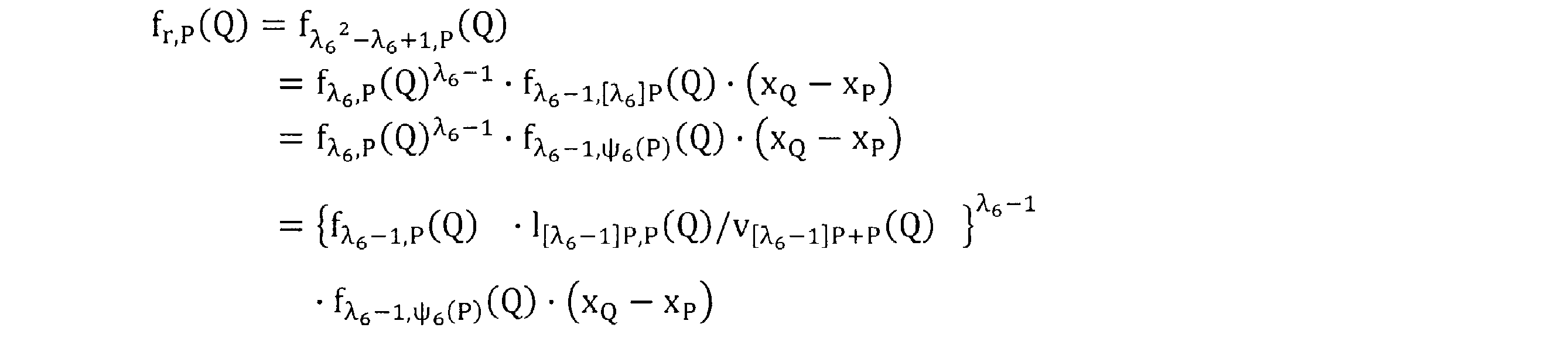
として計算する。
以下において、本発明のペアリング演算の実施形態について、図を用いて説明する。
図1は、本発明の実施形態にかかるペアリング演算装置の概略構成を示す模式図である。
図2は、本発明の実施形態にかかるペアリング演算装置の全体構成を例示したブロック図である。
図1及び図2については、スカラー倍算の場合と同様であるので説明は省略する。
図1は、本発明の実施形態にかかるペアリング演算装置の概略構成を示す模式図である。
図2は、本発明の実施形態にかかるペアリング演算装置の全体構成を例示したブロック図である。
図1及び図2については、スカラー倍算の場合と同様であるので説明は省略する。
次に、本実施形態の詳細について図を用いて説明する。
<有理点部分群の特定>
<有理点部分群の特定>
図3は図1で示した装置で所定のプログラムを実行させることにより実現される有理点部分群特定部の機能構成を例示した図である。
図4は有理点部分群特定部の処理を行う有理点部分群特定プログラムのフローチャートである。
図3及び図4についてもスカラー倍算の場合と同様であるので説明は省略する。
<ペアリング演算プログラム>
図4は有理点部分群特定部の処理を行う有理点部分群特定プログラムのフローチャートである。
図3及び図4についてもスカラー倍算の場合と同様であるので説明は省略する。
<ペアリング演算プログラム>
図7は、図1で示した装置で所定のプログラムを実行させることにより実現されるペアリング演算部の機能構成を例示した図である。
図8は、ペアリング演算部の処理を行うペアリング演算プログラムのフローチャートである。以下では4次の場合について説明する。
図8は、ペアリング演算部の処理を行うペアリング演算プログラムのフローチャートである。以下では4次の場合について説明する。
起動したペアリング演算プロラムによって、電子計算機10では、CPU 11を入力手段として機能させて、メモリ装置13にあらかじめ記憶されている整数λ1=λ4のデータと、有理点Pのデータ、及び署名データとしてメモリ装置13に一旦記憶された有理点QのデータをCPUの内部に設けている所定のレジスタにそれぞれ入力している(パラメータ入力部)(ステップS1)。
次いで、有理関数fλ_4,P(Q)の変数f1,h1を初期化すなわちf1=1、h1=1としている。(ステップS2)
次いで、電子計算機10では、ペアリング演算プログラムによってCPU 11を
第1演算手段として機能させて、ミラーのアルゴリズムによって有理関数
fλ_4,P(Q)を演算しその演算結果をメモリ装置13に記憶している。(ステップS3)。
第1演算手段として機能させて、ミラーのアルゴリズムによって有理関数
fλ_4,P(Q)を演算しその演算結果をメモリ装置13に記憶している。(ステップS3)。
この有理関数fλ_4,P(Q)は、具体的には図9に示すように実行している。
特にステップS2では、有理関数fλ_4,P(Q)の演算とともにT1の中間結果を楕円2倍算、楕円加算に分けてメモリ装置13に記憶している。
特にステップS2では、有理関数fλ_4,P(Q)の演算とともにT1の中間結果を楕円2倍算、楕円加算に分けてメモリ装置13に記憶している。
まず、初期設定としてT1←Pとするとともに整数λを2進数表示とした場合のビット数をiとしている(ステップS31)。
次いで、ステップS32では、CPU 11を第2演算手段として機能させて直線及び垂線における値を求め、有理関数fλ_4,P(Q)の楕円2倍算に伴う所定の演算を行っている。ここで、有理関数を求めるにはf1/h1が必要であるが、都度の除算を避けてf1、h1のままとしている。
次いで、T1の中間結果を配列Cdbl[i]に記憶するとともに有理点変数T1の楕円2倍算を行いT1に代入している。(ステップS33)。
次いで、ステップS34では、整数λ4の低次から数えてi番目のビットの値λ4iが「1」かであるか「0」であるかを判定し、λ4i=1の場合には、ステップS35で、有理関数fλ_4,P(Q)の楕円加算に伴う所定の演算を行っている。ここでも都度の除算を避けてf1、h1のままとしている。ステップS36で、T1の中間結果を配列Cadd[i]に記憶するとともに有理点変数T1の有理点Pとの楕円加算を行いT1に代入している。
次いで、λ4i≠1の場合、iのデクリメントを行って(ステップS38)、ステップS32に戻り、ステップS37でi=1になるまで繰り返すことにより、有理関数fλ_4,P(Q)を演算しその結果であるf1、h1をメモリ装置13にそれぞれ記憶している。
次いで、有理関数fλ_4,P(Q)の変数f1,h1をメモリ装置13から読み出し初期化している。すなわち、ステップS3での結果をステップS5の初期値としている。(ステップS4)。
次いで、電子計算機10では、ペアリング演算プログラムによってCPU 11を
第1演算手段として機能させて、ミラーのアルゴリズムによって有理関数
fλ_4,ψ4(P)(Q)を演算しその演算結果をメモリ装置13に記憶している。(ステップS5)。
第1演算手段として機能させて、ミラーのアルゴリズムによって有理関数
fλ_4,ψ4(P)(Q)を演算しその演算結果をメモリ装置13に記憶している。(ステップS5)。
この有理関数fλ_4,ψ4(P)(Q)は、具体的には図10に示すように実行している。
まず、初期設定として、整数λ4を2進数表示とした場合のビット数をiとしている(ステップS51)
ステップS52では、配列Cdbl[i]を記憶装置13から読み出し、CPU 11を自己準同型写像手段として機能させて、ψ4(Cdbl[i])を求め、その結果をT1に代入している。
次いで、ステップS53では、CPU 11を第2演算手段として機能させて直線及び垂線における値を求め、有理関数fλ_4,P(Q)の楕円2倍算に伴う所定の演算を行っている。ここで、有理関数を求めるにはf1/h1が必要であるが、都度の除算を避けてf1,h1のままとしている。
次いで、ステップS54では、整数λ4の低次から数えてi番目のビットの値λ4iが「1」かであるか「0」であるかを判定し、λ4i=1の場合には、ステップS55でメモリ装置13から配列Cadd[i]を読み出し、CPU 11を自己準同型写像手段として機能させて、ψ4(Cadd[i])を求め、その結果をT1に代入している。ステップS56では、CPU 11を第2演算手段として機能させて直線及び垂線における値を求め、有理関数fλ_4,P(Q)の楕円加算に伴う所定の演算を行っている。ここでも都度の除算を避けてf1、h1のままとしている。
次いで、λ4i≠1の場合、iのデクリメントを行って(ステップS58)、ステップS52に戻り、ステップS57でi=1になるまで繰り返すことにより、有理関数fλ_4,ψ4(P)(Q)を演算している。
次いで、ステップS59では、f1/h1を行いf1に代入している。ループの中で除算を実行することなく、1度の除算で済ませている。次いで、f1・(xQ- xP)を計算しf’r,P(Q)の値を求め、f1に代入し、その結果をメモリ装置13に記憶している。
具体的には、記号の意味を次の通りとして、
λ4i :λ4を2進表記した際の低次からi番目のビット
lT1,T1(Q):有理点T1での接線における有理点Qの値
(表示の制限上、下付き文字は正しくはT1であるがT1としている。以下も同じ。)
lT1,P(Q) :有理点T1と有理点Pを通る直線における有理点Qの値
v2T1(Q) :有理点2T1での垂線における有理点Qの値
vT1+P(Q) :有理点T1+Pでの垂線における有理点Qの値
Cdbl[i] :繰り返し回数がi番目の2倍算2T1を格納するための配列(メモリ)
Cadd[i] :繰り返し回数がi番目の加算T1+Pを格納するための配列(メモリ)
以下のアルゴリズムを実行している。
[表2]ミラーのアルゴリズム1(4次の場合:スピード重視型)
入力:λ4, P∈G1, Q∈G2
出力:f’r,P(Q)
1. f1←1, f2←1, h1←1, h2←1, T1←P
2. For i=[log2(λ4)] down to 1 do:
3. f1←f1 2・lT1,T1(Q).
4. h1←h1 2・v2T1(Q).
5. Cdbl[i] ←T1.
6. T1 ←2T1.
7. if λ4i=1, then:
8. f1←f1・lT1,P(Q).
9. h1←h1・vT1+P(Q).
10. Cadd[i] ←T1.
11. T1←T1+P.
12. T1←P.
13. f2←f1.
14. h2←h1.
15. For i=[log2(λ4)] down to 1 do:
16. T1←ψ4(Cdbl[i]).
17. f1←f1 2・lT1,T1(Q).
18. h1←h1 2・v2T1(Q).
19. if λ4i=1, then:
20. T1←ψ4(Cadd[i]).
21. f1←f1・f2・lT1,P(Q).
22. h1←h1・h2・vT1+P(Q).
23. f1←f1/h1.
24. f1←f1・(xQ-xP).
25. Return f1.
すなわち、CPU 11は、メモリ装置13を用いて上記手順の各演算を行いf‘r,P(Q)を得てその値をメモリ装置13に記憶している。具体的には、手順1では、有理関数変数f1,f2,h1,h2を1に、有理点変数T1を有理点Pに初期設定している。手順2では、変数iを整数λ4を2進数展開した時のビット数に初期設定し、手順3から手順11までを繰り返している。手順3及び4では有理関数の演算を直線及び垂線に分けて行っている。有理関数の値を求めるにはf1/h1が必要であるが除算の回数を減らすためループの中では除算を行わないようにしている。手順5では、中間結果のT1を配列Cdbl[i]に代入している。手順6では、有理点T1の楕円2倍算を行いT1に代入している。手順7では、整数λ4の低次からi番目のビットが「1」か「0」かを判定し「1」の場合に手順8から11を実行している。手順8及び9では有理関数の演算を直線及び垂線に分けて行っている。有理関数の値を求めるにはf1/h1が必要であるが除算の回数を減らすためループの中では除算を行わないようにしている。手順10では、有理点変数T1の中間結果を配列Cadd[i]に代入している。手順11では、有理点変数T1と有理点Pを楕円加算しその値をT1に代入している。
手順12では有理点変数T1を有理点Pに初期設定している。手順13,14では、前半の結果をf2,h2に代入している。手順15では、変数iを、整数λ4を2進数展開した時のビット数に初期設定し、手順16から手順22までを繰り返している。手順16では、配列Cdbl[i]をメモリ装置13から読み出し自己準同型写像を行い、その値を有理点変数T1に代入している。手順17,18では、有理関数の演算を直線及び垂線に分けて行っている。有理関数の値を求めるにはf1/h1が必要であるが除算の回数を減らすためループの中では除算を行わないようにしている。手順19では、整数λ4の低次からi番目のビットが「1」か「0」かを判定し「1」の場合に手順20から22を実行している。手順20では、配列Cadd[i]をメモリ装置13から読み出し自己準同型写像を行い、その値を有理点変数T1に代入している。手順21及び22では、有理関数の演算を直線及び垂線に分けて行うと共にそれぞれf2 、h2を賭け合わせることによりλ4乗を実現している。手順23,24では最終的な有理関数の値f’r,P(Q)を求めf1に代入している。
λ4i :λ4を2進表記した際の低次からi番目のビット
lT1,T1(Q):有理点T1での接線における有理点Qの値
(表示の制限上、下付き文字は正しくはT1であるがT1としている。以下も同じ。)
lT1,P(Q) :有理点T1と有理点Pを通る直線における有理点Qの値
v2T1(Q) :有理点2T1での垂線における有理点Qの値
vT1+P(Q) :有理点T1+Pでの垂線における有理点Qの値
Cdbl[i] :繰り返し回数がi番目の2倍算2T1を格納するための配列(メモリ)
Cadd[i] :繰り返し回数がi番目の加算T1+Pを格納するための配列(メモリ)
以下のアルゴリズムを実行している。
[表2]ミラーのアルゴリズム1(4次の場合:スピード重視型)
入力:λ4, P∈G1, Q∈G2
出力:f’r,P(Q)
1. f1←1, f2←1, h1←1, h2←1, T1←P
2. For i=[log2(λ4)] down to 1 do:
3. f1←f1 2・lT1,T1(Q).
4. h1←h1 2・v2T1(Q).
5. Cdbl[i] ←T1.
6. T1 ←2T1.
7. if λ4i=1, then:
8. f1←f1・lT1,P(Q).
9. h1←h1・vT1+P(Q).
10. Cadd[i] ←T1.
11. T1←T1+P.
12. T1←P.
13. f2←f1.
14. h2←h1.
15. For i=[log2(λ4)] down to 1 do:
16. T1←ψ4(Cdbl[i]).
17. f1←f1 2・lT1,T1(Q).
18. h1←h1 2・v2T1(Q).
19. if λ4i=1, then:
20. T1←ψ4(Cadd[i]).
21. f1←f1・f2・lT1,P(Q).
22. h1←h1・h2・vT1+P(Q).
23. f1←f1/h1.
24. f1←f1・(xQ-xP).
25. Return f1.
すなわち、CPU 11は、メモリ装置13を用いて上記手順の各演算を行いf‘r,P(Q)を得てその値をメモリ装置13に記憶している。具体的には、手順1では、有理関数変数f1,f2,h1,h2を1に、有理点変数T1を有理点Pに初期設定している。手順2では、変数iを整数λ4を2進数展開した時のビット数に初期設定し、手順3から手順11までを繰り返している。手順3及び4では有理関数の演算を直線及び垂線に分けて行っている。有理関数の値を求めるにはf1/h1が必要であるが除算の回数を減らすためループの中では除算を行わないようにしている。手順5では、中間結果のT1を配列Cdbl[i]に代入している。手順6では、有理点T1の楕円2倍算を行いT1に代入している。手順7では、整数λ4の低次からi番目のビットが「1」か「0」かを判定し「1」の場合に手順8から11を実行している。手順8及び9では有理関数の演算を直線及び垂線に分けて行っている。有理関数の値を求めるにはf1/h1が必要であるが除算の回数を減らすためループの中では除算を行わないようにしている。手順10では、有理点変数T1の中間結果を配列Cadd[i]に代入している。手順11では、有理点変数T1と有理点Pを楕円加算しその値をT1に代入している。
手順12では有理点変数T1を有理点Pに初期設定している。手順13,14では、前半の結果をf2,h2に代入している。手順15では、変数iを、整数λ4を2進数展開した時のビット数に初期設定し、手順16から手順22までを繰り返している。手順16では、配列Cdbl[i]をメモリ装置13から読み出し自己準同型写像を行い、その値を有理点変数T1に代入している。手順17,18では、有理関数の演算を直線及び垂線に分けて行っている。有理関数の値を求めるにはf1/h1が必要であるが除算の回数を減らすためループの中では除算を行わないようにしている。手順19では、整数λ4の低次からi番目のビットが「1」か「0」かを判定し「1」の場合に手順20から22を実行している。手順20では、配列Cadd[i]をメモリ装置13から読み出し自己準同型写像を行い、その値を有理点変数T1に代入している。手順21及び22では、有理関数の演算を直線及び垂線に分けて行うと共にそれぞれf2 、h2を賭け合わせることによりλ4乗を実現している。手順23,24では最終的な有理関数の値f’r,P(Q)を求めf1に代入している。
次いで、電子計算機10では、ペアリング演算プログラムによってCPU 11を第4演算手段として機能させて、ステップS5で得られたf’r,P(Q)の値をメモリ装置13から読み出し、ペアリングe(P,Q)における最終べきの、べき乗算を行いその結果をメモリ装置13に記憶している(ステップS6)。
具体的には、
[表3]最終べきのアルゴリズム
1. a←p-1
2. a←a・r-1
3. f’←f’a
4. Return f’
として演算し、f’すなわちe(P,Q)の値をメモリ装置13に記憶している。
[表3]最終べきのアルゴリズム
1. a←p-1
2. a←a・r-1
3. f’←f’a
4. Return f’
として演算し、f’すなわちe(P,Q)の値をメモリ装置13に記憶している。
認証サーバを構成する電子計算機10では、上述したようにして得られたペアリングの演算結果を用いて認証処理を行っている。
以上、4次の場合のペアリング演算について、図8及び表2では、前半のミラー・アルゴリズムの計算の結果を求める際に得られた中間結果をメモリ装置13に記憶しておき後半のミラー・アルゴリズムの計算に活用することによりペアリング演算を高速に実行することとしているが、メモリ容量を節約して実行することもできる。図11及び表4は、その場合のフローチャート及びアルゴリズムである。記号の意味は、表2の場合と同じなので説明は省略する。
[表4]ミラーのアルゴリズム2(4次:メモリ節約型)
入力:λ4, P∈G1, Q∈G2
出力:f’r,P(Q)
1. f1←1, f2←1, h1←1, h2←1, T1←P
2. For i=[log2(λ4)] down to 1 do:
3. f1←f1 2・lT1,T1(Q).
4. h1←h1 2・v2T1(Q).
5. T2←ψ4(T1).
6. f2←f2 2・lT2,T2(Q).
7. h2←h2 2・v2T2(Q).
8. T1←2T1.
9. If λ4i=1, then :
10. f1←f1・lT1,P(Q).
11. h1←h1・vT1+P(Q).
12. T2←ψ4(T1).
13. f2←f2・lT2,P(Q).
14. h2←h2・vT2+P(Q).
15. T1←T1+P.
16. f1←f1 λ_4.
17. h1←h1 λ_4.
18. f1←(f1・f2)/(h1・h2).
19. f1←f1・(xQ-xP).
20. Return f1.
すなわち、手順1では、有理関数変数f1,f2,h1,h2を1に、有理点変数T1を有理点Pに初期設定している。手順2では、変数iを整数λ4を2進数展開した時のビット数に初期設定し、手順3から手順15までを繰り返している。手順3及び4では、第2演算手段を用いて、楕円2倍算にともなう有理関数の演算を直線及び垂線に分けて行っている。有理関数の値を求めるにはf1/h1が必要であるが除算の回数を減らすためループの中では除算を行わないようにしている。手順5では、自己準同型写像演算手段により、有理点T1を変換しT2に代入している。手順6及び7では、第2演算手段を用いて、楕円加算にともなう有理関数の演算を直線及び垂線に分けて行っている。有理関数の値を求めるにはf2/h2が必要であるが除算の回数を減らすためループの中では除算を行わないようにしている。手順8では、有理点T1の楕円2倍算を行いT1に代入している。手順9では、整数λ4の低次からi番目のビットが「1」か「0」かを判定し「1」の場合に手順10から15を実行している。手順10及び11では、T1について有理関数の演算を直線及び垂線に分けて行っている。有理関数の値を求めるにはf1/h1が必要であるが除算の回数を減らすためループの中では除算を行わないようにしている。手順12では、自己準同型写像演算手段により、有理点T1を変換しT2に代入している。手順13及び14では、第2演算手段を用いて、楕円加算にともなう有理関数の演算を直線及び垂線に分けて行っている。有理関数の値を求めるにはf2/h2が必要であるが除算の回数を減らすためループの中では除算を行わないようにしている。手順15では、有理点変数T1と有理点Pを楕円加算しその値をT1に代入している。手順16及び17では、f1及びh1のλ4乗算を行っている。
手順18及び19では最終的な有理関数の値f’r,P(Q)を求めf1に代入している。除算は、手順18の1回だけで済ませている。
[表4]ミラーのアルゴリズム2(4次:メモリ節約型)
入力:λ4, P∈G1, Q∈G2
出力:f’r,P(Q)
1. f1←1, f2←1, h1←1, h2←1, T1←P
2. For i=[log2(λ4)] down to 1 do:
3. f1←f1 2・lT1,T1(Q).
4. h1←h1 2・v2T1(Q).
5. T2←ψ4(T1).
6. f2←f2 2・lT2,T2(Q).
7. h2←h2 2・v2T2(Q).
8. T1←2T1.
9. If λ4i=1, then :
10. f1←f1・lT1,P(Q).
11. h1←h1・vT1+P(Q).
12. T2←ψ4(T1).
13. f2←f2・lT2,P(Q).
14. h2←h2・vT2+P(Q).
15. T1←T1+P.
16. f1←f1 λ_4.
17. h1←h1 λ_4.
18. f1←(f1・f2)/(h1・h2).
19. f1←f1・(xQ-xP).
20. Return f1.
すなわち、手順1では、有理関数変数f1,f2,h1,h2を1に、有理点変数T1を有理点Pに初期設定している。手順2では、変数iを整数λ4を2進数展開した時のビット数に初期設定し、手順3から手順15までを繰り返している。手順3及び4では、第2演算手段を用いて、楕円2倍算にともなう有理関数の演算を直線及び垂線に分けて行っている。有理関数の値を求めるにはf1/h1が必要であるが除算の回数を減らすためループの中では除算を行わないようにしている。手順5では、自己準同型写像演算手段により、有理点T1を変換しT2に代入している。手順6及び7では、第2演算手段を用いて、楕円加算にともなう有理関数の演算を直線及び垂線に分けて行っている。有理関数の値を求めるにはf2/h2が必要であるが除算の回数を減らすためループの中では除算を行わないようにしている。手順8では、有理点T1の楕円2倍算を行いT1に代入している。手順9では、整数λ4の低次からi番目のビットが「1」か「0」かを判定し「1」の場合に手順10から15を実行している。手順10及び11では、T1について有理関数の演算を直線及び垂線に分けて行っている。有理関数の値を求めるにはf1/h1が必要であるが除算の回数を減らすためループの中では除算を行わないようにしている。手順12では、自己準同型写像演算手段により、有理点T1を変換しT2に代入している。手順13及び14では、第2演算手段を用いて、楕円加算にともなう有理関数の演算を直線及び垂線に分けて行っている。有理関数の値を求めるにはf2/h2が必要であるが除算の回数を減らすためループの中では除算を行わないようにしている。手順15では、有理点変数T1と有理点Pを楕円加算しその値をT1に代入している。手順16及び17では、f1及びh1のλ4乗算を行っている。
手順18及び19では最終的な有理関数の値f’r,P(Q)を求めf1に代入している。除算は、手順18の1回だけで済ませている。
以上、本実施形態では、4次の場合について説明したが、3次及び6次の場合でも同様のアルゴリズムでペアリング演算を高速に演算できる。
以下に、3次の場合のアルゴリズムを示す。記号の意味は、表2の場合と同様なので説明は省略する。
[表5]ミラーのアルゴリズム3(3次の場合:スピード重視型)
入力:λ3, P∈G1, Q∈G2
出力:f’r,P(Q)
1. f1←1, f2←1, h1←1, h2←1, T1←P.
2. For i=[log2(λ3)] down to 1 do:
3. f1←f1 2・lT1,T1(Q).
4. h1←h1 2・v2T1(Q).
5. Cdbl[i] ←T1.
6. T1 ←2T1.
7. if λ3i=1, then:
8. f1←f1・lT1,P(Q).
9. h1←h1・vT1+P(Q).
10. Cadd[i] ←T1.
11. T1←T1+P.
12. T1←P.
13. f2←f1.
14. f3←f1 /h1.
15. h2←h1.
16. For i=[log2(λ3)] down to 1 do:
17. T1←ψ3(Cdbl[i]).
18. f1←f1 2・lT1,T1(Q).
19. h1←h1 2・v2T1(Q).
20. if λ3i=1, then:
21. T1←ψ3(Cadd[i]).
22. f1←f1・f2・lT1,P(Q).
23. h1←h1・h2・vT1+P(Q).
24. f1←f1・lT1,ψ3(P)(Q).
25. f1←f1 /h1.
26. f1←f1・f3.
27. Return f1.
3次の場合のアルゴリズムは、4次の場合と同様であるので、異なる部分のみ説明する。
手順14では、前半の結果をf3に代入し、手順26でλ3+1乗を得ている。手順24では、補正項lT1,ψ3(P)(Q)を掛け合わせている。
以下に、3次の場合のアルゴリズムを示す。記号の意味は、表2の場合と同様なので説明は省略する。
[表5]ミラーのアルゴリズム3(3次の場合:スピード重視型)
入力:λ3, P∈G1, Q∈G2
出力:f’r,P(Q)
1. f1←1, f2←1, h1←1, h2←1, T1←P.
2. For i=[log2(λ3)] down to 1 do:
3. f1←f1 2・lT1,T1(Q).
4. h1←h1 2・v2T1(Q).
5. Cdbl[i] ←T1.
6. T1 ←2T1.
7. if λ3i=1, then:
8. f1←f1・lT1,P(Q).
9. h1←h1・vT1+P(Q).
10. Cadd[i] ←T1.
11. T1←T1+P.
12. T1←P.
13. f2←f1.
14. f3←f1 /h1.
15. h2←h1.
16. For i=[log2(λ3)] down to 1 do:
17. T1←ψ3(Cdbl[i]).
18. f1←f1 2・lT1,T1(Q).
19. h1←h1 2・v2T1(Q).
20. if λ3i=1, then:
21. T1←ψ3(Cadd[i]).
22. f1←f1・f2・lT1,P(Q).
23. h1←h1・h2・vT1+P(Q).
24. f1←f1・lT1,ψ3(P)(Q).
25. f1←f1 /h1.
26. f1←f1・f3.
27. Return f1.
3次の場合のアルゴリズムは、4次の場合と同様であるので、異なる部分のみ説明する。
手順14では、前半の結果をf3に代入し、手順26でλ3+1乗を得ている。手順24では、補正項lT1,ψ3(P)(Q)を掛け合わせている。
以下に、6次の場合のアルゴリズムを示す。記号の意味は、表2の場合と同様なので説明は省略する。
[表6]ミラーのアルゴリズム4(6次の場合:スピード重視型)
入力:λ6, P∈G1, Q∈G2
出力:f’r,P(Q)
1. f1←1, f2←1, h1←1, h2←1, T1←P.
2. For i=[log2(λ6-1)] down to 1 do:
3. f1←f1 2・lT1,T1(Q).
4. h1←h1 2・v2T1(Q).
5. Cdbl[i] ←T1.
6. T1 ←2T1.
7. if λ6i=1, then:
8. f1←f1・lT1,P(Q).
9. h1←h1・vT1+P(Q).
10. Cadd[i] ←T1.
11. T1←T1+P.
12. T1←P.
13. f1←f1・lT1,P(Q).
14. h1←h1・vT1+P(Q).
15. f2←f1.
16. h2←h1.
17. For i=[log2(λ6-1)] down to 1 do:
18. T1←ψ6(Cdbl[i]).
19. f1←f1 2・lT1,T1(Q).
20. h1←h1 2・v2T1(Q).
21. if λ6i=1, then:
22. T1←ψ6(Cadd[i]).
23. f1←f1・f2・lT1,P(Q).
24. h1←h1・h2・vT1+P(Q).
25. f1←f1 /h1.
26. f1←f1・(xQ-xP).
27. Return f1.
6次の場合のアルゴリズムも4次の場合と同様であるので異なる部分のみ説明する。
手順2及び17の繰り返し回数はλ6-1回としている。手順13、14では補正項を掛け合わせている。
[表6]ミラーのアルゴリズム4(6次の場合:スピード重視型)
入力:λ6, P∈G1, Q∈G2
出力:f’r,P(Q)
1. f1←1, f2←1, h1←1, h2←1, T1←P.
2. For i=[log2(λ6-1)] down to 1 do:
3. f1←f1 2・lT1,T1(Q).
4. h1←h1 2・v2T1(Q).
5. Cdbl[i] ←T1.
6. T1 ←2T1.
7. if λ6i=1, then:
8. f1←f1・lT1,P(Q).
9. h1←h1・vT1+P(Q).
10. Cadd[i] ←T1.
11. T1←T1+P.
12. T1←P.
13. f1←f1・lT1,P(Q).
14. h1←h1・vT1+P(Q).
15. f2←f1.
16. h2←h1.
17. For i=[log2(λ6-1)] down to 1 do:
18. T1←ψ6(Cdbl[i]).
19. f1←f1 2・lT1,T1(Q).
20. h1←h1 2・v2T1(Q).
21. if λ6i=1, then:
22. T1←ψ6(Cadd[i]).
23. f1←f1・f2・lT1,P(Q).
24. h1←h1・h2・vT1+P(Q).
25. f1←f1 /h1.
26. f1←f1・(xQ-xP).
27. Return f1.
6次の場合のアルゴリズムも4次の場合と同様であるので異なる部分のみ説明する。
手順2及び17の繰り返し回数はλ6-1回としている。手順13、14では補正項を掛け合わせている。
なお、上述においては、各演算結果を記憶する記憶手段としてメモリ装置13を用いることとしたがCPU 11の内部に設けているレジスタを上記記憶手段として用いるようにしてもよい。
また、有理点群特定プログラム及びペアリング演算プログラムはコンピュータで読み取り可能な記録媒体に記録することができる。また、これらのプログラムをサーバのコンピュータの記憶装置に記憶しておき、ネットワークを介して電子計算機の記憶装置にダウンロードすることもできる。
10 電子計算機
11 CPU
12 記憶装置
13 メモリ装置
14 バス
15 入出力制御部
20 電気通信回線
30 クライアント装置
100 認証データ入力部
200 有理点部分群特定部
300 ペアリング演算部
400 スカラー倍算演算部
500 認証結果出力部
210 有理点入力部
220 定数演算部
230 自己準同型演算部
240 有理点演算部
250 判定部
290 レジスタ
310 パラメータ入力部
320 第3演算部
330 第1演算部
340 第2演算部
350 自己準同型写像演算部
360 第4演算部
380 記憶手段
390 レジスタ
410 パラメータ入力部
420 定数演算部
430 自己準同型写像演算部
440 マルチ・スカラー倍算演算部
490 レジスタ
11 CPU
12 記憶装置
13 メモリ装置
14 バス
15 入出力制御部
20 電気通信回線
30 クライアント装置
100 認証データ入力部
200 有理点部分群特定部
300 ペアリング演算部
400 スカラー倍算演算部
500 認証結果出力部
210 有理点入力部
220 定数演算部
230 自己準同型演算部
240 有理点演算部
250 判定部
290 レジスタ
310 パラメータ入力部
320 第3演算部
330 第1演算部
340 第2演算部
350 自己準同型写像演算部
360 第4演算部
380 記憶手段
390 レジスタ
410 パラメータ入力部
420 定数演算部
430 自己準同型写像演算部
440 マルチ・スカラー倍算演算部
490 レジスタ
Claims (24)
- 標数pの有限体Fp上で定義された楕円曲線上の有理点の成す加法群をE(Fp)とし、合成数位数rを持つ有理点の集合すなわち前記加法群の部分群をG=E(Fp)[r]として、有理点P∈Gの整数0<s<rによるスカラー倍算[s]Pを演算するCPU及び記憶手段を備えたスカラー倍算装置において、
前記加法群E(Fp)は、埋め込み次数を1とし、
前記CPUは、
有理点P’∈E(Fp)[r]、前記整数s、をそれぞれ入力して前記記憶手段に記憶する入力手段と、
前記記憶手段から前記有理点P’を読み出し、自己準同型写像ψ(P)=λP(λは整数)を満足する前記有理点Pの集合である前記部分群Gを特定し、前記有理点Pを前記記憶手段に記憶する有理点部分群特定手段と、
前記記憶手段から前記有理点Pを読み出し、前記自己準同型写像ψ(P)を演算し、その結果の有理点を前記記憶手段に記憶する自己準同型写像演算手段と、
前記記憶手段から前記整数sを読み出し、次式に基づいてλ進展開し、
s=s0+s1λ
係数s0及びs1を求めその結果を前記記憶手段に記憶するλ進展開手段と、
スカラー倍算を、
[s]P=[s0 +s1λ]P=[s0]P +[s1]ψ(P)
として演算し、その結果を前記記憶手段に記憶するマルチ・スカラー倍算演算手段と、を有することを特徴とするスカラー倍算装置。 - 前記楕円曲線は、 E:y2 = x3 +b, b∈Fp, 3|(p-1) であり、
前記合成数位数rは、 r|#E(Fp), 3|(r-1) を満たし、
前記整数λは、 λ2+λ +1≡0(mod r) を満たし、
前記自己準同型写像は、ψ:E(Fp)[r] → E(Fp)[r]、
(x,y) → (εx,y), ε3=1,ε(≠1)∈Fp である請求項1に記載のスカラー倍算装置。 - 前記楕円曲線は、 E:y2 = x3 +ax, a∈Fp, 4|(p-1) であり、
前記合成数位数rは、 r|#E(Fp), 4|(r-1) を満たし、
前記整数λは、 λ2+1≡0(mod r) を満たし、
前記自己準同型写像は、ψ:E(Fp)[r] → E(Fp)[r]、
(x,y) → (-x,ζy),ζ4=1,ζ(≠1)∈Fp である請求項1に記載のスカラー倍算装置。 - 前記楕円曲線は、 E:y2 = x3 +b, b∈Fp, 6|(p-1) であり、
前記合成数位数rは、 r|#E(Fp), 3|(r-1) を満たし、
前記整数λは、 λ2-λ +1≡0(mod r) を満たし、
前記自己準同型写像は、ψ:E(Fp)[r] → E(Fp)[r]、
(x,y) → (εx,-y), ε3=1,ε(≠1)∈Fp である請求項1に記載のスカラー倍算装置。 - 標数pの有限体Fp上で定義された楕円曲線上の有理点の成す加法群をE(Fp)とし、合成数位数rを持つ有理点の集合すなわち前記加法群の部分群をG=E(Fp)[r]として、有理点P∈Gの整数0<s<rによるスカラー倍算[s]Pを、CPU及び記憶手段を備えた電子計算機で演算するスカラー倍算方法において、
前記加法群E(Fp)は、埋め込み次数を1とし、
前記電子計算機のCPUを入力手段として機能させて、有理点P’∈E(Fp)[r]、前記整数s、をそれぞれ入力して前記記憶手段に記憶する入力ステップと、
前記電子計算機のCPUを有理点部分群特定手段として機能させて、前記記憶手段からP’を読み出し、自己準同型写像ψ(P)=λP(λは整数)を満足する前記有理点Pの集合である前記部分群Gを特定し、前記有理点Pを前記記憶手段に記憶する有理点部分群特定ステップと、
前記電子計算機のCPUを自己準同型写像演算手段として機能させて、前記記憶手段から前記有理点Pを読み出し、前記自己準同型写像ψ(P)を演算しその結果の有理点を前記記憶手段に記憶する自己準同型写像演算ステップと、
前記電子計算機のCPUをλ進展開手段として機能させて、前記記憶手段から前記整数sを読み出し次式に基づいてλ進展開し、
s=s0+s1λ
係数s0及びs1を求めその結果を前記記憶手段に記憶するλ進展開ステップと、
前記電子計算機のCPUをマルチ・スカラー倍算演算手段として機能させて、スカラー倍算を、
[s]P=[s0 +s1λ]P= [s0]P +[s1]ψ(P)
として演算しその結果を前記記憶手段に記憶するマルチ・スカラー倍算演算ステップと、を有することを特徴とするスカラー倍算方法。 - 前記楕円曲線は、 E:y2 = x3 +b, b∈Fp, 3|(p-1) であり、
前記合成数位数rは、 r|#E(Fp), 3|(r-1) を満たし、
前記整数λは、 λ2+λ +1≡0(mod r) を満たし、
前記自己準同型写像は、ψ:E(Fp)[r] → E(Fp)[r]、
(x,y) → (εx,y), ε3=1,ε(≠1)∈Fp である請求項5に記載のスカラー倍算方法。 - 前記楕円曲線は、 E:y2 = x3 +ax, a∈Fp, 4|(p-1) であり、
前記合成数位数rは、 r|#E(Fp), 4|(r-1) を満たし、
前記整数λは、 λ2+1≡0(mod r) を満たし、
前記自己準同型写像は、ψ:E(Fp)[r] → E(Fp)[r]、
(x,y) → (-x,ζy),ζ4=1,ζ(≠1)∈Fp である請求項5に記載のスカラー倍算方法。 - 前記楕円曲線は、 E:y2 = x3 +b, b∈Fp, 6|(p-1) であり、
前記合成数位数rは、 r|#E(Fp), 3|(r-1) を満たし、
前記整数λは、 λ2-λ +1≡0(mod r) を満たし、
前記自己準同型写像は、ψ:E(Fp)[r] → E(Fp)[r]、
(x,y) → (εx,-y), ε3=1,ε(≠1)∈Fp である請求項5に記載のスカラー倍算方法。 - 標数pの有限体Fp上で定義された楕円曲線上の有理点の成す加法群をE(Fp)とし、合成数位数rを持つ有理点の集合すなわち前記加法群の部分群をG=E(Fp)[r]として、有理点P∈Gの整数0<s<rによるスカラー倍算[s]Pを、CPU及び記憶手段を備えた電子計算機に演算させるスカラー倍算プログラムにおいて、
前記加法群E(Fp)は、埋め込み次数を1とし、
前記電子計算機のCPUを、
有理点P’∈E(Fp)[r]、前記整数sをそれぞれ入力し、前記記憶手段に記憶する入力手段、
前記記憶手段からP’を読み出し自己準同型写像ψ(P)= λPを満足する前記有理点Pの集合である前記部分群Gを特定し、前記有理点Pを前記記憶手段に記憶する有理点部分群特定手段、前記記憶手段から前記有理点Pを読み出し、自己準同型写像ψ(P)を演算しその結果の有理点を前記記憶手段に記憶する自己準同型写像演算手段、
前記記憶手段から前記整数sを読み出し、次式に基づいてλ進展開し、
s=s0+s1λ
係数s0及びs1を求めその結果を前記記憶手段に記憶するλ進展開手段、
スカラー倍算を、
[s]P=[s0 +s1λ]P= [s0]P +[s1]ψ(P)
として演算し、その結果を前記記憶手段に記憶するマルチ・スカラー倍算演算手段、
として機能させることを特徴とするスカラー倍算プログラム。 - 前記楕円曲線は、 E:y2 = x3 +b, b∈Fp, 3|(p-1) であり、
前記合成数位数rは、 r|#E(Fp), 3|(r-1) を満たし、
前記整数λは、 λ2+λ +1≡0(mod r) を満たし、
前記自己準同型写像は、ψ:E(Fp)[r] → E(Fp)[r]、
(x,y) → (εx,y), ε3=1,ε(≠1)∈Fp である請求項9に記載のスカラー倍算プログラム。 - 前記楕円曲線は、 E:y2 = x3 +ax, a∈Fp, 4|(p-1) であり、
前記合成数位数rは、 r|#E(Fp), 4|(r-1) を満たし、
前記整数λは、 λ2+1≡0(mod r) を満たし、
前記自己準同型写像は、ψ:E(Fp)[r] → E(Fp)[r]、
(x,y) → (-x,ζy),ζ4=1,ζ(≠1)∈Fp である請求項9に記載のスカラー倍算プログラム。 - 前記楕円曲線は、 E:y2 = x3 +b, b∈Fp, 6|(p-1) であり、
前記合成数位数rは、 r|#E(Fp), 3|(r-1) を満たし、
前記整数λは、 λ2-λ +1≡0(mod r) を満たし、
前記自己準同型写像は、ψ:E(Fp)[r] → E(Fp)[r]、
(x,y) → (εx,-y), ε3=1,ε(≠1)∈Fp である請求項9に記載のスカラー倍算プログラム。 - 標数pの有限体Fp上で定義された楕円曲線上の有理点の成す加法群をE(Fp)とし、合成数位数rを持つ有理点の集合すなわち前記加法群の部分群をG1=E(Fp)[r]、G2=E(Fp)[r]として、次式により、
e:G1×G2→F* p/( F* p)r
である非退化な双線形写像としてペアリングeを定義し、
有理点P(xP,yP)∈G1及びQ(xQ,yQ)∈G2、ミラーのアルゴリズムを用いて計算される有理関数をfとして、ペアリングe(P,Q)を演算するCPU及び記憶手段を備えたペアリング演算装置において、
前記加法群E(Fp)は、埋め込み次数を1とし、
前記CPUは、
有理点P’を入力して前記記憶手段に記憶する入力手段と、
前記記憶手段から前記有理点P’を読み出し、自己準同型写像ψにより、
λ1P=ψ(P)、λ2Q=ψ(Q) (λ1≠λ2は整数)を満足する前記有理点P及びQの集合である前記部分群G1及びG2を特定する有理点部分群特定手段と、
前記記憶手段から前記有理点PまたはQを読み出し、前記自己準同型写像ψ(P) またはψ(Q)を演算しその結果の有理点を前記記憶手段に記憶する自己準同型写像演算手段と、
前記fを演算する第1演算手段と、
所定の有理点を通る直線及び垂線の前記有理点Qにおける値を演算する第2演算手段と、
前記fと前記値を用いてf’r,p(Q)を演算する第3演算手段と、
前記f’r,p(Q)を用いて前記ペアリングe(P,Q)を

を有するペアリング演算装置。 - 前記楕円曲線は、 E:y2 = x3 +ax, a∈Fp, 4|(p-1) であり、
前記合成数位数rは、r|#E(Fp), 4|(r-1) を満たし、
前記整数λ1、λ2は、λ1 2+1≡0(mod r)、λ2 2+1≡0(mod r)を満たし、
前記自己準同型写像は、ψ:E(Fp)[r] → E(Fp)[r]、
(x,y) → (-x,ζy),ζ4=1, ζ(≠1)∈Fp であり、
前記f’r,p(Q)は、

- 前記楕円曲線は、 E:y2 = x3 +b, b∈Fp, 3|(p-1) であり、
前記合成数位数rは、r|#E(Fp), 3|(r-1) を満たし、
前記整数λ1、λ2は、λ1 2+λ1+1≡0(mod r)、λ2 2+λ2 +1≡0(mod r)を満たし、
前記自己準同型写像は、ψ:E(Fp)[r] → E(Fp)[r]、
(x,y) → (εx,y), ε3=1, ε(≠1)∈Fp であり、
前記f’r,p(Q)は、

- 前記楕円曲線は、 E:y2 = x3 +b, b∈Fp, 6|(p-1) であり、
前記合成数位数rは、r|#E(Fp), 3|(r-1) を満たし、
前記整数λ1、λ2は、λ1 2-λ1+1≡0(mod r)、λ2 2-λ2 +1≡0(mod r)を満たし、
前記自己準同型写像は、ψ:E(Fp)[r] → E(Fp)[r]、
(x,y) → (εx,-y), ε3=1, ε(≠1)∈Fp であり、
前記f’r,p(Q)は、

- 標数pの有限体Fp上で定義された楕円曲線上の有理点の成す加法群をE(Fp)とし、合成数位数rを持つ有理点の集合すなわち前記加法群の部分群をG1=E(Fp)[r]、G2=E(Fp)[r]として、次式により、
e:G1×G2→F* p/( F* p)r
である非退化な双線形写像としてペアリングeを定義し、
有理点P(xP,yP)∈G1及びQ(xQ,yQ)∈G2、ミラーのアルゴリズムを用いて計算される有理関数をfとして、CPU及び記憶手段を備えた電子計算機でペアリングe(P,Q)を演算するペアリング演算方法において、
前記加法群E(Fp)は、埋め込み次数を1とし、
前記電子計算機のCPUを入力手段として機能させて、有理点P’を入力して前記記憶手段に記憶する入力ステップと、
前記電子計算機のCPUを有理点部分群特定手段として機能させて、前記記憶手段から前記有理点P’を読み出し、自己準同型写像ψにより、
λ1P=ψ(P)、λ2Q=ψ(Q) (λ1≠λ2は整数)を満足する前記有理点P及びQの集合である前記部分群G1及びG2を特定するステップと、
前記電子計算機のCPUを自己準同型写像演算手段として機能させて、前記記憶手段から前記有理点PまたはQを読み出し、前記自己準同型写像ψ(P) またはψ(Q)を演算しその結果の有理点を前記記憶手段に記憶する自己準同型写像演算ステップと、
前記電子計算機のCPUを第1演算手段として機能させて、前記fを演算する第1演算ステップと、
前記電子計算機のCPUを第2演算手段として機能させて、所定の有理点を通る直線及び垂線の前記有理点Qにおける値を演算する第2演算ステップと、
前記電子計算機のCPUを第3演算手段として機能させて、前記fと前記値を用いてf’r,p(Q)を演算する第3演算ステップと、
前記電子計算機のCPUを第4演算手段として機能させて、前記f’r,p(Q)を用いて前記ペアリングe(P,Q)を

を有するペアリング演算方法。 - 前記楕円曲線は、 E:y2 = x3 +ax, a∈Fp, 4|(p-1) であり、
前記合成数位数rは、r|#E(Fp), 4|(r-1) を満たし、
前記整数λ1、λ2は、λ1 2+1≡0(mod r)、λ2 2+1≡0(mod r) を満たし、
前記自己準同型写像は、ψ:E(Fp)[r] → E(Fp)[r]、
(x,y) → (-x,ζy),ζ4=1,ζ(≠1)∈Fp であり、
前記f’r,p(Q)は、

- 前記楕円曲線は、 E:y2 = x3 +b, b∈Fp, 3|(p-1) であり、
前記合成数位数rは、r|#E(Fp), 3|(r-1) を満たし、
前記整数λ1、λ2は、λ1 2+λ1+1≡0(mod r)、λ2 2+λ2 +1≡0(mod r)を満たし、
前記自己準同型写像は、ψ:E(Fp)[r] → E(Fp)[r]、
(x,y) → (εx,y),ε3=1,ε(≠1)∈Fp であり、
前記f’r,p(Q)は、

- 前記楕円曲線は、 E:y2 = x3 +b, b∈Fp, 6|(p-1) であり、
前記合成数位数rは、r|#E(Fp), 3|(r-1) を満たし、
前記整数λ1、λ2は、λ1 2-λ1+1≡0(mod r)、λ2 2-λ2 +1≡0(mod r) であり、
前記自己準同型写像は、ψ:E(Fp)[r] → E(Fp)[r]、
(x,y) → (εx,-y),ε3=1,ε(≠1)∈Fp であり、
前記f’r,p(Q)は、

- 標数pの有限体Fp上で定義された楕円曲線上の有理点の成す加法群をE(Fp)とし、合成数位数rを持つ有理点の集合すなわち前記加法群の部分群をG1=E(Fp)[r]、G2=E(Fp)[r]として、次式により、
e:G1×G2→F* p/( F* p)r
である非退化な双線形写像としてペアリングeを定義し、
有理点P(xP,yP)∈G1及びQ(xQ,yQ)∈G2、ミラーのアルゴリズムを用いて計算される有理関数をfとして、CPU及び記憶手段を備えた電子計算機にペアリングe(P,Q)を演算させるペアリング演算プログラムにおいて、
前記加法群E(Fp)は、埋め込み次数を1とし、
前記電子計算機のCPUを、有理点P’を入力して前記記憶手段に記憶する入力手段、
前記記憶手段から前記有理点P’を読み出し、自己準同型写像ψにより、
λ1P=ψ(P)、λ2Q=ψ(Q) (λ1≠λ2は整数)を満足する前記有理点P及びQの集合である前記部分群G1及びG2を特定する有理点部分群特定手段、
前記記憶手段から前記有理点PまたはQを読み出し、前記自己準同型写像ψ(P) またはψ(Q)を演算しその結果の有理点を前記記憶手段に記憶する自己準同型写像演算手段、
前記fを演算する第1演算手段、
所定の有理点を通る直線及び垂線の前記有理点Qにおける値を演算する第2演算手段、
前記fと前記値を用いてf’r,p(Q)を演算する第3演算手段、
前記f’r,p(Q)を用いて前記ペアリングe(P,Q)を

として機能させるペアリング演算プログラム。 - 前記楕円曲線は、 E:y2 = x3 +ax, a∈Fp, 4|(p-1) であり、
前記合成数位数rは、r|#E(Fp), 4|(r-1) を満たし、
前記整数λ1、λ2は、λ1 2+1≡0(mod r)、λ2 2+1≡0(mod r) であり、
前記自己準同型写像は、ψ:E(Fp)[r] → E(Fp)[r]、
(x,y) → (-x,ζy),ζ4=1,ζ(≠1)∈Fp であり、
前記f’r,p(Q)は、

- 前記楕円曲線は、 E:y2 = x3 +b, b∈Fp, 3|(p-1) であり、
前記合成数位数rは、r|#E(Fp), 3|(r-1) を満たし、
前記整数λ1、λ2は、λ1 2+λ1+1≡0(mod r)、λ2 2+λ2 +1≡0(mod r) であり、
前記自己準同型写像は、ψ:E(Fp)[r] → E(Fp)[r]、
(x,y) → (εx,y),ε3=1,ε(≠1)∈Fp であり、
前記f’r,p(Q)は、

- 前記楕円曲線は、 E:y2 = x3 +b, b∈Fp, 6|(p-1) であり、
前記合成数位数rは、r|#E(Fp), 3|(r-1) を満たし、
前記整数λ1、λ2は、λ1 2-λ1+1≡0(mod r)、λ2 2-λ2 +1≡0(mod r) であり、
前記自己準同型写像は、ψ:E(Fp)[r] → E(Fp)[r]、
(x,y) → (εx,-y),ε3=1,ε(≠1)∈Fp であり、
前記f’r,p(Q)は、

Priority Applications (1)
| Application Number | Priority Date | Filing Date | Title |
|---|---|---|---|
| JP2012526601A JPWO2012015047A1 (ja) | 2010-07-30 | 2011-07-29 | 埋め込み次数1かつ合成数位数の楕円曲線上の有理点のスカラー倍算およびペアリング演算 |
Applications Claiming Priority (4)
| Application Number | Priority Date | Filing Date | Title |
|---|---|---|---|
| JP2010-173064 | 2010-07-30 | ||
| JP2010-173065 | 2010-07-30 | ||
| JP2010173065 | 2010-07-30 | ||
| JP2010173064 | 2010-07-30 |
Publications (1)
| Publication Number | Publication Date |
|---|---|
| WO2012015047A1 true WO2012015047A1 (ja) | 2012-02-02 |
Family
ID=45530246
Family Applications (1)
| Application Number | Title | Priority Date | Filing Date |
|---|---|---|---|
| PCT/JP2011/067520 Ceased WO2012015047A1 (ja) | 2010-07-30 | 2011-07-29 | 埋め込み次数1かつ合成数位数の楕円曲線上の有理点のスカラー倍算およびペアリング演算 |
Country Status (2)
| Country | Link |
|---|---|
| JP (1) | JPWO2012015047A1 (ja) |
| WO (1) | WO2012015047A1 (ja) |
Cited By (2)
| Publication number | Priority date | Publication date | Assignee | Title |
|---|---|---|---|---|
| KR101618941B1 (ko) * | 2014-01-09 | 2016-05-09 | 서울대학교산학협력단 | 동형 암호 알고리즘과 페어링 기반 암호 알고리즘을 이용하여, 암호화 데이터를 연산하는 방법 및 이를 이용한 서버 |
| CN113711266A (zh) * | 2019-04-17 | 2021-11-26 | 株式会社日本显示器 | 检测装置 |
-
2011
- 2011-07-29 JP JP2012526601A patent/JPWO2012015047A1/ja active Pending
- 2011-07-29 WO PCT/JP2011/067520 patent/WO2012015047A1/ja not_active Ceased
Non-Patent Citations (2)
| Title |
|---|
| IONICA, S. ET AL.: "Pairing computation on curves with efficiently computable endomorphism and small embedding degree", CRYPTOLOGY EPRINT ARCHIVE, REPORT 2010/379, 7 July 2010 (2010-07-07), pages 3 * |
| SHOICHI TAKEUCHI ET AL.: "GLV Method for Non-Supersingular Paring-Friendly Curves of Embedding Degree 1", IEICE TECHNICAL REPORT, vol. 109, no. 337, 9 December 2009 (2009-12-09), pages 37 - 41 * |
Cited By (2)
| Publication number | Priority date | Publication date | Assignee | Title |
|---|---|---|---|---|
| KR101618941B1 (ko) * | 2014-01-09 | 2016-05-09 | 서울대학교산학협력단 | 동형 암호 알고리즘과 페어링 기반 암호 알고리즘을 이용하여, 암호화 데이터를 연산하는 방법 및 이를 이용한 서버 |
| CN113711266A (zh) * | 2019-04-17 | 2021-11-26 | 株式会社日本显示器 | 检测装置 |
Also Published As
| Publication number | Publication date |
|---|---|
| JPWO2012015047A1 (ja) | 2013-09-12 |
Similar Documents
| Publication | Publication Date | Title |
|---|---|---|
| Jao et al. | Towards quantum-resistant cryptosystems from supersingular elliptic curve isogenies | |
| Paar et al. | Introduction to public-key cryptography | |
| US7961873B2 (en) | Password protocols using XZ-elliptic curve cryptography | |
| US7961874B2 (en) | XZ-elliptic curve cryptography with secret key embedding | |
| US8111826B2 (en) | Apparatus for generating elliptic curve cryptographic parameter, apparatus for processing elliptic curve cryptograph, program for generating elliptic curve cryptographic parameter, and program for processing elliptic cyptograph | |
| Chain et al. | A new digital signature scheme based on chaotic maps | |
| Islam et al. | Provably secure and pairing-free certificateless digital signature scheme using elliptic curve cryptography | |
| Ullah et al. | A review of signcryption schemes based on hyper elliptic curve | |
| Liao et al. | Analysis of a mobile payment protocol with outsourced verification in cloud server and the improvement | |
| Batina et al. | Developing efficient blinded attribute certificates on smart cards via pairings | |
| JPWO2010024401A1 (ja) | ペアリング演算装置、ペアリング演算方法、及びペアリング演算プログラム | |
| Hwu et al. | An efficient identity-based cryptosystem for end-to-end mobile security | |
| Tian et al. | Secure limitation analysis of public-key cryptography for smart card settings | |
| Paar et al. | Elliptic curve cryptosystems | |
| JPWO2010123151A1 (ja) | ペアリング演算装置、ペアリング演算方法、及びペアリング演算プログラムを記録した記録媒体 | |
| JP4682852B2 (ja) | 暗号処理装置、および暗号処理方法、並びにコンピュータ・プログラム | |
| Seo et al. | Performance enhancement of TinyECC based on multiplication optimizations | |
| WO2012015047A1 (ja) | 埋め込み次数1かつ合成数位数の楕円曲線上の有理点のスカラー倍算およびペアリング演算 | |
| Aung et al. | Implementation of elliptic curve arithmetic operations for prime field and binary field using java BigInteger class | |
| Reyes et al. | A performance comparison of elliptic curve scalar multiplication algorithms on smartphones | |
| Rossi et al. | Identity-based secure group communications using pairings | |
| Heß et al. | The magic of elliptic curves and public-key cryptography | |
| JP5769263B2 (ja) | 有理点情報圧縮装置、有理点情報圧縮方法及び有理点情報圧縮プログラム | |
| Borges et al. | Small private keys for systems of multivariate quadratic equations using symmetric cryptography | |
| Maino et al. | Mathematical and computational aspects of CSIDH-based algorithms |
Legal Events
| Date | Code | Title | Description |
|---|---|---|---|
| 121 | Ep: the epo has been informed by wipo that ep was designated in this application |
Ref document number: 11812636 Country of ref document: EP Kind code of ref document: A1 |
|
| DPE2 | Request for preliminary examination filed before expiration of 19th month from priority date (pct application filed from 20040101) | ||
| WWE | Wipo information: entry into national phase |
Ref document number: 2012526601 Country of ref document: JP |
|
| NENP | Non-entry into the national phase |
Ref country code: DE |
|
| 122 | Ep: pct application non-entry in european phase |
Ref document number: 11812636 Country of ref document: EP Kind code of ref document: A1 |