WO2011132262A1 - Transmitter device, receiver device, wireless communication system, and wireless communication method - Google Patents
Transmitter device, receiver device, wireless communication system, and wireless communication method Download PDFInfo
- Publication number
- WO2011132262A1 WO2011132262A1 PCT/JP2010/057001 JP2010057001W WO2011132262A1 WO 2011132262 A1 WO2011132262 A1 WO 2011132262A1 JP 2010057001 W JP2010057001 W JP 2010057001W WO 2011132262 A1 WO2011132262 A1 WO 2011132262A1
- Authority
- WO
- WIPO (PCT)
- Prior art keywords
- antenna
- unit
- transmission
- antennas
- information
- Prior art date
Links
Images


Classifications
-
- H—ELECTRICITY
- H04—ELECTRIC COMMUNICATION TECHNIQUE
- H04B—TRANSMISSION
- H04B7/00—Radio transmission systems, i.e. using radiation field
- H04B7/02—Diversity systems; Multi-antenna system, i.e. transmission or reception using multiple antennas
- H04B7/04—Diversity systems; Multi-antenna system, i.e. transmission or reception using multiple antennas using two or more spaced independent antennas
- H04B7/06—Diversity systems; Multi-antenna system, i.e. transmission or reception using multiple antennas using two or more spaced independent antennas at the transmitting station
- H04B7/0602—Diversity systems; Multi-antenna system, i.e. transmission or reception using multiple antennas using two or more spaced independent antennas at the transmitting station using antenna switching
- H04B7/0608—Antenna selection according to transmission parameters
-
- H—ELECTRICITY
- H04—ELECTRIC COMMUNICATION TECHNIQUE
- H04B—TRANSMISSION
- H04B7/00—Radio transmission systems, i.e. using radiation field
- H04B7/02—Diversity systems; Multi-antenna system, i.e. transmission or reception using multiple antennas
- H04B7/04—Diversity systems; Multi-antenna system, i.e. transmission or reception using multiple antennas using two or more spaced independent antennas
- H04B7/0413—MIMO systems
-
- H—ELECTRICITY
- H04—ELECTRIC COMMUNICATION TECHNIQUE
- H04B—TRANSMISSION
- H04B7/00—Radio transmission systems, i.e. using radiation field
- H04B7/02—Diversity systems; Multi-antenna system, i.e. transmission or reception using multiple antennas
- H04B7/04—Diversity systems; Multi-antenna system, i.e. transmission or reception using multiple antennas using two or more spaced independent antennas
- H04B7/06—Diversity systems; Multi-antenna system, i.e. transmission or reception using multiple antennas using two or more spaced independent antennas at the transmitting station
- H04B7/0686—Hybrid systems, i.e. switching and simultaneous transmission
- H04B7/0691—Hybrid systems, i.e. switching and simultaneous transmission using subgroups of transmit antennas
Definitions
- the present invention relates to a transmission device, a reception device, a wireless communication system, and a wireless communication method for transmitting and receiving pilot signals of a wireless device that performs wireless communication, for example, a wireless device including a plurality of antennas.
- a pilot signal (RS: Reference Signal) is transmitted from the transmission side for each transmission antenna, and the reception side performs propagation path estimation processing based on the RS.
- RS Reference Signal
- MIMO Multiple Input Multiple Output
- an RS is transmitted for each antenna in order to obtain a propagation channel for each transmission antenna. In this case, at the moment when an RS is transmitted by a certain antenna, nothing can be transmitted by another antenna, and as the number of transmission antennas increases, the overhead for transmitting an RS other than data increases. Transmission efficiency decreases.
- a method of transmitting the RS only from some of the antennas is considered. For example, when the distance between the antennas on the transmitting side is very close, the correlation between the propagation paths is large, so the RS transmits the RS from some antennas on the transmitting side, and the antennas other than the RS transmitting on the receiving side.
- a method is known in which the data transmission efficiency is increased by estimation by interpolation processing (see, for example, Patent Document 1 below).
- the transmitting side is a small mobile terminal
- the distance between the antennas tends to be narrowed. Therefore, it is considered that the method of thinning out the RS as described above is also effective.
- a mobile terminal there is a mobile terminal whose antenna interval changes due to a change in the shape of the terminal.
- the distance between the antennas differs between when it is closed and when it is opened, and the correlation of the antennas changes. Specifically, when the mobile terminal is opened, the antenna interval widens and the correlation decreases, and when the mobile terminal is closed, the antenna interval approaches and the correlation increases. For this reason, in the case of a mobile terminal whose shape changes, if the number of RS transmissions is fixed on the transmission side, the number of RS transmissions is not optimal. Examples of such portable terminals include mobile phones, PDAs, and portable personal computers.
- the disclosed technique aims to improve the transmission efficiency and quality by allowing the receiving side to cope with a change in the number of antennas transmitting pilot signals on the transmitting side.
- the disclosed technology uses a plurality of antennas whose antenna intervals can be changed, and an antenna selected from the plurality of antennas based on correlation values between the plurality of antennas. And a transmitter for transmitting the pilot signal.
- the reception side can cope with a change in the number of antennas that transmit pilot signals on the transmission side, and the transmission efficiency and quality can be improved.
- FIG. 1 is a block diagram showing a configuration of a communication system according to a first exemplary embodiment. It is an external view which shows the structural example of the portable terminal concerning embodiment. It is a flowchart which shows RS transmission processing which the portable terminal of a transmission side performs. It is a flowchart which shows RS reception processing which the base station apparatus on the receiving side performs.
- FIG. 3 is a block diagram showing a configuration of a mobile terminal according to a second exemplary embodiment. It is a flowchart which shows RS transmission processing which the portable terminal of a transmission side performs. 10 is a flowchart illustrating an RS transmission process performed by a mobile terminal on the transmission side according to Embodiment 3.
- FIG. 10 is a flowchart showing RS reception processing performed by a receiving-side base station apparatus according to Embodiment 3.
- FIG. 10 is a block diagram illustrating a configuration of a receiving-side base station apparatus according to Embodiment 4; It is a flowchart which shows the process of RS transmission number determination which a base station apparatus performs. It is a flowchart which shows the process of RS transmission which a portable terminal performs. It is an external view which shows the state which opened the portable terminal. It is an external view which shows the state which closed the portable terminal. It is a chart which shows the example of the combination pattern according to the number of RS transmission. It is a flowchart which shows RS transmission processing using RS combination information in a portable terminal.
- the disclosed technology is applied to, for example, a portable terminal whose shape changes, and by switching the array to be used among the array antennas according to the change in the shape of the terminal, the RS is transmitted from an appropriate array according to the changed shape.
- the transmitting side is the mobile terminal 101 and the receiving side is the base station apparatus 110, and the number of arrays (RS A description will be given assuming that the number of transmissions is selected and changed.
- FIG. 1 is a block diagram of a configuration of the communication system according to the first embodiment.
- the communication system 100 includes a mobile terminal 101 and a base station device 110.
- the mobile terminal 101 includes an array antenna 102 and a transmission unit 103 that transmits data via the array antenna 102.
- the array antenna 102 has a plurality of n arrays 102a to 102n.
- the transmission unit 103 includes a modulation unit 104 and transmits user data and control data using the modulation scheme of the modulation unit 104.
- the plurality of array antennas 102 include the pilot signal RS and RS information in the control data, and transmit from the RS transmission array selected using the control channel.
- the specific array to select as the RS transmitting antenna is determined based on the antenna spacing. This antenna interval is detected by the antenna interval detection unit 105.
- the correlation value measurement unit 106 measures a correlation value corresponding to the detected antenna interval.
- the RS transmission number determination unit 107 determines the number of RS transmissions of transmission corresponding to the measured correlation value.
- the RS transmission number determination unit 107 selects a specific array based on the RS transmission number from the array antenna 102 based on the determined RS transmission number, and sets the selected array as an array for RS transmission.
- RS transmission number determination part 107 includes RS and RS information in a part of control data.
- user data by a user operation of the mobile terminal 101 is input to the transmission unit 103, and data is transmitted from the array antenna 102 to the base station apparatus 110 via the user channel by modulation of the modulation unit 104.
- the base station apparatus 110 includes an antenna 112, and the reception unit 113 receives control data and user data.
- the RS information extraction unit 114 extracts the number of RS transmissions from the RS information included in the control data.
- the RS interpolation unit 115 performs RS interpolation processing on the array that does not transmit RS in the mobile terminal 101. For this reason, in the RS interpolation unit 115, information on the array antenna 102 for the mobile terminal 101 on the transmission side is set in advance. Specifically, the array information corresponding to the number of arrays of the array antenna 102 included in the mobile terminal 101 and the number of RS transmissions is set.
- the data demodulation unit 116 demodulates and decodes user data using the RS and the channel estimation value obtained from the interpolated RS.
- the antenna 112 of the base station apparatus 110 may be an array antenna having a plurality of n arrays 112a to 112n.
- the arithmetic processing performed by the correlation value measuring unit 106, the RS transmission number determining unit 107, and the like of the mobile terminal 101 illustrated in FIG. 1 is the communication processing performed by the processing processor (CPU) for communication processing provided in the mobile terminal 101. In addition to the function, it can be realized by executing a predetermined program related to correlation value measurement and RS number determination. Similarly, the RS information extraction unit 114, the RS interpolation unit 115, the data demodulation unit 116, and the like of the base station apparatus 110 can be similarly configured using a processing processor for communication processing.
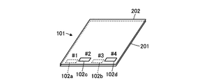
- FIG. 2 is an external view illustrating a configuration example of the mobile terminal according to the embodiment.
- the mobile terminal 101 shown in FIG. 2 includes a main body 201 and a lid 202, and two arrays 102a and 102b are provided in the main body 201 out of the array antennas 102 having four arrays (n). Two more arrays 102 c and 102 d are provided on the lid 202.
- the lid 202 is connected to the main body 201 by a hinge 203, and the lid 202 is foldable. As shown in the figure, when the lid 202 is opened, the arrays 102c and 102d of the lid 202 are separated from the arrays 102a and 102b of the main body 201, and the antenna interval is widened.
- the lid 202 when the lid 202 is closed, the arrays 102c and 102d of the lid 202 approach the arrays 102a and 102b of the main body 201, and the antenna interval becomes narrow.
- the antenna interval is continuously changed between the open state and the closed state.
- the antenna interval detection unit 105 detects the rotation angle of the hinge 203, converts it to an antenna interval, and outputs it. Since the shape of the portable terminal 101 is determined by the rotation angle of the hinge 203, the correlation value between the arrays is determined by the rotation angle of the hinge 203 unless there is anything that scatters radio waves nearby. As described above, when the rotation angle of the hinge 203 is used, the correlation value corresponding to the rotation angle is stored in the portable terminal 101 by measurement or the like in advance, and the correlation value is calculated using the actual rotation angle. The calculation processing for obtaining the correlation value is not required, and the processing processor or the like of the portable terminal 101 is not subjected to a processing load.
- the lid 202 when the lid 202 is closed, the array 102 c of the lid 202 is close to the array 102 a of the main body 201, and the array 102 d of the lid 202 is close to the array 102 b of the main body 201. .
- the RS is transmitted only from one of the adjacent arrays 102a and 102c and one of the arrays 102b and 102d.
- RSs are transmitted from the arrays 102a and 102b of the main body 201, and the number of RS transmissions is “2”.
- the RS interpolation unit 115 of the base station apparatus 110 stores information on the array antenna 102 corresponding to the number of RS transmissions. When the number of RS transmissions is “2”, RSs are transmitted from the arrays 102a and 102b. Get.
- FIG. 3 is a flowchart showing RS transmission processing performed by the mobile terminal on the transmission side.
- the portable terminal 101 executes the following process at least when transmitting user data.
- the antenna interval detector 105 detects the antenna interval (step S301).
- the correlation value measuring unit 106 measures the correlation value of the antenna based on the detected antenna interval (step S302).
- the RS transmission number determination unit 107 determines the RS transmission number according to the obtained correlation value (step S303). At this time, among the array antennas 102 that transmit according to the number of RS transmissions, the array that transmits the RS is determined.
- the RS transmission number determination unit 107 generates the RS transmission number as RS information (step S304).
- the transmission unit 103 transmits the RS information included in the control data from the selected array (step S305). Thereafter, the transmission unit 103 transmits user data using all the arrays of the array antenna 102 (step S306).
- FIG. 4 is a flowchart showing RS reception processing performed by the receiving base station apparatus.
- the receiving unit 113 receives control data via the control channel (step S401).
- the RS is received by the number of RSs transmitted by the mobile terminal 101 on the transmission side.
- RS information extraction part 114 extracts RS information contained in this control data (Step S402).
- the number of RS transmissions of the mobile terminal 101 on the transmission side is extracted.
- the RS interpolation unit 115 performs an RS interpolation process for the array from which the RS is not transmitted based on the extracted number of RS transmissions (step S403).
- the data demodulation unit 116 obtains the channel estimation value obtained from the RS and the interpolated RS. Based on this channel estimation value, user data transmitted from the transmitting-side portable terminal 101 via the user channel is demodulated (and decoded) (step S404).
- the RS interpolation unit 115 identifies the mobile terminal 101 on the transmission side based on the control data. And the number of arrays of the array antenna 102 which the portable terminal 101 has is obtained from RS information. Thereafter, an array that does not transmit RS is obtained based on the number of RS transmissions, and RS interpolation processing is performed on this array. For example, when the lid 202 of the mobile terminal 101 on the transmission side shown in FIG. 2 is closed and the number of RS transmissions is “2”, from the non-adjacent arrays 102a and 102c among the four arrays of the array antenna 102 Assume that RS is transmitted.
- the RS information extraction unit 114 reads the array number setting “4” of the array antenna 102 of the mobile terminal 101 and the received RS transmission number is “2”. It is determined that the data is transmitted from 102c, and it is determined that the arrays to be interpolated are 102b and 102d.
- the array 102b to be interpolated is interpolated based on the RS received by the adjacent array 102a that has received the RS.
- the array 102d is interpolated based on the RS received by the adjacent array 102c that has received the RS.
- the same RS as the arrays 102a and 102b may be used.
- the mobile terminal 101 on the transmission side may add, to the RS information, information on the array that is transmitting the RS or information on the array that is not transmitting the RS.
- the base station apparatus 110 on the receiving side can easily identify the interpolation target array that is not transmitting the RS from the information of the array that is transmitting the RS (or is not transmitting the RS).
- the RS channel can be estimated using the RSs of adjacent (adjacent) arrays that have transmitted the RS. Not limited to this, it is also possible to interpolate using the average value of the RS of the array that has received the RS, or the value obtained by linear interpolation.
- the mobile terminal 101 on the transmission side thins out and transmits the RS with the number of RS transmissions smaller than the number of array antennas 102, and the base station apparatus 110 on the reception side performs interpolation processing for all arrays of the array antenna 102.
- the base station apparatus 110 on the reception side After receiving the user data.
- transmission / reception of main user data can be performed using the optimal number of RS transmissions corresponding to the correlation of the array antenna 102 of the mobile terminal 101 that changes, and transmission power of the mobile terminal 101 can be reduced by not transmitting unnecessary RSs. Can be reduced.
- interference with other base station apparatuses and other portable terminals can be reduced.
- FIG. 5 is a block diagram of a configuration of the mobile terminal according to the second embodiment.
- the second embodiment is a configuration in which the correlation value measurement performed by the mobile terminal 101 on the transmission side is directly obtained from the received signal of the array antenna.
- the antenna interval detection unit 105 is not used.
- a case where the number of arrays of the array antenna 102 of the mobile terminal 101 is “2” will be described as an example. This corresponds to the arrays 102a and 102c in which the antenna interval changes.
- each block component is described outside the mobile terminal 101, but these are provided inside the mobile terminal 101.
- the receiving unit 502 and the transmitting unit 103 are connected to the duplicator (DUP) 501 provided for the number of arrays of the array antenna 102, and the above data is transmitted and received.
- the receiving unit 502 receives the received signals x and y via the arrays 102a and 102c.
- the correlation value measuring unit 106 obtains a correlation value based on the received signals x and y.
- the correlation value z ⁇ x ⁇ y> / ⁇ (
- ) is used. That is, by multiplying the reception level (reception power) of the reception signals x and y received by the arrays 102a and 102c with the radio waves from the base station apparatus 110, an average value ⁇ xy> of the reception power is obtained using an appropriate number of samples. Ask. On the other hand, an average value is also obtained for the root ⁇ (
- the RS transmission number determination unit 107 determines whether or not a predetermined predetermined SN ratio is satisfied based on the correlation value z, and determines the RS transmission number.
- FIG. 6 is a flowchart showing an RS transmission process performed by the mobile terminal on the transmission side.
- the receiving unit 502 measures the reception levels of the arrays 102a and 102c of the array antenna 102 (step S601).
- the correlation value measurement unit 106 obtains a correlation value z between the arrays using the above-described predetermined correlation value formula or the like (step S602).
- the RS transmission number determination unit 107 determines whether or not a required predetermined SN ratio is satisfied based on the correlation value z (step S603). If satisfied (step S603: Yes), the number of RS transmissions is selected such as using a part of the array antenna 102 (step S604). On the other hand, if not satisfied (step S603: No), the RS is transmitted using all the arrays of the array antenna 102 (step S605).
- the mobile terminal 101 determines the number of RS transmissions using the reception level from the base station apparatus 110. At this time, when the state of the array antenna 102 of the mobile terminal 101 is changed, the number of RS transmissions including the change in the state of the propagation path with the mobile terminal 101 using the transmission radio wave from the base station device 110 is determined. is doing. Therefore, conversely, the number of RS transmissions in the mobile terminal 101 is determined on the assumption that the state of the propagation path is the same for transmission from the mobile terminal 101.
- RS information generation step S304
- RS information transmission step S305
- user data transmission step S306
- the RS transmission number is “1” in step S604, the RS transmission number is “2” in step S605, and the RS transmission number is , Switching is performed based on a predetermined S / N ratio.
- the correlation values are obtained for all the combinations, and the above processing is performed for the combinations that maximize the correlation values. Then, the above processing is performed again for the combination having the maximum correlation value with respect to the remaining array, and the number of arrays to transmit the RS is determined by repeating until the correlation value of the remaining array becomes a predetermined threshold value or less. be able to.
- the correlation value is obtained using the reception level of the received signal received by the mobile terminal 101 when the state of the array antenna 102 of the mobile terminal 101 is changed, and the number of RS transmissions at the time of transmission is determined. Used for decision. Thereby, it is possible to transmit the RS with the number of RSs corresponding to the actual state of the mobile terminal 101 and the state of the propagation path at this time without using a special means for detecting the antenna interval.
- 3 is a configuration example in which the transmission format is changed in response to a change in the number of RS transmissions.
- the number of RS transmissions is changed and the array for transmitting the RS is thinned out.
- the array that does not transmit the RS is a period in which the RS is not transmitted.
- the user data transmission format is transmitted as control data.
- the transmission unit 103 transmits this transmission format, and the base station apparatus 110 on the reception side receives the transmission format transmitted from the mobile terminal 101 by the reception unit 113 and converts it into a corresponding reception format. Switch to receive user data.
- FIG. 7 is a flowchart showing RS transmission processing performed by the mobile terminal on the transmission side according to the third embodiment.
- the RS transmission number determination unit 107 determines the RS transmission number (step S303).
- the RS transmission number including the determined RS transmission number is generated as RS information (step S304).
- the transmission unit 103 selects a transmission format corresponding to the number of RS transmissions.
- the transmission format is information such as user data and RS temporal positions in each radio frame, transmission antenna (array), data modulation scheme, error correction code coding rate, and the like.
- the transmission unit 103 transmits the RS information included in the control data from the corresponding array that transmits the RS (step S305). At this time, the transmitting unit 103 transmits information on the transmission format selected using the array that has not transmitted the RS (step S701). Thereafter, the transmission unit 103 transmits user data using all arrays in the selected transmission format (step S306).
- the modulation scheme of the modulation unit 104 provided in the transmission unit 103 is changed.
- a modulation scheme with better noise characteristics excellent SN ratio
- FIG. 8 is a flowchart showing RS reception processing performed by the receiving base station apparatus according to the third embodiment.
- the receiving unit 113 receives the RS information transmitted from the mobile terminal 101 on the transmission side (step S401) and receives the transmission format (step S802). Depending on the configuration of the reception unit 113, the reception process may be performed in step S ⁇ b> 802 after the reception process in step S ⁇ b> 401 as illustrated.
- the RS interpolation unit 115 performs RS interpolation processing for the array from which RS is not transmitted based on the received RS transmission number (step S403).
- the data demodulation unit 116 obtains the channel estimation value obtained from the RS and the interpolated RS.
- user data transmitted from the transmitting-side portable terminal 101 via the user channel is demodulated (and decoded) (step S404).
- the reception unit 113 and the data demodulation unit 116 switch to a reception format corresponding to the transmission format received in step S802 and receive user data. Not only switching of the reception format in the reception unit 113, but also the coding method at the time of data demodulation in the data demodulation unit 116 can be switched.
- the mobile terminal 101 on the transmission side is configured to transmit a transmission format using an array that does not transmit an RS, it is possible to improve data transmission efficiency.
- FIG. 9 is a block diagram showing a configuration of a receiving-side base station apparatus according to the fourth embodiment.
- the mobile terminal 101 on the transmission side obtains the correlation value between the antennas and determines the array for transmitting the RS.
- the base station apparatus 110 performs this processing.
- the configuration of the correlation value measuring unit 106 and the RS transmission number determining unit 107 described in FIG. In FIG. 9, a configuration mainly related to determination of the number of RS transmissions in the base station apparatus 110 is described.
- the configuration on the mobile terminal 101 side is omitted, but the correlation value measuring unit 106 and the RS transmission number determining unit 107 are omitted from the configuration shown in FIG.
- the duplicator (DUP) 501 is connected to a receiving unit 113 and a transmitting unit 901, and transmits and receives data to and from the mobile terminal 101.
- the mobile terminal 101 transmits RSs from the two arrays 102a and 102c in the same manner as described above, and the reception unit 113 of the base station apparatus 110 receives the RS reception signals x and y from the terminals via the antenna 112.
- the correlation value measuring unit 106 obtains a correlation value based on the received signals x and y.
- the correlation value z ⁇ x ⁇ y> / ⁇ (
- ) is used. That is, an appropriate number of samples is obtained by multiplying the reception levels (reception power) of the reception signals x and y when the RS transmitted from the arrays 102a and 102c of the mobile terminal 101 on the transmission side is received by the base station device 110, respectively. To determine the average value ⁇ xy> of received power. On the other hand, an average value is also obtained for the root ⁇ (
- the RS transmission number determination unit 107 determines whether or not a predetermined predetermined SN ratio is satisfied based on the correlation value z, and determines the RS transmission number. The determined RS transmission number is transmitted to the mobile terminal 101 via the transmission unit 901.
- the correlation value measurement unit 106 creates a correlation matrix for each subcarrier capable of receiving RS, obtains the correlation for each subcarrier, A correlation value is obtained by comparing an average error or a maximum error with a reference value.
- CDMA Code Division Multiple Access
- FIG. 10 is a flowchart showing the RS transmission number determination process performed by the base station apparatus.
- the receiving unit 113 measures the reception levels of the arrays 102a and 102c of the array antenna 102 of the mobile terminal 101 (step S601).
- the correlation value measurement unit 106 obtains a correlation value z between the arrays using the above-described predetermined correlation value formula or the like (step S602).
- the RS transmission number determination unit 107 determines whether or not a required predetermined SN ratio is satisfied based on the correlation value z (step S603). If satisfied (step S603: Yes), the number of RS transmissions is selected such as using a part of the array antenna 102 of the mobile terminal 101 (step S604).
- step S603 if not satisfied (step S603: No), the number of RS transmissions is set to all arrays of the array antenna 102 (step S1005). Then, after the RS information is generated (step S304), the RS information is transmitted to the mobile terminal 101 (step S305).
- the number of RS transmissions in the mobile terminal 101 is determined using the RS reception level from the mobile terminal 101 in the base station apparatus 110.
- the number of RS transmissions is determined including a change in the state of the propagation path with the base station apparatus 110 using the transmission radio wave from the mobile terminal 101. is doing.
- the number of RS transmissions is “1” in step S604, the number of RS transmissions is “2” in step S605, and RS Will be switched based on a predetermined S / N ratio.
- the correlation values are obtained for all the combinations, and the above processing is performed for the combinations that maximize the correlation values. Then, the above processing is performed again for the combination having the maximum correlation value with respect to the remaining array, and the number of arrays to transmit the RS is determined by repeating until the correlation value of the remaining array becomes a predetermined threshold value or less. be able to.
- FIG. 11 is a flowchart showing RS transmission processing performed by the mobile terminal.
- RS information including the RS transmission number determined by the base station apparatus 110 is received by the receiving unit 502 of the mobile terminal 101 (step S1101), and the transmitting unit 103 determines a transmission format corresponding to the RS transmission number (step S1101).
- S1102) RS is transmitted from the array corresponding to the RS transmission number (step S1103).
- the transmission unit 103 transmits user data using all arrays in the selected transmission format (step S1104).
- the modulation scheme of the modulation unit 104 provided in the transmission unit 103 is changed.
- the processing burden on the mobile terminal 101 side can be reduced.
- FIG. 12A is an external view showing a state where the mobile terminal is opened
- FIG. 12B is an external view showing a state where the mobile terminal is closed.
- a main body 201 and a lid 202 are provided, and an array number (n) is provided with four array antennas 102.
- the two arrays 102c and 102d provided on the lid 202 are displaced with respect to the two arrays 102a and 102b provided on the main body 201. Even if the lid 202 is closed, all the arrays 102a and 102b are disposed.
- the arrays 102a to 102d are configured so as not to overlap each other.
- the antenna interval is sufficiently wide and the RSs are transmitted from all the four arrays 102a to 102d.
- RS is transmitted from two arrays selected from the four arrays 102a to 102d when the lid 202 is closed.
- FIG. 13 is a chart showing examples of combination patterns according to the number of RS transmissions.
- the RS transmission number determination unit 107 includes a storage unit that stores the illustrated RS combination information 1301. In the illustrated combination information 1301, when the RS transmission number is “1”, the RS is transmitted only by the array # 1 (102 a). When the RS transmission number is “2”, the RS is transmitted from the arrays # 1 (102a) and # 3 (102b). When the number of RS transmissions is “3”, RSs are transmitted from the arrays # 1 (102a), # 2 (102c), and # 3 (102b). If the RS transmission number is “4”, RSs are transmitted from all arrays # 1 to # 4 (102a to 102d).
- the RS combination information 1301 is configured to be stored in the storage unit (not shown) by the RS information extraction unit 114 on the base station apparatus 110 side by transmission from the mobile terminal 101 or the like.
- the mobile terminal 101 by sharing the RS combination information corresponding to the number of RS transmissions between the mobile terminal 101 and the base station device 110, it is possible to reduce the information for identifying the array transmitting the RS among the RS information. .
- the tabulated RS combination information as shown in FIG. 13 the mobile terminal 101 only needs to transmit one of the four RS transmission numbers “1” to “4”. Only 2 bits are required.
- the RS transmission number receives any one of “1” to “4”, and the RS information extraction unit 114 is based on the same RS combination information shown in FIG. The combination of the arrays 102a to 102d that transmitted the RS can be specified.
- FIG. 14 is a flowchart showing RS transmission processing using RS combination information in the mobile terminal.
- the mobile terminal 101 creates the RS combination information 1301 described above (step S1401), and transmits the created RS combination information 1301 to the base station apparatus 110 (step S1402).
- the setting up to this point is a prior setting, and the portable terminal 101 may transmit once as long as the arrangement of the arrays 102a to 102d of the array antenna 102 does not change.
- the subsequent processing is almost the same as in the above embodiment.
- the correlation value measuring unit 106 measures the correlation value (step S302), and the RS transmission number determining unit 107 determines the RS transmission number (step S303) and generates RS information (step S304).
- RS information one of the RS transmission numbers “1” to “4” indicating which of the RS combination information 1301 is transmitted in 2 bits (step S305).
- the transmission part 103 determines the transmission format corresponding to the RS transmission number (step S1102), and transmits RS from the array corresponding to the RS transmission number (step S1103). Thereafter, the transmission unit 103 transmits user data using all arrays in the selected transmission format (step S1104).
- FIG. 15 is a flowchart showing RS reception processing using RS combination information in the base station apparatus.
- the base station apparatus 110 receives the RS combination information 1301 transmitted from the mobile terminal 101 (step S1501)
- the base station apparatus 110 stores the RS combination information 1301 in the storage unit of the RS information extraction unit 114 (step S1502).
- the receiving unit 113 receives the RS information transmitted from the mobile terminal 101 on the transmission side (step S401).
- This RS information is any one of the above-mentioned 2-bit RS transmission numbers “1” to “4”.
- the RS information extraction unit 114 can read the RS combination information 1301 stored in the storage unit and specify the array of the mobile terminals 101 corresponding to the RS transmission number.
- the transmission format is received (step S802), and the RS interpolation unit 115 performs RS interpolation processing for the array to which the RS specified by the received number of RS transmissions is not transmitted (step S403).
- the data demodulation unit 116 obtains the channel estimation value obtained from the RS and the interpolated RS. Based on this channel estimation value, user data transmitted from the transmission-side portable terminal 101 via the user channel is demodulated and decoded (step S404). At this time, the reception unit 113 and the data demodulation unit 116 switch to a reception format corresponding to the transmission format received in step S802 and receive user data.
- the RS combination information 1301 described in the fifth embodiment it is not necessary to transmit the information of the array transmitting the RS every time the RS is transmitted from the mobile terminal 101, and the RS is configured with a small number of bits. Therefore, it is possible to notify the array that is transmitting, so that an increase in overhead can be prevented.
- the RS combination information 1301 is transmitted from the mobile terminal 101 to the base station apparatus 100, but the present invention is not limited to this.
- This RS combination information 1301 can be input to the base station apparatus 110 by itself or set in the base station apparatus 110 via a host apparatus.
- the mobile terminal 101 can omit creation of the RS combination information 1301 and transmission to the base station apparatus 110.
- the RS combination information 1301 may be transmitted from the base station apparatus 110 to the mobile terminal 101 and stored in the mobile terminal 11.
- FIGS. 16-1 to 16-3 are external views showing open / closed states of the mobile terminal for explaining RS interpolation.
- 16-1 shows a state in which the lid 202 of the mobile terminal 101 is opened widely
- FIG. 16-2 shows a state in which the cover 202 is slightly opened
- FIG. 16-3 shows a state in which it is closed.
- the RS transmission number determination unit 107 obtains a formula and a coefficient used for RS interpolation corresponding to the change in the antenna interval, and transmits them to the RS interpolation unit 115 of the base station apparatus 110.
- the RS is transmitted from all the arrays # 1 (102a) to # 4 (102d) of the array antenna 102. It is not necessary to perform.
- FIG. 16B it is assumed that the RS is not transmitted from the array # 4 (102d) when the lid 202 is slightly opened. At this time, it is assumed that the RS reception levels of the respective arrays # 1 (102a) to # 3 (102b) are h1, h2, and h3. When viewed from the arrays # 1 (102a) to # 4 (102d), these are arranged at the four corners of the parallelogram.
- the RS transmission number determination unit 107 transmits these interpolation formulas and coefficients included in the RS information.
- an interpolation formula and coefficient of h4 ⁇ 0.5 ⁇ h1 + 1.5 ⁇ h2 (external dividing point) are transmitted.
- the RS interpolation unit 115 switches between the interpolation formula and the coefficient according to the number of RS transmissions and transmits the RS.
- three types of change states are used.
- the coefficients 0.5, 1 and 2) correspond to the continuous change of the rotation angle. .5, ⁇ , etc.
- FIG. 17 is a flowchart showing an RS transmission process including RS interpolation information transmission in the mobile terminal.
- Correlation value measurement section 106 measures the correlation value of the antenna (step S302), and RS transmission number determination section 107 determines the number of RS transmissions according to the obtained correlation value (step S303).
- the array that transmits the RS is determined.
- the interpolation formula and coefficient are determined (step S1701).
- the RS transmission number determination unit 107 generates RS information including the interpolation formula and the coefficient (step S304).
- the transmission unit 103 transmits the RS information included in the control data from the selected array (step S305). Then, the transmission format corresponding to the RS transmission number is determined (step S1102), and the RS is transmitted from the array corresponding to the RS transmission number (step S1103). Thereafter, the transmission unit 103 transmits user data using all arrays in the selected transmission format (step S1104).
- FIG. 18 is a flowchart showing RS reception processing including information reception of RS interpolation in the base station apparatus.
- the receiving unit 113 receives control data via the control channel and extracts RS information (step S401). Also, the transmission format is received (step S802). Then, the RS information extraction unit 114 extracts an interpolation formula and a coefficient in the mobile terminal 101 on the transmission side from the RS information included in the control data (step S1801). Next, the RS interpolation unit 115 performs an RS interpolation process for the array to which the RS is not transmitted using the interpolation formula and the coefficient (Step S403).
- the data demodulation unit 116 obtains the channel estimation value obtained from the RS and the interpolated RS. Based on this channel estimation value, user data transmitted from the transmitting-side portable terminal 101 via the user channel is demodulated (and decoded) (step S804). At this time, the reception unit 113 and the data demodulation unit 116 switch to a reception format corresponding to the transmission format received in step S802 and receive user data.
- mobile terminal 101 transmits an interpolation equation coefficient to a base station after determining an array for transmitting RS, and base station apparatus 110 performs interpolation at a time prior to RS interpolation processing. Receive formulas and coefficients. By this procedure, more accurate RS interpolation can be performed, and wireless transmission performance is improved.
- the interpolation formula and the coefficient are first transmitted to the base station apparatus 110, but after that, when the shape of the mobile terminal 101 changes and the antenna interval is changed (correlation). A configuration may be adopted in which only the coefficient after the change is transmitted when the value changes).
- the disclosed technique even if the antenna interval of the transmission apparatus changes, an optimal array is selected in response to this change, and a pilot signal can be transmitted. Thereby, overhead can be suppressed and transmission efficiency can be improved. Further, since the antenna interpolation corresponding to the change of the antenna interval of the transmitting device can be performed on the receiving device side, the communication quality can be improved.
Abstract
A transmission-side mobile terminal (101) is provided with: a transmission unit (103) wherein array intervals for an array antenna (102) can be changed by switching and which transmits a pilot signal using a selected array based on a correlation value between a plurality of antennas; and an RS transmission number determination unit (107) which selects from a plurality of array antennas (102) an array antenna (102) for transmitting the pilot signal, based on the correlation value, and generates this antenna selection information. The transmission unit (103) transmits the antenna selection information to a reception-side base station device (110) and also transmits the pilot signal by using the selected array antenna (102).
Description
この発明は、無線通信を行う無線機器、例えば、多数のアンテナを備えた無線機器のパイロット信号を送受信する送信装置、受信装置、無線通信システムおよび無線通信方法に関する。
The present invention relates to a transmission device, a reception device, a wireless communication system, and a wireless communication method for transmitting and receiving pilot signals of a wireless device that performs wireless communication, for example, a wireless device including a plurality of antennas.
送信側と受信側を同期させる同期通信システムでは、送信側から送信アンテナ毎にパイロット信号(RS:Reference Signal)を送信し、受信側ではRSに基づいて伝搬路推定の処理を行っている。近年の無線通信では、MIMO(Multiple Input Multiple Output)など、複数のアンテナを用いる方式が提案されている。この方式では、各送信アンテナ毎の伝播チャネルを得るために、各アンテナ毎にRSを送信する。この場合、あるアンテナでRSを送信している瞬間は、他のアンテナでは何も送信することができず、送信アンテナの数が増えるにしたがい、データ以外のRSを送信するためのオーバヘッドが増大し伝送効率が低下する。
In a synchronous communication system that synchronizes the transmission side and the reception side, a pilot signal (RS: Reference Signal) is transmitted from the transmission side for each transmission antenna, and the reception side performs propagation path estimation processing based on the RS. In recent wireless communication, a scheme using a plurality of antennas such as MIMO (Multiple Input Multiple Output) has been proposed. In this scheme, an RS is transmitted for each antenna in order to obtain a propagation channel for each transmission antenna. In this case, at the moment when an RS is transmitted by a certain antenna, nothing can be transmitted by another antenna, and as the number of transmission antennas increases, the overhead for transmitting an RS other than data increases. Transmission efficiency decreases.
そこで、RSの送信量を減らすために、複数のうち一部のアンテナからだけRSを送信する方法が考えられている。例えば、送信側のアンテナの間隔が非常に近い場合は、伝搬路の相関が大きいため、送信側では一部のアンテナからRSを送信し、受信側ではRSを送信した以外のアンテナの伝搬路を補間処理で推定することにより、データの送信効率を上げる方式が知られている(例えば、下記特許文献1参照。)。
Therefore, in order to reduce the amount of RS transmission, a method of transmitting the RS only from some of the antennas is considered. For example, when the distance between the antennas on the transmitting side is very close, the correlation between the propagation paths is large, so the RS transmits the RS from some antennas on the transmitting side, and the antennas other than the RS transmitting on the receiving side. A method is known in which the data transmission efficiency is increased by estimation by interpolation processing (see, for example, Patent Document 1 below).
送信側が小型の携帯端末の場合であることを考えると、アンテナ設置場所に限度があり、アンテナの間隔が狭くなりやすいため、上記のようにRSを間引きする方法も有効であると考えられる。しかし、携帯端末の場合は、端末の形状の変化によりアンテナの間隔が変化するものがある。例えば、折り畳み形状やスライド形状の携帯端末では、閉じたときと開いたときとではアンテナ間の距離が異なり、アンテナの相関が変化する。具体的には、携帯端末を開いたときには、アンテナ間隔が広がり相関が小さくなり、閉じたときにはアンテナ間隔が接近し相関が大きくなる。このため、形状が変化する携帯端末の場合、送信側でRS送信数を固定にすると最適なRS送信数ではなくなる。このような携帯端末としては、携帯電話機、PDA、可搬型パーソナルコンピュータ等が挙げられる。
Considering that the transmitting side is a small mobile terminal, there is a limit to the antenna installation location, and the distance between the antennas tends to be narrowed. Therefore, it is considered that the method of thinning out the RS as described above is also effective. However, in the case of a mobile terminal, there is a mobile terminal whose antenna interval changes due to a change in the shape of the terminal. For example, in a folded or slide-shaped portable terminal, the distance between the antennas differs between when it is closed and when it is opened, and the correlation of the antennas changes. Specifically, when the mobile terminal is opened, the antenna interval widens and the correlation decreases, and when the mobile terminal is closed, the antenna interval approaches and the correlation increases. For this reason, in the case of a mobile terminal whose shape changes, if the number of RS transmissions is fixed on the transmission side, the number of RS transmissions is not optimal. Examples of such portable terminals include mobile phones, PDAs, and portable personal computers.
このように、従来は、送信側では、携帯端末のアンテナの相関が変化しても対応した最適なRS送信数で送信できず、不要なアンテナからのRSの送信があってもこれを抑制できず、不要なRSの送信のために送信電力を低減化できず、他の受信側(基地局)や他の携帯端末への干渉も生じるおそれがあった。特に、送信側が携帯端末のときには、形状変化でアンテナの相関が変化するが、これに対応できず、最適なRS送信数を用いた主要なデータの送受信が行えなかった。受信側でも、最適なRS送信数が不明であると、正確なアンテナ補間が行えず、伝送効率および品質を向上できない。
Thus, conventionally, on the transmission side, even if the correlation of the antenna of the mobile terminal changes, it is not possible to transmit with the optimal number of RS transmissions corresponding to it, and this can be suppressed even if there is RS transmission from an unnecessary antenna. Therefore, the transmission power cannot be reduced due to unnecessary RS transmission, and interference with other reception side (base station) and other portable terminals may occur. In particular, when the transmitting side is a portable terminal, the correlation of the antenna changes due to the shape change, but this cannot cope with this, and main data transmission / reception using the optimal number of RS transmissions cannot be performed. Even on the receiving side, if the optimal number of RS transmissions is unknown, accurate antenna interpolation cannot be performed, and transmission efficiency and quality cannot be improved.
開示の技術は、送信側でのパイロット信号を送信するアンテナ数の変化に受信側が対応でき、伝送効率及び品質を向上できることを目的とする。
The disclosed technique aims to improve the transmission efficiency and quality by allowing the receiving side to cope with a change in the number of antennas transmitting pilot signals on the transmitting side.
上述した課題を解決し、目的を達成するため、開示技術は、アンテナ間隔が変更可能な複数のアンテナと、複数の前記アンテナ間の相関値に基づき、複数の前記アンテナから選択されたアンテナを用いてパイロット信号を送信する送信部と、を備える。
In order to solve the above-described problems and achieve the object, the disclosed technology uses a plurality of antennas whose antenna intervals can be changed, and an antenna selected from the plurality of antennas based on correlation values between the plurality of antennas. And a transmitter for transmitting the pilot signal.
開示の送信装置、受信装置、無線通信システムおよび無線通信方法によれば、送信側でのパイロット信号を送信するアンテナ数の変化に受信側が対応でき、伝送効率及び品質を向上できるという効果を奏する。
According to the disclosed transmission device, reception device, wireless communication system, and wireless communication method, the reception side can cope with a change in the number of antennas that transmit pilot signals on the transmission side, and the transmission efficiency and quality can be improved.
以下に添付図面を参照して、開示技術の好適な実施の形態を詳細に説明する。開示技術は、例えば、形状が変化する携帯端末に適用し、端末の形状の変化に応じてアレイアンテナのうち使用するアレイを切り替えることにより、変化後の形状に応じて適切なアレイからRSを送信するものである。以下の各実施の形態では、送信側が携帯端末101であり、受信側が基地局装置110であるとし、この送信側の携帯端末101におけるアンテナ間隔の変更に伴い、RSを送信するアレイの数(RS送信数)を選択および変更するものとして説明する。
Hereinafter, preferred embodiments of the disclosed technology will be described in detail with reference to the accompanying drawings. The disclosed technology is applied to, for example, a portable terminal whose shape changes, and by switching the array to be used among the array antennas according to the change in the shape of the terminal, the RS is transmitted from an appropriate array according to the changed shape. To do. In each of the following embodiments, it is assumed that the transmitting side is the mobile terminal 101 and the receiving side is the base station apparatus 110, and the number of arrays (RS A description will be given assuming that the number of transmissions is selected and changed.
(実施の形態1)
図1は、実施の形態1にかかる通信システムの構成を示すブロック図である。この通信システム100は、携帯端末101および基地局装置110を備えている。携帯端末101は、アレイアンテナ102と、このアレイアンテナ102を介してデータを送信する送信部103とを備える。アレイアンテナ102は、複数nのアレイ102a~102nを有している。送信部103は変調部104を有し、変調部104の変調方式でユーザデータおよび制御データを送信する。また、複数のアレイアンテナ102は、パイロット信号RSと、RS情報を制御データに含ませ、制御チャネルを使用して選択したRS送信用のアレイから送信する。 (Embodiment 1)
FIG. 1 is a block diagram of a configuration of the communication system according to the first embodiment. Thecommunication system 100 includes a mobile terminal 101 and a base station device 110. The mobile terminal 101 includes an array antenna 102 and a transmission unit 103 that transmits data via the array antenna 102. The array antenna 102 has a plurality of n arrays 102a to 102n. The transmission unit 103 includes a modulation unit 104 and transmits user data and control data using the modulation scheme of the modulation unit 104. The plurality of array antennas 102 include the pilot signal RS and RS information in the control data, and transmit from the RS transmission array selected using the control channel.
図1は、実施の形態1にかかる通信システムの構成を示すブロック図である。この通信システム100は、携帯端末101および基地局装置110を備えている。携帯端末101は、アレイアンテナ102と、このアレイアンテナ102を介してデータを送信する送信部103とを備える。アレイアンテナ102は、複数nのアレイ102a~102nを有している。送信部103は変調部104を有し、変調部104の変調方式でユーザデータおよび制御データを送信する。また、複数のアレイアンテナ102は、パイロット信号RSと、RS情報を制御データに含ませ、制御チャネルを使用して選択したRS送信用のアレイから送信する。 (Embodiment 1)
FIG. 1 is a block diagram of a configuration of the communication system according to the first embodiment. The
RS送信用アンテナとして選択する特定のアレイは、アンテナ間隔に基づき決定される。このアンテナ間隔はアンテナ間隔検出部105により検出される。相関値測定部106は、検出されたアンテナ間隔に対応する相関値を測定する。RS送信数決定部107は、測定された相関値に対応する送信のRS送信数を決定する。RS送信数決定部107は、決定したRS送信数に基づきアレイアンテナ102の中からRS送信数に基づき特定のアレイを選択し、選択したアレイをRS送信用のアレイとする。
The specific array to select as the RS transmitting antenna is determined based on the antenna spacing. This antenna interval is detected by the antenna interval detection unit 105. The correlation value measurement unit 106 measures a correlation value corresponding to the detected antenna interval. The RS transmission number determination unit 107 determines the number of RS transmissions of transmission corresponding to the measured correlation value. The RS transmission number determination unit 107 selects a specific array based on the RS transmission number from the array antenna 102 based on the determined RS transmission number, and sets the selected array as an array for RS transmission.
この際、アレイアンテナ102のアレイのうち少なくとも近接(あるいは隣接)するアレイは選択せず、所定のアレイ数毎に間引きして選択する。そして、RS送信数決定部107は、制御データの一部にRSと、RS情報を含ませる。なお、不図示であるが送信部103には携帯端末101のユーザ操作によるユーザデータが入力され、変調部104の変調によりユーザチャネルを介してアレイアンテナ102から基地局装置110にデータ送信される。
At this time, at least the adjacent (or adjacent) arrays are not selected from the array of the array antenna 102, but are selected by thinning out every predetermined number of arrays. And RS transmission number determination part 107 includes RS and RS information in a part of control data. Although not shown, user data by a user operation of the mobile terminal 101 is input to the transmission unit 103, and data is transmitted from the array antenna 102 to the base station apparatus 110 via the user channel by modulation of the modulation unit 104.
基地局装置110は、アンテナ112を備えており、受信部113は制御データおよびユーザデータを受信する。RS情報抽出部114は、制御データに含まれるRS情報からRS送信数を抽出する。RS補間部115は、携帯端末101においてRSを送信しないアレイについてRSの補間処理を行う。このため、RS補間部115には、送信側の携帯端末101についてのアレイアンテナ102の情報があらかじめ設定されている。具体的には、携帯端末101が有するアレイアンテナ102のアレイ数と、RS送信数に対応したアレイの情報が設定されている。データ復調部116は、RSと、補間されたRSで求めたチャネル推定値を用いて、ユーザデータを復調、復号する。なお、基地局装置110のアンテナ112は、複数nのアレイ112a~112nを有するアレイアンテナであってもよい。
The base station apparatus 110 includes an antenna 112, and the reception unit 113 receives control data and user data. The RS information extraction unit 114 extracts the number of RS transmissions from the RS information included in the control data. The RS interpolation unit 115 performs RS interpolation processing on the array that does not transmit RS in the mobile terminal 101. For this reason, in the RS interpolation unit 115, information on the array antenna 102 for the mobile terminal 101 on the transmission side is set in advance. Specifically, the array information corresponding to the number of arrays of the array antenna 102 included in the mobile terminal 101 and the number of RS transmissions is set. The data demodulation unit 116 demodulates and decodes user data using the RS and the channel estimation value obtained from the interpolated RS. Note that the antenna 112 of the base station apparatus 110 may be an array antenna having a plurality of n arrays 112a to 112n.
図1に示した携帯端末101の相関値測定部106,RS送信数決定部107等が行う演算処理は、携帯端末101に設けられた通信処理用の処理プロセッサ(CPU)などが行う通信処理の機能に加えて、相関値測定およびRS数決定にかかる所定のプログラムを実行することにより実現できる。同様に、基地局装置110のRS情報抽出部114,RS補間部115,データ復調部116等についても同様に通信処理用の処理プロセッサを用いて構成できる。
The arithmetic processing performed by the correlation value measuring unit 106, the RS transmission number determining unit 107, and the like of the mobile terminal 101 illustrated in FIG. 1 is the communication processing performed by the processing processor (CPU) for communication processing provided in the mobile terminal 101. In addition to the function, it can be realized by executing a predetermined program related to correlation value measurement and RS number determination. Similarly, the RS information extraction unit 114, the RS interpolation unit 115, the data demodulation unit 116, and the like of the base station apparatus 110 can be similarly configured using a processing processor for communication processing.
図2は、実施の形態にかかる携帯端末の構成例を示す外観図である。図2に示す携帯端末101は、本体201と、蓋体202を備えており、アレイ数(n)が4本のアレイアンテナ102のうち、2本のアレイ102a,102bが本体201に設けられ、もう2本のアレイ102c、102dが蓋体202に設けられている。本体201に対し蓋体202はヒンジ203で接続され、蓋体202が折り畳み自在である。図示のように、蓋体202を開いた状態では、本体201のアレイ102a、102bに対して、蓋体202のアレイ102c,102dが離れ、アンテナ間隔が広くなる。逆に蓋体202を閉じた状態では、本体201のアレイ102a、102bに対して、蓋体202のアレイ102c,102dが接近し、アンテナ間隔が狭くなる。これら開いた状態と閉じた状態の間においてアンテナ間隔は連続的に変更されることになる。
FIG. 2 is an external view illustrating a configuration example of the mobile terminal according to the embodiment. The mobile terminal 101 shown in FIG. 2 includes a main body 201 and a lid 202, and two arrays 102a and 102b are provided in the main body 201 out of the array antennas 102 having four arrays (n). Two more arrays 102 c and 102 d are provided on the lid 202. The lid 202 is connected to the main body 201 by a hinge 203, and the lid 202 is foldable. As shown in the figure, when the lid 202 is opened, the arrays 102c and 102d of the lid 202 are separated from the arrays 102a and 102b of the main body 201, and the antenna interval is widened. Conversely, when the lid 202 is closed, the arrays 102c and 102d of the lid 202 approach the arrays 102a and 102b of the main body 201, and the antenna interval becomes narrow. The antenna interval is continuously changed between the open state and the closed state.
アンテナ間隔検出部105は、図示の例では、ヒンジ203の回動角度を検出し、アンテナの間隔に換算して出力する。携帯端末101の形状は、ヒンジ203の回動角度により決まるので、近くに電波を散乱するものがなければ、アレイ間の相関値はヒンジ203の回動角度により決まる。このように、ヒンジ203の回動角度を利用する場合、あらかじめ回動角度に対応した相関値を測定等により携帯端末101に記憶しておくことにより、実際の回動角度を用いて相関値を得ることができ、相関値を求める演算処理を行わずに済み携帯端末101の演算プロセッサ等に処理負担を掛けることがない。
In the illustrated example, the antenna interval detection unit 105 detects the rotation angle of the hinge 203, converts it to an antenna interval, and outputs it. Since the shape of the portable terminal 101 is determined by the rotation angle of the hinge 203, the correlation value between the arrays is determined by the rotation angle of the hinge 203 unless there is anything that scatters radio waves nearby. As described above, when the rotation angle of the hinge 203 is used, the correlation value corresponding to the rotation angle is stored in the portable terminal 101 by measurement or the like in advance, and the correlation value is calculated using the actual rotation angle. The calculation processing for obtaining the correlation value is not required, and the processing processor or the like of the portable terminal 101 is not subjected to a processing load.
例えば、図2の構成例の場合、蓋体202を閉じた状態では、本体201のアレイ102aに蓋体202のアレイ102cが近接し、本体201のアレイ102bに蓋体202のアレイ102dが近接する。この状態では、近接するアレイ102a,102cの一方、およびアレイ102b、102dの一方からだけRSを送信する。蓋体202を閉じた状態のとき、本体201のアレイ102a,102bからRSを送信し、RS送信数が「2」となる。基地局装置110のRS補間部115には、RS送信数に対応したアレイアンテナ102の情報が格納されており、RS送信数が「2」のときアレイ102a,102bからRSが送信されていることを得る。
For example, in the configuration example of FIG. 2, when the lid 202 is closed, the array 102 c of the lid 202 is close to the array 102 a of the main body 201, and the array 102 d of the lid 202 is close to the array 102 b of the main body 201. . In this state, the RS is transmitted only from one of the adjacent arrays 102a and 102c and one of the arrays 102b and 102d. When the lid 202 is in a closed state, RSs are transmitted from the arrays 102a and 102b of the main body 201, and the number of RS transmissions is “2”. The RS interpolation unit 115 of the base station apparatus 110 stores information on the array antenna 102 corresponding to the number of RS transmissions. When the number of RS transmissions is “2”, RSs are transmitted from the arrays 102a and 102b. Get.
図3は、送信側の携帯端末が行うRS送信処理を示すフローチャートである。携帯端末101は、少なくともユーザデータの送信時に以下の処理を実行する。アンテナ間隔検出部105はアンテナ間隔を検出する(ステップS301)。相関値測定部106は、検出されたアンテナ間隔に基づき、アンテナの相関値を測定する(ステップS302)。RS送信数決定部107は、得られた相関値に応じてRS送信数を決定する(ステップS303)。この際、RS送信数に応じて送信するアレイアンテナ102のうち、RSを送信するアレイが決定される。RS送信数決定部107は、RS送信数をRS情報として生成する(ステップS304)。
FIG. 3 is a flowchart showing RS transmission processing performed by the mobile terminal on the transmission side. The portable terminal 101 executes the following process at least when transmitting user data. The antenna interval detector 105 detects the antenna interval (step S301). The correlation value measuring unit 106 measures the correlation value of the antenna based on the detected antenna interval (step S302). The RS transmission number determination unit 107 determines the RS transmission number according to the obtained correlation value (step S303). At this time, among the array antennas 102 that transmit according to the number of RS transmissions, the array that transmits the RS is determined. The RS transmission number determination unit 107 generates the RS transmission number as RS information (step S304).
送信部103は、RS情報を選択したアレイから制御データに含ませて送信する(ステップS305)。この後、送信部103は、アレイアンテナ102の全てのアレイを用いてユーザデータを送信する(ステップS306)。
The transmission unit 103 transmits the RS information included in the control data from the selected array (step S305). Thereafter, the transmission unit 103 transmits user data using all the arrays of the array antenna 102 (step S306).
図4は、受信側の基地局装置が行うRS受信処理を示すフローチャートである。基地局装置110では、受信部113が制御チャネルを介して制御データを受信する(ステップS401)。この受信時、送信側の携帯端末101が送信したRS数でRSを受信することになる。そしてRS情報抽出部114は、この制御データに含まれるRS情報を抽出する(ステップS402)。この際、送信側の携帯端末101のRS送信数を抽出する。次に、RS補間部115は、抽出したRS送信数からRSが送信されないアレイについてのRSの補間処理を行う(ステップS403)。この後、データ復調部116は、RSと、補間されたRSで求めたチャネル推定値を求める。このチャネル推定値に基づいて、送信側の携帯端末101からユーザチャネルを介して送信されてくるユーザデータを復調(および復号)する(ステップS404)。
FIG. 4 is a flowchart showing RS reception processing performed by the receiving base station apparatus. In the base station apparatus 110, the receiving unit 113 receives control data via the control channel (step S401). At the time of reception, the RS is received by the number of RSs transmitted by the mobile terminal 101 on the transmission side. And RS information extraction part 114 extracts RS information contained in this control data (Step S402). At this time, the number of RS transmissions of the mobile terminal 101 on the transmission side is extracted. Next, the RS interpolation unit 115 performs an RS interpolation process for the array from which the RS is not transmitted based on the extracted number of RS transmissions (step S403). Thereafter, the data demodulation unit 116 obtains the channel estimation value obtained from the RS and the interpolated RS. Based on this channel estimation value, user data transmitted from the transmitting-side portable terminal 101 via the user channel is demodulated (and decoded) (step S404).
上記のRS補間処理について説明する。RS補間部115は、ステップS403において、制御データに基づき送信側の携帯端末101を特定する。そして、RS情報から携帯端末101が有するアレイアンテナ102のアレイ数を得る。この後、RS送信数に基づきRSを送信していないアレイを求め、このアレイについてRSの補間処理を行う。例えば、図2に示した送信側の携帯端末101の蓋体202が閉じられたとき、RS送信数を「2」としたとき、アレイアンテナ102のアレイ4本のうち隣接しないアレイ102a,102cからRSを送信するとする。基地局装置110では、RS情報抽出部114が携帯端末101のアレイアンテナ102のアレイ数の設定「4」を読み出し、また受信したRS送信数が「2」であることから、RSがアレイ102a,102cから送信されていると判断し、補間対象となるアレイが102b、102dであると判断する。
The RS interpolation process will be described. In step S403, the RS interpolation unit 115 identifies the mobile terminal 101 on the transmission side based on the control data. And the number of arrays of the array antenna 102 which the portable terminal 101 has is obtained from RS information. Thereafter, an array that does not transmit RS is obtained based on the number of RS transmissions, and RS interpolation processing is performed on this array. For example, when the lid 202 of the mobile terminal 101 on the transmission side shown in FIG. 2 is closed and the number of RS transmissions is “2”, from the non-adjacent arrays 102a and 102c among the four arrays of the array antenna 102 Assume that RS is transmitted. In the base station apparatus 110, the RS information extraction unit 114 reads the array number setting “4” of the array antenna 102 of the mobile terminal 101 and the received RS transmission number is “2”. It is determined that the data is transmitted from 102c, and it is determined that the arrays to be interpolated are 102b and 102d.
補間処理については、例えば、補間対象となるアレイ102bについては、RSを受信した近接したアレイ102aが受信したRSに基づき補間する。また、アレイ102dについては、RSを受信した近接したアレイ102cが受信したRSに基づき補間する。図2の構成の場合、携帯端末101の蓋体202が閉じられたとき、アレイ102aとアレイ102cが密接し、アレイ102bとアレイ102dが密接するものであり、このような構成であれば、補間対象のアレイ102c,102dについては、アレイ102a,102bと同じRSを用いてもよい。
Regarding the interpolation processing, for example, the array 102b to be interpolated is interpolated based on the RS received by the adjacent array 102a that has received the RS. The array 102d is interpolated based on the RS received by the adjacent array 102c that has received the RS. In the case of the configuration of FIG. 2, when the lid 202 of the mobile terminal 101 is closed, the array 102a and the array 102c are in close contact, and the array 102b and the array 102d are in close contact. For the target arrays 102c and 102d, the same RS as the arrays 102a and 102b may be used.
上記説明したRS情報としては、送信側の携帯端末101は、RS情報に、RSを送信しているアレイの情報、もしくはRSを送信していないアレイの情報を付加してもよい。受信側の基地局装置110ではRSを送信している(あるいはRSを送信していない)アレイの情報からRSを送信していない補間対象のアレイを容易に特定できる。そして、RSを送信した近接する(隣接する)アレイのRSを用いてRSチャネルを推定することができる。これに限らず、RSを受信したアレイのRSの平均値や、線型補間した値などを用いて補間することもできる。
As the above-described RS information, the mobile terminal 101 on the transmission side may add, to the RS information, information on the array that is transmitting the RS or information on the array that is not transmitting the RS. The base station apparatus 110 on the receiving side can easily identify the interpolation target array that is not transmitting the RS from the information of the array that is transmitting the RS (or is not transmitting the RS). Then, the RS channel can be estimated using the RSs of adjacent (adjacent) arrays that have transmitted the RS. Not limited to this, it is also possible to interpolate using the average value of the RS of the array that has received the RS, or the value obtained by linear interpolation.
上記構成によれば、送信側の携帯端末101がアレイアンテナ102の数よりも少ないRS送信数でRSを間引いて送信し、受信側の基地局装置110でアレイアンテナ102の全てのアレイについて補間処理した後のユーザデータを受信する。これにより、変化する携帯端末101のアレイアンテナ102の相関に対応した最適なRS送信数を用いて主要なユーザデータの送受信が行え、不要なRSを送信しないことにより、携帯端末101の送信電力を低減できるようになる。また、他の基地局装置や他の携帯端末への干渉を低減できるようになる。
According to the above configuration, the mobile terminal 101 on the transmission side thins out and transmits the RS with the number of RS transmissions smaller than the number of array antennas 102, and the base station apparatus 110 on the reception side performs interpolation processing for all arrays of the array antenna 102. After receiving the user data. Thereby, transmission / reception of main user data can be performed using the optimal number of RS transmissions corresponding to the correlation of the array antenna 102 of the mobile terminal 101 that changes, and transmission power of the mobile terminal 101 can be reduced by not transmitting unnecessary RSs. Can be reduced. In addition, interference with other base station apparatuses and other portable terminals can be reduced.
(実施の形態2)
図5は、実施の形態2にかかる携帯端末の構成を示すブロック図である。図示のように、実施の形態2では、実施の形態2は、送信側である携帯端末101が行う相関値測定を、アレイアンテナの受信信号から直接的に求める構成であり、図1に記載のアンテナ間隔検出部105を用いない。携帯端末101のアレイアンテナ102のアレイ数が「2」の場合を例に説明する。アンテナ間隔が変化するアレイ102a,102cがこれに該当する。便宜上、各ブロック構成部は、携帯端末101の外部に記載してあるが、これらは携帯端末101の内部に設けられている。 (Embodiment 2)
FIG. 5 is a block diagram of a configuration of the mobile terminal according to the second embodiment. As shown in the figure, in the second embodiment, the second embodiment is a configuration in which the correlation value measurement performed by themobile terminal 101 on the transmission side is directly obtained from the received signal of the array antenna. The antenna interval detection unit 105 is not used. A case where the number of arrays of the array antenna 102 of the mobile terminal 101 is “2” will be described as an example. This corresponds to the arrays 102a and 102c in which the antenna interval changes. For convenience, each block component is described outside the mobile terminal 101, but these are provided inside the mobile terminal 101.
図5は、実施の形態2にかかる携帯端末の構成を示すブロック図である。図示のように、実施の形態2では、実施の形態2は、送信側である携帯端末101が行う相関値測定を、アレイアンテナの受信信号から直接的に求める構成であり、図1に記載のアンテナ間隔検出部105を用いない。携帯端末101のアレイアンテナ102のアレイ数が「2」の場合を例に説明する。アンテナ間隔が変化するアレイ102a,102cがこれに該当する。便宜上、各ブロック構成部は、携帯端末101の外部に記載してあるが、これらは携帯端末101の内部に設けられている。 (Embodiment 2)
FIG. 5 is a block diagram of a configuration of the mobile terminal according to the second embodiment. As shown in the figure, in the second embodiment, the second embodiment is a configuration in which the correlation value measurement performed by the
アレイアンテナ102のアレイ数だけ設けられるデュプリケータ(DUP)501には、受信部502と送信部103が接続され、上記のデータを送受信する。受信部502は、アレイ102a,102cを介して受信信号x,yを受信する。相関値測定部106は、この受信信号x,yに基づき相関値を求める。
The receiving unit 502 and the transmitting unit 103 are connected to the duplicator (DUP) 501 provided for the number of arrays of the array antenna 102, and the above data is transmitted and received. The receiving unit 502 receives the received signals x and y via the arrays 102a and 102c. The correlation value measuring unit 106 obtains a correlation value based on the received signals x and y.
例えば、相関値z=〈x×y〉/√(|x||x||y||y|)の算式を用いて求める。すなわち、基地局装置110からの電波をアレイ102a,102cでそれぞれ受信した受信信号x,yの受信レベル(受信電力)を掛けて、適当なサンプル数を用いて受信電力の平均値<xy>を求める。一方、受信信号x,yそれぞれの電力の積のルート√(|x||x||y||y|)についても平均値を求める。これを、<xy> で割り、相関値zを求める。RS送信数決定部107では、相関値zに基づき所要の所定のSN比を満足しているか否かを判断し、RS送信数を決定する。
For example, the correlation value z = <x × y> / √ (| x || x || y || y |) is used. That is, by multiplying the reception level (reception power) of the reception signals x and y received by the arrays 102a and 102c with the radio waves from the base station apparatus 110, an average value <xy> of the reception power is obtained using an appropriate number of samples. Ask. On the other hand, an average value is also obtained for the root √ (| x || x || y || y |) of the product of the power of the received signals x and y. Divide this by <xy> to obtain the correlation value z. The RS transmission number determination unit 107 determines whether or not a predetermined predetermined SN ratio is satisfied based on the correlation value z, and determines the RS transmission number.
図6は、送信側の携帯端末が行うRS送信処理を示すフローチャートである。受信部502ではアレイアンテナ102のアレイ102a,102cの受信レベルを測定する(ステップS601)。次に、相関値測定部106は、受信レベルを上記所定の相関値の算式等を用いてアレイ間の相関値zを求める(ステップS602)。そして、RS送信数決定部107では、相関値zに基づき所要の所定のSN比を満足しているか否かを判断する(ステップS603)。満足していれば(ステップS603:Yes)、アレイアンテナ102のうち一部のアレイを使用するなど、RS送信数を選択する(ステップS604)。一方、満足していなければ(ステップS603:No)、アレイアンテナ102の全てのアレイを用いてRSを送信する(ステップS605)。
FIG. 6 is a flowchart showing an RS transmission process performed by the mobile terminal on the transmission side. The receiving unit 502 measures the reception levels of the arrays 102a and 102c of the array antenna 102 (step S601). Next, the correlation value measurement unit 106 obtains a correlation value z between the arrays using the above-described predetermined correlation value formula or the like (step S602). Then, the RS transmission number determination unit 107 determines whether or not a required predetermined SN ratio is satisfied based on the correlation value z (step S603). If satisfied (step S603: Yes), the number of RS transmissions is selected such as using a part of the array antenna 102 (step S604). On the other hand, if not satisfied (step S603: No), the RS is transmitted using all the arrays of the array antenna 102 (step S605).
このように、携帯端末101で基地局装置110からの受信レベルを用いてRS送信数を決定する。この際、携帯端末101のアレイアンテナ102の状態が変更になったときにおける、基地局装置110からの送信電波を用いた携帯端末101との間の伝搬路の状況変化を含みRS送信数を決定している。したがって、逆に、携帯端末101からの送信についても伝搬路の状況は同様であると仮定して、携帯端末101におけるRS送信数の決定を行っている。RS送信数の決定は、例えば、相関値z2=γ/(1+γ)の算式を用いて行う(γ:所定のSN比)。
As described above, the mobile terminal 101 determines the number of RS transmissions using the reception level from the base station apparatus 110. At this time, when the state of the array antenna 102 of the mobile terminal 101 is changed, the number of RS transmissions including the change in the state of the propagation path with the mobile terminal 101 using the transmission radio wave from the base station device 110 is determined. is doing. Therefore, conversely, the number of RS transmissions in the mobile terminal 101 is determined on the assumption that the state of the propagation path is the same for transmission from the mobile terminal 101. The number of RS transmissions is determined using, for example, an equation of correlation value z 2 = γ / (1 + γ) (γ: predetermined SN ratio).
以降、RS情報の生成(ステップS304)、RS情報の送信(ステップS305)、ユーザデータの送信(ステップS306)は、上記実施の形態1(図3)と同様に行う。
Thereafter, RS information generation (step S304), RS information transmission (step S305), and user data transmission (step S306) are performed in the same manner as in the first embodiment (FIG. 3).
なお、図2に示したように、アレイアンテナ102がアレイ数2の場合、ステップS604では、RS送信数を「1」とし、ステップS605ではRS送信数が「2」となり、RSの送信数は、所定のSN比を基準として切り替えることになる。これに限らず、アレイアンテナ102のアレイが3以上の場合には、全ての組み合わせで相関値を求め、相関値が最大になる組み合わせについて上記の処理を行う。そして、残ったアレイに対して相関値が最大になる組み合わせについて再度上記の処理を行い、残ったアレイの相関値が所定の閾値以下になるまで繰り返すことにより、RSを送信するアレイ数を決定することができる。
As shown in FIG. 2, when the array antenna 102 has two arrays, the RS transmission number is “1” in step S604, the RS transmission number is “2” in step S605, and the RS transmission number is , Switching is performed based on a predetermined S / N ratio. Not limited to this, when the array antenna array 102 has three or more arrays, the correlation values are obtained for all the combinations, and the above processing is performed for the combinations that maximize the correlation values. Then, the above processing is performed again for the combination having the maximum correlation value with respect to the remaining array, and the number of arrays to transmit the RS is determined by repeating until the correlation value of the remaining array becomes a predetermined threshold value or less. be able to.
このように実施の形態2は、携帯端末101のアレイアンテナ102の状態が変更になった状態において携帯端末101で受信した受信信号の受信レベルを用いて相関値を求め、送信時におけるRS送信数決定に用いている。これにより、アンテナ間隔を検出する特別な手段を用いずとも実際の携帯端末101の状態と、このときの伝搬路の状況に対応したRS数でRSを送信することができる。
As described above, in the second embodiment, the correlation value is obtained using the reception level of the received signal received by the mobile terminal 101 when the state of the array antenna 102 of the mobile terminal 101 is changed, and the number of RS transmissions at the time of transmission is determined. Used for decision. Thereby, it is possible to transmit the RS with the number of RSs corresponding to the actual state of the mobile terminal 101 and the state of the propagation path at this time without using a special means for detecting the antenna interval.
(実施の形態3)
実施の形態で3は、RS送信数の変化に対応して送信フォーマットを変更する構成例である。上述した実施の形態1,2では、RS送信数を変化させ、RSを送信するアレイを間引く構成であるが、この実施の形態3では、RSを送信しないアレイは、RSを送信しない期間、RSの代わりにユーザデータの送信フォーマットを制御データとして送信する。送信側の携帯端末101は、送信部103がこの送信フォーマットを送信し、受信側の基地局装置110は、携帯端末101から送信された送信フォーマットを受信部113で受信して対応する受信フォーマットに切り替えてユーザデータを受信する。 (Embodiment 3)
In the embodiment, 3 is a configuration example in which the transmission format is changed in response to a change in the number of RS transmissions. In the first and second embodiments described above, the number of RS transmissions is changed and the array for transmitting the RS is thinned out. However, in this third embodiment, the array that does not transmit the RS is a period in which the RS is not transmitted. Instead, the user data transmission format is transmitted as control data. In themobile terminal 101 on the transmission side, the transmission unit 103 transmits this transmission format, and the base station apparatus 110 on the reception side receives the transmission format transmitted from the mobile terminal 101 by the reception unit 113 and converts it into a corresponding reception format. Switch to receive user data.
実施の形態で3は、RS送信数の変化に対応して送信フォーマットを変更する構成例である。上述した実施の形態1,2では、RS送信数を変化させ、RSを送信するアレイを間引く構成であるが、この実施の形態3では、RSを送信しないアレイは、RSを送信しない期間、RSの代わりにユーザデータの送信フォーマットを制御データとして送信する。送信側の携帯端末101は、送信部103がこの送信フォーマットを送信し、受信側の基地局装置110は、携帯端末101から送信された送信フォーマットを受信部113で受信して対応する受信フォーマットに切り替えてユーザデータを受信する。 (Embodiment 3)
In the embodiment, 3 is a configuration example in which the transmission format is changed in response to a change in the number of RS transmissions. In the first and second embodiments described above, the number of RS transmissions is changed and the array for transmitting the RS is thinned out. However, in this third embodiment, the array that does not transmit the RS is a period in which the RS is not transmitted. Instead, the user data transmission format is transmitted as control data. In the
図7は、実施の形態3による送信側の携帯端末が行うRS送信処理を示すフローチャートである。ステップS302における相関値の測定については、例えば実施の形態1で説明したアンテナ間隔の検出、あるいは実施の形態2で説明したアレイアンテナの受信レベルの測定を用いることができる。そして、得られた相関値により、RS送信数決定部107は、RS送信数を決定する(ステップS303)。
FIG. 7 is a flowchart showing RS transmission processing performed by the mobile terminal on the transmission side according to the third embodiment. For the measurement of the correlation value in step S302, for example, the detection of the antenna interval described in the first embodiment or the measurement of the reception level of the array antenna described in the second embodiment can be used. Then, based on the obtained correlation value, the RS transmission number determination unit 107 determines the RS transmission number (step S303).
そして、決定されたRS送信数を含みRS送信数をRS情報として生成する(ステップS304)。これと並行して、送信部103では、RS送信数に対応した送信フォーマットを選択する。この送信フォーマットとは、各無線フレームにおけるユーザデータおよびRSの時間的位置、送信アンテナ(アレイ)、データの変調方式、誤り訂正符号の符号化率、などの情報である。
Then, the RS transmission number including the determined RS transmission number is generated as RS information (step S304). In parallel with this, the transmission unit 103 selects a transmission format corresponding to the number of RS transmissions. The transmission format is information such as user data and RS temporal positions in each radio frame, transmission antenna (array), data modulation scheme, error correction code coding rate, and the like.
そして、送信部103は、RSを送信する該当のアレイからRS情報を制御データに含ませて送信する(ステップS305)。この際、並行して送信部103は、RSを送信していないアレイを用いて選択した送信フォーマットの情報を送信する(ステップS701)。この後、送信部103は、選択された送信フォーマットで全てのアレイを用いてユーザデータを送信する(ステップS306)。一例として、RS送信数が変更されたとき、送信部103に設けられた変調部104の変調方式を変更する。RS送信数が少なくなったときには、より対雑音特性が良好な(SN比に優れた)変調方式を用いるなどがある。
Then, the transmission unit 103 transmits the RS information included in the control data from the corresponding array that transmits the RS (step S305). At this time, the transmitting unit 103 transmits information on the transmission format selected using the array that has not transmitted the RS (step S701). Thereafter, the transmission unit 103 transmits user data using all arrays in the selected transmission format (step S306). As an example, when the number of RS transmissions is changed, the modulation scheme of the modulation unit 104 provided in the transmission unit 103 is changed. When the number of RS transmissions decreases, a modulation scheme with better noise characteristics (excellent SN ratio) may be used.
図8は、実施の形態3による受信側の基地局装置が行うRS受信処理を示すフローチャートである。受信部113は、送信側の携帯端末101から送信されたRS情報を受信するとともに(ステップS401)、送信フォーマットを受信する(ステップS802)。受信部113の構成により、図示のようにステップS401の受信処理後、ステップS802を受信処理してもよい。次に、RS補間部115は、受信したRS送信数からRSが送信されないアレイについてのRSの補間処理を行う(ステップS403)。この後、データ復調部116は、RSと、補間されたRSで求めたチャネル推定値を求める。このチャネル推定値に基づいて、送信側の携帯端末101からユーザチャネルを介して送信されてくるユーザデータを復調(および復号)する(ステップS404)。この際、受信部113およびデータ復調部116は、ステップS802で受信した送信フォーマットに対応した受信フォーマットに切り替えてユーザデータを受信する。受信部113における受信フォーマットの切り替えに限らず、データ復調部116におけるデータ復調時の符号化方式なども切り替え可能である。
FIG. 8 is a flowchart showing RS reception processing performed by the receiving base station apparatus according to the third embodiment. The receiving unit 113 receives the RS information transmitted from the mobile terminal 101 on the transmission side (step S401) and receives the transmission format (step S802). Depending on the configuration of the reception unit 113, the reception process may be performed in step S <b> 802 after the reception process in step S <b> 401 as illustrated. Next, the RS interpolation unit 115 performs RS interpolation processing for the array from which RS is not transmitted based on the received RS transmission number (step S403). Thereafter, the data demodulation unit 116 obtains the channel estimation value obtained from the RS and the interpolated RS. Based on this channel estimation value, user data transmitted from the transmitting-side portable terminal 101 via the user channel is demodulated (and decoded) (step S404). At this time, the reception unit 113 and the data demodulation unit 116 switch to a reception format corresponding to the transmission format received in step S802 and receive user data. Not only switching of the reception format in the reception unit 113, but also the coding method at the time of data demodulation in the data demodulation unit 116 can be switched.
この実施の形態3によれば、送信側の携帯端末101は、RSを送信しないアレイを用いて送信フォーマットを送信する構成であるため、データの送信効率を向上させることができる。
According to the third embodiment, since the mobile terminal 101 on the transmission side is configured to transmit a transmission format using an array that does not transmit an RS, it is possible to improve data transmission efficiency.
(実施の形態4)
図9は、実施の形態4による受信側の基地局装置の構成を示すブロック図である。上記各実施の形態では、送信側の携帯端末101でアンテナ間の相関値を求めてRSを送信するアレイを決定していたが、実施の形態4では、この処理を基地局装置110で行う構成であり、図示のように、図5に記載した相関値測定部106と、RS送信数決定部107の構成が基地局装置110に設けられている。この図9には、主に基地局装置110におけるRS送信数決定にかかる構成を記載してある。 (Embodiment 4)
FIG. 9 is a block diagram showing a configuration of a receiving-side base station apparatus according to the fourth embodiment. In each of the above embodiments, themobile terminal 101 on the transmission side obtains the correlation value between the antennas and determines the array for transmitting the RS. However, in Embodiment 4, the base station apparatus 110 performs this processing. As shown in the figure, the configuration of the correlation value measuring unit 106 and the RS transmission number determining unit 107 described in FIG. In FIG. 9, a configuration mainly related to determination of the number of RS transmissions in the base station apparatus 110 is described.
図9は、実施の形態4による受信側の基地局装置の構成を示すブロック図である。上記各実施の形態では、送信側の携帯端末101でアンテナ間の相関値を求めてRSを送信するアレイを決定していたが、実施の形態4では、この処理を基地局装置110で行う構成であり、図示のように、図5に記載した相関値測定部106と、RS送信数決定部107の構成が基地局装置110に設けられている。この図9には、主に基地局装置110におけるRS送信数決定にかかる構成を記載してある。 (Embodiment 4)
FIG. 9 is a block diagram showing a configuration of a receiving-side base station apparatus according to the fourth embodiment. In each of the above embodiments, the
他方、携帯端末101側の構成については、図面を省略するが、図5に記載の構成から相関値測定部106と、RS送信数決定部107が省かれた構成となる。
On the other hand, the configuration on the mobile terminal 101 side is omitted, but the correlation value measuring unit 106 and the RS transmission number determining unit 107 are omitted from the configuration shown in FIG.
デュプリケータ(DUP)501には、受信部113と送信部901が接続され、携帯端末101との間でデータを送受信する。ここで、携帯端末101は、上記同様に2つのアレイ102a,102cからRSを送信したものとし、基地局装置110の受信部113は、アンテナ112を介して端末からのRSの受信信号x,yを受信する。相関値測定部106は、この受信信号x,yに基づき相関値を求める。
The duplicator (DUP) 501 is connected to a receiving unit 113 and a transmitting unit 901, and transmits and receives data to and from the mobile terminal 101. Here, it is assumed that the mobile terminal 101 transmits RSs from the two arrays 102a and 102c in the same manner as described above, and the reception unit 113 of the base station apparatus 110 receives the RS reception signals x and y from the terminals via the antenna 112. Receive. The correlation value measuring unit 106 obtains a correlation value based on the received signals x and y.
例えば、相関値z=〈x×y〉/√(|x||x||y||y|)の算式を用いて求める。すなわち、送信側である携帯端末101のアレイ102a,102cが送信したRSを基地局装置110でそれぞれ受信した際の受信信号x,yの受信レベル(受信電力)を掛けて、適当なサンプル数を用いて受信電力の平均値<xy>を求める。一方、受信信号x,yそれぞれの電力の積のルート√(|x||x||y||y|)についても平均値を求める。これで、<xy>を割り、相関値zを求める。RS送信数決定部107では、相関値zに基づき所要の所定のSN比を満足しているか否かを判断し、RS送信数を決定する。決定したRS送信数は、送信部901を介して携帯端末101に送信する。
For example, the correlation value z = <x × y> / √ (| x || x || y || y |) is used. That is, an appropriate number of samples is obtained by multiplying the reception levels (reception power) of the reception signals x and y when the RS transmitted from the arrays 102a and 102c of the mobile terminal 101 on the transmission side is received by the base station device 110, respectively. To determine the average value <xy> of received power. On the other hand, an average value is also obtained for the root √ (| x || x || y || y |) of the product of the power of the received signals x and y. Thus, <xy> is divided to obtain a correlation value z. The RS transmission number determination unit 107 determines whether or not a predetermined predetermined SN ratio is satisfied based on the correlation value z, and determines the RS transmission number. The determined RS transmission number is transmitted to the mobile terminal 101 via the transmission unit 901.
上記の相関値測定について、OFDM等のマルチキャリア通信の場合には、相関値測定部106は、RSを受信できる各サブキャリア毎に相関行列を作成し、各サブキャリア毎の相関を求め、その平均誤差、あるいは最大誤差を基準値と比較するなどにより相関値を求める。また、CDMA等の場合は、上記サブキャリアの代わりにマルチパス毎に行うことができる。
For the above-described correlation value measurement, in the case of multi-carrier communication such as OFDM, the correlation value measurement unit 106 creates a correlation matrix for each subcarrier capable of receiving RS, obtains the correlation for each subcarrier, A correlation value is obtained by comparing an average error or a maximum error with a reference value. In the case of CDMA or the like, it can be performed for each multipath instead of the subcarrier.
図10は、基地局装置が行うRS送信数決定の処理を示すフローチャートである。受信部113では、携帯端末101のアレイアンテナ102のアレイ102a,102cの受信レベルを測定する(ステップS601)。次に、相関値測定部106は、受信レベルを上記所定の相関値の算式等を用いてアレイ間の相関値zを求める(ステップS602)。そして、RS送信数決定部107では、相関値zに基づき所要の所定のSN比を満足しているか否かを判断する(ステップS603)。満足していれば(ステップS603:Yes)、携帯端末101のアレイアンテナ102のうち一部のアレイを使用するなど、RS送信数を選択する(ステップS604)。一方、満足していなければ(ステップS603:No)、RS送信数をアレイアンテナ102の全てのアレイとする(ステップS1005)。そして、RS情報の生成の後(ステップS304)、RS情報を携帯端末101に送信する(ステップS305)。
FIG. 10 is a flowchart showing the RS transmission number determination process performed by the base station apparatus. The receiving unit 113 measures the reception levels of the arrays 102a and 102c of the array antenna 102 of the mobile terminal 101 (step S601). Next, the correlation value measurement unit 106 obtains a correlation value z between the arrays using the above-described predetermined correlation value formula or the like (step S602). Then, the RS transmission number determination unit 107 determines whether or not a required predetermined SN ratio is satisfied based on the correlation value z (step S603). If satisfied (step S603: Yes), the number of RS transmissions is selected such as using a part of the array antenna 102 of the mobile terminal 101 (step S604). On the other hand, if not satisfied (step S603: No), the number of RS transmissions is set to all arrays of the array antenna 102 (step S1005). Then, after the RS information is generated (step S304), the RS information is transmitted to the mobile terminal 101 (step S305).
このように、基地局装置110における携帯端末101からのRSの受信レベルを用いて携帯端末101におけるRS送信数を決定する。この際、携帯端末101のアレイアンテナ102の状態が変更になったときにおける、携帯端末101からの送信電波を用いた基地局装置110との間の伝搬路の状況変化を含みRS送信数を決定している。RS送信数の決定は、例えば、相関値z2=γ/(1+γ)の算式を用いて行う(γ:所定のSN比)。
In this way, the number of RS transmissions in the mobile terminal 101 is determined using the RS reception level from the mobile terminal 101 in the base station apparatus 110. At this time, when the state of the array antenna 102 of the mobile terminal 101 is changed, the number of RS transmissions is determined including a change in the state of the propagation path with the base station apparatus 110 using the transmission radio wave from the mobile terminal 101. is doing. The number of RS transmissions is determined using, for example, an equation of correlation value z 2 = γ / (1 + γ) (γ: predetermined SN ratio).
なお、図2に示したように、携帯端末101のアレイアンテナ102がアレイ数2の場合、ステップS604では、RS送信数を「1」とし、ステップS605ではRS送信数が「2」となり、RSの送信数は、所定のSN比を基準として切り替えることになる。これに限らず、アレイアンテナ102のアレイが3以上の場合には、全ての組み合わせで相関値を求め、相関値が最大になる組み合わせについて上記の処理を行う。そして、残ったアレイに対して相関値が最大になる組み合わせについて再度上記の処理を行い、残ったアレイの相関値が所定の閾値以下になるまで繰り返すことにより、RSを送信するアレイ数を決定することができる。
As shown in FIG. 2, when the array antenna 102 of the mobile terminal 101 has two arrays, the number of RS transmissions is “1” in step S604, the number of RS transmissions is “2” in step S605, and RS Will be switched based on a predetermined S / N ratio. Not limited to this, when the array antenna array 102 has three or more arrays, the correlation values are obtained for all the combinations, and the above processing is performed for the combinations that maximize the correlation values. Then, the above processing is performed again for the combination having the maximum correlation value with respect to the remaining array, and the number of arrays to transmit the RS is determined by repeating until the correlation value of the remaining array becomes a predetermined threshold value or less. be able to.
図11は、携帯端末が行うRS送信の処理を示すフローチャートである。基地局装置110で決定されたRS送信数を含むRS情報は、携帯端末101の受信部502で受信され(ステップS1101)、送信部103は、RS送信数に対応した送信フォーマットを決定し(ステップS1102)、RS送信数に対応するアレイからRSを送信する(ステップS1103)。この後、送信部103は、選択された送信フォーマットで全てのアレイを用いてユーザデータを送信する(ステップS1104)。一例として、RS送信数が変更されたとき、送信部103に設けられた変調部104の変調方式を変更する。
FIG. 11 is a flowchart showing RS transmission processing performed by the mobile terminal. RS information including the RS transmission number determined by the base station apparatus 110 is received by the receiving unit 502 of the mobile terminal 101 (step S1101), and the transmitting unit 103 determines a transmission format corresponding to the RS transmission number (step S1101). S1102), RS is transmitted from the array corresponding to the RS transmission number (step S1103). Thereafter, the transmission unit 103 transmits user data using all arrays in the selected transmission format (step S1104). As an example, when the number of RS transmissions is changed, the modulation scheme of the modulation unit 104 provided in the transmission unit 103 is changed.
この実施の形態4によれば、相関値測定およびRS送信数の決定を基地局装置110側で行うため、携帯端末101側の処理負担を軽減できるようになる。
According to the fourth embodiment, since the correlation value measurement and the determination of the number of RS transmissions are performed on the base station apparatus 110 side, the processing burden on the mobile terminal 101 side can be reduced.
(実施の形態5)
実施の形態5は、携帯端末101におけるRS送信数のパターン化について説明する。図12-1は、携帯端末を開いた状態を示す外観図、図12-2は、携帯端末を閉じた状態を示す外観図である。図2同様に、本体201と、蓋体202を備えており、アレイ数(n)が4本のアレイアンテナ102を備える。そして、本体201に設けられた2本のアレイ102a,102bに対し、蓋体202に設けられた2本のアレイ102c、102dの位置がずれて配置されており、蓋体202を閉じても全てのアレイ102a~102dは重ならない構成となっている。 (Embodiment 5)
In the fifth embodiment, patterning of the number of RS transmissions in themobile terminal 101 will be described. 12A is an external view showing a state where the mobile terminal is opened, and FIG. 12B is an external view showing a state where the mobile terminal is closed. As in FIG. 2, a main body 201 and a lid 202 are provided, and an array number (n) is provided with four array antennas 102. The two arrays 102c and 102d provided on the lid 202 are displaced with respect to the two arrays 102a and 102b provided on the main body 201. Even if the lid 202 is closed, all the arrays 102a and 102b are disposed. The arrays 102a to 102d are configured so as not to overlap each other.
実施の形態5は、携帯端末101におけるRS送信数のパターン化について説明する。図12-1は、携帯端末を開いた状態を示す外観図、図12-2は、携帯端末を閉じた状態を示す外観図である。図2同様に、本体201と、蓋体202を備えており、アレイ数(n)が4本のアレイアンテナ102を備える。そして、本体201に設けられた2本のアレイ102a,102bに対し、蓋体202に設けられた2本のアレイ102c、102dの位置がずれて配置されており、蓋体202を閉じても全てのアレイ102a~102dは重ならない構成となっている。 (Embodiment 5)
In the fifth embodiment, patterning of the number of RS transmissions in the
そして、携帯端末101の蓋体202を開いているときは、アンテナ間隔が十分に開いて4つのアレイ102a~102d全てからRSを送信する。一方、蓋体202が閉じているときには、これら4つのアレイ102a~102dの中から選択された2本のアレイからRSを送信する構成例で説明する。
And when the lid 202 of the mobile terminal 101 is opened, the antenna interval is sufficiently wide and the RSs are transmitted from all the four arrays 102a to 102d. On the other hand, a configuration example in which RS is transmitted from two arrays selected from the four arrays 102a to 102d when the lid 202 is closed will be described.
RSを2本のアレイから送信する場合は、多数の組み合わせが考えられる。携帯端末101が基地局装置110に対して、RSを送信するアレイの組み合わせを伝えるには、アレイ4本分、すなわち、RS情報に4ビットの情報を用いることになる。しかし、RS送信数を選択するための最適なRSの間引き方について、固定のパターンにすることにより、RSを送信するアレイの組み合わせ(ビット数)を減らすことができる。
When sending RS from two arrays, many combinations are possible. In order for the mobile terminal 101 to transmit to the base station apparatus 110 a combination of arrays for transmitting RSs, information for 4 arrays, that is, 4-bit information is used for RS information. However, it is possible to reduce the combination (number of bits) of arrays that transmit RSs by using a fixed pattern for the optimum RS thinning method for selecting the RS transmission number.
図13は、RS送信数別の組み合わせパターンの例を示す図表である。RS送信数決定部107は、図示のRS組み合わせ情報1301を記憶する記憶部を有する。図示の組み合わせ情報1301は、RS送信数が「1」の場合には、アレイ#1(102a)だけでRSを送信することにする。また、RS送信数が「2」の場合には、アレイ#1(102a),#3(102b)からRSを送信する。また、RS送信数が「3」の場合には、アレイ#1(102a),#2(102c),#3(102b)からRSを送信する。RS送信数が「4」であれば、全てのアレイ#1~#4(102a~102d)からRSを送信する。このRS組み合わせ情報1301は、携帯端末101からの送信等により、基地局装置110側でもRS情報抽出部114が不図示の記憶部に記憶する構成とする。
FIG. 13 is a chart showing examples of combination patterns according to the number of RS transmissions. The RS transmission number determination unit 107 includes a storage unit that stores the illustrated RS combination information 1301. In the illustrated combination information 1301, when the RS transmission number is “1”, the RS is transmitted only by the array # 1 (102 a). When the RS transmission number is “2”, the RS is transmitted from the arrays # 1 (102a) and # 3 (102b). When the number of RS transmissions is “3”, RSs are transmitted from the arrays # 1 (102a), # 2 (102c), and # 3 (102b). If the RS transmission number is “4”, RSs are transmitted from all arrays # 1 to # 4 (102a to 102d). The RS combination information 1301 is configured to be stored in the storage unit (not shown) by the RS information extraction unit 114 on the base station apparatus 110 side by transmission from the mobile terminal 101 or the like.
このように、RS送信数に応じたRS組み合わせ情報を携帯端末101と、基地局装置110で共有することにより、RS情報のうち、RSを送信するアレイを特定するための情報を減らすことができる。上記図13に示すような、テーブル化されたRS組み合わせ情報を用いた場合には、携帯端末101は、4通りのRS送信数「1」~「4」のうちいずれかを送信するだけでよく、2ビットだけでよい。基地局装置110側では、RS送信数が「1」~「4」のうちいずれかを受信し、RS情報抽出部114は図13に示したのと同じRS組み合わせ情報に基づき、携帯端末101においてRSを送信したアレイ102a~102dの組み合わせを特定できる。
As described above, by sharing the RS combination information corresponding to the number of RS transmissions between the mobile terminal 101 and the base station device 110, it is possible to reduce the information for identifying the array transmitting the RS among the RS information. . When the tabulated RS combination information as shown in FIG. 13 is used, the mobile terminal 101 only needs to transmit one of the four RS transmission numbers “1” to “4”. Only 2 bits are required. On the base station apparatus 110 side, the RS transmission number receives any one of “1” to “4”, and the RS information extraction unit 114 is based on the same RS combination information shown in FIG. The combination of the arrays 102a to 102d that transmitted the RS can be specified.
図14は、携帯端末におけるRS組み合わせ情報を用いたRS送信処理を示すフローチャートである。携帯端末101では、上記のRS組み合わせ情報1301を作成し(ステップS1401)、作成したRS組み合わせ情報1301を基地局装置110に送信する(ステップS1402)。ここまでが事前の設定であり、携帯端末101はアレイアンテナ102のアレイ102a~102dの配置が変わらない限り1回送信しておけばよい。
FIG. 14 is a flowchart showing RS transmission processing using RS combination information in the mobile terminal. The mobile terminal 101 creates the RS combination information 1301 described above (step S1401), and transmits the created RS combination information 1301 to the base station apparatus 110 (step S1402). The setting up to this point is a prior setting, and the portable terminal 101 may transmit once as long as the arrangement of the arrays 102a to 102d of the array antenna 102 does not change.
以降の処理は、上記実施の形態とほぼ同じである。相関値測定部106は、相関値を測定し(ステップS302)、RS送信数決定部107は、RS送信数を決定し(ステップS303)、RS情報を生成する(ステップS304)。このRS情報としては、上記のRS組み合わせ情報1301のうちいずれであるかを示すRS送信数「1」~「4」のいずれかを2ビットで送信する(ステップS305)。この後、送信部103は、RS送信数に対応した送信フォーマットを決定し(ステップS1102)、RS送信数に対応するアレイからRSを送信する(ステップS1103)。この後、送信部103は、選択された送信フォーマットで全てのアレイを用いてユーザデータを送信する(ステップS1104)。
The subsequent processing is almost the same as in the above embodiment. The correlation value measuring unit 106 measures the correlation value (step S302), and the RS transmission number determining unit 107 determines the RS transmission number (step S303) and generates RS information (step S304). As this RS information, one of the RS transmission numbers “1” to “4” indicating which of the RS combination information 1301 is transmitted in 2 bits (step S305). Then, the transmission part 103 determines the transmission format corresponding to the RS transmission number (step S1102), and transmits RS from the array corresponding to the RS transmission number (step S1103). Thereafter, the transmission unit 103 transmits user data using all arrays in the selected transmission format (step S1104).
図15は、基地局装置におけるRS組み合わせ情報を用いたRS受信処理を示すフローチャートである。基地局装置110では、携帯端末101から送信されたRS組み合わせ情報1301を受信すると(ステップS1501)、このRS組み合わせ情報1301をRS情報抽出部114の記憶部に記憶する(ステップS1502)。
FIG. 15 is a flowchart showing RS reception processing using RS combination information in the base station apparatus. When the base station apparatus 110 receives the RS combination information 1301 transmitted from the mobile terminal 101 (step S1501), the base station apparatus 110 stores the RS combination information 1301 in the storage unit of the RS information extraction unit 114 (step S1502).
以降の処理は、上記実施の形態とほぼ同じである。受信部113は、送信側の携帯端末101から送信されたRS情報を受信する(ステップS401)。このRS情報は、上記の2ビットからなるRS送信数「1」~「4」のいずれかである。このRS送信数の受信により、RS情報抽出部114は、記憶部に格納されたRS組み合わせ情報1301を読み出し、RS送信数に対応する携帯端末101のアレイを特定できる。また、送信フォーマットを受信し(ステップS802)、RS補間部115は、受信したRS送信数により特定されたRSが送信されないアレイについてのRSの補間処理を行う(ステップS403)。この後、データ復調部116は、RSと、補間されたRSで求めたチャネル推定値を求める。このチャネル推定値に基づいて、送信側の携帯端末101からユーザチャネルを介して送信されてくるユーザデータを復調、復号する(ステップS404)。この際、受信部113およびデータ復調部116は、ステップS802で受信した送信フォーマットに対応した受信フォーマットに切り替えてユーザデータを受信する。
The subsequent processing is almost the same as in the above embodiment. The receiving unit 113 receives the RS information transmitted from the mobile terminal 101 on the transmission side (step S401). This RS information is any one of the above-mentioned 2-bit RS transmission numbers “1” to “4”. By receiving this RS transmission number, the RS information extraction unit 114 can read the RS combination information 1301 stored in the storage unit and specify the array of the mobile terminals 101 corresponding to the RS transmission number. Also, the transmission format is received (step S802), and the RS interpolation unit 115 performs RS interpolation processing for the array to which the RS specified by the received number of RS transmissions is not transmitted (step S403). Thereafter, the data demodulation unit 116 obtains the channel estimation value obtained from the RS and the interpolated RS. Based on this channel estimation value, user data transmitted from the transmission-side portable terminal 101 via the user channel is demodulated and decoded (step S404). At this time, the reception unit 113 and the data demodulation unit 116 switch to a reception format corresponding to the transmission format received in step S802 and receive user data.
この実施の形態5で説明したRS組み合わせ情報1301を用いることにより、携帯端末101からRSを送信する毎にRSを送信しているアレイの情報を送信せずに済み、また、少ないビット数でRSを送信しているアレイを通知できるため、オーバヘッドの増大を防止できる。
By using the RS combination information 1301 described in the fifth embodiment, it is not necessary to transmit the information of the array transmitting the RS every time the RS is transmitted from the mobile terminal 101, and the RS is configured with a small number of bits. Therefore, it is possible to notify the array that is transmitting, so that an increase in overhead can be prevented.
上記実施の形態5では、RS組み合わせ情報1301を携帯端末101から基地局装置100に送信する構成としたが、これに限らない。このRS組み合わせ情報1301は、基地局装置110が自らに対する入力、あるいは、上位装置を介して基地局装置110に設定することもできる。この構成によれば、携帯端末101はRS組み合わせ情報1301の作成、および基地局装置110への送信を省くことができる。さらに、基地局装置110から携帯端末101にRS組み合わせ情報1301を送信し、携帯端末11に記憶する構成とすることもできる。
In Embodiment 5 above, the RS combination information 1301 is transmitted from the mobile terminal 101 to the base station apparatus 100, but the present invention is not limited to this. This RS combination information 1301 can be input to the base station apparatus 110 by itself or set in the base station apparatus 110 via a host apparatus. According to this configuration, the mobile terminal 101 can omit creation of the RS combination information 1301 and transmission to the base station apparatus 110. Further, the RS combination information 1301 may be transmitted from the base station apparatus 110 to the mobile terminal 101 and stored in the mobile terminal 11.
(実施の形態6)
実施の形態6では、RS補間方法の一例を説明する。図16-1~図16-3は、それぞれRS補間を説明するための携帯端末の開閉状態を示す外観図である。図16-1は、携帯端末101の蓋体202が大きく開いた状態、図16-2は、少し開いた状態、図16-3は、閉じた状態である。携帯端末101側では、RS送信数決定部107がアンテナ間隔の変化に対応してRS補間に用いる算式と係数を求め、基地局装置110のRS補間部115に送信する。 (Embodiment 6)
In the sixth embodiment, an example of an RS interpolation method will be described. FIGS. 16-1 to 16-3 are external views showing open / closed states of the mobile terminal for explaining RS interpolation. 16-1 shows a state in which thelid 202 of the mobile terminal 101 is opened widely, FIG. 16-2 shows a state in which the cover 202 is slightly opened, and FIG. 16-3 shows a state in which it is closed. On the mobile terminal 101 side, the RS transmission number determination unit 107 obtains a formula and a coefficient used for RS interpolation corresponding to the change in the antenna interval, and transmits them to the RS interpolation unit 115 of the base station apparatus 110.
実施の形態6では、RS補間方法の一例を説明する。図16-1~図16-3は、それぞれRS補間を説明するための携帯端末の開閉状態を示す外観図である。図16-1は、携帯端末101の蓋体202が大きく開いた状態、図16-2は、少し開いた状態、図16-3は、閉じた状態である。携帯端末101側では、RS送信数決定部107がアンテナ間隔の変化に対応してRS補間に用いる算式と係数を求め、基地局装置110のRS補間部115に送信する。 (Embodiment 6)
In the sixth embodiment, an example of an RS interpolation method will be described. FIGS. 16-1 to 16-3 are external views showing open / closed states of the mobile terminal for explaining RS interpolation. 16-1 shows a state in which the
図16-1に示すように、携帯端末101の蓋体202が大きく開いているときには、アレイアンテナ102の全てのアレイ#1(102a)~#4(102d)からRSを送信するため、RS補間を行わなくてもよい。図16-2に示すように、蓋体202が少し開いているときは、アレイ#4(102d)からRSは送信しないとする。このとき、それぞれのアレイ#1(102a)~#3(102b)のRSの受信レベルがh1,h2,h3であったとする。アレイ#1(102a)~#4(102d)で見れば、これらは平行四辺形の四隅に配置されている形となる。このため、アレイ#1(102a)~#4(102d)で形成される平行四辺形の各対角線は、それぞれの中点で交わるため、アレイ#1(102a)とアレイ#4(102d)の平均値と、アレイ#2(102c)とアレイ#3(102b)の平均値はどれも中点での値になるため、h1+h4=h2+h3となる。したがって、補間対象であるアレイ#4は、h4=-h1+h2+h3という補間式を用いて補間できる。RS送信数決定部107は、これらの補間式と係数をRS情報に含ませて送信する。
As shown in FIG. 16A, when the lid 202 of the mobile terminal 101 is wide open, the RS is transmitted from all the arrays # 1 (102a) to # 4 (102d) of the array antenna 102. It is not necessary to perform. As shown in FIG. 16B, it is assumed that the RS is not transmitted from the array # 4 (102d) when the lid 202 is slightly opened. At this time, it is assumed that the RS reception levels of the respective arrays # 1 (102a) to # 3 (102b) are h1, h2, and h3. When viewed from the arrays # 1 (102a) to # 4 (102d), these are arranged at the four corners of the parallelogram. For this reason, since the diagonal lines of the parallelogram formed by the arrays # 1 (102a) to # 4 (102d) intersect at the respective midpoints, the average of the array # 1 (102a) and the array # 4 (102d) Since the values and the average values of the array # 2 (102c) and the array # 3 (102b) are all values at the midpoint, h1 + h4 = h2 + h3. Therefore, the array # 4 that is the object of interpolation can be interpolated using the interpolation formula h4 = −h1 + h2 + h3. The RS transmission number determination unit 107 transmits these interpolation formulas and coefficients included in the RS information.
さらに、図16-3に示すように、蓋体202が閉じているときは、4つのアレイ#1(102a)~#4(102d)が直線的に並ぶ。このようなときには、蓋体202側のアレイ#2(102c)と、アレイ#4(102d)からRSを送信しないとする。この場合、RS送信数決定部107では、補間対象のアレイ#2(102c)については、h2=0.5×h1+0.5×h2(内分点)の補間式と係数を送信する。また、補間対象のアレイ4(102d)については、h4=-0.5×h1+1.5×h2(外分点)の補間式と係数を送信する。このように、RS補間部115は、RSの送信数に応じて、補間式と係数を切り替えて送信する。また、この例では3種の変化状態としたが、一般的には回動角度は連続的に変化するため、回動角度の連続的な変化に対応して、上記係数(0.5、1.5、±など)を回動角度に応じて変化させて用いればよい。
Further, as shown in FIG. 16-3, when the lid 202 is closed, the four arrays # 1 (102a) to # 4 (102d) are linearly arranged. In such a case, it is assumed that the RS is not transmitted from the array # 2 (102c) on the lid body 202 side and the array # 4 (102d). In this case, the RS transmission number determination unit 107 transmits an interpolation formula and coefficient of h2 = 0.5 × h1 + 0.5 × h2 (inner dividing point) for the array # 2 (102c) to be interpolated. For the array 4 (102d) to be interpolated, an interpolation formula and coefficient of h4 = −0.5 × h1 + 1.5 × h2 (external dividing point) are transmitted. As described above, the RS interpolation unit 115 switches between the interpolation formula and the coefficient according to the number of RS transmissions and transmits the RS. In this example, three types of change states are used. However, since the rotation angle generally changes continuously, the coefficients (0.5, 1 and 2) correspond to the continuous change of the rotation angle. .5, ±, etc.) may be used in accordance with the rotation angle.
図17は、携帯端末におけるRS補間の情報送信を含むRS送信処理を示すフローチャートである。相関値測定部106は、アンテナの相関値を測定し(ステップS302)、RS送信数決定部107は、得られた相関値に応じてRS送信数を決定する(ステップS303)。この際、RS送信数に応じて送信するアレイアンテナ102のうち、RSを送信するアレイが決定される。また、上記の補間式と係数を決定する(ステップS1701)。この後、RS送信数決定部107は、この補間式と係数を含ませたRS情報を生成する(ステップS304)。
FIG. 17 is a flowchart showing an RS transmission process including RS interpolation information transmission in the mobile terminal. Correlation value measurement section 106 measures the correlation value of the antenna (step S302), and RS transmission number determination section 107 determines the number of RS transmissions according to the obtained correlation value (step S303). At this time, among the array antennas 102 that transmit according to the number of RS transmissions, the array that transmits the RS is determined. Further, the interpolation formula and coefficient are determined (step S1701). Thereafter, the RS transmission number determination unit 107 generates RS information including the interpolation formula and the coefficient (step S304).
送信部103は、RS情報を選択したアレイから制御データに含ませて送信する(ステップS305)。そして、RS送信数に対応した送信フォーマットを決定し(ステップS1102)、RS送信数に対応するアレイからRSを送信する(ステップS1103)。この後、送信部103は、選択された送信フォーマットで全てのアレイを用いてユーザデータを送信する(ステップS1104)。
The transmission unit 103 transmits the RS information included in the control data from the selected array (step S305). Then, the transmission format corresponding to the RS transmission number is determined (step S1102), and the RS is transmitted from the array corresponding to the RS transmission number (step S1103). Thereafter, the transmission unit 103 transmits user data using all arrays in the selected transmission format (step S1104).
図18は、基地局装置におけるRS補間の情報受信を含むRS受信処理を示すフローチャートである。基地局装置110では、受信部113が制御チャネルを介して制御データを受信しRS情報を抽出する(ステップS401)。また、送信フォーマットを受信する(ステップS802)。そしてRS情報抽出部114は、この制御データに含まれるRS情報から、送信側の携帯端末101における補間式と係数を抽出する(ステップS1801)。次に、RS補間部115は、この補間式と係数を用いてRSが送信されないアレイについてのRSの補間処理を行う(ステップS403)。この後、データ復調部116は、RSと、補間されたRSで求めたチャネル推定値を求める。このチャネル推定値に基づいて、送信側の携帯端末101からユーザチャネルを介して送信されてくるユーザデータを復調(および復号)する(ステップS804)。この際、受信部113およびデータ復調部116は、ステップS802で受信した送信フォーマットに対応した受信フォーマットに切り替えてユーザデータを受信する。
FIG. 18 is a flowchart showing RS reception processing including information reception of RS interpolation in the base station apparatus. In the base station apparatus 110, the receiving unit 113 receives control data via the control channel and extracts RS information (step S401). Also, the transmission format is received (step S802). Then, the RS information extraction unit 114 extracts an interpolation formula and a coefficient in the mobile terminal 101 on the transmission side from the RS information included in the control data (step S1801). Next, the RS interpolation unit 115 performs an RS interpolation process for the array to which the RS is not transmitted using the interpolation formula and the coefficient (Step S403). Thereafter, the data demodulation unit 116 obtains the channel estimation value obtained from the RS and the interpolated RS. Based on this channel estimation value, user data transmitted from the transmitting-side portable terminal 101 via the user channel is demodulated (and decoded) (step S804). At this time, the reception unit 113 and the data demodulation unit 116 switch to a reception format corresponding to the transmission format received in step S802 and receive user data.
上記実施の形態6によれば、携帯端末101では、RSを送信するアレイの決定後に補間式の係数を基地局に送信し、基地局装置110では、RS補間処理よりも前の時点で、補間式と係数を受信する。この手順により、より正確なRS補間が行え、無線伝送性能が向上する。この補間式と係数の送信については、はじめに1回は補間式と係数を基地局装置110に送信するが、その後は、携帯端末101の形状が変化し、アンテナ間隔が変更になったとき(相関値が変化したとき)に変更後の係数だけを送信する構成にしてもよい。
According to Embodiment 6 above, mobile terminal 101 transmits an interpolation equation coefficient to a base station after determining an array for transmitting RS, and base station apparatus 110 performs interpolation at a time prior to RS interpolation processing. Receive formulas and coefficients. By this procedure, more accurate RS interpolation can be performed, and wireless transmission performance is improved. As for the transmission of the interpolation formula and the coefficient, the interpolation formula and the coefficient are first transmitted to the base station apparatus 110, but after that, when the shape of the mobile terminal 101 changes and the antenna interval is changed (correlation). A configuration may be adopted in which only the coefficient after the change is transmitted when the value changes).
以上説明したように、開示技術によれば、送信装置のアンテナ間隔が変化しても、この変化に対応して最適なアレイが選択され、パイロット信号を送信できる。これにより、オーバヘッドを抑え、伝送効率を向上できる。また、受信装置側で送信装置のアンテナ間隔の変更に対応したアンテナ補間が行えるため、通信品質を向上できるようになる。
As described above, according to the disclosed technique, even if the antenna interval of the transmission apparatus changes, an optimal array is selected in response to this change, and a pilot signal can be transmitted. Thereby, overhead can be suppressed and transmission efficiency can be improved. Further, since the antenna interpolation corresponding to the change of the antenna interval of the transmitting device can be performed on the receiving device side, the communication quality can be improved.
100 通信システム
101 携帯端末
102 アレイアンテナ
102a~102n アレイ
103 送信部
104 変調部
105 アンテナ間隔検出部
106 相関値測定部
107 RS送信数決定部
110 基地局装置
112 アンテナ
113 受信部
114 情報抽出部
115 RS補間部
116 データ復調部
201 本体
202 蓋体
203 ヒンジ
502 受信部
901 送信部 DESCRIPTION OFSYMBOLS 100 Communication system 101 Portable terminal 102 Array antenna 102a-102n Array 103 Transmission part 104 Modulation part 105 Antenna space | interval detection part 106 Correlation value measurement part 107 RS transmission number determination part 110 Base station apparatus 112 Antenna 113 Reception part 114 Information extraction part 115 RS Interpolator 116 Data demodulator 201 Main body 202 Lid 203 Hinge 502 Receiver 901 Transmitter
101 携帯端末
102 アレイアンテナ
102a~102n アレイ
103 送信部
104 変調部
105 アンテナ間隔検出部
106 相関値測定部
107 RS送信数決定部
110 基地局装置
112 アンテナ
113 受信部
114 情報抽出部
115 RS補間部
116 データ復調部
201 本体
202 蓋体
203 ヒンジ
502 受信部
901 送信部 DESCRIPTION OF
Claims (15)
- アンテナ間隔が変更可能な複数のアンテナと、
複数の前記アンテナ間の相関値に基づき、複数の前記アンテナから選択されたアンテナを用いてパイロット信号を送信する送信部と、
を備えたことを特徴とする送信装置。 Multiple antennas with variable antenna spacing;
A transmitter that transmits a pilot signal using an antenna selected from the plurality of antennas based on a correlation value between the plurality of antennas;
A transmission device comprising: - 前記相関値に基づき、複数の前記アンテナのうち前記パイロット信号を送信するアンテナを選択し、該アンテナ選択の情報を生成する決定部を備え、
前記送信部は、前記アンテナ選択の情報を受信装置に送信するとともに、前記選択されたアンテナを用いて前記パイロット信号を送信する、
ことを特徴とする請求項1に記載の送信装置。 Based on the correlation value, a selection unit that selects an antenna that transmits the pilot signal from among the plurality of antennas and generates information on the antenna selection,
The transmitting unit transmits information on the antenna selection to a receiving device, and transmits the pilot signal using the selected antenna.
The transmission apparatus according to claim 1, wherein: - 複数の前記アンテナ間の相関値を測定する相関値測定部と、
複数の前記アンテナの間隔を検出する検出部と、を備え、
前記相関値測定部は、前記検出部で検出されたアンテナの間隔に基づいて前記相関値を測定することを特徴とする請求項1に記載の送信装置。 A correlation value measuring unit that measures correlation values between the plurality of antennas;
A detection unit that detects a plurality of intervals between the antennas,
The transmission apparatus according to claim 1, wherein the correlation value measurement unit measures the correlation value based on an antenna interval detected by the detection unit. - 複数の前記アンテナ間の相関値を測定する相関値測定部と、
複数の前記アンテナを介して受信信号を受信する受信部と、を備え、
前記相関値測定部は、前記受信部により受信した複数の前記アンテナそれぞれの受信状態に基づいて前記相関値を測定することを特徴とする請求項1に記載の送信装置。 A correlation value measuring unit that measures correlation values between the plurality of antennas;
A reception unit that receives a reception signal via a plurality of the antennas,
The transmission apparatus according to claim 1, wherein the correlation value measurement unit measures the correlation value based on reception states of the plurality of antennas received by the reception unit. - 前記送信部は、前記決定部で選択された前記アンテナに応じて送信信号の送信フォーマットを変更し、前記受信装置に通知することを特徴とする請求項2に記載の送信装置。 The transmission device according to claim 2, wherein the transmission unit changes a transmission format of a transmission signal according to the antenna selected by the determination unit and notifies the reception device.
- アンテナ間隔が変更可能な複数のアンテナと、
複数の前記アンテナを介して受信信号を受信する受信部と、
前記受信部を介して受信した受信信号の相関値に基づき、複数の前記アンテナから選択されたアンテナを用いてパイロット信号を送信する送信部と、
を備えたことを特徴とする送信装置。 Multiple antennas with variable antenna spacing;
A receiving unit that receives a reception signal via a plurality of the antennas;
A transmission unit for transmitting a pilot signal using an antenna selected from the plurality of antennas based on a correlation value of a reception signal received via the reception unit;
A transmission device comprising: - 前記相関値に基づき、複数の前記アンテナのうち前記パイロット信号を送信するアンテナを選択する決定部と、
複数のアンテナ間隔毎の前記アンテナ選択の情報をパターン化して記憶する記憶部と、を備え、
前記決定部は、アンテナ間隔の情報に基づき、前記記憶部に記憶されたパターンを読み出し、複数の前記アンテナのうちパイロット信号を送信するアンテナを選択することを特徴とする請求項1に記載の送信装置。 A determination unit that selects an antenna that transmits the pilot signal among the plurality of antennas based on the correlation value;
A storage unit that stores information on the antenna selection for each of a plurality of antenna intervals in a pattern,
2. The transmission according to claim 1, wherein the determination unit reads out a pattern stored in the storage unit based on information on an antenna interval, and selects an antenna that transmits a pilot signal from the plurality of antennas. apparatus. - 前記決定部は、前記パイロット信号を送信するアンテナの情報に基づいて、前記パイロット信号を送信しないアンテナの補間計算に用いる情報をアンテナ選択の情報に含め、前記送信部を介して前記受信装置に送信することを特徴とする請求項2又は7に記載の送信装置。 The determination unit includes information used for interpolation calculation of an antenna that does not transmit the pilot signal based on information of an antenna that transmits the pilot signal, and transmits the information to the reception device via the transmission unit. The transmission device according to claim 2 or 7, characterized in that:
- 複数のアンテナのアンテナ間隔が変更可能な前記送信装置からの無線電波を受信するアンテナと、
前記アンテナを介して、送信装置からの受信信号を受信する受信部と、
前記受信信号に含まれるパイロット信号を送信するアンテナ選択の情報に基づき、前記送信装置の複数のアンテナのうち前記パイロット信号を送信しないアンテナに関する情報を補間する補間部と、
前記補間部により補間されたアンテナに関する情報を用いて、前記送信装置から送信されるユーザチャネルのユーザデータを復調する復調部と、
を備えることを特徴とする受信装置。 An antenna for receiving radio waves from the transmission device capable of changing the antenna interval of a plurality of antennas;
A receiving unit for receiving a reception signal from a transmission device via the antenna;
An interpolation unit that interpolates information on an antenna that does not transmit the pilot signal among a plurality of antennas of the transmission device based on information on antenna selection that transmits a pilot signal included in the received signal;
A demodulator that demodulates user data of a user channel transmitted from the transmission device, using information about the antenna interpolated by the interpolation unit;
A receiving apparatus comprising: - 前記受信部は、前記送信装置から通信フォーマットの切り替え時には、当該切り替えに対応した通信フォーマットを用いて前記受信信号を受信することを特徴とする請求項9に記載の受信装置。 The receiving device according to claim 9, wherein when the communication format is switched from the transmitting device, the receiving unit receives the received signal using a communication format corresponding to the switching.
- 前記受信部は、前記送信装置が送信した複数の前記アンテナの前記パイロット信号の受信状態に基づいて前記送信装置の前記複数の前記アンテナ間の相関値を測定する相関値測定部を備え、
前記相関値測定部により測定された前記相関値を送信部を介して前記送信装置に通知することを特徴とする請求項9に記載の受信装置。 The reception unit includes a correlation value measurement unit that measures correlation values between the plurality of antennas of the transmission device based on reception states of the pilot signals of the plurality of antennas transmitted by the transmission device;
The receiving device according to claim 9, wherein the correlation value measured by the correlation value measuring unit is notified to the transmitting device via a transmitting unit. - 前記送信装置が有する複数のアンテナ間隔毎の前記アンテナ選択の情報をパターン化して記憶する記憶部を備え、
前記補間部は、アンテナ間隔の情報に基づき、前記記憶部に記憶されたパターンを読み出し、複数の前記アンテナのうちパイロット信号を送信するアンテナを選択し、当該選択したアンテナに基づき他のアンテナに関する情報を補間することを特徴とする請求項9に記載の受信装置。 A storage unit that stores information of the antenna selection for each of a plurality of antenna intervals included in the transmission device in a pattern,
The interpolation unit reads a pattern stored in the storage unit based on information on an antenna interval, selects an antenna that transmits a pilot signal from the plurality of antennas, and information on other antennas based on the selected antenna The receiving apparatus according to claim 9, wherein: - 前記補間部は、前記送信装置から前記パイロット信号を送信しないアンテナの補間計算に用いる情報を受けたときには、当該情報を用いて該当するアンテナの補間を行うことを特徴とする請求項9~12のいずれか一つに記載の受信装置。 13. When receiving information used for interpolation calculation of an antenna that does not transmit the pilot signal from the transmission device, the interpolation unit performs interpolation of the corresponding antenna using the information. The receiving device according to any one of the above.
- アンテナ間隔が変更可能な複数のアンテナと、
複数の前記アンテナ間の相関値を測定する相関値測定部と、
前記相関値に基づき、複数の前記アンテナのうちパイロット信号を送信するアンテナを選択し、当該アンテナ選択の情報を生成する決定部と、
前記アンテナ選択の情報を受信装置に送信するとともに、前記選択されたアンテナを用いて前記パイロット信号を送信する送信部と、を有する送信装置と、
前記送信装置からの無線電波を受信するアンテナと、
前記アンテナを介して、送信装置からの受信信号を受信する受信部と、
前記受信信号に含まれるパイロット信号を送信するアンテナ選択の情報に基づき、前記送信装置の複数のアンテナのうち前記パイロット信号を送信しないアンテナに関する情報を補間する補間部と、
前記補間部により補間されたアンテナに関する情報を用いて、前記送信装置から送信されるユーザチャネルのユーザデータを復調する復調部と、を有する受信装置と、
を備えたことを特徴とする無線通信システム。 Multiple antennas with variable antenna spacing;
A correlation value measuring unit that measures correlation values between the plurality of antennas;
A determination unit that selects an antenna that transmits a pilot signal from the plurality of antennas based on the correlation value, and generates information on the antenna selection;
A transmitter having a transmitter for transmitting the pilot signal using the selected antenna and transmitting the antenna selection information to the receiver;
An antenna for receiving radio waves from the transmission device;
A receiving unit for receiving a reception signal from a transmission device via the antenna;
An interpolation unit that interpolates information on an antenna that does not transmit the pilot signal among a plurality of antennas of the transmission device, based on information on antenna selection that transmits a pilot signal included in the received signal;
A demodulator that demodulates user data of a user channel transmitted from the transmitter using information on the antenna interpolated by the interpolator;
A wireless communication system comprising: - 送信装置と受信装置との間での無線通信方法において、
前記送信装置では、
アンテナ間隔が変更可能な複数のアンテナの前記アンテナ間の相関値を測定する相関値測定工程と、
前記相関値に基づき、複数の前記アンテナのうちパイロット信号を送信するアンテナを選択し、当該アンテナ選択の情報を生成する決定工程と、
前記アンテナ選択の情報を前記受信装置に送信するとともに、前記選択されたアンテナを用いて前記パイロット信号を送信する送信工程と、を含み、
前記受信装置では、
前記送信装置からの受信信号をアンテナを介して受信する受信工程と、
前記受信信号に含まれるパイロット信号を送信するアンテナ選択の情報に基づき、前記送信装置の複数のアンテナのうち前記パイロット信号を送信しないアンテナに関する情報を補間する補間工程と、
前記補間工程により補間されたアンテナに関する情報を用いて、前記送信装置から送信されるユーザチャネルのユーザデータを復調する復調工程と、
を含むことを特徴とする無線通信方法。 In a wireless communication method between a transmission device and a reception device,
In the transmission device,
A correlation value measuring step of measuring a correlation value between the antennas of a plurality of antennas capable of changing an antenna interval;
A determination step of selecting an antenna that transmits a pilot signal from the plurality of antennas based on the correlation value, and generating information on the antenna selection;
Transmitting the antenna selection information to the receiving device and transmitting the pilot signal using the selected antenna, and
In the receiving device,
A reception step of receiving a reception signal from the transmission device via an antenna;
An interpolation step for interpolating information on an antenna that does not transmit the pilot signal among a plurality of antennas of the transmission device based on information on antenna selection for transmitting a pilot signal included in the received signal;
Demodulating step of demodulating user data of a user channel transmitted from the transmission device using information on the antenna interpolated by the interpolation step;
A wireless communication method comprising:
Priority Applications (3)
| Application Number | Priority Date | Filing Date | Title |
|---|---|---|---|
| JP2012511440A JP5494796B2 (en) | 2010-04-20 | 2010-04-20 | Transmitting apparatus, radio communication system, and radio communication method |
| PCT/JP2010/057001 WO2011132262A1 (en) | 2010-04-20 | 2010-04-20 | Transmitter device, receiver device, wireless communication system, and wireless communication method |
| US13/652,601 US9240829B2 (en) | 2010-04-20 | 2012-10-16 | Transmitting apparatus, receiving apparatus, radio communication system, and radio communication method |
Applications Claiming Priority (1)
| Application Number | Priority Date | Filing Date | Title |
|---|---|---|---|
| PCT/JP2010/057001 WO2011132262A1 (en) | 2010-04-20 | 2010-04-20 | Transmitter device, receiver device, wireless communication system, and wireless communication method |
Related Child Applications (1)
| Application Number | Title | Priority Date | Filing Date |
|---|---|---|---|
| US13/652,601 Continuation US9240829B2 (en) | 2010-04-20 | 2012-10-16 | Transmitting apparatus, receiving apparatus, radio communication system, and radio communication method |
Publications (1)
| Publication Number | Publication Date |
|---|---|
| WO2011132262A1 true WO2011132262A1 (en) | 2011-10-27 |
Family
ID=44833822
Family Applications (1)
| Application Number | Title | Priority Date | Filing Date |
|---|---|---|---|
| PCT/JP2010/057001 WO2011132262A1 (en) | 2010-04-20 | 2010-04-20 | Transmitter device, receiver device, wireless communication system, and wireless communication method |
Country Status (3)
| Country | Link |
|---|---|
| US (1) | US9240829B2 (en) |
| JP (1) | JP5494796B2 (en) |
| WO (1) | WO2011132262A1 (en) |
Cited By (2)
| Publication number | Priority date | Publication date | Assignee | Title |
|---|---|---|---|---|
| WO2013080457A1 (en) * | 2011-11-28 | 2013-06-06 | 京セラ株式会社 | Wireless communication system, method for controlling wireless communication system, base station, and mobile station |
| EP2731288A1 (en) * | 2011-07-06 | 2014-05-14 | Fujitsu Limited | Base station, wireless terminal, channel value estimation method, pilot signal transmission method, and wireless communication system |
Families Citing this family (2)
| Publication number | Priority date | Publication date | Assignee | Title |
|---|---|---|---|---|
| US9304185B2 (en) * | 2014-05-31 | 2016-04-05 | Apple Inc. | Deduplicating location fingerprint data |
| CN107465433A (en) * | 2017-08-31 | 2017-12-12 | 珠海格力电器股份有限公司 | A kind of Foldable mobile terminal |
Citations (4)
| Publication number | Priority date | Publication date | Assignee | Title |
|---|---|---|---|---|
| JP2007159067A (en) * | 2005-12-08 | 2007-06-21 | Sharp Corp | Adaptive modulation controller, transmitter, receiver, and adaptive modulation control method |
| JP2009267800A (en) * | 2008-04-25 | 2009-11-12 | Kyocera Corp | Radio communication device and method |
| JP2010056844A (en) * | 2008-08-28 | 2010-03-11 | Nec Corp | Mobile communication terminal and antenna selection method |
| JP2010088116A (en) * | 2008-09-30 | 2010-04-15 | Ntt Docomo Inc | Radio channel estimator |
Family Cites Families (18)
| Publication number | Priority date | Publication date | Assignee | Title |
|---|---|---|---|---|
| US5295153A (en) * | 1992-04-13 | 1994-03-15 | Telefonaktiebolaget L M Ericsson | CDMA frequency allocation |
| FI923923A (en) * | 1992-09-01 | 1994-03-02 | Nokia Mobile Phones Ltd | Utvidgning av ett radiotelfonsystem Foer att minska stroemfoerbrukningen |
| US5940382A (en) * | 1996-06-27 | 1999-08-17 | Interdigital Technology Corporation | Virtual locating of a fixed subscriber unit to reduce re-acquisition time |
| US5854786A (en) * | 1995-08-09 | 1998-12-29 | Qualcomm Incorporated | Method and apparatus for distribution/consolidation (DISCO) interface units for packet switched interconnection system |
| FI98674C (en) * | 1995-08-18 | 1997-07-25 | Nokia Mobile Phones Ltd | A method for adjusting the transmission power during connection establishment and a cellular radio system |
| JP4252802B2 (en) * | 2001-05-02 | 2009-04-08 | 富士通株式会社 | Transmit diversity system |
| US20030016635A1 (en) * | 2001-07-10 | 2003-01-23 | Andrews Michael R. | Method and apparatus for reducing co-channel interference in a wireless downlink |
| JP2003339070A (en) * | 2002-05-21 | 2003-11-28 | Hitachi Ltd | Position detecting system, mobile terminal, and server |
| KR20050089698A (en) * | 2004-03-05 | 2005-09-08 | 삼성전자주식회사 | Apparatus and method for transmit/receive of data in mobile communication system using array antenna |
| EP1758275B1 (en) * | 2004-06-17 | 2014-08-13 | NEC Corporation | Upstream line packet data transmission power control method |
| US7299069B2 (en) * | 2005-03-31 | 2007-11-20 | Lucent Technologies Inc. | Adapting a communications network of wireless access nodes to a changing environment |
| JP4869724B2 (en) | 2005-06-14 | 2012-02-08 | 株式会社エヌ・ティ・ティ・ドコモ | Transmission device, transmission method, reception device, and reception method |
| US7573426B2 (en) * | 2006-11-30 | 2009-08-11 | Kabushiki Kaisha Toshiba | Antenna and radio terminal having antenna thereof |
| JP2009171025A (en) * | 2008-01-11 | 2009-07-30 | Panasonic Corp | Mobile station apparatus, base station apparatus, and wireless communication system |
| JP2009188535A (en) | 2008-02-04 | 2009-08-20 | Mitsubishi Electric Corp | Transmitter and receiver |
| SG157971A1 (en) * | 2008-06-13 | 2010-01-29 | Panasonic Corp | A multiple-input multiple-output (mimo) transmitter and communication system |
| JP5107804B2 (en) * | 2008-06-19 | 2012-12-26 | シャープ株式会社 | Wireless communication terminal |
| JP5339636B2 (en) | 2008-08-05 | 2013-11-13 | パナソニック株式会社 | Wireless communication apparatus and wireless communication method |
-
2010
- 2010-04-20 WO PCT/JP2010/057001 patent/WO2011132262A1/en active Application Filing
- 2010-04-20 JP JP2012511440A patent/JP5494796B2/en not_active Expired - Fee Related
-
2012
- 2012-10-16 US US13/652,601 patent/US9240829B2/en not_active Expired - Fee Related
Patent Citations (4)
| Publication number | Priority date | Publication date | Assignee | Title |
|---|---|---|---|---|
| JP2007159067A (en) * | 2005-12-08 | 2007-06-21 | Sharp Corp | Adaptive modulation controller, transmitter, receiver, and adaptive modulation control method |
| JP2009267800A (en) * | 2008-04-25 | 2009-11-12 | Kyocera Corp | Radio communication device and method |
| JP2010056844A (en) * | 2008-08-28 | 2010-03-11 | Nec Corp | Mobile communication terminal and antenna selection method |
| JP2010088116A (en) * | 2008-09-30 | 2010-04-15 | Ntt Docomo Inc | Radio channel estimator |
Cited By (6)
| Publication number | Priority date | Publication date | Assignee | Title |
|---|---|---|---|---|
| EP2731288A1 (en) * | 2011-07-06 | 2014-05-14 | Fujitsu Limited | Base station, wireless terminal, channel value estimation method, pilot signal transmission method, and wireless communication system |
| EP2731288A4 (en) * | 2011-07-06 | 2015-04-01 | Fujitsu Ltd | Base station, wireless terminal, channel value estimation method, pilot signal transmission method, and wireless communication system |
| US9220026B2 (en) | 2011-07-06 | 2015-12-22 | Fujitsu Limited | Base station, wireless terminal, and wireless communication system |
| WO2013080457A1 (en) * | 2011-11-28 | 2013-06-06 | 京セラ株式会社 | Wireless communication system, method for controlling wireless communication system, base station, and mobile station |
| JPWO2013080457A1 (en) * | 2011-11-28 | 2015-04-27 | 京セラ株式会社 | Wireless communication system, wireless communication system control method, base station, and mobile station |
| US9426789B2 (en) | 2011-11-28 | 2016-08-23 | Kyocera Corporation | Wireless communication system, method for controlling wireless communication system, base station, and mobile station |
Also Published As
| Publication number | Publication date |
|---|---|
| US9240829B2 (en) | 2016-01-19 |
| US20130039400A1 (en) | 2013-02-14 |
| JP5494796B2 (en) | 2014-05-21 |
| JPWO2011132262A1 (en) | 2013-07-18 |
Similar Documents
| Publication | Publication Date | Title |
|---|---|---|
| EP2979410B1 (en) | Channel estimation in wireless communications with beamforming | |
| JP4249773B2 (en) | Method of setting up MIMO wireless communication system and computer | |
| US8553550B2 (en) | Wireless transmission device, wireless transmission method, program, and integrated circuit | |
| CN101772904A (en) | MIMO communication system having deterministic communication path and antenna arrangement method therefor | |
| US8054223B2 (en) | Quasi-omni training in channel time allocation period | |
| KR20090122980A (en) | Mimo communication device | |
| WO2006051771A1 (en) | Radio device, transmission control method, and transmission control program | |
| JP5494796B2 (en) | Transmitting apparatus, radio communication system, and radio communication method | |
| JPWO2009147958A1 (en) | Mobile communication system, mobile communication device, and mobile communication method | |
| US20100227567A1 (en) | Communication operating mode selection based on multi-path signal power measurement | |
| US20090279525A1 (en) | Association in contention access period | |
| JP4875404B2 (en) | Antenna selection method | |
| JP2006140853A (en) | Radio transmitter and radio receiver | |
| US11509378B2 (en) | Apparatus search for optimal directional beams | |
| TWI455507B (en) | An evaluation device for providing a transmission and reception performance information of a transmission system | |
| JP2008047999A (en) | Information processing apparatus and information processing method, program, and recording medium | |
| CN103270706A (en) | Wireless communications system and method | |
| WO2009142964A1 (en) | Methods and systems for hybrid mimo schemes in ofdm/a systems | |
| KR101238919B1 (en) | Apparatus and method for predicting estimating sinr in spatially multiplexed multiple input multiple output system | |
| JP2006067237A (en) | Radio transmitter and radio receiver | |
| US20120140842A1 (en) | Signaling to protect advanced receiver performance in wireless local area networks (lans) | |
| JP4105659B2 (en) | Receiver and receiver circuit | |
| KR101068974B1 (en) | Spectrum sensing apparatus for cognitive system | |
| Iqbal et al. | Peak to average power ratio based spatial spectrum sensing for cognitive radio systems | |
| JP4463029B2 (en) | Fading influence degree calculating device and receiving device |
Legal Events
| Date | Code | Title | Description |
|---|---|---|---|
| 121 | Ep: the epo has been informed by wipo that ep was designated in this application |
Ref document number: 10850207 Country of ref document: EP Kind code of ref document: A1 |
|
| WWE | Wipo information: entry into national phase |
Ref document number: 2012511440 Country of ref document: JP |
|
| NENP | Non-entry into the national phase |
Ref country code: DE |
|
| 122 | Ep: pct application non-entry in european phase |
Ref document number: 10850207 Country of ref document: EP Kind code of ref document: A1 |