WO2011131959A1 - Redox battery - Google Patents
Redox battery Download PDFInfo
- Publication number
- WO2011131959A1 WO2011131959A1 PCT/GB2011/050659 GB2011050659W WO2011131959A1 WO 2011131959 A1 WO2011131959 A1 WO 2011131959A1 GB 2011050659 W GB2011050659 W GB 2011050659W WO 2011131959 A1 WO2011131959 A1 WO 2011131959A1
- Authority
- WO
- WIPO (PCT)
- Prior art keywords
- hydroquinone
- quinone
- battery
- electrode
- derivative
- Prior art date
- Legal status (The legal status is an assumption and is not a legal conclusion. Google has not performed a legal analysis and makes no representation as to the accuracy of the status listed.)
- Ceased
Links
Classifications
-
- H—ELECTRICITY
- H01—ELECTRIC ELEMENTS
- H01M—PROCESSES OR MEANS, e.g. BATTERIES, FOR THE DIRECT CONVERSION OF CHEMICAL ENERGY INTO ELECTRICAL ENERGY
- H01M8/00—Fuel cells; Manufacture thereof
- H01M8/18—Regenerative fuel cells, e.g. redox flow batteries or secondary fuel cells
- H01M8/184—Regeneration by electrochemical means
- H01M8/188—Regeneration by electrochemical means by recharging of redox couples containing fluids; Redox flow type batteries
-
- Y—GENERAL TAGGING OF NEW TECHNOLOGICAL DEVELOPMENTS; GENERAL TAGGING OF CROSS-SECTIONAL TECHNOLOGIES SPANNING OVER SEVERAL SECTIONS OF THE IPC; TECHNICAL SUBJECTS COVERED BY FORMER USPC CROSS-REFERENCE ART COLLECTIONS [XRACs] AND DIGESTS
- Y02—TECHNOLOGIES OR APPLICATIONS FOR MITIGATION OR ADAPTATION AGAINST CLIMATE CHANGE
- Y02E—REDUCTION OF GREENHOUSE GAS [GHG] EMISSIONS, RELATED TO ENERGY GENERATION, TRANSMISSION OR DISTRIBUTION
- Y02E60/00—Enabling technologies; Technologies with a potential or indirect contribution to GHG emissions mitigation
- Y02E60/30—Hydrogen technology
- Y02E60/50—Fuel cells
Definitions
- the present invention relates to the use of quinones in the form of molten salts (ionic liquids) in energy storage applications.
- a rechargeable electric battery comprising ionic liquid quinones and a method for producing such.
- Redox batteries work by spontaneously, and simultaneously, performing an oxidation reaction (i.e., loss of electrons (e " )) at one electrode and a reduction reaction (i.e., gain of electrons) at another electrode where the electrons lost/gained flow through a circuit from one electrode to the other.
- an oxidation reaction i.e., loss of electrons (e " )
- a reduction reaction i.e., gain of electrons
- the battery's "trick" is to separate A and C into compartments where the anode and cathode are electronically connected in a circuit (for electron flow) and ionically connected with some type of ion-conducting membrane (e.g. a solid polymer electrolyte (SPE)) which allows positively charged ions (usually H + ) to flow from the anode chamber to the cathode chamber to maintain electroneutrality. If the oxidation and reduction reaction are reversible, the battery can be recharged for reuse.
- SPE solid polymer electrolyte
- Non-rechargeable batteries are known and commonly used.
- Zinc-carbon batteries have been known for many years. However, these batteries are associated with significant problems, in particular with regard to short and unpredictable shelf-life. Batteries comprising zinc powder as the anode, and manganese dioxide as the cathode are also well known.
- alkaline batteries have a high energy density and a long shelf life compared to zinc-carbon batteries. Their capacity is strongly dependent on the load applied as the faster an alkaline battery is drained, the greater the percentage of its load is dissipated as heat. As such, alkaline batteries can be very inefficient.
- Alkaline batteries contain hazardous materials, in particular potassium hydroxide and Zn 2+ and are difficult to dispose of.
- Non-rechargeable battery Other forms of non-rechargeable battery are also commonly known, including lithium batteries.
- Lithium batteries comprise lithium, or a lithium compound as an anode. These batteries are reliable and have a long shelf life compared to other types of non-rechargeable battery. They can generate relatively high voltages, commonly up to 3V, and can support heavy current devices and maintain a high current for relatively long periods of time.
- lithium batteries are associated with rapid discharge of high currents which can lead to overheating. As such, lithium batteries can constitute an explosion risk. Furthermore, it is difficult to dispose of lithium batteries due to their incorporation of hazardous materials such as lithium.
- rechargeable battery Several types are also commonly known, including lead/sulphuric acid batteries, nickel/cadmium batteries, nickel metal hydride batteries, lithium ion batteries and lithium ion polymer batteries.
- the energy storage capacity (Watts per m 3 ) of known rechargeable batteries is generally also limited due to the difficulties of manufacturing these batteries on a very large scale.
- known rechargeable batteries generally incorporate volatile materials and may constitute an overheating, fire or explosion risk.
- rechargeable batteries are associated with toxic emissions including emissions of Pb, Cd, Ni and hydroxide, and are difficult to dispose of.
- WO 2006/003395 discloses molten salts comprising quinone derivatives, a method of manufacturing such salts and their use in the production of hydrogen peroxide.
- the disclosure made in WO 2006/003395 discloses molten salts comprising quinone derivatives, a method of manufacturing such salts and their use in the production of hydrogen peroxide.
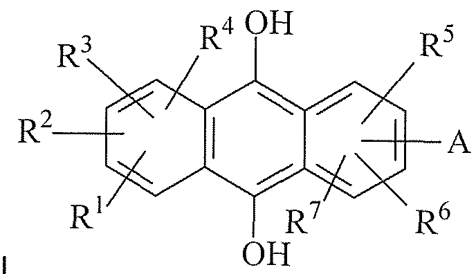
- a rechargeable battery comprising a first electrode and a second electrode separated by an ion-conducting barrier, wherein in its charged state, said rechargeable battery includes a molten salt comprising quinone or quinone derivative A having the structure of Formula I at the first electrode and a molten salt comprising hydroquinone or hydroquinone derivative B having the structure of Formula II or the structure of Formula III at the second electrode:
- the rechargeable battery includes the molten salt comprising quinone or quinone derivative A at the first electrode, said first electrode acting as a cathode, and the molten salt comprising
- the rechargeable battery includes the molten salt comprising the reduced quinone or quinone derivative A (i.e., the hydroquinone derivatives thereof) at the first electrode, said first electrode acting as an anode, and the molten salt comprising the oxidised hydroquinone or hydroquinone derivative B (i.e., the quinone derivatives thereof) at the second electrode, said second electrode acting as a cathode.
- the rechargeable battery In the charged state, the rechargeable battery includes the molten salt comprising quinone or quinone derivative A in its oxidised form, i.e.
- the rechargeable battery includes a molten salt comprising quinone or quinone derivative A in its reduced form, i.e. having the structure of Formula IB:
- the rechargeable battery includes the molten salt comprising hydroquinone or hydroquinone derivative B in its oxidised form, i.e. having the structure of Formula lib or Formula lllb:
- the battery of the present invention may be recharged by causing charge to flow in the opposite direction through the oxidation of the reduced form of quinone or quinone derivative A according to reaction scheme 1 b, and the reduction of the oxidised form of hydroquinone or hydroquinone derivative B according to reaction scheme 2b or reaction scheme 3b.
- batteries comprising ionic liquid electrolytes are known, such ionic liquids do not participate in the electron transfer reactions of known batteries.
- the molten salts of the batteries of the present invention participate in the electron transfer reactions.
- the battery of the present invention is charged and discharged through the oxidation and reduction of the quinones and quinone derivatives of the molten salts.
- the reactants of the redox reactions of the battery of the present invention are in liquid form and this provides important advantages over known batteries. In particular, the risks of fire or explosion are minimised.
- the molten salt may be a liquid condensed phase material.
- the molten salt is a liquid condensed phase quinone or quinone derivative, or hydroquinone or hydroquinone derivative.
- the first and/or second electrode comprises a platinum electrode.
- the platinum electrode comprises a platinum mesh.
- the first and/or second electrode may comprise a material selected from the list comprising platinum, gold, platinium coated titanium, gold coated titanium and glassy carbon foam.
- the ion-conducting barrier is formed from solid polymer electrolyte (SPE).
- SPE may be Nafion®, in particular National® 1 17.
- the ion-conducting barrier is formed from a perfluorinated polymer possessing fixed sulfonate groups. Typically, the perfluorinated polymer possessing fixed sulfonate groups is protonated.
- quinone or quinone derivative B has the structure of Formula III.
- hydroquinone or hydroquinone derivative B may have the structure of a four or five ring hydroquinone system.
- the molten salt comprises the quinone or quinone derivative, or the hydroquinone or hydroquinone derivative B, and an anionic or cationic counter-ion. Where the quinone or quinone derivative is cationic, the counter-ion is anionic and vice versa.
- the molten salt consists of cations and anions only.
- the molten salt may consist essentially, or alternatively exclusively, of the quinone or quinone derivative, or the hydroquinone or hydroquinone derivative, and an anionic or cationic counter-ion.
- the molten salt further comprises a further ionic liquid which does not comprise a quinone or hydroquinone or derivatives thereof.
- the further ionic liquid may comprise the same counter ion as the quinone or hydroquinone or derivative thereof.
- the further ionic liquid may comprise bis(trifluoromethyl-sulphonyl) imide as an anion.
- the molten salts comprising quinone or quinone derivative A, or hydroquinone or hydroquinone derivative B are in liquid form, suitably in the form of an ionic liquid, typically having a melting point of 100 ° C or less, generally in the form of an ionic liquid having a melting point of 50 ° C or less, preferably in the form of an ionic liquid having a melting point of below 25 °C.
- the molten salts of the battery of the present invention are in a pure, condensed phase, and are not diluted in any solvent. Thus, the molten salts may be undiluted.
- the concentration of redox sites at the first and second electrodes of the battery of the present invention is typically at least 5 to 10 times higher than known redox flow- through batteries, in particular known rechargeable batteries where the anionic and cationic species are generally dissolved in a solvent.
- This increase in the number of redox sites at the electrodes of the present invention leads to a corresponding increase in redox reactions, and a corresponding intensification in electrical energy storage capacity relative to batteries comprising redox reagents dissolved in solvents.
- the quinone or quinone derivatives, or the hydroquinone or hydroquinone derivatives, of the battery of the present invention may be dissolved in one or more solvents.
- suitable solvents include water, ionic liquids, glycols, alkylene carbonates such as propylenecarbonate, polyethers such as dimethoxyethane, CO2 and supercritical CO2.
- the difference in redox potential ( ⁇ ) between the redox reactions of quinone or quinone derivative A and hydroquinone or hydroquinone derivative B is at least 0.0V; typically at least 1 .0V; advantageously at least 1 .5V.
- the redox potential (EO) of quinone or quinone derivative A may be 0.5V or more, typically 0.6V or more.
- the redox potential (E0) of hydroquinone or hydroquinone derivative B may be -0.5V or less, typically -0.6V or less, suitably -1 .0V or less, advantageously -1.2V or less.
- the number of electrons involved in the redox reactions of quinone or quinone derivative A and hydroquinone or hydroquinone derivative B determines the current of the battery.
- the power of the battery is also related to the number of electrons involved in the redox reactions, where power is the product of the current and the difference in redox potential ( ⁇ ) between the redox reactions of quinone or quinone derivative A and hydroquinone or hydroquinone derivative B.
- ⁇ difference in redox potential
- hydroquinone or hydroquinone derivative B according to reaction scheme 2a or reaction scheme 3a.
- the current of the battery of the present invention is as high as, or higher than, most known redox flow-through batteries, in particular most known rechargeable batteries.
- the current density of the battery of the present invention is 0.5 Amp/cm 2 of electrode area or more.
- the battery of the present invention can support heavy current devices, and can maintain a high current for relatively long periods of time.
- the voltage generated by the battery of the present invention is as high as, or higher than, most known redox flow-through batteries, in particular most known rechargeable batteries.
- the battery of the present invention can be recharged reliably with relatively limited energy input relative to recharging processes for known rechargeable batteries.
- the battery of the present invention can reliably be recharged numerous times.
- the recharging process typically results in the battery becoming fully recharged, or recharged up to at least 90% of its initial redox potential, suitably at least 95% of its initial redox potential, advantageously up to approximately 100% of its initial redox potential. Accordingly, the battery of the present invention has a long and predictable shelf-life relative to known rechargeable redox flow-through batteries.
- the battery of the present invention is charge balanced.
- the battery of the present invention is typically an enclosed system, nothing is added and nothing is taken away through the redox reactions which take place therein. Accordingly, the battery of the present invention is also mass balanced.
- the battery of the present invention may be scaled up easily and efficiently.
- Energy storage capacity is a function of volume and thus increasing the volume of quinone or quinone derivative A and
- hydroquinone or hydroquinone derivative B used increases the energy storage capacity of the battery of the present invention.
- the volume of quinone or quinone derivative A should be increased by the same molar proportion as the increase in hydroquinone or hydroquinone derivative B for the energy storage capacity to be scaled up accordingly.
- the energy storage capacity of the battery of the present invention is at least 0.01 Amp hour per cm 3 of liquid, suitably at least 0.1 Amp hour per cm 3 of liquid, advantageously 1 Amp hour per cm 3 of liquid.
- the ion-conducting barrier of the present invention physically separates quinone or quinone derivative A from hydroquinone or hydroquinone derivative B whilst allowing ions to flow therethrough.
- the ion-conducting barrier allows positively charged ions such as H + to flow therethrough.
- Any known ion-conducting barrier may be used.
- the ion-conducting barrier is formed from solid polymer electrolyte (SPE), such as that sold under the trade mark National® (in particular Nafion® 1 17) which is a perfluorinated polymer possessing fixed sulfonate groups.
- SPE solid polymer electrolyte
- the perfluorinated polymer possessing fixed sulfonate groups can be protonated by boiling in acid to obtain a very effective membrane.
- the anode and/or cathode may be formed from any material known for such applications.
- the anode and/or cathode are formed from carbon.
- the anode and/or cathode may be formed from carbon having an electrocatalyst dispersed thereon, wherein the electrocatalyst is typically a precious metal or alloy such as Pt, Pt/Ru or Au.
- the electrocatalyst may also be directly dispersed onto the ion- conducting barrier.
- quinone or quinone derivative A has the structure as shown below:
- hydroquinone or hydroquinone derivative B has the structure as shown below:
- hydroquinone or hydroquinone derivative B has the structure as shown below:
- R1 to R7 may independently be A; hydrogen; C1 to C10 linear, branched chain or cyclic alkyl groups; aryl; heterocycles; CI, Br, I, CN; OH or O2 wherein said alkyl and aryl substituents may themselves be substituted or unsubstituted;
- A may represent an anion hetero-atom species. If the quinone or quinone derivative is cationic, or the
- hydroquinone or hydroquinone derivative is cationic, A may represent a cationic hetero-atom species;
- A typically represents SO 3" , COO “ , O- HPO3 " , O-PO3 2" or R-O-SO3 " and
- R1 - R7 may independently represent imidazolium, piperidinium, pyridinium, phosphonium, pyrazinium, quaternary amine, ammonium species or derivatives thereof; or one or more of the ring atoms may be a quaternised heteroatom and each quaternised heteroatom may
- A represents hydrogen, a CI to C10 linear, branched chain or cyclic alkyl group; an aryl group; a heterocycle group; CI, Br, I, CN; OH or NO 2 wherein said alkyl and aryl substituents may themselves be substituted or unsubstituted.
- a and optionally one or more of R1 to R3 may independently represent imidazolium, piperidinium, pyridinium, phosphonium, pyrazinium, quaternary amine, ammonium species or derivatives thereof;
- ring atoms may be a quaternised heteroatom and A may represent hydrogen; a CI to C10 linear, branched chain or cyclic alkyl group; an aryl group; a heterocycle group; CI, Br, I, CN; OH or NO2 wherein said alkyl and aryl substituents may themselves be substituted or unsubstituted.
- any ring atom of any one of the Formulae may be a heteroatom, such as N, S, O or P, that may suitably be quaternised to form a cationic species.
- Formulae may be anywhere on any of the rings.
- aryl includes for example phenyl, polyphenyl, benzyl and similar moieties.
- quinone derivative includes quinone derivatives, naphthoquinone and derivatives thereof, anthroquinone and derivatives thereof and, unless the context dictates otherwise, the hydroquinone derivatives of the aforementioned compounds.
- the A group of the quinone or quinone derivative A, or the hydroquinone or hydroquinone derivative B is S0 3 " , COO “ , O-HPO 3 " , O-PO3 2 or R-O-SO3 " .
- the quinone or quinone derivative B has the structure as shown below:
- hydroquinone and hydroquinone derivative B will, or course, have a corresponding hydroquinone-type structure.
- the cation (Ca ) of the molten salt is suitably an aliphatic or aromatic hydrocarbon species typically possessing a hetero-atom, such as N, S, P and O.
- the aliphatic or aromatic hydrocarbon species typically possessing a hetero-atom, such as N, S, P and O.
- hydrocarbon species may be substituted or unsubstituted, typically with one or more of any substituted or unsubstituted alkane, alkene, alkyne or aromatic hydrocarbon or any halogen group such as a fluorocarbon group.
- the cation may comprise one or more amine, amide, nitrile, halogen, ether, alcohol, thiol, acid, ester, aldehyde, ketone or phosphine group.
- the cation comprises a branched alkyl chain such as a fluorinated branched alkyl chain. In one embodiment the cation is
- the cation may be selected from the group consisting of imidazolium, piperidinium, pyridinium, phosphonium, pyrrolidinium, pyrazinium, quaternary amine, ammonium species and derivatives thereof.
- the cation is selected from the group consisting of imidazolium, piperidinium, phosphonium quaternary amine and ammonium species.
- Cat + is an imidazolium cation it is preferably a cation of Formula IV:
- R Formula VII In one embodiment the cation is tetradecyltrihexylphosphonium and has the structure:
- R 1 to R 7 may independently be hydrogen, a substituted or unsubstituted C to C10 linear or branched alkyl chain, a substituted or unsubstituted cyclic alkyl group, an aryl group, CN, OH, NO 2 , SO 3 or COO " .
- Cat + is a quaternary amine it is preferably of the form NR 4 + where each R group is independently a substituted or unsubstituted C1 to C20 linear or branched alkyl chain or a substituted or unsubstituted cyclic alkyl group.
- the alkyl groups may be substituted with one or more alkane, alkyne or aromatic hydrocarbon or any halogen group such as a fluorocarbon group.
- the cation is tetraalkylammonium or tetraalkylphosphonium.
- the anion of the molten salt is suitable anionic species such as PF 6 , tetrafluoroborate, bistriflimide, triflate, fluoroalkylsulfonates , nitrate, a phosphate such as
- the anion is dicyanamide or bistriflimide.
- the redox reactions of the battery of the present invention generally proceed at temperatures of 100 °C or less; typically 25 ° C or less.
- the redox reactions of the battery of the present invention proceed at temperatures of between 10 and 100 °C. Typically oxygen is excluded from the battery of the present invention. Generally the redox reactions proceed within a closed system, suitably under an inert atmosphere such as N 2 , if necessary.
- the quinones or quinone derivatives of the battery of the present invention are generally non-volatile under the normal operating conditions of the battery.
- the quinones or quinone derivatives, or the hydroquinone or hydroquinone derivatives, of the present invention are generally in liquid form; either in pure liquid form or dissolved in a solvent.
- the battery of the present invention is mass and charge balanced and generally operates as a closed system. As such, the battery of the present invention does not dry out under normal operating conditions.
- the battery of the present invention poses a very low fire, explosion or toxicity risk compared to known batteries, in particular compared to known batteries having a similar energy storage capacity.
- the battery of the present invention does not generally include any metal compounds.
- the battery of the present invention does not generally include any molten metals.
- the battery of the present invention does not generally comprise any corrosive electrolytes.
- the battery of the present invention is comparatively environmentally benign.
- the battery of the present invention can be disposed of easily without risk of toxic emissions therefrom, and this provides an important advantage over known batteries.
- the battery of the present invention may be in any known form, including hand held batteries to charge, for instance toys or music equipment; fuel cells for the storage of energy generated through solar, wave,
- the battery of the present invention is in the form of a very large volume energy storage cell, where the battery of the present invention has an energy storage capacity proportional to stored liquid volume.
- the battery of the present invention is in the form of an energy storage cell having an energy storage capacity up to GW depending on stored volume of liquids for the storage of wind, wave, hydroelectric or solar energy.
- the battery of the present invention can be formed in known, standard types of redox flow battery apparatus.
- quinone or quinone derivatives A and the hydroquinone or hydroquinone derivatives B may be provided in known membrane electrode assemblies (MEA) as shown in Figure 1 .
- MEA membrane electrode assemblies
- Such ME A have a proven reliability established following long and extensive use in energy delivery (fuel cells) and storage (flow-through redox batteries) applications.
- the MEA is formed from a solid polymer electrolyte, such as that sold under the trade mark National®.
- the ion- conducting barrier typically physically separates a first chamber housing the quinone or quinone derivative A from a second chamber housing the hydroquinone or hydroquinone derivative B.
- the chambers are typically formed from a conducting material such as metal or a conducting plastic, or an insulating material. Where the chambers are constructed form a conducting material, these may directly contact the anode/cathode bonded to the MEA, around its periphery, to provide simple electric connection (suitably through the current collectors as shown in Figure 1). Where the chambers are constructed form a non-conducting material, contacts with the anode/cathode may be made with a metallic component or
- redox-active liquids may be "stored" in reservoirs from which they will be pumped to their respective electrodes for charging and discharging. Obviously, since the electrode reactions are mass/charge balance, this will be an entirely closed system.
- Figure 1 comprises; 2: stainless steel body
- a quinone or quinone derivative A having the structure of Formula I, and hydroquinone or hydroquinone derivative B having the structure of Formula II or the structure of Formula III (as shown above) in energy storage applications, wherein energy is stored through the flow of charge from a first electrode to a second electrode through the oxidation of the reduced form of quinone or quinone derivative A according to the reaction shown in scheme 1 b (as shown above) and the reduction of the oxidised form of hydroquinone or hydroquinone derivative B according to reaction scheme 2b or 3b (as shown above).
- Energy is spontaneously released through allowing the flow of charge in the reverse direction, i.e. through the spontaneous oxidation of hydroquinone or hydroquinone derivative B according to reaction scheme 2a or 3a (as shown above) and the contemporaneous reduction of quinone or quinone derivative A according to reaction scheme 1 a (as shown above).
- a method of producing a rechargeable battery comprising the steps of: providing a first electrode and a second electrode, separated by an ion- conducting barrier;
- quinone or quinone derivative A having the structure of Formula 1 (as shown above) at the cathode in the charged state and quinone or quinone derivative B having the structure of Formula II (as shown above) or the structure of Formula III (as shown above) at the anode in the charged state:
- the rechargeable battery is as described above.
- Figure 1 shows a known MEA battery arrangement
- Figure 2 shows a cyclic voltammogram of the compound of Example 1 ;
- Figure 3 shows a cyclic voltammogram of the compound of Example 2;
- Figure 4 shows a cyclic voltammogram of the compound of Example 3;
- Figure 5 shows a cyclic voltammogram of the compound of Example 4;
- Figure 6 shows a cyclic voltammogram of 0.01 M [BMIM][HQS] in 0.1 M TBATFB/ACN using a carbon macro working electrode, Ag/AgCI reference and Pt wire auxiliary;
- Figures 7a to 7c show plots of the square root of the sweep rate ( ⁇ 1/2 ) versus cathodic current (i pc ) for 0.01 M [B IM][HQS] in 0.1 M TBATFB/ACN using different working electrodes;
- Figure 8 shows a cyclic voltammogram of 0.01 M [BMIM][HQS] in pure [BMIM][NTF 2 ] using a carbon macro electrode, Ag/AgCI reference and Pt wire auxiliary at different sweep rates;
- Figures 9a to 9c show plots of the square root of the sweep rate ( ⁇ /2 ) versus cathodic current (i pc ) for 0.01 M [BMIM][HQS] in pure [BMIM][NTF 2 ] using different working electrodes;
- Figure 10 shows cyclic voltammetry of pure [BMIM][HQS] using a carbon macro working electrode, Ag/AgCI reference and Pt wire auxiliary;
- Figure 1 1 shows cyclic voltammetry of pure [BMIM][HQS] using a gold micro working electrode (diameter 100 ⁇ ), Ag/AgCI reference and Pt wire auxiliary;
- Figures 12a to 12c show plots of ⁇ 1 2 versus i pc of pure [BMIM][HQS] using the different working electrodes for a carbon macro working electrode, a platinum macro working electrode and a gold macro working electrode, respectively;
- Figure 13 shows cyclic voltammograms of 0.01 M [P14666][HQS] in 0.1 M TBATFB ACN using a carbon macro electrode at different sweep rates;
- Figures 14a to 14c show plots of the square root of the sweep rate ( ⁇ ) versus cathodic current (i pc ) for 0.01 M [P14666][HQS] in 0.1 M TBATFB ACN using different working electrodes;
- Figure 15 shows a cyclic voltammogram of 0.01 [P14666][HQS] in pure [P14666][NTF2] using a carbon macro working electrode, Ag/AgCI reference and Pt wire auxiliary;
- Figures 16a to 16c show plots of ⁇ 1/2 versus i pc of pure 0.01 M
- Figure 17 shows cyclic voltammograms of 0.01 M [P14666][NQS] in 0.1 M TBATFB ACN using a carbon macro electrode at different sweep rates;
- Figures 18a and 18b show a plot of ⁇ 1/2 vs. i pc for 0.01 M [P14666][NQS] in 0.1 M TBATFB ACN using a carbon macro working electrode and a gold macro working electrode, respectively;
- Figure 19 shows the cyclic voltammograms of 0.01 M [P14666][AQS] in 0.1 M TBATFB ACN using a carbon macro electrode at different sweep rates;
- Figures 20a to 20c show plots of ⁇ 1/2 vs. i pc for 0.01 M [P14666][AQS] in 0.1 M TBATFB ACN using a carbon macro working electrode, a platinum macro working electrode and a gold macro working electrode respectively;
- Figure 21 shows the cyclic voltammogram of 0.01 M [P14666][AQS] in pure [P14666][NTF 2 ] using a carbon working electrode, Ag/AgCI reference and Pt wire auxiliary electrode;
- Figures 22a to 22c show plots of ⁇ 1 /2 vs. i pc for 0.01 M [P14666][AQS] pure [P14666][NTF 2 ] using a carbon macro working electrode, a platinum working electrode and a gold working electrode respectively;
- Figure 23 shows cyclic voltammograms of 0.01 M [C14H30N][HQS] in 0.1 M TBATFB using a carbon macro working electrode, Ag/AgCI reference and a Pt wire auxiliary electrode;
- Figures 24a to 24c show plots of ⁇ 1 " vs. i pc for for 0.01 M [C14H30N][HQS] in 0.1 M TBATFB ACN using a carbon macro working electrode, a platinum working electrode and a gold working electrode respectively;
- Figure 25 shows cyclic voltammograms of 0.01 M [C14H30N][HQS] in pure [C14H30N][NTF 2 ] using a carbon macro working electrode;
- Figures 26a to 26c show plots of ⁇ 1/2 vs. i pc for 0.01 M [C14H30N][HQS] in pure [C14H30N][NTF 2 ] using a carbon macro working electrode, a platinum working electrode and a gold working electrode respectively;
- Figure 27 shows cyclic voltammograms of 0.01 M [C14H30N][AQS] in 0.1 M TBATFB ACN using a carbon macro working electrode;
- Figures 28a to 28c show plots of ⁇ 1 2 vs. i pc for 0.01 M [C14H30N][AQS] in 0.1 M TBATFB ACN using a carbon macro working electrode, a platinum working electrode and a gold working electrode respectively;
- Figure 29 shows cyclic voltammograms of 0.01 M [C14H30N][AQS] in pure [C14H30N][NTF 2 ] using a carbon macro working electrode;
- Figure 30 shows a plot of ⁇ 1/2 vs. i pc 0.01 M [C14H30N][AQS] in pure
- Figure 31 shows a cell set-up used to study the pairs of ionic liquids in accordance with the present invention
- Figure 32 shows a cyclic voltammogram of a [P14666][HQS] /
- Figure 33 shows the Nyquist plot of a [P14666][HQS] / [P14666][AQS] redox couple
- Figure 34 shows the change in open circuit potential with time after a current of 100mA has been applied to the HQS side of a battery cell
- Figure 35 shows the change in the open circuit potential before and after the application of 100 ⁇ for 4 hours.
- Figure 36 shows the change in the open circuit potential before and after the application of -100 ⁇ for 5 hours.
- the voltammetry displayed in Figures 2 to 5 is indicative of a reversible 2- electron 2-proton reduction process (i.e. negative current) occurring on the negative voltage sweep, leading to the corresponding anthrahydroquinone species, which is reoxidised via a 2-electron 2-proton oxidation process (positive current) on the positive voltage sweep.
- a reversible 2- electron 2-proton reduction process i.e. negative current
- anthrahydroquinone species which is reoxidised via a 2-electron 2-proton oxidation process (positive current) on the positive voltage sweep.
- the following quinone-based ionic liquid was prepared and the storage capacity of a battery comprising this ionic liquid was investigated as detailed above.
- the following quinone-based ionic liquid was prepared and the storage capacity of a battery comprising this ionic liquid was investigated as detailed above.
- the following quinone-based ionic liquid was prepared and the storage capacity of a battery comprising this ionic liquid was investigated as detailed above.
- the following quinone-based ionic liquid was prepared and the storage capacity of a battery comprising this ionic liquid was investigated as detailed above.
- NTF2 bis(trifluoromethyl-sulphonyl) imide
- C14H30N 1-methyl-octyl-pyridinium
- [HQS] hydroquinone sulfonate
- [AQS] 1 ,4-anthraquinone sulfonate.
- the electrochemical analysis was performed using a standard three electrode cell under an inert nitrogen atmosphere (which was degassed prior to use).
- a silver/silver chloride (Ag/AgCI) reference electrode and platinum wire auxiliary electrode were used.
- a Voltalab PGZ301 potentiostat and a Sycopel AEW2 potentiostat (with attached Faraday cage) were used to record the voltammetry performed in this study. Cyclic voltammetry was used to analysis the oxidation/reduction of the quinones involved. For hydroquinone liquids the potential was swept from 0 to 1300 to - 800mV. For naphthaquinone and anthraquinone based liquids the potential was swept from 0 to -1800 mV. Three cycles were recorded. Ohmic compensation was applied to all voltammetry recorded using the Voltalab potentiostat but not to the voltammetry obtained using the Sycopel potentiostat. Example 5 - ⁇
- Figure 6 shows a summary of the CVs for this solution at different sweep rates using a carbon macro electrode.
- Tables 2 to 5 show a summary of the electrochemical data obtained including the values for the oxidation potential (E pc ) and the reduction potential (E pa ), cathodic and anodic currents (i pc and i pa ), the change in potential ( ⁇ ⁇ ) and ratio of cathodic to anodic current (i pc /i P a). It should be noted that all currents have been baseline corrected and corrected for area.
- Figures 7a-7c show plots of the square root of the sweep rate ( ⁇ 1/2 ) versus cathodic current (i pc ) using the different working electrodes.
- ⁇ ⁇ can be attributed to the fact that the reduction peak occurs at a less positive potential when a gold working electrode is used (E pa ranges from 0.218V at slower sweep rates to 0.094V at faster sweep rates for gold, whilst for carbon it ranges from 0.485V to 0.379V and 0.378V to 0.350V for platinum).
- E pa ranges from 0.218V at slower sweep rates to 0.094V at faster sweep rates for gold
- carbon ranges from 0.485V to 0.379V and 0.378V to 0.350V for platinum.
- the size of the current i P a and i pc
- Figures 7a - 7c show the plots of ⁇ 1/2 vs. i pc are not purely linear and as expected for quasi-reversible behaviour there are some deviations from linearity, particularly at slower sweep rates. These plots have been used to calculate the diffusion coefficients (Table 6) for the macro working electrodes using Randles-Sevcik equation 3 which can be simplified at 298K to Equation 1 .
- i p ⁇ 2.69xlO*)n2AC 0 Di&2 (Eqn. 1)
- i p the current (A)
- n the number of electrons
- A the electrode area (cm 2 )
- C 0 the concentration (molcnrf 3 )
- D 0 the diffusion coefficient (cm 2 s “1 )
- ⁇ the sweep rate (V s "1 ).
- Equation 3 a different equation (Equation 3) must be used to calculate the diffusion coefficient for a micro electrode system.
- i d is the current
- n is the number of electrons
- F is the current
- [BMIM][NTF 2 ] also exhibits a quasi-reversible oxidation/reduction profile.
- the size of the current for the oxidation of the hydroquinone is significantly larger than that for the corresponding reduction, which as mentioned previously is due to the difference in kinetics of the two processes 2 .
- the reduction peak completely disappears as previously observed in the acetonitrile solution.
- Table 1 1 As Figure 8 shows 0.01 M [BMIM][HQS] in pure [BMIM][NTF 2 ] exhibits a similar oxidation/reduction pattern to that which was previously observed in 0.1 M TBATFB ACN ( Figure 6) i.e. a large oxidation peak coupled with a smaller reduction peak (there are additional peaks in the NTF 2 system which may be due to impurities in the system e.g. oxygen). The oxidation and reduction potentials are slightly less positive than those observed previously in 0.1 M TBATFB ACN.
- the oxidation potential of 0.01 M [BMIM][HQS] in pure [BMIM][NTF 2 ] using a carbon macro working electrode at 0.05 Vs "1 was 0.831 V whilst the oxidation potential for the same concentration of [BMIM][HQS] in 0.1 M TBAFTB ACN using the same carbon macro electrode at the same sweep rate was 1 .044V (the corresponding reduction potentials were 0.365V and 0.464V respectively resulting in ⁇ ⁇ values of 0.466V and 0.580V).
- Figure 10 shows cyclic voltammetry of pure [BMIM][HQS] using a carbon macro working electrode, Ag/AgCI reference and Pt wire auxiliary. The voltammetry at a number of different sweep rates is shown.
- Figure 1 1 shows cyclic voltammetry of pure [BMIM][HQS] using a gold micro working electrode (diameter 100 ⁇ ), Ag/AgCI reference and Pt wire auxiliary. The voltammetry at a number of different sweep rates is shown.
- Tables 12 - 15 show a summary of CV data obtained using different working electrodes for pure [BMIM][HQS]. All the potentials are quoted against an Ag/AgCI reference electrode.
- Figures 12a - 12c show plots of ⁇ 1 2 versus ipc using the different working electrodes for a carbon macro working electrode, a platinum macro working electrode and a gold macro working electrode, respectively.
- Figure 13 shows the cyclic voltammetry of this solution obtained using a carbon macro working electrode, Ag/AgCI reference electrode and Pt wire auxiliary electrode. The voltammetry at a number of sweep rates is shown.
- Tables 16 - 19 show a summary of the key electrochemical data obtained from the analysis of 0.01 M [P14666][HQS] in 0.1 M TBATFB ACN using different working electrodes.
- Figure 17 shows the CV of 0.01 M [P14666][NQS] in 0.1 M TBATFB ACN obtained using a carbon macro working electrode, Ag/AgCI reference and Pt wire auxiliary.
- the relevant electrochemical data for this electrode and the others tested is summarised in Tables 25 - 26.
- [P14666][NQS] in 0.1 M TBATFB ACN exhibits voltammetry which is typical for a naphthaquinone derivative. Both reduction and re-oxidation occur at negative potentials and are reversible.
- Table 27 A summary of the diffusion coefficients obtained (from Figures 18a and 18b) using the different working electrodes tested are shown in Table 27. The data for the platinum macro electrode is not shown as the voltammetry obtained was unusual and was most probably caused by an artefact on the electrode surface.
- FIG. 19 An example of some CVs obtained at different sweep rates using a solution of 0.01 M [P14666][AQS] in 0.1 M TBATFB are shown in Figure 19.
- the working electrode used was a carbon macro electrode, the reference electrode Ag/AgCI and the auxiliary electrode Pt wire.
- Tables 28 - 30 show a summary of the key electrochemical derived from the CV of this solution using a number of different working electrodes.
- [P14666][AQS] in 0.1 M TBATFB ACN exhibits a reversible two- step, two- electron reduction/oxidation profile which occurs at negative potentials.
- the diffusion coefficients for the systems have been calculated from plots of ⁇ 1/2 vs. ip C ( Figures 20a - 20c) and are summarised in Table 31.
- [P14666][NTF2] is shown in Figure 21.
- the working electrode used was a carbon macro electrode; Ag/AgCI reference and Pt wire auxiliary electrode were also used.
- Tables 32 - 34 show a summary of the key
- [P14666][NTF 2 ] is the same as that which has previously been observed in 0.1 M TBATFB ACN. Unlike the naphthaquinone equivalent which displayed irreproducible voltammetry the anthraquinone derivative appears to display more reproducible voltammetry, however, it should be noted that there are some inconsistencies which became evident over time and as the working electrode is varied. Investigations into these effects are continuing at present.
- the diffusion coefficients for 0.01 M [P14666][AQS] in pure [P14666][NTF 2 ] obtained from Figures 22a - 22c are shown in Table 35.
- this solution exhibits untypical electrochemistry for the oxidation and re-reduction of a hydroquinone species.
- the exact cause of this effect is not known however, it is thought to be due to one of two effects - either the presence of chloride or a form a self electro-catalysis which has previously been identified in hydroquinone's in aqueous un-buffered media (Chaudhari et al.) 5 .
- the effect is essentially caused by the development of a surface confined quinone layer at the electrode surface which results in the hydroquinone getting oxidised at two different catalytic centres.
- FIG. 31 A prototype cell which allowed the testing of the chosen redox active ionic liquid couple was designed and built.
- the cell body was constructed from brass.
- This cell was basically a compact version of an H shaped cell which is conventionally used to study transport through membranes. It consisted of two chambers which were separated by a protonated membrane (the membrane is used to facilitate proton transfer and to ensure the two components remain separated). Each chamber was filled with one of the redox active ionic liquids and the cell connected through simple screws to a potentiostat. This is shown in Figure 31 , which comprises:
- the cell described in Figure 31 was constructed using a PTFE body instead of a brass body - this was done to eliminate the adverse chemical reactions which were observed using brass and to try and improve the performance of the cell.
- the electrode arrangement within the cell was also altered, i.e. a platinum mesh electrode was added into each cell half.
- the platinum was placed in a number of positions within the cell including in direct contact with the membrane but this arrangement was not found to be suitable, i.e. there was no change to the open circuit potential when different currents were applied to the cell. Instead, the platinum mesh was carefully folded to create small 'cups' which were placed in the cavities within the PTFE cell in direct contact with the ionic liquids.
- a small piece of platinum/iridium wire was threaded through each mesh to the exterior of cell and the wire was connected to the potentiostat.
- the results from the impedance spectroscopy of the cell were mixed - but generally displayed a semi-circle in the high frequency region of the plot.
- the lower frequency region was typically very noisy but there was no obvious Warburg behaviour.
- An example of the plot obtained is shown in Figure 33.
- the impedance spectrum was recorded using the HQS side of the cell as the working electrode and the AQS side of the cell as the counter electrode.
- the reference was clipped to the counter electrode.
- the spectrum was recorded from 100 kHz to 200 Hz.
- the applied potential was 1000mV.
- Tables 51 b and 52b show the change to the OCP following each impedance spectrum. As Tables 51 b and 52b show the open circuit potential only changes by a small amount after the impedance has been run and decays very quickly again back to near its original value.
- a potentiostat was used to apply small currents to the cell and to measure the change which occurred to the open circuit potential of the cell as a result.
- the results of the trials performed are shown below (Example 13 and Example 14). It is important to note that as expected once the cell had been subjected to a change it never regained its initial open circuit potential. In addition to this once a current has been applied the OCP
- Example 13 Working electrode pure fP146661fHQS], auxiliary and reference pure fP14666irAQSl. PTFE cell.
- Open circuit potential recorded after charging (recorded over 120 minutes): 1382 - 1278 mV
- Figure 35 shows the change in the open circuit potential before and after the application of 100 ⁇ for 4 hours.
- Table 53 shows the calculation of charge passed and mass of material converted during charging for
- Figure 36 shows the change in the open circuit potential before and after the application of -100 ⁇ for 5 hours.
- Table 54 shows the calculation of charge passed and mass of material converted during charging for
- a glass version of the cell described above was also prepared. It should be noted that although the cell body has changed the working principles of the cell remain the same, i.e. the membrane type and electrodes used were the same. The key advantages of using a cell of this type are that filling the cell is much simpler and a visual check can be kept on the cell components. The same types of trials as those performed previously using the PTFE cell were performed. A sample of the results for the oxidation of hydroquinone side of the cell are summarised below. As a comparison of these results with the results shown previously for the PTFE cell indicate as expected the two cells act in the same way.
Landscapes
- Life Sciences & Earth Sciences (AREA)
- Engineering & Computer Science (AREA)
- Manufacturing & Machinery (AREA)
- Sustainable Development (AREA)
- Sustainable Energy (AREA)
- Chemical & Material Sciences (AREA)
- Chemical Kinetics & Catalysis (AREA)
- Electrochemistry (AREA)
- General Chemical & Material Sciences (AREA)
- Battery Electrode And Active Subsutance (AREA)
Abstract
A rechargeable battery comprising a first electrode and a second electrode separated by an ion-conducting barrier, wherein in its charged state, said rechargeable battery includes a molten salt comprising quinone or quinone derivative A having the structure of Formula (I) as described at the first electrode and a molten salt comprising hydroquinone or hydroquinone derivative B having the structure of Formula (II) or Formula (III) as described at the second electrode, wherein during the discharging process, charge flows from the second electrode to the first electrode through the reduction of quinone or quinone derivative A according to reaction scheme 1a as described, and the oxidation of hydroquinone or hydroquinone derivative B according to reaction scheme 2a or reaction scheme 3a as described.
Description
REDOX BATTERY
The present invention relates to the use of quinones in the form of molten salts (ionic liquids) in energy storage applications. There is also provided a rechargeable electric battery comprising ionic liquid quinones and a method for producing such.
Redox batteries work by spontaneously, and simultaneously, performing an oxidation reaction (i.e., loss of electrons (e")) at one electrode and a reduction reaction (i.e., gain of electrons) at another electrode where the electrons lost/gained flow through a circuit from one electrode to the other. For example, species A is spontaneously oxidised to species B at an anode while species C is spontaneously reduced to species D at the cathode.
Anode : A = B + e- (E1 )
Cathode : C + e" = D (E2) The overall chemical reaction is therefore;
Overall : A + C = B + D (ΔΕ = I E2 | + | E1 I)
For the overall reaction to happen spontaneously, the redox potential difference (AV) between the anode (El ) and cathode (E2) reactions must be > 0.0 V. This is because the Gibbs free energy (ΔΘ) of reaction must be negative for a spontaneous reaction to occur i.e. AG = -nFAE, where n is the number of electrons per molecule and F is the Faraday constant. Since the overall reaction is spontaneous, it will also happen
spontaneously (without current flow) if A and C are mixed in the same
solution. The battery's "trick" is to separate A and C into compartments where the anode and cathode are electronically connected in a circuit (for electron flow) and ionically connected with some type of ion-conducting membrane (e.g. a solid polymer electrolyte (SPE)) which allows positively charged ions (usually H+) to flow from the anode chamber to the cathode chamber to maintain electroneutrality. If the oxidation and reduction reaction are reversible, the battery can be recharged for reuse.
Non-rechargeable batteries are known and commonly used. Zinc-carbon batteries have been known for many years. However, these batteries are associated with significant problems, in particular with regard to short and unpredictable shelf-life. Batteries comprising zinc powder as the anode, and manganese dioxide as the cathode are also well known. Such, alkaline batteries have a high energy density and a long shelf life compared to zinc-carbon batteries. Their capacity is strongly dependent on the load applied as the faster an alkaline battery is drained, the greater the percentage of its load is dissipated as heat. As such, alkaline batteries can be very inefficient. Alkaline batteries contain hazardous materials, in particular potassium hydroxide and Zn2+ and are difficult to dispose of.
Other forms of non-rechargeable battery are also commonly known, including lithium batteries. Lithium batteries comprise lithium, or a lithium compound as an anode. These batteries are reliable and have a long shelf life compared to other types of non-rechargeable battery. They can generate relatively high voltages, commonly up to 3V, and can support heavy current devices and maintain a high current for relatively long periods of time. However, lithium batteries are associated with rapid discharge of high currents which can lead to overheating. As such, lithium batteries can constitute an explosion risk. Furthermore, it is difficult to
dispose of lithium batteries due to their incorporation of hazardous materials such as lithium.
Several types of rechargeable battery are also commonly known, including lead/sulphuric acid batteries, nickel/cadmium batteries, nickel metal hydride batteries, lithium ion batteries and lithium ion polymer batteries. The energy storage capacity (Watts per m3) of known rechargeable batteries is generally also limited due to the difficulties of manufacturing these batteries on a very large scale. Also, known rechargeable batteries generally incorporate volatile materials and may constitute an overheating, fire or explosion risk. In addition such rechargeable batteries are associated with toxic emissions including emissions of Pb, Cd, Ni and hydroxide, and are difficult to dispose of.
Quinone compounds such as those shown below are known.


2006/003395 is hereby incorporated by reference. The use of such quinone compounds or derivatives in energy storage applications has not previously been contemplated.
According to a first aspect of the present invention there is provided a rechargeable battery comprising a first electrode and a second electrode separated by an ion-conducting barrier, wherein in its charged state, said rechargeable battery includes a molten salt comprising quinone or quinone derivative A having the structure of Formula I at the first electrode and a molten salt comprising hydroquinone or hydroquinone derivative B having the structure of Formula II or the structure of Formula III at the second electrode:

Formxi

Formula II
Formula III
wherein during discharge, charge spontaneously flows from the second electrode to the first electrode through the oxidation of hydroquinone or hydroquinone derivative B according to reaction scheme 2a or reaction scheme 3a, and the reduction of quinone or quinone derivative A according to reaction scheme 1 a:

Reaction Scheme 1 a

Reaction Scheme 3a
In the charged state, the rechargeable battery includes the molten salt comprising quinone or quinone derivative A at the first electrode, said first electrode acting as a cathode, and the molten salt comprising
hydroquinone or hydroquinone derivative B at the second electrode, said second electrode acting as an anode. In the uncharged state, the rechargeable battery includes the molten salt comprising the reduced quinone or quinone derivative A (i.e., the hydroquinone derivatives thereof) at the first electrode, said first electrode acting as an anode, and the molten salt comprising the oxidised hydroquinone or hydroquinone derivative B (i.e., the quinone derivatives thereof) at the second electrode, said second electrode acting as a cathode.
In the charged state, the rechargeable battery includes the molten salt comprising quinone or quinone derivative A in its oxidised form, i.e.
quinone or quinone derivative A having the structure of Formula I, and the molten salt comprising hydroquinone or hydroquinone derivative B in its reduced form, i.e. hydroquinone or hydroquinone derivative B having the structure of Formula II or the structure of Formula III. In the uncharged state, the rechargeable battery includes a molten salt comprising quinone or quinone derivative A in its reduced form, i.e. having the structure of Formula IB:


Formula IIB

The battery of the present invention may be recharged by causing charge to flow in the opposite direction through the oxidation of the reduced form of quinone or quinone derivative A according to reaction scheme 1 b, and the reduction of the oxidised form of hydroquinone or hydroquinone derivative B according to reaction scheme 2b or reaction scheme 3b.


Reaction Scheme 2b

Reaction Scheme 3b
Although batteries comprising ionic liquid electrolytes are known, such ionic liquids do not participate in the electron transfer reactions of known batteries. The molten salts of the batteries of the present invention participate in the electron transfer reactions. The battery of the present invention is charged and discharged through the oxidation and reduction of the quinones and quinone derivatives of the molten salts. The reactants of the redox reactions of the battery of the present invention are in liquid form and this provides important advantages over known batteries. In particular, the risks of fire or explosion are minimised.
The molten salt may be a liquid condensed phase material. For example in one embodiment the molten salt is a liquid condensed phase quinone or quinone derivative, or hydroquinone or hydroquinone derivative.
According to one aspect of the present invention, the first and/or second electrode comprises a platinum electrode. Advantageously, the platinum electrode comprises a platinum mesh. Alternatively the first and/or second electrode may comprise a material selected from the list comprising platinum, gold, platinium coated titanium, gold coated titanium and glassy carbon foam.
According to one aspect of the present invention, the ion-conducting barrier is formed from solid polymer electrolyte (SPE). The SPE may be Nafion®, in particular Nation® 1 17. Advantageously, the ion-conducting barrier is formed from a perfluorinated polymer possessing fixed sulfonate groups. Typically, the perfluorinated polymer possessing fixed sulfonate groups is protonated.
According to one aspect of the present invention quinone or quinone derivative B has the structure of Formula III.
Alternatively, hydroquinone or hydroquinone derivative B may have the structure of a four or five ring hydroquinone system.
Generally the molten salt comprises the quinone or quinone derivative, or the hydroquinone or hydroquinone derivative B, and an anionic or cationic counter-ion. Where the quinone or quinone derivative is cationic, the counter-ion is anionic and vice versa. Typically the molten salt consists of cations and anions only. For example, the molten salt may consist essentially, or alternatively exclusively, of the quinone or quinone derivative, or the hydroquinone or hydroquinone derivative, and an anionic or cationic counter-ion.
In an alternative embodiment, the molten salt further comprises a further ionic liquid which does not comprise a quinone or hydroquinone or derivatives thereof. The further ionic liquid may comprise the same counter ion as the quinone or hydroquinone or derivative thereof. The further ionic liquid may comprise bis(trifluoromethyl-sulphonyl) imide as an anion.
Generally the molten salts comprising quinone or quinone derivative A, or hydroquinone or hydroquinone derivative B, are in liquid form, suitably in the form of an ionic liquid, typically having a melting point of 100 °C or less, generally in the form of an ionic liquid having a melting point of 50 °C or less, preferably in the form of an ionic liquid having a melting point of below 25 °C. Advantageously, the molten salts of the battery of the present invention are in a pure, condensed phase, and are not diluted in any solvent. Thus, the molten salts may be undiluted. Accordingly, the concentration of redox sites at the first and second electrodes of the battery of the present invention is typically at least 5 to 10 times higher than known redox flow- through batteries, in particular known rechargeable batteries where the anionic and cationic species are generally dissolved in a solvent. This increase in the number of redox sites at the electrodes of the present invention leads to a corresponding increase in redox reactions, and a corresponding intensification in electrical energy storage capacity relative to batteries comprising redox reagents dissolved in solvents.
Alternatively, the quinone or quinone derivatives, or the hydroquinone or hydroquinone derivatives, of the battery of the present invention may be dissolved in one or more solvents. Suitable solvents include water, ionic
liquids, glycols, alkylene carbonates such as propylenecarbonate, polyethers such as dimethoxyethane, CO2 and supercritical CO2.
The difference in redox potential (ΔΕ) between the redox reactions of quinone or quinone derivative A and hydroquinone or hydroquinone derivative B is at least 0.0V; typically at least 1 .0V; advantageously at least 1 .5V.
The redox potential (EO) of quinone or quinone derivative A may be 0.5V or more, typically 0.6V or more.
The redox potential (E0) of hydroquinone or hydroquinone derivative B may be -0.5V or less, typically -0.6V or less, suitably -1 .0V or less, advantageously -1.2V or less.
The number of electrons involved in the redox reactions of quinone or quinone derivative A and hydroquinone or hydroquinone derivative B determines the current of the battery. The power of the battery is also related to the number of electrons involved in the redox reactions, where power is the product of the current and the difference in redox potential (ΔΕ) between the redox reactions of quinone or quinone derivative A and hydroquinone or hydroquinone derivative B. Two electrons are involved in the oxidation of quinone or quinone derivative A according to reaction scheme 1 a, and two electrons are involved in the reduction of
hydroquinone or hydroquinone derivative B according to reaction scheme 2a or reaction scheme 3a.
Accordingly, the current of the battery of the present invention is as high as, or higher than, most known redox flow-through batteries, in particular most known rechargeable batteries. Typically the current density of the
battery of the present invention is 0.5 Amp/cm2 of electrode area or more. As such, the battery of the present invention can support heavy current devices, and can maintain a high current for relatively long periods of time. Typically, the voltage generated by the battery of the present invention is as high as, or higher than, most known redox flow-through batteries, in particular most known rechargeable batteries.
The great stability of quinones/hydroquinones to electrochemical reversibility is acknowledged in the art. Quinones/hydroquinones are useful chemicals because they are notoriously stable towards redox cycling. The quinones/hydroquinones according to Formulae I, II and III are very stable towards electrochemical redox reactions. The ability of the quinones/hydroquinones according to Formulae I, II and III to undergo numerous redox reactions is dependable. Accordingly, the battery of the present invention is associated with a very high stability towards
electrochemical reversibility, and thus rechargeability. The battery of the present invention can be recharged reliably with relatively limited energy input relative to recharging processes for known rechargeable batteries. The battery of the present invention can reliably be recharged numerous times. The recharging process typically results in the battery becoming fully recharged, or recharged up to at least 90% of its initial redox potential, suitably at least 95% of its initial redox potential, advantageously up to approximately 100% of its initial redox potential. Accordingly, the battery of the present invention has a long and predictable shelf-life relative to known rechargeable redox flow-through batteries.
The same number of electrons, and thus the same amount of charge is involved in the oxidation of the hydroquinone derivatives of qui none or quinone derivative A according to reaction scheme 1 a, and the reduction of the quinone derivatives of hydroquinone or hydroquinone derivative B
according to reaction scheme 2a or reaction scheme 3a. As such, the battery of the present invention is charge balanced. The battery of the present invention is typically an enclosed system, nothing is added and nothing is taken away through the redox reactions which take place therein. Accordingly, the battery of the present invention is also mass balanced.
Due to the charge and mass balanced nature of the battery of the present invention, the battery of the present invention may be scaled up easily and efficiently. Energy storage capacity is a function of volume and thus increasing the volume of quinone or quinone derivative A and
hydroquinone or hydroquinone derivative B used increases the energy storage capacity of the battery of the present invention. The volume of quinone or quinone derivative A should be increased by the same molar proportion as the increase in hydroquinone or hydroquinone derivative B for the energy storage capacity to be scaled up accordingly.
Typically the energy storage capacity of the battery of the present invention is at least 0.01 Amp hour per cm3 of liquid, suitably at least 0.1 Amp hour per cm3 of liquid, advantageously 1 Amp hour per cm3 of liquid.
The ion-conducting barrier of the present invention physically separates quinone or quinone derivative A from hydroquinone or hydroquinone derivative B whilst allowing ions to flow therethrough. In particular, the ion-conducting barrier allows positively charged ions such as H+ to flow therethrough. Any known ion-conducting barrier may be used. Suitably the ion-conducting barrier is formed from solid polymer electrolyte (SPE), such as that sold under the trade mark Nation® (in particular Nafion® 1 17) which is a perfluorinated polymer possessing fixed sulfonate groups. The
perfluorinated polymer possessing fixed sulfonate groups can be protonated by boiling in acid to obtain a very effective membrane.
The anode and/or cathode may be formed from any material known for such applications. Typically, the anode and/or cathode are formed from carbon. Alternatively the anode and/or cathode may be formed from carbon having an electrocatalyst dispersed thereon, wherein the electrocatalyst is typically a precious metal or alloy such as Pt, Pt/Ru or Au. The electrocatalyst may also be directly dispersed onto the ion- conducting barrier.
According to one aspect of the present invention, quinone or quinone derivative A has the structure as shown below:

According to one aspect of the present invention, hydroquinone or hydroquinone derivative B has the structure as shown below:

According to one aspect of the present invention, hydroquinone or hydroquinone derivative B has the structure as shown below:

For any of the Formulae shown above:
R1 to R7 may independently be A; hydrogen; C1 to C10 linear, branched chain or cyclic alkyl groups; aryl; heterocycles; CI, Br, I, CN; OH or O2 wherein said alkyl and aryl substituents may themselves be substituted or unsubstituted;
if the quinone or quinone derivative is anionic, or the hydroquinone or hydroquinone derivative is anionic, A may represent an anion hetero-atom species. If the quinone or quinone derivative is cationic, or the
hydroquinone or hydroquinone derivative is cationic, A may represent a cationic hetero-atom species;
if the quinone or quinone derivative is anionic, or the hydroquinone or hydroquinone derivative is anionic, A typically represents SO3", COO", O- HPO3", O-PO32" or R-O-SO3" and
if the quinone or quinone derivative is cationic, or the hydroquinone or hydroquinone derivative is cationic, either: A and optionally one or more of R1 - R7 may independently represent imidazolium, piperidinium, pyridinium, phosphonium, pyrazinium, quaternary amine, ammonium species or derivatives thereof; or one or more of the ring atoms may be a quaternised heteroatom and each quaternised heteroatom may
independently represent an imidazolium, piperidinium, pyridinium, phosphonium, pyrazinium, quaternary amine, ammonium species or derivatives thereof and A represents hydrogen, a CI to C10 linear, branched chain or cyclic alkyl group; an aryl group; a heterocycle group; CI, Br, I, CN; OH or NO2 wherein said alkyl and aryl substituents may
themselves be substituted or unsubstituted.
If the quinone or quinone derivative is cationic, or the hydroquinone or hydroquinone derivative is cationic, either: A and optionally one or more of R1 to R3 may independently represent imidazolium, piperidinium, pyridinium, phosphonium, pyrazinium, quaternary amine, ammonium species or derivatives thereof;
or one or more of the ring atoms may be a quaternised heteroatom and A may represent hydrogen; a CI to C10 linear, branched chain or cyclic alkyl group; an aryl group; a heterocycle group; CI, Br, I, CN; OH or NO2 wherein said alkyl and aryl substituents may themselves be substituted or unsubstituted.
For any of the Formulae shown above:
one or more of any ring atom of any one of the Formulae may be a heteroatom, such as N, S, O or P, that may suitably be quaternised to form a cationic species.
The position of the carbonyl or hydroxyl species of any one of the
Formulae may be anywhere on any of the rings.
The term aryl includes for example phenyl, polyphenyl, benzyl and similar moieties. The term quinone derivative includes quinone derivatives, naphthoquinone and derivatives thereof, anthroquinone and derivatives thereof and, unless the context dictates otherwise, the hydroquinone derivatives of the aforementioned compounds.
According to one aspect of the present invention, the A group of the
quinone or quinone derivative A, or the hydroquinone or hydroquinone derivative B, is S03 ", COO", O-HPO3 ", O-PO32 or R-O-SO3".
According to one aspect of the present invention, the quinone or quinone derivative B has the structure as shown below:

The corresponding hydroquinone and hydroquinone derivative B will, or course, have a corresponding hydroquinone-type structure.
If the quinone or quinone derivative is anionic, or the hydroquinone or hydroquinone derivative is anionic, the cation (Ca ) of the molten salt is suitably an aliphatic or aromatic hydrocarbon species typically possessing a hetero-atom, such as N, S, P and O. The aliphatic or aromatic
hydrocarbon species may be substituted or unsubstituted, typically with one or more of any substituted or unsubstituted alkane, alkene, alkyne or aromatic hydrocarbon or any halogen group such as a fluorocarbon group. The cation may comprise one or more amine, amide, nitrile, halogen, ether, alcohol, thiol, acid, ester, aldehyde, ketone or phosphine group.
Suitably the cation comprises a branched alkyl chain such as a fluorinated branched alkyl chain. In one embodiment the cation is
tetraalkylphosphonium. Alternatively the cation may be selected from the group consisting of imidazolium, piperidinium, pyridinium, phosphonium, pyrrolidinium, pyrazinium, quaternary amine, ammonium species and derivatives thereof. Suitably the cation is selected from the group consisting of imidazolium, piperidinium, phosphonium quaternary amine and ammonium species. When Cat+ is an imidazolium cation it is preferably a cation of Formula IV:

Formula IV
In one embodiment the cation is:

When Ca is a piperidinium cation it is preferably a cation of Formula V:


Alternatively the cation is:

When Caf is a pyridinium cation it is preferably a cation of Formula VI:
When Ca is a phosphonium cation it is preferably a cation of Formula VI
R Formula VII
In one embodiment the cation is tetradecyltrihexylphosphonium and has the structure:

Where they appear in the Formulae above R 1 to R7 may independently be hydrogen, a substituted or unsubstituted C to C10 linear or branched alkyl chain, a substituted or unsubstituted cyclic alkyl group, an aryl group, CN, OH, NO2, SO3 or COO".
When Cat+ is a quaternary amine it is preferably of the form NR4 + where each R group is independently a substituted or unsubstituted C1 to C20 linear or branched alkyl chain or a substituted or unsubstituted cyclic alkyl group. Suitably the alkyl groups may be substituted with one or more alkane, alkyne or aromatic hydrocarbon or any halogen group such as a fluorocarbon group.
Advantageously, where the quinone or quinone derivative A, or the hydroquinone or hydroquinone derivative B, is anionic, the cation is tetraalkylammonium or tetraalkylphosphonium.
According to one embodiment of the present invention the cation has any one of the structures as shown below:

, or a combination thereof.

If the quinone or quinone derivative A, or the hydroquinone or hydroquinone derivaiive B, is cationic, the anion of the molten salt is suitable anionic species such as PF6, tetrafluoroborate, bistriflimide, triflate, fluoroalkylsulfonates , nitrate, a phosphate such as
hexafluorophosphate, carboxylic acids, HS04 ", S03 ",dicyanamide or thiocyanate or a combination thereof.
Advantageously, where the quinone or quinone derivative A or B is cationic, the anion is dicyanamide or bistriflimide. The redox reactions of the battery of the present invention generally proceed at temperatures of 100 °C or less; typically 25 °C or less.
Generally the redox reactions of the battery of the present invention proceed at temperatures of between 10 and 100 °C. Typically oxygen is excluded from the battery of the present invention. Generally the redox reactions proceed within a closed system, suitably under an inert atmosphere such as N2, if necessary.
The quinones or quinone derivatives of the battery of the present invention are generally non-volatile under the normal operating conditions of the battery.
As noted above, the quinones or quinone derivatives, or the hydroquinone or hydroquinone derivatives, of the present invention are generally in liquid form; either in pure liquid form or dissolved in a solvent. The battery of the present invention is mass and charge balanced and generally operates as a closed system. As such, the battery of the present invention does not dry out under normal operating conditions. The battery of the present invention poses a very low fire, explosion or toxicity risk compared to known batteries, in particular compared to known batteries having a similar energy storage capacity.
In contrast to known batteries, including known rechargeable batteries, the battery of the present invention does not generally include any metal compounds. In particular, the battery of the present invention does not generally include any molten metals. In addition, the battery of the present
invention does not generally comprise any corrosive electrolytes.
Accordingly, the battery of the present invention is comparatively environmentally benign. The battery of the present invention can be disposed of easily without risk of toxic emissions therefrom, and this provides an important advantage over known batteries.
The battery of the present invention may be in any known form, including hand held batteries to charge, for instance toys or music equipment; fuel cells for the storage of energy generated through solar, wave,
hydroelectric, wind energy, transport (cars etc) and uninterruptible power supplies.
According to one aspect of the present invention, the battery of the present invention is in the form of a very large volume energy storage cell, where the battery of the present invention has an energy storage capacity proportional to stored liquid volume. In particular, the battery of the present invention is in the form of an energy storage cell having an energy storage capacity up to GW depending on stored volume of liquids for the storage of wind, wave, hydroelectric or solar energy.
According to one aspect of the present invention, the battery of the present invention can be formed in known, standard types of redox flow battery apparatus. In particular, quinone or quinone derivatives A and the hydroquinone or hydroquinone derivatives B, may be provided in known membrane electrode assemblies (MEA) as shown in Figure 1 . Such ME A have a proven reliability established following long and extensive use in energy delivery (fuel cells) and storage (flow-through redox batteries) applications. Typically, the MEA is formed from a solid polymer electrolyte, such as that sold under the trade mark Nation®. The ion- conducting barrier typically physically separates a first chamber housing
the quinone or quinone derivative A from a second chamber housing the hydroquinone or hydroquinone derivative B. The chambers are typically formed from a conducting material such as metal or a conducting plastic, or an insulating material. Where the chambers are constructed form a conducting material, these may directly contact the anode/cathode bonded to the MEA, around its periphery, to provide simple electric connection (suitably through the current collectors as shown in Figure 1). Where the chambers are constructed form a non-conducting material, contacts with the anode/cathode may be made with a metallic component or
components formed from a conducting plastic material. Insulating gaskets are also generally placed between the chambers for electrical isolation, to prevent leaks, and to exclude 02. The respective redox-active liquids may be "stored" in reservoirs from which they will be pumped to their respective electrodes for charging and discharging. Obviously, since the electrode reactions are mass/charge balance, this will be an entirely closed system.
The use of such known MEA reduces the cost and inconvenience of constructing the battery of the present invention. Figure 1 comprises; 2: stainless steel body
4: rubber seals
6: teflon screws (x4)
8: swagelok air tight fitting (x4)
10: current collector
12: electrode
14: steel/electrode electric contacts
16: 5cm3 chamber (x2)
According to a further aspect of the present invention there is provided the use of a quinone or quinone derivative A having the structure of Formula I,
and hydroquinone or hydroquinone derivative B having the structure of Formula II or the structure of Formula III (as shown above) in energy storage applications, wherein energy is stored through the flow of charge from a first electrode to a second electrode through the oxidation of the reduced form of quinone or quinone derivative A according to the reaction shown in scheme 1 b (as shown above) and the reduction of the oxidised form of hydroquinone or hydroquinone derivative B according to reaction scheme 2b or 3b (as shown above). Energy is spontaneously released through allowing the flow of charge in the reverse direction, i.e. through the spontaneous oxidation of hydroquinone or hydroquinone derivative B according to reaction scheme 2a or 3a (as shown above) and the contemporaneous reduction of quinone or quinone derivative A according to reaction scheme 1 a (as shown above).
According to a further aspect of the present invention there is provided a method of producing a rechargeable battery comprising the steps of: providing a first electrode and a second electrode, separated by an ion- conducting barrier;
providing a quinone or quinone derivative A having the structure of Formula 1 (as shown above) at the cathode in the charged state and quinone or quinone derivative B having the structure of Formula II (as shown above) or the structure of Formula III (as shown above) at the anode in the charged state:
Advantageously the rechargeable battery is as described above.
The present invention will now be described by way of example only with reference to the accompanying Figures, in which:
Figure 1 shows a known MEA battery arrangement;
Figure 2 shows a cyclic voltammogram of the compound of Example 1 ; Figure 3 shows a cyclic voltammogram of the compound of Example 2; Figure 4 shows a cyclic voltammogram of the compound of Example 3; Figure 5 shows a cyclic voltammogram of the compound of Example 4; Figure 6 shows a cyclic voltammogram of 0.01 M [BMIM][HQS] in 0.1 M TBATFB/ACN using a carbon macro working electrode, Ag/AgCI reference and Pt wire auxiliary;
Figures 7a to 7c show plots of the square root of the sweep rate (υ1/2) versus cathodic current (ipc) for 0.01 M [B IM][HQS] in 0.1 M TBATFB/ACN using different working electrodes;
Figure 8 shows a cyclic voltammogram of 0.01 M [BMIM][HQS] in pure [BMIM][NTF2] using a carbon macro electrode, Ag/AgCI reference and Pt wire auxiliary at different sweep rates;
Figures 9a to 9c show plots of the square root of the sweep rate (υ /2) versus cathodic current (ipc) for 0.01 M [BMIM][HQS] in pure [BMIM][NTF2] using different working electrodes;
Figure 10 shows cyclic voltammetry of pure [BMIM][HQS] using a carbon macro working electrode, Ag/AgCI reference and Pt wire auxiliary;
Figure 1 1 shows cyclic voltammetry of pure [BMIM][HQS] using a gold micro working electrode (diameter 100 μΐη), Ag/AgCI reference and Pt wire auxiliary;
Figures 12a to 12c show plots of υ1 2 versus ipc of pure [BMIM][HQS] using the different working electrodes for a carbon macro working electrode, a platinum macro working electrode and a gold macro working electrode, respectively;
Figure 13 shows cyclic voltammograms of 0.01 M [P14666][HQS] in 0.1 M TBATFB ACN using a carbon macro electrode at different sweep rates;
Figures 14a to 14c show plots of the square root of the sweep rate (υ ) versus cathodic current (ipc) for 0.01 M [P14666][HQS] in 0.1 M TBATFB ACN using different working electrodes;
Figure 15 shows a cyclic voltammogram of 0.01 [P14666][HQS] in pure [P14666][NTF2] using a carbon macro working electrode, Ag/AgCI reference and Pt wire auxiliary;
Figures 16a to 16c show plots of υ1/2 versus ipc of pure 0.01 M
[P14666][HQS] in pure [P14666][NTF2] using the different working electrodes;
Figure 17 shows cyclic voltammograms of 0.01 M [P14666][NQS] in 0.1 M TBATFB ACN using a carbon macro electrode at different sweep rates; Figures 18a and 18b show a plot of υ1/2 vs. ipc for 0.01 M [P14666][NQS] in 0.1 M TBATFB ACN using a carbon macro working electrode and a gold macro working electrode, respectively;
Figure 19 shows the cyclic voltammograms of 0.01 M [P14666][AQS] in 0.1 M TBATFB ACN using a carbon macro electrode at different sweep rates;
Figures 20a to 20c show plots of υ1/2 vs. ipc for 0.01 M [P14666][AQS] in 0.1 M TBATFB ACN using a carbon macro working electrode, a platinum macro working electrode and a gold macro working electrode respectively; Figure 21 shows the cyclic voltammogram of 0.01 M [P14666][AQS] in pure [P14666][NTF2] using a carbon working electrode, Ag/AgCI reference and Pt wire auxiliary electrode;
Figures 22a to 22c show plots of υ1 /2 vs. ipc for 0.01 M [P14666][AQS] pure [P14666][NTF2] using a carbon macro working electrode, a platinum working electrode and a gold working electrode respectively;
Figure 23 shows cyclic voltammograms of 0.01 M [C14H30N][HQS] in 0.1 M TBATFB using a carbon macro working electrode, Ag/AgCI reference and a Pt wire auxiliary electrode;
Figures 24a to 24c show plots of υ1" vs. ipc for for 0.01 M [C14H30N][HQS] in 0.1 M TBATFB ACN using a carbon macro working electrode, a platinum working electrode and a gold working electrode respectively;
Figure 25 shows cyclic voltammograms of 0.01 M [C14H30N][HQS] in pure [C14H30N][NTF2] using a carbon macro working electrode;
Figures 26a to 26c show plots of υ 1/2 vs. ipc for 0.01 M [C14H30N][HQS] in pure [C14H30N][NTF2] using a carbon macro working electrode, a platinum working electrode and a gold working electrode respectively; Figure 27 shows cyclic voltammograms of 0.01 M [C14H30N][AQS] in 0.1 M TBATFB ACN using a carbon macro working electrode;
Figures 28a to 28c show plots of υ1 2 vs. ipc for 0.01 M [C14H30N][AQS] in 0.1 M TBATFB ACN using a carbon macro working electrode, a platinum working electrode and a gold working electrode respectively;
Figure 29 shows cyclic voltammograms of 0.01 M [C14H30N][AQS] in pure [C14H30N][NTF2] using a carbon macro working electrode;
Figure 30 shows a plot of υ1/2 vs. ipc 0.01 M [C14H30N][AQS] in pure
[C14H30N][NTF2] using a carbon macro working electrode;
Figure 31 shows a cell set-up used to study the pairs of ionic liquids in accordance with the present invention;
Figure 32 shows a cyclic voltammogram of a [P14666][HQS] /
[P14666][AQS] redox couple;
Figure 33 shows the Nyquist plot of a [P14666][HQS] / [P14666][AQS] redox couple;
Figure 34 shows the change in open circuit potential with time after a current of 100mA has been applied to the HQS side of a battery cell;
Figure 35 shows the change in the open circuit potential before and after the application of 100μΑ for 4 hours; and
Figure 36 shows the change in the open circuit potential before and after the application of -100μΑ for 5 hours.
Examples
The electrochemistry of four exemplar redox-active quinone-based ionic liquids is exemplified in the following examples. In these experiments, a 0.002 mol dm"3 solution of the material was dissolved in acetonitrile, along with 0.1 mol dm"3 tetrabutylammonium tetrafluoroborate/phosphoric acid as an inert electrolyte / proton source. The energy storage capacity of batteries comprising such materials was investigated and is detailed in the cyclic voltammograms of Figures 2 to 5 respectively. Electrochemistry measurements were carried out at various voltage sweep-rates (0.005 - 500 mV/s) under 02-free conditions at glassy carbon electrodes, along with a Pt solid-state reference electrode.
The voltammetry displayed in Figures 2 to 5 is indicative of a reversible 2- electron 2-proton reduction process (i.e. negative current) occurring on the negative voltage sweep, leading to the corresponding anthrahydroquinone species, which is reoxidised via a 2-electron 2-proton oxidation process (positive current) on the positive voltage sweep.
Example 1
The following quinone-based ionic liquid was prepared and the storage capacity of a battery comprising this ionic liquid was investigated as detailed above.

Example 2
The following quinone-based ionic liquid was prepared and the storage capacity of a battery comprising this ionic liquid was investigated as detailed above.

Example 3
The following quinone-based ionic liquid was prepared and the storage capacity of a battery comprising this ionic liquid was investigated as detailed above.

Example 4
The following quinone-based ionic liquid was prepared and the storage capacity of a battery comprising this ionic liquid was investigated as detailed above.

Further experimental studies were made using the ionic liquids listed in Table 1.
The abbreviations used below are as follows:
[BMIM] = 1-butyl-3-methylimidazolium;
[P14666] = trihexyl(tetradecyl)phosphonium;
[NTF2] = bis(trifluoromethyl-sulphonyl) imide; [C14H30N] = 1-methyl-octyl-pyridinium;
[HQS] = hydroquinone sulfonate;
[NQS] = 1 ,4-napthaquinone sulfonate; and
[AQS] = 1 ,4-anthraquinone sulfonate.


Table 1
The further experimental studies were carried out as follows.
The electrochemical analysis was performed using a standard three electrode cell under an inert nitrogen atmosphere (which was degassed prior to use). A silver/silver chloride (Ag/AgCI) reference electrode and platinum wire auxiliary electrode were used. Four different working electrodes were used - a carbon macro electrode (area 0.07cm2), a platinum macro electrode (area = 0.02cm2), a gold macro electrode (area = 0.02cm2) and a gold micro electrode (area = 7.85x10"5cm2). All the electrodes were thoroughly cleaned before use using diamond polish (1 μηη) or alumina oxide (0.015μιη) and polished until the surface resembled a mirror. A Voltalab PGZ301 potentiostat and a Sycopel AEW2 potentiostat (with attached Faraday cage) were used to record the voltammetry performed in this study.
Cyclic voltammetry was used to analysis the oxidation/reduction of the quinones involved. For hydroquinone liquids the potential was swept from 0 to 1300 to - 800mV. For naphthaquinone and anthraquinone based liquids the potential was swept from 0 to -1800 mV. Three cycles were recorded. Ohmic compensation was applied to all voltammetry recorded using the Voltalab potentiostat but not to the voltammetry obtained using the Sycopel potentiostat. Example 5 - ΓΒΜΙΜΙΙΉΟβΊ
The electrochemical oxidation/reduction of [BMIM][HQS] (a liquid at room temperature) in three different electrochemical environments was studied using cyclic voltammetry. The environments studied were:
(a) 0.01 M [BMIM][HQS] in 0.1 M TBATFB/ACN;
(b) 0.01 M [BMIM][HQS] in pure [BMI ][NTF2]; and
(c) pure [BMIM][HQS] (i.e. no additional solvent).
(a) 0.01 M rBMIMirHQSl in 0.1 M TBATFB ACN
Figure 6 shows a summary of the CVs for this solution at different sweep rates using a carbon macro electrode. Tables 2 to 5 show a summary of the electrochemical data obtained including the values for the oxidation potential (Epc) and the reduction potential (Epa), cathodic and anodic currents (ipc and ipa), the change in potential (ΔΕΡ) and ratio of cathodic to anodic current (ipc/iPa). It should be noted that all currents have been baseline corrected and corrected for area. Figures 7a-7c show plots of the square root of the sweep rate (υ1/2) versus cathodic current (ipc) using the different working electrodes. Using a carbon macro working electrode (Figure 7a) the slope = 8.44x10"3 and the diffusion coefficient = 2.51x10"8 cm2 s"1. Using a platinum macro working electrode (Figure 7b) the slope = 1.16x10~2 and the diffusion coefficient = 5.81 x10"7 cm2 s"1. Using a gold
macro working electrode (Figure 7c) the slope = 1.22x10"2 and the diffusion coefficient = 6.43x10"7 cm2 s"1.
CARBON MACRO WORKING ELECTRODE (VOLTALAB) ohmic com ensation

Table 2


Table 3
GOLD MACRO WORKING ELECTRODE (VOLTALAB) ohmic compensation

Table 4

Table 5
As the data shown previously has illustrated the oxidation/reduction of 0.01 M [BMI ][HQS] in 0.1 M TBATFB ACN is characterised by quasi- reversible voltammetry (i.e. ΔΕΡ≠ 59 mV at RTP and ipc/ipa≠ 1 )1. At fast sweep rates the CV of 0.01 M [BMIM][HQS] is characterised by the presence of a large oxidation peak at an extremely positive potential (around 1V) and a substantially smaller reduction peak (around 0.4V). The difference in size of the oxidation and reduction currents has
previously been attributed to the slow reduction kinetics of the 'associated quinone' (Q(H+)) (Astudillo et al.)2. At slower sweep rates the size of the current of the reduction peak decreases significantly until the peak disappears and becomes undetectable at sweep rates below 0.01 Vs"1 (this is indicated by the increase in the ratio of ipc/ipa as the sweep rate is decreased).
As Tables 2-5 indicate there are some differences observed when the working electrode is changed in particular the gold (macro) electrode displays a higher ΔΕΡ value than either the carbon or platinum macro electrode. For example, at 0.05 Vs"1 ΔΕΡ for the gold (macro) electrode is 0.889V whilst the value of ΔΕΡ for the carbon macro electrode at the same sweep rate is 0.580V and for platinum is 0.673V. The difference in ΔΕΡ can be attributed to the fact that the reduction peak occurs at a less positive potential when a gold working electrode is used (Epa ranges from 0.218V at slower sweep rates to 0.094V at faster sweep rates for gold, whilst for carbon it ranges from 0.485V to 0.379V and 0.378V to 0.350V for platinum). In addition to the change in potential the size of the current (iPa and ipc) also increases slightly for the gold electrode surface.
As Figures 7a - 7c show the plots of υ1/2 vs. ipc are not purely linear and as expected for quasi-reversible behaviour there are some deviations from linearity, particularly at slower sweep rates. These plots have been used to calculate the diffusion coefficients (Table 6) for the macro working electrodes using Randles-Sevcik equation3 which can be simplified at 298K to Equation 1 .
1 - ί
ip = {2.69xlO*)n2AC0Di&2 (Eqn. 1)
Were ip is the current (A), n is the number of electrons, A is the electrode area (cm2), C0 is the concentration (molcnrf3), D0 is the diffusion coefficient (cm2 s"1) and υ is the sweep rate (V s"1).
Using the above equation it becomes apparent that the slope of the plot of υ1/2 vs. ipc can be used directly to calculate the diffusion coefficient according to Equation 2.


Table 6
In contrast to the linear diffusion which is observed when a macro electrode is used, hemi-spherical diffusion is observed when a micro electrode is used4. This means that a different equation (Equation 3) must be used to calculate the diffusion coefficient for a micro electrode system.
id = nFDrC (Eqn. 3)
In this equation, id is the current, n is the number of electrons, F is
Faradays constant (Cmol-1), r is the radius of the electrode (cm) and C is the concentration (molcn 3).
Using this equation the diffusion coefficient calculated for the gold microelectrode at 0.05 Vs"1 was 1 .64x10"4 cm2 s"1.
(b) 0.01 M [BMIMIfHQSI in pure [BMIM1iNTF?1
Figure 8 shows a summary of the cyclic voltammetry of this solution observed at different sweep rates using a carbon macro working electrode. Tables 7 - 10 show a summary of CV data obtained using different working electrodes for a 0.01 M solution of [BMIM][HQS] in pure [BMIM][NTF2]. All the potentials are quoted against an Ag/AgCI reference electrode. Figures 9a - 9c show plots of υ1/2 versus ipc using the different working electrodes. Using a carbon macro working electrode (Figure 9a) the slope = 1 .19x10"3 and the diffusion coefficient = 2.51x10"8 cm2 s"1. Using a platinum macro working electrode (Figure 9b) the slope =
9.343x10"4 and the diffusion coefficient = 3.84x10"9 cm2 s"1. Using a gold macro working electrode (Figure 9c) the slope = 1.187x10"3 and the diffusion coefficient = 6.08x10"9 cm2 s~ .


0.224 0.903 2.14 0.205 -1.22 0.698 1.8
0.274 0.920 2.46 0.199 -1.42 0.720 1.7
0.316 0.920 2.81 0.187 -1.97 0.733 1.4
0.387 0.930 3.67 0.172 -1.97 0.758 1.9
0.447 0.933 4.21 0.172 -2.22 0.762 1.9
Table 8


Table 9

Table 10
As shown in Figure 8, a 0.01 M solution of [BMIM][HQS] in pure
[BMIM][NTF2] also exhibits a quasi-reversible oxidation/reduction profile. The size of the current for the oxidation of the hydroquinone is significantly larger than that for the corresponding reduction, which as mentioned previously is due to the difference in kinetics of the two processes2. At slow sweep rates the reduction peak completely disappears as previously observed in the acetonitrile solution.
An unusual feature of the voltammetry of the system using a gold macro working electrode is that the reduction peak occurs at negative potentials (EPa ranges from -0.196V to -0.276V depending on the sweep rate) - this in turn leads to larger values of ΔΕΡ for this electrode than obtained for either the carbon or platinum electrodes tested in this solution. As Figures 9a -9c show there is a linear variation of υ1 2 with ipc which is also indicative of the reversibility of the oxidation/reduction. As previously mentioned the slope of these curves can be used to calculate the diffusion coefficients for these systems, Table 1 1 shows a summary of the diffusion coefficients for each different electrode. It should be noted that Equation 3 has been used to calculate the diffusion coefficient for the gold micro electrode.

Table 1 1
As Figure 8 shows 0.01 M [BMIM][HQS] in pure [BMIM][NTF2] exhibits a similar oxidation/reduction pattern to that which was previously observed in 0.1 M TBATFB ACN (Figure 6) i.e. a large oxidation peak coupled with a smaller reduction peak (there are additional peaks in the NTF2 system which may be due to impurities in the system e.g. oxygen). The oxidation and reduction potentials are slightly less positive than those observed previously in 0.1 M TBATFB ACN. For example, the oxidation potential of 0.01 M [BMIM][HQS] in pure [BMIM][NTF2] using a carbon macro working electrode at 0.05 Vs"1 was 0.831 V whilst the oxidation potential for the same concentration of [BMIM][HQS] in 0.1 M TBAFTB ACN using the same carbon macro electrode at the same sweep rate was 1 .044V (the corresponding reduction potentials were 0.365V and 0.464V respectively resulting in ΔΕΡ values of 0.466V and 0.580V). A noticeable difference between the voltammetry of 0.01 M [BMIM][HQS] in pure [BMIM][NTF2] and that of 0.01 M [BMIM][HQS] in 0.1 M TBATFB ACN is the size of the current, which is lower for the [BMIM][NTF2] system - this effect is probably due to the difference in viscosity of the two systems i.e. the viscous nature of the [BMIM][NTF2] system hinders mass transport.
(c) Pure [BMIMirHQSl
Figure 10 shows cyclic voltammetry of pure [BMIM][HQS] using a carbon macro working electrode, Ag/AgCI reference and Pt wire auxiliary. The voltammetry at a number of different sweep rates is shown. Figure 1 1 shows cyclic voltammetry of pure [BMIM][HQS] using a gold micro working electrode (diameter 100 μηι), Ag/AgCI reference and Pt wire auxiliary. The voltammetry at a number of different sweep rates is shown. Tables 12 - 15 show a summary of CV data obtained using different working electrodes for pure [BMIM][HQS]. All the potentials are quoted against an Ag/AgCI reference electrode. Figures 12a - 12c show plots of υ1 2 versus
ipc using the different working electrodes for a carbon macro working electrode, a platinum macro working electrode and a gold macro working electrode, respectively.
CARBON MACRO WORKING ELECTRODE (VOLTALAB)
com ensation

Table 12
PLATINUM MACRO WORKING ELECTRODE (VOLTALAB)
compensation

Table 13
GOLD MACRO WORKING ELECTRODE (VOLTALAB) - ohmic
compensation

Table 14
GOLD MICRO WORKING ELECTRODE (VOLTALAB)
compensation

As the CVs (Figures 10 and 1 1) of pure [BMIM][HQS] show this solution exhibits a reversible oxidation/reduction. The oxidation peak obtained at sweep rates above 0.01 Vs"' when a macro electrode is used, is however unusual in that it is not a normal peak which reaches a maximum current and then falls off again but instead shows an exponential current increase as the potential is increased. This means that it is not possible to
interrogate the CVs obtained using the macro electrodes in the normal way and thus they do not offer a huge amount of information about the electrochemical behaviour of pure [BMIM][HQS] other than to confirm that the oxidation potential is between 0.9V and 1 V and that the reduction potential ranges from -0.01V to -0.37V .
In contrast the voltammetry obtained using the gold micro electrode is much more detailed (Figure 1 1) and clearly shows a reversible
oxidation/reduction profile. As Table 15 indicates pure [BMIM][HQS] exhibits quasi-reversible voltammetry (ΔΕΡ≠ 0.059mV at 289K and ipc/ipa≠ 1 )1. As Table 15 also shows there is a small increase of ΔΕΡ with increasing sweep rate (this relationship is not linear).
Example 6 - fP14666 HQS1
The electrochemistry of [P14666][HQS] (a RTIL) was investigated using cyclic voltammetry in the pure state, in 0.1 M TBATFB ACN and in pure [P14666][NTF2]. The voltammetry was performed as described previously for [BMIM][HQS] using the same instruments and cell set-up. (a) 0.01 M rP14666irHQS1 in 0.1 M TBATFB ACN
Figure 13 shows the cyclic voltammetry of this solution obtained using a carbon macro working electrode, Ag/AgCI reference electrode and Pt wire auxiliary electrode. The voltammetry at a number of sweep rates is shown. Tables 16 - 19 show a summary of the key electrochemical data obtained from the analysis of 0.01 M [P14666][HQS] in 0.1 M TBATFB ACN using different working electrodes. Using a platinum macro working electrode (Figure 14b) the slope = 1 .655x10"2 and the diffusion coefficient = 1 .18x10"5 cm2 s' Using a gold macro working electrode (Figure 14c) the slope = 1.857x10"2 and the diffusion coefficient = 1 .49x10"6 cm2 s" .

Table 16

Table 17

I able 18

Table 19
As the CV of f 0.01 M [P14666][HQS] in 0.1 M TBATFB ACN has shown this compound exhibits quasi-reversible voltammetry. The main features of the CV are the large oxidation peak around 1V coupled with the smaller initial reduction around 0.4V which disappears at slower sweep rates. This behaviour as expected is the same as that previously observed for the other hydroquinone salts in 0.1 M TBATFB ACN.
Using the method previously described plots of υ1/2 versus ipc (Figures 14a - 14c) were used to derive the diffusion coefficient for the platinum and gold macro electrodes and these are summarised in Table 20. The diffusion coefficient for the gold micro electrode was also calculated as previously described and is also shown in Table 20 (id = 7.63x10"3 A).

Table 20
(b) 0.01 M rP14666irHQSl in pure rP146661FNTF?1
An example of some CVs obtained at different sweep rates for a 0.01 M solution of [P14666][HQS] in pure [P14666][NTF2] is shown in Figure 15. The working electrode used was a carbon macro electrode, the reference electrode Ag/AgCI and the auxiliary electrode Pt wire. The corresponding electrochemical data and that obtained using the other working electrodes is summarised in Tables 21 - 23.


Table 22

Table 23
From the analysis of the voltammetry of this solution it is clear that similar oxidation/reduction is occurring to that which was previously observed in 0.1 M TBATFB ACN. It should be noted however, that the current is significantly lower for the bistriflimide solution than for the acetonitrile solution - this again is attributed to the increased viscosity of the bistriflimide solution which hinders mass transport. A summary of the diffusion coefficients calculated from the slope of plots of υ1/2 vs. ipc (Figures 6a - 16c) are summarised in Table 24. Using a carbon macro working electrode the slope = 3.339x10"4 and the diffusion coefficient = 3.93x10"11 cm2 s"1. Using a platinum macro working electrode the slope = 2.319x10"4 and the diffusion coefficient = 2.32x10"10 cm2 s"1. Using a gold macro working electrode the slope = 2.85x 0"3 and the diffusion coefficient = 3.51 x10"8 cm2 s

Table 24

Due to the extremely viscous nature of this RTIL it was not possible to obtain any significant information from the CVs of this material. No clear oxidation or reduction profiles were evident in the potential range which was swept. This lack of information is attributed to the extremely viscous nature of the RTIL which hinders mass transport to the electrode surface.
Example 7 - rP14666UNQS1
(a) 0.01 M rP146661fNQSl in 0.1 M TBATFB ACN
Figure 17 shows the CV of 0.01 M [P14666][NQS] in 0.1 M TBATFB ACN obtained using a carbon macro working electrode, Ag/AgCI reference and Pt wire auxiliary. The relevant electrochemical data for this electrode and the others tested is summarised in Tables 25 - 26.
CARBON MACRO WORKING ELECTRODE - ohmic compensation

Table 25a - FIRST OXIDATION/REDUCTION
CARBO N MACRO WORKING ELECTRODE - ohmic compensation
1/2
E Pc2 ipc2 Cpa2 lpa2 ΔΕρ i c/i a
(V1" s"1/2) (V) x10"4(A) (V) x10"4(A) (V)
0.070 -1 .137 2.98 -1 .249 -1 .15 0.1 12 2.6
0.100 -1 .1 1 8 4.17 -1 .263 -2.98 0.145 1 .4
0.158 -1 .102 6.34 -1 .283 -6.81 0.181 0.9
0.224 -1 .1 17 8.71 -1 .297 -10.96 0.180 0.8
0.274 -1 .141 9.74 -1.303 -13.99 0.162 0.7
0.316 -1.133 12.47 -1 .306 -16.30 0.173 0.8
0.387 -1.130 14.22 -1.321 -20.65 0.191 0.7
0.447 -1.140 16.71 -1.330 -22.06 0.190 0.8
Table 25b - SECOND OXIDATION/REDUCTION
GOLD MACRO WORKING ELECTRODE- ohmic compensation

Table 26a - FIRST OXIDATION/REDUCTION

Table 26b - SECOND OXIDATION/REDUCTION
As the data shown previously illustrates a 0.01 M solution of
[P14666][NQS] in 0.1 M TBATFB ACN exhibits voltammetry which is typical for a naphthaquinone derivative. Both reduction and re-oxidation
occur at negative potentials and are reversible. A summary of the diffusion coefficients obtained (from Figures 18a and 18b) using the different working electrodes tested are shown in Table 27. The data for the platinum macro electrode is not shown as the voltammetry obtained was unusual and was most probably caused by an artefact on the electrode surface. Using the carbon macro electrode the slope = 8.09x10 3 and the diffusion coefficient = 2.31x10"4 cm2 s' Using the gold macro electrode the slope = 9.825x10"3 and the diffusion coefficient = 4.17x10"3 cm 2 s -1.

Table 27
(b) 0.01 M rP146661iNQS1 in pure rP14666lfNTF?1
Despite several attempts at recording the CV for this material no consistently reproducible CV could be obtained for this solution. Although there was some evidence to suggest a normal reduction/oxidation profile at high sweep rates inconsistencies and anomalies tended to creep into the data when the experiments were performed at slow sweep rates or when the experiment was repeated. This inconsistency has lead to the conclusion that this solution is an undesirable candidate for further use or testing.
(c) Pure fP146661iNQS1
No useful data could be obtained from the CV of this material, the probable cause of this effect is the extremely viscosity of this material (645 Cp at 50°C) which hinders mass transport to the electrode surface.
Example 8 - ΓΡ14666ΐΓΑΟβΊ
(a) 0.01 M iP14666liAQSl in 0.1 M TBATFB ACN
An example of some CVs obtained at different sweep rates using a solution of 0.01 M [P14666][AQS] in 0.1 M TBATFB are shown in Figure 19. The working electrode used was a carbon macro electrode, the reference electrode Ag/AgCI and the auxiliary electrode Pt wire. Tables 28 - 30 show a summary of the key electrochemical derived from the CV of this solution using a number of different working electrodes.
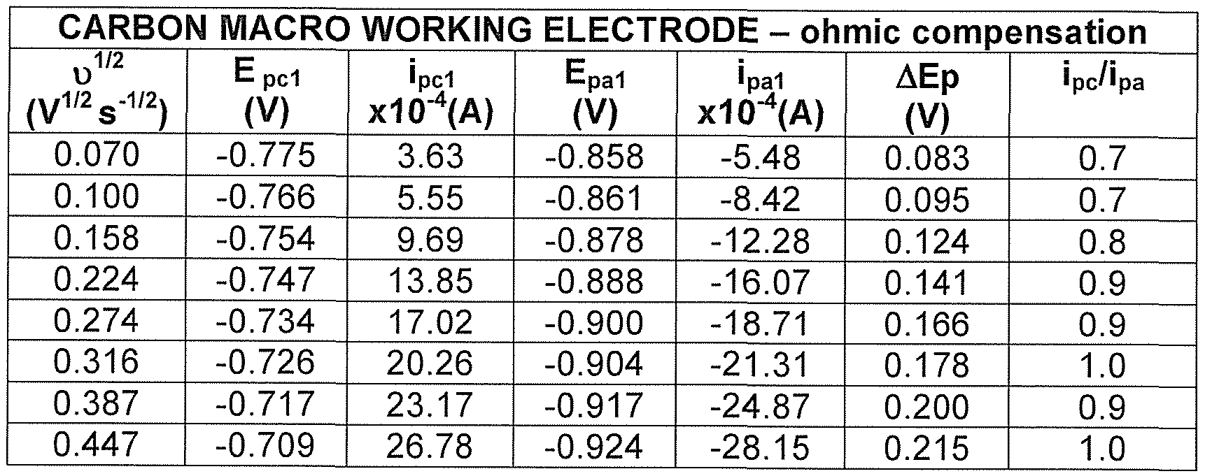
Table 28a - FIRST OXIDATION/REDUCTION
CARBON MACRO WORKING ELECTRODE - ohmic compensation
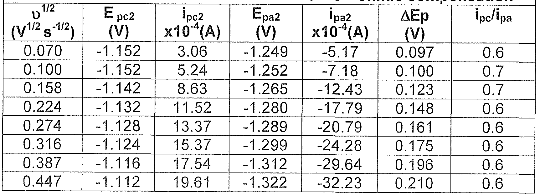
Table 28b - SECOND OXIDATION/REDUCTION
PLATINUM MACR( D WORKIN G ELECT ¾ODE - ohmic compensation
01/2 E pci ipd Epa1 ipal ΔΕρ ipc/ipa
(V1/2 s-1'2) (V) xlO^A) (V) xl O^A) (V)
0.070 -0.782 3.59 -0.844 -3.69 0.062 1 .0
0.100 -0.779 5.95 -0.838 -7.88 0.059 0.8
0.158 -0.774 12.25 -0.837 -12.58 0.063 1 .0
0.224 -0.777 17.75 -0.837 -18.1 1 0.060 1 .0
0.274 -0.777 20.85 -0.839 -21.72 0.062 1.0
0.316 -0.777 26.79 -0.835 -20.48 0.058 1 .3
0.387 -0.774 29.73 -0.840 -30.15 0.066 1 .0
0.447 -0.772 38.73 -0.840 -34.80 0.068 1 .1
Table 29a - FIRST OXIDATION/REDUCTION

GOLD MACRO WORKING ELECTRODE- ohmic compensation υ1/2 E pd ipd Epa1 ipal ΔΕρ ipc/ipa (V1/2 s-1/2) (V) x10"4(A) (V) x10"4(A) (V)
0.070 -0.814 4.67 -0.875 -5.45 0.061 0.9
0.100 -0.805 7.17 -0.866 -9.95 0.061 0.7
0.158 -0.807 1 1 .15 -0.874 -14.12 0.067 0.8
0.224 -0.812 17.18 -0.870 -18.35 0.058 0.9
0.274 -0.815 21 .15 -0.873 -23.35 0.058 0.9
0.316 -0.812 25.46 -0.873 -28.36 0.068 0.9
0.387 -0.812 32.70 -0.874 -32.49 0.062 1 .0
0.447 -0.808 34.86 -0.875 -33.00 0.067 1 .1
Table 30a - FIRST OXIDATION /REDUCTION
GOLD MACRO WORKING ELECTRODE - ohmic compensation

Table 30b - SECOND OXIDATION/REDUCTION As the data shown previously demonstrates the CV of 0.01 M
[P14666][AQS] in 0.1 M TBATFB ACN exhibits a reversible two- step, two- electron reduction/oxidation profile which occurs at negative potentials. Again the diffusion coefficients for the systems have been calculated from plots of υ1/2 vs. ipC (Figures 20a - 20c) and are summarised in Table 31. Using a carbon macro working electrode the slope = 6.183x10"3 and the diffusion coefficient = 1.35x10"4 cm2 s"1. Using a platinum macro working electrode the slope = 8.945x10"3 and the diffusion coefficient = 3.46x10"3 cm2 s~1. Using a gold macro working electrode the slope 8.390x10"3 and the diffusion coefficient = 3.04x10"3 cm2 s"1.

Table 31
(b) 0.01 M rP14666lfAQSl in pure fP14666irNTF?1
An example of a CV obtained using 0.01 M [P14666][AQS] in pure
[P14666][NTF2] is shown in Figure 21. The working electrode used was a carbon macro electrode; Ag/AgCI reference and Pt wire auxiliary electrode were also used. Tables 32 - 34 show a summary of the key
electrochemical data obtained from the CV of this solution using different working electrodes.


Table 32b - SECOND OXIDATION/REDUCTION
PLATINUM MACRO WORKIN G ELECT RODE - o imic compensation υ1/2 E pd ipd Epa1 ipal ΔΕρ ipc/ipa (V1 2 s-1 2) (V) x10"4(A) (V) xlO^A) (V)
0.070 -0.678 0.13 -0.738 -0.13 0.060 1 .0
0.100 -0.669 0.20 -0.735 -0.18 0.066 1 .1
0.158 -0.654 0.30 -0.753 -0.29 0.099 1 .0
0.224 -0.642 0.43 -0.758 -0.37 0.1 16 1 .2
0.274 -0.642 0.53 -0.762 -0.46 0.120 1 .2
0.316 -0.630 0.65 -0.772 -0.52 0.142 1 .3
0.387 -0.624 0.83 -0.773 -0.54 0.149 1 .5
0.447 -0.61 1 0.90 -0.779 -0.68 0.168 1 .3
Table 33 - FIRST OXIDATION/REDUCTION
GOLD MACRO WORKING ELECTRODE- ohmic compensation

Table 34 - SECOND OXIDATION/REDUCTION
The reduction and re-oxidation of 0.01 M [P14666][AQS] in pure
[P14666][NTF2] is the same as that which has previously been observed in 0.1 M TBATFB ACN. Unlike the naphthaquinone equivalent which displayed irreproducible voltammetry the anthraquinone derivative appears to display more reproducible voltammetry, however, it should be noted that there are some inconsistencies which became evident over time and as the working electrode is varied. Investigations into these effects are continuing at present.
The diffusion coefficients for 0.01 M [P14666][AQS] in pure [P14666][NTF2] obtained from Figures 22a - 22c are shown in Table 35. Using a carbon working macro electrode the slope = 2.323x10"4 and the diffusion coefficient = 1 .90x10"7 cm2 s"1. Using a platinum macro working electrode the slope = 2.102x10"4 and the diffusion coefficient = 1 .91x10~6 cm2 s~1. Using a gold macro working electrode the slope = 2.24x10"4 and the diffusion coefficient = 2.17x10"6 cm2 s"1.

(c) Pure [P146661fAQSl
Like the hydro- and naphtha- derivatives no useful information about the reduction and re-oxidation of this RTIL could be derived from the CV of this material, again the underlying cause is thought to be the extreme viscosity of this RTIL (viscosity at 50°C is 1 151 Cp) which results in mass transport to the electrode being hindered.
Example 9 - rC14H30N HQS1
(a) 0.01 M rC14H30NlfHQSl in 0.1 M TBATFB ACN
An example of the CV of 0.01 M [C14H30N][HQS] in 0.1 M TBATFB ACN using a carbon macro electrode, Ag/AgCI reference and Pt wire auxiliary is shown in Figure 23. The key electrochemical data obtained from the analysis of this solution using different working electrodes is summarised in Tables 36 - 39.
CARBO H MACRO WORKING ELECTRODE - ohmic compensation υ1/2 E pc Ipc Epa Ipa ΔΕρ ipc/'pa (V1/2 s-1/2) (V) x10**(A) (V) x10'4(A) (V)
0.070 0.958 5.23 - - - -
0.100 0.970 8.26 0.426 -1 .02 0.544 8.1
0.158 0.998 16.67 0.385 -3.00 0.613 5.2
0.224 1 .026 22.51 0.361 -9.79 0.665 2.3
0.274 1.050 22.67 0.338 -13.82 0.712 1.9
0.316 1 .080 29.90 0.276 -15.09 0.804 1.9
0.387 1 .098 34.46 0.288 -19.37 0.810 1 .8
0.447 1 .1 16 38.00 0.273 -23.12 0.843 1.6
Table 36

GOLD MACRO WORKING ELECTRODE - ohmic com ensation

Table 38

Table 39
A 0.01 M solution of [C14H30N][HQS] in 0.1 M TBATFB ACN exhibits a quasi-reversible two electron oxidation/reduction. This type of behaviour is identical to that which has previously been observed for the other hydroquinones. A summary of the diffusion coefficients which have been calculated for macro electrodes from the slope of Figures 24a - 24c are shown in Table 40. Using a carbon macro electrode the slope = 8.765x10 3 and the diffusion coefficient = 2.71 x1 0"8 cm2 s"1. Using a platinum macro electrode the slope = 1 .447x10"2 and the diffusion coefficient = 9.04x10"7 cm2 s"1. Using a gold macro electrode the slope = 1 .373x1 0~2 and the diffusion coefficient = 8.14x1 0"7 cm2 s'

Table 40
(b) 0.01 M [C14H30N1fHQS1 in pure fC14H30N1[NTF?1
An example of the CV of this solution at different sweep rates is shown in
Figure 25. The key electrochemical parameters obtained from the
analysis of the CV of this solution using different working electrodes are shown in Tables 41 - 44.
CARBON MACRO WORKING ELECTRODE - ohmic compensation

Table 41 a
CARBON MACRO WORKING ELECTRODE - ohmic compensation

Table 41 b

0.316 0.920 10.56
0.387 0.948 12.13
0.447 0.973 13.62
Table 42a

GOLD MACRO WORKING ELECTRODE - ohmic compensation
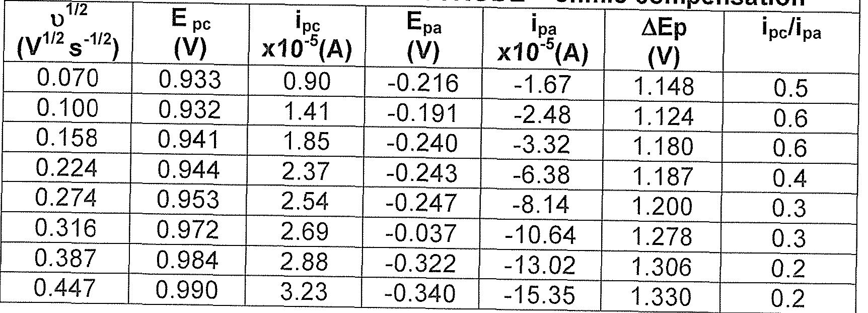
Table 43a
GOLD MACRO V VORKING ELECTRODE - ohmic compensation
1/2
pc 'pc F tpa 'pa ΔΕρ •pc/ipa
(V) x10"5(A) (V) x10"5(A) (V)
0.070 0.368 1 .49 -0.690 -0.58 1 .058 2.6
0.100 0.368 1 .91 -0.690 -0.70 1.058 2.7
0.158 0.389 2.85 -0.716 -1 .19 1.105 2.4
0.224 0.407 3.53 -0.734 -1 .58 1.141 2.2
0.274 0.421 3.58 -0.755 -1.87 1 .176 1.9
0.316 0.445 4.58 -0.785 -3.28 1.230 1.4
0.387 0.463 4.23 -0.779 -3.78 1.242 1.1
0.447 0.475 4.52 -0.776 -3.87 1.251 1.2
Table 43b

Table 44
As the voltammetry of this material has shown this solution exhibits untypical electrochemistry for the oxidation and re-reduction of a hydroquinone species. The exact cause of this effect is not known however, it is thought to be due to one of two effects - either the presence of chloride or a form a self electro-catalysis which has previously been identified in hydroquinone's in aqueous un-buffered media (Chaudhari et al.)5. The effect is essentially caused by the development of a surface confined quinone layer at the electrode surface which results in the hydroquinone getting oxidised at two different catalytic centres. This is results in the presence of two oxidation peaks which are attributed to 'catalysis by normal quinone and catalysis by reactive quinone'. Obviously further testing is needed to investigate this effect. The diffusion
coefficients were calculated using the method described previously and using Figures 26a - 26c and are summarised in Table 45. Using a carbon macro electrode the slope = 2.171 x10"4 and the diffusion coefficient = 1 .66x10"11 cm2 s~1. Using a platinum macro electrode the slope =
3.867x10"4 and the diffusion coefficient = 6.46x10"10 cm2 s" 1. Using a gold macro electrode the slope = 5.674x10"5 and the diffusion coefficient = 1 .39x10"11 cm2 s"1.

Example 10 - rC14H30NUAQS1
(a) 0.01 M rC14H30N1iAQSl in 0.1 M TBATFB ACN
An example of a CV for this solution is shown in Figure 27 which also shows how the voltammetry changes as result of sweep rate. The electrochemical data for this material is summarised in Tables 46 - 48.
CARBON MACRO WORKING ELECTRODE - ohmic compensation

Table 46a

Table 46b

Table 47a
PLATINUM MACRO WORKING ELECTRODE - ohmic com ensation

Table 47b
GOLD MACRO WORKING ELECTRODE - ohmic compensation

Table 48a

Table 48b
As the analysis of 0.01 M [C14H30N][AQS] in 0.1 M TBATFB ACN has shown this solution exhibits quasi-reversible electrochemistry which is typical of an anthraquinone. The reduction/re-oxidation occurs in two steps at negative potentials. The diffusion coefficients have been calculated using Figures 28a - 28c and are summarised in Table 49. Using a carbon macro electrode the slope = 8.154x10"3 and the diffusion coefficient = 2.87x10"3 cm2 s"1. Using a platinum macro electrode the slope = 8.996x10"3 and the diffusion coefficient = 3.49x10'3 cm2 s"1. Using
a gold macro electrode the slope = 1 .074x10"2 and the diffusion coefficient = 4.07x10"4 cm2 s 1.

Table 49
(b) 0.01 M rC14H30N1fAQSl in pure iC14H30NirNTF?1
A summary of the cyclic voltammetry of this solution is shown in Figure 29. The corresponding electrochemical data is summarised in Table 50. The slope = 4.553x10"4 and the diffusion coefficient = 7.31 x10"7 cm2 s"1.

Table 50a
CARBON MACRO WORKING ELECTRODE - ohmic compensation υ1/2 E pc 'PA C Epa Ipa ΔΕρ ipc/ipa (V 2 s"1/2) (V) x1<T*(A) (V) x10 4(A) (V)
0.070 -1.249 0.20 -1 .316 -0.35 0.067 0.6
0.100 -1.245 0.30 -1 .318 -0.50 0.073 0.6
0.158 -1 .246 0.46 -1 .315 -0.78 0.069 0.6
0.224 -1 .241 0.68 -1 .31 1 -1.10 0.070 0.6
0.274 -1 .235 0.79 -1.309 -1.30 0.074 0.6
0.316 -1.232 0.89 -1.281 -1.31 0.049 0.7
0.387 -1.227 1 .18 -1.298 -1.83 0.071 0.6
0.447 -1.231 1.34 -1.304 -2.07 0.073 0.6
Table 50b
As the CV of 0.01 [C14H30N][AQS] in pure [C14H30N][NTF2] has shown the same type of reduction/oxidation is observed as that which was previously identified in acetonitrile. The diffusion coefficient calculated for this solution using a carbon macro electrode (Figure 30) was 7.31 x10"7
2 -1
cm s . Example 11 - A brass electrochemical cell
A prototype cell which allowed the testing of the chosen redox active ionic liquid couple was designed and built. The cell body was constructed from brass. This cell was basically a compact version of an H shaped cell which is conventionally used to study transport through membranes. It consisted of two chambers which were separated by a protonated membrane (the membrane is used to facilitate proton transfer and to ensure the two components remain separated). Each chamber was filled with one of the redox active ionic liquids and the cell connected through simple screws to a potentiostat. This is shown in Figure 31 , which comprises:
20: plastic screws to hold two cell halves together,
22: membrane sandwiched between two cell halves
24: metal screw to provide contact
26: brass cell body
28: inner cavity to hold ionic liquid.
There were several problems encountered with the use of this cell. For example, initial testing showed that the brass used to construct the cell had a tendency to interact with the quinones used and to become very easily tarnished. This effect could not be reversed with even very aggressive cleaning. In addition to this, testing indicated that the cell had a high resistance.
Effect of membrane type
The initial plan was to use commercially bought fuel cell membranes with carbon deposited on both sides to act as both the membrane and the electrodes within the cell. It was found however, these membranes were unsuitable for use with the highly viscous RTILs as they appeared to hinder proton transport, therefore it was decided to replace the carbon membranes with simple Nafion 1 17 membranes (DuPont) which were manually protonated by boiling in acid. Testing showed that these membranes performed significantly better than the carbon based membranes. Additional electrodes in the form of the pieces of platinum mesh were added to the cell to replace the carbon used previously. Example 12 - PTFE cell
The cell described in Figure 31 was constructed using a PTFE body instead of a brass body - this was done to eliminate the adverse chemical reactions which were observed using brass and to try and improve the performance of the cell. In addition, the cell the electrode arrangement within the cell was also altered, i.e. a platinum mesh electrode was added into each cell half. The platinum was placed in a number of positions within the cell including in direct contact with the membrane but this arrangement was not found to be suitable, i.e. there was no change to the open circuit potential when different currents were applied to the cell. Instead, the platinum mesh was carefully folded to create small 'cups'
which were placed in the cavities within the PTFE cell in direct contact with the ionic liquids. A small piece of platinum/iridium wire was threaded through each mesh to the exterior of cell and the wire was connected to the potentiostat.
Several standard electrochemical testing methods were tested to examine cell performance including cyclic voltammetry, electrical impedance spectroscopy, and galvanic coulometry. The experiments were performed by measuring the open circuit potential of the cell, then applying a small current or potential and then re-measuring the open circuit potential. The results are summarised below.
Cyclic voltammetry
In all of the cyclic voltammetry experiments which were performed using the quinone couples a resistor response was obtained (Figure 32). Given the nature of the liquids involved and the cell set-up used this was not unexpected i.e. the high viscosity of the pure quinone ionic liquids hinders mass transport. It was therefore, concluded that as expected cyclic voltammetry could not be used to gain a significant amount of information about cell performance. The CV was recorded using the HQS side of the cell as the working electrode and the AQS side of the cell as the counter electrode. The reference was clipped to the counter electrode. The CV was recorded at 100mVs"1 from 0 to 1300 to -1800 mV. Electrical Impedance spectroscopy
The results from the impedance spectroscopy of the cell were mixed - but generally displayed a semi-circle in the high frequency region of the plot. The lower frequency region was typically very noisy but there was no obvious Warburg behaviour. An example of the plot obtained is shown in Figure 33. The impedance spectrum was recorded using the HQS side of
the cell as the working electrode and the AQS side of the cell as the counter electrode. The reference was clipped to the counter electrode. The spectrum was recorded from 100 kHz to 200 Hz. The applied potential was 1000mV.
Effect of applied potential on the EIS
It was also found that changing the applied potential had no significant effect on the type of impedance response that was observed. The impedance for each cell half at different applied potentials was studied. The results obtained are shown in Table 51 a (hydroquinone as working electrode, counter and reference electrodes = [P14666][AQS]) and Table 52a (anthraquinone as working electrode, counter and reference electrodes = [P14666][HQS]). Tables 51 b and 52b show the change to the OCP following each impedance spectrum. As Tables 51 b and 52b show the open circuit potential only changes by a small amount after the impedance has been run and decays very quickly again back to near its original value.
Applied R1 (kohms.cm2) R2 (kohms.cm ) R2 - R1 Potential (mV) (kohms.cm2)
Free 1 .107 271.30 270.19
200 0.942 278.70 277.76
400 1 .222 267.00 265.78
600 2.181 272.80 270.62
800 1 .008 269.20 268.19
1000 0.972 268.70 267.73
1200 1 .603 266.60 265.00
-200 5.426 214.80 209.37
-400 1 .265 253.80 252.54
-600 1 .246 248.50 247.25
-800 1 .234 257.00 255.77
-1000 1.719 254.90 253.18
-1200 2.246 239.90 237.65
-1400 2.273 237.9 235.63
Table 51a

Table 51 b

Table 52a
Applied Potential OCP before (mV) OCP after (mV)

Table 52b
Effect of applying a current to the open circuit potential
A potentiostat was used to apply small currents to the cell and to measure the change which occurred to the open circuit potential of the cell as a result. The results of the trials performed are shown below (Example 13 and Example 14). It is important to note that as expected once the cell had been subjected to a change it never regained its initial open circuit potential. In addition to this once a current has been applied the OCP
(which begins to record immediately after this) decays extremely quickly in the initial few minutes before the decay begins to level off and becomes much slower (see Figure 34 which shows an example of the fall in open circuit potential after a current of 100μΑ has been applied for three hours) - this indicates that it takes the system increasingly longer to return to its equilibrium state i.e. when a current is applied for long times a larger amount of material is converted to its oxidised or reduced state (see following section which shows the relationship between the amount of charge that is passed and the amount of material which is oxidised or reduced at the electrode surface). As the results also indicate the two cell halves respond to the applied current in the same way.
Example 13
Working electrode pure fP146661fHQS], auxiliary and reference pure fP14666irAQSl. PTFE cell.
Sequence 1
· Initial Open circuit of cell (at rest) (recorded over 5 mins):305 - 307 mV
• Application of 10ΟμΑ for 1 minute
• Open circuit after application of charge (recorded over 20 minutes):
1335 - 499 mV Sequence 2
• Initial open circuit of cell (10 minutes): 251 - 278 mV
• Application of 100μΑ for 10 minutes
• Open circuit after charging (recorded over 20 mins): 1463 - 1266 mV
• Open circuit after further 60 minutes: 1230 - 1 1 1 1 mV
· Open circuit after further 60 minutes: 1052 - 760 mV
• Open circuit after further 60 minutes: 748 - 614 mV
Sequence 3
• Initial open circuit potential of cell (recorded over 5 mins): 411 - 414 · Application of 100μΑ for 30 minutes
• Open circuit potential recorded over 60 minutes: 1420 - 1266 mV
Sequence 4
• Open circuit potential recorded over further 60 mins: 1263 - 1222 mV · Application of 100μΑ for 60 minutes
• Open circuit recorded over 120 minutes: 1397 - 1279 mV
• Measured manual discharge of system with voltmeter over 60 minutes:
1238 - 1218 mV
Sequence 5
Open circuit potential (recorded over 10 minutes): 672 - 667 mV Application of 100μΑ for 120 minutes
Open circuit potential recorded after charging (recorded over 120 minutes): 1382 - 1278 mV
Application of l OOpA for 180 minutes
Open circuit potential recorded over 60 minutes: 1387 - 1291 mV
Manually measured further decay of potential using voltmeter
Initial potential: 1228 mV
Potential after further 120 minutes: 1168 mV
Potential after further 60 minutes: 1 147 mV
Potential after further 60 minutes: 1 127 mV
Potential after further 60 minutes: 1 119 mV
Potential after further 60 minutes: 1 112 mV
Continued to manually measure drop of potential over a further 2 days, during which the potential dropped to 557 mV.
Sequence 6
• Open circuit potential (recorded over 5 minutes): 437 - 439 mV
• Application of 100 μΑ for 240 minutes
• Open circuit potential recorded after charging (recorded over 60
minutes): 141 1 - 1347 mV
Figure 35 shows the change in the open circuit potential before and after the application of 100μΑ for 4 hours. Table 53 shows the calculation of charge passed and mass of material converted during charging for
[P14666][HQS] as working electrode and [P14666][AQS] as auxiliary and reference electrodes.
Current Time Charge Number Mass % Mass
Applied (seconds) (C mol"1) of moles (g) converted

Table 53 - Relative molecular mass of [P14666][HQS] = 675; to calculate % mass converted assume that mass of [P14666][HQS] in cell was 1 .3g, therefore Mass/Mass converted * 100 = % Mass converted.
Example 14
Working electrode pure fP14666irAQS1, auxiliary and reference pure
[P14666irHQSl. PTFE cell. Sequence 1
β Initial open circuit potential (5 minutes): -237 - (-236) mV
• Application of -100μΑ for 1 minute
• Open circuit potential after charging (20 minutes): -1234 - (-610) mV
• Open circuit potential recorded after 008 minutes: -228 mV
Sequence 2
• Initial open circuit potential (5 minutes): -252 - (-255) mV
• Application of -100μΑ for 10 minutes
• Open circuit potential (after charge) (recorded over 20 minutes): -1448 - (-1254) mV
• Open circuit potential recorded (over further 60 minutes): -1250 - (- 1095) mV
• Open circuit potential (10 minutes): -1091 - (-1060) mV
o Application of -100μΑ for 30 minutes
· Open circuit potential after charging (60 minutes): -1467 - (-1290) mV
• Open circuit potential recorded (over further 60 minutes): -1289 - (- 1250) mV
• Open circuit potential (10 minutes): -1248 - (-1243) mV
• Application of -1 ΟΟμΑ for 60 minutes
· Open circuit potential after charging (60 minutes): -1459 - (-1326) mV
• Open circuit potential after further 8240 minutes (voltmeter): -352 mV
Sequence 3
« Initial Open circuit potential (10 minutes): -385 - (-392) mV
· Application of -100μΑ for 180 minutes
• Open circuit potential after charging (120 mins): -1442 - (-1316) mV » Open circuit potential after further 60 minutes: -1313 - (-1291) mV
• Open circuit potential after further 1 153 minutes: -686 mV
Sequence 4
• Initial Open circuit (10 minutes): -669 - (-686) mV
• Application of -100μΑ for 300 minutes
• Open circuit potential after charging (60 minutes): -1429 - (-1362) mV · Open circuit potential after a further 1010 minutes: -1096 mV
Figure 36 shows the change in the open circuit potential before and after the application of -100μΑ for 5 hours. Table 54 shows the calculation of charge passed and mass of material converted during charging for
[P14666][AQS] as working electrode and [P14666][HQS] as auxiliary and reference electrodes.


Table 54 - Relative molecular mass = 770; to calculate % mass converted assume that mass of [P14666][HQS] in cell was 1 .09g, therefore
Mass/Mass converted * 100 = % Mass converted.
Example 15 - Glass cell
A glass version of the cell described above was also prepared. It should be noted that although the cell body has changed the working principles of the cell remain the same, i.e. the membrane type and electrodes used were the same. The key advantages of using a cell of this type are that filling the cell is much simpler and a visual check can be kept on the cell components. The same types of trials as those performed previously using the PTFE cell were performed. A sample of the results for the oxidation of hydroquinone side of the cell are summarised below. As a comparison of these results with the results shown previously for the PTFE cell indicate as expected the two cells act in the same way.
Effect OCP
Initial OCP 178 - 189 mV
OCP before 180 - 187 mV
Gal coul 1 mA 1 min
OCP after 1.48V - 539 mV
OCP before 441 - 288 mV
Gal coul 1 mA 5 min
OCP after 1.12V - 660 mV
OCP before 528 - 474 mV
Gal coul 1 mA 10 min
OCP after 1 .32 - 81 1 mV
OCP at end of experiments 777 - 653 mV
OCP (24 hours) 233 - 252 mV
Table 55
As the testing of the hydroquinone/anthraquinone battery couple has shown it has been possible to generate around 1 .4V from this system following relatively short periods of charging. Furthermore it has been possible to sustain this charging over a number of repetitive cycles and with each subsequent charge the decay of the open circuit potential becomes less and less i.e. there is an accumulation of charge held in the cell.
The results obtained therefore demonstrate that these types of molecules can be employed successfully in electrochemical devices such as batteries. All documents referred to in this specification are hereby incorporated by reference. Various modifications and variations to the described embodiments of the invention will be apparent to those skilled in the art without departing from the scope and spirit of the invention. Although the invention has been described in connection with specific preferred embodiments, it should be understood that the invention as claimed should not be unduly limited to such specific embodiments. Indeed, various modifications of the described modes of carrying out the invention which are obvious to those skilled in the art are intended to be covered by the present invention.
References
1 . Matsuda, H., Ayabe Y., Z. Electrochem., 59 (1955) 494.
2. Astudillo, P. D., Tiburcio, J., Gonzalez, F. J., J. Electroanal. Chem., 604 (2007) 57.
3. Bard, A. J., Faulkner, L. R., Electrochemical Methods: Fundamentals and Applications (Second Edition, 2001 ) New York, Wiley, ISBN:9- 78047104372-9, p231 .
4. Bard, A. J., Faulkner, L. R., Electrochemical Methods: Fundamentals and Applications (Second Edition, 2001) New York, Wiley, ISBN: 9-
78047104372-9, p24.
5. Chaudhari, V. J., Bhat, M. A., Ingole, P. P., Haram, S. K., Electrochem. Comm., In press (2009).
Claims
1. A rechargeable battery comprising a first electrode and a second electrode separated by an ion-conducting barrier, wherein in its charged state, said rechargeable battery includes a molten salt comprising quinone or quinone derivative A having the structure of Formula I at the first electrode and a molten salt comprising hydroquinone or hydroquinone derivative B having the structure of Formula II or the structure of Formula III at the second electrode:
Formula I 
 wherein during the discharging process, charge flows from the second electrode to the first electrode through the reduction of quinone or quinone derivative A according to reaction scheme a, and the oxidation of hydroquinone or hydroquinone derivative B according to reaction scheme 2a or reaction scheme 3a:

Reaction Scheme 3a wherein R1 to R7 may independently be A; hydrogen; C1 to 10 linear, branched chain or cyclic alkyl groups; aryl; hetero cycles; CI, Br, I, CN; OH or NO2 wherein said alkyl and aryl substituents may themselves be substituted or unsubstituted; if the quinone or quinone derivative is anionic or the hydroquinone or hydroquinone derivative is anionic A represents SO3~ or COO", O-HPO3 " or O-PO3 2" or R-O-SO3"; and
if the quinone or quinone derivative is cationic or the hydroquinone or hydroquinone derivative is cationic either: A and optionally one or more of R1 - R7 independently represent imidazolium, piperidinium, pyridinium, phosphonium, pyrazinium, quaternary amine, ammonium species or derivatives thereof; or one or more of the ring atoms is a quaternised heteroatom and A represents hydrogen; a C1 to 10 linear, branched chain or cyclic alkyl group; an aryl group; a heterocycle group; CI, Br, I, CN; OH or NO2 wherein said alkyl and aryl substituents may themselves be substituted or unsubstituted.
2. The battery of claim 1 wherein in its uncharged state, the
rechargeable battery includes a molten salt comprising quinone or quinone derivative A in its reduced form, having the structure of Formula IB at the first electrode, and a molten salt comprising hydroquinone or
hydroquinone derivative B in its oxidised form, having the structure of Formula MB or Formula IIIB at the second electrode:

Formula IB


wherein during the charging process charge flows from the first electrode to the second electrode through the oxidation of the reduced form of quinone or quinone derivative A according to reaction scheme 1 b and the reduction of the oxidised form of hydroquinone or hydroquinone derivative B according to reaction scheme 2b or 3b:

Reaction Scheme 1 b


wherein A and R1 to R7 are as defined in claim 1 .
3. The battery of either one of claims 1 and 2 wherein hydroquinone or hydroquinone derivative B has the structure of Formula III.
4. The battery of any preceding claim wherein the difference in redox potential (ΔΕ) between the redox reactions of quinone or quinone derivative A and hydroquinone or hydroquinone derivative B is greater than 0.0 V-.
5. The battery of any preceding claim wherein the A group of quinone or quinone derivative A is -S03 ", COO", O-HPO3, -O-PO3 2 or R-O-SO3 ".
6. The battery as claimed in either one of claims 1 and 2 wherein hydroquinone or hydroquinone derivative B has any one of the structures as shown below: 
7. The battery of any preceeding claim wherein the molten salts are in the form of ionic liquids having a melting point of 100 °C or less.
8. The battery of any one of claims 1 to 5 wherein the anion of the molten salt is quinone or quinone derivative A or hydroquinone or hydroquinone derivative B and the cation of the molten salt has any one of the structures as shown below:
>


+
H3C C4H,
, or  , or a combination thereof.
9. The battery of any one of claims 1 to 4 wherein the cation of the molten salt is quinone or quinone derivative A or hydroquinone or hydroquinone derivative B, and the anion of the molten salt is PF6, tetrafluoroborate, bistriflimide, triflate, fluoroalkylsulfonates, nitrate, hexafluorophosphate, carboxylic acids, phosphate, alkylphosphates, dicyanamide, HS0 ", SO3", thiocyanate or a combination thereof.
10. The battery of any preceding claim wherein a current of up to 0.5 amps per cm2 of electrode area can be generated therefrom.
1 1. The battery of any preceding claim wherein a single cell voltage of up to 1.5 volts can be generated therefrom.
12. The battery of any preceding claim wherein the energy storage capacity of the battery is at least 0.01 Amp hour per cm3 of quinone or quinone derivative, or hydroquinone or hydroquinone derivative,
13. The battery of any preceding claim wherein the battery of the present invention recharges to at least 99 % of its initial redox potential
14. The battery of any preceding claim being charge and mass balanced.
15. The battery of any preceding claim wherein the redox reactions of reaction schemes 1 a, 2a and 3a proceed at temperatures of 100 °C or less.
16. The battery of any preceding claim wherein said battery does not comprise any molten metal.
17. The battery of any preceding claim wherein the one or more of the electrodes comprise a platinum electrode.
18. The battery of claim 7 wherein one or more of the electrodes comprise a platinum mesh.
19. The battery of any preceding claim wherein the ion-conducing barrier is a solid polymer electrolyte.
20. The battery of claim 19 wherein the solid polymer electrolyte is a perfluorinated polymer comprising fixed sulfonate groups.
21. The battery of claim 20 wherein the perfluorinated polymer comprising fixed sulfonate groups is protonated.
22. The battery of any preceding claim wherein the molten salt further comprises a further ionic liquid.
23. The battery of claim 22 wherein the further ionic liquid comprises the same counter-ion as the quinone or quinone derivative A or hydroquinone or hydroquinone derivative B.
24. The battery of any one of claims 22 or 23 wherein the further ionic liquid comprises bis(trifluoromethyl-sulphonyl) imide as an anion.
25. The battery of any one of claims 1 to 21 wherein the molten salt consists essentially of the quinone or quinone derivative A, or the hydroquinone or hydroquinone derivative B, and an anionic or cationic counter-ion.
26. The use of a molten salt comprising quinone or quinone derivative A having the structure of Formula I, and a molten salt comprising
hydroquinone or hydroquinone derivative B having the structure of Formula II or the structure of Formula III in energy storage applications: wherein energy is stored through the flow of charge from a first electrode to a second electrode through the oxidation of the reduced form of quinone or quinone derivative A according to reaction scheme 1 b and the reduction of the oxidised form of hydroquinone or hydroquinone derivative B according reaction scheme 2b or 3b and energy is discharged through the flow of charge from the second electrode to the first electrode through the reduction of quinone or quinone derivative A according to reaction scheme a and the oxidation of hydroquinone or hydroquinone B according to reaction scheme 2a or 3a.
27. A method of producing a rechargeable battery comprising the steps of: providing a first electrode and a second electrode, separated by an ion- conducting barrier;
providing a molten salt comprising quinone or quinone derivative A having the structure of Formula I at the first electrode, and a molten salt comprising hydroquinone or hydroquinone derivative B having the structure of Formula II or the structure of Formula III at the second electrode.
28. The method of claim 27 wherein the battery as claimed in any one of claims 1 to 25 is formed.
Applications Claiming Priority (2)
| Application Number | Priority Date | Filing Date | Title |
|---|---|---|---|
| GB1006488.9 | 2010-04-19 | ||
| GBGB1006488.9A GB201006488D0 (en) | 2010-04-19 | 2010-04-19 | Battery |
Publications (1)
| Publication Number | Publication Date |
|---|---|
| WO2011131959A1 true WO2011131959A1 (en) | 2011-10-27 |
Family
ID=42245416
Family Applications (1)
| Application Number | Title | Priority Date | Filing Date |
|---|---|---|---|
| PCT/GB2011/050659 Ceased WO2011131959A1 (en) | 2010-04-19 | 2011-03-31 | Redox battery |
Country Status (2)
| Country | Link |
|---|---|
| GB (1) | GB201006488D0 (en) |
| WO (1) | WO2011131959A1 (en) |
Cited By (32)
| Publication number | Priority date | Publication date | Assignee | Title |
|---|---|---|---|---|
| WO2013006029A1 (en) * | 2011-07-01 | 2013-01-10 | Mimos Berhad | Method and apparatus for energy harvesting in a closed environment |
| US20130224538A1 (en) * | 2012-02-28 | 2013-08-29 | Uchicago Argonne Llc | Organic non-aqueous cation-based redox flow batteries |
| WO2013151588A1 (en) * | 2012-04-04 | 2013-10-10 | Battelle Memorial Institute | Hybrid energy storage systems utilizing redox active organic compounds |
| US20140370403A1 (en) * | 2013-06-17 | 2014-12-18 | University Of Southern California | Inexpensive metal-free organic redox flow battery (orbat) for grid-scale storage |
| WO2015048550A1 (en) | 2013-09-26 | 2015-04-02 | President And Fellows Of Harvard College | Quinone and hydroquinone based flow battery |
| KR20150044922A (en) * | 2012-08-14 | 2015-04-27 | 예나바테리스 게엠베하 | Redox flow cell comprising high molecular weight compounds as redox pair and semipermeable membrane for storage of electrical energy |
| KR20150063467A (en) * | 2012-09-26 | 2015-06-09 | 프레지던트 앤드 펠로우즈 오브 하바드 칼리지 | Small organic molecule based flow battery |
| WO2015148357A1 (en) * | 2014-03-24 | 2015-10-01 | Cornell University | Symmetric redox flow battery containing organic redox active molecule |
| WO2016078492A1 (en) * | 2014-11-17 | 2016-05-26 | 中国科学院大连化学物理研究所 | Quinone polyhalide flow battery |
| WO2016144909A1 (en) * | 2015-03-06 | 2016-09-15 | President And Fellows Of Harvard College | HIGH pH ORGANIC FLOW BATTERY |
| JP2016175882A (en) * | 2015-03-20 | 2016-10-06 | 東洋合成工業株式会社 | Organic salts containing ammonium cations |
| US9825323B2 (en) | 2015-01-06 | 2017-11-21 | Toyota Motor Engineering & Manufacturing North America, Inc. | Quinone-based high energy density liquid active material for flow battery |
| JP2018520455A (en) * | 2015-04-01 | 2018-07-26 | フンダシオン セントロ デ インベスティガシオン コオペラティバ デ エネルヒアス アルテルナティバス セイセ エネルヒグネ フンダツィオアFundacion Centro De Investigacion Cooperativa De Energias Alternativas Cic Energigune Fundazioa | Organic electrolyte compounds for redox flow batteries |
| US10263308B2 (en) | 2014-03-24 | 2019-04-16 | Cornell University | Solar flow battery |
| JP2019516781A (en) * | 2016-04-07 | 2019-06-20 | ツェーエムブルー プロイェクト アーゲー | Sulfonated aromatic compounds |
| US10374239B2 (en) | 2016-12-29 | 2019-08-06 | Uchicago Argonne, Llc | Aqueous pyridinium cation-based redox flow batteries |
| US10424805B2 (en) | 2017-08-15 | 2019-09-24 | Uchicago Argonne, Llc | Benzothiophene-based redox molecules for flow battery |
| US10553890B2 (en) | 2017-06-23 | 2020-02-04 | Uchicago Argonne, Llc | Aqueous redox flow batteries |
| US10680280B2 (en) | 2017-09-26 | 2020-06-09 | Toyota Jidosha Kabushiki Kaisha | 3D magnesium battery and method of making the same |
| US10840532B2 (en) | 2017-01-27 | 2020-11-17 | President And Fellows Of Harvard College | Flow battery with electrolyte rebalancing system |
| CN112234195A (en) * | 2019-07-15 | 2021-01-15 | 浙江大学 | A rechargeable and dischargeable aqueous zinc-ion full battery |
| US10910672B2 (en) | 2016-11-28 | 2021-02-02 | Toyota Motor Engineering & Manufacturing North America, Inc. | High concentration electrolyte for magnesium battery having carboranyl magnesium salt in mixed ether solvent |
| WO2021241709A1 (en) * | 2020-05-28 | 2021-12-02 | 株式会社トクヤマ | Polyfunctional quaternary ammonium salt of sulfonic acid having active-hydrogen groups |
| US11271237B2 (en) | 2019-07-29 | 2022-03-08 | Uchicago Argonne, Llc | Organic redox molecules for flow batteries |
| US11450854B2 (en) | 2017-02-13 | 2022-09-20 | Cmblu Energy Ag | Redox flow battery electrolytes |
| US11557786B2 (en) | 2018-10-01 | 2023-01-17 | President And Fellows Of Harvard College | Extending the lifetime of organic flow batteries via redox state management |
| US11724980B2 (en) | 2018-02-09 | 2023-08-15 | President And Fellows Of Harvard College | Quinones having high capacity retention for use as electrolytes in aqueous redox flow batteries |
| EP4227604A1 (en) * | 2022-02-09 | 2023-08-16 | Frank Haese | Device for converting thermal energy of an external heat source into electrical energy |
| US11788228B2 (en) | 2017-02-13 | 2023-10-17 | Cmblu Energy Ag | Methods for processing lignocellulosic material |
| US11831017B2 (en) | 2018-02-13 | 2023-11-28 | Cmblu Energy Ag | Redox flow battery electrolytes |
| US11891349B2 (en) | 2018-02-13 | 2024-02-06 | Cmblu Energy Ag | Aminated lignin-derived compounds and uses thereof |
| US11923581B2 (en) | 2016-08-12 | 2024-03-05 | President And Fellows Of Harvard College | Aqueous redox flow battery electrolytes with high chemical and electrochemical stability, high water solubility, low membrane permeability |
Citations (5)
| Publication number | Priority date | Publication date | Assignee | Title |
|---|---|---|---|---|
| US3238066A (en) * | 1961-11-22 | 1966-03-01 | Union Oil Co | Method of generating electricity using a polyhydric phenol-oxygen fuel cell |
| JP2004043334A (en) * | 2002-07-09 | 2004-02-12 | National Institute Of Advanced Industrial & Technology | New room temperature molten salt and electrochemical device |
| WO2006003395A2 (en) | 2004-06-30 | 2006-01-12 | The Queen's University Of Belfast | Molten salts, method of their production and process for generating hydrogen peroxide |
| RO120939B1 (en) * | 1999-05-27 | 2006-09-29 | Savel Matache | Electrochemical redox cell, process for making the same and process for the regeneration of electrolyte solutions |
| FR2930076A1 (en) * | 2008-04-09 | 2009-10-16 | Univ Joseph Fourier | BIOPILE WITH IMPROVED PERFORMANCE |
-
2010
- 2010-04-19 GB GBGB1006488.9A patent/GB201006488D0/en not_active Ceased
-
2011
- 2011-03-31 WO PCT/GB2011/050659 patent/WO2011131959A1/en not_active Ceased
Patent Citations (5)
| Publication number | Priority date | Publication date | Assignee | Title |
|---|---|---|---|---|
| US3238066A (en) * | 1961-11-22 | 1966-03-01 | Union Oil Co | Method of generating electricity using a polyhydric phenol-oxygen fuel cell |
| RO120939B1 (en) * | 1999-05-27 | 2006-09-29 | Savel Matache | Electrochemical redox cell, process for making the same and process for the regeneration of electrolyte solutions |
| JP2004043334A (en) * | 2002-07-09 | 2004-02-12 | National Institute Of Advanced Industrial & Technology | New room temperature molten salt and electrochemical device |
| WO2006003395A2 (en) | 2004-06-30 | 2006-01-12 | The Queen's University Of Belfast | Molten salts, method of their production and process for generating hydrogen peroxide |
| FR2930076A1 (en) * | 2008-04-09 | 2009-10-16 | Univ Joseph Fourier | BIOPILE WITH IMPROVED PERFORMANCE |
Non-Patent Citations (5)
| Title |
|---|
| ASTUDILLO, P. D., TIBURCIO, J., GONZALEZ, F. J., J., ELECTROANAL. CHEM., vol. 604, 2007, pages 57 |
| BARD, A. J, FAULKNER, L. R.: "Electrochemical Methods: Fundamentals and Applications", 2001, WILEY, pages: 24 |
| BARD, A. J., FAULKNER, L. R.: "Electrochemical Methods: Fundamentals and Applications", 2001, WILEY, pages: 231 |
| CHAUDHARI, V. J., BHAT, M. A., INGOLE, P. P., HARAM, S. K., ELECTROCHEM. COMM., 2009 |
| MATSUDA, H., AYABE Y., Z. ELECTROCHEM., vol. 59, 1955, pages 494 |
Cited By (72)
| Publication number | Priority date | Publication date | Assignee | Title |
|---|---|---|---|---|
| WO2013006029A1 (en) * | 2011-07-01 | 2013-01-10 | Mimos Berhad | Method and apparatus for energy harvesting in a closed environment |
| US20130224538A1 (en) * | 2012-02-28 | 2013-08-29 | Uchicago Argonne Llc | Organic non-aqueous cation-based redox flow batteries |
| US9300000B2 (en) * | 2012-02-28 | 2016-03-29 | Uchicago Argonne, Llc | Organic non-aqueous cation-based redox flow batteries |
| US9130218B2 (en) | 2012-04-04 | 2015-09-08 | Battelle Memorial Institute | Hybrid energy storage systems utilizing redox active organic compounds |
| WO2013151588A1 (en) * | 2012-04-04 | 2013-10-10 | Battelle Memorial Institute | Hybrid energy storage systems utilizing redox active organic compounds |
| CN104321924A (en) * | 2012-04-04 | 2015-01-28 | 巴特尔纪念研究院 | Hybrid energy storage systems utilizing redox active organic compounds |
| KR102091385B1 (en) | 2012-08-14 | 2020-03-20 | 예나바테리스 게엠베하 | Redox flow cell comprising high molecular weight compounds as redox pair and semipermeable membrane for storage of electrical energy |
| KR20150044922A (en) * | 2012-08-14 | 2015-04-27 | 예나바테리스 게엠베하 | Redox flow cell comprising high molecular weight compounds as redox pair and semipermeable membrane for storage of electrical energy |
| CN113555594A (en) * | 2012-09-26 | 2021-10-26 | 哈佛大学校长及研究员协会 | Flow batteries based on small organic molecules |
| KR102392089B1 (en) * | 2012-09-26 | 2022-04-28 | 프레지던트 앤드 펠로우즈 오브 하바드 칼리지 | Small organic molecule based flow battery |
| WO2014052682A3 (en) * | 2012-09-26 | 2015-08-20 | President And Fellows Of Harvard College | Small organic molecule based flow battery |
| JP2019179768A (en) * | 2012-09-26 | 2019-10-17 | プレジデント アンド フェローズ オブ ハーバード カレッジ | Low molecular weight organic compound based flow battery |
| JP2015534708A (en) * | 2012-09-26 | 2015-12-03 | プレジデント アンド フェローズ オブ ハーバード カレッジ | Low molecular organic compound based flow battery |
| CN105308785A (en) * | 2012-09-26 | 2016-02-03 | 哈佛大学校长及研究员协会 | Flow Batteries Based on Small Organic Molecules |
| US20160043423A1 (en) * | 2012-09-26 | 2016-02-11 | President And Fellows Of Harvard College | Small organic molecule based flow battery |
| US20150243991A1 (en) * | 2012-09-26 | 2015-08-27 | President And Fellows Of Harvard College | Small organic molecule based flow battery |
| KR20150063467A (en) * | 2012-09-26 | 2015-06-09 | 프레지던트 앤드 펠로우즈 오브 하바드 칼리지 | Small organic molecule based flow battery |
| US9966622B2 (en) | 2012-09-26 | 2018-05-08 | President And Fellows Of Harvard College | Small organic molecule based flow battery |
| AU2018203801B2 (en) * | 2012-09-26 | 2020-06-18 | President And Fellows Of Harvard College | Small organic molecule based flow battery |
| US10566643B2 (en) | 2013-06-17 | 2020-02-18 | University Of Southern California | Inexpensive metal-free organic redox flow battery (ORBAT) for grid-scale storage |
| CN105409045B (en) * | 2013-06-17 | 2019-02-01 | 南加利福尼亚大学 | Metal-free organic redox flow batteries for grid-scale energy storage |
| US11532830B2 (en) | 2013-06-17 | 2022-12-20 | University Of Southern California | Inexpensive metal-free organic redox flow battery (ORBAT) for grid-scale storage |
| US20170187060A1 (en) * | 2013-06-17 | 2017-06-29 | University Of Southern California | Inexpensive metal-free organic redox flow battery (orbat) for grid-scale storage |
| CN105409045A (en) * | 2013-06-17 | 2016-03-16 | 南加利福尼亚大学 | Inexpensive and metal-free organic redox flow battery (ORBAT) for grid-scale energy storage |
| US9614245B2 (en) | 2013-06-17 | 2017-04-04 | University Of Southern California | Inexpensive metal-free organic redox flow battery (ORBAT) for grid-scale storage |
| US20140370403A1 (en) * | 2013-06-17 | 2014-12-18 | University Of Southern California | Inexpensive metal-free organic redox flow battery (orbat) for grid-scale storage |
| JP2016533613A (en) * | 2013-09-26 | 2016-10-27 | プレジデント アンド フェローズ オブ ハーバード カレッジ | Quinone and hydroquinone flow batteries |
| EP3050151A4 (en) * | 2013-09-26 | 2017-05-17 | President and Fellows of Harvard College | Quinone and hydroquinone based flow battery |
| CN106063017A (en) * | 2013-09-26 | 2016-10-26 | 哈佛大学校长及研究员协会 | Quinone and hydroquinone based flow battery |
| CN106063017B (en) * | 2013-09-26 | 2020-05-19 | 哈佛大学校长及研究员协会 | Quinone- and hydroquinone-based flow batteries |
| WO2015048550A1 (en) | 2013-09-26 | 2015-04-02 | President And Fellows Of Harvard College | Quinone and hydroquinone based flow battery |
| AU2014324647B2 (en) * | 2013-09-26 | 2018-12-20 | President And Fellows Of Harvard College | Quinone and hydroquinone based flow battery |
| JP2020098769A (en) * | 2013-09-26 | 2020-06-25 | プレジデント アンド フェローズ オブ ハーバード カレッジ | Quinone and hydroquinone based flow batteries |
| US20160248114A1 (en) * | 2013-09-26 | 2016-08-25 | President And Fellows Of Harvard College | Quinone and hydroquinone based flow battery |
| KR20160067882A (en) * | 2013-09-26 | 2016-06-14 | 프레지던트 앤드 펠로우즈 오브 하바드 칼리지 | Quinone and hydroquinone based flow battery |
| AU2019201862B2 (en) * | 2013-09-26 | 2020-12-03 | President And Fellows Of Harvard College | Quinone and hydroquinone based flow battery |
| KR102356506B1 (en) * | 2013-09-26 | 2022-01-27 | 프레지던트 앤드 펠로우즈 오브 하바드 칼리지 | Quinone and hydroquinone based flow battery |
| US10847829B2 (en) | 2013-09-26 | 2020-11-24 | President And Fellows Of Harvard College | Quinone and hydroquinone based flow battery |
| WO2015148357A1 (en) * | 2014-03-24 | 2015-10-01 | Cornell University | Symmetric redox flow battery containing organic redox active molecule |
| US10263308B2 (en) | 2014-03-24 | 2019-04-16 | Cornell University | Solar flow battery |
| US10079401B2 (en) | 2014-03-24 | 2018-09-18 | Cornell University | Symmetric redox flow battery containing organic redox active molecule |
| US10446867B2 (en) | 2014-11-17 | 2019-10-15 | Dalian Institute Of Chemical Physics, Chinese Academy Of Sciences | Quinone polyhalide flow battery |
| WO2016078492A1 (en) * | 2014-11-17 | 2016-05-26 | 中国科学院大连化学物理研究所 | Quinone polyhalide flow battery |
| US9825323B2 (en) | 2015-01-06 | 2017-11-21 | Toyota Motor Engineering & Manufacturing North America, Inc. | Quinone-based high energy density liquid active material for flow battery |
| WO2016144909A1 (en) * | 2015-03-06 | 2016-09-15 | President And Fellows Of Harvard College | HIGH pH ORGANIC FLOW BATTERY |
| JP2016175882A (en) * | 2015-03-20 | 2016-10-06 | 東洋合成工業株式会社 | Organic salts containing ammonium cations |
| JP2018520455A (en) * | 2015-04-01 | 2018-07-26 | フンダシオン セントロ デ インベスティガシオン コオペラティバ デ エネルヒアス アルテルナティバス セイセ エネルヒグネ フンダツィオアFundacion Centro De Investigacion Cooperativa De Energias Alternativas Cic Energigune Fundazioa | Organic electrolyte compounds for redox flow batteries |
| US11225756B2 (en) | 2016-04-07 | 2022-01-18 | Cmblu Projekt Ag | Method for producing low molecular weight aromatic lignin-derived compounds |
| JP2019516781A (en) * | 2016-04-07 | 2019-06-20 | ツェーエムブルー プロイェクト アーゲー | Sulfonated aromatic compounds |
| US11773537B2 (en) | 2016-04-07 | 2023-10-03 | Cmblu Energy Ag | Sulfonated lignin-derived compounds and uses thereof |
| JP2022000431A (en) * | 2016-04-07 | 2022-01-04 | ツェーエムブルー プロイェクト アーゲー | Sulfonated aromatic compounds |
| US11008284B2 (en) | 2016-04-07 | 2021-05-18 | Cmblu Projekt Ag | Sulfonated aromatic compounds |
| US11923581B2 (en) | 2016-08-12 | 2024-03-05 | President And Fellows Of Harvard College | Aqueous redox flow battery electrolytes with high chemical and electrochemical stability, high water solubility, low membrane permeability |
| US10910672B2 (en) | 2016-11-28 | 2021-02-02 | Toyota Motor Engineering & Manufacturing North America, Inc. | High concentration electrolyte for magnesium battery having carboranyl magnesium salt in mixed ether solvent |
| US10374239B2 (en) | 2016-12-29 | 2019-08-06 | Uchicago Argonne, Llc | Aqueous pyridinium cation-based redox flow batteries |
| US10840532B2 (en) | 2017-01-27 | 2020-11-17 | President And Fellows Of Harvard College | Flow battery with electrolyte rebalancing system |
| US11788228B2 (en) | 2017-02-13 | 2023-10-17 | Cmblu Energy Ag | Methods for processing lignocellulosic material |
| US11450854B2 (en) | 2017-02-13 | 2022-09-20 | Cmblu Energy Ag | Redox flow battery electrolytes |
| US10553890B2 (en) | 2017-06-23 | 2020-02-04 | Uchicago Argonne, Llc | Aqueous redox flow batteries |
| US10424805B2 (en) | 2017-08-15 | 2019-09-24 | Uchicago Argonne, Llc | Benzothiophene-based redox molecules for flow battery |
| US10680280B2 (en) | 2017-09-26 | 2020-06-09 | Toyota Jidosha Kabushiki Kaisha | 3D magnesium battery and method of making the same |
| US11777135B2 (en) | 2017-09-26 | 2023-10-03 | Toyota Motor Engineering & Manufacturing North America, Inc. | 3D magnesium battery and method of making the same |
| US11724980B2 (en) | 2018-02-09 | 2023-08-15 | President And Fellows Of Harvard College | Quinones having high capacity retention for use as electrolytes in aqueous redox flow batteries |
| US11891349B2 (en) | 2018-02-13 | 2024-02-06 | Cmblu Energy Ag | Aminated lignin-derived compounds and uses thereof |
| US11831017B2 (en) | 2018-02-13 | 2023-11-28 | Cmblu Energy Ag | Redox flow battery electrolytes |
| US11557786B2 (en) | 2018-10-01 | 2023-01-17 | President And Fellows Of Harvard College | Extending the lifetime of organic flow batteries via redox state management |
| CN112234195A (en) * | 2019-07-15 | 2021-01-15 | 浙江大学 | A rechargeable and dischargeable aqueous zinc-ion full battery |
| US11271237B2 (en) | 2019-07-29 | 2022-03-08 | Uchicago Argonne, Llc | Organic redox molecules for flow batteries |
| CN115697973A (en) * | 2020-05-28 | 2023-02-03 | 株式会社德山 | Sulfonic acid quaternary ammonium salt containing multifunctional active hydrogen groups |
| WO2021241709A1 (en) * | 2020-05-28 | 2021-12-02 | 株式会社トクヤマ | Polyfunctional quaternary ammonium salt of sulfonic acid having active-hydrogen groups |
| WO2023151942A1 (en) * | 2022-02-09 | 2023-08-17 | Frank Haese | Device for converting thermal energy of an external heat source into electrical energy |
| EP4227604A1 (en) * | 2022-02-09 | 2023-08-16 | Frank Haese | Device for converting thermal energy of an external heat source into electrical energy |
Also Published As
| Publication number | Publication date |
|---|---|
| GB201006488D0 (en) | 2010-06-02 |
Similar Documents
| Publication | Publication Date | Title |
|---|---|---|
| WO2011131959A1 (en) | Redox battery | |
| US11532830B2 (en) | Inexpensive metal-free organic redox flow battery (ORBAT) for grid-scale storage | |
| Wiberg et al. | Dimerization of 9, 10-anthraquinone-2, 7-Disulfonic acid (AQDS) | |
| EP2901520B1 (en) | Small organic molecule based flow battery | |
| EP3444224B1 (en) | Aqueous redox flow batteries comprising metal ligand coordination compounds | |
| Navalpotro et al. | Exploring the versatility of membrane-free battery concept using different combinations of immiscible redox electrolytes | |
| US20220255106A1 (en) | Redox flow batteries and compounds for battery application | |
| US10818952B2 (en) | Lignin-based electrolytes and flow battery cells and systems | |
| JP6957592B2 (en) | Non-aqueous redox flow battery | |
| Dizaji et al. | Higher voltage redox flow batteries with hybrid acid and base electrolytes | |
| Wang et al. | Para-substituted triphenylamine as a catholyte for zinc–organic aqueous redox flow batteries | |
| Mirle et al. | Crossover-free hydroxy-substituted quinone anolyte and potassium ferrocyanide catholyte for aqueous alkaline organic redox flow battery | |
| Nikiforidis et al. | A highly concentrated vanadium protic ionic liquid electrolyte for the vanadium redox flow battery | |
| Zhang et al. | An organic-based aqueous hybrid flow battery with high power and long cycle life: a tetrapyridophenazine/ferrocyanide system | |
| Huang et al. | Pairing nitroxyl radical and phenazine with electron-withdrawing/-donating substituents in “water-in-ionic liquid” for high-voltage aqueous redox flow batteries | |
| McGrath et al. | High‐Voltage Catholyte for High‐Energy‐Density Nonaqueous Redox Flow Battery | |
| WO2024206583A1 (en) | All-nonaqueous membrane-free flow batteries | |
| Armstrong | Novel non-aqueous symmetric redox materials for redox flow battery energy storage | |
| Wu | Designing and Studying Redox-Active Molecules for Energy Storage and Desalination | |
| Zhang et al. | A Focused Review of Anthraquinone Derivatives for Aqueous Soft‐Gel Electrode Batteries | |
| Schmidt | Development and analysis of new liquid electrolytes from abundant metals for battery application | |
| Pfanschilling | Investigations on solid state boosters and polyoxometalates for redox flow batteries | |
| Shiqiang | Study of Redox Targeting Reactions in Aqueous Flow Batteries | |
| Jones | Organic anolyte materials for novel redox flow batteries | |
| Bennett | The bromine/nitrobenzene redox flow battery: mechanism of the bromide/bromine reaction in nitrobenzene and characterization of supporting electrolytes |
Legal Events
| Date | Code | Title | Description |
|---|---|---|---|
| 121 | Ep: the epo has been informed by wipo that ep was designated in this application |
Ref document number: 11714089 Country of ref document: EP Kind code of ref document: A1 |
|
| NENP | Non-entry into the national phase |
Ref country code: DE |
|
| 122 | Ep: pct application non-entry in european phase |
Ref document number: 11714089 Country of ref document: EP Kind code of ref document: A1 |