WO2011129109A1 - Display device - Google Patents
Display device Download PDFInfo
- Publication number
- WO2011129109A1 WO2011129109A1 PCT/JP2011/002180 JP2011002180W WO2011129109A1 WO 2011129109 A1 WO2011129109 A1 WO 2011129109A1 JP 2011002180 W JP2011002180 W JP 2011002180W WO 2011129109 A1 WO2011129109 A1 WO 2011129109A1
- Authority
- WO
- WIPO (PCT)
- Prior art keywords
- icon
- touch panel
- operator
- image display
- icons
- Prior art date
Links
Images


Classifications
-
- G—PHYSICS
- G01—MEASURING; TESTING
- G01C—MEASURING DISTANCES, LEVELS OR BEARINGS; SURVEYING; NAVIGATION; GYROSCOPIC INSTRUMENTS; PHOTOGRAMMETRY OR VIDEOGRAMMETRY
- G01C21/00—Navigation; Navigational instruments not provided for in groups G01C1/00 - G01C19/00
- G01C21/26—Navigation; Navigational instruments not provided for in groups G01C1/00 - G01C19/00 specially adapted for navigation in a road network
- G01C21/34—Route searching; Route guidance
- G01C21/36—Input/output arrangements for on-board computers
- G01C21/3605—Destination input or retrieval
- G01C21/3611—Destination input or retrieval using character input or menus, e.g. menus of POIs
-
- G—PHYSICS
- G01—MEASURING; TESTING
- G01C—MEASURING DISTANCES, LEVELS OR BEARINGS; SURVEYING; NAVIGATION; GYROSCOPIC INSTRUMENTS; PHOTOGRAMMETRY OR VIDEOGRAMMETRY
- G01C21/00—Navigation; Navigational instruments not provided for in groups G01C1/00 - G01C19/00
- G01C21/26—Navigation; Navigational instruments not provided for in groups G01C1/00 - G01C19/00 specially adapted for navigation in a road network
- G01C21/34—Route searching; Route guidance
- G01C21/36—Input/output arrangements for on-board computers
- G01C21/3664—Details of the user input interface, e.g. buttons, knobs or sliders, including those provided on a touch screen; remote controllers; input using gestures
-
- G—PHYSICS
- G06—COMPUTING; CALCULATING OR COUNTING
- G06F—ELECTRIC DIGITAL DATA PROCESSING
- G06F3/00—Input arrangements for transferring data to be processed into a form capable of being handled by the computer; Output arrangements for transferring data from processing unit to output unit, e.g. interface arrangements
- G06F3/01—Input arrangements or combined input and output arrangements for interaction between user and computer
- G06F3/03—Arrangements for converting the position or the displacement of a member into a coded form
- G06F3/041—Digitisers, e.g. for touch screens or touch pads, characterised by the transducing means
- G06F3/0416—Control or interface arrangements specially adapted for digitisers
-
- G—PHYSICS
- G06—COMPUTING; CALCULATING OR COUNTING
- G06F—ELECTRIC DIGITAL DATA PROCESSING
- G06F3/00—Input arrangements for transferring data to be processed into a form capable of being handled by the computer; Output arrangements for transferring data from processing unit to output unit, e.g. interface arrangements
- G06F3/01—Input arrangements or combined input and output arrangements for interaction between user and computer
- G06F3/03—Arrangements for converting the position or the displacement of a member into a coded form
- G06F3/041—Digitisers, e.g. for touch screens or touch pads, characterised by the transducing means
- G06F3/044—Digitisers, e.g. for touch screens or touch pads, characterised by the transducing means by capacitive means
-
- G—PHYSICS
- G06—COMPUTING; CALCULATING OR COUNTING
- G06F—ELECTRIC DIGITAL DATA PROCESSING
- G06F3/00—Input arrangements for transferring data to be processed into a form capable of being handled by the computer; Output arrangements for transferring data from processing unit to output unit, e.g. interface arrangements
- G06F3/01—Input arrangements or combined input and output arrangements for interaction between user and computer
- G06F3/048—Interaction techniques based on graphical user interfaces [GUI]
- G06F3/0481—Interaction techniques based on graphical user interfaces [GUI] based on specific properties of the displayed interaction object or a metaphor-based environment, e.g. interaction with desktop elements like windows or icons, or assisted by a cursor's changing behaviour or appearance
- G06F3/04817—Interaction techniques based on graphical user interfaces [GUI] based on specific properties of the displayed interaction object or a metaphor-based environment, e.g. interaction with desktop elements like windows or icons, or assisted by a cursor's changing behaviour or appearance using icons
-
- G—PHYSICS
- G06—COMPUTING; CALCULATING OR COUNTING
- G06F—ELECTRIC DIGITAL DATA PROCESSING
- G06F3/00—Input arrangements for transferring data to be processed into a form capable of being handled by the computer; Output arrangements for transferring data from processing unit to output unit, e.g. interface arrangements
- G06F3/01—Input arrangements or combined input and output arrangements for interaction between user and computer
- G06F3/048—Interaction techniques based on graphical user interfaces [GUI]
- G06F3/0487—Interaction techniques based on graphical user interfaces [GUI] using specific features provided by the input device, e.g. functions controlled by the rotation of a mouse with dual sensing arrangements, or of the nature of the input device, e.g. tap gestures based on pressure sensed by a digitiser
- G06F3/0488—Interaction techniques based on graphical user interfaces [GUI] using specific features provided by the input device, e.g. functions controlled by the rotation of a mouse with dual sensing arrangements, or of the nature of the input device, e.g. tap gestures based on pressure sensed by a digitiser using a touch-screen or digitiser, e.g. input of commands through traced gestures
- G06F3/04886—Interaction techniques based on graphical user interfaces [GUI] using specific features provided by the input device, e.g. functions controlled by the rotation of a mouse with dual sensing arrangements, or of the nature of the input device, e.g. tap gestures based on pressure sensed by a digitiser using a touch-screen or digitiser, e.g. input of commands through traced gestures by partitioning the display area of the touch-screen or the surface of the digitising tablet into independently controllable areas, e.g. virtual keyboards or menus
-
- G—PHYSICS
- G06—COMPUTING; CALCULATING OR COUNTING
- G06F—ELECTRIC DIGITAL DATA PROCESSING
- G06F2203/00—Indexing scheme relating to G06F3/00 - G06F3/048
- G06F2203/041—Indexing scheme relating to G06F3/041 - G06F3/045
- G06F2203/04106—Multi-sensing digitiser, i.e. digitiser using at least two different sensing technologies simultaneously or alternatively, e.g. for detecting pen and finger, for saving power or for improving position detection
Definitions
- the present invention relates to a display device in which a touch panel for performing predetermined input by an operator's touch operation is disposed on the front surface of an image display unit for displaying predetermined content, and in particular to an on-vehicle device such as a car navigation device
- the present invention relates to a display device provided with a touch panel applied to a mobile device which is often operated while being carried.
- Display devices equipped with touch panels are widely used in in-vehicle display devices and mobile devices such as PNDs and portable multimedia players, and the touch panel is disposed on the front of the display unit of a liquid crystal display or an organic EL display and the surface is touched Thereby, the touched part can input the corresponding information as a signal.
- a capacitive touch panel that detects a change in capacitance due to a touch of an operator's finger is widely used.
- a display device provided with a conventional touch panel, a storage unit storing a plurality of different icon sizes and a touch panel area touched by the operator due to a change in capacitance caused by the operator's finger approaching the touch panel And a control unit for selecting one of a plurality of icon sizes stored in the storage unit based on the area detected by the capacitance distribution detection unit.
- a control unit for selecting one of a plurality of icon sizes stored in the storage unit based on the area detected by the capacitance distribution detection unit.
- the number of displayed icons decreases due to the size and shape of the icons, and there is a problem that not all the icons can be displayed at one time.
- An object of the present invention is to provide a display device which is easy to operate a touch panel when an operator operates gloves and can secure the number of icons which can be displayed at one time.
- the present invention relates to an image display unit for displaying data, a touch panel provided on the surface of the image display unit, a storage unit for storing an image to be displayed on the image display unit, and an area touched by the operator of the touch panel And a control unit for reading out an image from the storage unit based on the detection result and displaying the image on the image display unit, the storage unit including a selection icon indicating an operation situation of the operator; An operation icon indicating an option is stored in association, the size of the operation icon is different for each selected icon, and the control unit causes the image display unit to display the plurality of selected icons, and the operator
- the operation display unit is configured to display an operation icon having a size corresponding to the selected icon selected by the user.
- the present invention it is possible to read out an operation icon having a size corresponding to the selected icon selected by the operator from the storage unit storing the operation icon corresponding to each selected icon, and display the read operation icon on the image display unit.
- the operator can reliably operate the touch panel regardless of whether the user is wearing bare hands or wearing gloves.
- the operability of the operator can be increased while securing the amount of information by the icons displayed on the image display unit without largely impairing the design of the image display. It can be secured.
- Block diagram of in-vehicle device including display device according to the first embodiment of the present invention The figure which shows the example of the display screen displayed on the image display part in Embodiment 1 of this invention.
- Flow chart for explaining the operation of the in-vehicle device including the display device according to the first embodiment of the present invention A diagram showing an example of an icon displayed on a display device according to Embodiment 1 of the present invention
- Embodiment 1 Hereinafter, a display device provided with the touch panel in Embodiment 1 of the present invention will be described using the drawings.
- an on-vehicle navigation device is used as an example of a display device provided with a touch panel
- the on-vehicle navigation device including the display device using the touch panel will be simply described as the “on-vehicle device”.
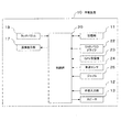
- FIG. 1 is a block diagram of an in-vehicle apparatus including a display apparatus using a touch panel according to a first embodiment of the present invention.
- the in-vehicle apparatus has a navigation function for performing route guidance and the like, and an audiovisual reproduction function for reproducing audio and video recorded on a recording medium such as a DVD (Digital Versatile Disc). It is a car navigation device.
- the on-vehicle device 10 includes a storage unit 11, an external input unit 12, a speaker 13, an image display unit 17, a touch panel 18, a control unit 20, a DVD / CD drive 22, a GPS receiver 23, a vehicle speed sensor 24, and a gyro 25. Is equipped. Further, the storage unit 11, the image display unit 17, the touch panel 18, and the control unit 20 constitute a display device.
- the DVD / CD drive 22, the GPS receiver 23, the vehicle speed sensor 24, the gyro 25, and the speaker 13 do not have to be integrally provided inside the in-vehicle apparatus 10, and are separately provided from the in-vehicle apparatus 10.
- the vehicle-mounted device 10 may be configured to be detachable from the vehicle-mounted device 10 so as to be electrically connected to the vehicle-mounted device 10 at the time of mounting.
- the storage unit 11 is a data storage device such as an HDD, an SD card, or a flash memory mounted on a printed circuit board in the in-vehicle apparatus, and may be a single type or a combination of multiple types.
- the storage unit 11 stores the icon size (the size of the icon or the display area of the icon) and the icon layout displayed on the image display unit 17 and the basic program necessary to control the operation of the in-vehicle apparatus. Furthermore, the storage unit 11 includes a program for controlling image display, application software used to execute a navigation function, or an audiovisual reproduction function, a database related to a map for navigation, a database such as a telephone number, etc. Etc., various programs and various databases are stored. Further, the storage unit 11 is provided with an area for expanding various programs, various data, etc., an area for expanding an image, and the like, as in a general storage section.
- the external input unit 12 may be a signal output from an external device connectable to the in-vehicle apparatus 10, for example, a video signal or an audio signal obtained by reproducing media such as DVD or CD, or a video signal from a digital television Input an audio signal.
- the speaker 13 is incorporated in the vehicle-mounted device 10, such as a sound effect for informing the operator that the vehicle-mounted device 10 has received an operation to the vehicle-mounted device 10, a voice input from the external device to the external input unit 12, For example, audio or music reproduced by the DVD / CD drive 22 is output.
- the image display unit 17 displays each data such as an opening screen or menu screen stored in the storage unit 11 and a video and a still image input from the external device to the external input unit 12.
- each data such as an opening screen or menu screen stored in the storage unit 11 and a video and a still image input from the external device to the external input unit 12.
- a general liquid crystal display as an example of the image display unit 17 will be described.
- the image display unit 17 includes a liquid crystal panel including a polarizing filter, a liquid crystal, a glass substrate, etc., a cold cathode tube or a component used as a light source of a liquid crystal panel such as an LED or a light guide plate, And a power supply unit for driving a liquid crystal, a light source, and an electronic component.
- the power supply unit may be provided separately from the image display unit 17.
- the touch panel 18 is a transmissive panel provided on the surface of the image display unit 17.
- the operator touches the corresponding portion of the touch panel 18 (the position of the icon displayed on the image display unit 17 in the case of icon display, an arbitrary place in the case of map display, etc.) Done by
- the control unit 20 includes a microprocessor and an electric circuit for operating the microprocessor, executes a control program stored in the storage unit 11, and performs various control processes. Further, the control unit 20 causes the image display unit 17 to display image data obtained by control processing.
- control unit 20 acquires a signal from the touch panel 18, calculates the position where the finger of the operator touches the touch panel based on this signal, and stores the information on the calculated position in the storage unit 11. Match the information assigned to the touched position of. Then, the function defined in the icon, menu, switch or the like previously associated with the touch area corresponding to the position touched by the finger of the operator is executed.
- control unit 20 reads from the storage unit 11 an image using the icon shape defined by the icon selected by the operator on the setting screen related to the icon shape setting, and causes the image display unit 17 to display the image.
- the number of microprocessors used in the control unit 20 may be one, or a plurality of microprocessors may be used for each function such as DVD reproduction and audio reproduction.
- the DVD / CD drive 22 reproduces a disc in which an audio source (or audio data) or a video source (or video data) is stored.
- the GPS receiver 23 receives signals from GPS satellites.
- the vehicle speed sensor 24 receives a vehicle speed signal from the vehicle and determines the moving speed of the vehicle.
- the gyro 25 detects the amount of rotation, the amount of change in the vertical direction, and the acceleration of the vehicle.
- the touch panel 18 is a capacitive touch panel.
- a change in electrostatic capacitance caused by the finger of the operator approaching the touch panel 18 is detected.
- the amount of change in capacitance is smaller than when operating with bare hands, so it is necessary to increase the detection sensitivity of the touch panel 18 and to increase the icon size.
- the detection sensitivity of the touch panel 18 is switched in two steps of “low detection sensitivity” and “high detection sensitivity”.
- “low” and “high” in the detection sensitivity in this case are relative high and low.
- the detection sensitivity is set relatively low for the operation with bare hands, and the detection sensitivity is set relatively high for the operation with gloves.
- the configuration itself for switching the sensitivity can be realized by applying a general technique, such as switching the setting of the threshold for the change in capacitance, and thus the details thereof will be omitted.
- the control unit 20 can detect a small change in capacitance caused by operating the touch panel 18 with a gloved finger, so the operator intended Operation becomes possible.
- the capacitance changes in a distribution close to a circle with the contact point between the finger and the touch panel as a center.
- the control unit 20 detects a change in capacitance before the finger of the operator contacts the touch panel 18, There is a possibility that a difference may occur between the position of the touch panel which the operator originally intended to touch and the position where the control unit 20 detects a change in capacitance. For this reason, it is necessary to increase the size of the icon touched by the operator to such an extent that no malfunction occurs.
- the icon size can be changed by selecting a bare hand (small icon) and a glove (large icon) before each function operation of the in-vehicle apparatus 10 is performed.
- a screen for the operator to perform icon size setting is referred to as a touch panel setting screen.
- the operator selects one corresponding to the operation situation of the operator from among the selection icons displayed on the touch panel setting screen.
- the control unit 20 controls the icon size of the operation icon (icon showing options for various function operations of the in-vehicle apparatus 10 other than the icon size setting operation) to be displayed on the image display unit 17.
- FIG. 2 is a diagram showing an example of a display screen displayed on the image display unit 17 in the present embodiment.
- FIG. 2A is a display example of the touch panel setting screen in the image display unit 17. On this screen, two icons of a bare hand (small icon) icon 101 as a first selection icon and a glove (icon large) icon 102 as a second selection icon are displayed.
- icons other than the bare hand icon 101 and the glove icon 102 which are displayed on the image display unit 17 after the setting operation on the touch panel setting screen, indicates the operation icons.
- the bare hand icon 101 is an icon selected when the operator operates the touch panel 18 with bare hand.
- the control unit 20 detects that the bare hand icon 101 is selected, the control unit 20 causes the storage unit 11 to store that “the subsequent operation is performed by the operator operating the touch panel with bare hands”.
- the icon displayed on the image display unit 17 according to various states of the in-vehicle apparatus 10 is suitable for the operator to operate the touch panel 18 with bare hand. Displayed in size and layout.
- the glove icon 102 is an icon selected when the operator operates the touch panel 18 with gloves.
- the control unit 20 detects that the glove icon 102 is selected, the control unit 20 causes the storage unit 11 to store that "the operation after the operator operates the touch panel with gloves".
- the icon size displayed on the image display unit 17 according to various states of the in-vehicle apparatus 10 allows the operator to operate the touch panel 18 with gloves. Displayed in a suitable size and layout. In this case, a larger icon is displayed than when the bare hand icon 101 is selected. However, the number of icons included in the same type of screen is the same when the bare hand icon 101 is selected and when the glove icon 102 is selected.
- FIGS. 2B and 2C show “destination setting” screens at the time of executing the navigation function as display examples of screens for various operations (other function operations of the icon size change operation) of the on-vehicle apparatus 10.
- FIG. In the “destination setting” screen nine icons are set to be displayed on the image display unit 17.
- FIG. 2B is a “destination setting” screen when the bare hand icon 101 is selected on the “touch panel setting screen”. Nine icons 110 are displayed on this screen.
- FIG. 2C shows a "destination setting" screen when the glove icon 102 is selected on the "touch panel setting screen”.
- Nine icons 111 are displayed on this screen.
- the size of the icon 111 displayed after the glove icon 102 is selected is the size of the icon 110 displayed after the bare hand icon 101 is selected. It is displayed larger than.
- control unit 20 can reliably detect the icon that the operator has tried to touch.
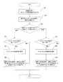
- control unit 20 executes the touch panel setting function (program) stored in the storage unit 11 when detecting that the operator has selected the touch panel setting function by a predetermined operation such as turning on the power of the in-vehicle device 10. Do it (start).
- control unit 20 causes the image display unit 17 to display a touch panel setting screen for the operator to select an icon size (step S1).
- the operator operates the touch panel 18. Specifically, the operator selects either the bare hand icon 101 or the glove icon 102 and touches the selected icon with a finger. Thereby, the control unit 20 detects that the change of the electrostatic capacitance detection value becomes larger than the threshold value by this operation (step S2).
- the control unit 20 calculates the coordinates of the touch panel 18 touched by the finger of the operator, and determines whether the icon selected by the operator is the bare hand icon 101 or the glove icon 102 based on the coordinates ((1) Step S3)
- step S3 When the control unit 20 determines that the bare hand icon 101 on the touch panel setting screen is selected by the operator in step S3 (step S3: "naked hand"), the sensitivity of the touch panel at that time is set low or high. It is determined whether there is any (step S4).
- step S4 when the sensitivity of the touch panel at that time is set high (step S4: "high"), the control unit 20 sets the sensitivity of the panel low (step S5).
- step S5 After the sensitivity of the panel is set low in step S5, or when the sensitivity of the touch panel is set low in step S4 (step S4: "low"), the control unit 20 selects a bare hand icon on the touch panel setting screen. It is stored in the storage unit 11 that 101 is selected. In addition, the control unit 20 reads the display screen of the icon size allocated to the selected setting (a display screen including a relatively small icon size icon as the first display screen), and displays the image as the subsequent operation screen. It is set to be displayed on the unit 17 (step S6), and the processing of the touch panel setting function is ended.
- the display screen of the icon size allocated to the selected setting a display screen including a relatively small icon size icon as the first display screen
- control unit 20 determines in step S3 that the glove icon 102 on the touch panel setting screen is selected by the operator (step S3: “gloves"), the sensitivity of the touch panel at that time is set low or high. It is determined whether or not there is (step S7).
- step S7 when the sensitivity of the touch panel is set low at that time (step S7: "low"), the control unit 20 sets the panel sensitivity high (step S8).
- step S8 After the panel sensitivity is set high in step S8, or when the touch panel sensitivity is set high in step S7 (step S7: "high"), the control unit 20 displays a glove icon on the touch panel setting screen. The fact that 102 has been selected is stored in the storage unit 11. In addition, the control unit 20 reads the display screen of the icon size allocated to the selected setting (display screen including a relatively large icon size icon as the second display screen), and displays the image as the subsequent operation screen. The setting is made to display on the unit 17 (step S9), and the processing of the touch panel setting function is ended.
- control unit 20 causes the storage unit 11 to store the operation situation of the operator corresponding to the selected icon (the bare hand icon 101 or the glove icon 102) selected by the operator on the touch panel setting screen. Thereafter, when an operation icon such as destination setting is displayed on the image display unit 17 by the operation of the operator, the control unit 20 reads the operation situation of the operator from the storage device 11, and displays the icon size corresponding to the situation. An operation screen including an operation icon is displayed on the image display unit 17.
- control unit 20 stores the option (the bare hand icon 101 or the glove icon 102) selected by the operator on the touch panel setting screen in the storage unit, and then the control unit 20 causes the image display unit 17 to operate by the operation manual.
- the control unit 20 reads out from the storage device 11 the option selected by the operator on the touch panel setting screen, and defines the icon size and display position allocated to the option.
- the display screen used to operate each function (other functions) of the on-vehicle apparatus other than the setting function using “” is displayed on the image display unit 17.
- the icon size, the display position, and the like of the above-described operation icon are stored on the data table of the storage unit 11.
- two icon sizes are selected when the bare hand icon 101 is selected on the touch panel setting screen and when the glove icon 102 is selected. Are stored corresponding to the bare hand icon 101 and the glove icon 102, respectively.
- the image display unit 17 of the in-vehicle apparatus 10 is often in a horizontally long shape, in the present embodiment, the image display unit 17 is described as being horizontally long.
- the icon size that the operator can easily touch is an icon that is large in size in the vertical and horizontal directions with respect to the contact surface of the finger that contacts the touch panel 18 in both vertical and horizontal directions.
- the length of the image display unit 17 in the horizontal direction is the width of the area required when the operator's finger operates the touch panel
- the horizontal length of the icon displayed on the image display unit 17 is also sufficiently long with respect to the horizontal length of the area required when the operator's finger operates the touch panel.
- the length of the image display unit 17 in the vertical direction is the vertical direction of the area required when the operator's finger operates the touch panel.
- the icon shape is often not long enough, in addition to a sufficient length.
- the control unit 20 detects that the operator operated the touch panel with a gloved finger To do this, it is necessary to increase the detection sensitivity and also to detect small capacitance changes.
- the ratio of the vertical length of the icon to the horizontal length of the icon is desirable to be equal to or close to 1 become.
- the shorter one of the vertical length of the icon and the horizontal length of the icon (hereinafter referred to as “short side”) is longer in the case of wearing gloves than in the case of bare hands.
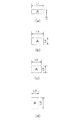
- FIG. 4 is a diagram for explaining the icon size.
- FIG. 4A shows an example of the icon size at the time of the bare hand operation (after the bare hand icon 101 is selected), and is referred to as icon example 1.
- the horizontal length of the icon example 1 is L1
- the vertical length of the icon example 1 is L2.
- the icon example 1 is added that the image display unit 17 of the in-vehicle apparatus 10 is horizontally long, so the horizontal length L1 is set longer than the vertical length L2.
- Example Icon 1 when the color of the icon itself and other colors (such as background color) on the display screen are similar colors, the icon size shown in Example Icon 1 that is easy to identify individual icons as described above is useful. .
- the size of the icon shown in Example Icon 1 can be said to be a size suitable for the operator to operate the touch panel 18 with bare hands, and the layout in which the icons shown in Example Icon 1 are arranged is a case where the operator bare hands Can be said to be a layout suitable for operating the touch panel 18.
- FIG. 4B is a view showing an icon example 2 larger than the icon example 1; the horizontal length (long side) L3 of the icon example 2 is the horizontal length (long side) L1 of the icon example 1 equal.
- the vertical length (short side) L4 of the icon example 2 is longer than the vertical length (short side) L2 of the icon example 1.
- the short side is L4> L2.
- the ratio of L3 to L4 is closer to 1 than the ratio of L1 to L2, and the short side L4 of the icon example 2 is longer than the short side L2 of the icon example 1.
- FIG. 4C is a view showing an example icon 3 larger than the example icon 1, and the long side L5 of the example icon 3 is shorter than the long side L1 of the example icon 1, but the short side L6 of the example icon 3 is an icon Longer than the short side L2 of Example 1.
- the long side is L5 ⁇ L1
- the short side is L6> L2.
- the ratio of L5 to L6 is closer to 1 than the ratio of L1 to L2, and the short side L6 of the icon example 3 is longer than the short side L2 of the icon example 1.
- the horizontal length L3 is set longer than the vertical length L4.
- the horizontal length L5 of the icon shown in Example Icon 3 is set longer than the vertical length L6.
- the ratio of lengths of L3 and L4 of the icon example 2 is closer to “1” than the ratio of lengths of L1 and L2 of the icon example 1.
- the ratio of lengths of L5 and L6 of the icon example 3 is closer to “1” than the ratio of lengths of L1 and L2 of the icon example 1.
- the sizes of the icons shown in Example 2 and Example 3 can be said to be suitable for the operator to operate the touch panel 18 with gloves, and the icons shown in Example 2 and 3 are examples.
- the arranged layout can be said to be a layout suitable for the operator to operate the touch panel 18 with gloves.
- FIG. 4D is a view showing an icon example 4 larger than the icon example 1.
- the vertical side is the short side, but in the icon example 4, the horizontal side is the short side.
- the long side length L8 of the icon example 4 is shorter than the long side length L1 of the icon example 1.
- the short side length L7 of the icon example 4 is longer than the short side length L2 of the icon example 1.
- the ratio of L8 to L7 is closer to 1 than the ratio of L1 to L2, and the short side L7 of the icon example 4 is longer than the short side L2 of the icon example 1.
- the icon shown in the icon example 4 is considered to be used in the case of using the above-described in-vehicle device 10 by rotating it 90 degrees to the left or right, that is, in the vertically long state. That is, in this case, it is considered that the in-vehicle apparatus 10 is an apparatus which can be used in both the horizontally long state and the vertically long state.
- the icon shown in this icon example 4 can secure a sufficient area for detecting an operation from the operator as in the icon example 2 and the icon example 3.
- the touch panel with a gloved finger is used as described above.
- the detection sensitivity can be increased to appropriately cope with the detection of a small change in capacitance.
- the operator when the device to be applied (in-vehicle device 10 in the present embodiment) is used in the vertically long state, the operator operates the touch panel 18 with gloves when the size of the icon shown in the icon example 4 is used. It can be said that the size is suitable for.
- the layout in which the icons shown in the icon example 4 are arranged can be said to be a layout suitable for the operator to operate the touch panel 18 with gloves when the applied device is used in the vertically long state. .
- icon example 2 to icon example 4 larger than icon example 1 are shown in FIG. 4, the ratio of the vertical length of the icon to the horizontal length of the icon is equal or from icon example 1 As long as it is close to 1 and the short side of the icon is larger than the short side L2 of the icon example 1, an aspect ratio other than the illustrated shape may be used.
- a large icon suitable for the aspect ratio of the display unit and the number of icons to be displayed at one time can be defined and stored in the storage unit 11.
- the case where the operation icon is rectangular has been described. That is, the display area of the operation icon is described as being composed of two long sides and two short sides forming a rectangle.
- the shape (display area) of the operation icon may not have four corners like a rectangle, and may be an oval shape or a long hole shape.
- the icon size may be set as described above.
- the ratio of the vertical length to the horizontal length of the glove attachment icon is equal to or closer to 1 than the bare hand icon, and for the glove attachment It stores icon display screen data in which an icon whose size is such that the short side of the icon is longer than the short side of the bare hand icon is displayed.
- the operator can set a display screen using an icon size suitable for operation in touch panel setting in accordance with bare hand or glove wearing.
- the present invention is not limited to this, and three or more options may be used.
- the selection icon and the operation icon are displayed larger to increase the detection sensitivity.
- the icon size corresponding to the thickness and material of a plurality of gloves can be set, and the convenience of the operator is enhanced.
- the on-vehicle navigation device as the display device having the touch panel
- the on-vehicle navigation device including the display device using the touch panel is simply described. Description will be made as "in-vehicle device”.
- the display device including the touch panel in the second embodiment performs the same configuration and operation processing as the first embodiment, and thus the detailed description thereof is omitted.
- a display device provided with a conventional touch panel
- the user can operate the touch panel in order to select the size of an icon to be displayed on the touch panel from among a plurality of icon sizes stored in the storage unit.
- a capacitance distribution detection unit is required to detect the capacitance distribution, and a large number of control lines and detection electrodes are required to detect the capacitance distribution, resulting in a complicated structure.
- the icon size can be changed by selecting the bare hands (small icon) and gloves (large icon) when operating the in-vehicle apparatus 10 for the first time before each function operation of the in-vehicle apparatus 10 is performed. I have to. Also, the icon size selected when the in-vehicle apparatus 10 is operated for the first time is stored, and the stored icon size is used in daily operation. By this, the icon setting can be performed only when the operator uses the in-vehicle apparatus 10 for the first time or when the operator intends, and the icon size suitable for the operator can be displayed without performing the icon setting thereafter. . Therefore, the operator does not have to perform troublesome operations.
- a button may be provided to shift to the operation processing of the in-vehicle apparatus 10 in step S1 of the processing flow shown in FIG.
- This button is realized by displaying a dedicated icon on the image display unit 17 for a short time immediately after the power of the in-vehicle apparatus 10 is turned on or providing the in-vehicle apparatus 10 with a dedicated hard key such as a mechanical switch. Can.
- the present invention can be provided with a simple configuration without the need to detect the capacitance distribution.
- the in-vehicle apparatus causes the storage device to store an appropriate icon size according to the condition of the operator when used for the first time, and then the operator takes over gloves or
- the icon size can be set according to the usage condition only when the operator has intended it. This makes it possible to display an easy-to-operate icon and to easily perform the operation intended by the operator without setting the icon size each time in subsequent use. In addition, it is possible to realize a device that does not impair the operability with a simple configuration.
- the on-vehicle apparatus is provided with an image display unit displaying an operation icon for operating the own apparatus, and an electrostatic capacity type provided on the front surface of the image display unit to detect a change in electrostatic capacity.
- a touch panel a control unit for causing the image display unit to display the first selection icon and the second selection icon, and a storage device for storing which one of the first selection icon and the second selection icon is selected
- the control unit calls the storage unit which of the first selection icon and the second selection icon is selected from the storage unit, and displays the operation icon associated with the selected selection icon on the image display unit.
- the selected icon selected by the operator and the size of the operation icon associated with the selected icon are stored, and the operation icon of the size associated with the selected icon selected by the operator is displayed on the image display unit It can be displayed.
- This allows the operator to reliably select the icon intended by the operator, whether wearing bare hands or wearing gloves.
- it is possible to realize a device that does not impair operability with a simple configuration.
- by selecting the selection icon only when the operator intends it is possible to display the icon size suitable for the use situation of the operator without performing the icon size setting when using it thereafter. There is no need for troublesome operations.
- the following description exemplifies an on-vehicle navigation device as a display device provided with a touch panel. Therefore, the on-vehicle navigation device including the display device using the touch panel is simply described. Description will be made as "in-vehicle device”.
- the third embodiment shows an example of icon display of the image display unit 17 (an example of display of a “facility search” screen at the time of executing the navigation function) by the function operation other than the icon size changing operation different from the first embodiment.
- FIG. 5 is a diagram for explaining the operation of the in-vehicle apparatus according to the present embodiment.
- FIG. 5 (a) is common to FIG. 2 (a).
- FIGS. 5B and 5C show an example of the “facility search” screen at the time of executing the navigation function as an example of image display by various operations of the in-vehicle apparatus 10 (other function operations of the icon size change operation).
- FIG. In the "facility search” screen 12 icons are set to be displayed.
- FIG. 5B is a view showing an example of the “facility search” screen after selecting the bare hand icon 101 on the “touch panel setting screen”. Twelve icons 112 are displayed on this screen.
- FIG. 5C is a diagram showing an example of the “facility search” screen after selecting the glove icon 102 on the “touch panel setting screen”. Twelve icons 113 are displayed on this screen.
- the size of the icon 113 displayed after the glove icon 102 is selected is the size of the icon 112 displayed after the bare hand icon 101 is selected. It is displayed larger than.
- the bare hand icon 101 is selected in the "touch panel setting"
- the ratio of the long side to the short side of the icon after being displayed approaches 1 and the short side of the icon is the icon after selecting the bare hand icon 101 in "touch panel setting" Longer than the short side of
- operation icons after bare hand icon 101 is selected are disposed at m 1 row n 1 column on the display screen, a display screen of the glove icon 102 is selected for the operation this same function
- the operation icons after being placed are arranged in m 2 rows and n 2 columns on the display screen, and are respectively displayed on the image display unit 17 (m and n are natural numbers).
- the icon 112 is displayed in four rows and three columns in the example shown in FIG. 5B, since the image display unit 17 of the in-vehicle apparatus 10 is horizontally long, the bare hand is not displayed in the example shown in FIG. Although the long side becomes shorter than the icon 112 displayed after the icon is selected, the facility search screen is displayed in which the icons 113 larger than the icon 112 are designed in three rows and four columns, which are designed to have short sides.
- 12 icons can be displayed at one time as in the case of the icon displayed after selecting the bare hand icon 101 in the “touch panel setting”. it can.
- the ratio of the vertical length to the horizontal length of the glove wearing icon is equal to or closer to 1 than the bare hand icon, and the glove wearing icon An icon whose size is shorter than the short side of the bare hand icon is displayed, and icon display screen data designed to keep the number of icons displayed at one time is stored.
- icon display screen data designed to keep the number of icons displayed at one time is stored.
- the display screen can be displayed on the image display unit and the control unit can generate a capacitance change sufficient to recognize the operation of the operator, the operation intended by the operator can be reliably performed.
- the operator wearing the gloves can operate reliably while securing the amount of information that can be displayed on the screen without significantly reducing the design of the screen display. can do.
- the number of rows and the number of columns of the icon display may be other than four rows and three columns.
- the optimum icon size and icon layout can be set according to the number of icons displayed at one time.
- the number of icons displayed on one screen is six, it may be three rows and two columns, and when the number of icons displayed on one screen is twenty, it may be five rows and four columns.
- the layout of the icons displayed on the image display unit 17 may be arbitrary when a large icon size is selected. In this case, movement of the frequently used icons can be reduced and the burden on the operator can be reduced. .
- the most frequently used icon may always be displayed at the lower right, etc., and in this case as well, the operator's burden is reduced because the location where the frequently used icon is displayed is known in advance. Can.
- an image display part may be vertically long.
- the present invention can also be applied to a device having a vertically long display unit such as a mobile device.
- the display device using the touch panel according to the present invention can display an icon display screen suitable for operation with a gloved hand, and is useful for a display device using the touch panel, such as a navigation device or an in-vehicle display
- the present invention can be applied to in-vehicle devices, mobile devices, and the like.
Abstract
Description
以下、本発明の実施の形態1におけるタッチパネルを備えた表示装置について、図面を用いて説明する。 Embodiment 1
Hereinafter, a display device provided with the touch panel in Embodiment 1 of the present invention will be described using the drawings.
以下、本発明の実施の形態2におけるタッチパネルを備えた表示装置について、図面を用いて説明する。 Second Embodiment
Hereinafter, a display device provided with the touch panel in
以下、本発明の実施の形態3におけるタッチパネルを備えた表示装置について、図面を用いて説明する。 Third Embodiment
Hereinafter, a display device provided with the touch panel in the third embodiment of the present invention will be described using the drawings.
11 記憶部
12 外部入力部
13 スピーカ
17 画像表示部
18 タッチパネル
20 制御部
22 DVD/CDドライブ
23 GPS受信機
24 車速センサ
25 ジャイロ
101 素手(アイコン小)アイコン
102 手袋(アイコン大)アイコン
110 素手操作時のアイコン表示例
111 手袋操作時のアイコン表示例
112 素手操作時のアイコン表示例
113 手袋操作時のアイコン表示例
DESCRIPTION OF SYMBOLS 10 Vehicle-mounted
Claims (8)
- データを表示する画像表示部と、
前記画像表示部の表面に設けられるタッチパネルと、
前記画像表示部に表示させる画像を記憶する記憶部と、
前記タッチパネルの操作者に触られた領域を検出し、検出結果に基づいて前記記憶部から画像を読み出して前記画像表示部に表示させる制御部と、を備え、
前記記憶部は、
前記操作者の操作状況を示す選択アイコンと、操作の選択肢を示す操作アイコンと、を対応付けて記憶し、
前記操作アイコンの大きさは、選択アイコン毎に異なり、
前記制御部は、
複数の前記選択アイコンを前記画像表示部に表示させ、
前記操作者によって選択された選択アイコンに対応付けられた大きさの操作アイコンを前記画像表示部に表示させる、
表示装置。 An image display unit for displaying data;
A touch panel provided on the surface of the image display unit;
A storage unit for storing an image to be displayed on the image display unit;
A control unit configured to detect a region touched by the touch panel operator, read an image from the storage unit based on the detection result, and display the image on the image display unit;
The storage unit is
Storing a selection icon indicating an operation situation of the operator and an operation icon indicating a choice of operation in association with each other;
The size of the operation icon is different for each selected icon,
The control unit
Displaying a plurality of the selection icons on the image display unit;
Displaying on the image display unit an operation icon of a size associated with the selected icon selected by the operator;
Display device. - 前記記憶部は、直近に選択された前記選択アイコンを記憶し、
前記制御部は、前記操作者から前記選択アイコンを前記画像表示部に表示させる指示を受けるまでは、前記記憶部に記憶された選択アイコンに対応付けられた大きさの操作アイコンを前記画像表示部に表示させる、請求項1記載の表示装置。 The storage unit stores the selected icon most recently selected,
The control unit is configured to display an operation icon having a size corresponding to the selected icon stored in the storage unit until the control unit receives an instruction to display the selected icon on the image display unit from the operator. The display apparatus according to claim 1, wherein the display apparatus displays the information. - 前記制御部は、前記各選択アイコンの大きさを互いに異ならせて前記画像表示部に表示させ、大きい選択アイコンほど前記タッチパネルの検出感度を高く設定する、請求項1記載の表示装置。 2. The display device according to claim 1, wherein the control unit causes the image display unit to display different sizes of the selection icons and sets detection sensitivity of the touch panel to be higher as the selection icons are larger.
- 前記記憶部は、前記各選択アイコンに対応付けられ前記操作アイコンが含まれる複数の表示画面を記憶し、
前記各表示画面における前記操作アイコンの表示領域は互いに異なるように設定され、
前記制御部は、選択された選択アイコンに対応付けられた表示画面を前記画像表示部に表示する、請求項1記載の表示装置。 The storage unit stores a plurality of display screens associated with the respective selection icons and including the operation icons.
The display areas of the operation icons on the display screens are set to be different from each other,
The display device according to claim 1, wherein the control unit displays a display screen associated with the selected selection icon on the image display unit. - 前記制御部は、所定の操作を検出した場合に前記選択アイコンを前記画像表示部に表示する、請求項2記載の表示装置。 The display device according to claim 2, wherein the control unit displays the selection icon on the image display unit when a predetermined operation is detected.
- 前記画像表示部に前記選択アイコンを表示するためのボタンを備える、請求項2記載の表示装置。 The display device according to claim 2, further comprising a button for displaying the selection icon on the image display unit.
- 前記操作アイコンの表示領域は長方形であり、
前記制御部は、
前記各選択アイコンの大きさを互いに異ならせて前記画像表示部に表示させ、
大きい選択アイコンに対応付けられた前記操作アイコンの長辺と短辺との比は、小さい選択アイコンに対応付けられた前記操作アイコンの長辺と短辺との比よりも1に近い、請求項1記載の表示装置。 The display area of the operation icon is rectangular,
The control unit
Displaying the sizes of the selection icons on the image display unit with different sizes from each other,
The ratio of the long side to the short side of the operation icon associated with the large selection icon is closer to 1 than the ratio of the long side to the short side of the operation icon associated with the small selection icon. The display device according to 1. - 前記操作アイコンが含まれる各表示画面には複数かつ互いに同数の操作アイコンが含まれ、前記各表示画面において操作アイコンはm行n列に配置され(m、nは自然数)、前記mと前記nとの積が前記全ての表示画面において等しい、請求項1記載の表示装置。
A plurality of and the same number of operation icons are included in each display screen including the operation icon, and the operation icons are arranged in m rows and n columns in each display screen (m and n are natural numbers), and m and n The display device according to claim 1, wherein the product of and is equal on all the display screens.
Priority Applications (4)
| Application Number | Priority Date | Filing Date | Title |
|---|---|---|---|
| EP11768632.9A EP2560076A4 (en) | 2010-04-13 | 2011-04-13 | Display device |
| US13/639,925 US20130038556A1 (en) | 2010-04-13 | 2011-04-13 | Display apparatus |
| JP2012510575A JP5720003B2 (en) | 2010-04-13 | 2011-04-13 | Display device |
| CN201180018988.9A CN102859325B (en) | 2010-04-13 | 2011-04-13 | Display device |
Applications Claiming Priority (4)
| Application Number | Priority Date | Filing Date | Title |
|---|---|---|---|
| JP2010-091888 | 2010-04-13 | ||
| JP2010091888 | 2010-04-13 | ||
| JP2010-116871 | 2010-05-21 | ||
| JP2010116871 | 2010-05-21 |
Publications (1)
| Publication Number | Publication Date |
|---|---|
| WO2011129109A1 true WO2011129109A1 (en) | 2011-10-20 |
Family
ID=44798492
Family Applications (1)
| Application Number | Title | Priority Date | Filing Date |
|---|---|---|---|
| PCT/JP2011/002180 WO2011129109A1 (en) | 2010-04-13 | 2011-04-13 | Display device |
Country Status (5)
| Country | Link |
|---|---|
| US (1) | US20130038556A1 (en) |
| EP (1) | EP2560076A4 (en) |
| JP (1) | JP5720003B2 (en) |
| CN (1) | CN102859325B (en) |
| WO (1) | WO2011129109A1 (en) |
Cited By (6)
| Publication number | Priority date | Publication date | Assignee | Title |
|---|---|---|---|---|
| WO2013094624A1 (en) * | 2011-12-19 | 2013-06-27 | Necカシオモバイルコミュニケーションズ株式会社 | Information processing device |
| WO2014004805A1 (en) * | 2012-06-28 | 2014-01-03 | Synaptics Incorporated | Systems and methods for switching sensing regimes for gloved and ungloved user input |
| EP2720120A1 (en) * | 2011-06-10 | 2014-04-16 | NEC CASIO Mobile Communications, Ltd. | Input device and method for controlling touch panel |
| EP2810144B1 (en) * | 2012-02-02 | 2017-03-22 | Sony Mobile Communications, Inc | Portable electronic device and method for controlling a portable electronic device having a proximity-sensing user interface |
| US9817517B2 (en) | 2014-10-22 | 2017-11-14 | Hyundai Motor Company | Touch device and method of controlling the same that changes the sensitivity of a touch input based on the touch input's capacitance |
| JP2018092497A (en) * | 2016-12-07 | 2018-06-14 | 三菱自動車工業株式会社 | Operation displaying apparatus |
Families Citing this family (8)
| Publication number | Priority date | Publication date | Assignee | Title |
|---|---|---|---|---|
| KR20140106097A (en) * | 2013-02-25 | 2014-09-03 | 삼성전자주식회사 | Method and apparatus for determining touch input object in an electronic device |
| JP6236640B2 (en) * | 2013-07-24 | 2017-11-29 | パナソニックIpマネジメント株式会社 | Detection method using capacitance type sensor and electronic device |
| US9189114B2 (en) * | 2013-07-24 | 2015-11-17 | Synaptics Incorporated | Face detection with transcapacitive sensing |
| US10101844B2 (en) * | 2014-03-14 | 2018-10-16 | Lg Electronics Inc. | Mobile terminal and method of controlling the same based on type of touch object used to apply touch input |
| KR101539330B1 (en) * | 2014-04-30 | 2015-07-30 | 엘지디스플레이 주식회사 | Display Panel For Display Device |
| CA2957179A1 (en) * | 2014-08-19 | 2016-02-25 | Touchsensor Technologies, Llc | Capacitive sensor filtering apparatus, method, and system |
| JP6256497B2 (en) * | 2016-03-04 | 2018-01-10 | 日本電気株式会社 | Information processing system, information processing apparatus, control method, and program |
| US10409413B2 (en) * | 2016-10-27 | 2019-09-10 | Motorola Solutions, Inc. | Apparatus and method for expanded touch sensitive actuation of a user interface button |
Citations (5)
| Publication number | Priority date | Publication date | Assignee | Title |
|---|---|---|---|---|
| JP2003271310A (en) * | 2002-03-13 | 2003-09-26 | Canon Inc | Information inputting and outputting device, method for controlling the device, and program for realizing the method |
| JP2005050265A (en) * | 2003-07-31 | 2005-02-24 | Sato Corp | Touch screen device |
| JP2008217704A (en) | 2007-03-07 | 2008-09-18 | Nec Corp | Display device and portable information equipment |
| JP2010091888A (en) | 2008-10-10 | 2010-04-22 | Kyocera Mita Corp | Toner container and image forming apparatus including the same |
| JP2010116871A (en) | 2008-11-13 | 2010-05-27 | Mitsubishi Motors Corp | Idle stop start system |
Family Cites Families (11)
| Publication number | Priority date | Publication date | Assignee | Title |
|---|---|---|---|---|
| JPH1091226A (en) * | 1996-09-11 | 1998-04-10 | Fanuc Ltd | Machine control device |
| JP2007027034A (en) * | 2005-07-21 | 2007-02-01 | Calsonic Kansei Corp | Electrostatic capacity type touch switch |
| JP4476945B2 (en) * | 2006-02-24 | 2010-06-09 | 京セラミタ株式会社 | Image forming apparatus |
| KR100881186B1 (en) * | 2007-01-04 | 2009-02-05 | 삼성전자주식회사 | Touch screen display device |
| US20080167081A1 (en) * | 2007-01-10 | 2008-07-10 | Eng U P Peter | Keyless touch-screen cellular telephone |
| JP2008243128A (en) * | 2007-03-29 | 2008-10-09 | Sanyo Electric Co Ltd | Touch panel device |
| KR101405928B1 (en) * | 2007-06-07 | 2014-06-12 | 엘지전자 주식회사 | A method for generating key signal in mobile terminal and the mobile terminal |
| JP2009004999A (en) * | 2007-06-20 | 2009-01-08 | Panasonic Corp | Video data management device |
| KR20100000514A (en) * | 2008-06-25 | 2010-01-06 | 엘지전자 주식회사 | Image display device with touch screen and method of controlling the same |
| US20100277420A1 (en) * | 2009-04-30 | 2010-11-04 | Motorola, Inc. | Hand Held Electronic Device and Method of Performing a Dual Sided Gesture |
| US8766926B2 (en) * | 2009-10-14 | 2014-07-01 | Blackberry Limited | Touch-sensitive display and method of controlling same |
-
2011
- 2011-04-13 CN CN201180018988.9A patent/CN102859325B/en active Active
- 2011-04-13 US US13/639,925 patent/US20130038556A1/en not_active Abandoned
- 2011-04-13 EP EP11768632.9A patent/EP2560076A4/en not_active Ceased
- 2011-04-13 JP JP2012510575A patent/JP5720003B2/en not_active Expired - Fee Related
- 2011-04-13 WO PCT/JP2011/002180 patent/WO2011129109A1/en active Application Filing
Patent Citations (5)
| Publication number | Priority date | Publication date | Assignee | Title |
|---|---|---|---|---|
| JP2003271310A (en) * | 2002-03-13 | 2003-09-26 | Canon Inc | Information inputting and outputting device, method for controlling the device, and program for realizing the method |
| JP2005050265A (en) * | 2003-07-31 | 2005-02-24 | Sato Corp | Touch screen device |
| JP2008217704A (en) | 2007-03-07 | 2008-09-18 | Nec Corp | Display device and portable information equipment |
| JP2010091888A (en) | 2008-10-10 | 2010-04-22 | Kyocera Mita Corp | Toner container and image forming apparatus including the same |
| JP2010116871A (en) | 2008-11-13 | 2010-05-27 | Mitsubishi Motors Corp | Idle stop start system |
Non-Patent Citations (1)
| Title |
|---|
| See also references of EP2560076A4 |
Cited By (10)
| Publication number | Priority date | Publication date | Assignee | Title |
|---|---|---|---|---|
| EP2720120A1 (en) * | 2011-06-10 | 2014-04-16 | NEC CASIO Mobile Communications, Ltd. | Input device and method for controlling touch panel |
| EP2720120A4 (en) * | 2011-06-10 | 2014-12-17 | Nec Casio Mobile Comm Ltd | Input device and method for controlling touch panel |
| WO2013094624A1 (en) * | 2011-12-19 | 2013-06-27 | Necカシオモバイルコミュニケーションズ株式会社 | Information processing device |
| JPWO2013094624A1 (en) * | 2011-12-19 | 2015-04-27 | Necカシオモバイルコミュニケーションズ株式会社 | Information processing device |
| US9594446B2 (en) | 2011-12-19 | 2017-03-14 | Nec Corporation | Information processing device that determines operational mode based on user's touch |
| JP2017134849A (en) * | 2011-12-19 | 2017-08-03 | 日本電気株式会社 | Information processing device |
| EP2810144B1 (en) * | 2012-02-02 | 2017-03-22 | Sony Mobile Communications, Inc | Portable electronic device and method for controlling a portable electronic device having a proximity-sensing user interface |
| WO2014004805A1 (en) * | 2012-06-28 | 2014-01-03 | Synaptics Incorporated | Systems and methods for switching sensing regimes for gloved and ungloved user input |
| US9817517B2 (en) | 2014-10-22 | 2017-11-14 | Hyundai Motor Company | Touch device and method of controlling the same that changes the sensitivity of a touch input based on the touch input's capacitance |
| JP2018092497A (en) * | 2016-12-07 | 2018-06-14 | 三菱自動車工業株式会社 | Operation displaying apparatus |
Also Published As
| Publication number | Publication date |
|---|---|
| JPWO2011129109A1 (en) | 2013-07-11 |
| EP2560076A1 (en) | 2013-02-20 |
| US20130038556A1 (en) | 2013-02-14 |
| EP2560076A4 (en) | 2013-06-05 |
| CN102859325B (en) | 2016-09-14 |
| JP5720003B2 (en) | 2015-05-20 |
| CN102859325A (en) | 2013-01-02 |
Similar Documents
| Publication | Publication Date | Title |
|---|---|---|
| WO2011129109A1 (en) | Display device | |
| US8570290B2 (en) | Image display device | |
| JP5431473B2 (en) | Information display device | |
| US9377946B2 (en) | On-board apparatus | |
| KR101675188B1 (en) | Operating method for a display device of a vehicle | |
| US10449857B2 (en) | Information reproduction system for a vehicle and method for providing information for the user of a vehicle | |
| US20150015521A1 (en) | Gesture input operation processing device | |
| US20160077652A1 (en) | Vehicle, display device for vehicle, and method for controlling the vehicle display device | |
| JP2012198740A (en) | Touch panel and display device including touch panel | |
| US10967737B2 (en) | Input device for vehicle and input method | |
| WO2017111075A1 (en) | On-board device, display area dividing method, program, and information control device | |
| WO2017169263A1 (en) | Display processing device and display processing program | |
| KR101648029B1 (en) | An touch screen displaying apparatus, a vehicle which the touch screen displaying apparatus installed in and a method of controlling the touch screen displaying apparatus | |
| JP4548325B2 (en) | In-vehicle display device | |
| JP6177660B2 (en) | Input device | |
| JP2006001498A (en) | On-vehicle unit device and operation method by touch panel | |
| JP4526307B2 (en) | Function selection device | |
| JP2019049738A (en) | Display control device | |
| JP2019028570A (en) | Display controller, display system, display control method and program | |
| JP5666678B2 (en) | Information display device | |
| JP2015014860A (en) | Information processing device |
Legal Events
| Date | Code | Title | Description |
|---|---|---|---|
| WWE | Wipo information: entry into national phase |
Ref document number: 201180018988.9 Country of ref document: CN |
|
| 121 | Ep: the epo has been informed by wipo that ep was designated in this application |
Ref document number: 11768632 Country of ref document: EP Kind code of ref document: A1 |
|
| WWE | Wipo information: entry into national phase |
Ref document number: 2012510575 Country of ref document: JP |
|
| WWE | Wipo information: entry into national phase |
Ref document number: 13639925 Country of ref document: US |
|
| WWE | Wipo information: entry into national phase |
Ref document number: 2011768632 Country of ref document: EP |
|
| NENP | Non-entry into the national phase |
Ref country code: DE |