WO2011129098A1 - 通信ノード及びネットワークノード - Google Patents
通信ノード及びネットワークノード Download PDFInfo
- Publication number
- WO2011129098A1 WO2011129098A1 PCT/JP2011/002154 JP2011002154W WO2011129098A1 WO 2011129098 A1 WO2011129098 A1 WO 2011129098A1 JP 2011002154 W JP2011002154 W JP 2011002154W WO 2011129098 A1 WO2011129098 A1 WO 2011129098A1
- Authority
- WO
- WIPO (PCT)
- Prior art keywords
- message
- mtc
- event
- mtc device
- information
- Prior art date
Links
- 238000004891 communication Methods 0.000 title claims abstract description 292
- 230000005540 biological transmission Effects 0.000 claims abstract description 229
- 238000000034 method Methods 0.000 claims abstract description 82
- 230000007704 transition Effects 0.000 claims description 43
- 230000004044 response Effects 0.000 claims description 40
- 230000008859 change Effects 0.000 claims description 35
- 230000002441 reversible effect Effects 0.000 abstract description 236
- 239000000779 smoke Substances 0.000 abstract description 139
- 238000001514 detection method Methods 0.000 abstract description 28
- 238000012545 processing Methods 0.000 description 128
- 230000006870 function Effects 0.000 description 97
- 238000012546 transfer Methods 0.000 description 36
- 238000007726 management method Methods 0.000 description 24
- 230000008569 process Effects 0.000 description 20
- 230000009471 action Effects 0.000 description 15
- 230000003111 delayed effect Effects 0.000 description 13
- 238000010586 diagram Methods 0.000 description 12
- 230000004048 modification Effects 0.000 description 12
- 238000012986 modification Methods 0.000 description 12
- 230000002829 reductive effect Effects 0.000 description 12
- 239000000284 extract Substances 0.000 description 9
- 230000001629 suppression Effects 0.000 description 9
- 238000012790 confirmation Methods 0.000 description 8
- 230000000694 effects Effects 0.000 description 8
- 238000005516 engineering process Methods 0.000 description 8
- XLYOFNOQVPJJNP-UHFFFAOYSA-N water Substances O XLYOFNOQVPJJNP-UHFFFAOYSA-N 0.000 description 6
- 238000007796 conventional method Methods 0.000 description 5
- 230000003068 static effect Effects 0.000 description 5
- 238000003860 storage Methods 0.000 description 5
- 230000001133 acceleration Effects 0.000 description 4
- 238000012423 maintenance Methods 0.000 description 4
- 230000011664 signaling Effects 0.000 description 4
- 101100435066 Caenorhabditis elegans apn-1 gene Proteins 0.000 description 3
- 238000013523 data management Methods 0.000 description 3
- 230000010354 integration Effects 0.000 description 3
- 230000014759 maintenance of location Effects 0.000 description 3
- 238000012544 monitoring process Methods 0.000 description 3
- 230000001960 triggered effect Effects 0.000 description 3
- 230000008901 benefit Effects 0.000 description 2
- 239000003795 chemical substances by application Substances 0.000 description 2
- 230000001934 delay Effects 0.000 description 2
- 238000009826 distribution Methods 0.000 description 2
- 230000000670 limiting effect Effects 0.000 description 2
- 238000004519 manufacturing process Methods 0.000 description 2
- 238000004705 quadratic configuration interaction calculation Methods 0.000 description 2
- 230000009467 reduction Effects 0.000 description 2
- 230000000717 retained effect Effects 0.000 description 2
- 239000002699 waste material Substances 0.000 description 2
- 102100035409 Dehydrodolichyl diphosphate synthase complex subunit NUS1 Human genes 0.000 description 1
- 241000760358 Enodes Species 0.000 description 1
- 101100240466 Homo sapiens NUS1 gene Proteins 0.000 description 1
- 230000005856 abnormality Effects 0.000 description 1
- 230000002776 aggregation Effects 0.000 description 1
- 238000004220 aggregation Methods 0.000 description 1
- 238000013475 authorization Methods 0.000 description 1
- 230000001413 cellular effect Effects 0.000 description 1
- 238000005520 cutting process Methods 0.000 description 1
- 230000009849 deactivation Effects 0.000 description 1
- 238000009434 installation Methods 0.000 description 1
- 239000000463 material Substances 0.000 description 1
- 230000005012 migration Effects 0.000 description 1
- 238000013508 migration Methods 0.000 description 1
- 230000006855 networking Effects 0.000 description 1
- 238000010606 normalization Methods 0.000 description 1
- 230000008520 organization Effects 0.000 description 1
- 230000002093 peripheral effect Effects 0.000 description 1
- 229920002401 polyacrylamide Polymers 0.000 description 1
- 238000003672 processing method Methods 0.000 description 1
- 239000004065 semiconductor Substances 0.000 description 1
- 241000894007 species Species 0.000 description 1
- 230000001360 synchronised effect Effects 0.000 description 1
- 238000010200 validation analysis Methods 0.000 description 1
Images


Classifications
-
- H—ELECTRICITY
- H04—ELECTRIC COMMUNICATION TECHNIQUE
- H04Q—SELECTING
- H04Q3/00—Selecting arrangements
- H04Q3/0016—Arrangements providing connection between exchanges
- H04Q3/0029—Provisions for intelligent networking
- H04Q3/0045—Provisions for intelligent networking involving hybrid, i.e. a mixture of public and private, or multi-vendor systems
-
- H—ELECTRICITY
- H04—ELECTRIC COMMUNICATION TECHNIQUE
- H04W—WIRELESS COMMUNICATION NETWORKS
- H04W28/00—Network traffic management; Network resource management
- H04W28/02—Traffic management, e.g. flow control or congestion control
- H04W28/0215—Traffic management, e.g. flow control or congestion control based on user or device properties, e.g. MTC-capable devices
-
- H—ELECTRICITY
- H04—ELECTRIC COMMUNICATION TECHNIQUE
- H04W—WIRELESS COMMUNICATION NETWORKS
- H04W28/00—Network traffic management; Network resource management
- H04W28/02—Traffic management, e.g. flow control or congestion control
- H04W28/0289—Congestion control
-
- H—ELECTRICITY
- H04—ELECTRIC COMMUNICATION TECHNIQUE
- H04W—WIRELESS COMMUNICATION NETWORKS
- H04W4/00—Services specially adapted for wireless communication networks; Facilities therefor
- H04W4/70—Services for machine-to-machine communication [M2M] or machine type communication [MTC]
-
- H—ELECTRICITY
- H04—ELECTRIC COMMUNICATION TECHNIQUE
- H04W—WIRELESS COMMUNICATION NETWORKS
- H04W76/00—Connection management
- H04W76/10—Connection setup
- H04W76/18—Management of setup rejection or failure
-
- H—ELECTRICITY
- H04—ELECTRIC COMMUNICATION TECHNIQUE
- H04M—TELEPHONIC COMMUNICATION
- H04M2203/00—Aspects of automatic or semi-automatic exchanges
- H04M2203/20—Aspects of automatic or semi-automatic exchanges related to features of supplementary services
- H04M2203/205—Broadcasting
-
- H—ELECTRICITY
- H04—ELECTRIC COMMUNICATION TECHNIQUE
- H04M—TELEPHONIC COMMUNICATION
- H04M2242/00—Special services or facilities
- H04M2242/04—Special services or facilities for emergency applications
-
- H—ELECTRICITY
- H04—ELECTRIC COMMUNICATION TECHNIQUE
- H04W—WIRELESS COMMUNICATION NETWORKS
- H04W4/00—Services specially adapted for wireless communication networks; Facilities therefor
- H04W4/12—Messaging; Mailboxes; Announcements
-
- H—ELECTRICITY
- H04—ELECTRIC COMMUNICATION TECHNIQUE
- H04W—WIRELESS COMMUNICATION NETWORKS
- H04W76/00—Connection management
- H04W76/10—Connection setup
- H04W76/12—Setup of transport tunnels
-
- H—ELECTRICITY
- H04—ELECTRIC COMMUNICATION TECHNIQUE
- H04W—WIRELESS COMMUNICATION NETWORKS
- H04W76/00—Connection management
- H04W76/20—Manipulation of established connections
- H04W76/22—Manipulation of transport tunnels
Definitions
- the present invention relates to a communication node and a network node that determine whether to transmit a message when transmitting a message to a network, and in particular, a communication node (hereinafter referred to as MTC (Machine-to-Machine) communication) in MTC (Machine-to-Machine communication).
- MTC Machine-to-Machine
- the present invention relates to a communication node and a network node that determine a message transmission when an event is detected and a message is transmitted to a network.
- the MTC is an MTC device (for example, a communication module incorporated in an apparatus or a machine such as a vending machine, a street advertisement display, a smoke sensor, a security camera, a human sensor, or a generic name thereof) and a communication control by the MTC device.
- MTC server that is a server that provides state management and application service (also referred to as MTC service), and further includes MTC users that perform application control and management on MTC devices and MTC servers.
- GERAN GSM EDGE ⁇ ⁇ ⁇ ⁇ ⁇ ⁇ Radio Access ⁇ Network
- UTRAN Universal Terrestrial Radio Access
- MTC massive machine type communications
- GERAN GSM EDGE ⁇ ⁇ ⁇ ⁇ ⁇ Radio Access ⁇ Network
- UTRAN Universal Terrestrial Radio Access
- 3GPP 3GPP standards
- the MTC device performs communication while coexisting with a conventional UE in the communication system.
- the UE is a mobile terminal that is operated by a person through a user interface, and the MTC device is not directly operated by a person, but is embedded in a terminal or an apparatus and operated through a communication system.
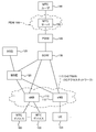
- the UE 105 on the MTC device 100, the UE 105, the base station wirelessly connected to the MTC device 100 and the UE 105 (eNB (eNode B) in E-UTRAN, NB (Node B) in UTRAN) 110, E-UTRAN 115 MME (Mobility Management Entity) 120 in charge of mobility management of the MTC device 100 and UE 105, SGW (Serving Gateway, MAG (Mobility Anchor Gateway): Mobility Anchor Point) for controlling user data distribution to the E-UTRAN 115 of the MTC device 100 and UE 105 130), PGW (Packet Gateway, HA Home Agent: Home) that performs address assignment to MTC device 100 and UE 105, user data transfer between PDN (Packet Data Network) 155 and SGW 130, and path control Agent) and LMA (also referred to as Local Mobility Anchor) 140, HSS (Home Subscriber Server) 125 that manages and holds subscription data (Subscription data) and communication context of MTC device 100 and UE 105
- MTC server 150 which is a server that provides communication control and status management by the MTC device 100, and application services, and from the MTC user 160 that performs application management / control and application data management for the MTC device 100 and the MTC server 150
- An example of a configured network configuration is shown.
- the MTC device 100 when the MTC device 100 communicates with the MTC server 150 (server providing service) via the communication system, the MTC device 100 establishes a PDN connection and an EPS bearer with the PGW 140 (the following non-patent document). 3). Data acquired by the MTC device 100 (for example, sensing data such as smoke detection information in the smoke sensor) is transmitted to the PGW 140 through the established PDN connection and EPS bearer, and transferred from the PGW 140 to the MTC server 150. The MTC server 150 sends the data sent from the MTC device 100 to the MTC user 160 at a defined timing (for example, after receiving data from the MTC device 100 or after receiving a request message from the MTC user 160). provide.
- a defined timing for example, after receiving data from the MTC device 100 or after receiving a request message from the MTC user 160.
- the timing at which the data acquired by the MTC device 100 is transmitted to the MTC server 150 is the characteristics of the MTC device 100 (MTC Feature, hereinafter sometimes referred to as MTC function), the instructions of the communication system operator, the MTC service It depends on the content. For example, when the MTC device 100 is equipped with “Time Controlled” (time control) that is one of the functions of the MTC defined in Non-Patent Document 1, that is, the time during which the MTC device 100 performs the communication operation is limited. The MTC device 100 is permitted to access the MTC server 150 and transmits the acquired data only for a predetermined time (for example, assigned by the communication system operator or set by the MTC user 160). To do.
- Non-Patent Document 1 When the MTC device 100 is equipped with “PAM (Priority Alarm Message)” defined in Non-Patent Document 1, that is, the MTC device 100 can transmit a high priority message to the MTC server 150 / MTC user 160. In this case, when the MTC device 100 detects an event (for example, smoke detection, flame detection, theft, etc.), the message is transmitted with priority over other messages and transferred to the MTC server 150. Since PAM also corresponds to emergency information notification, transmission may be permitted at any timing without being restricted by the above “Time Controlled” due to application settings and communication operator policy.
- PAM Primary Alarm Message
- MTC Mobility Management Entity
- the MTC devices 100 are grouped into one group (hereinafter referred to as MTC).
- MTC International Mobile Subscriber Identity
- the HSS 125 can collect and manage all or part of the subscription data normally managed and held for each MTC device 100 in units of MTC groups.
- the MTC device 100 When the MTC device 100 is equipped with “Low mobility”, that is, the MTC device 100 moves only within a limited range (for example, moves only within a predetermined TA (Tracking Area) or cell range), or When fixed as a device like a vending machine, for example, TAU (Tracking Area Update) or RAU (Routing Area Update) for updating the location information can be suppressed compared to the UE 105, It is possible to reduce a load caused by mobility control in a communication node (for example, the MME 120 or the PGW 140) that performs mobility management with the MTC device 100.
- a communication node for example, the MME 120 or the PGW 140
- the MTC device can be equipped with a plurality of MTC functions (Features) based on the request of the MTC user 160. Further, according to the demand between the MTC device 100 and the MTC server 150 / MTC user 160, the MTC function of the MTC device 100 can be activated / deactivated (function or operation). Enable / disable).
- a plurality of MTC devices 100 (“Time controlled”, “PAM”, “Group based”, “Low mobility”) are mounted ( For example, consider a case where an apartment fire occurs in an environment where smoke sensors, flame sensors, and human sensors form one MTC group and the security of the apartment group is monitored. At this time, an MTC device 100 (for example, a smoke sensor) detects an event (smoke) that triggers the occurrence of a fire (smoke generation), and then another MTC device (for example, a human sensor) Human presence).
- the MTC device (MTC device A 100A) mounted on the smoke sensor establishes a PDN connection for communicating with the MTC server 150 (step S2001 in FIG. 2: PDN connection already established).
- the MTC device B 100B similarly establishes a PDN connection with the PGW 140 (step S2004 in FIG. 2: PDN connection already established).
- step S2002 in FIG. 2 event detection
- step S2003 event notification message @device A in FIG. 2
- a plurality of MTC devices B100B (other smoke sensors, flame sensors, etc.) installed in other locations also detect the occurrence of fire (step S2005 in FIG. 2), A high event notification message (for example, PAM) is used for reporting (step S2006 in FIG. 2).
- PAM high event notification message
- other smoke sensors similarly detect smoke
- the MTC device B 100B mounted on the other smoke sensors also reports smoke detection using a high priority event notification message (eg, PAM).
- the flame sensor detects ultraviolet rays emitted from the flame
- the MTC device B 100B mounted on the flame sensor notifies the MTC server 150 that ultraviolet rays emitted from the flame are detected with a high priority message. Notification is also possible.
- the number of other smoke sensors and flame sensors installed may be enormous.
- the MTC server 150 has already detected the fire occurrence by the PAM from the first MTC device A100A, the PAM is also obtained from the many MTC devices B100B that have detected the fire occurrence. And all received PAMs must be processed. As a result, the processing load on the MTC server 150 and the traffic load on the network increase. In addition, there may be a problem in that it is impossible to quickly respond to a disaster because transmission / reception of event detection (for example, the presence / absence of a person in the above case) required after the occurrence of a fire is delayed or lost.
- event detection for example, the presence / absence of a person in the above case
- the same problem may occur in a scenario in which, for example, a plurality of gas sensors installed in a factory transmits a gas leak detected to the MTC server 150 using PAM. That is, also in this case, a redundant processing load and a network traffic load increase.
- a certain MTC device 100 is notified of the event by preferentially notifying the network side that an event (smoke generation) has been detected.
- Event notification messages (redundant event notification messages) that are similarly notified in high priority mode from a number of MTC devices 100 even though the network side can grasp that an event (for example, a fire has occurred) ) Must be processed, which increases the processing load.
- network traffic increases due to the flow of a large number of event notification messages. For example, information indicating the occurrence of another event may be delayed or may not reach the network side. There is also sex.
- the present invention is to reduce the load on the network side (processing load of MTC server and communication system entities (eNB, MME, SGW, PGW, etc.) and traffic amount in the network).
- An object is to provide a communication node and a network node.
- the present invention also provides an MTC server and an entity (eNB) of a communication system when an MTC device that communicates with the MTC server through the communication system detects an event in an environment where a large number of MTC devices are installed. , MME, SGW, PGW, etc.) and a communication node and network node for reducing the amount of traffic in the network.
- the present invention provides a communication node for reducing the processing load of the MTC server and communication system entities (eNB, MME, SGW, PGW, etc.) and the amount of traffic in the network when congestion is detected on the network side. And it aims at providing a network node.
- MTC server and communication system entities eNB, MME, SGW, PGW, etc.
- the communication node of the present invention responds to a control message transmitted by an entity on the network side in response to a notification from another communication node, or a communication status with the other communication node.
- a control message to be transmitted, the control message instructing to change the communication mode of the communication node that meets the specific condition is received from the network side, and the specific condition included in the received control message is received.
- the communication control unit controls to change the communication mode when the specific condition is satisfied.
- the communication node of the present invention is a normal mode in which the communication control unit transmits sensing data detected by a sensor for detecting the occurrence of a specific event with normal priority, or The event notification message for notifying that the occurrence of the specific event is detected by the sensor is transmitted in any one of the transmission modes of the high priority mode for transmitting with a priority higher than the priority of the normal mode.
- An operation mode control unit to control; A transmission unit for transmitting the event notification message in the high priority mode or transmitting the sensing data in the normal mode to a network node; A message transmitted as a response to the event notification message from the arbitrary communication node from the network node that has received the event notification message notifying that the occurrence of a specific event has been detected from the arbitrary communication node, A message receiving unit for receiving the message instructing to change the mode to the normal mode or to maintain the normal mode; When the message is received, a mode transition determination unit that determines whether to change the transmission mode to the normal mode or to maintain the normal mode, Have When the mode transition determination unit determines that the transmission mode is changed to the normal mode or is maintained as the normal mode, the operation mode control unit may change the transmission mode to the normal mode or The normal mode is maintained.
- the communication node of the present invention includes the communication control unit, A message sent from a network node when a congestion state is detected in the network, and a communication node having a time-tolerance function defined in machine-type communication suppresses connection to the network A message receiving unit for receiving the message including the information to instruct; When receiving the message, a function determination unit that determines whether or not the own communication node has the time tolerance function; When it is determined that the device has the time tolerance function, the connection established with the network is disconnected, or data transmission is performed while maintaining the connection established with the network. Or a connection control unit that controls not to make a connection request to the network when a connection is not established with the network, Have.
- MTC server and communication system entities eNB, MME, SGW, PGW, etc.
- the network node is a control message transmitted by an entity on the network side in response to a notification from another communication node, or a communication status with the other communication node.
- a control message to be transmitted in response to the information including an instruction to change the communication mode of the communication node that satisfies the specific condition, and the communication control unit that controls to change the communication mode of the communication node that satisfies the specific condition Have With this configuration, it is possible to reduce the load on the network side (such as the processing load of the MTC server and the amount of traffic in the network).
- the network node of the present invention includes a normal mode in which the communication control unit transmits sensing data detected by a sensor for detecting the occurrence of a specific event with normal priority, Alternatively, an event notification message for notifying that the occurrence of the specific event has been detected by the sensor is transmitted in one of the transmission modes of the high priority mode in which the event notification message is transmitted with a higher priority than the priority of the normal mode.
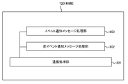
- a network node connected to the plurality of communication nodes A receiving unit for receiving the event notification message for notifying that the occurrence of a specific event is detected from any one of the plurality of communication nodes; As a response to the event notification message, a message creating unit that creates a message instructing to change the transmission mode to the normal mode or to maintain the normal mode; A message transmission unit for transmitting the message to the plurality of communication nodes; Have.
- the communication control unit of the network node of the present invention includes: When a congestion state is detected, a communication node having a time control function defined in machine type communication includes a message creation unit that includes information instructing to suppress connection to the network in the message Have.
- a communication node and network for reducing the processing load of the MTC server and communication system entities eNB, MME, SGW, PGW, etc.
- the traffic amount in the network The purpose is to provide nodes.
- the present invention has the above-described configuration, and reduces the load on the network side (processing load of MTC server and communication system entities (eNB, MME, SGW, PGW, etc.) and traffic amount in the network). Has an effect. Also, in an environment where a large number of communication nodes (MTC devices) are installed, when the communication node that communicates with the server (MTC server) through the communication system detects and notifies an event, the processing load on the server And the effect of reducing the amount of traffic in the network. In addition, when congestion is detected on the network side, there is an effect of reducing the processing load of the MTC server and communication system entities (eNB, MME, SGW, PGW, etc.) and the amount of traffic in the network.
- the present invention allows the transmission mode of the MTC device, which normally transmits detected information to the MTC server 150 in the normal mode, to be switched to the high priority mode in an emergency (when an event occurs). Has the effect of being able to.
- the figure which shows an example of a structure of the communication system common to the 1st-6th and 8th embodiment of this invention, and the prior art Sequence chart for explaining an example of operation in the prior art The sequence chart for demonstrating an example of the operation
- the figure which shows the example of a format of the event notification message (event information) @device A in the 2nd-7th embodiment of this invention The figure which shows the example of a format of the reverse event notification message (event information) in the 2nd-7th embodiment of this invention
- the figure which shows an example of the event group information in the 2nd-7th embodiment of this invention The figure which shows an example of the transmission mode transition of the MTC device in the 2nd-7th embodiment of this invention
- positioning of each MTC device in order to demonstrate 1st and 2nd Embodiment of this invention concretely
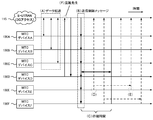
- the figure which shows an example of the transition of the transmission mode in each MTC device, in order to demonstrate the 1st and 2nd Embodiment of this invention concretely
- maintains in order to demonstrate the 1st and 2nd embodiment of this invention concretely
- Sequence chart for explaining an example of operation for suppressing transmission of redundant event notification messages in the fifth exemplary embodiment of the present invention
- Explanatory drawing for demonstrating the operation
- the sequence chart for demonstrating an example of the operation
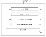
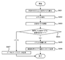
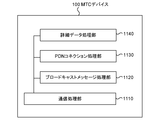
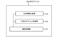
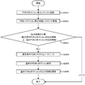
- the figure which shows an example of a structure of the MTC device in the 8th Embodiment of this invention The flowchart which shows an example of the reception processing flow of the MTC device in the 8th Embodiment of this invention
- the flowchart which shows an example of the detailed reception processing flow of the MTC device in the 8th Embodiment of this invention The sequence chart for demonstrating an example of operation
- the figure which shows the example of a format of the request message of the release of the PDN connection in the 9th Embodiment of this invention The figure which shows an example of a structure of the MTC device in the 9th Embodiment of this invention.
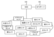
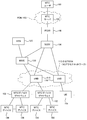
- FIG. 1 is a diagram showing an example of a system configuration common to the first to third embodiments of the present invention.
- the communication system illustrated in FIG. 1 includes at least the MTC device 100, the UE 105, the MTC device 100, the base station (eNB or NB) 110 wirelessly connected to the UE 105, and the MTC device 100 on the E-UTRAN 115.
- the base station eNB or NB
- MME 120 in charge of mobility management of UE 105, SGW 130 that performs user data distribution control to E-UTRAN 115 of MTC device 100 and UE 105, PGW 140 that performs address allocation to MTC device 100 and UE 105, user data transfer between PDN 155 and SGW 130, and path control , Communication control and status management by the HSS 125 and the MTC device 100 that manage and hold the subscription data and communication context of the MTC device 100 and the UE 105 And a MTC user 160 to implement the management and control of the application data management applications for a MTC server 150, MTC device 100 and MTC server 150 provides a server for such application services.
- the MTC user 160 may use an AAA (Authentication, “authorization” and “Accounting”) server instead of the HSS 125.
- the AAA server and the HSS 125 may be mounted on the same device physically or logically.
- the MTC server 150 is located in the PDN 155.
- the MTC server 150 may be located in the operator domain of the communication system.
- the PGW 140 may be responsible for the function of the MTC server 150.
- the MTC device 100 has at least one or more communication interfaces, and can be connected to a communication system (for example, E-UTRAN 115).
- the MTC device 100 may be connected to a network other than the illustrated communication system (for example, a UTRAN, WLAN (Wireless LAN) network, or WiMAX network) simultaneously or exclusively.
- the MTC device 100 can communicate with the MTC server 150 through the connected communication system, and the MTC server 150 can communicate with the MTC user 160.
- the MTC device 100 performs communication while coexisting with the conventional UE 105 in the communication system.
- the MTC device 100 and the UE 105 are connected to different eNBs 110, but the eNB 110 for the MTC device is not distinguished and may be connected to any eNB 110.
- the MTC device 100 may be connected to the eNB 110 for the MTC device 100.
- each MTC device 100 is assigned an ID (hereinafter referred to as a device ID) for identifying the MTC device 100 in the same manner as the UE 105.
- a device ID an ID for identifying the MTC group
- the MTC device 100 is assigned an ID (hereinafter referred to as a device type ID) for identifying the device type (for example, smoke sensor).
- the type of the MTC device 100 is determined by the type of apparatus on which the MTC device 100 is mounted or connected. Further, the type of the MTC device 100 may be set by an MTC server, an MTC user, or an operator of the communication system.
- the MTC device 100, the communication system entity (for example, the MME 120, the PGW 140, etc.), and the MTC server 150 can identify the type of the MTC device 100 without using the device type ID (for example, the device).
- the device type ID for example, the device.
- a part of the bit string indicating the device type for example, deriving the type of the MTC device 100 from the upper or lower several bits
- the MTC device 100 can be uniquely identified by using, for example, IMEI (International Mobile Equipment Identity) or IMSI (International Mobile Subscriber Identity), there is no need to newly assign the device ID.
- IMEI International Mobile Equipment Identity
- IMSI International Mobile Subscriber Identity
- the group ID shares a PDN connection or EPS bearer for transferring data
- the MTC device 100 represented in the MTC group has established a PDN connection or EPS bearer with the communication system.
- the PTC connection ID, EPS bearer ID, and APN Access (Point Name) are used to select the MTC group. If it can be identified, there is no need to assign a new one.
- each MTC device 100 may have an MTC function (MTC Features) incorporated in advance by, for example, the MTC user 160 (for example, writing to a SIM card, writing to the storage memory of the MTC device 100), or a network
- the apparatus for example, the MME 120 or the MTC server 150
- the MTC device 100 itself may enable / disable a desired MTC function.
- the HSS 125 holds various information related to MTC such as the device ID, group ID, device type ID, MTC function installed, MTC function validation / invalidation as described above. It is assumed that it is registered in subscription data and communication context. Further, the mobility control of the MTC device 100 in the E-UTRAN 115 is performed by the MME 120 in the same manner as the control for the UE 105.
- the MTC server 150 may be managed by an operator who operates the communication system, or may be managed by an operator other than the operator. In any case, it has an interface with the PGW 140 managed by the operator, and enjoys services related to user data transfer to / from the MTC device connected to the communication system and control of the MTC device in the communication system.
- the MTC server and the PGW 140 may be implemented in the same device, thereby concealing the implementation of the external interface in the device and reducing the device cost. it can.
- the MTC user 160 is an entity that manages and uses data acquired by each MTC device 100, and corresponds to a business operator, a company, and a control entity (PC, server, etc.) that performs data management.
- the MTC device 100 is incorporated in a vending machine
- the MTC user 160 is a company that performs sales aggregation and maintenance of vending machines.
- the MTC user 160 is considered to be a fire department, a security company, an insurance company, or a company in charge of reducing damage caused by a fire in a house.
- the MTC user 160 may be considered as an MTC user terminal used by a user who manages MTC as described above, or may be the same device as the MTC server 150 operated by a user who manages MTC. You may think.
- data exchanged between the MTC device 100 and the MTC server 150 is application-level data. Therefore, data transfer between the MTC device 100 and the PGW 140 is performed using a U plane (User plane: User plane) is assumed.
- U plane User plane
- the contents and nature of applications and services for example, data transfer services with urgency such as survivor confirmation
- requests from network operators of communication systems for example, network devices (for example, MME 120) are required.
- the MTC device 100 when detecting an event from the acquired data (also referred to as sensing data), the MTC device 100 that transmits a high-priority event notification message when an event is detected transmits a high-priority event notification message to the MTC server.
- the acquired data sensing data
- the acquired data is transmitted to the MTC server.
- the MTC device 100 is connected to the communication system (E-UTRAN 115) and can communicate with the MTC server 150 through the communication system.
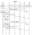
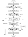
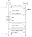
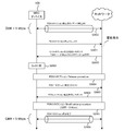
- FIG. 3 shows an example of system operation according to the first exemplary embodiment of the present invention (high-priority event due to the same event transmitted from a plurality of MTC devices 100 or an event caused by the event that caused the event) It is a sequence diagram for demonstrating the transmission suppression method of a notification message.
- FIG. 3 shows an example of a processing sequence in the system configuration shown in FIG.
- the MTC device 100 has the following characteristics.
- the MTC device 100 has “Time Controlled”, “PAM”, “Group based”, and “Low mobility” defined in Non-Patent Document 1. It is assumed that the MTC device 100 is managed as one MTC group together with a plurality of other MTC devices 100.
- the MTC device 100 in the MTC group is composed of “smoke sensor”, “flame sensor”, and “human sensor” (in fact, each sensor has a communication module that is the MTC device 100). Implemented).
- the smoke sensor detects a smoke concentration above a certain value (or a certain value continuously for a predetermined time), that is, when an event (smoke) is detected, there is a high possibility that a fire has occurred.
- High priority mode When a “flame sensor” detects an event (flame), it determines that there is a high possibility of a fire and sends a message with high priority (high priority mode), just like “smoke sensor”. .
- the “human sensor” detects an event the presence or absence of a person
- it transmits sensing data with a general priority also called a normal mode.
- the high priority mode is a state in which an event notification message having a high priority is transmitted when an event is detected.
- Normal mode is a state in which the acquired data is sent with a general priority without sending an event notification message with a high priority when an event is detected, or an event notification message with a general priority.
- the acquired data is also transmitted with a general priority.
- the message priority includes the EPS bearer QCI, EPS bearer bandwidth (for example, MBR (Maximum Bit Maximum Rate) or AMBR (Aggregate Maximum Maximum Bit Rate)), IMSI and IMEI values of the MTC device 100, PCC. (Policy and Charging Control), MTC Feature / type of MTC device 100 / priority or value defined for each MTC service may be defined.
- the MTC device A 100A and the MTC device B 100B are illustrated.
- the MTC device A 100A is an MTC device (“smoke sensor”) that first detects an event
- the MTC device 100B is another MTC device (“smoke” that belongs to the same MTC group as the MTC device A 100A.
- Sensor “ flame sensor ”,“ human sensor ”.
- the MTC device A 100A (smoke sensor) establishes a PDN connection for communicating with the MTC server 150 with the PGW 140 based on a conventional method (for example, Attach procedure shown in Non-Patent Document 3) (step S201 in FIG. 3). : PDN connection established).
- the MTC device B 100B also establishes a PDN connection with the PGW 140 based on a conventional method (for example, Attach procedure shown in Non-Patent Document 3) (step S206 in FIG. 3: PDN connection established).
- the MTC device A 100A detects an event (smoke) due to, for example, a fire (step S202 in FIG. 3: event detection).
- the MTC device A 100A that has detected the event transmits a message (noted here as event notification message @device A) for notifying the MTC server 150 that the event has been detected.
- event notification message @device A a message for notifying the MTC server 150 that the event has been detected.
- a message having a high priority indicates a PAM, a NAS / AS message having a higher priority than other NAS messages, or the like.
- This high priority message may be called (Priority) PriorityEvent Notification, Alarm ⁇ Signaling, Event Alert, Emergency ⁇ signaling, Event Detection Message, or the like.
- the event notification message @device A which is a high-priority message transmitted from the MTC device A 100A, is, for example, a PAM defined by Non-Patent Document 1 or a TAU (Tracking Area) described in Non-Patent Document 3.
- Update Used when establishing a PDN connection or EPS bearer when piggybacked (superimposed) on a location registration message such as Request, or when an event is detected when a PDN connection or EPS bearer is not established
- an IKE_SA_INIT message or an IKE_AUTH Request message used in Attach Request, Service Request, DS-MIPv6 bootstrapping based on IKEv2 defined in Non-Patent Document 4 may be used.
- a Bearer Modification Request message may be used.
- the event notification from the MTC device 100 can be implemented with little modification without introducing a new message.
- an entity of the communication system receives a high-priority event notification message notifying that an event has been detected from the MTC device A 100A belonging to the MTC group
- the event is sent to the MTC server 150 via the SGW 130 / PGW 140. Forward the notification message @device A.
- an entity of the communication system eg, MME 120
- may receive a subsequent high-priority event notification message the same event (eg, smoke occurrence) or an event that caused that event (eg, smoke occurrence) (eg, smoke occurrence).
- a message for suppressing transmission of an event notification message (for example, PAM) due to an event (for example, occurrence of a flame) caused by a fire occurrence)
- An event notification message for example, PAM
- the Entity for example, the MME 120
- the communication system may store a parameter indicating a stop of transmission of the same type of high priority notification message in the reverse notification message.
- this reverse event notification message has a higher priority than other messages or a general priority depending on the determination of the transmission source (for example, MME 120) of the reverse event notification message (for example, presetting by the operator of the communication system). You may send it with If a reverse event notification message is sent with a higher priority than other messages, the message will be overloaded even if the message source is overloaded and processing of general priority messages is abandoned. A reverse event notification message can be sent. Further, instead of the reverse event notification message having a high priority, the reverse event notification message may be sent with a general priority. In this case, it is not necessary to set the message priority.
- the MME 120 may transmit a reverse event notification message when a predetermined number of event notification messages are received within a predetermined period or when a predetermined number of event notification messages are received.
- a reverse event notification message when predicting that the same event notification message will increase in the future, by sending a reverse event notification message to suppress those occurrences, when judging from a single event notification message Compared to this, it is possible to effectively issue a suppression message (reverse event notification message) and to effectively use communication resources and bandwidth (when judging from a single event notification message, the event notification message is received). Every time you send a reverse event notification message, you waste communication resources and bandwidth).
- the MME 120 sends the subscription data corresponding to the MTC device A 100A from the HSS 125 to determine whether the MTC device A 100A belongs to the MTC group, and if the MTC device A 100A belongs to the MTC group. It may be determined whether the group ID is acquired and registered. Alternatively, from the group ID stored in the message by the MTC device A 100A, it may be determined whether the MTC device A 100A belongs to a group (or which group it belongs to). In addition, the MME 120 checks whether the MTC device A 100A belongs to the MTC group by a method other than the method in which the MME 120 already holds the subscription data or acquires the subscription data from the HSS 125 (for example, an inquiry to an external server). May be.
- the target for transmitting the reverse event notification message is all MTC devices (MTC device A 100A and MTC device B 100B) under the MTC group to which the MTC device A 100A that detected the event belongs, but “Group based”.
- MTC device A 100A and MTC device B 100B MTC devices under the MTC group to which the MTC device A 100A that detected the event belongs, but “Group based”.
- all the MTC devices 100 under the eNB 110 or the MME 120 (or a specific Tracking Area) to which the MTC device A 100A is connected may be the transmission target of the reverse event notification message.
- an event notification message having a high priority due to the same event from the MTC device 100 located in a specific area can also be avoided.
- the ID of the eNB 110 or the address of the eNB 110 may be used instead of the group ID.
- the reverse event notification message may be transmitted not by broadcast but by multicast or unicast. Thereby, the impact on the entire system can be reduced by limiting the control range (notification range).
- this reverse event notification message may be transmitted by an entity (for example, eNB 110, PGW 140, etc.) in a communication system other than the MME 120 or the MTC server 150.
- the reverse event notification message is a subsequent high-priority event notification message (the same event or an event notification message (for example, PAM) generated by an event that caused the event). It is a message to suppress.
- the reverse event notification message is a message requesting the MTC device 100 to operate in the normal mode, and the MTC device 100 that has received the reverse event notification message is operating in the high priority mode. The mode transitions to the normal mode, and when operating in the normal mode, the normal mode is maintained as it is.
- a reverse event notification message other than avoiding a high-priority event notification message for example, PAM
- PAM high-priority event notification message
- the MTC device that has received the reverse event notification message is, for example, an allowable priority level indicated by the network side stored in the reverse event notification message, or a context (for example, a message having a priority level of 3 or higher when the congestion level is 3). Transmission data) or application data may be used to select / determine sensing data that can be transmitted.
- the MTC device 100 transmits the sensing data to be transmitted in consideration of the priority from the mode in which the priority of the sensing data to be transmitted is not determined (for example, the normal mode). You may switch to the mode (for example, high priority mode) which can be selected / decided.
- the MTC device 100 can recognize a plurality of priority levels, a message indicating a change in the priority level transmitted by a device on the network side (for example, the MTC server 150 or the MME 120) For example, the MTC device 100 may perform processing such as changing the priority level of a message to be transmitted. As a result, in a situation where the network is congested and packet loss occurs, the priority level of the message transmitted by the MTC device 100 itself is taken into account, and the message to be transmitted is selected, thereby further increasing the congestion state. Can avoid making.
- the MTC device A 100A that has received the reverse event notification message performs mode transition from the high priority mode to the normal mode as shown in FIG. 7 in accordance with the reverse event notification message (step S205: mode switching). Thereafter, the MTC device A 100A transmits the sensing data in the normal mode (step S210 in FIG. 3: acquisition data transmission). Note that the acquisition data transmission in step S210 in FIG. 3 is performed at an arbitrary timing after the mode switching in step S205.
- the MTC device A 100A that first transmitted the event notification message performs the mode transition from the high priority mode to the normal mode by receiving the reverse event notification message, but the event notification message in the high priority mode. The mode may be shifted to the normal mode by itself immediately after the transmission is performed, or the notification in the high priority mode may be continuously performed as it is for the MTC device A 100A that has transmitted the event notification message.
- the MTC device B 100B that has received the reverse event notification message notifies the MTC server 150 that the event has been detected using an event notification message (for example, PAM) having a high priority when the MTC device B 100B has detected the event itself.
- an event notification message for example, PAM
- PAM a device having a high priority when the MTC device B 100B has detected the event itself.
- a device for example, another smoke sensor or flame sensor
- Mode switching After that, even if an event is detected (step S208 in FIG. 3: event detection), a high-priority event notification message (for example, PAM) is not transmitted (step S207 in FIG. 3: mode switching).
- Sensing data is transmitted in the normal mode (step S209 in FIG. 3: acquisition data transmission).
- the MTC device B 100B is an MTC device such as a human sensor that transmits sensing data to the MTC server 150 in the normal mode from the normal time
- the transmission mode is maintained in the normal mode.
- an event notification message may be notified with a general priority instead of a high priority, and then sensing data may be transmitted.
- the MTC device 100 for example, a smoke sensor or a flame sensor
- the mode transitions to the normal mode. For example, after a predetermined time (for example, a lifetime value is notified by the reverse event notification message), or a message transmitted from the MME 120 or the MTC server 150 ( For example, the NAS mode may be received to return from the normal mode to the high priority mode. Thereby, after one event is completed, it is possible to return to the same operation as before (not shown in FIG. 3).
- detected events / acquired data are transmitted to the MTC server 150 in the normal mode periodically or at a predetermined timing.
- the smoke sensor detects smoke, there is a high possibility that a fire has occurred, so the information on the presence or absence of a person is highly important. Therefore, the information regarding the presence or absence of the person detected by the human sensor must be notified using an event notification message (for example, PAM) with a high priority instead of a general priority (normal mode).
- PAM event notification message
- an event detected by the MTC device 100 (human sensor), which normally transmits information about the presence or absence of a person in the normal mode, is detected by the MTC device 100 belonging to the same MTC group or the surrounding MTC devices 100 Therefore, there is a desire to be able to notify event detection (information about the presence or absence of a person) with a high priority event notification message (for example, PAM).
- a high priority event notification message for example, PAM
- the human sensor may be set to notify an event notification message having a high priority when, for example, the walking speed and density of a certain person are exceeded.
- the MTC server 150 when a message of a certain value or more is received from a peripheral MTC device 100 in an environment where communication between the MTC devices 100 is possible in response to a request from an operator of the communication system, the MTC server 150, the MTC user 160, or the like (for example, In an environment such as an ad hoc network, when a packet of a certain value or more is transferred within a certain time), it may be set to notify an event notification message with a high priority.
- the MTC device 100 When the MTC device 100 detects an event, the MTC device 100 notifies only an event notification message, transmits only acquired data, or transmits both an event notification message and a message that transmits acquired data. Whether to do this is determined by, for example, the MTC device 100 itself, the operator of the communication system, the MTC server 150, the MTC user 160, and the like.
- the communication system entity or the MTC server 150 belongs to the target MTC group after receiving the event notification message with high priority transmitted from the MTC device 100 that detected the event.
- the method for transmitting a message for the purpose of suppressing a high-priority event notification message that may be transmitted by a plurality of MTC devices 100 all the devices are uniformly instructed to stop transmission.
- a necessary event notification message for example, a PAM from a flame sensor or a human sensor after a smoke sensor transmits a PAM
- the improved system of the first embodiment is shown in the second embodiment.
- FIG. 4 shows an example of system operation according to the second exemplary embodiment of the present invention (high-priority event due to the same event transmitted from a plurality of MTC devices 100 or an event caused by the event that caused the event). It is a sequence diagram for demonstrating the transmission suppression method of a notification message.
- FIG. 4 shows an example of a processing sequence in the system configuration shown in FIG.
- the MTC device 100 has the following characteristics.
- the MTC device 100 has “Time Controlled”, “PAM”, “Group based”, and “Low mobility” defined in Non-Patent Document 1. It is assumed that the MTC device 100 is managed as one MTC group together with a plurality of other MTC devices 100. Further, the MTC device 100 in the MTC group is assumed to be composed of “smoke sensor”, “flame sensor”, and “human sensor”. When the “smoke sensor” detects an event (smoke), it determines that there is a high possibility that a fire has occurred, and transmits a message with high priority (high priority mode).
- the “flame sensor” detects an event (flame), it determines that there is a high possibility that a fire has occurred, and, like the “smoke sensor”, transmits a message with high priority (high priority mode).
- the “human sensor” detects an event (the presence or absence of a person), it transmits sensing data in the normal mode.
- FIG. 4 shows an MTC device A 100A and an MTC device B 100B in order to identify the MTC devices 100 in the MTC group.
- the MTC device A 100A is an MTC device (“smoke sensor”) that first detects an event
- the MTC device B 100B is another MTC device (“smoke” that belongs to the same MTC group as the MTC device A 100A.
- Sensor “ flame sensor ”,“ human sensor ”).
- the MTC device A 100A (smoke sensor) establishes a PDN connection for communicating with the MTC server 150 with the PGW 140 based on a conventional method (for example, Attach procedure shown in Non-Patent Document 3) (step S301 in FIG. 4). : PDN connection established).
- the MTC device B 100B establishes a PDN connection with the PGW 140 based on a conventional method (eg, Attach procedure shown in Non-Patent Document 3) (step S308 in FIG. 4: PDN connection established).
- the MTC device A 100A detects an event (smoke) due to, for example, a fire (step S302 in FIG. 4: event detection).
- event notification message that stores the detected event information (for example, a smoke generation flag, a device type ID, and the like).
- an event notification message here, referred to as event notification message (event information) @device A
- event notification message event information @device A
- the MTC device A 100A (smoke sensor) detects smoke, it is predicted that there is a high possibility that a fire has occurred, and the MTC device A 100A notifies the MTC server 150 using a high-priority message. . At this time, the MTC device A 100A may store sensing data (smoke density) in the event notification message.
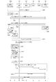
- FIG. 5A is a diagram illustrating a format example of an event notification message (event information) @device A as an example of a message that the MTC device A 100A transmits to the MTC server 150 through the communication system in step S303 of FIG.
- the MTC device A 100A adds, for example, at least an event flag field to the conventional NAS message field.
- the event flag field is a field for indicating that the MTC device A 100A has detected an event (for example, a smoke generation flag when the MTC device A 100A is a smoke sensor). Note that the type of the detected event may be written together.
- a sensing data field and a device type ID field may be added. Further, the sensing data field is data (for example, smoke density when the MTC device A 100A is a smoke sensor) that should be transmitted to the MTC server 150 at an early stage (that is, together with the event notification) when an event is detected, for example. It is a field for storing.
- the device type ID field is a field for storing information for identifying the type of the MTC device A 100A that detected the event. For example, when the MTC device A 100A is a smoke sensor, information that can be identified as “smoke sensor” is stored (for example, determination is made based on a bit string indicating the IMEI device type).
- the event flag field, sensing data field, and device type ID field added to these conventional NAS messages may be embedded in the NAS message field.
- a message for example, for MTC
- MTC Mobility Management Entity
- an event notification message (event information) @device A is transmitted in the C plane.
- the MTC device A 100A or the MTC server 150 / MTC user 160 can confirm that the MTC device 100 has detected an event without using the information in the event flag field. For example, “Time controlled” is applied. If the MME 120 can determine that the MTC device 100 has detected an event to be notified in the high priority mode when the MTC device 100 has accessed outside the allocated time, the event flag field may be omitted. Good.
- the sensing data field may be omitted.
- the device type ID field may be omitted if the device type can be derived from the device ID stored in the conventional NAS message field. Further, since the information is stored in the device type ID field, it can be confirmed that the MTC device A 100A has detected the event (for example, when the device type ID indicating the smoke sensor is stored, the smoke detection event is simultaneously displayed). The event flag field may be omitted as well.
- the event notification message (event information) @device A which is a high-priority message transmitted from the MTC device A 100A, is described in, for example, PAM defined by Non-Patent Document 1 and Non-Patent Document 3.
- a piggyback superimposition
- a location registration message such as a TAU (Tracking Area Update) request
- a PDN connection or EPS bearer is established.
- the IKE_SA_INIT message or the IKE_AUTH Request message used in AttachMRequest, Service Request, DS-MIPv6 bootstrapping based on IKEv2 defined in Non-Patent Document 4 may be used.
- a Bearer Modification Request message may be used.
- an entity of the communication system for example, MME 120
- necessary information for example, event flag, sensing data, device type ID
- an event notification message (event information) @device A is transferred to the MTC server 150 through the SGW 130 / PGW 140.
- the MME 120 extracts event information (event flag / device type ID) from the event notification message (event information) @device A, and reverse event notification message (event information) (reverse PAM, congestion avoidance message, Time ⁇ ⁇ ⁇ ⁇ ⁇ Tolerant Indication, congestion indication, congestion priority indication, PAM reduction indication, etc.) and transmitted to all the MTC devices 100 in the MTC group to which the MTC device A 100A belongs (step S304 in FIG. 4). Reverse event notification message (event information)).
- this reverse event notification message has a higher priority than other messages or a general priority depending on the determination of the transmission source (for example, MME 120) of the reverse event notification message (for example, presetting by the operator of the communication system). You may send it with If a reverse event notification message is sent with a higher priority than other messages, the message will be overloaded even if the message source is overloaded and processing of general priority messages is abandoned. A reverse event notification message can be sent. Further, instead of the reverse event notification message having a high priority, the reverse event notification message may be sent with a general priority. In this case, it is not necessary to set the message priority.
- the MME 120 may transmit a reverse event notification message when a predetermined number of event notification messages are received within a predetermined period or when a predetermined number of event notification messages are received.
- a reverse event notification message when predicting that the same event notification message will increase in the future, by sending a reverse event notification message to suppress those occurrences, when judging from a single event notification message Compared to this, it is possible to effectively issue a suppression message (reverse event notification message) and to effectively use communication resources and bandwidth (when judging from a single event notification message, the event notification message is received). Every time you send a reverse event notification message, you waste communication resources and bandwidth).
- the MME 120 subscribes to the MTC device A 100A in order to confirm whether the MTC device A 100A belongs to the MTC group or, if it belongs to the MTC group, to which MTC group.
- the data may be acquired from the HSS 125 to determine whether the group ID is registered. Alternatively, it may be determined from the event notification message (event information) in step S303 @ the group ID stored in the device A (not shown in FIG. 5A).
- the target for transmitting the reverse event notification message is all MTC devices (MTC device A 100A and MTC device B 100B) under the MTC group to which the MTC device A 100A that detected the event belongs, but “Group based”.
- MTC device A100A is connected, all the MTC devices 100 under the eNB 110 may be set as transmission targets of the reverse event notification message.
- an event notification message having a high priority due to the same event from the MTC device 100 located in a specific area can be suppressed.
- the event notification message with high priority can be suppressed without considering the concept of the MTC group, there is an advantage that it is not necessary to use a group ID or the like.
- an eNB ID or an eNB address (and S1-U TEID corresponding to the EPS bearer of the MTC device 100) may be used.
- the MME 120 can confirm the transmission partner in advance, the reverse event notification message may be transmitted not by broadcast but by multicast or unicast. Thereby, the impact on the entire system can be reduced by limiting the control range (notification range).
- the MME 120 transmits the reverse event notification message (event information) to all the MTC devices 100 of the MTC group, for example, the group ID and device type of the MTC group that is the transmission destination of the reverse event notification message (event information)
- the fact that the reverse event notification message (event information) has been transmitted together with the ID is stored as reverse event notification message (event information) transmitted information.
- the stored reverse event notification message (event information) transmitted information is the event notification message (the event caused by the same event from the MTC device 100 of the same device type in the same MTC group or an event caused by the event that caused the event) ( This is used as a parameter for the MTC device 100 to determine not to transmit the same reverse event notification message (event information) again when the event information is received.
- the MME 120 can confirm the type of the MTC device 100 as described above (for example, the type of the MTC device 100 can be confirmed from the device ID of the MTC device (for example, the device type of the device ID is changed). A part of a bit string (for example, upper or lower few bits), or a device ID can be acquired by notifying the external server of the device ID), or an event notification message (event) as shown in FIG. 5A Information) @Device type ID is also stored in device A).
- the MME 120 displays an event group information label (event group information and event group information to indicate which event group information is used among the plurality of event group information).
- the associated information is stored in a reverse event notification message (event information) and transmitted.
- the method of determining which event group information the MME 120 uses is, for example, using information registered in subscription data (for example, information in which event information and event group information are paired).
- the MTC server 150 / MTC user 160 may make the determination based on the specifications, registration information, setting information, etc. of the MTC service set in advance.
- the above determination (which event group information is used) by the MME 120 is an event notification message (event information) transmitted by the MTC device 100 after notifying that a plurality of event group information is held. May be implemented.
- FIG. 5B illustrates a reverse event notification message (event information) as an example of a message that the MME 120 broadcasts to all the MTC devices 100 (including the MTC device B 100B) of the MTC group to which the MTC device A 100A belongs in step S304 of FIG. It is a figure which shows the example of a format.
- the MME 120 transmits a message in which an event flag field, a device type ID field, and an event group information label field are added to the conventional NAS reply message field.
- the event flag field is a field for indicating that the MTC device 100 has detected an event.
- the event flag field is also used as a field for identifying that this message is a reverse event notification message.
- the device type ID field is a field for storing information (for example, smoke sensor) of the type of the MTC device 100 that has detected the event. In the device type ID field, for example, information for identifying the type of the MTC device 100 that is the transmission source of the event notification message that triggered the transmission of the reverse event notification message is stored.
- the information stored in the device type ID field must be associated with information registered in event group information (see FIG.
- the event group information label field is a field used when the MTC device 100 holds a plurality of event group information, for example.
- an event group information label for example, fire, earthquake, burglary, building collapse, landslide, etc. is stored by the MME 120 in order to determine which event group information the MTC device 100 uses. Is done.
- a reverse event notification message (event information) is transmitted in the C plane.
- the message transmitted in the conventional U plane It can be any field.
- the MTC device 100 does not use the information in the event flag field stored in the reverse event notification message (event information) from the MME 120, the same MTC group or the surrounding MTC devices 100 detected the event. If it can be confirmed (for example, it can be confirmed from the reception of a message outside the time allocated by “Time controlled”), the event flag field may be omitted.
- the event group information label field may be omitted. For example, by storing only the device type ID in the reverse event notification message transmitted from the network device (for example, the MME 120) without storing the event group information label, the MTC device 100 that first transmitted the event notification message Only event notification messages from the same type of MTC device 100 can be suppressed.
- event flag field in addition to these conventional NAS messages may be embedded in the NAS reply message field.
- the reverse event notification message (event information) transmitted from the MME 120 is, for example, a Paging message described in Non-Patent Document 3 or Non-Patent Document 5, a Bearer-Modification-Request message, or a PAM defined by Non-Patent Document 1.
- the TAU Accept message described in Non-Patent Document 3 or the IKE_SA_INIT message or IKE_AUTH Response message used in DS-MIPv6 bootstrapping based on IKEv2 defined by Non-Patent Document 4 may be used.
- the entity that refers to the event information stored in the event notification message (event information) @device A, stores the referenced event information in the reverse event notification message (event information), and broadcasts is not the MME 120.
- the PGW 140 or the MTC server 150 may be used. If the device type ID stored in the event notification message (event information) @device A and the device type ID stored in the reverse event notification message (event information) are guaranteed to be related. , It does not necessarily have to match. However, also in this case, it is necessary that the information stored in the reverse event notification message (event information) and the information registered in the event group information (for example, device type ID) are guaranteed to be related. is there.
- the MTC device 100 included in the event information or the conventional NAS message is identified instead of the device type ID.
- the MTC device 100 is stored in the reverse event notification message (event information) based on the IP address or the device ID. If the device type ID can be confirmed, there is no need to use the device type ID stored in the event notification message (event information) @device A.
- the MTC device 100 in the MTC group that has received the reverse event notification message (event information) extracts the device type ID stored in the reverse event notification message (event information). Then, it is confirmed whether or not it matches the device ID / device type ID of the MTC device B 100B itself (step S309 in FIG. 4: checks whether it matches the own type ID). If the device type ID extracted from the reverse event notification message (event information) matches its own device ID / device type ID by this confirmation, the MTC device 100 transitions to the normal mode ( If it was originally in normal mode, keep it as it is).
- the device type ID extracted from the reverse event notification message is the MTC device 100 (in this case, the MTC device) that has transmitted the event notification message (event) that triggered the transmission of the reverse event notification message. A100A). That is, the MTC device B 100B determines whether an event notification message is transmitted from the same type of MTC device 100 as the own device, and confirms that the event notification message has already been transmitted from the same type of MTC device 100 as the own device. If it is possible, the operation is performed in the normal mode so as not to transmit the event notification message in the high priority mode.
- the MTC device B 100B determines whether or not to switch the mode to the high priority mode based on the device type ID included in the received reverse event notification message (event information). When it is confirmed that it is necessary to switch the mode to the high priority mode, the mode is switched to the high priority mode (or the high priority mode is maintained if it was originally operating in the high priority mode) (see FIG. Step S310: Determine whether or not to switch to the high priority mode (mode switching)).
- whether or not the mode switching to the high priority mode should be performed is determined by determining whether the device type ID extracted from the reverse event notification message (event information) is the event group information (the MTC device B 100B holds) Judgment is made based on whether it is described in FIG. If the MTC device B 100B holds a plurality of event group information, the event group information label stored in the reverse event notification message (event information) is extracted and corresponds to the extracted event group label information. Judgment is made using event group information.
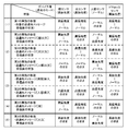
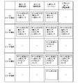
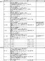
- FIG. 6 is used for the MTC device 100 to determine whether or not to perform mode switching based on the device type ID / event group information label included in the received reverse event notification message (event information). It is a figure which shows an example of event group information. In this event group information, a plurality of device type IDs (if the correspondence relation is known, it is not necessary to match the device type ID) are registered, and this device type ID is set statically / dynamically. The MTC device B 100B that has received the reverse event notification message (event information) checks whether or not the device type ID extracted from the reverse event notification message (event information) is registered in the event group information.
- FIG. 6 shows an example of event group information held by the MTC device B 100B (human sensor).
- the smoke sensor ID and the flame sensor ID are described in the event group information
- the MTC device B 100B (human sensor) holding this event group information includes the smoke sensor ID or the flame sensor ID.
- the reverse event notification message (event information)
- the mode is switched to the high priority mode (or the high priority mode is maintained as it is) and the operation is performed.
- the event group information information is registered that defines that a specific reverse event notification message (event information) is to be changed or maintained in the high priority mode.
- event group information based on, for example, a suitable operation when an event occurs.
- a high-priority event notification message (event information) is transmitted from the smoke sensor to the network side, and the reverse event notification message (event information) is broadcast in the MTC group.
- the flame sensor is operated in the high priority mode to detect the flame, and the human sensor is put in the high priority mode to quickly grasp whether there is a person remaining. It is assumed that mode transition is the optimum operation.
- the smoke sensor ID and the human sensor ID are included in the event group information held by the flame sensor, and the flame sensor ID, the human sensor ID, and the event held by the human sensor are included in the event group information held by the smoke sensor.
- the smoke sensor ID and the flame sensor ID are included in the group information held by the smoke sensor.
- step S309 and step S310 is performed according to how each MTC device 100 has event group information (whether each MTC device 100 has event group information individually, or multiple MTC devices 100 have (Whether they have the same event group information) and how the information included in the event group information is configured (the self ID of the MTC device 100 having the event group information is included in the event group information) It is possible to adopt various methods depending on whether or not.
- the basic concept of the present invention does not limit the confirmation processing method in steps S309 and S310.
- the MTC device 100 that has received the reverse event notification message can confirm whether or not the event notification message has already been transmitted from the same type of device as the own device, and the event from a different type of device from the own device. When a notification message is transmitted, it is important to be able to determine whether or not to change to the high priority mode (or keep the current mode as it is).
- FIG. 6 illustrates event group information held by the MTC device B 100B (human sensor) as described above.
- the event group information includes an ID (human sensor ID) of the human sensor itself. ) May be included.
- the MTC device B100B human sensor
- the MTC device B100B has its own device type ID (human sensor ID) in the event group information held by itself. Even if a reverse event notification message (event information) is received, a list of device type IDs of the MTC devices 100 that exceptionally operate in the high priority mode even when a reverse event notification message (event information) is received is displayed. It is possible to create common event group information by registering as information.
- the event group label information “fire” is attached and the smoke sensor It is also possible to have event group information in which the flame sensor and the human sensor are registered in common for the smoke sensor, the flame sensor, and the human sensor. Further, by making the confirmation processing in step S309 and step S310 different from the above-described operation, even if all the MTC devices 100 have common event group information, the detailed information according to the present invention will be described. There are also methods that can implement mode transition management.
- the MTC device 100 of the MTC group when receiving the reverse event notification message (event information), stores the device type ID (for example, smoke sensor) stored in the reverse event notification message (event information) (see FIG. 5). 4 step S311: storing event information).
- the stored event information is not transmitted when the MTC device 100 receives another reverse event notification message (event information (for example, human sensor ID)) from the MME 120 again (high priority). This parameter is used as a parameter for determining that the mode does not switch to the priority mode.
- the MTC device A 100A detects an event and transmits an event notification message (event information) with a high priority
- the MTC device 100 belonging to the same MTC group as the MTC device A 100A A reverse event notification message (event information) with the species ID “smoke sensor” is received.
- the MTC device B100B (smoke sensor) of the same device type as the MTC device A100A shifts from the high priority mode to the normal mode, and the reverse event notification message (event information) with the device type ID “smoke sensor”. Is stored.
- the MTC device B 100B human sensor
- the MTC device 100 in the MTC group has a device type ID.
- the reverse event notification message (event information) of “human sensor” is received following the reverse event notification message (event information) of device type ID “smoke sensor”.
- the MTC device A 100A stores a reverse event notification message (event information) in which the device type ID received earlier is “smoke sensor”, and uses the stored information (reception history) as a parameter.
- the mode does not change from the normal mode to the high priority mode, and the high priority event notification message (event information) is not transmitted again.
- the MTC device 100 that has once transited from the high priority mode to the normal mode at the same event (for example, a fire occurrence) can be controlled so as not to return to the high priority mode again.
- the parameter serving as a determination factor for switching the mode may be information other than the device type ID indicating the type of the MTC device 100.
- event information storage step from step S309 to the self device type ID confirmation step to step S311 may be performed in any order.
- the MTC device B 100B detects an event (for example, the presence of a person) (step S313 in FIG. 4: event detection).
- the MTC device B 100B that has detected the event confirms the data transmission mode when the event is detected, and notifies the MTC server 150 according to the transmission mode.
- the MTC device B 100B notifies the MTC server 150 of an event notification message storing the detected event information and the like (see FIG. Step S314 of 4: Event notification message (event information) @ device B).
- step S314 when the MTC device B 100B transmits in the normal mode instead of the high priority mode, the event notification message (event transmission) (dotted line portion) in step S314 is notified in the normal mode or is not performed, and is sent to the MTC server 150. Sensing data is transmitted (step S315 of FIG. 4: acquisition data transmission). Note that the event notification message in step S314 and the acquisition data transmission in step S315 may be performed sequentially or simultaneously.
- the MTC device A 100A that first transmitted the event notification message (event information) also receives the reverse event notification message (event information) and follows the reverse event notification message (event information) as shown in FIG. Is switched to the normal mode (step S306 in FIG. 4: mode switching), and the fact that the reverse event notification message (event information) has been received is stored (step S307 in FIG. 4: storage of event information).
- the MTC device A 100A transmits sensing data in the normal mode (step S316 in FIG. 4: acquisition data transmission).
- the acquisition data transmission in step S316 in FIG. 4 can be performed at an arbitrary timing after transmission of the event notification message (event information) @device A in step S303.
- the MTC device A 100A that first transmitted the event notification message (event information) performs the mode transition from the high priority mode to the normal mode by receiving the reverse event notification message (event information). Immediately after transmitting the event notification message (event information) in the high priority mode, the mode may be shifted to the normal mode by itself, or the MTC device A 100A that transmitted the event notification message (event information) is high as it is. The notification in the priority mode may be continuously performed.
- the MTC device 100 (for example, a flame sensor) that has normally notified the MTC server 150 with an event notification message with a high priority when an event is detected, for example, after a certain time (for example, with a reverse event notification message)
- the MTC device 100 receives a message transmitted from the MME 120 and the MTC server 150 (for example, a NAS message)
- the normal mode can be returned to the high priority mode.
- the MTC device 100 for example, a human sensor
- the normal mode can be changed to the high priority mode). As a result, even after the end of one event, the normal operation can be restored (not shown in FIG. 3).
- FIG. 8 is a diagram illustrating an example of the configuration of the MTC device 100 according to the second embodiment of the present invention.
- the MTC device 100 is connected to a communication system (for example, E-UTRAN or UTRAN) to perform communication processing in the lower layer and packet communication processing such as IP in the upper layer, received message Is the reverse event notification message, the event information stored in the received reverse event notification message is stored, and the device type ID stored in the reverse event notification message is the device type ID of the MTC device 100 itself
- the reverse event notification message processing unit 502 for checking whether the device type ID stored in the reverse event notification message is registered in the held event group information, and the reverse event notification message
- a transmission mode control unit 504 for confirming the current transmission mode, holding information used for confirming the transmission mode, and switching the transmission mode of the MTC device 100, and a specific event (monitored by the MTC device 100)
- An event detection unit 505 that detects an event
- an event notification message processing unit 503 that determines whether to send a high priority message when an event is detected.
- the transmission mode control unit 504 can be omitted.
- other functional units may be omitted when the above functional units are included in one functional unit.
- the event notification message processing unit 503 performs a function of storing event information stored in the received reverse event notification message, and determines whether or not to send a high priority message when an event is detected. The function to be performed may be separated.
- a normal mode in which sensing data detected by a sensor for detecting the occurrence of a specific event is transmitted with normal priority, or by a sensor Control to operate in the transmission mode of either the normal mode or the high priority mode that transmits a higher priority than the normal mode priority event notification message that notifies that the occurrence of a specific event has been detected A function as an operation mode control unit, a function as a transmission unit that transmits an event notification message in a high priority mode or a transmission of sensing data in a normal mode, and notifies the occurrence of a specific event to a network node Send event notification message to any communication node A message transmitted from a received network node as a response to an event notification message notified by an arbitrary communication node is received, and a message instructing to change the transmission mode to the normal mode or to maintain the normal mode is received.
- FIG. 9A is a flowchart illustrating an example of a processing flow of the MTC device 100 that performs transmission processing to the MTC server 150 in the normal mode or the high priority mode when an event is detected in the second exemplary embodiment of the present invention.
- FIG. 9B is a flowchart illustrating an example of a processing flow of the MTC device 100 that has received the reverse event notification message from the network side (for example, the MME 120) in the second exemplary embodiment of the present invention.
- the MTC device 100 establishes a PDN connection and an EPS bearer with the PGW 140 in order to communicate with the MTC server 150 (step S601 in FIG. 9A).
- the MTC device 100 detects an event with the event detection unit 505 (step S602 in FIG. 9A).
- the detection of the event includes, for example, smoke detection for a smoke sensor, flame detection for a flame sensor, and person detection for a human sensor.
- the MTC device 100 acquires information on the transmission mode (step S603 in FIG. 9A), and the event notification message determination unit 503 determines whether to transmit to the MTC server 150 with a high priority message ( Step S604 in FIG. 9A).
- the MTC device 100 uses the communication processing unit 501, for example, an event flag (for example, smoke generation), sensing data, A device type ID is generated (step S605 in FIG. 9A), and an event notification message (event information) @device A storing the event information is transmitted to the MTC server 150 through the communication system (step S606 in FIG. 9A).
- an event flag for example, smoke generation
- sensing data for example, sensing data
- a device type ID is generated
- an event notification message (event information) @device A storing the event information is transmitted to the MTC server 150 through the communication system (step S606 in FIG. 9A).
- the MTC device 100 when the MTC device 100 to which “Time Controlled” is applied accesses outside the allocated time, the MTC device 100 detects an event to be notified in the high priority mode. If the network side (for example, the MME 120) can determine, the MTC device 100 does not need to store the event flag in the event notification message (event information) @device A. If the network side can confirm that the MTC device 100 has detected an event using means other than those described above, the event flag may be omitted in the same manner.
- the network side for example, the MME 120
- the MTC device 100 does not need to store the event flag in the event notification message (event information) @device A. If the network side can confirm that the MTC device 100 has detected an event using means other than those described above, the event flag may be omitted in the same manner.
- the type of the MTC device 100 is derived from a part of the bit string indicating the device type (for example, the upper or lower bits) in the device ID, and the type of the MTC device 100 is set on the network side. If the device type ID can be identified, it is not necessary to store the device type ID.
- the MTC device 100 performs the event notification message as usual.
- Event information @Device A and the acquired sensing data are transmitted from the communication processing unit 501 (step S607 in FIG. 9).
- the MTC device 100 may receive a message (for example, a NAS message) after a certain time (for example, a lifetime value notified by a reverse event notification message) or transmitted from the MME 120 or the MTC server 150. ) May be performed to return from the high priority mode to the normal mode, or from the normal mode to the high priority mode (not shown in FIG. 9A).
- a message for example, a NAS message
- a certain time for example, a lifetime value notified by a reverse event notification message
- the MTC device 100 establishes a PDN connection and an EPS bearer with the PGW 140 in order to communicate with the MTC server 150 (step S701 in FIG. 9B).
- the reverse event notification message processing unit 502 determines whether the received message is a reverse event notification message (event information) (step in FIG. 9B). S702). If it is determined that the message is not a reverse event notification message (event information), another process suitable for the message is performed (not shown in FIG. 9B).
- the MTC device 100 extracts the device type ID from the reverse event notification message (event information), and stores the same device type ID. In order to specify the case where (event information) is received again, the extracted device type ID is stored in the reverse event notification message processing unit 502 (step S703 in FIG. 9B).
- the reverse event notification message processing unit 502 checks whether the device ID / device type ID of the MTC device 100 and the device type ID stored in the reverse event notification message (event information) match. (Step S705 in FIG. 9B). If the device ID / device type ID of the MTC device 100 and the device type ID stored in the reverse event notification message (event information) match, an event notification message has already been sent from the MTC device 100 of the same type as the own device. Since it can be determined that the data is being transmitted, the MTC device 100 operates in the normal mode (step S706 in FIG. 9B). In step S706, when the MTC device is in the high priority mode, the transmission mode control unit 504 transits to the normal mode. When the MTC device is in the normal mode, the normal mode is maintained as it is.
- the reverse event notification message processing unit 502 performs the reverse event notification message.
- Event group information corresponding to the event group information label included in (event information) is read (step S707 in FIG. 9B), and the device type ID extracted from the reverse event notification message (event information) is registered in the event group information. It is confirmed whether or not (step S708 in FIG. 9B).
- the received reverse event notification message is a reverse event notification message (event) related to an event not involving the MTC device 100.
- the MTC device 100 ends the process.
- the MTC device 100 instead of holding the event group information in which the list of device type IDs are registered in the MTC device 100, it is also possible to hold information indicating whether or not the own device type and its label are associated, In this case, the MTC device 100 only needs to confirm whether or not “the own device type and the label name (for example,“ fire ”) are associated with each other in step S708.
- the received reverse event notification message is the reverse of the event related to the MTC device 100. It can be determined that this is an event notification message (event information).
- the MTC device 100 confirms the device type ID stored in the reverse event notification message processing unit 502, and the reverse event notification message (event information) for the event notification message (event information) transmitted from the MTC device 100 of the same type. It is determined whether or not (event information) has already been received (step S709 in FIG. 9B).
- step S710 when the MTC device 100 is in the high priority mode, the transmission mode control unit 504 maintains the high priority mode as it is, and when the MTC device is in the normal mode, the mode is changed to the high priority mode. To do.
- the transmission mode determined in this way is referred to in the transmission mode confirmation process (step S603 in FIG. 9A) illustrated in FIG. 9A.
- the timing for confirming the match with the own device type ID in step S705 the timing for confirming whether the device type ID extracted from the reverse event notification message (event information) in step S708 is registered in the event group information, The timing for confirming whether the device type has already received the reverse event notification message (event information) in step S709 may be different in order.
- FIG. 10 is a diagram illustrating an example of the configuration of the MME 120 according to the second embodiment of the present invention.
- the MME 120 performs communication processing on a communication system (for example, E-UTRAN or UTRAN), and performs a communication processing unit 801 that performs packet communication processing such as IP.
- the received message has been sent with high priority.
- the event notification message processing unit 803 that acquires the event information and stores the acquired event information, reception of a redundant event notification message by the same event or an event caused by the event
- at least a reverse event notification message processing unit 802 that determines whether to transmit a reverse event notification message that stores event information acquired from the event notification message is broadcast.
- the reverse event notification message processing unit 802 has the function of the event notification message processing unit 803, the event notification message processing unit 803 can be omitted.
- other functional units may be omitted when the above functional units are included in one functional unit.
- a function as a reception unit that receives an event notification message for notifying that the occurrence of a specific event has been detected from the MTC device 100 by the operation of each of the above-described components in the MME 120, and a response to the event notification message As a message creation unit for creating a message for instructing to change the transmission mode to the normal mode or to maintain the normal mode, and a function as a message transmission unit for sending the message to the MTC device 100. Yes.
- FIG. 11 is a flowchart illustrating an example of a processing flow of the MME 120 according to the second embodiment of this invention.
- the MME 120 receives the message transmitted from the MTC device A 100A, and the event notification message processing unit 803 determines that this message is a high-priority event notification message (event information) @device A (see FIG. 11 step S901). Note that the MME 120 may refer to the event flag field of the event notification message (event information) @device A when determining that the event notification message (event information) @device A.
- the MME 120 acquires event information from the received event notification message (event information) @ device A in the event notification message processing unit 803 (step S902 in FIG. 11). Then, the MME 120 sends a reverse event notification message (event information) to the MTC device 100 of the MTC group in order to suppress transmission of a redundant event notification message due to the same event or an event caused by the event that caused the event.
- the reverse event notification message processing unit 802 determines whether to transmit (step S903 in FIG. 11). Note that when determining whether to transmit a reverse event notification message (event information) (or which label is added to the reverse event notification message to request an operation in the high priority mode), a reverse event notification is required. The determination may be made using event group information held in the message processing unit 802. Further, the information (for example, subscription data) of the MTC device 100 may be inquired to the HLR / HSS 125 for determination.
- the MME 120 sends the reverse event notification message (event information) containing the device type ID acquired from the event notification message (event information) @ device A to the MTC. Broadcast to all MTC devices (including the MTC device B 100B) of the MTC group to which the device A 100A belongs (step S904 in FIG. 11). Note that the MME 120 determines whether the MTC device A 100A belongs to the MTC group as an event notification message (event information) @ a group ID (not shown in FIG. 5A) stored in the device A, an HSS 125, or the like. The subscription data held by may be used.
- the MME 120 transmits a reverse event notification message (event information)
- the MME 120 receives the event notification message (event information) @device A again with the device type ID extracted from the event notification message (event information) @device A.
- the reverse event notification message processing unit 802 preferably stores the reverse event notification message (event information) as a parameter used when determining whether to transmit the reverse event notification message (event information).
- the device type ID extracted from the event notification message (event information) @device A may be other than the ID for identifying the type of the MTC device 100, but as described above, each MTC device 100 It must be related to the information registered in the event group information to be held.
- the MME 120 when adding an event group information label to the reverse event notification message (event information), the MME 120 specifies a predetermined identification for an event notification message (for example, a smoke sensor or a flame sensor) from a specific device. Event group information to be added from other information such as event information or sensing data included in the event notification message.
- the label name may be determined.
- a reverse event notification message is transmitted with an event group information label (for example, “fire”) added in response to an event notification message (event information) received from a certain MTC device 100 (for example, a smoke sensor)
- event notification message event information
- a certain MTC device 100 for example, a smoke sensor
- event notification message event information
- the same label name for example, “fire”
- the MME 120 releases information held by the MTC device 100 or the MME 120 after a certain period of time or based on specifications, registration information, setting information, and the like set in advance by the MTC server 150 / MTC user 160.
- a NAS message the normalization of the transmission mode of the MTC device 100 (from the high priority mode to the normal mode, or from the normal mode to the high priority mode)) may be transmitted (see FIG. 11). Not shown).
- the MME 120 transmits the reverse event notification message (event information), but the MTC server 150 can also transmit the reverse event notification message (event information).
- the configuration of the MTC server 150 when the MTC server 150 transmits a reverse event notification message (event information) is the same as the configuration of the MME 120 illustrated in FIG. Yes, the description is omitted here.
- the processing flow of the MTC server 150 is the same as the processing flow of the MME 120 illustrated in FIG. 10 (that is, the processing flow illustrated in FIG. 11). Therefore, the description is omitted here.
- FIG. 12 is a diagram illustrating an example of the arrangement of the MTC devices 100 in order to describe specific examples according to the first and second embodiments of the present invention.
- FIG. 12 shows a state in which a large number of various MTC devices 100 (smoke sensor, flame sensor, human sensor, gas sensor, water sensor, water meter sensor, earthquake sensor, door lock sensor, etc.) are arranged in the MTC group. It is schematically illustrated.
- a large number of MTC devices 100 are arranged in one facility, for example, to monitor events (accidents, disasters, etc.) that may occur in the facility.
- the present invention will focus on two smoke sensors, two flame sensors, two human sensors, one door lock sensor, and one water sensor among many MTC devices 100 in the same MTC group. The operation according to the above will be specifically described.
- the smoke sensor normally operates in a high priority mode, and is configured to transmit a high priority event notification message when the occurrence of smoke is detected.
- the flame sensor normally operates in a high priority mode, and is configured to transmit a high priority event notification message when the occurrence of a flame is detected (detection of heat).
- the human sensor normally operates in the normal mode and is configured to transmit information on the presence / absence of a person in the normal mode as sensing data.
- the door lock sensor normally operates in a high priority mode, and is configured to transmit a high priority event notification message when detecting the unlocking of the locked door.
- the water meter sensor normally operates in the normal mode and is configured to transmit the value of the water meter (meter reading value) in the normal mode as sensing data.
- ⁇ (1) in FIG. 13> for example, when a smoke sensor detects the occurrence of smoke and transmits an event notification message to the MTC server 150, the MME 120 reverses to all the MTC devices 100 in the MTC group. An event notification message is sent.
- the MTC device 100 that receives the reverse event notification message transitions to the normal mode (mainly maintained in the normal mode). Specifically, as illustrated in FIG. 13 (1), the smoke sensor, the flame sensor, and the door lock sensor transition from the high priority mode to the normal mode, and the human sensor continues to maintain the normal mode. . In addition, all other MTC devices 100 (for example, an earthquake sensor, a water sensor, etc.) are also controlled to operate in the normal mode.
- a smoke sensor detects the occurrence of smoke and transmits an event notification message (event information) to the MTC server 150
- all of the MTC groups in the MTC group are transmitted.
- the reverse event notification message (event information) is transmitted to the MTC device 100.
- all the MTC devices 100 in the MTC group receive the reverse event notification message [smoke
- the smoke sensor grasps that the event notification message (event information) is transmitted from the same device type, and shifts to the normal mode.
- the flame sensor grasps that an event notification message (event information) has been transmitted from a different device type, and maintains the high priority mode as it is.
- the human sensor transitions from the normal mode to the high priority mode by receiving a reverse event notification message (event information) including the label name “fire”. Further, the door lock sensor grasps that it is a reverse event notification message (event information) that is not related to its own device, and maintains the high priority mode as it is.
- a flame sensor detects the occurrence of a flame and transmits an event notification message (event information) to the MTC server 150
- a reverse event notification message (event information) is sent from the MME 120 to all the MTC devices 100 in the MTC group. Is sent. In this case, all the MTC devices 100 in the MTC group receive the reverse event notification message [flame
- the flame sensor grasps that the event notification message has been transmitted from the same device type, and shifts to the normal mode.
- the smoke sensor is making a transition to the normal mode by receiving a reverse event notification message (ie, reverse event notification message [smoke
- a reverse event notification message ie, reverse event notification message [smoke
- the human sensor has already made a transition to the high priority mode by receiving a reverse event notification message of an event caused by the same event (fire occurrence) (ie, reverse event notification message [smoke
- the door lock sensor grasps that it is a reverse event notification message not related to the own device, and maintains the high priority mode as it is.
- a reverse event notification message (event information) is transmitted from the MME 120 to all the MTC devices 100 in the MTC group.
- all the MTC devices 100 in the MTC group receive the reverse event notification message [human feeling
- the human sensor grasps that the event notification message is transmitted from the same device type, and shifts to the normal mode.
- the smoke sensor and the flame sensor have a reverse event notification message of an event caused by the same event (fire occurrence) (that is, a reverse event notification message [smoke
- the event group information (flame sensor) of the label “fire” is displayed on the smoke sensor.
- the sensor type device type ID of the human sensor are registered), and the event group information of the label name “fire” is registered in the flame sensor (the device type ID of the smoke sensor and human sensor is registered).
- the human sensor may be provided with event group information (the device type ID of the flame sensor and smoke sensor is registered) with the label name “fire”.
- the event group information with the label name “fire” is not provided, or the label name for which the device type ID is not registered. Have event group information for "fire”.
- event group information that differs depending on the individual device type is provided, but as another method, it is common to all MTC devices 100. It is also possible to have (identical) event group information.
- event group information in this case, for example, in the process of step S708 in FIG. 9B, in addition to checking whether the device type ID included in the reverse event notification message (event information) is included in the event group information, By confirming whether the device type ID is included in the event group information, the operation according to the present invention can be realized. Also in this case, the event group information with the label name “fire” may not be provided in the unrelated MTC device 100 such as a door lock sensor.
- the human sensor detects the reverse event notification message including the device type ID of the smoke sensor ( When the event information is received, the mode is changed to the high priority mode, but when the reverse event notification message (event information) including the flame sensor device type ID is received, the normal mode is maintained as it is. It becomes possible. Note that when such a state is not assumed (the MTC device 100 having the associated label is used regardless of the device type MTC device 100 that transmits the event notification message for a specific event).
- the MME 120 sends all the MTC devices 100 in the MTC group.
- a reverse event notification message is transmitted.
- all the MTC devices 100 in the MTC group receive a reverse event notification message [unlocking
- a reverse event notification message including both the device type ID and the event group information label (label name) as event information is transmitted. It has been broken. However, the reverse event notification message including only the device type ID may be transmitted as a configuration in which the event group information label (label name) is not used and detailed setting by the event group information is not performed. .
- the mode transition instruction to the normal mode performed by the reverse event notification message in the first embodiment is performed only for the same type of MTC device as the MTC device 100 that transmitted the event notification message. It can be said that there is.
- the processing in steps S707 to S709 is not performed in the operation of FIG. 9B (operation in the second exemplary embodiment of the present invention).
- the reverse event notification message including the device type ID “smoke sensor” is transmitted from the MME 120 to all the MTC devices 100 in the MTC group. (Event information) is transmitted.
- all the MTC devices 100 in the MTC group receive the reverse event notification message including the device type ID “smoke sensor”. As illustrated in FIG. Only the MTC device (that is, all smoke sensors) of the same type as the device type ID included in the message performs mode transition (transition to normal mode).
- a smoke sensor detects the occurrence of smoke and transmits an event notification message to the MTC server 150
- a reverse event notification message including the label name “fire” is transmitted from the MME 120 to all the MTC devices 100 in the MTC group. Is done.
- the human sensor has information indicating that its own device type is associated with the label name “fire”.
- the human sensor has the event group information of the label name “fire”, as shown in the figure, the reverse event notification message including the label name “fire” is shown.
- the information holding method is not limited as long as the information can specify that mode transition is performed at the time of reception.
- All the MTC devices 100 in the MTC group receive the reverse event notification message [fire].
- the MTC devices 100 such as a smoke sensor, a flame sensor, and a door lock sensor are not associated with the label name “fire”. No mode transition is performed.
- the human sensor is associated with the label name “fire”, and performs mode transition (transition to high priority mode) upon reception of the reverse event notification message [fire].
- the mode of MTC device 100 other than a human sensor changes to high priority mode. Therefore, transmission of the event notification message from the MTC device 100 cannot be suppressed.
- the transmission mode of the MTC device 100 for example, a human sensor
- the MTC device 100 normally operates in the normal mode can be changed to the high priority mode. Useful in terms. In other words, the MTC device 100 (human sensor) that normally operates in the normal mode can be quickly shifted to the high priority mode as necessary.
- the event notification message notified by the MTC device 100 and the reverse event notification message transmitted by the MME 120 are both exchanged on the C plane, but the event notified by the MTC device 100
- the notification message is a U plane
- the reverse event notification message is a C plane used by a network device (for example, the MME 120, the MTC server 150, or the PGW 140).
- the message in the MTC service is basically based on the specifications, registration information, and setting information of the MTC service that is statically or dynamically set by the operator of the communication system, the MTC server 150, and the MTC user 160.
- the MTC device 100 When the event is set to be exchanged on the U plane, the MTC device 100 that has detected the event (for example, smoke generation) notifies the PGW 140 / MTC server 150 of an event notification message using the U plane.
- the network device (for example, the PGW 140 / MTC server 150) wants to transmit a reverse event notification message, which is a response to the event notification message, using the U-plane based on the specifications, registration information, and setting information of the MTC service.
- the reverse event notification message must be transmitted via the MME 120 (for example, the MME 120 uses the event information (for example, device ID / device type ID) stored in the event notification message to manage the MTC device 100). Information has to be updated).
- the event information for example, device ID / device type ID
- FIG. 15 shows an example of system operation according to the third exemplary embodiment of the present invention (high-priority event due to the same event transmitted from a plurality of MTC devices 100 or an event caused by the event that caused the event) It is a sequence diagram for demonstrating the transmission suppression method of a notification message.
- FIG. 15 shows an example of a processing sequence in the system configuration shown in FIG.
- the characteristics of the MTC device 100 are the same as the characteristics of the second embodiment of the present invention, and the description thereof is omitted here.
- Steps S321 to S322 are the same as Steps S301 to S302 (see FIG. 4) in the second embodiment of the present invention, and thus description thereof is omitted here.
- the MTC device A 100A notifies the MTC server 150 of an event notification message (event information) storing the detected event information (for example, smoke sensor ID) on the U plane (step S323: event notification message (event Information) @ Device A). That is, the event notification message (event information) @device A notified from the MTC device A 100A is transferred in the order of eNB 110, SGW 130, PGW 140, and MTC server 150.
- event notification message (event information) @device A notified from the MTC device A 100A is transferred in the order of eNB 110, SGW 130, PGW 140, and MTC server 150.
- the MTC server 150 is the notification destination of the event notification message (event information), but specifications, registration information, and setting information set by the operator of the communication system, the MTC server 150, and the MTC user 160
- the destination of the event notification message may be another network device (for example, PGW 140).
- the MTC server 150 extracts event information from the received event notification message (event information) and stores it in the reverse event notification message. Then, the MTC server 150 is caused by the same event (for example, the occurrence of smoke) or the event (for example, the occurrence of flame) caused by the event (for example, the occurrence of fire) that caused the event (for example, the occurrence of smoke). In order to suppress transmission of the event notification message, a reverse event notification message is transmitted to the MME 120. Subsequently, the MME 120 broadcasts a reverse event notification message to the MTC devices 100 belonging to the MTC group using the C plane (step S324: reverse event notification message (event information)).
- event information for example, the occurrence of smoke
- the MTC server 150 broadcasts a reverse event notification message to the MTC devices 100 belonging to the MTC group using the C plane (step S324: reverse event notification message (event information)).
- the MME 120 generates the reverse event notification message here, other network devices (for example, the MTC server 150 and the PGW 140 may generate them. In that case, the network devices other than the MME 120 (the MTC server 150 and the PGW 140). ) May be broadcast.
- the MME 120 that has transmitted the reverse event notification message extracts the event information (for example, device ID) stored in the reverse event notification message, and stores it for use in determining whether to broadcast the reverse event notification message again.
- Step S325 Store event information. Since step S326 and subsequent steps are the same as step S306 and subsequent steps in the second embodiment of the present invention, description thereof is omitted here.
- the event notification message notified by the MTC device 100 is the U plane
- the reverse event notification message transmitted from the network device is C.
- the network device for example, the PGW 140 and the MTC server 150
- the reverse event notification message is transmitted (for example, the MME 120 must update the management information of the MTC device 100 using the event information (for example, device ID / device type ID) stored in the event notification message. Goodbye It is possible to correspond to have the case).
- the event notification message notified by the MTC device 100 is the C plane
- the reverse event notification message transmitted from the network device is the U plane.
- the message in the MTC service is basically based on the specification, registration information, and setting information of the MTC service that is statically or dynamically set by the operator of the communication system, the MTC server 150, and the MTC user 160. Assume that the MTC device 100 detects an event (for example, smoke generation) in an environment set to be transmitted using a U-plane.
- the MTC device 100 notifies the event notification message to the PGW 140 / MTC server 150 using the U-plane, but the MME 120 is accompanied by information necessary for management of the MTC device 100 (for example, the MTC device 100 Is a movable smoke sensor (for example, a mobile robot capable of detecting the occurrence of smoke), in addition to the event information, the MTC service 100 adds the position information of the MTC device 100.
- the MTC device 100 Is a movable smoke sensor (for example, a mobile robot capable of detecting the occurrence of smoke)
- the MTC service 100 adds the position information of the MTC device 100.
- MTC service for notifying event information (for example, when the MTC device 100 is mounted in a car or the like, and is a service that transmits location information when an event is detected), an operator of the communication system, an MTC server in advance 150, set by MTC user 160 That specification, based on the registration information and setup information, there is a case of notifying an event notification message by using the C-plane is determined in MTC device 100.
- FIG. 16 shows an example of system operation according to the fourth exemplary embodiment of the present invention (high-priority event due to the same event transmitted from a plurality of MTC devices 100 or an event caused by the event that caused the event). It is a sequence diagram for demonstrating the transmission suppression method of a notification message.
- FIG. 16 shows an example of a processing sequence in the system configuration shown in FIG.
- the characteristics of the MTC device 100 are the same as the characteristics of the second embodiment of the present invention, and the description thereof is omitted here.
- Steps S341 to S342 are the same as Steps S301 to S302 (see FIG. 4) in the second embodiment of the present invention, and thus description thereof is omitted here.
- the MTC device A 100A notifies the MME 120 of an event notification message (event information) storing the detected event information (for example, smoke sensor ID) on the C plane (step S343: event notification message (event information)).
- event notification message for example, smoke sensor ID
- the MME 120 receives an event notification message (event information) @device A from the MTC device A 100A, extracts necessary information (for example, location information and device ID of the MTC device A 100A), and performs management processing of the MTC device A 100A, for example.
- event information for example, location information and device ID of the MTC device A 100A
- management processing for example.
- update of context information of MTC device A 100A, update of position information, etc. is performed (step S344: device A management process).
- the MME 120 extracts the event notification message (event information) @event information (for example, device ID or device type ID) stored in the device A, and is used when determining whether to broadcast the reverse event notification message again. (Step S345: storage of event information).
- the MME 120 transfers the received event notification message (event information) to the MTC server 150 (step S346).
- the MME 120 forwards the received event notification message (event information) @device A as it is based on the specification, registration information and setting information set by the operator of the communication system, the MTC server 150 and the MTC user 160, or Only necessary information (for example, event information) is transmitted to the MTC server 150.
- the MTC server 150 is the notification destination of the event notification message (event information), but specifications, registration information, and setting information set by the operator of the communication system, the MTC server 150, and the MTC user 160
- the destination of the event notification message (event information) may be another network device (for example, PGW 140).
- the device A management process in step S344 to the event notification message (event information) @device A transfer process in step S346 may be performed in any order.
- the MTC server 150 extracts event information from the received event notification message (event information) and stores it in the reverse event notification message. Then, the MTC server 150 is caused by the same event (for example, the occurrence of smoke) or the event (for example, the occurrence of flame) caused by the event (for example, the occurrence of fire) that caused the event (for example, the occurrence of smoke).
- a reverse event notification message (event information) is broadcast to the MTC device 100 belonging to the MTC group using the U plane (step S347: reverse event notification message (event information)). Since step S348 and subsequent steps are the same as step S306 and subsequent steps in the second embodiment of the present invention, description thereof is omitted here.
- the event notification message notified by the MTC device 100 is the C plane
- the reverse event notification message transmitted from the network device is the U plane.
- the MTC device 100 has to transmit an event notification message via the MME 120 (C plane) in an environment in which messages in the MTC service are basically set to be transmitted using the U plane.
- the MME 120 has to update the management information of the MTC device 100 using the event information (for example, device ID / device type ID) stored in the event notification message and the location information of the MTC device 100) To deal with It can be.
- the event notification message notified by the MTC device 100 is the U plane
- the reverse event notification message transmitted from the network device is also the U plane.
- the event notification message (event information) notified from the MTC device 100 and the reverse event notification message (event information) transmitted from the network device are both exchanged on the U plane. The case will be described.
- all messages in the MTC service are based on the specifications, registration information, and setting information of the MTC service that is statically or dynamically set by the operator of the communication system, the MTC server 150, and the MTC user 160.
- This environment is set to be transmitted using the U-plane. That is, the event notification message (event information) @device A notified from the MTC device A 100A is transferred in the order of eNB 110, SGW 130, PGW 140, and MTC server 150, and the reverse event notification message (event information) transmitted from the MTC server 150. ) Are transferred in the order of PGW 140, SGW 130, eNB 110, and MTC device 100. That is, the MTC service messages are exchanged without going through the MME 120.
- all messages in the MTC service are all application information except for messages for updating the location information of the MTC device 100 (for example, TAU, RAU, paging, etc.). It is not necessary to exchange only the U plane for transferring user data (application information), not the C plane for managing mobility control of the MTC device 100 and UE 105, managing the PDN connection / EPS bearer, and managing QoS, etc.
- the environment that should not be used corresponds to the fifth embodiment of the present invention.
- FIG. 17 shows an example of system operation according to the sixth exemplary embodiment of the present invention (high-priority event due to the same event transmitted from a plurality of MTC devices 100 or an event caused by the event that caused the event). It is a sequence diagram for demonstrating the transmission suppression method of a notification message.
- FIG. 17 illustrates an example of a processing sequence in the system configuration illustrated in FIG.
- the characteristics of the MTC device 100 are the same as the characteristics of the second embodiment of the present invention, and the description thereof is omitted here.
- Steps S361 to S362 are the same as Steps S301 to S302 in the second embodiment of the present invention, and a description thereof will be omitted here.
- the MTC device A 100A notifies the MTC server 150 of an event notification message (event information) storing the detected event information (for example, smoke sensor ID) on the U plane (step S363: event notification message (event Information) @ Device A). That is, the event notification message (event information) @device A notified from the MTC device A 100A is transferred in the order of the eNB 110, the SGW 130, the PGW 140, and the MTC server 150.
- event notification message (event information) @device A notified from the MTC device A 100A is transferred in the order of the eNB 110, the SGW 130, the PGW 140, and the MTC server 150.
- the MTC server 150 is the notification destination of the event notification message (event information), but specifications, registration information, and setting information set by the operator of the communication system, the MTC server 150, and the MTC user 160
- the destination of the event notification message may be another network device (for example, PGW 140).
- the MTC server 150 stores the event information (for example, device ID and device type ID) of the received event notification message (event information) in the reverse event notification message, and uses the U plane to belong to the MTC group. Broadcast to 100 (step S364: reverse event notification message (event information)).
- event information for example, device ID and device type ID
- the MTC server 150 determines that the event (for example, the occurrence of a flame) caused by the same event (for example, the occurrence of smoke) or the event (for example, the occurrence of a fire) that caused the event (for example, the occurrence of smoke).
- event information for example, event information
- event information stored in the device A for example, device ID and device type ID
- step S365 storage of event information
- the event notification message notified by the MTC device 100 and the reverse event notification message transmitted by the network device both use the U plane.
- messages in the MTC service are all application information except messages (for example, TAU, RAU, paging, etc.) for updating the location information of the MTC device 100 and the like.
- the SGSN (Serving GPRS Support Node) plays the role of the MME 120 and the SGW 130 as described above, and performs corresponding processing.
- GGSN (Gateway GPRS Support Node) plays the role of the PGW 140, and performs corresponding processing.
- a PDP context is used as a logical communication path equivalent to the PDN connection.
- FIG. 18 shows an example of the configuration of the MTC communication network according to the seventh embodiment of the present invention.
- FIG. 18 differs from FIG. 1 in that an MTC device gateway 102 exists between the MTC device 100 and the eNB 110 (3G access).
- the MTC device gateway 102 has one or more communication interfaces for communicating with the 3G access 115. Further, the MTC device gateway 102 is provided with a communication interface for communicating with a plurality of MTC devices 100 (for example, a communication bus is provided, a communication interface to the bus, a communication interface such as a wired LAN, Zigbee (Zigbee) ( Wireless communication protocol such as registered trademark) and wireless LAN.
- a communication bus is provided, a communication interface to the bus, a communication interface such as a wired LAN, Zigbee (Zigbee) ( Wireless communication protocol such as registered trademark) and wireless LAN.
- Zigbee Zigbee
- Wireless communication protocol such as registered trademark
- the MTC device 100 does not have to have a communication interface for 3G access. That is, the MTC device 100 may not be able to transmit the detected event information and sensing data directly to the MTC server 150 via 3G access. Instead, event information and sensing data detected by the MTC device 100 are transmitted to the MTC device gateway 102, so that the MTC device gateway 102 performs network devices (for example, the MME 120, the PGW 140, and the MTC server 150 via 3G access). ).
- network devices for example, the MME 120, the PGW 140, and the MTC server 150 via 3G access.
- the MTC device gateway 102 collectively transmits the data acquired by the MTC device 100, so that the operator of the communication system, the MTC server 150, and the MTC user 160 do not need to manage the MTC device 100 individually. , Processing load and resources are reduced. Further, by collecting devices that communicate with 3G access in the MTC device gateway 102, for example, it is not necessary to mount an expensive 3G access communication interface on all the MTC devices 100, and costs can be reduced. Note that the sixth embodiment of the present invention can be said to be a realistic embodiment for a contractor who manages a system for monitoring apartments, buildings, apartment houses, and the like.
- the MTC device gateway 102 can confirm the priority level of data transmitted from the plurality of MTC devices 100, and the network side is congested.
- a communication system operator for example, a contract that allows preferential data transfer by concluding a charging rule for a high usage fee
- the MTC device gateway 102 While checking the priority level (for example, the network side shows The content priority level is compared with the priority level stored in the data transferred from the MTC device 100.
- a context preliminarily incorporated in the MTC device 100 or the MTC device gateway 102 for example, when the congestion level is 3). (Context in which rules such as transmission permission only for messages with priority level 3 or higher are registered) and the priority level included in application data), and by selecting the transfer data, the priority level is Only high data can be transferred to the network side (low-priority data transfer can be postponed (for example, after the congestion state is resolved)). Thereby, even when the network side congestion occurs, the MTC user 160 and the MTC server 150 can receive data preferentially collected.
- the MTC device 100 may play the role of the MTC device gateway 102.
- the load on the MTC device 100 serving as the MTC device gateway 102 will increase, and a means for distributing the load may be required.
- the load of the MTC device gateway 102 can be distributed by taking charge of each MTC device 100 of the MTC group in turn (for example, divided by time).
- the reverse event notification message is notified from the network side device (for example, eNB 110, MME 120, SGW 130, PGW 140, MTC server 150) and transmitted from the MTC device 100 before becoming congested on the network side.
- the transmission of redundant event notification messages is suppressed, and the network congestion state is avoided.
- a congestion state has already occurred on the network side, or when a congestion state has started when a certain message (for example, a PDN connection establishment request or transfer data) is received, the priority of the UE 105 or the like
- a high emergency message also called an emergency request or emergency message
- data application message
- PDN connection establishment request is sent
- additional resources U-plane (U-plane), C-plane (C-plane))
- processing capacity resources for example, processing in data transfer
- communication system entities for example, eNB 110, MME 120, SGW 130, and PGW 140
- communication resources and bandwidth resources allocated to the MTC device 100 and UE 105 and the like.
- priority levels e.g., eNB 110, MME 120, SGW 130, PGW 140, and MTC server 150
- network side entities e.g. For example, by selectively disconnecting using the priority level assigned to the UE 105 or the MTC device 100, the priority level of data to be transmitted, QCI or ARP), or controlling the establishment of a new PDN connection Reserve resources for high priority requests, messages, and applications.
- the eighth embodiment of the present invention is a realistic embodiment that can occur in an area where many MTC devices 100 and UEs 105 exist.
- the MTC device B, the MTC device D, the MTC device E, and the MTC device F in FIGS. 19 and 20 are defined in Non-Patent Document 1. It is assumed that it has the “Time tolerant” (time tolerance).
- the MTC device 100 having the “Time tolerant” function can delay the transmission timing of a message (for example, a PDN connection establishment request or data transfer) depending on a network congestion state or an operator policy.
- a message for example, a PDN connection establishment request or data transfer
- the operation of “Time tolerant” will be described with reference to FIG. FIG. 19 shows that MTC device A, MTC device B, and MTC device C have already established a PDN connection and transfer data from each MTC device 100 to the 3G access side ((A) data transfer in FIG. 19).
- Device D, MTC device E, and MTC device F are now in a state of establishing a PDN connection and trying to transfer data to the 3G access side (MTC devices A to C are connected modes, and MTC devices (D to F are states that the IDLE mode is gradually changed to the connected mode).
- a specific APN MTC device 100 For example, connected to a specific APN MTC device 100, MTC device 100 belonging to a specific MTC group, MTC device 100 belonging to a specific operator, a specific area (for example, an MTC device connected to a specific eNB 110 or MME 120), etc. )
- a specific area for example, an MTC device connected to a specific eNB 110 or MME 120
- the timing at which the network recognizes the congestion state is not limited to when a request for establishing a PDN connection of the MTC device D is received as described above, and congestion is caused by data transmitted by an MTC device that has already established a PDN connection. Is generated or is likely to occur, a transmission control message is broadcast to the area to which the target MTC device belongs.
- a transmission control message stores, for example, a value (for example, standby time) indicating how much a message (for example, a PDN connection establishment request) transmitted from the MTC device 100 is delayed.
- (C) Standby time in FIG. 19 The MTC device 100 that has received the (B) transmission control message in which the waiting time is stored confirms whether or not it has the “Time tolerant” function.
- the MTC device 100 holding the “Time tolerant” function delays the timing of the transmission message based on a value (for example, waiting time) indicated from 3G access.
- a value for example, waiting time
- the MTC device may calculate the value (wait time), and the MTC server 150 or the like.
- the value (waiting time) may be inquired to the external server.
- the MTC device 100 or the UE 105 that does not hold the “Time tolerant” function receives the (B) transmission control message, the timing of the transmission message cannot be delayed. For example, a PDN connection establishment request, application data, Emergency request, and Emergency message) are transmitted. Since the message transmitted by the MTC device 100 or the UE 105 that does not hold “Time tolerant” cannot be retransmitted after (C) the waiting time (the timing of the transmission message cannot be delayed), the priority level is It can be transmitted as a message transmitted from a high MTC device 100 or UE 105.
- the timing of the transmission message can be delayed (low priority level) MTC device 100 (“Time tolerant”).
- the resources (both C-plane and U-plane) are secured by disconnecting the PDN connection established by the MTC device 100 having the function "" ((C) sending a message after the waiting time).
- the MTC device 100 and the UE 105 that do not have the “Time tolerant” function receive the (B) transmission control message, a certain period (for example, (B) a value stored in the transmission control message (waiting time) If the MTC device 100 that holds the “Time tolerant” function can wait for the waiting time (fixed value) built in the MTC device 100 or the UE 105 in advance, the “Time tolerant” It is assumed that message transmission can be delayed for a longer time than the MTC device 100 that does not have the function.
- FIG. 20 shows an example of system operation according to the eighth embodiment of the present invention (an already established PDN connection is assigned to the UE 105, MTC device 100, network side entity (for example, eNB 110, MME 120, SGW 130, PGW 140, MTC server). 150), a request having a high priority level by disconnecting using the priority level (for example, the priority level assigned to the UE 105 or the MTC device 100, the priority level of data to be transmitted, QCI, or ARP). And a resource securing method for an application).
- FIG. 20 shows an example of a processing sequence in the system configuration shown in FIG.
- the MTC device A 100A, the MTC device B 100B, and the MTC device C 100C have already established the PDN connection and are performing data transfer (steps S1001A, S1001B, and S1001C in FIG. 20: the PDN connection has been established).
- the MTC device D100D transmits a PDN connection establishment request to the MME 120 in order to transfer data (step S1002 in FIG. 20: PDN connection establishment request).
- the network side entity Upon receiving a PDN connection establishment request, the network side entity (for example, eNB 110, MME 120, etc.) detects whether it has exceeded a permissible level (threshold) of processing capacity, for example, and detects a congestion state (requires resource reservation) (Step S1003 in FIG. 20: congestion detection).
- the network side entity detects the congestion state by receiving the PDN connection establishment request transmitted from the MTC device D100D, but the MTC device 100 that is transferring data is used.
- the MTC device 100 that is transferring data is used.
- the MME 120 detects a congestion state, but even if another entity (for example, the eNB 110, the SGW 130, the PGW 140, or the MTC server 150) detects the congestion state. Good.
- each entity may directly notify that the congestion state is occurring in the MTC device D100D, or may indirectly notify by notifying the MME 120, the eNB 110, or the like (for example, the PGW 140 is congested).
- the MME 120 is notified of the congestion state, and the MME 120 may notify the MTC device 100 of the congestion state when a PDN connection establishment request is transmitted from the MTC device D100D.
- the MME 120 that has detected the congestion state transmits a PDN connection establishment request rejection message to the MTC device D100D to notify that the PDN connection cannot be established (step S1004 in FIG. 20: PDN connection establishment request rejection).
- the eNB 110 receives a target MTC device 100 (for example, an MTC device connected to a specific APN, an MTC device that belongs to a specific MTC group, an MTC device that belongs to a specific operator, a specific area, etc.
- the transmission control message is broadcasted (for example, a MTC device connected to a specific eNB 110 or MME 120) (steps S1005 and S1006 in FIG. 20: transmission control message).
- the MME 120 may instruct the eNB 110 by the broadcast message instruction in step S1005 to determine the target MTC device 100.
- the MME 120 may query the eNB 110, the SGW 130, the PGW 140, and the MTC server 150 for instructions.
- the MME 120 instructs the eNB 110 to broadcast a message, and the eNB 110 broadcasts to the target device.
- the PGW 140 may instruct the eNB 110 to send a broadcast message, and the eNB 110 performs broadcast transmission.
- step S1004 and step S1005 may be switched. Further, step S1004 may be omitted if it is possible to notify the rejection of the PDN connection establishment request of MTC device D100D by broadcasting the transmission control message in step S1005.
- the MTC device 100 that has received the transmission control message confirms whether or not it has the “Time tolerant” function.
- the timing for transmitting the PDN connection establishment request is delayed based on the standby time stored in the transmission control message. Since the MTC device 100 that does not hold the “Time tolerant” function cannot delay the timing of the transmission message, the MTC device 100 transmits a PDN connection establishment request even when the network side is congested.
- the processing load of the communication system is reduced, and C-plane resources can be secured.
- the U-plane resource is not vacant until the data transfer of the MTC devices that have already established the PDN connection (MTC device A 100A to MTC device C 100C) is completed.
- a high-priority emergency message also called “Emergency request” or “Emergency message”
- an application message is sent from the UE 105 or the like, so that the UE 105 or the MTC device 100 having a higher priority level can be used.
- Resources both U-plane and C-plane may be required.
- the MTC device 100 is checked to determine whether or not the MTC device 100 has the “Time tolerant” function.
- a parameter for instructing that “the MTC device 100 having the“ Time tolerant ”function disconnects the established PDN connection” is stored in the transmission control message broadcast by the eNB 110. For example, after receiving a transmission control message broadcast from the eNB 110, the MTC device 100 that retains the “Time tolerant” function disconnects the established PDN connection. Further, the MTC device 100 may establish a PDN connection again after a certain time (for example, a value (for example, standby time) indicated from 3G access) from the transmission control message and perform data transfer.
- a certain time for example, a value (for example, standby time) indicated from 3G access
- FIG. 21 is a transmission control message broadcasted by the eNB 110 to the target MTC device 100 in step S1006 of FIG. 20.
- the MTC device 100 having the“ Time tolerant ”function disconnects the established PDN connection. It is a figure which shows the example of a format of a transmission control message as an example of the message structure in which the parameter which instruct
- FIG. 21 shows a header field necessary for broadcast transmission, a Time tolerant field indicating that “the MTC device 100 having the“ Time tolerant ”function disconnects the established PDN connection”, and more detailed information. It is composed of a detailed data field that stores detailed conditions (detailed data) used when determining whether to maintain / disconnect the PDN connection.
- the detailed data field includes an established PDN in addition to a conventional APN and location information (e.g., eNB ID and eNB address), a group ID for identifying an MTC group, and a PLMN ID for identifying a connected network operator.
- Data remaining amount data remaining amount value
- expected completion time expected completion time
- remaining time QCI (QoS Class Indicator) of PDN connection (EPS bearer) and ARP (Allocation A and Retention A Priority)
- Data transfer start time hereinafter, also referred to as “Before time”
- MTC feature for example, an MTC device having a “Mobile originated only” function that can only receive incoming calls defined in Non-Patent Document 1) 100
- the MTC device 100 includes a detailed determination condition stored in the detailed data field in addition to whether the MTC device 100 has the “Time tolerant” function. Can be used.
- the entity of the MTC device 100, the UE 105, or the communication system can recognize the MTC device 100 having a low priority level or a parameter indicating the application (eg, “Low priority indicator”), ““ Low It may be replaced with a parameter indicating that the MTC device 100 having the “priority” function disconnects the established PDN connection ”(may be used instead).
- a parameter indicating the application eg, “Low priority indicator”
- ““ Low It may be replaced with a parameter indicating that the MTC device 100 having the “priority” function disconnects the established PDN connection ”(may be used instead).
- MTC device 100 holding“ Time tolerant ”function and only the PDN connection established by “MTC device 100 holding“ Mobile associated only ”” is disconnected.
- the PDN connection established by the “MTC device 100 holding the“ Time tolerant ”function” or the “MTC device 100 holding the“ Mobile originated only ”function” is disconnected.
- the MTC device 100 that has the function of “Time tolerant”, establishes a PDN connection after the value (time) indicated by Before time, or In the case of the MTC device 100 that has started data transmission, it may be defined that the established PDN connection is disconnected.
- Before time may indicate a value (time), for example, “AM11: 00”.
- Before time can be specified as "MTC device that established a PDN connection within the value (time) indicated by Before time, or the time elapsed since the start of data transfer” In this case, a value (time) may be indicated, for example, “1 minute”.
- the MTC device 100 that has the function of “Time tolerant” by storing the data remaining amount (data remaining amount value) of data to be transferred in the detailed data field is transmitted by the MTC device 100. If the remaining amount of data exceeds the data remaining amount value instructed from the network side, it may be defined that the established PDN connection is disconnected. At this time, the remaining data value may indicate a value such as “1M Bytes”, for example.
- the MTC device 100 that has the “Time tolerant” function, and the expected completion time of data transmission expected by the MTC device 100 ( If the remaining time) exceeds the expected completion time (remaining time) stored in the transmission control message broadcast from the eNB 110, it may be defined that the established PDN connection is disconnected.
- the expected completion time may be a value such as “AM11: 15” and the remaining time may be “1 minute”.
- information that can be acquired from an application that indicates the time until the completion of data download may be used as the expected completion time and the remaining time.
- the MTC device 100 having the “Time tolerant” function, and the PCI connection and EPS bearer QCI used in the currently transmitted data are used.
- ARP or ARP is less than or equal to the value indicated in the detailed data field, the corresponding PDN connection may be disconnected.
- the QCI and ARP stored in the detailed data field by the communication system entity (for example, eNB 110, MME 120, SGW 130, and PGW 140) and the MTC server 150 include, for example, the context in which the subscription data and the information of the MTC device 100 are registered, charging rules, and the like It may be determined using data obtained from a PCRF (Policy and Charging Rules Function, not shown in FIG.
- PCRF Policy and Charging Rules Function
- the MME 120 obtains the subscription data of the MTC device 100 that is the transmission destination of the transmission control message from the HSS 125, derives the average QCI and ARP of the established PDN connection, and compares the current data with the current congestion state to obtain detailed data.
- the QCI or ARP stored in the field may be determined.
- the MTC device 100 uses the detailed judgment condition for disconnecting the PDN connection stored in the detailed data field as described above. For example, when the Before time is stored, the MTC device 100 uses the Before time. The MTC device 100 stores the time when the data transfer is started and the time when the PDN connection is established, or starts a timer from that time, and measures the time until the transmission control message broadcast from the eNB 110 is received. Also good.
- the MTC device 100 needs to grasp the remaining data currently being transmitted. For example, the MTC device 100 may calculate the remaining data amount by storing the total amount of data scheduled to be transmitted (for example, 50M Bytes) and the amount of transmitted data.
- the above formula is an example of a simply calculated formula, and a formula considering a packet loss rate in an actual environment may be used. Further, such an expected completion time and remaining time may be acquired from a running application.
- the MTC device 100 needs to grasp the QCI and ARP of the PDN connection currently used. For example, when the MTC device 100 establishes a PDN connection (EPS bearer) (for example, during an Attach procedure or a Bearer modification procedure), the MTC device 100 receives a QCI from an entity on the network side (for example, eNB 110, MME 120, SGW 130, PGW 140, HSS 125). Or ARP may be acquired and compared with QCI or ARP stored in a transmission control message broadcast from the network side.
- EPS bearer EPS bearer
- the MTC device 100 needs to grasp the mounted MTC feature.
- the MTC device 100 may have an MTC device 100 context, and may register all the MTC features installed in each MTC device 100 in the context.
- the MTC device 100 establishes 3G access and a PDN connection (for example, during Attach procedure)
- the MTC feature installed in the MTC device 100 may be grasped.
- the detailed data field may be omitted from the format illustrated in FIG. 21, for example.
- conventional paging and SIB System Information Block
- SIB System Information Block
- the MTC device 100 that retains the“ Time tolerant ”function is available.
- the established PDN connection will be disconnected may be notified.
- each MTC device 100 may be notified using a conventional MBMS (Multimedia Broadcast And Multi Service).
- MBMS Multimedia Broadcast And Multi Service
- the PDN connection is disconnected (step S1007 in FIG. 20: PDN connection release).
- the MTC device 100 and an entity of the communication system for example, the eNB 110, the MME 120, the SGW 130, and the PGW 140
- the previous state for example, the IP address, IMSI, IMEI, and key information of the MTC device 100
- the previous state for example, the IP address, IMSI, IMEI, and key information of the MTC device 100
- the MTC device B 100B corresponds to the MTC device 100 that has the “Time tolerant” function and has already established the PDN connection. That is, when receiving the transmission control message in step S1006, the MTC device B 100B disconnects the established PDN connection. At this time, the MTC device B 100B uses a process related to a conventional technology such as UE-initiated Detail Procedure or UE requested bearer resource modification procedure defined in Non-Patent Document 3 to disconnect the established PDN connection. May be.
- the MTC device 100 that does not hold “Time tolerant” and has established the PDN connection (corresponding to the MTC device A 100A and the MTC device C 100C in the example of FIG. 20) maintains the PDN connection as it is.
- the MTC device 100 (which corresponds to the MTC device E100E or the MTC device F100F) that has held “Time tolerant” and has not held a PDN connection and is about to transmit a message (for example, a PDN connection establishment request) from now on. As described above (for example, (D) to (E) in FIG. 19), the message transmission timing is delayed.
- Step S1008 in FIG. 20 Data transmission / PDN connection establishment request.
- the UE 105 can transmit a message.
- the resources both C-plane and U-plane
- the network side transmits data by the UE in step S1008 or establishes the PDN connection. Can accept request.
- the MTC device 100 having the “Time tolerant” function not only the MTC device 100 having the “Time tolerant” function is targeted, but the group ID of the APN and the MTC group, and the PLMN ID ( Public (Land) Mobile (Network ID), device type ID, device ID, etc. may be used in combination.
- PLMN ID Public (Land) Mobile (Network ID)
- device type ID device ID, etc.
- the MDN device 100 disconnects the PDN connection established after receiving the transmission control message.
- the communication system entity eg, eNB 110, MME 120, SGW 130, PGW 140
- the server 150 can confirm the PDN connection (“specific PDN connection”) to be disconnected from the information such as the subscription data, the context specific to the MTC device 100, and message exchange (for example, Attach procedure).
- the PDN connection may be disconnected under the initiative of an entity of the communication system (for example, eNB 110, MME 120, SGW 130, PGW 140) or MTC server 150.
- Non-Patent Document 3 a process related to a conventional technique such as PDN GW initiated bearer deactivation or MME-initiated Detach procedure defined in Non-Patent Document 3 may be used.
- an entity of a communication system for example, eNB 110, MME 120, SGW 130, PGW 140
- MTC server 150 calculates or acquires a PDN connection calculated or acquired to secure resources for UE 105 or MTC device 100 having a high priority.
- the PDN connection is established by the conditions for disconnection (for example, the MTC device 100 having the “Time tolerant” function and the MTC device 100 corresponding to the value indicated by Before time) and the stored MTC device 100.
- the PDN connections to be disconnected can be confirmed by comparing the times.
- FIG. 22 is a diagram illustrating an example of the configuration of the MTC device 100 according to the eighth embodiment of the present invention.
- an MTC device 100 is connected to a communication system (for example, E-UTRAN or UTRAN) to perform communication processing in the lower layer and packet communication processing such as IP in the upper layer, from the network side.
- a broadcast message processing unit 1120 for processing the time tolerant field and the detailed data field of the transmission control message transmitted by broadcast, and a PDN connection processing unit for maintaining / disconnecting an already established PDN connection based on the result of the broadcast message processing unit 1120 1130 at least.
- a detailed data processing unit 1140 may be provided.
- the detailed data processing unit 1140 has a function of storing the time when the data transmission is started in the MTC device 100 and a timer function.
- the detailed data processing unit 1140 may be incorporated into an existing processing unit (for example, the broadcast message processing unit 1120).
- the MTC device 100 receives a message (transmission control message) broadcast from the eNB 110 (step S1210 in FIG. 23).
- the MTC device 100 broadcasts information stored in the Time tolerant field and the detailed data field of the broadcast message (transmission control message) in order to confirm whether the MTC device 100 itself is the MTC device 100 that disconnects the PDN connection. Obtained by the message processing unit 1120 (step S1220 in FIG. 23).
- the MTC device 100 determines that it is not included in the transmission target of the received broadcast message, the MTC device 100 ends without performing any special processing.
- the MTC device 100 determines that it is included in the transmission target of the received broadcast message, it further checks whether or not a PDN connection has been established between the MTC device 100 and the communication system. (Step S1230 in FIG. 23). The details of the processing flow (the processing in step S1220 in FIG. 23) for determining whether or not the MTC device 100 is included in the broadcast message transmission target will be described later (see FIG. 24).
- the MTC device 100 When the PDN connection is not established between the MTC device 100 and the communication system, the MTC device 100 operates when the PDN connection is not established (for example, the MTC device 100 having the function of “Time tolerant” establishes the PDN connection). The request transmission timing is delayed) (step S1240 in FIG. 23), and the process ends.
- the MTC device 100 uses the PDN connection processing unit 1130, for example, UE-initiated Detach Procedure or UE defined in Non-Patent Document 3.
- the established PDN connection is disconnected using a requested bearer resource modification procedure or the like (step S1250 in FIG. 23).
- the MTC device 100 receives a message (transmission control message) broadcast from the eNB 110 (step S1210 in FIG. 24). Subsequently, the MTC device 100 confirms the Time tolerant field of the broadcast message (transmission control message) in order to confirm whether the MTC device 100 itself is the MTC device 100 that disconnects the PDN connection (step S1221 in FIG. 24). ).
- the MTC device 100 for example, information set at the time of manufacture (for example, the MTC device 100 context in which the MTC feature list is registered) or information notified from the network side during the Attach procedure (for example, the communication system) It is also possible to confirm whether or not the device itself has the “Time tolerant” function from the MTC feature set by the operator or the MTC feature set by the MTC User.
- the MTC device 100 ends without performing any special processing.
- the MTC device 100 determines that the device itself has the “Time tolerant” function, the MTC device 100 subsequently sets the value (time) of the Before time indicated in the detailed data field of the transmission control message. get.
- the MTC device 100 stores the time when the PDN connection is established, the start time of the data transfer performed by the established PDN connection, or starts the timer Suppose that the time until the transmission control message is received is measured.
- the MTC device 100 compares the value (time) of the Before time indicated in the detailed data field of the transmission control message with the value (time) stored (or measured), and determines the disconnection of the PDN connection (FIG. 24). Step S1222).
- the value (time) of Before time indicated in the detailed data field of the transmission control message is “AM11: 00”
- the value (time) stored (or measured) by the MTC device 100 is “AM10: 55”.
- the network has started communication before the value (time) determined by the network side. That is, it is determined that the subject is not included in the transmission target of the transmission control message, and as a result, the PDN connection is maintained without performing special processing.
- the format such as “1 minute ago” may be used instead of the format “AM 11:00”.
- the transmission control message indicates that communication has started after the value (time) determined by the network side.
- the established PDN connection is disconnected (steps S1230 and S1240 in FIG. 24).
- Step S1222 of FIG. 24 is Before
- the remaining data value indicated by the transmission control message> the remaining data value calculated in the MTC device is performed.
- the remaining data amount it is possible to make detailed determination conditions used for maintaining / disconnecting the PDN connection. For example, after the PDN connection is disconnected or narrowed down using Before time, it may be determined whether the PDN connection is disconnected depending on how much data is remaining in the PDN connection.
- the MTC device 100 having the Low priority indicator when a congestion state occurs on the network side, the MTC device 100 having the Low priority indicator first.
- the PDN connection established can be disconnected step by step, such as disconnecting the PDN connection established by the MTC device 100 having the “Time tolerant” function. As a result, resources can be secured in stages, and excessive disconnection of the PDN connection can be avoided.
- an entity of a communication system registers the MTC device 100 that has transmitted the PDN connection establishment request in which the Low priority indicator is stored, for example, in the MTC device context, or The above processing may be realized by grasping the information by registering it in the subscription data. Further, the communication system entity may identify the MTC device 100 having the Low priority indicator by specifying the MTC device 100 having the Low priority indicator by grasping the MTC device 100 having the Low priority indicator.
- the PDN connection to be disconnected may be determined using the Low priority indicator field instead of the Time tolerant field.
- the Low priority indicator field may be used in combination with the detailed data field.
- the eNB 110 when the MME 120 detects a congestion state, the eNB 110 first transmits an instruction to disconnect the PDN connection established by the MTC device 100 having the low priority indicator to the eNB 110, and sends a transmission control message to the target MTC device 100. Broadcast. The MTC device 100 that receives the transmission control message and has the Low priority indicator disconnects the established PDN connection.
- the MME 120 when it is determined that the resource is not sufficiently secured (for example, when the threshold value indicating the congestion state is exceeded), the MME 120 holds the Time tolerant field (for example, ““ Time tolerant ”function). )) And a detailed data field (for example, ““ Mobile Originated only ””), when the established PDN connection is disconnected, the eNB 110 is notified, and the eNB 110 broadcasts to the target MTC device 100.
- the MTC device 100 that receives the transmission control message and has the functions of “Time tolerant” and “Mobile Originated only” disconnects the established PDN connection. As a result, resources can be secured in stages, and excessive disconnection of the PDN connection can be avoided.
- MTC device B100B MTC device D100D, MTC device E100E, and MTC device F100F
- MTC device B100B MTC device D100D
- MTC device E100E MTC device E100E
- MTC device F100F MTC device F100F
- the MTC device 100 When all the MTC devices 100 have the “Time tolerant” function, it is impossible to determine whether the PDN connection is disconnected depending on whether or not the “Time tolerant” function is held.
- the disconnection of the PDN connection is determined using the determination condition stored in the detailed data field. For example, in an environment where all the MTC devices 100 have the “Time tolerant” function, the MTC device 100 has the “Time tolerant” function and also has the “Mobile Originated only” function.
- the broadcast message for disconnecting the PDN connection becomes a transmission control message for disconnecting the PDN connection established by the MTC device 100 having the function of “Mobile Originated only”.
- the transmission control message for disconnecting the established PDN connection is the MTC device 100 that meets the condition “time indicated by the transmission control message> time stored in the MTC device 100”. Becomes a transmission control message for disconnecting the PDN connection established by. Therefore, in the transmission control message broadcasted by the eNB 110, the Time tolerant field in FIG. 21 for identifying whether or not the MTC device 100 has the “Time tolerant” function can be omitted.
- the congestion state has occurred.
- a higher priority emergency message also called “Emergency request” or “Emergency message”
- an application message is sent from the UE 105 or the like to generate additional resources (both U-plane and C-plane).
- the MTC device 100 holds the “Time tolerant” function in a message broadcast from the network side, and the value (for example, “Befo” is shown in the detailed data field). Using e time "at time elapsed from the start of the data transfer shown), the maintenance / disconnection of the PDN connection is already established. As a result, it is possible to secure resources for requests and applications having a high priority level.
- the target MTC device 100 (for example, the MTC device 100 connected to a specific APN, the MTC belonging to a specific MTC group) from the network side (for example, the eNB 110, the MME 120, the SGW 130, the PGW 140, or the MTC server 150).
- the MTC device 100 belonging to a specific operator, a specific area eg, the MTC device 100 connected to a specific eNB 110 or MME 120, etc.
- the message eg, PDN
- a message for example, a reverse event notification message in the first to seventh embodiments of the present invention, from an entity on the network side (for example, eNB 110, MME 120, SGW, PGW, MTC server 150),
- a transmission control message is broadcast.
- a network-side entity eg, eNB 110, MME 120, SGW 130, PGW 140, MTC server 150
- time also called Stop time, Barring time, Backoff time, Wait time, etc.
- the MTC device 100 cannot perform message transmission such as data transmission or a PDN connection establishment request during the standby time (for example, the MTC device 100 is in a data transmission suppression mode, a restriction mode, a restriction mode, etc. from the normal mode). Mode transition). However, when an event with a high priority level is detected or an emergency occurs, message transmission is suppressed from the network side, but the MTC device 100 does not transmit data or transmit a PDN connection establishment request. It is assumed that the mode can be changed to a possible mode (for example, the normal mode). Further, this waiting time may be shared with a condition (for example, Before time) for maintaining / disconnecting the PDN connection stored in the detailed data field.
- a condition for example, Before time
- the waiting time is set to “3 minutes”, and a message (for example, a PDN connection establishment request) from a low priority level MTC device is suppressed for 3 minutes, and at the same time, the PDN connection established within 3 minutes is disconnected. You may instruct.
- the detailed data field can be omitted, and the processing load of the communication system entity, the MTC device 100, and the network traffic are reduced.
- a message from the UE 105 is a priority level B, etc.
- an entity on the network side eg, eNB 110, MME 120, SGW 130, PGW 140, MTC server 150
- a parameter indicating that “only priority level B is suppressed” is stored in the transmission control message broadcasted by the eNB 110.
- the MTC device 100 delays / stops transmission of only the priority level B message, or changes the priority level and transmits the message.
- only priority level B is suppressed may be used in combination with a parameter indicating that “the MTC device 100 belonging to MTC group A is exempt”. Moreover, you may suppress the message transmitted from the MTC device 100 using not only a priority level but the prior art, for example, Access class.
- the MTC device 100 in the above-described embodiment belongs to one MTC group, one APN, and one PLMN operator.
- APN may belong to multiple PLMN operators.
- the communication system can suppress messages transmitted from the MTC device 100 in stages. For example, a transmission control message broadcasted by an entity on the network side (for example, eNB 110, MME 120, SGW 130, PGW 140, MTC server 150), or “suppress transmission message using APN-1” in a reverse event notification message The parameter indicating is stored.
- the MTC device 100 can suppress message transmission using APN-1, but can perform message transmission using APN-2.
- the established PDN connection is disconnected as a result of using the “Time tolerant” field and the detailed data field.
- the established PDN connection may be determined to be “maintained” instead of being disconnected.
- the MTC device 100 if the MTC device 100 that holds the “Time tolerant” function and meets the conditions specified in the detailed data field has already established a PDN connection, the MTC The device 100 has disconnected the PDN connection (steps S1221, S1222, S1230, and S1250 in FIG. 24), but the PDN connection is not disconnected (maintained), and only the data transmission is controlled (for example, stop, data rate Change, data size change). As a result, U-plane resources can be secured in stages.
- the PDN connection is not disconnected, it is not necessary to establish the PDN connection again, and the processing load of the communication system entities (for example, eNB 110, MME 120, SGW 130, and PGW 140) is reduced (for example, address allocation, binding update). ).
- the communication system entities for example, eNB 110, MME 120, SGW 130, and PGW 140
- the entity of the communication system broadcasts to the target MTC device 100 to secure resources for the UE 105 and the MTC device 100 having a high priority level.
- it may be transmitted by unicast or multicast instead of broadcast.
- the MTC device D100D transmits a PDN connection establishment request to the network side (step S1002 in FIG. 20). It became congested (step S1003 in FIG. 20), and the transmission control message was transmitted to the MTC device (step S1006 in FIG. 20). That is, when the network side is in a mixed state, the transmission control message is to avoid a message (for example, a PDN connection establishment request) from the MTC device 100 having a low priority level and to disconnect an already established PDN connection. Used to request. Furthermore, the transmission control message can also be used to reject or delay another PDN connection establishment request that may be newly transmitted by the MTC device 100 that has already established a PDN connection.
- a message for example, a PDN connection establishment request
- the entity of the communication system broadcasts the transmission control message including the waiting time to the target MTC device when a congestion state is detected.
- the waiting time stored as parameter information in the transmission control message broadcast by the network side is the MTC device 100 (MTC device A100A, MTC device B100B, MTC device C100C, MTC device D100D) that has already established the PDN connection. Is used as information for instructing to delay the transmission timing of the additional PDN connection establishment message to be transmitted.
- the MTC device 100 that has received this transmission control message has already held the PDN connection that the MTC device 100 has already established, and if it is desired to newly establish another PDN connection, the PDN connection until the waiting time elapses. It is determined that transmission of the establishment request is delayed. For example, when the MTC device 100 that has already established one PDN connection is trying to newly establish one more PDN connection, a request for establishing the second PDN connection is received by receiving a transmission control message. Is delayed after the waiting time.
- the MTC device 100 that has already established the PDN connection receives a transmission control message in which the standby time is not stored, it is possible to prevent an additional PDN connection establishment request from being transmitted. For example, by storing a parameter indicating “prohibition of additional establishment” in the transmission control message, transmission of an additional PDN connection establishment request by the MTC device 100 is avoided.
- the MTC device 100 for which the PDN connection has already been established is a transmission control message in which the standby time is not stored, and parameters for the PDN connection to be added by the MTC device 100 (for example, each MTC device 100 can be established).
- a transmission control message storing a maximum number of new PDN connections or a QoS that can be assigned to an additional PDN connection is received, a PDN connection establishment request is transmitted according to this information when establishing an additional PDN connection. To do.
- the parameter information includes the maximum number of PDN connections that can be simultaneously established
- the number of PDN connections that the MTC device 100 itself wants to establish and the maximum number of PDN connections that can be established simultaneously are stored in the transmission control message.
- a new PDN connection is established after the established PDN connection is completed. That is, when the MTC device 100 that wants to establish the second PDN connection receives the parameter information indicating that the number of PDN connections that can be simultaneously established is one, communication using the established first PDN connection is performed. After finishing and disconnecting the PDN connection, a second new other PDN connection is established.
- the PDN connection is disconnected and a third new PDN connection is established.
- a new PDN connection needs to be established, it may be determined that the already established PDN connection is immediately disconnected.
- information indicating that the establishment of additional PDN connections is restricted may be included in the transmission control message. The MTC device 100 that has received this information, when establishing a new PDN connection, disconnects the already established PDN connection, and then transmits a new PDN connection establishment request.
- the MTC device 100 has to establish a plurality of PDN connections (for example, the MTC device 100 is connected to a plurality of MTC servers 150 or a plurality of APNs or a plurality of MTC users 160, and MTC users
- the bandwidth is occupied by establishing multiple PDN connections at the same time. There is an effect to prevent that.
- the waiting time Is stored the application time (for example, the maximum number of PDN connections that can be established by each MTC device 100 or the QoS that can be allocated to the additional PDN connection) by the MTC device 100 is added (for example, By using it as an effective period, resource management is performed in accordance with the network-side congestion state that changes in real time.
- the transmission control message broadcast from the network side stores the standby time (for example, “1 minute”) and indicates that “one MDN device 100 can establish one PDN connection”.
- the MTC device 100 If the MTC device 100 that has received the transmission control message transmits a new PDN connection establishment request within one minute after receiving the transmission control message, the MTC device 100 disconnects the already established PDN connection, Establish additional PDN connections. After the standby time elapses, the information indicating that “one MDN device 100 can establish one PDN connection” has passed the application time, so it is not used when establishing an additional PDN connection. It's okay.
- the MTC device 100 that has received the transmission control message storing the parameters for the PDN connection scheduled to be added, when establishing the additional PDN connection, gives up on the establishment of the additional PDN connection and maintains the already established PDN connection.
- a context held by the MTC device 100 for example, a request from the MTC server 150 or the MTC user 160, a static Information
- application specifications based on specifications.
- the information indicating that “one MDN device 100 can establish one PDN connection” may be stored in the detailed data field of the transmission control message.
- a message for notifying the parameter for the additional PDN connection to the MTC device 100 that has already established the PDN connection may be transmitted by unicast instead of broadcast.
- the MTC device 100 establishes the first PDN connection (for example, during the Attach procedure)
- the parameter for the additional PDN connection from the entity of the communication system (for example, the PDN connection that each MTC device 100 can establish).
- a transmission control message including the maximum number or QoS that can be allocated to the additional PDN connection is received.
- the MTC device 100 that has acquired the parameter information transmits a PDN connection establishment request for establishing an additional PDN connection in accordance with the acquired parameter information as described above.
- the timing at which the parameter information for the additional PDN connection is notified to the MTC device 100 is not limited to when the first PDN connection establishment request is received from the MTC device 100, and any timing after the establishment of the PDN connection has already ended The timing of That is, when the network side detects a congestion state, parameter information is notified to the MTC device 100 that has already established a PDN connection. Further, when an establishment request for an additional PDN connection transmitted by the MTC device 100 is received, a transmission control message for notifying that the establishment request has been rejected, and a transmission control message including parameter information for the additional PDN connection May be notified to the MTC device 100.
- the MTC device 100 that has already established a PDN connection and that desires to establish an additional PDN connection has already been established based on the information on the congestion state notified from the network. Release an additional PDN connection and establish an additional PDN connection.
- the MTC device 100 may wish to establish a new PDN connection and transmit data even when the network is congested. For example, the maintenance data for confirming whether the MTC device 100 is a human sensor and the sensor is not malfunctioning is different from the MTC server 150 that is the transmission destination of the sensing data actually acquired by the sensor.
- a PDN connection for establishing a PDN connection for transmitting sensed data is established only for an arbitrary period, or a PDN for connecting to the MTC server 150 when the MTC device 100 is a vending machine.
- IMS IP Multimedia Subsystem
- the network may detect a congestion state between the establishment of the first PDN connection and the establishment of the additional PDN connection.
- an additional PDN connection establishment request transmitted by the MTC device 100 is detected. Will be rejected.
- the MTC device 100 there is a case where the data transmitted through the additionally established PDN connection has a higher priority level than the data transmitted through the already established PDN connection.
- the MTC device 100 cannot establish an additional PDN connection, there is a disadvantage that data having a high priority level cannot be transmitted / received to / from the MTC device 100, the MTC server 150, the MTC user 160, and the like.
- the MTC device 100 which has already established the PDN connection releases the already established PDN connection based on the information on the congestion state notified from the network, and adds the additional PDN connection. Establish.
- FIG. 25 illustrates a ninth embodiment of the present invention.
- the MTC device 100 in the ninth embodiment of the present invention has already established one PDN connection with the network.
- the bit rate (GBR: GuaranteedGBit Rate) guaranteed by the network for the EPS bearer in a completed PDN connection is 5 Mbps.
- the MTC device 100 transmits a PDN connection establishment request in order to establish an additional PDN connection.
- GBR 5 Mbps
- the network guarantees a bit rate of 5 Mbps to the MTC device 100.
- the network does not provide a bit rate below 5 Mbps (eg, 4 Mbps) to the MTC device 100 while the MTC device 100 is allocated a 5 Mbps GBR.
- the MTC device 100 transmits a PDN connection establishment request to establish an additional PDN connection (step S2501: PDN connection establishment request).
- a PDN connectivity request message, a Service request, a Create Bearer request message, or the like defined in Non-Patent Document 3 may be used.
- step S2502 PDN connection establishment rejection response
- the MTC device 100 rejected to establish the additional PDN connection compares the priority level of the additional PDN connection with the priority level of the established PDN connection (step S2503: comparison of priority levels).
- the priority level of the PDN connection is stored in a static (static) manner for the priority level assigned to each application that can be acquired from the application layer, the policy held by the MTC device 100, and the MTC device 100 for MTC. May be acquired using information (for example, preferentially processing an application started first).
- the MTC device 100 that has determined that the priority level of the additional PDN connection is higher can check the EPS bearer of the already established PDN connection in order to check whether the additional PDN connection can be established instead of the established PDN connection.
- the assigned QoS information (such as GBR information) is compared with the QoS information (such as GBR information) necessary for the EPS bearer of the additional PDN connection (step S2504: QoS comparison).
- the MTC device 100 when comparing by GBR, as shown in FIG. 27A, when the GBR allocated to the EPS bearer of the established PDN connection is 1 Mbps, the MTC device 100 is necessary for the EPS bearer of the additional PDN connection. If the GBR is 1 Mbps or less, an additional PDN connection can be established by disconnecting the established PDN connection. At this time, if the MTC device 100 cannot establish an additional PDN connection in the prior art, but knows that the priority level of the additional PDN connection is higher than the established PDN connection, After the MTC device 100 releases the established PDN connection, the MTC device 100 establishes an additional PDN connection.
- the MTC device 100 when comparing by QCI, as shown in FIG. 27B, when the QCI of the PDN connection additionally established by the MTC device 100 matches the QCI assigned to the already established PDN connection.
- the MTC device 100 can establish an additional PDN connection by disconnecting the established PDN connection.
- the QCIs match and the GBR of the established PDN connection is larger than the GBR of the additionally established PDN connection, the MTC device 100 disconnects the established PDN connection, It may be determined that a PDN connection can be established.
- the MTC device 100 cannot establish an additional PDN connection in the prior art, but the priority level of the additional PDN connection is higher than the established PDN connection. Since the MTC device 100 releases the established PDN connection, the MTC device 100 establishes an additional PDN connection.
- the MTC device 100 may use GBR and MBR as the QoS information.
- the MTC device 100 confirms whether the GBR used in the bearer of the additionally established PDN connection is equal to or less than “GBR used in the bearer of the already established PDN connection”. In the case of “GBR used in bearer of already established PDN connection” or less, the MTC device 100 confirms the MBR similarly to the GBR.
- the MTC device 100 uses the resource secured by releasing the already established PDN connection to use the additional PDN connection. It is determined that it can be established, and the already established PDN connection is released. Then, the MTC device 100 establishes a new PDN connection.
- GBR GBR
- QCI QCI
- MBR MBR
- each PDN connection or The total QoS information allocated to the EPS bearers of each PDN connection (such as the total GBR) or both (such as the bearer case where the QCIs match) satisfy the QoS information required for the additionally established PDN connection. If so, the MTC device 100 can establish an additional PDN connection. At this time, the MTC device 100 may release all the established PDN connections, or after selecting a plurality of PDN connections that need to be released in order to secure QoS information necessary for the additional PDN connection, May be released.
- the QoS information necessary for the additional PDN connection and EPS bearer includes, for example, an application of the MTC service, a policy held by the MTC device 100, information stored statically for MTC in the MTC device 100, MTC You may acquire from the information etc. which are directly notified from the server 150 or the MTC user 160.
- Step S2503 if the QoS information (GBR information) of the additionally established EPS bearer of the PDN connection is less than or equal to the QoS information (GBR information) assigned to the EPS bearer of the already established PDN connection ( For example, when the GBR information allocated to the EPS bearer of the already established PDN connection is 5 Mbps, and the GBR information required for the EPS bearer of the additionally established PDN connection is 4 Mbps), the established PDN connection is released. (Step S2505: PDN connection release procedure). When releasing an established PDN connection, UE requested PDN disconnection procedure defined in Non-Patent Literature 3, UE-initialized procedure procedure, UE requested bearer resource modification, etc. may be used.
- the resources secured by the MTC device 100 releasing the PDN connection are allocated to other MTC devices or UEs instead of the MTC device 100.
- the MTC device 100 when the MTC device 100 releases the established PDN connection, the MTC device 100 re-uses the QoS information (GBR information) allocated to the EPS bearer of the released PDN connection in the newly established PDN connection. To notify.
- GLR information QoS information
- FIG. 28 shows that the MTC device 100 uses the UE requested PDN disconnection procedure to reuse the resource (QoS information) allocated to the EPS bearer of the PDN connection released to the network side in the newly established PDN connection. It is a format example of the message notified to a network.
- the message shown in FIG. 28 includes, in addition to the conventional PDN Disconnection Request message field, a QoS holding field for notifying other MTC devices 100 and UEs 105 not to assign QoS information (GBR information), an MTC device.
- 100 includes a retention period field that indicates a period during which QoS information is retained on the network side requested by 100.
- the MTC device 100 transmits a PDN connection establishment request (step S2506: PDN connection establishment request).
- the network side can identify the MTC device 100 that is going to establish a new PDN connection using the resources secured by releasing the PDN connection.
- the MTC device 100 may be identified using the IMSI or IMEI of the MTC device 100 stored in the PDN connection establishment request, or a new identifier exchanged during the PDN connection release procedure.
- the network that has received the PDN connection establishment request in step S2506 confirms that the network is the MTC device 100 that is newly trying to establish a PDN connection using the resources secured by releasing the PDN connection, and establishes the PDN connection.
- a permission response is transmitted (step S2507: PDN connection establishment permission response).
- the MTC device 100 After the PDN connection is established, the MTC device 100 performs the PDN connection modification procedure in order to change the QoS information (GBR information) used in the EPS bearer of the PDN connection established in step S2507 (step S2508). Also at this time, as in step S2506, the network can identify that it is the target MTC device 100 of the secured resource. Note that after the comparison of the QoS information in step S2504, the MTC device 100 is attempting to establish a new one only by performing a PDN connection modification procedure instead of releasing an established PDN connection and performing a PDN connection establishment process. If a PDN connection equivalent to the PDN connection can be secured, steps S2505 to S2507 may be omitted.
- GLR information QoS information
- the MTC device 100 After updating the QoS information of the established PDN connection, the MTC device 100 completes the establishment of the PDN connection (step S2509: PDN connection establishment completed).
- the network detects a congestion state and rejects establishment of the PDN connection. For example, another MTC device 100 When a congestion occurs due to data transmission by the UE 105 or the UE 105, for example, an additional PDN connection with a broadcast message to a plurality of MTC devices 100 or UEs 105 such as the MTC device 100 connected to the same MTC group or the same eNB 110 Notification of rejection of establishment may be made.
- FIG. 29 is a diagram illustrating an example of the configuration of the MTC device 100 according to the ninth embodiment of the present invention.
- the MTC device 100 is connected to a communication system (for example, E-UTRAN or UTRAN), performs communication processing in a lower layer and packet communication processing such as IP in an upper layer, establishes a PDN connection PDN connection processing unit 2702 for processing transmission of requests, updating of QoS information allocated to EPS bearers of established PDN connections, release of PDN connections, QoS information of established PDN connections and QoS information of PDN connections to be established additionally At least a QoS information comparison unit 2703.
- the MTC device 100 may include a priority level comparison unit that compares the priority level of the additional PDN connection with the priority level of the established PDN connection.
- the MTC device 100 has already established one PDN connection, and transmits an additional PDN connection establishment request from the PDN connection processing unit 2702 to the network via the communication processing unit 2701 (step S2801: PDN connection establishment request transmission).
- the MTC device 100 receives a PDN connection establishment rejection response transmitted from 3G access (step S2802: PDN connection establishment rejection response reception).
- the MTC device 100 rejected to establish the additional PDN connection is necessary for the QoS information assigned to the EPS bearer of the established PDN connection and the EPS bearer of the PDN connection to be additionally established by the QoS information comparison unit 2703.
- QoS information is compared (step S2803: QoS information comparison).
- the MTC device 100 compares the priority level of the additional PDN connection with the priority level of the established PDN connection in the priority level comparison unit, and determines that the priority level of the additional PDN connection is higher. In this case, the QoS information may be compared to confirm whether an additional PDN connection can be established instead of the established PDN connection.
- step S2803 if the QoS information of the additionally established PDN connection is equal to or less than the QoS information of the already established PDN connection (for example, the GBR required for the EPS bearer of the additionally established PDN connection is 4 Mbps, If the GBR of the EPS bearer of the already established PDN connection is 5 Mbps), the QoS information comparison unit 2703 instructs the PDN connection processing unit 2702 to release the established PDN connection, and the communication processing unit 2701 Then, a message for releasing the PDN connection is transmitted (step S2804: Established PDN connection release). At this time, the MTC device 100 transmits an identifier for instructing not to allocate resources (for example, communication resources, band resources, etc.) allocated to the PDN connection to be released to other MTC devices 100 and the UE 105. To store.
- resources for example, communication resources, band resources, etc.
- step S2803 if the QoS information of the additionally established PDN connection is larger than the QoS information of the already established PDN connection (for example, the GBR required for the EPS bearer of the additionally established PDN connection is 6 Mbps). (For example, the GBR of the EPS bearer of the already established PDN connection is 5 Mbps), the established PDN connection is maintained without being released.
- the MTC device 100 that has released the established PDN connection establishes an additional PDN connection from the PDN connection processing unit 2702 via the communication processing unit 2701 (step S2805: additional PDN connection establishment). Also in this case, similarly to step S2804, the MTC device 100 stores an identifier that can identify that the network is the MTC device 100 that has released the PDN connection in the additional PDN connection establishment request.
- the MTC device 100 After establishing the PDN connection, the MTC device 100 updates the QoS information of the default PDN connection to the QoS information required by the additional PDN connection. To update (step S2806: update QoS information of additional PDN connection). Also in this case, as in step S2804, the MTC device 100 stores an identifier for identifying that the network is the MTC device 100 that has released the PDN connection in the update message of the QoS information of the established PDN connection.
- step S2803 After the comparison of the QoS information in step S2803, the PDN connection established by the MTC device 100 is not released and the PDN connection is not established, but the PDN connection modification procedure is performed and the PDN requested by the MTC device 100 is requested. If the connection can be realized, step S2804 and step S2805 may be omitted.
- information regarding the congestion state is notified from the network to the MTC device 100, and the MTC device 100 is already established PDN connection or QoS information allocated to the EPS bearer of the PDN connection. And the QoS information necessary for the additional PDN connection to determine whether the resources secured by releasing the established PDN connection can be used for establishing a new PDN connection. Yes.
- the MTC device 100 may use the number of PDN connections that can be established by the MTC device 100 as a determination material when releasing an established PDN connection.
- the information on the number of PDN connections that can be established may be acquired from, for example, information that the MTC device 100 statically stores for the MTC, or the network detects an arbitrary timing (for example, a congestion state).
- the MTC device 100 may notify the MTC device 100 of the number of PDN connections that can be established in advance, or the MTC device 100 may notify the PDN that the MTC device 100 can establish from the network when the established PDN connection is established “The number of connections is one” may be acquired, or the network cannot notify the QoS information by the PDN connection establishment rejection response, but “the number of PDN connections that the MTC device 100 can establish” If only information can be reported, In response to a PDN connection establishment request (PDN connection establishment rejection response) transmitted when the chair 100 establishes an additional PDN connection, information indicating that “the number of PDN connections that can be established by the MTC device 100 is one” is notified. Also good.
- PDN connection establishment request PDN connection establishment rejection response
- the network can control the resources that can be allocated with high accuracy. For example, when the network receives a request for establishing an additional PDN connection from the MTC device 100 that has already established one PDN connection, the network transmits a PDN connection establishment rejection response to the MTC device 100.
- the MTC device 100 can release an established PDN connection and establish an additional PDN connection.
- the information on the number of PDN connections that can be established held by the MTC device 100 and the information that can be acquired by the PDN connection establishment rejection response when the information is not shared (synchronized) by the PDN connection processing unit that manages the number of PDN connections For example, there may be a case where a congestion level or the current number of PDN connections that can be established) is obtained, or there is a request for establishing a PDN connection having a higher priority level than an established PDN connection.
- the MTC device 100 transmits a PDN connection establishment request for establishing an additional PDN connection regardless of the state where the number of already established PDN connections has reached the number of PDN connections.
- the MTC device 100 that has already established a PDN connection when the MTC device 100 that has already established a PDN connection establishes an additional PDN connection, the MTC device 100 that has already established a PDN connection has already established the PDN connection.
- the QoS information assigned to the PDN connection is compared with the QoS information necessary for the additionally established PDN connection, and the QoS information necessary for the additionally established PDN connection is compared with the QoS information assigned to the established PDN connection. If so, the MTC device 100 can release or modify the established PDN connection and establish additional PDN connections.
- the MTC device 100 can transmit data having a high priority level, and the problem that data having a high priority level cannot be transmitted to the MTC device 100, the MTC server 150, the MTC user 160, and the like is solved.
- the scenario assumed in the tenth embodiment is the same as that in the ninth embodiment.
- the difference from the ninth embodiment is that when the MTC device 100 establishes an additional PDN connection, the QoS information assigned to the established PDN connection or the EPS bearer of the PDN connection and the notification from the network
- the established PDN connection is released when the total resources of QoS information (for example, communication resources and bandwidth resources) that can be allocated to the MTC device 100 to be established are larger than the resources required for the newly established PDN connection. That is the point to judge.
- QoS information for example, communication resources and bandwidth resources
- FIG. 31 a tenth embodiment of the present invention will be described with reference to FIGS. 31, 32, 33A to 33E, and 34 to 36.
- FIG. 31 a tenth embodiment of the present invention will be described with reference to FIGS. 31, 32, 33A to 33E, and 34 to 36.
- the MTC device 100 in the tenth embodiment of the present invention is connected to the network in the same manner as the premise in the ninth embodiment.
- One PDN connection has already been established, and the bit rate guaranteed by the network (GBR: Guaranteed Bit Rate) for the EPS bearer in the established PDN connection is 5 Mbps.
- the MTC device 100 transmits a PDN connection establishment request in order to establish an additional PDN connection. At this time, it is assumed that the MTC device 100 recognizes that the priority level of data transmitted through the additionally established PDN connection is higher than the priority level of data transmitted through the already established PDN connection. It is said.
- the established PDN connection is based on the QoS information notified from the network. The operation of the MTC device 100 that establishes an additional PDN connection will be described with reference to FIG.
- the MTC device 100 transmits a PDN connection establishment request to establish an additional PDN connection (step S2901: PDN connection establishment request).
- steps S2900 and S2901 in FIG. 31 are the same as steps S2500 and S2501 in FIG.
- Step S2902 PDN connection establishment rejection response.
- QoS information other than GBR As shown in FIGS.
- QCI QoS Class Indicator
- ARP Allocation and Retention Priority
- MBR Maximum Bit Rate
- Group-AMBR-Group-AMBR-Group Aggregated Maximum Bit Rate APN-AMBR (Access Point Name-AMBR), Transfer Delay, Packet Delay Budget, Packet Error Loss Rate, Application, etc.
- FIG. 34 shows a format example of a message when 3G access notifies the MTC device 100 of QoS information that can be assigned to an additional PDN connection.
- the message shown in FIG. 34 includes, in addition to the conventional PDN connection establishment rejection message field, a QoS information field for storing QoS information that can be allocated to the MTC device 100, and an effective time of information stored in the QoS information field. It consists of an effective period field indicating (allocation time). Note that the validity period field may be used in combination with the standby time described in the eighth embodiment of the present invention.
- the MTC device 100 that has been notified of QoS information that can be assigned to the MTC device 100 from the network has QoS information necessary for the additionally established PDN connection assigned to the already established PDN connection. Is compared with the total QoS information that can be allocated to the MTC device 100 notified in step S2902 (step S2903: QoS comparison).
- the GBR allocated to the EPS bearer of the established PDN connection is 1 Mbps, and the additional PDN connection notified by the PDN connection establishment rejection response is sent from the network.
- the assignable GBR is 0.5 Mbps
- the MTC device 100 can establish a PDN connection if the GBR is 1.5 Mbps or less. In other words, if the GBR required by the EPS bearer of the additionally established PDN connection is 1.5 Mbps or less, it can be established.
- the GBR of the PDN connection additionally established by the MTC device is “GBR notified from the network ⁇ GBR of the additional PDN connection established ⁇ network
- the QoS information that can be assigned to the additional PDN connection notified from the network to the MTC device 100 is the QoS information that can be assigned to the current MTC device 100.
- QoS information indicating possible absolute values may be used.
- QoS information assigned to the MTC device 100 notified from 3G access can be assigned to 1.5 Mbps (GBR (1 Mbps) assigned to the EPS bearer of the established PDN connection + additional PDN connection. NGBR (0.5 Mbps)).
- the QCI of the PDN connection additionally established by the MTC device 100 matches the QCI that can be assigned to the MTC device 100 notified from the 3G access. In this case, the MTC device 100 can establish an additional PDN connection.
- the number of PDN connections that can be established by the MTC device 100 is also notified to the MTC device 100 (for example, the MTC device 100 is notified at a certain time (for example, when it is congested).
- the MTC device 100 confirms the QCI of the already established PDN connection and compares it with the QCI of the PDN connection that is additionally established.
- the MTC device 100 can establish an additional PDN connection by releasing the established PDN connection.
- GBR and QCI are cited when performing the QoS information comparison process, but the action results are shown in FIG. 32 and the action results in FIGS. 33A to 33E, including examples of other QoS information. Is shown.
- the MTC device 100 rejected to establish the additional PDN connection may receive the priority level of the additional PDN connection.
- a QoS comparison may occur.
- the priority level of the PDN connection is stored in a static (static) manner for the priority level assigned to each application that can be acquired from the application layer, the policy held by the MTC device 100, and the MTC device 100 for MTC. May be acquired using information (for example, preferentially processing an application started first).
- steps S2904 to S2908 in FIG. 31 are the same as steps S2505 to S2509 in FIG. 25, and thus detailed description thereof is omitted here.
- the MTC device 100 has notified the QoS information that can be assigned to the MTC device 100 in the PDN connection establishment rejection response to the additional PDN connection establishment request. Since there are resources that can be allocated to the device 100, the PDN connection establishment permission response may be notified. In this case, the PDN connection establishment rejection response in step S2902 is changed to a PDN connection establishment permission response. In addition, steps S2903 to S2906 can be omitted, and can be performed from the PDN connection modification procedure in step S2907.
- QoS information is notified from the network to the MTC device 100, but the number of PDN connections that can be established by the MTC device 100 may be notified in addition to the QoS information.
- the network can control the resources that can be allocated with high accuracy. For example, when the network receives a request to establish an additional PDN connection from the MTC device 100 that has already established one PDN connection, the network sends the MTC device 100 the number of PDN connections that can be established by the MTC device 100 1 ”and“ QoS information (GBR) that can be assigned to additional PDN connection is 1 Mbps ”is stored in the PDN connection establishment rejection response and transmitted.
- GLR QoS information
- the MTC device 100 needs to release an established PDN connection in order to establish an additional PDN connection. I can confirm. Furthermore, it is possible to confirm whether the QoS information required for the additional PDN connection can be satisfied from the QoS information “QoS information (GBR) that can be allocated to the additional PDN connection is 1 Mbps”. If the required QoS information is less than or equal to the QoS information assigned to the established PDN connection, the MTC device 100 can release the established PDN connection and establish an additional PDN connection. .
- GLR QoS information
- the MTC device 100 when the MTC device 100 that has already established a PDN connection establishes an additional PDN connection, even if a congestion state is detected in the network, a notification is sent from the network. Compare the QoS information that can be assigned to the MTC device to be established, the QoS information that is assigned to the established PDN connection, and the QoS information that is required for the additionally established PDN connection, and are necessary for the additionally established PDN connection. If the QoS information can satisfy the QoS information assigned to the established PDN connection, the MTC device 100 can release the established PDN connection and establish an additional PDN connection. As a result, the MTC device can transmit data having a high priority level, and the problem that data having a high priority level cannot be transmitted to the MTC device 100, the MTC server 150, the MTC user 160, and the like is solved.
- connection destination of the already established PDN connection by the MTC device 100 is the same as the connection destination of the additionally established PDN connection. It is said.
- FIG. 35 shows a state in which the MTC device 100 can establish PDN connections with a plurality of connection destinations.
- the MTC device A 100A in FIG. 35 can be connected to, for example, a plurality of MTC servers 150, and the connection destination of the first PDN connection (established PDN connection) is the MTC server A 150A and the second PDN connection
- the connection destination of (additionally established PDN connection) may be the MTC server B 150B.
- connection destination of the MTC device A 100A When the connection destination of the MTC device A 100A is different, a process for confirming the connection destination is required as a processing step after receiving the establishment rejection response for the PDN connection in the ninth embodiment and the tenth embodiment of the present invention. It becomes.
- FIG. 36 is obtained by adding a processing step for confirming the connection destination between step S2502 and step S2503 in FIG. 35 is the same as the MTC device A 100A in FIG.
- the MTC device A 100A that has already established a PDN connection for transmitting data to the MTC server A 150A transmits a PDN connection establishment request for establishing a PDN connection for transmitting data to the MTC server B 150B over the network (step S2501). .
- the network that has received the PDN connection establishment request for transmitting data to the MTC server B (A) transmits a PDN connection establishment rejection response due to the occurrence of congestion (step S2502).
- the MTC device A 100A releases the established PDN connection and determines whether or not the additional PDN connection can be established, and the connection destination of the established PDN connection and the additional PDN. It is confirmed whether or not the connection destination is the same (step S2520).
- APN can be used as information representing the connection destination. That is, if the APN is the same, it is determined that the connection destination is the same, and if the APN is different, the connection destination is determined to be different.
- connection destination of the established PDN connection and the connection destination of the additional PDN connection are the same, processing similar to that in the ninth embodiment (processing after step S2503 in FIG. 25) and tenth implementation are continued. The same processing as that in the embodiment (processing after step S2903 in FIG. 31) is performed.
- connection destination of the established PDN connection is different from the connection destination of the additional PDN connection, for example, congestion is detected in the MTC server B 150B that has received the additional PDN connection establishment request, but already established by the MTC device A 100A. If congestion is not detected in the MTC server A 150A to which data has been transferred through the already established PDN connection (no congestion has occurred), the resources secured by releasing the established PDN connection are allocated to the additional PDN. It is determined that it cannot be reused to establish a connection. The reason why the additional PDN connection establishment request is rejected is the congestion occurring in the SGW-B 130B and PGW-B 140B, which are network (communication system) entities, in addition to the congestion detection in the MTC server B 150B. Also good.
- the MTC device A 100A when the additional PDN connection establishment request transmitted by the MTC device A 100A is rejected due to the congestion state of the MTC server B 150B in a state where the congestion state does not occur in the MTC server A 150A, the MTC device A 100A Even if the PDN connection for transmitting data to A150A is released, the PDN connection for transmitting to MTC server B 150B cannot be established. Therefore, the MTC device A 100A maintains the established PDN connection and cancels the establishment of the additional PDN connection.
- connection destination of the additional PDN connection rejected by the MTC device A 100A can be changed (for example, the MTC server A 150A and the MTC server).
- 150B is under the jurisdiction of the same operator, or is connected to the MTC user 160, or a contract for PDN connection migration is made between the MTC server 150A and the MTC server B 150B, and the negotiation is automatically executed).
- the MTC device A 100A changes the connection destination of the additionally established PDN connection.
- the MTC device A 100A releases a PDN connection with the MTC server A 150A, which is a connection destination of the established PDN connection, and establishes an additional PDN connection for transferring data to the MTC server A 150A.
- the process of changing the connection destination of the additional PDN connection and the process of releasing the PDN connection with the MTC server A 150A that is the connection destination of the established PDN connection are in no particular order.
- This connection destination is the connection destination such as the address or identity of the MTC server 150 or MTC user 160 (for example, MTC server TEID), the address or identity of the PGW that is a device of the network (communication system) (for example, PGW TEID), or APN. Can be identified.
- event information for example, device ID and device type ID
- eNB ID eNB ID
- eNB address and S1-U TEID corresponding to EPS bearer of MTC device 100
- event notification message event information @ address of MTC device A 100A that is the transmission source of device A
- MTC The MTC device that has received the reverse event notification message (event information) by adding information managed by the service (for example, information on which the MTC device A 100A is located (eg, the third floor, room 301, 3-chome, etc.)) It may be determined whether 100 needs to change modes.
- the MTC device A100A in which the communication module is mounted on the smoke sensor has explained the suppression method for the redundant event notification message that may occur after detecting smoke, but it can also be applied to the following cases It is.
- a plurality of MTC devices A100A in which a communication module is mounted on a gas pipe sensor for confirming the state of the gas pipe (for example, whether it is damaged) and a communication module for a gas sensor that detects gas leakage mainly disposed in a living space
- an event notification message (event information) @ device A notified by the MTC device A 100A when the gas pipe is broken in an environment where a plurality of MTC devices B 100B are configured in the same MTC group
- the event notification message of the MTC device B 100B may be suppressed.
- the reverse event notification message storing the gas pipe sensor ID is transmitted to the MTC device 100 belonging to the MTC group, and it is determined whether the MTC device 100 needs to perform mode transition (whether to transmit an event notification message with a high priority). You may let them.
- an event for example, gas pipe breakage or gas leak
- an event for example, gas pipe breakage or gas leak
- the redundant high-priority event notification messages by the plurality of MTC devices 100 can be suppressed, the processing load on the MTC device 100 and the network device (for example, the MME 120 and the MTC server 150) can be reduced, and traffic can be reduced. it can.
- Subsequent high-priority event notification messages may be suppressed using a high-priority event notification message notified to the network device (for example, the MME 120 or the MTC server 150).
- the network device for example, the MME 120 or the MTC server 150.
- the reverse event notification message storing the event information (for example, the impact sensor ID) of the event notification message received first by the network device (for example, the MME 120 or the MTC server 150) is used as the area (for example, the event
- the area for example, the event
- the present invention is applied to such an MTC service, it is possible to suppress redundant high-priority event notification messages that occur with a high probability when a collision accident occurs in a plurality of passenger cars equipped with impact sensors.
- the processing load on the MTC device 100 and the network device (for example, the MME 120 or the MTC server 150) can be reduced, and traffic can be reduced.
- the event notification message that is notified by the MTC device 100 may be used to suppress subsequent high-priority event notification messages. That is, an event notification message (event information) storing event information (for example, acceleration sensor ID) is received from the MTC device 100, and the network device (for example, the MME 120 or the MTC server 150) receives event information (for example, acceleration sensor ID).
- event information for example, acceleration sensor ID
- the network device for example, the MME 120 or the MTC server 150
- Is transmitted to the MTC device 100 belonging to the MTC group and it may be determined whether the MTC device 100 needs to change modes (whether to transmit an event notification message with a high priority). Also, in such an environment that is defined in advance as an MTC service that monitors only a single event, what event has occurred without including event information (for example, acceleration sensor ID) Since it is clear, it may be omitted.
- event information for example, acceleration sensor ID
- the present invention is also applicable to, for example, an MTC service for confirming whether or not there is an abnormality in the crossover from monitoring the vibration of the overpass by using an MTC device in which a communication module is mounted on the vibration sensor.
- the network device suppresses redundant event notification messages using the event notification message notified from the MTC device 100 as a trigger.
- a reverse event notification message for broadcasting is broadcasted, but not an event notification message, for example, when a mismatch in the relationship between the MTC device 100 and the UICC (Universal Integrated Circuit Card) built in the MTC device 100 is detected Or if the MTC feature registered on the subscription data of the MTC device 100 held by the HSS and the MTC feature functioning on the MTC device 100 cannot be matched, or the installation location is limited Or a fixed MTC device 100 (for example, a vending machine, a smoke sensor, a flame sensor), that is, an environment in which the positional information of the MTC device 100 is unlikely to change (change in communication environment or load balance of the base station) The base station to which the MTC device 100 is connected is excluded), when a change in the location information of the MTC device 100 is detected, the PDN connection between the MTC device 100 and the network, or the EPS bearer is disconnected, etc. As a trigger, the reverse event notification message may be broadcast.
- the reverse event notification message may be broadcast.
- the network device for example, the MME 120, the SGW 130, the PGW 140, and the MTC server 150
- the MME 120 that has received the event notification message transfers the event notification message to the MTC server 150 via the SGW 130 and PGW 140, or Only the necessary information is transferred), and it is not necessary to transfer it based on the operator's policy or the specifications of the MTC application.
- the MTC device 100 detects an event after establishing a PDN connection and EPS bearer with the network.
- the event information and sensing information may be transmitted.
- the network device that transmits the reverse event notification message has been described by taking the MME 120, the PGW 140, and the MTC server 150 as examples, but is not limited thereto.
- the SGW 130 or a device located in an external network may transmit.
- the network device for example, the MME 120, the SGW 130, the PGW 140, and the MTC server 150
- the MME 120, the SGW 130, the PGW 140, and the MTC server 150 instruct the base station (eNB 110) to which the MTC device 100 is connected to broadcast a reverse event notification message, and the eNB 110 broadcasts the reverse event notification message.
- the present invention can be implemented without greatly affecting an existing system by using and expanding a means for the eNB to broadcast paging as currently specified and to cause the UE 105 to acquire ETWS information. it can.
- the network device for example, the MME 120, the SGW 130, the PGW 140, and the MTC server 150
- the network device broadcasts the reverse event notification message, thereby generating a redundant event notification message.
- a message having another role may be broadcast.
- the network device Even when a message instructing to send the location information of each vending machine (Tracking Area Update) to a plurality of vending machines in the specific area is triggered by a change in the location information of the vending machine Good. As a result, the status of the other vending machines can be confirmed more quickly and reliably than when the location information is updated periodically.
- the network device for example, the MME 120, the SGW 130, the PGW 140, and the MTC server 150
- the MTC device 100 that transmits the message may be performed by multicast or unicast.
- Each functional block used in the description of each embodiment of the present invention is typically realized as an LSI (Large Scale Integration) that is an integrated circuit. These may be individually made into one chip, or may be made into one chip so as to include a part or all of them.
- LSI Large Scale Integration
- IC Integrated Circuit
- system LSI super LSI
- ultra LSI ultra LSI depending on the degree of integration.
- the method of circuit integration is not limited to LSI, and may be realized by a dedicated circuit or a general-purpose processor.
- An FPGA Field Programmable Gate Array
- a reconfigurable processor that can reconfigure the connection and setting of circuit cells inside the LSI may be used.
- the other communication nodes in the vicinity are the same.
- the event notification message is suppressed from being transmitted in the high priority mode, and the entities of the MTC server and the communication system (eNB, MME, SGW, PGW, etc.) This has the effect of reducing the processing load and the amount of traffic in the network.
- the MTC server and communication system entities eNB, MME, SGW, PGW, etc.
- the present invention can be applied to a communication technique that can transmit a highly urgent event notification message in the high priority mode and a communication technique that alleviates the congestion situation in the network.
- the present invention can be applied to the MTC technology in which a PAM transmission function and a time control function (time resistance function) are defined.
Abstract
Description
この構成により、ネットワーク側にかかる負荷(MTCサーバ及び通信システムのエンティティ(eNB、MME、SGW、PGWなど)の処理負荷やネットワークにおけるトラフィック量など)を低減させることが可能となる。
ネットワークノードへ、前記高優先度モードによる前記イベント通知メッセージの送信又は前記ノーマルモードによる前記センシングデータの送信を行う送信部と、
特定のイベントの発生を検知したことを通知するイベント通知メッセージを任意の通信ノードから受信した前記ネットワークノードから、前記任意の通信ノードからのイベント通知メッセージに対する応答として送信されるメッセージであって、送信モードを前記ノーマルモードへ遷移するか又は前記ノーマルモードのまま維持するよう指示する前記メッセージを受信するメッセージ受信部と、
前記メッセージを受信した場合に、前記送信モードを前記ノーマルモードへ遷移するか又は前記ノーマルモードのまま維持するかどうかを判断するモード遷移判断部とを、
有し、
前記送信モードを前記ノーマルモードへ遷移するか又は前記ノーマルモードのまま維持すると前記モード遷移判断部が判断した場合には、前記動作モード制御部が、前記送信モードを前記ノーマルモードへ遷移するか又は前記ノーマルモードのまま維持するよう構成されている。
この構成により、多数の通信ノード(MTCデバイス)が設置されている環境において、通信システムを通じてサーバ(MTCサーバ)と通信を行う通信ノードがイベントを検知及び通知する状況となった場合に、MTCサーバ及び通信システムのエンティティ(eNB、MME、SGW、PGWなど)の処理負荷やネットワークにおけるトラフィック量を低減させることが可能となる。
ネットワークにおいて混雑状態が検知された場合にネットワークノードから送信されるメッセージであって、マシンタイプ通信において規定されている耐時間性機能を有している通信ノードは前記ネットワークへの接続を抑制するよう指示する情報を含む前記メッセージを受信するメッセージ受信部と、
前記メッセージを受信した場合、自通信ノードが前記耐時間性機能を有しているか否かを判断する機能判断部と、
前記耐時間性機能を有していると判断された場合、前記ネットワークとの間で確立されている接続を切断する、若しくは、前記ネットワークとの間で確立されている接続は維持したままデータ送信を制御するか、又は、前記ネットワークとの間で接続が確立されていない場合には前記ネットワークへの接続要求を行わないように制御する接続制御部とを、
有する。
この構成により、ネットワーク側で混雑状況が検知された場合に、MTCサーバ及び通信システムのエンティティ(eNB、MME、SGW、PGWなど)の処理負荷やネットワークにおけるトラフィック量を低減させることが可能となる。
この構成により、ネットワーク側にかかる負荷(MTCサーバの処理負荷やネットワークにおけるトラフィック量など)を低減させることが可能となる。
前記複数の通信ノードのいずれか1つから、特定のイベントの発生を検知したことを通知する前記イベント通知メッセージを受信する受信部と、
前記イベント通知メッセージに対する応答として、送信モードを前記ノーマルモードへ遷移するか又は前記ノーマルモードのまま維持するよう指示するメッセージを作成するメッセージ作成部と、
前記メッセージを前記複数の通信ノードへ送信するメッセージ送信部とを、
有する。
この構成により、多数の通信ノード(MTCデバイス)が設置されている環境において、通信システムを通じてサーバ(MTCサーバ)と通信を行う通信ノードがイベントを検知及び通知する状況となった場合に、MTCサーバ及び通信システムのエンティティ(eNB、MME、SGW、PGWなど)の処理負荷やネットワークにおけるトラフィック量を低減させることが可能となる。
混雑状態が検知された場合に、マシンタイプ通信において規定されている時間制御機能を有している通信ノードは前記ネットワークへの接続を抑制するよう指示する情報を前記メッセージに含ませるメッセージ作成部を有する。
この構成により、ネットワーク側で混雑状況が検知された場合に、MTCサーバ及び通信システムのエンティティ(eNB、MME、SGW、PGWなど)の処理負荷やネットワークにおけるトラフィック量を低減させるための通信ノード及びネットワークノードを提供することを目的とする。
まず、図1を参照しながら、本発明の第1~第3の実施の形態に共通するシステム構成について説明する。図1は、本発明の第1~第3の実施の形態に共通するシステム構成の一例を示す図である。
以下、本発明の第1の実施の形態におけるシステム動作の一例について、図3を用いて詳しく説明する。図3は、本発明の第1の実施の形態におけるシステム動作の一例(複数のMTCデバイス100から送信される同一イベント、又は、そのイベントを引き起こした出来事によって引き起こされたイベントによる優先度の高いイベント通知メッセージの送信抑制方法)を説明するためのシーケンス図である。なお、図3には、図1に図示されているシステム構成における処理シーケンスの一例が図示されている。
第1の実施の形態の解決手法によれば、本発明が目的としている冗長なイベント通知メッセージの送信を抑制することは実現できているが、優先度の高い必要なイベント通知メッセージの送信さえも抑制してしまう場合がある。例えば、煙センサが煙の発生を検出した場合、逆イベント通知メッセージによってすべてのMTCデバイス100(例えば、炎センサなど)がノーマルモードへ遷移してしまう。その結果、煙の発生後、さらに炎センサが炎を検知した場合であっても、炎センサは、高い優先度のイベント通知メッセージ(例えば、PAMなど)を送信することはできない。
本発明の第1の実施の形態によれば、例えば、ある煙センサが煙の発生を検知し、MTCサーバ150へイベント通知メッセージを送信すると、MME120からMTCグループ内のすべてのMTCデバイス100へ逆イベント通知メッセージが送信される。
また、本発明の第2の実施の形態によれば、例えば、ある煙センサが煙の発生を検知し、MTCサーバ150へイベント通知メッセージ(イベント情報)を送信すると、MME120からMTCグループ内のすべてのMTCデバイス100へ逆イベント通知メッセージ(イベント情報)が送信される。この場合、MTCグループ内のすべてのMTCデバイス100は、デバイス種ID「煙センサ」及びイベントグループ情報ラベル名「火災」を含む逆イベント通知メッセージ[煙|火災]を受信する。
また、本発明の第2の実施の形態では、複数のイベントグループ情報を設定することで、イベントごと(ラベル名ごと)に、MTCデバイス100のモード遷移を変えることが可能である。例えば、あるドアロックセンサがドアの開錠(不審者侵入の可能性)を検知し、MTCサーバ150へイベント通知メッセージ(イベント情報)を送信すると、MME120からMTCグループ内のすべてのMTCデバイス100へ逆イベント通知メッセージ(イベント情報)が送信される。この場合、MTCグループ内のすべてのMTCデバイス100は、デバイス種ID「ドアロックセンサ」(ここでは、開錠と表記)及びラベル名「侵入」を含む逆イベント通知メッセージ[開錠|侵入]を受信する。
また、上述の本発明の第2の実施の形態では、例えば、デバイス種ID及びイベントグループ情報ラベル(ラベル名)の両方がイベント情報として含まれた逆イベント通知メッセージ(イベント情報)の送信が行われている。しかしながら、イベントグループ情報ラベル(ラベル名)を用いず、イベントグループ情報による詳細な設定が行われないような構成として、デバイス種IDのみを含む逆イベント通知メッセージの送信が行われるようにしてもよい。この方法は、第1の実施の形態における逆イベント通知メッセージによって行われるノーマルモードへのモード遷移の指示を、イベント通知メッセージを送信したMTCデバイス100と同じ種類のMTCデバイスに対してのみ行うものであると言える。また、図9Bの動作(本発明の第2の実施の形態における動作)において、ステップS707~S709の処理を行わないものであるとも言える。
また、上述の本発明の第2の実施の形態では、例えば、デバイス種ID及びイベントグループ情報ラベル(ラベル名)の両方がイベント情報として含まれた逆イベント通知メッセージ(イベント情報)の送信が行われているが、逆イベント通知メッセージ(イベント情報)に、デバイス種IDを挿入せず、イベントグループ情報ラベル(ラベル名)のみを付加することも可能である。この方法は、図9Bの動作(本発明の第2の実施の形態における動作)において、ステップS705の処理を行わないものであると言える。
上記の実施の形態の解決手法によれば、MTCデバイス100が通知するイベント通知メッセージとMME120が送信する逆イベント通知メッセージは、共にCプレーン上で交換されていたが、MTCデバイス100が通知するイベント通知メッセージはUプレーンで、逆イベント通知メッセージはネットワーク装置(例えば、MME120、MTCサーバ150やPGW140)によってCプレーンが用いられる場合がある。例えば、通信システムのオペレータ、MTCサーバ150やMTCユーザ160によって、静的、若しくは、動的に設定されるMTCサービスの仕様や登録情報、また設定情報などに基づいて、MTCサービスにおけるメッセージは基本的にUプレーン上で交換すると設定されている場合、イベント(例えば、煙発生)を検知したMTCデバイス100は、Uプレーンを用いてイベント通知メッセージをPGW140/MTCサーバ150に通知する。ここで、ネットワーク装置(例えば、PGW140/MTCサーバ150)はMTCサービスの仕様や登録情報、また設定情報などに基づいて、イベント通知メッセージの応答である逆イベント通知メッセージをUプレーンを用いて送信したいが、MME120経由で逆イベント通知メッセージを送信しなければならない場合(例えば、MME120がイベント通知メッセージに格納されているイベント情報(例えば、デバイスID/デバイス種ID)を用いて、MTCデバイス100の管理情報を更新しなければならない場合)がある。このようなケースが、本発明の第4の実施の形態に相当する。
本発明の第4の実施の形態では、MTCデバイス100が通知するイベント通知メッセージはCプレーンで、ネットワーク装置(例えば、MTCサーバ150やPGW140)から送信される逆イベント通知メッセージはUプレーンが用いられる場合について説明する。例えば、通信システムのオペレータ、MTCサーバ150やMTCユーザ160によって、静的、若しくは、動的に設定されるMTCサービスの仕様や登録情報、また設定情報などに基づいて、MTCサービスにおけるメッセージが基本的にUプレーンを用いて送信されると設定されている環境において、MTCデバイス100がイベント(例えば、煙発生)を検知したとする。本来であれば、MTCデバイス100はUプレーンを用いて、イベント通知メッセージをPGW140/MTCサーバ150に通知するが、MME120がMTCデバイス100の管理に必要とする情報が伴う場合(例えば、MTCデバイス100が移動可能な煙センサ(例えば、煙発生を検知可能な移動ロボット)であり、イベント情報に加えてMTCデバイス100の位置情報を通知する場合や、MTCサービスがMTCデバイス100の位置情報も付加してイベント情報を通知するMTCサービス(例えば、MTCデバイス100が車などに搭載されていて、イベント検知時、位置情報も付加して送信するサービス)である場合)、あらかじめ通信システムのオペレータ、MTCサーバ150、MTCユーザ160によって設定されている仕様、登録情報や設定情報に基づいて、MTCデバイス100の判断でCプレーンを用いてイベント通知メッセージを通知する場合がある。
本発明の第5の実施の形態では、MTCデバイス100が通知するイベント通知メッセージはUプレーンで、ネットワーク装置(例えば、MTCサーバ150やPGW140)から送信される逆イベント通知メッセージも同様にUプレーンが用いられる場合について説明する。すなわち、MTCデバイス100から通知されるイベント通知メッセージ(イベント情報)とネットワーク装置(例えば、MTCサーバ150やPGW140)から送信される逆イベント通知メッセージ(イベント情報)が、共にUプレーン上で交換される場合について説明する。例えば、通信システムのオペレータ、MTCサーバ150やMTCユーザ160によって、静的、若しくは、動的に設定されるMTCサービスの仕様や登録情報、また設定情報などに基づいて、MTCサービスにおける全てのメッセージがUプレーンを用いて送信されると設定されている環境である。すなわち、MTCデバイスA100Aから通知されるイベント通知メッセージ(イベント情報)@デバイスAは、eNB110、SGW130、PGW140、MTCサーバ150という順で転送され、MTCサーバ150から送信される逆イベント通知メッセージ(イベント情報)は、PGW140、SGW130、eNB110、MTCデバイス100という順で転送される。つまり、MME120は介さず、MTCサービスのメッセージが交換される。例えば、MTCサービスにおけるメッセージ(例えば、イベントを検知した情報や、センシングデータなど)は、MTCデバイス100の位置情報などを更新するメッセージ(例えば、TAU、RAU、ページングなど)を除いて、全てアプリケーション情報と解釈し、MTCデバイス100やUE105のモビリティ制御やPDNコネクション・EPSベアラを管理、QoSなどを管理するためのCプレーンではなく、ユーザデータ(アプリケーション情報)を転送するUプレーンでのみ交換しなくてはならないという環境が、本発明の第5の実施の形態に相当する。
また、上記の各実施の形態では、PGW140をデータゲートウェイとするEPS(Evolved Packet System)アーキテクチャを用いた例について説明したが、それ以外にも、例えばGPRS(General Packet Radio Service)アーキテクチャや、UMTS(Universal Mobile Telecommunications System)アーキテクチャ、またそれらアーキテクチャが混在するような構成においても、同様に実施可能であることは当業者にとって明らかである。
上記の実施の形態では、図1のMTC通信ネットワークの構成において、複数のMTCデバイス100が1つのMTCグループとしてまとめられ、各MTCデバイスが3Gアクセス(例えば、E-UTRAN115)への通信インタフェースを保持し、3Gアクセスを介して、MTCデバイス100が検知したイベントや、センシングデータをMTCサーバ150に送信するアーキテクチャを用いた例について説明した。しかし、それ以外にも、例えば、MTCデバイス100と3Gアクセスとの間にMTCデバイスゲートウェイを設け、MTCデバイスゲートウェイがMTCデバイスから送信されたメッセージを転送するアーキテクチャにおいても実施可能であることが明らかである。本発明の第7の実施の形態におけるMTC通信ネットワークの構成の一例を図18に示す。
上記の実施の形態では、ネットワーク側で混雑状態になる前にネットワーク側の装置(例えば、eNB110、MME120や、SGW130、PGW140、MTCサーバ150)から逆イベント通知メッセージが通知され、MTCデバイス100から送信される冗長なイベント通知メッセージの送信を抑制し、ネットワーク側の混雑状態を回避していた。しかし、既にネットワーク側で混雑状態が起こっているとき、若しくは、あるメッセージ(例えば、PDNコネクション確立リクエストや、転送データ)を受信した時点で混雑状態が起こり始めたときに、UE105などから優先度の高い緊急メッセージ(Emergency requestや、Emergency messageとも呼ばれる)やデータ(アプリケーションメッセージ)、PDNコネクション確立リクエストが送られてきた場合、更なるリソース(U-plane(Uプレーン)、C-plane(Cプレーン)共)が必要となる。例えば、通信システムのエンティティ(例えば、eNB110やMME120、SGW130、PGW140)における処理能力のリソース(例えば、データ転送における処理)や、MTCデバイス100やUE105に割り当てる通信リソースや帯域リソースなどがある。このような課題も解決するために、既に確立済みであるPDNコネクションをUE105やMTCデバイス100、ネットワーク側のエンティティ(例えば、eNB110やMME120、SGW130、PGW140、MTCサーバ150)が保持する優先度レベル(例えば、UE105やMTCデバイス100に割り当てられる優先度レベルや、送信するデータの優先度レベルや、QCIやARP)を用いて選択的に切断すること、あるいは、新規PDNコネクションの確立を制御することで優先度レベルの高いリクエストやメッセージ、アプリケーションのためのリソースを確保する。なお、この本発明の第8の実施の形態は、MTCデバイス100やUE105が多く存在するエリアで起こり得る現実的な実施の形態である。
“Time tolerant”の機能を保持しているMTCデバイス100は、(B)送信制御メッセージを受信した後、3Gアクセスから示された値(例えば、待機時間)に基づいて、送信メッセージのタイミングを遅らせることができる(例えば、図19の(D)から(E))。なお、ここでは3Gアクセスから示された値(待機時間)に基づいて送信メッセージのタイミングを遅らせているが、例えばMTCデバイスが値(待機時間)を計算してもよく、また、MTCサーバ150などの外部サーバに値(待機時間)を問い合わせてもよい。
本発明の第9の実施の形態では、既にPDNコネクションを確立済みの状態で、さらに追加のPDNコネクション確立を望むMTCデバイス100が、ネットワークから通知される混雑状態に関する情報に基づいて、既に確立済みのPDNコネクションをリリースし、追加のPDNコネクションを確立する。
本発明の第10の実施の形態では、既にPDNコネクションを確立済みの状態で、さらに追加のPDNコネクション確立を望むMTCデバイス100が、ネットワークから通知されるMTCデバイス100やUE105に割り当て可能な通信リソースや帯域リソースの情報に基づいて、既に確立済みのPDNコネクションをリリースし、追加のPDNコネクションを確立する。
Claims (24)
- ネットワーク側のエンティティが他の通信ノードからの通知に応じて送信する制御メッセージ、又は、前記他の通信ノードとの間の通信状況に応じて送信する制御メッセージであって、特定の条件に当てはまる通信ノードの通信モードを変更するよう指示する前記制御メッセージをネットワーク側から受信し、受信した前記制御メッセージに含まれている前記特定の条件を参照して、前記特定の条件に当てはまる場合には、前記通信モードを変更するよう制御する通信制御部を有する通信ノード。
- 前記通信制御部が、
特定のイベントの発生を検知するためのセンサによって検知されたセンシングデータを通常の優先度で送信するノーマルモード、又は、前記センサによって前記特定のイベントの発生を検知したことを通知するイベント通知メッセージを前記ノーマルモードの優先度よりも高い優先度で送信する高優先度モードのいずれかの送信モードで動作を行うよう制御する動作モード制御部と、
ネットワークノードへ、前記高優先度モードによる前記イベント通知メッセージの送信又は前記ノーマルモードによる前記センシングデータの送信を行う送信部と、
特定のイベントの発生を検知したことを通知するイベント通知メッセージを任意の通信ノードから受信した前記ネットワークノードから、前記任意の通信ノードからのイベント通知メッセージに対する応答として送信されるメッセージであって、送信モードを前記ノーマルモードへ遷移するか又は前記ノーマルモードのまま維持するよう指示する前記メッセージを受信するメッセージ受信部と、
前記メッセージを受信した場合に、前記送信モードを前記ノーマルモードへ遷移するか又は前記ノーマルモードのまま維持するかどうかを判断するモード遷移判断部とを、
有し、
前記送信モードを前記ノーマルモードへ遷移するか又は前記ノーマルモードのまま維持すると前記モード遷移判断部が判断した場合には、前記動作モード制御部が、前記送信モードを前記ノーマルモードへ遷移するか又は前記ノーマルモードのまま維持するよう構成されている請求項1に記載の通信ノード。 - 前記モード遷移判断部が、自通信ノードの種類を示す種別情報が前記メッセージに含まれているかどうかを確認し、自通信ノードの種類を示す種別情報が前記メッセージに含まれている場合には、前記送信モードを前記ノーマルモードへ遷移するか又は前記ノーマルモードのまま維持すると判断するよう構成されている請求項2に記載の通信ノード。
- 前記モード遷移判断部が、自通信ノードの種類を示す種別情報が前記メッセージに含まれているかどうかを確認し、自通信ノードの種類を示す種別情報が前記メッセージに含まれていない場合は、さらに、自通信ノードの種類と関連付けられているラベル情報が前記メッセージに含まれているかどうかを確認し、自通信ノードの種類と関連付けられているラベル情報が前記メッセージに含まれている場合には、前記送信モードを前記高優先度モードへ遷移するか又は前記高優先度モードのまま維持すると判断するよう構成されている請求項3に記載の通信ノード。
- 前記通信制御部が、自通信ノードの種類と前記メッセージに含まれているラベル情報とが関連付けられているかどうかを示すイベントグループ情報を保持するイベントグループ情報保持部を有し、
前記モード遷移判断部が、前記イベントグループ情報に基づいて、自通信ノードの種類と関連付けられているラベル情報が前記メッセージに含まれているかどうかを確認するよう構成されている請求項4に記載の通信ノード。 - 前記送信モードを前記高優先度モードへ遷移するか又は前記高優先度モードのまま維持する対象の種別情報が前記イベントグループ情報に登録されており、
前記モード遷移判断部が、前記メッセージに含まれているラベル情報に対応するイベントグループ情報に、前記メッセージに含まれている種別情報が登録されているかどうかを確認することで、自通信ノードの種類と関連付けられているラベル情報が前記メッセージに含まれているかどうかを確認するよう構成されている請求項5に記載の通信ノード。 - 自通信ノードの種類を示す種別情報が前記メッセージに含まれており、前記送信モードを前記ノーマルモードへ遷移するか又は前記ノーマルモードのまま維持すると判断した後は、前記送信モードを前記高優先度モードへ遷移するよう指示する別のメッセージを受信した場合であっても、前記送信モードを前記ノーマルモードのまま維持するよう構成されている請求項2に記載の通信ノード。
- 前記通信制御部が、
ネットワークにおいて混雑状態が検知された場合にネットワークノードから送信されるメッセージであって、マシンタイプ通信において規定されている耐時間性機能を有している通信ノードは前記ネットワークへの接続を抑制するよう指示する情報を含む前記メッセージを受信するメッセージ受信部と、
前記メッセージを受信した場合、自通信ノードが前記耐時間性機能を有しているか否かを判断する機能判断部と、
前記耐時間性機能を有していると判断された場合、前記ネットワークとの間で確立されている接続を切断する、若しくは、前記ネットワークとの間で確立されている接続は維持したままデータ送信を制御するか、又は、前記ネットワークとの間で接続が確立されていない場合には前記ネットワークへの接続要求を行わないように制御する接続制御部とを、
有する請求項1に記載の通信ノード。 - 前記通信制御部が、前記メッセージに特定の付加条件が設定されており、自通信ノードが前記付加条件に当てはまるかどうかを判断する付加条件判断部を更に有し、
前記接続制御部が、前記付加条件判断部における判断結果に更に基づいて、前記ネットワークとの間で確立されている接続を切断する、若しくは、前記ネットワークとの間で確立されている接続は維持したままデータ送信を制御するか、又は、前記ネットワークとの間で接続が確立されていない場合には前記ネットワークへの接続要求を行わないように制御するよう構成されている請求項8に記載の通信ノード。 - ネットワーク側のエンティティが他の通信ノードからの通知に応じて送信する制御メッセージ、又は、前記他の通信ノードとの間の通信状況に応じて送信する制御メッセージに、特定の条件に当てはまる通信ノードの通信モードを変更するよう指示する情報を含ませ、前記特定の条件に当てはまる通信ノードの通信モードを変更させるよう制御する通信制御部を有するネットワークノード。
- 特定のイベントの発生を検知するためのセンサによって検知されたセンシングデータを通常の優先度で送信するノーマルモード、又は、前記センサによって前記特定のイベントの発生を検知したことを通知するイベント通知メッセージを前記ノーマルモードの優先度よりも高い優先度で送信する高優先度モードのいずれかの送信モードで動作を行う前記複数の通信ノードと接続されている前記ネットワークノードであって、
前記通信制御部が、
前記複数の通信ノードのいずれか1つから、特定のイベントの発生を検知したことを通知する前記イベント通知メッセージを受信する受信部と、
前記イベント通知メッセージに対する応答として、送信モードを前記ノーマルモードへ遷移するか又は前記ノーマルモードのまま維持するよう指示するメッセージを作成するメッセージ作成部と、
前記メッセージを前記複数の通信ノードへ送信するメッセージ送信部とを、
有する請求項10に記載のネットワークノード。 - 前記イベント通知メッセージを送信した通信ノードの種類と同じ種類の通信ノードの送信モードを前記ノーマルモードへ遷移させるか又は前記ノーマルモードのまま維持させるため、前記メッセージ作成部が、前記イベント通知メッセージを送信した通信ノードの種類を示す種別情報を前記メッセージに挿入するよう構成されている請求項11に記載のネットワークノード。
- 前記複数の通信ノードのうちの特定の種類の通信ノードの送信モードを前記高優先度モードへ遷移させるか又は前記高優先度モードのまま維持させるため、前記メッセージ作成部が、前記複数の通信ノードのうちの特定の種類の通信ノードと関連付けられているラベル情報を前記メッセージに挿入するよう構成されている請求項12に記載のネットワークノード。
- 通信ノードの種類とラベル情報との関連付けを示すイベントグループ情報を保持するイベントグループ情報保持部を有し、
前記メッセージ作成部が、前記イベントグループ情報に基づいて、前記メッセージに挿入するラベル情報を選択するよう構成されている請求項13に記載のネットワークノード。 - 前記通信制御部が、
混雑状態が検知された場合に、マシンタイプ通信において規定されている時間制御機能を有している通信ノードは前記ネットワークへの接続を抑制するよう指示する情報を前記メッセージに含ませるメッセージ作成部を有する請求項10に記載のネットワークノード。 - ネットワーク内のエンティティとの間に第1の接続を確立している通信ノードが、第2の接続を確立するための接続確立方法であって、
前記第2の接続を確立するための接続確立要求メッセージが拒絶された場合に、前記第1の接続の優先度と、前記第2の接続の優先度を比較するステップと、
前記第2の接続の優先度が前記第1の接続の優先度より高い場合に、前記第1の接続に割り当てられている第1のQoS情報と、前記第2の接続に必要となる第2のQoS情報を比較し、前記第1のQoS情報を前記第2のQoS情報に再使用できるか判断するステップと、
前記第1のQoS情報を前記第2のQoS情報に再使用できると判断する場合に、前記第2の接続を確立するために前記第1の接続を修正するステップと、
を有する接続確立方法。 - 前記第1の接続の接続先と、前記第2の接続の接続先が同じであるか確認するステップを更に有する請求項16に記載の接続確立方法。
- 前記第2の接続を確立するために前記第1の接続を修正する前記ステップは、前記第1の接続をリリースした後、前記第2の接続を確立するための前記接続確立要求メッセージを送信する請求項16に記載の接続確立方法。
- 前記優先度は、前記通信ノードが保持する情報から取得する請求項16に記載の接続確立方法。
- 前記優先度は、前記通信ノードが利用するアプリケーションから取得する請求項16に記載の接続確立方法。
- 前記第2のQoS情報は、前記通信ノードが保持する情報から取得する請求項16に記載の接続確立方法。
- 前記第2のQoS情報は、前記通信ノードが利用するアプリケーションから取得する請求項16に記載の接続確立方法。
- 前記第2のQoS情報は、前記通信ノード以外の通信ノードから取得する請求項16に記載の接続確立方法。
- ネットワーク内のエンティティとの間に接続を確立する通信ノードであって、
前記エンティティとの間に前記接続を確立するための接続確立要求メッセージを送信する送信部と、
前記通信ノードが、前記エンティティとの間に確立された第1の接続を保持している際、前記送信部が送信した前記第2の接続を確立するための前記接続確立要求メッセージが拒絶された場合に、前記第1の接続の優先度と、前記第2の接続の優先度を比較する比較部と、
前記第2の接続の優先度が前記第1の接続の優先度より高い場合に、前記第1の接続に割り当てられている第1のQoS情報と、前記第2の接続に必要となる第2のQoS情報を比較し、前記第1のQoS情報を前記第2のQoS情報に再使用できるか判断する判断部と、
前記第1のQoS情報を前記第2のQoS情報に再使用できると判断する場合に、前記第2の接続を確立するために前記第1の接続を修正する修正部とを、
を有する通信ノード。
Priority Applications (2)
| Application Number | Priority Date | Filing Date | Title |
|---|---|---|---|
| JP2012510567A JP5755639B2 (ja) | 2010-04-14 | 2011-04-12 | 接続確立方法及び通信ノード |
| US13/641,072 US20130042011A1 (en) | 2010-04-14 | 2011-04-12 | Communication nodes and network nodes |
Applications Claiming Priority (6)
| Application Number | Priority Date | Filing Date | Title |
|---|---|---|---|
| JP2010093564 | 2010-04-14 | ||
| JP2010-093564 | 2010-04-14 | ||
| JP2010136462 | 2010-06-15 | ||
| JP2010-136462 | 2010-06-15 | ||
| JP2010-178953 | 2010-08-09 | ||
| JP2010178953 | 2010-08-09 |
Publications (1)
| Publication Number | Publication Date |
|---|---|
| WO2011129098A1 true WO2011129098A1 (ja) | 2011-10-20 |
Family
ID=44798481
Family Applications (1)
| Application Number | Title | Priority Date | Filing Date |
|---|---|---|---|
| PCT/JP2011/002154 WO2011129098A1 (ja) | 2010-04-14 | 2011-04-12 | 通信ノード及びネットワークノード |
Country Status (3)
| Country | Link |
|---|---|
| US (1) | US20130042011A1 (ja) |
| JP (1) | JP5755639B2 (ja) |
| WO (1) | WO2011129098A1 (ja) |
Cited By (12)
| Publication number | Priority date | Publication date | Assignee | Title |
|---|---|---|---|---|
| WO2013109087A1 (en) | 2012-01-18 | 2013-07-25 | Lg Electronics Inc. | Control method and device based on multiple priorities in wireless communication system |
| WO2013164363A1 (en) * | 2012-04-30 | 2013-11-07 | Nokia Siemens Networks Oy | Method to initiate priority alarm in a cellular network |
| JP2014519782A (ja) * | 2011-06-13 | 2014-08-14 | ノイ リミテッド | スケジュールされていないメッセージ |
| KR20140108549A (ko) * | 2011-12-06 | 2014-09-11 | 퀄컴 인코포레이티드 | 머신 투 머신 디바이스 제어 및 트리거링을 위한 시스템들 및 방법들 |
| US20140334386A1 (en) * | 2012-01-20 | 2014-11-13 | Sharp Kabushiki Kaisha | Communication system, gateway apparatus, and communication method |
| US20150029854A1 (en) * | 2013-07-25 | 2015-01-29 | Convida Wireless, Llc | Service layer southbound interface and quality of service |
| EP2843992A1 (en) * | 2012-04-26 | 2015-03-04 | NEC Corporation | Wireless communication device, network node, user node, core network, and method mounted thereto |
| EP2911340A4 (en) * | 2012-10-17 | 2015-11-25 | Zte Corp | METHOD AND SYSTEM FOR TROUBLESHOOTING ON AN INTERNET-THAT-GATEWAY |
| JP2017518698A (ja) * | 2014-05-23 | 2017-07-06 | 富士通株式会社 | Mtcイベント検出及びシグナリング |
| CN107613481A (zh) * | 2012-02-06 | 2018-01-19 | 英特尔公司 | 处理无线通信网络中的双重优先级配置 |
| WO2018201451A1 (zh) * | 2017-05-05 | 2018-11-08 | 华为技术有限公司 | 一种设备接入方法、用户设备及网络设备 |
| JP2019146271A (ja) * | 2014-07-30 | 2019-08-29 | パナソニック インテレクチュアル プロパティ コーポレーション オブ アメリカPanasonic Intellectual Property Corporation of America | 標準および拡張カバレッジモードにおけるセル選択および再選択 |
Families Citing this family (53)
| Publication number | Priority date | Publication date | Assignee | Title |
|---|---|---|---|---|
| US8949434B2 (en) * | 2007-12-17 | 2015-02-03 | Microsoft Corporation | Automatically provisioning a WWAN device |
| JP5871733B2 (ja) * | 2011-07-04 | 2016-03-01 | コニンクリーケ・ケイピーエヌ・ナムローゼ・フェンノートシャップ | 時間インジケータを用いたトリガリング |
| CN102869122B (zh) * | 2011-07-05 | 2018-08-28 | 北京三星通信技术研究有限公司 | 避免切换失败的方法 |
| JP5883272B2 (ja) * | 2011-07-08 | 2016-03-09 | 株式会社Nttドコモ | 移動通信方法、移動通信システム及び無線基地局 |
| WO2013027298A1 (ja) * | 2011-08-25 | 2013-02-28 | 富士通株式会社 | 通信確立方法、コンピュータシステム、及びコンピュータ |
| CN103024719B (zh) * | 2011-09-23 | 2018-05-11 | 中兴通讯股份有限公司 | 终端组的移动性管理实体选择方法及系统 |
| WO2013060367A1 (en) * | 2011-10-27 | 2013-05-02 | Telefonaktiebolaget Lm Ericsson (Publ) | Caching in wireless communication networks |
| US9912597B2 (en) * | 2012-03-08 | 2018-03-06 | Samsung Electronics Co., Ltd. | Method and apparatus for controlling traffic of radio access network in a wireless communication system |
| US9113283B2 (en) | 2012-04-03 | 2015-08-18 | Telefonaktiebolaget L M Ericsson (Publ) | Systems and methods for event notification framework in a machine-to-machine (M2M) context |
| US9015395B2 (en) * | 2012-05-10 | 2015-04-21 | Alcatel Lucent | Methods and apparatuses for multiple priority access in a wireless network system |
| EP2865210A1 (en) * | 2012-06-20 | 2015-04-29 | Nokia Solutions and Networks Oy | Device to machine communications |
| CN103684824B (zh) * | 2012-09-13 | 2017-09-12 | 华为终端有限公司 | 一种事件上报的方法及系统 |
| US8923880B2 (en) * | 2012-09-28 | 2014-12-30 | Intel Corporation | Selective joinder of user equipment with wireless cell |
| US9713195B2 (en) * | 2012-10-29 | 2017-07-18 | Lg Electronics Inc. | Method and apparatus for releasing connection in wireless communication system |
| KR101538424B1 (ko) * | 2012-10-30 | 2015-07-22 | 주식회사 케이티 | 결제 및 원격 모니터링을 위한 사용자 단말 |
| CN104769857B (zh) * | 2012-11-01 | 2018-05-22 | Lg 电子株式会社 | 在无线通信系统中支持设备特性的调度组的方法和装置 |
| CN104871112A (zh) * | 2012-11-16 | 2015-08-26 | 诺基亚技术有限公司 | 运动数据的传输 |
| KR101710666B1 (ko) * | 2012-12-12 | 2017-02-27 | 한국전자통신연구원 | 무선 네트워크 기반 복합 사면 감시 장치 및 방법 |
| US9730184B2 (en) | 2013-01-14 | 2017-08-08 | Qualcomm Incorporated | Broadcast and paging channels for machine type communication |
| GB2512879A (en) * | 2013-04-09 | 2014-10-15 | Mobbra Ltd | Improvements in or relating to communicating with electronics devices |
| JP6364069B2 (ja) | 2013-05-06 | 2018-07-25 | コンヴィーダ ワイヤレス, エルエルシー | デバイストリガ |
| US9325835B2 (en) * | 2013-06-03 | 2016-04-26 | Qualcomm Incorporated | Methods and apparatus for improving device functionality during long blocking UICC operations |
| US20140376426A1 (en) * | 2013-06-20 | 2014-12-25 | Gary David Boudreau | Machine type communication aggregator apparatus and method |
| US9264364B2 (en) * | 2013-07-25 | 2016-02-16 | Verizon Patent And Licensing Inc. | Transmitting data via a private sub-network of a service provider network |
| KR20190047143A (ko) * | 2013-07-31 | 2019-05-07 | 닛본 덴끼 가부시끼가이샤 | Mtc 그룹 키 관리를 위한 디바이스들 및 방법 |
| US9853709B2 (en) * | 2013-08-18 | 2017-12-26 | Lg Electronics Inc. | Repeater operation method and apparatus in wireless communication system |
| WO2015025444A1 (ja) * | 2013-08-22 | 2015-02-26 | 日本電気株式会社 | Mtc-iwfエンティティ、scsエンティティ、pcrfエンティティ、及び通信方法 |
| US9967694B2 (en) | 2013-10-25 | 2018-05-08 | At&T Intellectual Property I, L.P. | Integrated LTE radio access enode B with sensor array controller system |
| CN105723749B (zh) * | 2013-11-15 | 2019-02-15 | 富士通株式会社 | 系统、通信节点、以及切换方法 |
| US9655147B2 (en) * | 2013-12-18 | 2017-05-16 | Motorola Solutions, Inc. | Method and apparatus for bearer control in a group call |
| US20150172882A1 (en) * | 2013-12-18 | 2015-06-18 | Alcatel-Lucent Usa Inc. | Method For Correlation Of Requesting Information From A Remote Device |
| KR101922577B1 (ko) * | 2013-12-31 | 2018-11-27 | 후아웨이 테크놀러지 컴퍼니 리미티드 | 서비스 처리 방법 및 장치 |
| US11159980B2 (en) * | 2014-07-22 | 2021-10-26 | Parallel Wireless, Inc. | Signaling storm reduction from radio networks |
| US9749902B2 (en) * | 2014-08-19 | 2017-08-29 | Qualcomm Incorporated | Admission control and load balancing |
| US9928183B2 (en) * | 2014-09-26 | 2018-03-27 | Ampere Computing Llc | Priority framework for a computing device |
| WO2016070435A1 (zh) * | 2014-11-07 | 2016-05-12 | 华为技术有限公司 | 一种获取用户设备ue信息的方法和装置 |
| US9779271B2 (en) * | 2015-06-08 | 2017-10-03 | Juniper Networks, Inc. | Apparatus, system, and method for detecting theft of network devices |
| US9954778B2 (en) * | 2015-09-15 | 2018-04-24 | At&T Mobility Ii Llc | Gateways for sensor data packets in cellular networks |
| EP3351028A1 (en) * | 2015-09-18 | 2018-07-25 | Telefonaktiebolaget LM Ericsson (PUBL) | Network nodes and methods therein for enabling events triggered by a wireless device to be reported in a wireless communications network |
| US20170091889A1 (en) * | 2015-09-25 | 2017-03-30 | Detong Chen | Flexible destination setting and route indication system |
| WO2017103321A1 (en) * | 2015-12-18 | 2017-06-22 | Nokia Technologies Oy | Network management |
| US10321471B2 (en) * | 2016-01-07 | 2019-06-11 | Telefonaktiebolaget Lm Ericsson (Publ) | Conveying use of exception reporting to core network nodes |
| US10334435B2 (en) | 2016-04-27 | 2019-06-25 | Qualcomm Incorporated | Enhanced non-access stratum security |
| US9992654B2 (en) | 2016-04-29 | 2018-06-05 | At&T Intellectual Property I, L.P. | Policy driven emergency traffic handling for machine-to-machine device communication |
| US11336505B2 (en) * | 2016-06-10 | 2022-05-17 | Vmware, Inc. | Persistent alert notes |
| JP6691473B2 (ja) * | 2016-12-19 | 2020-04-28 | 株式会社日立製作所 | イベントフローシステムおよびイベントフロー制御方法 |
| EP3583440B1 (en) | 2017-02-16 | 2022-06-29 | Telefonaktiebolaget LM Ericsson (PUBL) | Mechanisms for locating wireless devices |
| US10764143B2 (en) * | 2018-02-26 | 2020-09-01 | Verizon Patent And Licensing Inc. | System and method for enforcing group policies for MTC devices to perform background data transfers |
| WO2019202455A1 (en) | 2018-04-16 | 2019-10-24 | Telefonaktiebolaget Lm Ericsson (Publ) | Methods and apparatuses for handling of reject wait time |
| WO2020000370A1 (en) * | 2018-06-29 | 2020-01-02 | Lenovo (Beijing) Limited | Method and apparatus for ran event report transmission and network optimization based on analytics of ran event reports |
| EP3629618A1 (en) | 2018-09-28 | 2020-04-01 | Giesecke+Devrient Mobile Security GmbH | High-volume low-impact quality of service management for internet of things |
| US11477635B2 (en) * | 2019-02-12 | 2022-10-18 | Jio Platforms Limited | Method and system for sensor data type identification in a NB-IoT network |
| CN115942376B (zh) * | 2023-03-09 | 2023-06-09 | 中法渤海地质服务有限公司 | 一种井场信息远程传输方法和传输系统 |
Citations (4)
| Publication number | Priority date | Publication date | Assignee | Title |
|---|---|---|---|---|
| JP2003037630A (ja) * | 2001-07-23 | 2003-02-07 | Matsushita Electric Ind Co Ltd | ディジタルコンテンツの伝送におけるサービス品質を測定するための方法及び装置、並びにサービス品質を制御するための方法及び装置 |
| JP2006343982A (ja) * | 2005-06-08 | 2006-12-21 | Matsushita Electric Works Ltd | 火災報知システム |
| WO2009147959A1 (ja) * | 2008-06-04 | 2009-12-10 | 三菱電機株式会社 | 車々間通信システムおよび通信端末 |
| WO2009157171A1 (ja) * | 2008-06-24 | 2009-12-30 | パナソニック株式会社 | ハンドオーバ処理方法、その方法で用いられる移動端末及び接続管理装置 |
Family Cites Families (6)
| Publication number | Priority date | Publication date | Assignee | Title |
|---|---|---|---|---|
| JP2955287B1 (ja) * | 1998-10-01 | 1999-10-04 | 株式会社エイ・ティ・アール環境適応通信研究所 | 通信サービス品質制御方法及び装置 |
| US7404205B2 (en) * | 2003-06-03 | 2008-07-22 | Hewlett-Packard Development Company, L.P. | System for controlling client-server connection requests |
| WO2006118398A1 (en) * | 2005-04-29 | 2006-11-09 | Lg Electronics Inc. | Method for changing service quality of a content adaptively |
| JP4800162B2 (ja) * | 2006-09-28 | 2011-10-26 | 京セラ株式会社 | 無線通信装置およびその制御方法 |
| JP4577670B2 (ja) * | 2008-03-13 | 2010-11-10 | Necアクセステクニカ株式会社 | 通信装置およびデータ送信制御方法 |
| US8787159B2 (en) * | 2011-04-14 | 2014-07-22 | Alcatel Lucent | Mechanism for wireless access networks to throttle traffic during congestion |
-
2011
- 2011-04-12 WO PCT/JP2011/002154 patent/WO2011129098A1/ja active Application Filing
- 2011-04-12 JP JP2012510567A patent/JP5755639B2/ja not_active Expired - Fee Related
- 2011-04-12 US US13/641,072 patent/US20130042011A1/en not_active Abandoned
Patent Citations (4)
| Publication number | Priority date | Publication date | Assignee | Title |
|---|---|---|---|---|
| JP2003037630A (ja) * | 2001-07-23 | 2003-02-07 | Matsushita Electric Ind Co Ltd | ディジタルコンテンツの伝送におけるサービス品質を測定するための方法及び装置、並びにサービス品質を制御するための方法及び装置 |
| JP2006343982A (ja) * | 2005-06-08 | 2006-12-21 | Matsushita Electric Works Ltd | 火災報知システム |
| WO2009147959A1 (ja) * | 2008-06-04 | 2009-12-10 | 三菱電機株式会社 | 車々間通信システムおよび通信端末 |
| WO2009157171A1 (ja) * | 2008-06-24 | 2009-12-30 | パナソニック株式会社 | ハンドオーバ処理方法、その方法で用いられる移動端末及び接続管理装置 |
Non-Patent Citations (1)
| Title |
|---|
| MASANORI TAKAOKA: "A Study of a Data Transmission Mechanism to Reduce Traffic for Large-scale Sensor Networks", SYMPOSIUM ON MULTIMEDIA, DISTRIBUTED, COOPERATIVE AND MOBILE SYSTEMS (DICOM02007) RONBUNSHU, IPSJ SYMPOSIUM SERIES, vol. 2007, no. 1, 4 July 2007 (2007-07-04) * |
Cited By (31)
| Publication number | Priority date | Publication date | Assignee | Title |
|---|---|---|---|---|
| US10582434B2 (en) | 2011-06-13 | 2020-03-03 | Huawei Technologies Co., Ltd. | Device and method for deriving alignment information |
| JP2014519782A (ja) * | 2011-06-13 | 2014-08-14 | ノイ リミテッド | スケジュールされていないメッセージ |
| US10299092B2 (en) | 2011-12-06 | 2019-05-21 | Qualcomm Incorporated | Systems and methods for machine to machine device control and triggering |
| KR20140108549A (ko) * | 2011-12-06 | 2014-09-11 | 퀄컴 인코포레이티드 | 머신 투 머신 디바이스 제어 및 트리거링을 위한 시스템들 및 방법들 |
| KR101708539B1 (ko) | 2011-12-06 | 2017-02-20 | 퀄컴 인코포레이티드 | 머신 투 머신 디바이스 제어 및 트리거링을 위한 시스템들 및 방법들 |
| US9497102B2 (en) | 2011-12-06 | 2016-11-15 | Qualcomm Incorporated | Systems and methods for machine to machine device control and triggering |
| JP2015501107A (ja) * | 2011-12-06 | 2015-01-08 | クアルコム,インコーポレイテッド | マシンツーマシンデバイスの制御およびトリガのためのシステムおよび方法 |
| EP2805458A4 (en) * | 2012-01-18 | 2015-06-03 | Lg Electronics Inc | CONTROL PROCESS AND DEVICE BASED ON MULTIPLE PRIORITIES IN A WIRELESS COMMUNICATION SYSTEM |
| CN104067580B (zh) * | 2012-01-18 | 2017-06-13 | Lg电子株式会社 | 在无线通信系统中基于多个优先级的控制方法和设备 |
| JP2018007283A (ja) * | 2012-01-18 | 2018-01-11 | エルジー エレクトロニクス インコーポレイティド | 無線通信システムにおける多重優先順位制御方法及び装置 |
| CN107182025A (zh) * | 2012-01-18 | 2017-09-19 | Lg 电子株式会社 | 在无线通信系统中基于多个优先级的控制方法和设备 |
| US9743447B2 (en) | 2012-01-18 | 2017-08-22 | Lg Electronics Inc. | Control method and device based on multiple priorities in wireless communication system |
| JP2015505446A (ja) * | 2012-01-18 | 2015-02-19 | エルジー エレクトロニクス インコーポレイティド | 無線通信システムにおける多重優先順位制御方法及び装置 |
| CN104067580A (zh) * | 2012-01-18 | 2014-09-24 | Lg电子株式会社 | 在无线通信系统中基于多个优先级的控制方法和设备 |
| WO2013109087A1 (en) | 2012-01-18 | 2013-07-25 | Lg Electronics Inc. | Control method and device based on multiple priorities in wireless communication system |
| US20140334386A1 (en) * | 2012-01-20 | 2014-11-13 | Sharp Kabushiki Kaisha | Communication system, gateway apparatus, and communication method |
| CN107613481B (zh) * | 2012-02-06 | 2020-09-29 | 苹果公司 | 处理无线通信网络中的双重优先级配置 |
| CN107613481A (zh) * | 2012-02-06 | 2018-01-19 | 英特尔公司 | 处理无线通信网络中的双重优先级配置 |
| EP2843992A4 (en) * | 2012-04-26 | 2016-02-17 | Nec Corp | WIRELESS COMMUNICATION DEVICE, NETWORK NODE, USER NODE, NETWORK HEART AND ASSOCIATED METHOD |
| US9955490B2 (en) | 2012-04-26 | 2018-04-24 | Nec Corporation | Radio communication apparatus, network node, user node, core network, and methods implemented therein |
| EP2843992A1 (en) * | 2012-04-26 | 2015-03-04 | NEC Corporation | Wireless communication device, network node, user node, core network, and method mounted thereto |
| WO2013164363A1 (en) * | 2012-04-30 | 2013-11-07 | Nokia Siemens Networks Oy | Method to initiate priority alarm in a cellular network |
| US9529677B2 (en) | 2012-10-17 | 2016-12-27 | Zte Corporation | Method and system for removing fault applied for machine to machine gateway |
| EP2911340A4 (en) * | 2012-10-17 | 2015-11-25 | Zte Corp | METHOD AND SYSTEM FOR TROUBLESHOOTING ON AN INTERNET-THAT-GATEWAY |
| US9621470B2 (en) * | 2013-07-25 | 2017-04-11 | Convida Wireless, Llc | Service layer southbound interface and quality of service |
| US10616120B2 (en) | 2013-07-25 | 2020-04-07 | Convida Wireless, Llc | Service layer southbound interface and quality of service |
| US20150029854A1 (en) * | 2013-07-25 | 2015-01-29 | Convida Wireless, Llc | Service layer southbound interface and quality of service |
| JP2017518698A (ja) * | 2014-05-23 | 2017-07-06 | 富士通株式会社 | Mtcイベント検出及びシグナリング |
| JP2019146271A (ja) * | 2014-07-30 | 2019-08-29 | パナソニック インテレクチュアル プロパティ コーポレーション オブ アメリカPanasonic Intellectual Property Corporation of America | 標準および拡張カバレッジモードにおけるセル選択および再選択 |
| US11356914B2 (en) | 2014-07-30 | 2022-06-07 | Panasonic Intellectual Property Corporation Of America | Cell selection and reselection in normal and enhanced coverage mode |
| WO2018201451A1 (zh) * | 2017-05-05 | 2018-11-08 | 华为技术有限公司 | 一种设备接入方法、用户设备及网络设备 |
Also Published As
| Publication number | Publication date |
|---|---|
| JPWO2011129098A1 (ja) | 2013-07-11 |
| US20130042011A1 (en) | 2013-02-14 |
| JP5755639B2 (ja) | 2015-07-29 |
Similar Documents
| Publication | Publication Date | Title |
|---|---|---|
| JP5755639B2 (ja) | 接続確立方法及び通信ノード | |
| CA2831149C (en) | A method of and a support node for requesting registration of stationary user equipment in a cellular telecommunication system | |
| US20180302784A1 (en) | Machine type communication system | |
| CN106302622B (zh) | 车联网系统及其中的业务实现方法和装置 | |
| US10687175B2 (en) | Method for transmitting and receiving V2X message in wireless communication system, and an apparatus for same | |
| US9204415B2 (en) | Communication system and apparatus for status dependent mobile services | |
| US9271165B2 (en) | Method for establishing connection by HNB | |
| CA2765572C (en) | Server for control plane at mobile communication network and method for controlling local ip access service | |
| WO2012051890A1 (zh) | 终端接入限制的方法及系统 | |
| WO2011057541A1 (zh) | 限制mtc设备接入和通信的方法、移动管理单元及网关单元 | |
| ES2954433T3 (es) | Manejo de radioseñalización de RAN | |
| JP2022511597A (ja) | ネットワークサービス制御方法及び通信機器 | |
| CN102948203B (zh) | 负载控制方法和设备及通信系统 | |
| US20110319079A1 (en) | Radio communication system, base station device, radio communication terminal, gateway device, and communication method | |
| US20210237870A1 (en) | Unmanned aerial vehicle supervision method and device | |
| US20150024795A1 (en) | Femtocell base station, a user terminal, a method of sending femtocell base station status information to a user terminal, and a method of receiving | |
| JP5262662B2 (ja) | コアネットワーク装置、無線ネットワーク制御装置、位置登録方法、及び無線ネットワークシステム | |
| WO2012100674A1 (zh) | 一种共设mtc设备的信令优化方法和系统 | |
| CN102223688B (zh) | 一种处理mtc优先警报消息的方法和系统 | |
| US20150067107A1 (en) | Selectively Providing Local and Remote Services to Wireless Communication Devices | |
| CN116097676A (zh) | 将能力信息中继到网络节点的技术 | |
| CN116097674A (zh) | 用于车辆对万物服务的切片支持的方法 |
Legal Events
| Date | Code | Title | Description |
|---|---|---|---|
| 121 | Ep: the epo has been informed by wipo that ep was designated in this application |
Ref document number: 11768621 Country of ref document: EP Kind code of ref document: A1 |
|
| WWE | Wipo information: entry into national phase |
Ref document number: 2012510567 Country of ref document: JP |
|
| NENP | Non-entry into the national phase |
Ref country code: DE |
|
| WWE | Wipo information: entry into national phase |
Ref document number: 13641072 Country of ref document: US |
|
| 122 | Ep: pct application non-entry in european phase |
Ref document number: 11768621 Country of ref document: EP Kind code of ref document: A1 |