WO2011117655A2 - Refrigeration process - Google Patents
Refrigeration process Download PDFInfo
- Publication number
- WO2011117655A2 WO2011117655A2 PCT/GB2011/050617 GB2011050617W WO2011117655A2 WO 2011117655 A2 WO2011117655 A2 WO 2011117655A2 GB 2011050617 W GB2011050617 W GB 2011050617W WO 2011117655 A2 WO2011117655 A2 WO 2011117655A2
- Authority
- WO
- WIPO (PCT)
- Prior art keywords
- refrigerant
- stream
- heat exchanger
- streams
- cooling
- Prior art date
Links
- 238000000034 method Methods 0.000 title claims abstract description 184
- 230000008569 process Effects 0.000 title claims abstract description 175
- 238000005057 refrigeration Methods 0.000 title claims abstract description 79
- 239000003507 refrigerant Substances 0.000 claims abstract description 524
- 238000001816 cooling Methods 0.000 claims abstract description 101
- VNWKTOKETHGBQD-UHFFFAOYSA-N methane Chemical compound C VNWKTOKETHGBQD-UHFFFAOYSA-N 0.000 claims abstract description 90
- 239000000203 mixture Substances 0.000 claims abstract description 77
- 239000003345 natural gas Substances 0.000 claims abstract description 39
- 238000007906 compression Methods 0.000 claims description 70
- 230000006835 compression Effects 0.000 claims description 68
- IJGRMHOSHXDMSA-UHFFFAOYSA-N Atomic nitrogen Chemical compound N#N IJGRMHOSHXDMSA-UHFFFAOYSA-N 0.000 claims description 19
- 230000000694 effects Effects 0.000 claims description 18
- 239000003949 liquefied natural gas Substances 0.000 claims description 18
- 238000002156 mixing Methods 0.000 claims description 14
- CURLTUGMZLYLDI-UHFFFAOYSA-N Carbon dioxide Chemical compound O=C=O CURLTUGMZLYLDI-UHFFFAOYSA-N 0.000 claims description 12
- 229910052757 nitrogen Inorganic materials 0.000 claims description 10
- 239000003570 air Substances 0.000 claims description 7
- 229910002092 carbon dioxide Inorganic materials 0.000 claims description 7
- 239000007791 liquid phase Substances 0.000 claims description 7
- 239000001569 carbon dioxide Substances 0.000 claims description 6
- QVGXLLKOCUKJST-UHFFFAOYSA-N atomic oxygen Chemical compound [O] QVGXLLKOCUKJST-UHFFFAOYSA-N 0.000 claims description 5
- 239000001301 oxygen Substances 0.000 claims description 5
- 229910052760 oxygen Inorganic materials 0.000 claims description 5
- 239000012808 vapor phase Substances 0.000 claims description 5
- 239000000047 product Substances 0.000 description 31
- ATUOYWHBWRKTHZ-UHFFFAOYSA-N Propane Chemical compound CCC ATUOYWHBWRKTHZ-UHFFFAOYSA-N 0.000 description 27
- 239000002131 composite material Substances 0.000 description 22
- 238000013461 design Methods 0.000 description 22
- 239000007789 gas Substances 0.000 description 17
- 239000007788 liquid Substances 0.000 description 16
- 239000001294 propane Substances 0.000 description 12
- 230000008901 benefit Effects 0.000 description 11
- 238000001704 evaporation Methods 0.000 description 11
- 230000008020 evaporation Effects 0.000 description 11
- 238000004519 manufacturing process Methods 0.000 description 11
- 238000010586 diagram Methods 0.000 description 10
- 229930195733 hydrocarbon Natural products 0.000 description 9
- 150000002430 hydrocarbons Chemical class 0.000 description 9
- OTMSDBZUPAUEDD-UHFFFAOYSA-N Ethane Chemical compound CC OTMSDBZUPAUEDD-UHFFFAOYSA-N 0.000 description 8
- 238000004364 calculation method Methods 0.000 description 8
- 238000004088 simulation Methods 0.000 description 8
- 238000012546 transfer Methods 0.000 description 8
- 241000196324 Embryophyta Species 0.000 description 6
- IJDNQMDRQITEOD-UHFFFAOYSA-N n-butane Chemical compound CCCC IJDNQMDRQITEOD-UHFFFAOYSA-N 0.000 description 6
- 230000000704 physical effect Effects 0.000 description 6
- 239000000126 substance Substances 0.000 description 6
- 238000000429 assembly Methods 0.000 description 5
- 230000000712 assembly Effects 0.000 description 5
- 230000008859 change Effects 0.000 description 5
- 230000006872 improvement Effects 0.000 description 5
- 238000000926 separation method Methods 0.000 description 5
- 239000004215 Carbon black (E152) Substances 0.000 description 3
- 238000013459 approach Methods 0.000 description 3
- 238000004422 calculation algorithm Methods 0.000 description 3
- 238000010276 construction Methods 0.000 description 3
- 238000000605 extraction Methods 0.000 description 3
- 230000002068 genetic effect Effects 0.000 description 3
- VLKZOEOYAKHREP-UHFFFAOYSA-N n-Hexane Chemical compound CCCCCC VLKZOEOYAKHREP-UHFFFAOYSA-N 0.000 description 3
- OFBQJSOFQDEBGM-UHFFFAOYSA-N n-pentane Natural products CCCCC OFBQJSOFQDEBGM-UHFFFAOYSA-N 0.000 description 3
- 238000003860 storage Methods 0.000 description 3
- RWSOTUBLDIXVET-UHFFFAOYSA-N Dihydrogen sulfide Chemical compound S RWSOTUBLDIXVET-UHFFFAOYSA-N 0.000 description 2
- VGGSQFUCUMXWEO-UHFFFAOYSA-N Ethene Chemical compound C=C VGGSQFUCUMXWEO-UHFFFAOYSA-N 0.000 description 2
- 239000005977 Ethylene Substances 0.000 description 2
- 241000183024 Populus tremula Species 0.000 description 2
- JJWKPURADFRFRB-UHFFFAOYSA-N carbonyl sulfide Chemical compound O=C=S JJWKPURADFRFRB-UHFFFAOYSA-N 0.000 description 2
- 238000009833 condensation Methods 0.000 description 2
- 230000005494 condensation Effects 0.000 description 2
- 230000007850 degeneration Effects 0.000 description 2
- 238000011156 evaluation Methods 0.000 description 2
- 238000007667 floating Methods 0.000 description 2
- 230000010354 integration Effects 0.000 description 2
- 239000012071 phase Substances 0.000 description 2
- 230000009467 reduction Effects 0.000 description 2
- 238000002922 simulated annealing Methods 0.000 description 2
- XLYOFNOQVPJJNP-UHFFFAOYSA-N water Substances O XLYOFNOQVPJJNP-UHFFFAOYSA-N 0.000 description 2
- MEUAVGJWGDPTLF-UHFFFAOYSA-N 4-(5-benzenesulfonylamino-1-methyl-1h-benzoimidazol-2-ylmethyl)-benzamidine Chemical compound N=1C2=CC(NS(=O)(=O)C=3C=CC=CC=3)=CC=C2N(C)C=1CC1=CC=C(C(N)=N)C=C1 MEUAVGJWGDPTLF-UHFFFAOYSA-N 0.000 description 1
- 101100492797 Mus musculus Atmin gene Proteins 0.000 description 1
- 239000000654 additive Substances 0.000 description 1
- 150000001335 aliphatic alkanes Chemical class 0.000 description 1
- 150000001336 alkenes Chemical class 0.000 description 1
- 150000001345 alkine derivatives Chemical class 0.000 description 1
- 150000001412 amines Chemical class 0.000 description 1
- 238000004458 analytical method Methods 0.000 description 1
- 230000015572 biosynthetic process Effects 0.000 description 1
- 239000001273 butane Substances 0.000 description 1
- 125000004432 carbon atom Chemical group C* 0.000 description 1
- 238000003889 chemical engineering Methods 0.000 description 1
- 150000008280 chlorinated hydrocarbons Chemical class 0.000 description 1
- 238000010960 commercial process Methods 0.000 description 1
- 238000004891 communication Methods 0.000 description 1
- 239000002826 coolant Substances 0.000 description 1
- 238000006073 displacement reaction Methods 0.000 description 1
- 238000009826 distribution Methods 0.000 description 1
- 150000008282 halocarbons Chemical class 0.000 description 1
- 229910000037 hydrogen sulfide Inorganic materials 0.000 description 1
- 239000012535 impurity Substances 0.000 description 1
- 239000012263 liquid product Substances 0.000 description 1
- 238000012986 modification Methods 0.000 description 1
- 230000004048 modification Effects 0.000 description 1
- 239000002808 molecular sieve Substances 0.000 description 1
- 230000035772 mutation Effects 0.000 description 1
- QJGQUHMNIGDVPM-UHFFFAOYSA-N nitrogen(.) Chemical compound [N] QJGQUHMNIGDVPM-UHFFFAOYSA-N 0.000 description 1
- 238000007781 pre-processing Methods 0.000 description 1
- 238000012545 processing Methods 0.000 description 1
- 230000003134 recirculating effect Effects 0.000 description 1
- 238000011084 recovery Methods 0.000 description 1
- 238000011160 research Methods 0.000 description 1
- 238000012216 screening Methods 0.000 description 1
- URGAHOPLAPQHLN-UHFFFAOYSA-N sodium aluminosilicate Chemical compound [Na+].[Al+3].[O-][Si]([O-])=O.[O-][Si]([O-])=O URGAHOPLAPQHLN-UHFFFAOYSA-N 0.000 description 1
- 239000007787 solid Substances 0.000 description 1
- 230000001502 supplementing effect Effects 0.000 description 1
- 238000003786 synthesis reaction Methods 0.000 description 1
- 238000010200 validation analysis Methods 0.000 description 1
Classifications
-
- F—MECHANICAL ENGINEERING; LIGHTING; HEATING; WEAPONS; BLASTING
- F25—REFRIGERATION OR COOLING; COMBINED HEATING AND REFRIGERATION SYSTEMS; HEAT PUMP SYSTEMS; MANUFACTURE OR STORAGE OF ICE; LIQUEFACTION SOLIDIFICATION OF GASES
- F25J—LIQUEFACTION, SOLIDIFICATION OR SEPARATION OF GASES OR GASEOUS OR LIQUEFIED GASEOUS MIXTURES BY PRESSURE AND COLD TREATMENT OR BY BRINGING THEM INTO THE SUPERCRITICAL STATE
- F25J1/00—Processes or apparatus for liquefying or solidifying gases or gaseous mixtures
- F25J1/02—Processes or apparatus for liquefying or solidifying gases or gaseous mixtures requiring the use of refrigeration, e.g. of helium or hydrogen ; Details and kind of the refrigeration system used; Integration with other units or processes; Controlling aspects of the process
- F25J1/0211—Processes or apparatus for liquefying or solidifying gases or gaseous mixtures requiring the use of refrigeration, e.g. of helium or hydrogen ; Details and kind of the refrigeration system used; Integration with other units or processes; Controlling aspects of the process using a multi-component refrigerant [MCR] fluid in a closed vapor compression cycle
- F25J1/0212—Processes or apparatus for liquefying or solidifying gases or gaseous mixtures requiring the use of refrigeration, e.g. of helium or hydrogen ; Details and kind of the refrigeration system used; Integration with other units or processes; Controlling aspects of the process using a multi-component refrigerant [MCR] fluid in a closed vapor compression cycle as a single flow MCR cycle
-
- F—MECHANICAL ENGINEERING; LIGHTING; HEATING; WEAPONS; BLASTING
- F25—REFRIGERATION OR COOLING; COMBINED HEATING AND REFRIGERATION SYSTEMS; HEAT PUMP SYSTEMS; MANUFACTURE OR STORAGE OF ICE; LIQUEFACTION SOLIDIFICATION OF GASES
- F25J—LIQUEFACTION, SOLIDIFICATION OR SEPARATION OF GASES OR GASEOUS OR LIQUEFIED GASEOUS MIXTURES BY PRESSURE AND COLD TREATMENT OR BY BRINGING THEM INTO THE SUPERCRITICAL STATE
- F25J1/00—Processes or apparatus for liquefying or solidifying gases or gaseous mixtures
- F25J1/0002—Processes or apparatus for liquefying or solidifying gases or gaseous mixtures characterised by the fluid to be liquefied
- F25J1/0012—Primary atmospheric gases, e.g. air
- F25J1/0015—Nitrogen
-
- F—MECHANICAL ENGINEERING; LIGHTING; HEATING; WEAPONS; BLASTING
- F25—REFRIGERATION OR COOLING; COMBINED HEATING AND REFRIGERATION SYSTEMS; HEAT PUMP SYSTEMS; MANUFACTURE OR STORAGE OF ICE; LIQUEFACTION SOLIDIFICATION OF GASES
- F25J—LIQUEFACTION, SOLIDIFICATION OR SEPARATION OF GASES OR GASEOUS OR LIQUEFIED GASEOUS MIXTURES BY PRESSURE AND COLD TREATMENT OR BY BRINGING THEM INTO THE SUPERCRITICAL STATE
- F25J1/00—Processes or apparatus for liquefying or solidifying gases or gaseous mixtures
- F25J1/0002—Processes or apparatus for liquefying or solidifying gases or gaseous mixtures characterised by the fluid to be liquefied
- F25J1/0012—Primary atmospheric gases, e.g. air
- F25J1/0017—Oxygen
-
- F—MECHANICAL ENGINEERING; LIGHTING; HEATING; WEAPONS; BLASTING
- F25—REFRIGERATION OR COOLING; COMBINED HEATING AND REFRIGERATION SYSTEMS; HEAT PUMP SYSTEMS; MANUFACTURE OR STORAGE OF ICE; LIQUEFACTION SOLIDIFICATION OF GASES
- F25J—LIQUEFACTION, SOLIDIFICATION OR SEPARATION OF GASES OR GASEOUS OR LIQUEFIED GASEOUS MIXTURES BY PRESSURE AND COLD TREATMENT OR BY BRINGING THEM INTO THE SUPERCRITICAL STATE
- F25J1/00—Processes or apparatus for liquefying or solidifying gases or gaseous mixtures
- F25J1/0002—Processes or apparatus for liquefying or solidifying gases or gaseous mixtures characterised by the fluid to be liquefied
- F25J1/0022—Hydrocarbons, e.g. natural gas
-
- F—MECHANICAL ENGINEERING; LIGHTING; HEATING; WEAPONS; BLASTING
- F25—REFRIGERATION OR COOLING; COMBINED HEATING AND REFRIGERATION SYSTEMS; HEAT PUMP SYSTEMS; MANUFACTURE OR STORAGE OF ICE; LIQUEFACTION SOLIDIFICATION OF GASES
- F25J—LIQUEFACTION, SOLIDIFICATION OR SEPARATION OF GASES OR GASEOUS OR LIQUEFIED GASEOUS MIXTURES BY PRESSURE AND COLD TREATMENT OR BY BRINGING THEM INTO THE SUPERCRITICAL STATE
- F25J1/00—Processes or apparatus for liquefying or solidifying gases or gaseous mixtures
- F25J1/0002—Processes or apparatus for liquefying or solidifying gases or gaseous mixtures characterised by the fluid to be liquefied
- F25J1/0027—Oxides of carbon, e.g. CO2
-
- F—MECHANICAL ENGINEERING; LIGHTING; HEATING; WEAPONS; BLASTING
- F25—REFRIGERATION OR COOLING; COMBINED HEATING AND REFRIGERATION SYSTEMS; HEAT PUMP SYSTEMS; MANUFACTURE OR STORAGE OF ICE; LIQUEFACTION SOLIDIFICATION OF GASES
- F25J—LIQUEFACTION, SOLIDIFICATION OR SEPARATION OF GASES OR GASEOUS OR LIQUEFIED GASEOUS MIXTURES BY PRESSURE AND COLD TREATMENT OR BY BRINGING THEM INTO THE SUPERCRITICAL STATE
- F25J1/00—Processes or apparatus for liquefying or solidifying gases or gaseous mixtures
- F25J1/003—Processes or apparatus for liquefying or solidifying gases or gaseous mixtures characterised by the kind of cold generation within the liquefaction unit for compensating heat leaks and liquid production
- F25J1/0047—Processes or apparatus for liquefying or solidifying gases or gaseous mixtures characterised by the kind of cold generation within the liquefaction unit for compensating heat leaks and liquid production using an "external" refrigerant stream in a closed vapor compression cycle
- F25J1/0052—Processes or apparatus for liquefying or solidifying gases or gaseous mixtures characterised by the kind of cold generation within the liquefaction unit for compensating heat leaks and liquid production using an "external" refrigerant stream in a closed vapor compression cycle by vaporising a liquid refrigerant stream
- F25J1/0055—Processes or apparatus for liquefying or solidifying gases or gaseous mixtures characterised by the kind of cold generation within the liquefaction unit for compensating heat leaks and liquid production using an "external" refrigerant stream in a closed vapor compression cycle by vaporising a liquid refrigerant stream originating from an incorporated cascade
-
- F—MECHANICAL ENGINEERING; LIGHTING; HEATING; WEAPONS; BLASTING
- F25—REFRIGERATION OR COOLING; COMBINED HEATING AND REFRIGERATION SYSTEMS; HEAT PUMP SYSTEMS; MANUFACTURE OR STORAGE OF ICE; LIQUEFACTION SOLIDIFICATION OF GASES
- F25J—LIQUEFACTION, SOLIDIFICATION OR SEPARATION OF GASES OR GASEOUS OR LIQUEFIED GASEOUS MIXTURES BY PRESSURE AND COLD TREATMENT OR BY BRINGING THEM INTO THE SUPERCRITICAL STATE
- F25J1/00—Processes or apparatus for liquefying or solidifying gases or gaseous mixtures
- F25J1/003—Processes or apparatus for liquefying or solidifying gases or gaseous mixtures characterised by the kind of cold generation within the liquefaction unit for compensating heat leaks and liquid production
- F25J1/0047—Processes or apparatus for liquefying or solidifying gases or gaseous mixtures characterised by the kind of cold generation within the liquefaction unit for compensating heat leaks and liquid production using an "external" refrigerant stream in a closed vapor compression cycle
- F25J1/0052—Processes or apparatus for liquefying or solidifying gases or gaseous mixtures characterised by the kind of cold generation within the liquefaction unit for compensating heat leaks and liquid production using an "external" refrigerant stream in a closed vapor compression cycle by vaporising a liquid refrigerant stream
- F25J1/0057—Processes or apparatus for liquefying or solidifying gases or gaseous mixtures characterised by the kind of cold generation within the liquefaction unit for compensating heat leaks and liquid production using an "external" refrigerant stream in a closed vapor compression cycle by vaporising a liquid refrigerant stream after expansion of the liquid refrigerant stream with extraction of work
-
- F—MECHANICAL ENGINEERING; LIGHTING; HEATING; WEAPONS; BLASTING
- F25—REFRIGERATION OR COOLING; COMBINED HEATING AND REFRIGERATION SYSTEMS; HEAT PUMP SYSTEMS; MANUFACTURE OR STORAGE OF ICE; LIQUEFACTION SOLIDIFICATION OF GASES
- F25J—LIQUEFACTION, SOLIDIFICATION OR SEPARATION OF GASES OR GASEOUS OR LIQUEFIED GASEOUS MIXTURES BY PRESSURE AND COLD TREATMENT OR BY BRINGING THEM INTO THE SUPERCRITICAL STATE
- F25J1/00—Processes or apparatus for liquefying or solidifying gases or gaseous mixtures
- F25J1/006—Processes or apparatus for liquefying or solidifying gases or gaseous mixtures characterised by the refrigerant fluid used
- F25J1/008—Hydrocarbons
- F25J1/0092—Mixtures of hydrocarbons comprising possibly also minor amounts of nitrogen
-
- F—MECHANICAL ENGINEERING; LIGHTING; HEATING; WEAPONS; BLASTING
- F25—REFRIGERATION OR COOLING; COMBINED HEATING AND REFRIGERATION SYSTEMS; HEAT PUMP SYSTEMS; MANUFACTURE OR STORAGE OF ICE; LIQUEFACTION SOLIDIFICATION OF GASES
- F25J—LIQUEFACTION, SOLIDIFICATION OR SEPARATION OF GASES OR GASEOUS OR LIQUEFIED GASEOUS MIXTURES BY PRESSURE AND COLD TREATMENT OR BY BRINGING THEM INTO THE SUPERCRITICAL STATE
- F25J1/00—Processes or apparatus for liquefying or solidifying gases or gaseous mixtures
- F25J1/02—Processes or apparatus for liquefying or solidifying gases or gaseous mixtures requiring the use of refrigeration, e.g. of helium or hydrogen ; Details and kind of the refrigeration system used; Integration with other units or processes; Controlling aspects of the process
- F25J1/0211—Processes or apparatus for liquefying or solidifying gases or gaseous mixtures requiring the use of refrigeration, e.g. of helium or hydrogen ; Details and kind of the refrigeration system used; Integration with other units or processes; Controlling aspects of the process using a multi-component refrigerant [MCR] fluid in a closed vapor compression cycle
- F25J1/0214—Processes or apparatus for liquefying or solidifying gases or gaseous mixtures requiring the use of refrigeration, e.g. of helium or hydrogen ; Details and kind of the refrigeration system used; Integration with other units or processes; Controlling aspects of the process using a multi-component refrigerant [MCR] fluid in a closed vapor compression cycle as a dual level refrigeration cascade with at least one MCR cycle
-
- F—MECHANICAL ENGINEERING; LIGHTING; HEATING; WEAPONS; BLASTING
- F25—REFRIGERATION OR COOLING; COMBINED HEATING AND REFRIGERATION SYSTEMS; HEAT PUMP SYSTEMS; MANUFACTURE OR STORAGE OF ICE; LIQUEFACTION SOLIDIFICATION OF GASES
- F25J—LIQUEFACTION, SOLIDIFICATION OR SEPARATION OF GASES OR GASEOUS OR LIQUEFIED GASEOUS MIXTURES BY PRESSURE AND COLD TREATMENT OR BY BRINGING THEM INTO THE SUPERCRITICAL STATE
- F25J1/00—Processes or apparatus for liquefying or solidifying gases or gaseous mixtures
- F25J1/02—Processes or apparatus for liquefying or solidifying gases or gaseous mixtures requiring the use of refrigeration, e.g. of helium or hydrogen ; Details and kind of the refrigeration system used; Integration with other units or processes; Controlling aspects of the process
- F25J1/0243—Start-up or control of the process; Details of the apparatus used; Details of the refrigerant compression system used
- F25J1/0244—Operation; Control and regulation; Instrumentation
- F25J1/0245—Different modes, i.e. 'runs', of operation; Process control
- F25J1/0249—Controlling refrigerant inventory, i.e. composition or quantity
-
- F—MECHANICAL ENGINEERING; LIGHTING; HEATING; WEAPONS; BLASTING
- F25—REFRIGERATION OR COOLING; COMBINED HEATING AND REFRIGERATION SYSTEMS; HEAT PUMP SYSTEMS; MANUFACTURE OR STORAGE OF ICE; LIQUEFACTION SOLIDIFICATION OF GASES
- F25J—LIQUEFACTION, SOLIDIFICATION OR SEPARATION OF GASES OR GASEOUS OR LIQUEFIED GASEOUS MIXTURES BY PRESSURE AND COLD TREATMENT OR BY BRINGING THEM INTO THE SUPERCRITICAL STATE
- F25J1/00—Processes or apparatus for liquefying or solidifying gases or gaseous mixtures
- F25J1/02—Processes or apparatus for liquefying or solidifying gases or gaseous mixtures requiring the use of refrigeration, e.g. of helium or hydrogen ; Details and kind of the refrigeration system used; Integration with other units or processes; Controlling aspects of the process
- F25J1/0243—Start-up or control of the process; Details of the apparatus used; Details of the refrigerant compression system used
- F25J1/0244—Operation; Control and regulation; Instrumentation
- F25J1/0252—Control strategy, e.g. advanced process control or dynamic modeling
-
- F—MECHANICAL ENGINEERING; LIGHTING; HEATING; WEAPONS; BLASTING
- F25—REFRIGERATION OR COOLING; COMBINED HEATING AND REFRIGERATION SYSTEMS; HEAT PUMP SYSTEMS; MANUFACTURE OR STORAGE OF ICE; LIQUEFACTION SOLIDIFICATION OF GASES
- F25J—LIQUEFACTION, SOLIDIFICATION OR SEPARATION OF GASES OR GASEOUS OR LIQUEFIED GASEOUS MIXTURES BY PRESSURE AND COLD TREATMENT OR BY BRINGING THEM INTO THE SUPERCRITICAL STATE
- F25J1/00—Processes or apparatus for liquefying or solidifying gases or gaseous mixtures
- F25J1/02—Processes or apparatus for liquefying or solidifying gases or gaseous mixtures requiring the use of refrigeration, e.g. of helium or hydrogen ; Details and kind of the refrigeration system used; Integration with other units or processes; Controlling aspects of the process
- F25J1/0243—Start-up or control of the process; Details of the apparatus used; Details of the refrigerant compression system used
- F25J1/0257—Construction and layout of liquefaction equipments, e.g. valves, machines
- F25J1/0275—Construction and layout of liquefaction equipments, e.g. valves, machines adapted for special use of the liquefaction unit, e.g. portable or transportable devices
- F25J1/0277—Offshore use, e.g. during shipping
- F25J1/0278—Unit being stationary, e.g. on floating barge or fixed platform
-
- F—MECHANICAL ENGINEERING; LIGHTING; HEATING; WEAPONS; BLASTING
- F25—REFRIGERATION OR COOLING; COMBINED HEATING AND REFRIGERATION SYSTEMS; HEAT PUMP SYSTEMS; MANUFACTURE OR STORAGE OF ICE; LIQUEFACTION SOLIDIFICATION OF GASES
- F25J—LIQUEFACTION, SOLIDIFICATION OR SEPARATION OF GASES OR GASEOUS OR LIQUEFIED GASEOUS MIXTURES BY PRESSURE AND COLD TREATMENT OR BY BRINGING THEM INTO THE SUPERCRITICAL STATE
- F25J2220/00—Processes or apparatus involving steps for the removal of impurities
- F25J2220/60—Separating impurities from natural gas, e.g. mercury, cyclic hydrocarbons
- F25J2220/64—Separating heavy hydrocarbons, e.g. NGL, LPG, C4+ hydrocarbons or heavy condensates in general
-
- F—MECHANICAL ENGINEERING; LIGHTING; HEATING; WEAPONS; BLASTING
- F25—REFRIGERATION OR COOLING; COMBINED HEATING AND REFRIGERATION SYSTEMS; HEAT PUMP SYSTEMS; MANUFACTURE OR STORAGE OF ICE; LIQUEFACTION SOLIDIFICATION OF GASES
- F25J—LIQUEFACTION, SOLIDIFICATION OR SEPARATION OF GASES OR GASEOUS OR LIQUEFIED GASEOUS MIXTURES BY PRESSURE AND COLD TREATMENT OR BY BRINGING THEM INTO THE SUPERCRITICAL STATE
- F25J2245/00—Processes or apparatus involving steps for recycling of process streams
- F25J2245/02—Recycle of a stream in general, e.g. a by-pass stream
-
- F—MECHANICAL ENGINEERING; LIGHTING; HEATING; WEAPONS; BLASTING
- F25—REFRIGERATION OR COOLING; COMBINED HEATING AND REFRIGERATION SYSTEMS; HEAT PUMP SYSTEMS; MANUFACTURE OR STORAGE OF ICE; LIQUEFACTION SOLIDIFICATION OF GASES
- F25J—LIQUEFACTION, SOLIDIFICATION OR SEPARATION OF GASES OR GASEOUS OR LIQUEFIED GASEOUS MIXTURES BY PRESSURE AND COLD TREATMENT OR BY BRINGING THEM INTO THE SUPERCRITICAL STATE
- F25J2270/00—Refrigeration techniques used
- F25J2270/12—External refrigeration with liquid vaporising loop
-
- F—MECHANICAL ENGINEERING; LIGHTING; HEATING; WEAPONS; BLASTING
- F25—REFRIGERATION OR COOLING; COMBINED HEATING AND REFRIGERATION SYSTEMS; HEAT PUMP SYSTEMS; MANUFACTURE OR STORAGE OF ICE; LIQUEFACTION SOLIDIFICATION OF GASES
- F25J—LIQUEFACTION, SOLIDIFICATION OR SEPARATION OF GASES OR GASEOUS OR LIQUEFIED GASEOUS MIXTURES BY PRESSURE AND COLD TREATMENT OR BY BRINGING THEM INTO THE SUPERCRITICAL STATE
- F25J2270/00—Refrigeration techniques used
- F25J2270/14—External refrigeration with work-producing gas expansion loop
- F25J2270/16—External refrigeration with work-producing gas expansion loop with mutliple gas expansion loops of the same refrigerant
-
- F—MECHANICAL ENGINEERING; LIGHTING; HEATING; WEAPONS; BLASTING
- F25—REFRIGERATION OR COOLING; COMBINED HEATING AND REFRIGERATION SYSTEMS; HEAT PUMP SYSTEMS; MANUFACTURE OR STORAGE OF ICE; LIQUEFACTION SOLIDIFICATION OF GASES
- F25J—LIQUEFACTION, SOLIDIFICATION OR SEPARATION OF GASES OR GASEOUS OR LIQUEFIED GASEOUS MIXTURES BY PRESSURE AND COLD TREATMENT OR BY BRINGING THEM INTO THE SUPERCRITICAL STATE
- F25J2270/00—Refrigeration techniques used
- F25J2270/66—Closed external refrigeration cycle with multi component refrigerant [MCR], e.g. mixture of hydrocarbons
Definitions
- This invention relates to a refrigeration process and, more particularly but not exclusively, to a refrigeration process that is suitable for the liquefaction of natural gas.
- Pipelines can be used to transport natural gas over short distances (typically less than 2000 km in offshore environments and less than 3800 km in onshore environments), but they are not an economical means of transport when larger distances are involved. Furthermore, it is not practical to build pipelines in certain environments, such as, for example, across large expanses of water.
- LNG liquefied natural gas
- the first stage in the liquefied natural gas delivery chain involves the production of the natural gas.
- the natural gas is then transferred to a LNG production plant where it is liquefied prior to transportation (typically by shipping).
- the liquid natural gas is then re- vaporised at the destination and distributed to the end consumers by pipeline delivery.
- the liquefaction of natural gas is achieved by exposing a natural gas feed stream to one or more refrigeration cycles. These refrigeration cycles can be extremely energy intensive, primarily due to the amount of shaft power input required to run the refrigerant compressors.
- a number of refrigeration processes for liquefying natural gas are known in the art.
- One well established approach involves the cooling and condensing a natural gas feed gas stream in one or more heat exchangers against multiple refrigerant streams provided by recirculating refrigeration systems. Cooling of the natural gas feed is accomplished by various cooling process cycles, such as the well known cascade cycle in which refrigeration is provided by three different refrigerant loops.
- One such cascade cycle uses methane, ethylene and propane cycles in sequence to produce refrigeration at three different temperature levels.
- Another well-known refrigeration cycle uses a propane pre-cooled, mixed refrigerant cycle in which a multi-component refrigerant mixture generates refrigeration over a selected temperature range.
- the mixed refrigerant can contain hydrocarbons such as methane, ethane, propane and other light hydrocarbons, and also may contain nitrogen. Versions of this refrigeration system are used in many operating LNG plants around the world.
- One of the simplest refrigeration systems comprises a single mixed refrigerant cycle (e.g. the Black & Veatch PRICO process).
- a single mixed refrigerant cycle e.g. the Black & Veatch PRICO process.
- One problem with such processes is that they exhibit lower thermodynamic efficiency relative to more complex processes (e.g. the propane-cooled mixed refrigerant cycle by Air products, or the double mixed refrigerant cycle by Shell).
- the thermodynamic performance and efficiency of a single mixed refrigerant cycle can only be varied by adjusting a small number of operating variables, such as the refrigerant composition, the condensation and evaporation temperature and the pressure level.
- the more complex multi-cycle processes are able to offer improved cycle efficiency by providing more operating variables, including, for example, varying the composition and temperature of multiple refrigerant streams, which can significantly affect the exergy loss in heat exchangers.
- the thermodynamic efficiency can be significantly improved in these more complicated refrigeration processes when compared with a single mixed refrigerant cycle.
- multi-stage or cascade refrigeration processes usually require much more complicated equipment configurations, and this results in significant plant and equipment costs.
- the present invention seeks to provide refrigeration processes that address one or more of the aforementioned drawbacks by providing a single cycle, mixed refrigeration process which comprises additional operating variables to enable the provision of improved operating efficiency.
- a refrigeration process for cooling a product feed stream comprising passing the product feed stream through a heat exchanger comprising a first refrigerant stream of mixed refrigerant and a second refrigerant stream of mixed refrigerant; wherein the first refrigerant stream is configured to evaporate at temperature which is lower than that of the second refrigerant stream;
- first refrigerant stream upon exiting the heat exchanger, is subject to an initial compression prior to mixing with the second refrigerant feed stream from the heat exchanger to form a single refrigerant stream which is subjected to a second compression to form a compressed refrigerant stream,
- the refrigerant in the compressed refrigerant stream is then subject to cooling in the heat exchanger followed by expansion prior to being reintroduced into the heat exchanger to cool the feed stream;
- the compressed refrigerant stream is split into two streams that form the first and second refrigerant streams that feed into the heat exchanger either prior to, during or after said cooling of the compressed refrigerant in the heat exchanger.
- the process of the present invention provides a novel mixed refrigerant cycle which provides a balance between thermodynamic efficiency and process complexity, thereby providing a cost effective alternative to the current liquefaction processes.
- the process of the first aspect of the present invention provides the simplicity of a single mixed refrigerant cycle and a single heat exchanger, but provides more operating variables (or "degrees of freedom") to enable the thermodynamic efficiency of the process to be enhanced.
- first and second refrigerant streams of different temperature, pressure and/or composition (as provided in some embodiments of the present invention) in a single cycle mixed refrigerant process provides additional flexibility to enable the thermodynamic efficiency to be optimised. More specifically, this flexibility enables the temperature-enthalpy profile of the refrigerant to be matched to the cooling profile of the feed gas stream as closely as possible.
- the provision of at least two compression steps namely an initial compression which is only applied to the first refrigerant stream (the lowest pressure stream) exiting the heat exchanger, followed by a second compression applied to the mixture of the compressed first refrigerant stream and the refrigerant of the second refrigerant stream exiting the heat exchanger
- an initial compression which is only applied to the first refrigerant stream (the lowest pressure stream) exiting the heat exchanger
- the present invention provides a refrigeration process for cooling a product feed stream, the process comprising passing the product feed stream through a heat exchanger comprising a first refrigerant stream of mixed refrigerant and a second refrigerant stream of mixed refrigerant; wherein the first refrigerant stream is configured to evaporate at temperature which is lower than that of the second refrigerant stream;
- first refrigerant stream upon exiting the heat exchanger, is subject to an initial compression prior to mixing with the second refrigerant feed stream from the heat exchanger to form a single refrigerant stream which is subjected to a second compression to form a compressed refrigerant stream,
- the refrigerant in the compressed refrigerant stream is then subject to cooling in the heat exchanger followed by expansion prior to being reintroduced into the heat exchanger to cool the feed stream;
- the compressed refrigerant stream is split into separate streams that form the first and second refrigerant streams prior to or during said cooling of the compressed refrigerant in the heat exchanger.
- the process of the second aspect of the present invention provides a further novel mixed refrigerant cycle which provides a balance between thermodynamic efficiency and process complexity, thereby providing a cost effective alternative to the current liquefaction processes.
- the process of the second aspect of the present invention also provides the simplicity of a single mixed refrigerant cycle, but provides more operating variables (or "degrees of freedom") to enable the thermodynamic efficiency of the process to be enhanced.
- the process of the second aspect of the invention may comprise a single heat exchanger or one or more heat exchangers arranged in series.
- the number of heat exchangers will be limited to between one and three.
- one or two heat exchangers may be present.
- just one single heat exchanger is utilised.
- the compressed refrigerant stream is split into separate streams that form the first and second refrigerant streams prior to the cooling of the compressed refrigerant.
- the refrigerant streams are split in a flash unit prior to cooling in the heat exchanger. This provides separate streams with different compositions.
- first and second refrigerant streams of different temperature, pressure and/or composition (as provided in some embodiments of the present invention) in a single cycle mixed refrigerant process provides additional flexibility to enable the thermodynamic efficiency to be optimised. More specifically, this flexibility enables the temperature-enthalpy profile of the refrigerant to be matched to the cooling profile of the feed gas stream as closely as possible.
- the present invention provides a natural gas liquefaction process as defined herein.
- the present invention provides a refrigeration assembly as defined herein which is configured to implement a process as defined herein.
- the present invention provides a refrigeration assembly/apparatus comprising a single heat exchanger adapted to receive a product stream to be cooled during use and a refrigerant cycle, said assembly/apparatus comprising:
- first and a second refrigerant stream flowing through the heat exchanger to provide cooling; wherein the refrigerant in the first refrigerant stream is configured to evaporate at temperature which is lower than that of the refrigerant in the second refrigerant stream;
- a first compression means adapted to receive the first refrigerant stream exiting the heat exchanger and compress the refrigerant to a first level of compression
- a second compression means adapted to receive a mixture of the second refrigerant stream exiting the heat exchanger and the compressed refrigerant stream from the first compression means and compress the mixture to form a compressed refrigerant stream; means for directing the refrigerant in the compressed refrigerant stream into the heat exchanger to be cooled;
- the present invention provides a refrigeration assembly/apparatus comprising one or more heat exchangers adapted to receive a product stream to be cooled during use and a refrigerant cycle, said assembly/apparatus comprising:
- first and a second refrigerant stream flowing through the heat exchanger(s) to provide cooling; wherein the refrigerant in the first refrigerant stream is configured to evaporate at temperature which is lower than that of the refrigerant in the second refrigerant stream;
- a first compression means adapted to receive the first refrigerant stream exiting the heat exchanger(s) and compress the refrigerant to a first level of compression
- a second compression means adapted to receive a mixture of the second refrigerant stream exiting the heat exchanger(s) and the compressed refrigerant stream from the first compression means and compress the mixture to form a compressed refrigerant stream; means for directing the refrigerant in the compressed refrigerant stream into the heat exchanger(s) to be cooled;
- the present invention provides a refrigerant composition comprising:
- Figure 1 is a schematic diagram showing a first embodiment of the present invention
- Figure 2 is a schematic diagram showing a second embodiment of the present invention.
- Figure 3 is a schematic diagram showing a third embodiment of the present invention.
- Figure 4 is a schematic diagram showing a fourth embodiment of the present invention.
- Figure 5 is a schematic diagram showing a genetic algorithm optimisation framework
- Figure 6(a) is a schematic diagram showing the optimised operating conditions for a single mixed refrigerant (MR) process and Figure 6(b) shows the composite curves and temperature-enthalpy profiles for this process;
- Figure 7(a) is a schematic diagram showing the optimised operating conditions for the first embodiment of the present invention shown in Figure 1 and Figure 7(b) shows the composite curves and temperature-enthalpy profiles for this embodiment;
- Figure 8(a) is a schematic diagram showing the optimised operating conditions for a second embodiment of the present invention (Figure 2) and Figure 8(b) shows the composite curves and temperature-enthalpy profiles for this embodiment;
- Figure 9(a) is a schematic diagram showing the optimised operating conditions for a third embodiment of the present invention ( Figure 3) and Figure 9(b) shows the composite curves and temperature-enthalpy profiles for this embodiment;
- Figure 10(a) is a schematic diagram showing the optimised operating conditions for a fourth embodiment of the present invention ( Figure 4) and Figure 10(b) shows the composite curves and temperature-enthalpy profiles for this embodiment.
- mixed refrigerant and “MR” are used interchangeably herein and mean a mixture that contains two or more refrigerant components.
- refrigerant component means a substance used for heat transfer which absorbs heat at a lower temperature and pressure and rejects heat at a higher temperature and pressure.
- a "refrigerant component” in a compression refrigeration system, will absorb heat at a lower temperature and pressure through evaporation and will reject heat at a higher temperature and pressure through condensation.
- Illustrative refrigerant components may include, but are not limited to, alkanes, alkenes, and alkynes having one to five carbon atoms, nitrogen, chlorinated hydrocarbons, fluorinated hydrocarbons, other halogenated hydrocarbons, and mixtures or combinations thereof.
- Natural gas is well known in the art. Natural gas is typically a light hydrocarbon gas or a mixture of two or more light hydrocarbon gases. Illustrative light hydrocarbon gases may include, but are not limited to, methane, ethane, propane, butane, pentane, hexane, isomers thereof, unsaturates thereof, and mixtures thereof.
- the term "natural gas” may further include some level of impurities, such as nitrogen, hydrogen sulfide, carbon dioxide, carbonyl sulfide, mercaptans and water. The exact percentage composition of the natural gas varies depending upon the reservoir source and any preprocessing steps used as part of the extraction process, such as amine extraction or desiccation via molecular sieves, for example.
- gas and vapour are used interchangeably and mean a substance or mixture of substances in the gaseous state as distinguished from the liquid or solid state.
- heat exchanger means any one type or combination of similar or different types of equipment known in the art for facilitating heat transfer.
- a “heat exchanger” may be contained or at least partially contained within one or more spiral wound type exchanger, plate-fin type exchanger, shell and tube type exchanger, or any other type of heat exchanger known in the art that is capable of withstanding the process conditions described herein in more detail below.
- Heat exchangers are also commonly referred to in the art as "cold boxes”.
- compressors are used herein to refer to any one particular type or combination of similar or different types of compression equipment, and may include auxiliary equipment, known in the art for compressing a substance or mixture of substances.
- a “compressor” or “compression means” may utilise one or more compression stages.
- Illustrative compressors may include, but are not limited to, positive displacement types, such as reciprocating and rotary compressors for example, and dynamic types, such as centrifugal and axial flow compressors, for example.
- Illustrative auxiliary equipment may include, but are not limited to, suction knock-out vessels, discharge coolers or chillers, inter-stage coolers, recycle coolers or chillers, and any combination thereof.
- expansion is used herein to refer to the expansion of the refrigerant stream, which causes a consequential decrease in pressure.
- the expansion of the refrigerant stream is facilitated by using any suitable expansion means known in the art.
- the "expansion means” may be an expansion valve or an expander or an expansion chamber.
- the present invention provides, in a first aspect, a refrigeration process for cooling a product feed stream, the process comprising passing the product feed stream through a heat exchanger comprising a first refrigerant stream of mixed refrigerant and a second refrigerant stream of mixed refrigerant; wherein the first refrigerant stream is configured to evaporate at temperature which is lower than that of the second refrigerant stream;
- first refrigerant stream upon exiting the heat exchanger, is subject to an initial compression prior to mixing with the second refrigerant feed stream from the heat exchanger to form a single refrigerant stream which is subjected to a second compression to form a compressed refrigerant stream,
- the compressed refrigerant stream is split into two streams that form the first and second refrigerant streams that feed into the heat exchanger either prior to, during or after said cooling of the compressed refrigerant in the heat exchanger.
- the process of the present invention provides a single cycle, mixed refrigerant process for the liquefaction of a gas feed stream.
- the process of the present invention is configured to provide a first and a second refrigerant stream to provide differential cooling effects to the gas feed stream.
- the process may further comprise additional (for example, 3, 4 or 5) refrigerant streams.
- the first refrigerant stream can be configured to provide cooling at a temperature which is below that of the second refrigerant stream by varying, in certain embodiments, the temperature, pressure and/or composition of the first refrigerant relative to the second refrigerant stream.
- the temperature and/or pressure of the first refrigerant stream is lower than the pressure and/or temperature of the second stream of mixed refrigerant.
- the composition of the first stream of mixed refrigerant may differ from that of the second stream of refrigerant such that the first refrigerant stream will evaporate and provide a cooling effect at a lower temperature than that of the second refrigerant stream.
- the first refrigerant stream is at a pressure and/or temperature that is lower than that of the second refrigeration stream.
- the first refrigerant stream has a different composition to that of the second refrigeration stream and is optionally also at a temperature and/or pressure that is lower than that of the second refrigeration stream.
- the first refrigerant stream is at a pressure that is lower than that of the second refrigeration stream.
- the first refrigerant stream is at a low pressure and the second refrigerant stream is at an intermediate pressure.
- the first refrigerant stream Upon exiting the heat exchanger, the first refrigerant stream is transferred to a compressor where it is subject to an initial compression prior to mixing with the second refrigerant stream flowing out from the heat exchanger.
- This initial compression suitably pressurises the first refrigerant stream to a pressure which is of a similar order to that of the second refrigerant feed stream.
- the two steams are then mixed and subject to a further compression to form a single (combined) compressed refrigerant stream.
- the operational variability in the single cycle, mixed refrigerant process of the present invention arises in the subsequent processing of the compressed refrigerant stream to regenerate the first and second refrigerant feed streams that feed into the heat exchanger.
- the compressed refrigerant needs to be cooled (which is achieved by passing the refrigerant through the heat exchanger where it is cooled by the first and/or second refrigerant streams) and then expanded to reduce the pressure.
- the single stream needs to be split into separate streams that form the first and second refrigeration feed streams for the heat exchanger. The point at which this splitting occurs can be varied. In particular, the splitting into separate streams can take place prior to, during or after the cooling of the refrigerant stream in the heat exchanger.
- the single compressed refrigerant stream is split into separate feed streams (that ultimately form the first and second refrigerant feed streams) prior to the cooling of the compressed refrigerant in the heat exchanger.
- additional operational variability is provided by the ability to then cool the refrigerant in the individual streams to a different extent in the heat exchanger.
- Each refrigerant stream can then be expanded to form the desired first and second refrigerant feed streams for the heat exchanger with an optimal temperature and pressure.
- the single compressed refrigerant stream is split into separate feed streams (that ultimately form the first and second refrigerant feed streams) after the refrigerant has been cooled in the heat exchanger.
- operational variability is provided by the ability to then expand the refrigerant in the individual streams to a different extent to form the desired pressure in the first and second refrigerant feed streams.
- the compressed refrigerant stream is either:
- the compressed refrigerant stream is initially cooled by the first and/or second refrigerant streams in the heat exchanger as a single refrigerant stream prior to being split into first and second streams that are then subject to expansion separately to form the first and second refrigerant streams respectively that flow into the heat exchanger to provide the cooling effect.
- the compressed refrigerant stream is initially cooled by the first and/or second refrigerant streams in the heat exchanger as a single stream prior to being subject to an initial expansion and then split into first and second streams, the first stream being subject to further expansion to form the first refrigeration stream and the second stream forming the second refrigerant stream.
- the compressed refrigerant stream is split into two separate refrigerant streams, which are then cooled by the first and/or second refrigerant streams in the heat exchanger and subject to expansion to form the first and second refrigerant streams that flow into the heat exchanger to provide the cooling effect.
- the process of the present invention may further comprise the step of splitting the single compressed refrigerant stream in a flash unit.
- a flash unit is a unit that enables the single compressed mixed refrigerant to be separated into liquid and gaseous/vapour phases.
- the flash unit is positioned up stream from the heat exchanger so that the single compressed mixed refrigerant stream is separated in the flash unit prior to the subsequent cooling and then expansion of the refrigerant streams.
- the use of a flash unit provides further operational variability by enabling the composition of the separate feed streams to be varied. For example, it is possible to withdraw a gaseous/vapour phase and a liquid phase from the flash unit.
- the vapor and liquid phase refrigerant streams withdrawn from the flash unit may, in one embodiment, be cooled and then expanded to form the first and second refrigerant feed streams. It shall be appreciated that the vapor stream will need to be cooled to a sufficient extent to convert it into a liquid.
- the separate vapor and liquid refrigerant streams withdrawn from the flash unit may then be mixed together in certain proportions to form separate feed streams with different compositions.
- the use of a flash unit therefore enables to composition of the separate refrigerant streams to be varied by enabling the components of the compressed refrigerant stream to be at least partially separated based on their physical state within the flash unit.
- the ability to vary the composition of the refrigerant in the first and second refrigerant feed streams in this way provides additional operational variability and provides a further means for optimising the composition of the first and second refrigerant streams for the desired cooling application.
- composition, temperature and pressures of the two refrigerant feed streams can all be varied by various techniques described herein to optimise the thermodynamic efficiency of cycle for the particular gas feed stream concerned.
- the first and second refrigerant streams provide cooling to the gas feed stream in the heat exchanger as well as pre-cooling to the compressed refrigerant as part of the refrigerant re-cycling.
- the precise composition, temperature and pressure of the first and second feed streams can be optimised for the particular application concerned.
- the pressure of the refrigerant stream prior to expansion will typically be 40 to 50 bar.
- the pressure of the refrigerant in first refrigerant stream will typically be within the range of 1 .1 to 3 bar, and the pressure of the second refrigerant stream will typically be within the range of 5 to 15 bar.
- any suitable composition of mixed refrigerant may be used. It shall be appreciated that the mixed refrigerant composition can be adjusted depending on the product stream involved and the particular refrigeration scheme employed. In a particular embodiment, the refrigerant has the following composition:
- the process of the first aspect of the present invention makes use of a single refrigerant cycle using a single heat exchanger.
- the process may comprise multiple refrigerant cycles in a single heat exchanger.
- the present invention also provides a refrigeration assembly/apparatus comprising a single heat exchanger adapted to receive a product stream to be cooled during use and a refrigerant cycle, said assembly/apparatus comprising:
- first and a second refrigerant stream flowing through the heat exchanger to provide cooling; wherein the refrigerant in the first refrigerant stream is configured to evaporate at temperature which is lower than that of the refrigerant in the second refrigerant stream;
- a first compression means adapted to receive the first refrigerant stream exiting the heat exchanger and compress the refrigerant to a first level of compression
- a second compression means adapted to receive a mixture of the second refrigerant stream exiting the heat exchanger and the compressed refrigerant stream from the first compression means and compress the mixture to form a compressed refrigerant stream
- the present invention provides a refrigeration process for cooling a product feed stream, the process comprising passing the product feed stream through a heat exchanger comprising a first refrigerant stream of mixed refrigerant and a second refrigerant stream of mixed refrigerant; wherein the first refrigerant stream is configured to evaporate at temperature which is lower than that of the second refrigerant stream;
- first refrigerant stream upon exiting the heat exchanger, is subject to an initial compression prior to mixing with the second refrigerant feed stream from the heat exchanger to form a single refrigerant stream which is subjected to a second compression to form a compressed refrigerant stream,
- the refrigerant in the compressed refrigerant stream is then subject to cooling in the heat exchanger followed by expansion prior to being reintroduced into the heat exchanger to cool the feed stream;
- the compressed refrigerant stream is split into separate streams that form the first and second refrigerant streams prior to or during said cooling of the compressed refrigerant in the heat exchanger.
- the process of the second aspect of the present invention is the same as the process of the first aspect defined above, except that it requires the refrigerant stream to be split prior to or during cooling in the heat exchanger. Furthermore, it does not require the use of just a single heat exchanger.
- the process of the second aspect of the invention may comprise a single heat exchanger or one or more heat exchangers arranged, for example, in series. Suitably, to keep costs to a minimum, there may be one to three heat exchangers present. In an embodiment, one or two heat exchangers are provided. In a preferred embodiment, just one single heat exchanger is present.
- the compressed refrigerant stream is split into separate streams that form the first and second refrigerant streams prior to the cooling of the compressed gas.
- the refrigerant streams are split in a flash unit prior to cooling in the heat exchanger. This provides separate streams with different compositions.
- the present invention further provides a refrigeration assembly comprising one or more heat exchangers adapted to receive a product stream to be cooled during use and a refrigerant cycle, said heat exchanger(s) comprising:
- first and a second refrigerant stream flowing through the heat exchanger(s) to provide cooling; wherein the refrigerant in the first refrigerant stream is configured to evaporate at temperature which is lower than that of the refrigerant in the second refrigerant stream;
- a first compression means adapted to receive the first refrigerant stream exiting the heat exchanger(s) and compress the refrigerant to a first level of compression
- a second compression means adapted to receive a mixture of the second refrigerant stream exiting the heat exchanger(s) and the compressed refrigerant stream from the first compression means and compress the mixture to form a compressed refrigerant stream; means for directing the refrigerant in the compressed refrigerant stream into the heat exchanger(s) to be cooled;
- the processes and refrigeration assemblies of the present invention can be used for any industrial application where cooling below -30 °C is required. Typically the process will be applied to applications where cooling to temperatures below, for example, -50 °C or -80 °C is required. For the liquefaction of natural gas, cooling to below about -150°C and about -160 °C is required.
- refrigeration process and assemblies of the present invention can be used for any industrial application, they are particularly suited to the liquefaction of gases, such as air, oxygen, C0 2 , nitrogen, and natural gas.
- gases such as air, oxygen, C0 2 , nitrogen, and natural gas.
- the processes of the invention are processes for the liquefaction of natural gas.
- the simple design of the process of the present invention means that it can be put into effect using simpler and more compact equipment configurations.
- the processes and assemblies of the present invention are suitable for housing on a mobile unit, such as, for example, a shipping vessel.
- liquid natural gas for example, can be piped directly onto a shipping vessel where it is liquefied.
- FPSO Floating Production Storage and Offloading
- the present invention can also be used in small-scale liquid natural gas facilities (known in the art as peak-shaving liquid natural gas facilities) which are used for supplementing large-scale liquefied natural gas production at times of peak demand which exceeds the operating capacity of the large-scale facility.
- small-scale liquid natural gas facilities known in the art as peak-shaving liquid natural gas facilities
- the present invention can be also used for other industrial applications where low refrigeration temperatures are needed, for example, in ethylene production, cryogenic air separation and the cryogenic removal of carbon dioxide.
- low refrigeration temperatures for example, in ethylene production, cryogenic air separation and the cryogenic removal of carbon dioxide.
- a significant amount of refrigeration duty is needed to enable the separation and/or recovery of the desired hydrocarbons and/or chemicals, and the process of the present invention can be employed to improve the thermodynamic efficiency of refrigeration cycles.
- the product feed stream is selected from natural gas, air, oxygen, nitrogen, carbon dioxide or mixtures thereof.
- the product feed stream to be cooled is natural gas.
- the product feed stream to be cooled is air.
- the product feed stream to be cooled is carbon dioxide.
- the product feed stream to be cooled is oxygen.
- the product feed stream to be cooled is nitrogen.
- the processes according to the present invention are all single cycle refrigerant systems that take advantage of the provision of multiple pressure and/or temperature levels for refrigerant evaporation. Furthermore, in some embodiments, a flash unit is utilised to vary the composition of the cooling refrigerant streams. These processes enables the temperature enthalpy cooling curves for the feed gas stream to be matched as closely as possible and it is this close matching that enables the thermodynamic efficiency of the refrigeration cycle to be improved.
- the new mixed refrigerant cycles of present invention defined herein comprise a number of significant process variations.
- the process still remains comparatively simple, and the equipment configuration required to implement the process is also much simpler than that required for the more complex multi-stage or cascade processes.
- the provision of a simple equipment configuration is particularly important for Floating Production Storage and Offloading (FPSO) vessel applications, in which the compactness and weight of the equipment carries a higher priority, rather than plant capacity and cycle efficiency.
- FPSO Floating Production Storage and Offloading
- the present invention provides a simple refrigeration process that employs multiple levels of expansion.
- the single compressed mixed refrigerant stream 1 is pre-cooled in the heat exchanger 2 to form a cooled mixed refrigerant stream 3.
- the cooled mixed refrigerant stream then undergoes an initial expansion in the expander (or expansion valve) 4 to form a mixed refrigerant stream 5 at an intermediate pressure.
- the intermediate pressure level stream 5 is then split into two streams (6 and 7).
- Stream 6 forms the second refrigerant feed stream that evaporates at the intermediate pressure level.
- Stream 7 is further expanded to a lower pressure level in the expander 8 and forms the first refrigerant stream that feeds into the heat exchanger 2.
- the first and second refrigerant streams (6 and 7) are fed into the heat exchanger 2, where they provide cooling to single compressed refrigerant stream 1 and the process feed stream 9, which emerges for the heat exchanger as a cooled process stream.
- the process feed stream 9 is a feed stream of natural gas which undergoes an initial cooling in the heat exchanger 2 and is then fed into a flash unit 30, which separates any liquefied components 9a from gaseous components 9b.
- the gaseous components 9b are withdrawn and are subject to further cooling in the heat exchanger 2, whereas the liquefied components 9a can be withdrawn for storage.
- the first refrigerant stream 7, upon exiting the heat exchanger 2, is directed to a first compressor 10, where it undergoes an initial compression to a pressure that is the same as, or proximate to, that of the second refrigerant stream 6.
- the compressed first stream 7 is then mixed with the second refrigerant stream 6 from the heat exchanger in the second compressor 1 1 .
- the second compressor compresses the combined refrigerant streams 6 and 7 to re-form the single compressed refrigerant stream 1 .
- the whole cycle is repeated continuously.
- first and second refrigerant streams (6 and 7) evaporate at different pressure levels, they have different temperature-enthalpy profiles.
- the shape of the cold composite curve, a combination of the temperature-enthalpy profiles of the first and second refrigerant streams (6 and 7) can now be manipulated by changing two pressure levels for refrigerant evaporation (instead of just one for the traditional single mixed refrigerant cycle with a single refrigerant stream). Consequently, the ability to manipulate the temperature- enthalpy profiles in this way provides additional operational flexibility.
- the provision of this additional operation variability, together with the additional variability provided by the provision of two refrigerant streams, and the possibility to vary the ratio at which the streams are split provides further options for optimising the efficiency of the process. Thus, it provides the potential for improved efficiency relative to a traditional single MR cycle.
- the temperatures of both refrigerant streams 18 and 19 after pre-cooling can be different by varying the degree of cooling for each of the streams 18 and 19 in the heat exchanger (and this implies these two refrigerant streams are able to evaporate over different temperature ranges).
- Each of the cooled process streams 18 and 19 are then expanded separately in the expanders or expansion valves 4a and 4b to provide the first and second refrigerant streams 6 and 7.
- the refrigerant from streams 6 and 7 is then recycled as described in reference to Figure 1 .
- this embodiment provides additional operational flexibility by enabling, if desired: (i) the temperature (by differential pre-cooling in the heat exchanger 2); (ii) the pressure (by differential expansion in expanders or expansion valves 4a and 4b), and (iii) the ratio at which the refrigerant is split between streams 18 and 19 to all be varied.
- Isobaric flash is an established technique which produces two product streams with different compositions, one in vapour and the other in liquid.
- the flow rate and composition of the product streams are determined by the vapour-liquid equilibrium and can be obtained with flash calculations.
- flash conditions including pressure and temperature levels, as well as the feed stream composition
- the flow rate and compositions of the product streams change accordingly. If a single mixed refrigerant cycle is able to capture these features of flash operation, then the cycle optimisation can be more flexible by offering two refrigerant streams with different compositions.
- the following two embodiments shown in Figures 3 and 4 have been developed to take advantage of flash operations to improve the thermodynamic efficiency.
- FIG. 3 The embodiment shown in Figure 3 is the same as that shown in Figure 2, except that, prior to being pre-cooled within the heat exchanger 2, the single compressed refrigerant stream 1 is split into two separate streams 18 and 19 in a flash unit 30.
- the compressed mixed refrigerant feed stream 1 is a mixture of vapour and liquid, which is separated in the flash unit 30 to provide the two product streams 18 and 19.
- Stream 18 comprises vapour extracted from the top of the flash unit 30, and stream 19 comprises liquid extracted from the bottom of the flash unit.
- Stream 18, which comprises vapour is subject to greater pre-cooling in the heat exchanger 2 to convert the vapour into liquid.
- the composition of the two refrigerant streams in the heat exchanger can be varied by the adjustment of the flash conditions.
- This provides further operational variability by enabling the temperature-enthalpy profile of the refrigerant to be further manipulated. This enables the closer matching of the refrigerant's profile to the composite cooling curve of the process stream. Consequently, this process has much greater operational variability than a single mixed refrigerant cycle.
- condition of the refrigerant streams 18 and 19 is completely determined by the flash calculations. The only way to adjust the conditions of these streams is to change the condition of the feed stream. Consequently, the condition selection for flash product streams in this process is a limiting factor.
- FIG. 4 A further alternative embodiment of the invention is shown in Figure 4. This embodiment comprises additional flexibility to eliminate the limitations of flash product allocation.
- the embodiment shown in Figure 4 is the same as that shown in Figure 3 in that it uses a flash unit 30 to produce streams 18 and 19 with different compositions.
- the vapour and liquid streams extracted from the flash unit 30 do not serve as the refrigerant streams directly as they do in the pre-flash embodiment ( Figure 3). Instead, the actual refrigerant compositions are formed by mixing a portion of the extracted vapour stream with a portion of the extracted liquid stream from the flash unit 30.
- the stream 18 is formed from a portion 18a of the vapour stream and a portion 18b of the liquid steam from the flash unit 30.
- the remaining portion of the vapour stream 19a and the remaining portion of the liquid stream 19b are combined to form the refrigerant stream 19.
- the composition of the refrigerant streams can be further optimised for the cooling of the desired process stream 9. Even for fixed feed stream conditions, the flow rate and compositions of both refrigerant streams can still be varied by altering the flow ratio. This therefore provides further operational variability to enable the optimisation of the thermodynamic efficiency.
- Figure 1 1 shows a further embodiment which is similar in construction to the pre-flash embodiment (embodiment 3) described above in reference to Figure 3.
- the single compressed refrigerant stream 1 is introduced into a first flash unit 30a where it is separated into two refrigerant streams 18 and 19 in the same manner as described in reference to embodiment 3 ( Figure 3) above.
- the first refrigerant stream 19 is pre-cooled in the first heat exchanger 2a and is then passed through an expansion chamber or expansion valve 4a to form an expanded refrigerant stream 6 which forms the first refrigerant stream in the heat exchanger 2a.
- the first refrigerant stream 6 is then recycled back to the compressed refrigerant stream 1 in the same way as previously described in relation to embodiments 1 and 3 ( Figures 1 and 3).
- the second refrigerant stream 18 is also pre-cooled in the heat exchanger 2a and is then fed into a second flash unit 30b where it is separated into two refrigerant streams 18a and 18b.
- the refrigerant streams 18a and 18b are then subjected to pre- cooling in a second heat exchanger 2b which is positioned in series with the heat exchanger 2a.
- the two pre-cooled refrigerant streams 18a and 18b are then subjected to expansion by the expansion chamber/expansion valves 4b, 4c to produce two separate refrigerant streams 7a and 7b, which pass into the second heat exchanger 2b and are then fed into the first heat exchanger 2a to provide coolant to the process stream 9.
- the refrigerant stream 7a is typically at a higher pressure than the refrigerant stream 7b. Accordingly, it is necessary for refrigerant stream 7b to be subjected to an initial compression in the first compressor 10 in order to increase the pressure of this refrigerant to a level which is the same as, or proximate to, that of the refrigerant stream 7a.
- the refrigerant streams 7a, 7b, 6 are then all mixed and compressed in the compressor 1 1 to form the single compressed refrigerant stream 1 which is then recycled back into the flash unit 30a.
- the refrigerant stream 6 is at a high pressure
- refrigerant stream 7a is at a lower/intermediate pressure
- refrigerant stream 7b is at the lowest pressure.
- the independent variables in the process are identified first, and then physical property calculations, mass balance and energy balances are implemented to compute other intermediate operating conditions and evaluate the overall performance of the refrigeration process.
- the physical property calculation is based on Equation of State (for example, Peng-Robinson method) which provides thermodynamic information between stream conditions (composition, temperature, pressure) and physical properties (enthalpy, entropy).
- Equation of State for example, Peng-Robinson method
- the physical state of a stream is determined by any two of the following parameters: temperature, pressure, specific enthalpy and specific entropy. This feature is utilised to calculate stream enthalpy change in the heat exchanger, and to determine the stream conditions after expansion and compression. If stream mixing or splitting is in presence, then mass balance is applied to calculate the composition and flow rate of the product streams.
- Process modelling of the new refrigeration cycles also includes the evaluation of feasibility of heat transfer in the heat exchanger.
- feasibility of heat transfer For a heat exchange system comprising three or more streams, like the system studied here, feasible heat transfer can only be fully satisfied, if the temperature difference between the hot composite curve and the cold one is not less than a specified minimum value.
- it is necessary to construct and compare the hot and cold composite curves for this heat exchange system. Once the hot composite curve and the cold one are constructed, the feasibility check is carried out along both curves.
- the shaft power consumption of refrigerant compressors and the ambient cooling duty can be calculated according to mass and energy balances.
- the multistage compression is used with inter-cooling.
- the performance of refrigeration systems strongly depends on the selected operating conditions. By adjusting these operating conditions, the system performance might be improved.
- the problem of refrigeration system design is highly non-linear, with abundant local optima existing within the searching space. Due to this feature, the optimisation can be easily trapped in one of the local optima if traditional deterministic methods are employed for solving the problem. Therefore, a stochastic optimisation technique provides advantages for better confidence of the final optimal solution(s) over traditional deterministic methods.
- Stochastic optimisation techniques such as Genetic Algorithm (GA) and Simulated Annealing (SA), have been widely applied in process design and engineering problems. GA is selected for the optimisation of this problem.
- the overall GA optimisation is comprised of two stages, initialisation, or generation of initial population, and evolution.
- the GA based optimisation begins with generating an initial population of candidates, with each candidate representing a set of operating conditions.
- a screening process is introduced to filter out those candidates with poor quality and keep the ones with better fitness in the initial population.
- generating high quality candidates takes more time for the initialisation stage, the time consumed in the evolution part can be reduced due to the start from initial population with a better quality.
- the quality of a candidate is mainly judged by its feasibility, which is obtained from the simulation. If a candidate is feasible or only has acceptable temperature violations in the heat exchanger, it is kept in the initial population.
- the generated candidates are manipulated by GA operators: selection, crossover and mutation to reproduce next generation.
- Fitness of a candidate has a strong impact on the possibility of passing its features down to the next generation. Candidates in the new generation are more likely to inherit characteristics from candidates with better fitness.
- the best candidate is returned as the final optimal solution.
- the GA optimisation framework is shown in Figure 5.
- Each candidate is a set of independent operating conditions.
- the fitness of each candidate is a reflection of the performance indicator evaluated by process simulation.
- shaft power consumption is selected as the main objective for minimisation, although a penalty term is also contributing to the objective function to allow for reasonable degree of infeasibility in the heat exchanger.
- a pre-treated natural gas stream is to be cooled from 19.85 °C to -58.15 °C using a mixture of hydrocarbons C 2 H 6 , C 3 H 8 , and n-C 4 H 10 as the refrigerant components.
- the objective is to minimise the compression power consumption.
- External cold utility is available to cool hot refrigerant to 40 °C.
- the minimum temperature difference for feasible heat transfer is 2.5 °C.
- Compressor isentropic efficiency is assumed to be 80 %.
- SRK Soave-Redlich-Kwong
- Table 1 Temperature-enthalpy profile of the natural gas stream.
- shaft power consumption reflects the energy efficiency of each process, with higher shaft power consumption representing lower cycle efficiency.
- the number of compressor stages has also been selected for comparison as this parameter not only significantly affects cycle efficiency, but also determines the structural complexity of refrigeration processes. If any refrigeration process achieves better cycle efficiency than others, but requires more compression stages, then the efficiency improvement may not come from variations of process configurations, but may in fact be due to more inter-cooling between compression stages. Therefore, in order to obtain a fair comparison among various processes, maximum pressure ratio for compression stages has been carefully selected for each process during optimisation. And the resulting number of compressor stages has to be equal to or close to 4.
- the indicator of feasible heat exchange i.e. minimum temperature difference, has also been included in the comparison table as full achievement of feasible heat transfer across heat exchanger is essential for refrigeration process design. Above performance indicators of all the refrigeration processes are obtained after GA optimisation, as shown in Table 2.
- FIG. 7(a) The best design for multi-stage expansion scheme is shown in Figure 7(a).
- Composite curves and stream T-H profiles in the heat exchanger are illustrated in Figure 7(b).
- the hot refrigerant is pre-cooled in a single stream
- the two cold refrigerants after stream splitting evaporate at different pressure levels and produce T-H profiles over different temperature ranges.
- the combined cold composite curve matches the hot one very closely, contributing to the reduction of shaft power consumption.
- vapour product flow rate is zero after the flash separation. This implies that the pre-flash scheme has degenerated to the traditional single MR cycle in this particular case, as the lower level refrigerant is not present. Similar shaft power requirement to that of the single MR cycle design also accounts for this process degeneration. Pre-flash with stream allocation scheme
- FIG. 10(a) The best design for pre-flash with stream allocation scheme is illustrated in Figure 10(a).
- Composite curves and stream T-H profiles in the heat exchanger are shown in Figure 10(b).
- the actual refrigerant streams are obtained by partially mixing the vapour and liquid products from the flash unit. It provides additional flexibility to adjust the composition and flow rate of the actual refrigerant streams in the heat exchanger.
- this scheme can match the composite curves more closely than the pre-flash scheme, in which the flash products directly serve as refrigerant streams, and accordingly save the shaft power consumption.
- the single MR cycle has the lowest cycle efficiency and consumes 28.27 MW shaft power to drive refrigerant compressors.
- the refrigeration process of the highest efficiency is the APCI C3/MR process, which is able to reduce the shaft power consumption by 12.2 % compared with the single MR cycle.
- Shaft power consumption of the best multi-stage expansion design is very close to that of the single MR cycle design and the best design has a very low refrigerant flow rate of 0.0299 kmol/s at the intermediate pressure level. This implies it has degenerated to a single MR cycle.
- the cycle efficiency is only slightly improved by around 3 %.
- the shaft power requirement is reduced by around 6 % and 8 % respectively. Both of them benefit from the creation of refrigerant streams with different compositions and exhibit higher cycle efficiency than other single MR cycle schemes without flash operations. It can also be noted that introducing stream allocation will further enhance the cycle performance by more flexible selection of flow rates and compositions for the actual refrigerant streams.
- the APCI C3/MR process shows its advantage over other refrigeration processes in terms of energy efficiency, but it has a much more complicated process configuration than the others evaluated.
- it requires 7 refrigerant compressor stages in total, four stages for propane compression and three stages for mixed refrigerant compression. More compression stages significantly increase the process complexity and also has a negative effect on process overall reliability, as more pieces of equipment are involved.
- the propane pre-cooling cycle requires a complicated propane separation and distribution network, which also considerably increases the process complexity.
- the APCI C3/MR process can be a good option for its efficient provision of process cooling.
- the refrigeration processes of the present invention will be advantageous because of their simple and compact structure with improved cycle efficiency. Moreover, with less equipment involved, these processes should also benefit from higher reliability than more complicated processes, such as the APCI C3/MR process.
- each scheme can demonstrate a different effect on cycle performance improvement for different refrigeration tasks.
- temperature decrease of the natural gas stream is moderate, so the multi-stage expansion scheme and the multi-stream pre-cooling scheme have a good chance to benefit from multiple pressure and temperature levels for refrigerant evaporation, and enhance the cycle performance.
- both of them can not significantly improve the cycle efficiency, and even have to face the possibility of degeneration to a single MR cycle.
- schemes with flash operations are recommended, especially the one with stream allocation.
- the improved efficiency arises in certain circumstances by taking advantage of multiple pressure and temperature levels of refrigerant evaporation, and, in some embodiments, by the utilisation of a flash unit.
- multi-stage expansion scheme and multi-stream pre-cooling scheme can offer improved cycle efficiency with a fairly simple cycle structure.
- the refrigerant streams in each scheme evaporate at multiple pressure levels and provide more opportunities to match the overall composite curves closely.
- the effect of multiple pressure and temperature levels on performance improvement is very limited.
- utilisation of flash units to introduce refrigerants with different compositions will help manipulating the T-H profiles more effectively. Allowing stream allocation will further enhance the cycle efficiency. It is also shown in the results of case studies that the pre-flash with stream allocation scheme can consistently offer high cycle efficiency in both cases, unlike other schemes, for which the cycle performance improvement might rely on the features of specific refrigeration tasks.
Abstract
Description


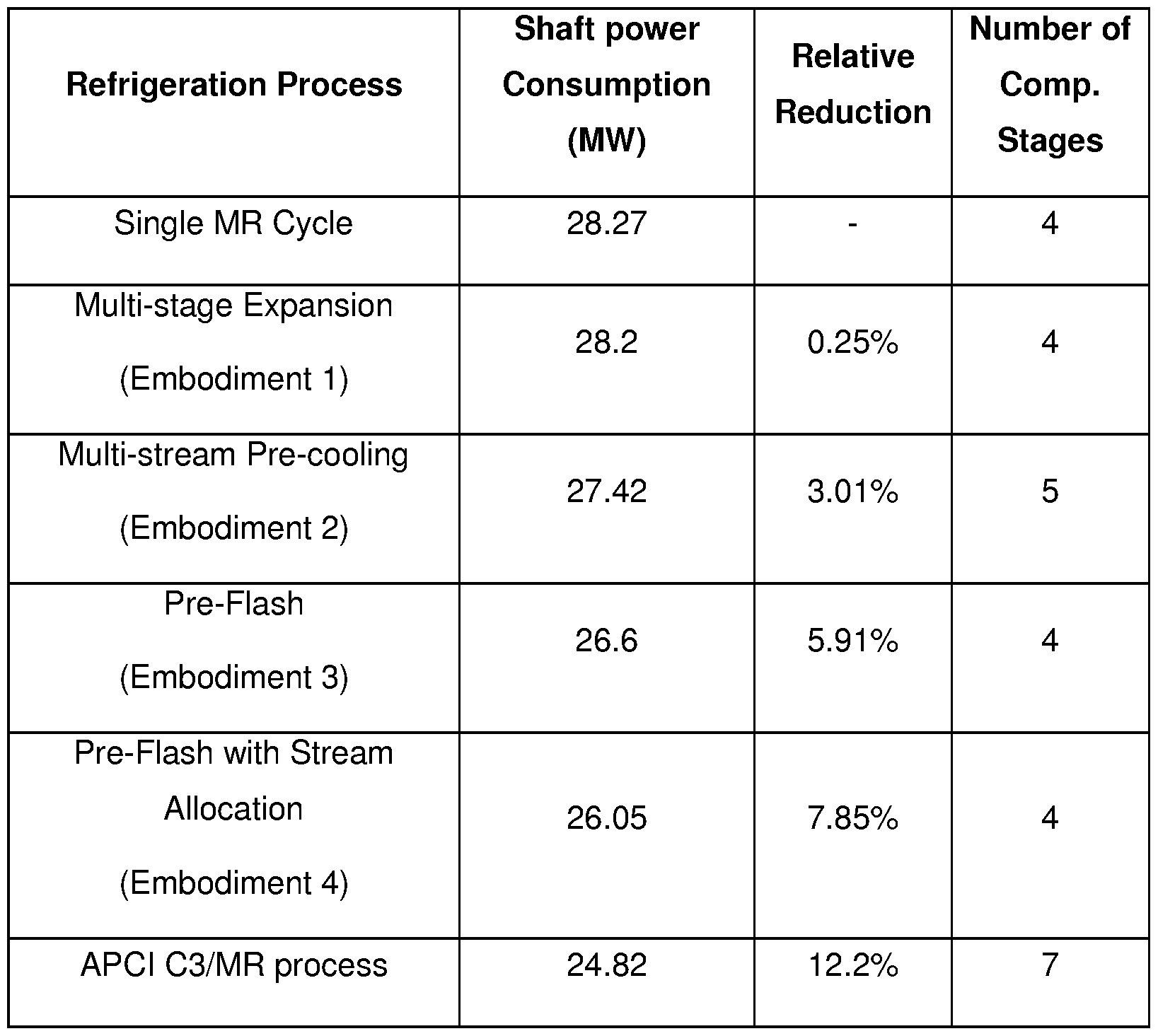
Claims
Priority Applications (11)
| Application Number | Priority Date | Filing Date | Title |
|---|---|---|---|
| JP2013500596A JP5868938B2 (en) | 2010-03-25 | 2011-03-25 | Cooling process |
| KR1020167010254A KR20160049040A (en) | 2010-03-25 | 2011-03-25 | Refrigeration process |
| EP11716988.8A EP2550496B1 (en) | 2010-03-25 | 2011-03-25 | Refrigeration process |
| US13/636,866 US9562717B2 (en) | 2010-03-25 | 2011-03-25 | Refrigeration process |
| GB1218823.1A GB2491796B (en) | 2010-03-25 | 2011-03-25 | Refrigeration process |
| CA2829666A CA2829666C (en) | 2010-03-25 | 2011-03-25 | Refrigeration process |
| CN2011800254958A CN103415752A (en) | 2010-03-25 | 2011-03-25 | Refrigeration process |
| KR1020127027954A KR20130079365A (en) | 2010-03-25 | 2011-03-25 | Refrigeration process |
| BR112012024317A BR112012024317A2 (en) | 2010-03-25 | 2011-03-25 | cooling processes to cool a natural gas product and liquefaction feed stream and refrigeration assembly |
| EA201290951A EA026653B1 (en) | 2010-03-25 | 2011-03-25 | Refrigeration process |
| AU2011231314A AU2011231314B2 (en) | 2010-03-25 | 2011-03-25 | Refrigeration process |
Applications Claiming Priority (4)
| Application Number | Priority Date | Filing Date | Title |
|---|---|---|---|
| GBGB1005016.9A GB201005016D0 (en) | 2010-03-25 | 2010-03-25 | Refrigeration process |
| GB1005016.9 | 2010-03-25 | ||
| GBPCT/GB2011/050444 | 2011-03-07 | ||
| GB2011050444 | 2011-03-07 |
Publications (2)
| Publication Number | Publication Date |
|---|---|
| WO2011117655A2 true WO2011117655A2 (en) | 2011-09-29 |
| WO2011117655A3 WO2011117655A3 (en) | 2014-03-13 |
Family
ID=44673702
Family Applications (1)
| Application Number | Title | Priority Date | Filing Date |
|---|---|---|---|
| PCT/GB2011/050617 WO2011117655A2 (en) | 2010-03-25 | 2011-03-25 | Refrigeration process |
Country Status (13)
| Country | Link |
|---|---|
| US (1) | US9562717B2 (en) |
| EP (1) | EP2550496B1 (en) |
| JP (1) | JP5868938B2 (en) |
| KR (1) | KR20160049040A (en) |
| CN (1) | CN103415752A (en) |
| AU (1) | AU2011231314B2 (en) |
| BR (1) | BR112012024317A2 (en) |
| CA (1) | CA2829666C (en) |
| CO (1) | CO6630156A2 (en) |
| EA (1) | EA026653B1 (en) |
| GB (1) | GB2491796B (en) |
| MY (1) | MY162011A (en) |
| WO (1) | WO2011117655A2 (en) |
Cited By (6)
| Publication number | Priority date | Publication date | Assignee | Title |
|---|---|---|---|---|
| CN103216998A (en) * | 2013-04-12 | 2013-07-24 | 北京安珂罗工程技术有限公司 | Method and system for compressing and conveying single-cycle mixed refrigerant |
| US9441877B2 (en) | 2010-03-17 | 2016-09-13 | Chart Inc. | Integrated pre-cooled mixed refrigerant system and method |
| US10480851B2 (en) | 2013-03-15 | 2019-11-19 | Chart Energy & Chemicals, Inc. | Mixed refrigerant system and method |
| US10663221B2 (en) | 2015-07-08 | 2020-05-26 | Chart Energy & Chemicals, Inc. | Mixed refrigerant system and method |
| US11408673B2 (en) | 2013-03-15 | 2022-08-09 | Chart Energy & Chemicals, Inc. | Mixed refrigerant system and method |
| US11428463B2 (en) | 2013-03-15 | 2022-08-30 | Chart Energy & Chemicals, Inc. | Mixed refrigerant system and method |
Families Citing this family (15)
| Publication number | Priority date | Publication date | Assignee | Title |
|---|---|---|---|---|
| US8011191B2 (en) | 2009-09-30 | 2011-09-06 | Thermo Fisher Scientific (Asheville) Llc | Refrigeration system having a variable speed compressor |
| US20160187056A1 (en) * | 2013-05-20 | 2016-06-30 | Korea Gas Corporation | Natural gas liquefaction process |
| US9903646B2 (en) * | 2014-10-07 | 2018-02-27 | L'air Liquide Societe Anonyme Pour L'etude Et L'exploitation Des Procedes Georges Claude | Apparatus for ethane liquefaction with demethanization |
| EP3230669A4 (en) * | 2014-12-12 | 2018-08-01 | Dresser Rand Company | System and method for liquefaction of natural gas |
| MY190843A (en) * | 2016-03-10 | 2022-05-12 | Jgc Corp | Method of determining mixed refrigerant composition for natural gas liquefying apparatus |
| FR3052240B1 (en) * | 2016-06-02 | 2020-02-21 | L'air Liquide, Societe Anonyme Pour L'etude Et L'exploitation Des Procedes Georges Claude | PROCESS FOR LIQUEFACTION OF CARBON DIOXIDE FROM A NATURAL GAS STREAM |
| FR3052239B1 (en) * | 2016-06-02 | 2020-02-21 | L'air Liquide, Societe Anonyme Pour L'etude Et L'exploitation Des Procedes Georges Claude | PROCESS FOR LIQUEFACTION OF NATURAL GAS AND CARBON DIOXIDE |
| US11112173B2 (en) * | 2016-07-01 | 2021-09-07 | Fluor Technologies Corporation | Configurations and methods for small scale LNG production |
| RU2640976C1 (en) * | 2017-05-05 | 2018-01-12 | Компания "Сахалин Энерджи Инвестмент Компани Лтд." | Method for controlling liquefaction of natural gas |
| JP6470482B1 (en) * | 2018-07-13 | 2019-02-13 | 千代田化工建設株式会社 | Method for determining mixed refrigerant composition of natural gas liquefier |
| KR102552636B1 (en) * | 2019-01-03 | 2023-07-07 | 한화오션 주식회사 | Refrigerant Circulation System And Method For Ship |
| AU2019445489A1 (en) * | 2019-05-13 | 2021-06-10 | Jgc Corporation | Operation guidance searching method and operation guidance searching system |
| JP7388230B2 (en) | 2020-02-17 | 2023-11-29 | 富士通株式会社 | Mixture performance optimization device, mixture performance optimization program, mixture performance optimization method, and mixed refrigerant |
| AU2020450354B2 (en) * | 2020-05-27 | 2024-03-07 | Chiyoda Corporation | Method and system for determining operating conditions of liquefied natural gas plant |
| US20220099364A1 (en) * | 2020-09-29 | 2022-03-31 | L'Air Liquide, Société Anonyme pour l'Etude et I'Exploitation des Procédés Georges Claude | Offshore liquefaction process without compression |
Family Cites Families (28)
| Publication number | Priority date | Publication date | Assignee | Title |
|---|---|---|---|---|
| DE1939114B2 (en) | 1969-08-01 | 1979-01-25 | Linde Ag, 6200 Wiesbaden | Liquefaction process for gases and gas mixtures, in particular for natural gas |
| CA928208A (en) | 1970-02-09 | 1973-06-12 | Bodnick Sheldon | Mixed refrigerant cycle |
| US3929438A (en) * | 1970-09-28 | 1975-12-30 | Phillips Petroleum Co | Refrigeration process |
| FR2280042A1 (en) | 1974-05-31 | 1976-02-20 | Teal Technip Liquefaction Gaz | Cooling of a gas mixt - by countercurrent contact with a recycled mixture, useful for cooling natural gas |
| DE2438443C2 (en) * | 1974-08-09 | 1984-01-26 | Linde Ag, 6200 Wiesbaden | Process for liquefying natural gas |
| FR2545589B1 (en) | 1983-05-06 | 1985-08-30 | Technip Cie | METHOD AND APPARATUS FOR COOLING AND LIQUEFACTING AT LEAST ONE GAS WITH LOW BOILING POINT, SUCH AS NATURAL GAS |
| US4901533A (en) | 1986-03-21 | 1990-02-20 | Linde Aktiengesellschaft | Process and apparatus for the liquefaction of a natural gas stream utilizing a single mixed refrigerant |
| US4846862A (en) * | 1988-09-06 | 1989-07-11 | Air Products And Chemicals, Inc. | Reliquefaction of boil-off from liquefied natural gas |
| US4843829A (en) * | 1988-11-03 | 1989-07-04 | Air Products And Chemicals, Inc. | Reliquefaction of boil-off from liquefied natural gas |
| JP3320934B2 (en) | 1994-12-09 | 2002-09-03 | 株式会社神戸製鋼所 | Gas liquefaction method |
| FR2743140B1 (en) * | 1995-12-28 | 1998-01-23 | Inst Francais Du Petrole | METHOD AND DEVICE FOR TWO-STEP LIQUEFACTION OF A GAS MIXTURE SUCH AS A NATURAL GAS |
| DE19612173C1 (en) | 1996-03-27 | 1997-05-28 | Linde Ag | Procedure for liquefaction of hydrocarbon rich process flow, especially natural gas |
| GB2326465B (en) | 1997-06-12 | 2001-07-11 | Costain Oil Gas & Process Ltd | Refrigeration cycle using a mixed refrigerant |
| FR2778232B1 (en) * | 1998-04-29 | 2000-06-02 | Inst Francais Du Petrole | METHOD AND DEVICE FOR LIQUEFACTION OF A NATURAL GAS WITHOUT SEPARATION OF PHASES ON THE REFRIGERANT MIXTURES |
| US6182469B1 (en) | 1998-12-01 | 2001-02-06 | Elcor Corporation | Hydrocarbon gas processing |
| US6347532B1 (en) * | 1999-10-12 | 2002-02-19 | Air Products And Chemicals, Inc. | Gas liquefaction process with partial condensation of mixed refrigerant at intermediate temperatures |
| TW480325B (en) * | 1999-12-01 | 2002-03-21 | Shell Int Research | Plant for liquefying natural gas |
| MY128820A (en) | 2000-04-25 | 2007-02-28 | Shell Int Research | Controlling the production of a liquefied natural gas product stream |
| US6427483B1 (en) | 2001-11-09 | 2002-08-06 | Praxair Technology, Inc. | Cryogenic industrial gas refrigeration system |
| DE10209799A1 (en) * | 2002-03-06 | 2003-09-25 | Linde Ag | Process for liquefying a hydrocarbon-rich stream |
| TWI314637B (en) * | 2003-01-31 | 2009-09-11 | Shell Int Research | Process of liquefying a gaseous, methane-rich feed to obtain liquefied natural gas |
| AU2004274706B2 (en) | 2003-09-23 | 2008-08-07 | Linde Aktiengesellschaft | Natural gas liquefaction process |
| US7082787B2 (en) * | 2004-03-09 | 2006-08-01 | Bp Corporation North America Inc. | Refrigeration system |
| DE102005010055A1 (en) * | 2005-03-04 | 2006-09-07 | Linde Ag | Process for liquefying a hydrocarbon-rich stream |
| US8600997B2 (en) | 2005-09-30 | 2013-12-03 | International Business Machines Corporation | Method and framework to support indexing and searching taxonomies in large scale full text indexes |
| US8181481B2 (en) | 2005-11-24 | 2012-05-22 | Shell Oil Company | Method and apparatus for cooling a stream, in particular a hydrocarbon stream such as natural gas |
| CN101008545A (en) | 2007-01-24 | 2007-08-01 | 河南中原绿能高科有限责任公司 | Novel second-order mixed refrigeration process used for natural gas liquefaction |
| CN101608860B (en) * | 2008-06-17 | 2011-08-17 | 北京安瑞科新能能源科技有限公司 | Gas liquefying process for mixed refrigerant and mixed refrigerant |
-
2011
- 2011-03-25 EA EA201290951A patent/EA026653B1/en not_active IP Right Cessation
- 2011-03-25 WO PCT/GB2011/050617 patent/WO2011117655A2/en active Application Filing
- 2011-03-25 AU AU2011231314A patent/AU2011231314B2/en not_active Ceased
- 2011-03-25 US US13/636,866 patent/US9562717B2/en not_active Expired - Fee Related
- 2011-03-25 GB GB1218823.1A patent/GB2491796B/en not_active Expired - Fee Related
- 2011-03-25 KR KR1020167010254A patent/KR20160049040A/en not_active Application Discontinuation
- 2011-03-25 CA CA2829666A patent/CA2829666C/en not_active Expired - Fee Related
- 2011-03-25 JP JP2013500596A patent/JP5868938B2/en not_active Expired - Fee Related
- 2011-03-25 EP EP11716988.8A patent/EP2550496B1/en not_active Not-in-force
- 2011-03-25 CN CN2011800254958A patent/CN103415752A/en active Pending
- 2011-03-25 BR BR112012024317A patent/BR112012024317A2/en not_active Application Discontinuation
- 2011-03-25 MY MYPI2012004227A patent/MY162011A/en unknown
-
2012
- 2012-10-25 CO CO12191215A patent/CO6630156A2/en unknown
Non-Patent Citations (2)
| Title |
|---|
| LEE, G.C.: "PhD thesis", 2001, UMIST, article "Optimal design and analysis of refrigeration systems for low temperature processes" |
| VAIDYARAMAN, S., MARANAS, C.D.: "Synthesis of mixed refrigerant cascade cycles", CHEMICAL ENGINEERING COMMUNICATIONS, vol. 189, no. 8, 2002, pages 1057 - 1078 |
Cited By (8)
| Publication number | Priority date | Publication date | Assignee | Title |
|---|---|---|---|---|
| US9441877B2 (en) | 2010-03-17 | 2016-09-13 | Chart Inc. | Integrated pre-cooled mixed refrigerant system and method |
| US10502483B2 (en) | 2010-03-17 | 2019-12-10 | Chart Energy & Chemicals, Inc. | Integrated pre-cooled mixed refrigerant system and method |
| US10480851B2 (en) | 2013-03-15 | 2019-11-19 | Chart Energy & Chemicals, Inc. | Mixed refrigerant system and method |
| US11408673B2 (en) | 2013-03-15 | 2022-08-09 | Chart Energy & Chemicals, Inc. | Mixed refrigerant system and method |
| US11428463B2 (en) | 2013-03-15 | 2022-08-30 | Chart Energy & Chemicals, Inc. | Mixed refrigerant system and method |
| CN103216998A (en) * | 2013-04-12 | 2013-07-24 | 北京安珂罗工程技术有限公司 | Method and system for compressing and conveying single-cycle mixed refrigerant |
| US10663221B2 (en) | 2015-07-08 | 2020-05-26 | Chart Energy & Chemicals, Inc. | Mixed refrigerant system and method |
| US11408676B2 (en) | 2015-07-08 | 2022-08-09 | Chart Energy & Chemicals, Inc. | Mixed refrigerant system and method |
Also Published As
| Publication number | Publication date |
|---|---|
| CA2829666A1 (en) | 2011-09-29 |
| GB201218823D0 (en) | 2012-12-05 |
| GB2491796B (en) | 2016-02-24 |
| JP2013540973A (en) | 2013-11-07 |
| WO2011117655A3 (en) | 2014-03-13 |
| US9562717B2 (en) | 2017-02-07 |
| MY162011A (en) | 2017-05-31 |
| US20130008204A1 (en) | 2013-01-10 |
| EP2550496A2 (en) | 2013-01-30 |
| CN103415752A (en) | 2013-11-27 |
| JP5868938B2 (en) | 2016-02-24 |
| EA201290951A1 (en) | 2013-07-30 |
| BR112012024317A2 (en) | 2016-05-24 |
| GB2491796A (en) | 2012-12-12 |
| AU2011231314A1 (en) | 2012-11-15 |
| EP2550496B1 (en) | 2017-06-14 |
| AU2011231314B2 (en) | 2016-02-04 |
| KR20160049040A (en) | 2016-05-04 |
| CO6630156A2 (en) | 2013-03-01 |
| CA2829666C (en) | 2018-04-17 |
| EA026653B1 (en) | 2017-05-31 |
Similar Documents
| Publication | Publication Date | Title |
|---|---|---|
| CA2829666C (en) | Refrigeration process | |
| He et al. | Review on the design and optimization of natural gas liquefaction processes for onshore and offshore applications | |
| CA3005327C (en) | Pre-cooling of natural gas by high pressure compression and expansion | |
| Finn et al. | Developments in natural gas liquefaction | |
| RU2270408C2 (en) | Method and device for liquefied gas cooling | |
| RU2447382C2 (en) | Method and device for liquefaction of hydrocarbon-containing raw materials flow | |
| Qyyum et al. | Innovative propane-nitrogen two-phase expander refrigeration cycle for energy-efficient and low-global warming potential LNG production | |
| US20180231303A1 (en) | Pre-Cooling of Natural Gas by High Pressure Compression and Expansion | |
| US11815308B2 (en) | Pretreatment and pre-cooling of natural gas by high pressure compression and expansion | |
| Kamalinejad et al. | Thermodynamic design of a cascade refrigeration system of liquefied natural gas by applying mixed integer non-linear programming | |
| RU2743094C2 (en) | Improved method and system for cooling a hydrocarbon flow using a gas-phase coolant | |
| Pwaga | Sensitivity analysis of proposed LNG liquefaction processes for LNG FPSO | |
| Rehman et al. | Investigation of improvement potential of Modified Single Mixed Refrigerant (MSMR) LNG process in terms of avoidable and unavoidable exergy destruction | |
| Zhu et al. | Selection and simulation of offshore LNG liquefaction process | |
| US11806639B2 (en) | Pretreatment and pre-cooling of natural gas by high pressure compression and expansion | |
| Akinsipe et al. | A study of LNG processes to determine the effect of end flash systems on efficiency | |
| KR102108924B1 (en) | Natural gas liquefaction treatment device | |
| US10571187B2 (en) | Temperature controlled method to liquefy gas and a production plant using the method | |
| Baek et al. | DEVELOPMENT OF THE HYBRID JT‐EXPANDER CYCLE FOR NG LIQUEFACTION CYCLE | |
| KR20130079365A (en) | Refrigeration process | |
| Kim et al. | Advanced Liquefaction Cycle for Natural Gas | |
| Henryawan et al. | Optimization of Small-Scale Natural Gas Liquefaction using Nitrogen Expander with Precooled Cycle | |
| Soujoudi | Thermoeconomic and Environmental Advantages of Ammonia Precooled Mixed Refrigerant in Liquefied Natural Gas Cycle |
Legal Events
| Date | Code | Title | Description |
|---|---|---|---|
| 121 | Ep: the epo has been informed by wipo that ep was designated in this application |
Ref document number: 11716988 Country of ref document: EP Kind code of ref document: A2 |
|
| WWE | Wipo information: entry into national phase |
Ref document number: 13636866 Country of ref document: US |
|
| WWE | Wipo information: entry into national phase |
Ref document number: 2013500596 Country of ref document: JP |
|
| ENP | Entry into the national phase |
Ref document number: 1218823 Country of ref document: GB Kind code of ref document: A Free format text: PCT FILING DATE = 20110325 |
|
| REEP | Request for entry into the european phase |
Ref document number: 2011716988 Country of ref document: EP |
|
| WWE | Wipo information: entry into national phase |
Ref document number: 1218823.1 Country of ref document: GB Ref document number: 2011716988 Country of ref document: EP |
|
| WWE | Wipo information: entry into national phase |
Ref document number: 201290951 Country of ref document: EA |
|
| ENP | Entry into the national phase |
Ref document number: 20127027954 Country of ref document: KR Kind code of ref document: A |
|
| WWE | Wipo information: entry into national phase |
Ref document number: 12191215 Country of ref document: CO |
|
| ENP | Entry into the national phase |
Ref document number: 2011231314 Country of ref document: AU Date of ref document: 20110325 Kind code of ref document: A |
|
| REG | Reference to national code |
Ref country code: BR Ref legal event code: B01A Ref document number: 112012024317 Country of ref document: BR |
|
| ENP | Entry into the national phase |
Ref document number: 2829666 Country of ref document: CA |
|
| ENP | Entry into the national phase |
Ref document number: 112012024317 Country of ref document: BR Kind code of ref document: A2 Effective date: 20120925 |