WO2011105454A1 - 無線基地局装置及びスケジューリング方法 - Google Patents
無線基地局装置及びスケジューリング方法 Download PDFInfo
- Publication number
- WO2011105454A1 WO2011105454A1 PCT/JP2011/054038 JP2011054038W WO2011105454A1 WO 2011105454 A1 WO2011105454 A1 WO 2011105454A1 JP 2011054038 W JP2011054038 W JP 2011054038W WO 2011105454 A1 WO2011105454 A1 WO 2011105454A1
- Authority
- WO
- WIPO (PCT)
- Prior art keywords
- relay
- station apparatus
- radio
- base station
- mobile terminal
- Prior art date
- Legal status (The legal status is an assumption and is not a legal conclusion. Google has not performed a legal analysis and makes no representation as to the accuracy of the status listed.)
- Ceased
Links
Images


Classifications
-
- H—ELECTRICITY
- H04—ELECTRIC COMMUNICATION TECHNIQUE
- H04W—WIRELESS COMMUNICATION NETWORKS
- H04W72/00—Local resource management
- H04W72/50—Allocation or scheduling criteria for wireless resources
- H04W72/54—Allocation or scheduling criteria for wireless resources based on quality criteria
- H04W72/542—Allocation or scheduling criteria for wireless resources based on quality criteria using measured or perceived quality
-
- H—ELECTRICITY
- H04—ELECTRIC COMMUNICATION TECHNIQUE
- H04W—WIRELESS COMMUNICATION NETWORKS
- H04W84/00—Network topologies
- H04W84/02—Hierarchically pre-organised networks, e.g. paging networks, cellular networks, WLAN [Wireless Local Area Network] or WLL [Wireless Local Loop]
- H04W84/04—Large scale networks; Deep hierarchical networks
- H04W84/042—Public Land Mobile systems, e.g. cellular systems
- H04W84/047—Public Land Mobile systems, e.g. cellular systems using dedicated repeater stations
Definitions
- the present invention relates to a radio base station apparatus that performs adaptive AF (Amplify-and-Forward) type relay transmission and a scheduling method.
- adaptive AF Anamplify-and-Forward
- IMT-Advanced International Mobile Telecommunications-Advanced
- ITU-R International Telecommunication Union-Radio Communication Sector
- relay transmission has attracted attention as a technology for realizing high-speed wireless transmission with wide coverage in a power limited environment.
- the relay transmission is an AF (Amplify-and-Forward) type that amplifies and transfers a received RF (Radio Frequency) signal without demodulating, and a received signal to be relayed once in a radio relay station device. It can be roughly classified into DF (Decode-and-Forward) type in which the decision data is re-encoded, re-modulated and transferred.
- AF Analog-and-Forward
- DF Decode-and-Forward
- the AF relay transmission has an advantage that the transmission delay time required for the relay transfer is small.
- the noise and the interference component included in the received signal are amplified and transferred together with the desired signal component. Then, there is a problem that inter-cell interference increases.
- frequency utilization efficiency deteriorates because it is necessary to allocate a part of a communication band to a relay signal.
- Non-patent Document 1 Non-patent Document 1
- relay transmission to a mobile terminal device in the vicinity of a radio base station device is turned OFF, and also when relay transmission is performed, only a radio relay station device with a short distance from the mobile terminal device is turned ON. By doing so, the problem of unnecessary frequency utilization efficiency degradation due to relay transmission and other cell interference amplification is reduced. Also in this adaptive AF type relay transmission method, the user throughput characteristics that can be realized greatly depend on the amount of interference between cells.
- the present invention has been made in view of such a point, and an object thereof is to provide a radio base station apparatus and a scheduling method capable of improving user throughput characteristics in an adaptive AF relay transmission method.
- the radio base station apparatus of the present invention includes a receiving unit that receives a signal including a reference signal, and a path loss and fading between the mobile terminal apparatus, the radio relay apparatus, and the radio base station apparatus for uplink using the reference signal.
- Channel state measuring means for measuring the instantaneous channel gain according to, and scheduling means for allocating downlink resources based on the instantaneous channel gain due to the path loss and fading.
- the scheduling method of the present invention includes a step of receiving a signal including a reference signal, and an uplink path loss and fading between the mobile terminal apparatus, the radio relay apparatus, and the radio base station apparatus for the uplink using the reference signal. And a step of allocating downlink resources based on the instantaneous channel gain due to the path loss and fading.
- the user throughput characteristic can be improved in the adaptive AF relay transmission method.
- the adaptive AF relay transmission method which is the premise of the scheduling of the present invention will be described.
- the adaptive AF relay transmission in the cellular environment previously proposed by the present inventor reduces the problem of allocation time and frequency utilization efficiency loss associated with the amplification of other cell interference and the relay transmission in the conventional AF relay transmission (repeater). .
- each radio relay station apparatus i 1, 2,..., N RS : N RS is the number of radio relay station apparatuses in the cell) is unique.
- a downlink reference signal (downlink BS / RS specific reference signal: pilot channel signal) is transmitted.
- the mobile terminal apparatus UE k measures the amount of path loss (distance attenuation + shadowing) PL BS, k and PL RS, i, k between the radio base station apparatus and each radio relay station apparatus using the reference signal.
- the mobile terminal apparatus UE k periodically reports PL BS, k and PL RS, i, k to the radio base station apparatus.
- the radio base station apparatus adaptively selects the radio relay station apparatus used for transmission of the mobile terminal apparatus UE k using PL BS, k and PL RS, i, k in two steps.
- the threshold value T 20 dB can be set.
- all the time / frequency resources allocated to the mobile terminal apparatus UE k are used for transmission of the mobile terminal apparatus.
- 1/2 of the allocated time is used for transmission of the radio relay station apparatus.
- a radio relay station apparatus used for relay transmission is further selected in the second step.
- the radio base station apparatus selects a radio relay station apparatus to be used during uplink transmission of the mobile terminal apparatus UE k based on PL RS, i, k . Specifically, only a radio relay station apparatus i that satisfies the following equation (2) is used using a predetermined threshold value ⁇ .
- the first step by canceling relay transmission of the mobile terminal device in the vicinity of the cell, time / frequency resources are improved and the amplification amount of other cell interference is reduced.
- the second step by setting the amplification factor of the radio relay station apparatus, which has a small contribution to the increase in received power of the desired mobile terminal apparatus, to 0, the amplification amount of other cell interference is further reduced.
- the radio base station apparatus notifies the number of the radio relay station apparatus used for the mobile terminal apparatus UE k to all radio relay station apparatuses in advance via the downlink control channel. Thereafter, the radio base station apparatus periodically determines assignment of uplink transmission to each mobile terminal apparatus based on the scheduler, and notifies each mobile terminal apparatus with a downlink control signal. This scheduling information is also received by each radio relay station device in the cell.
- all the radio relay station apparatuses set the power amplification factor to zero. Also, when the mobile terminal apparatus performs relay transmission, only the radio relay station apparatus selected in advance for the mobile terminal apparatus sets the power amplification factor to be greater than 0, and the other radio relay station apparatuses use the power amplification factor. Set to 0.
- the path loss between the mobile terminal apparatus and the radio base station apparatus is PL UE-BS
- the path loss between the mobile terminal apparatus and the radio relay station apparatus is PL UE-RS
- the radio relay station apparatus and the radio base station apparatus The path loss between them is PL RS-BS (both are dB values).
- the instantaneous channel gain of the frequency block (i) due to fading between the mobile terminal apparatus and the radio base station apparatus is F UE-BS (i)
- the instantaneous channel gain of the frequency block (i) due to the mobile terminal apparatus-fading is F UE-RS (i)
- the instantaneous channel gain of the frequency block (i) due to fading between the radio relay station apparatus and the radio base station apparatus is F RS-BS (i) .
- G be the power amplification gain of the radio relay station apparatus.
- Time division multiplexing is used for multiplexing the transmission signal of the mobile terminal apparatus and the relay signal of the radio relay station apparatus.
- the mobile terminal apparatus transmits one radio packet in the first time slot, It is assumed that the transmission signal of the mobile terminal apparatus received by the radio relay station apparatus in the first time slot in the time slot is transferred to the radio base station apparatus.
- the mobile terminal device transmits two radio packets using two time slots.
- the instantaneous channel gain due to the path loss and fading between the mobile terminal apparatus, radio relay apparatus and radio base station apparatus for the uplink is measured, and based on the instantaneous channel gain due to the path loss and fading. Assign downlink resources.
- Three methods can be considered as the scheduling method of the present invention.
- the radio relay station apparatus is installed in a state where the communication environment is favorable with the radio base station apparatus. For this reason, it is considered that the bottleneck of the channel state is not the link between the radio relay station apparatus and the radio base station apparatus, but the link between the radio relay station apparatus and the mobile terminal apparatus. Therefore, in the first method, the channel state of the link between the radio relay station device and the mobile terminal device is measured, and downlink resource allocation is performed from a link with a good channel state (a link with a large metric). In the first method, the first time slot for transmission between the mobile terminal apparatus and the radio relay station apparatus and the transmission for transmission between the radio relay station apparatus and the radio base station apparatus within two time slots. It is assumed that the fading fluctuation within the second time slot of the second time slot is constant.
- the metric of the frequency block i at the time of relay transmission is determined based on the instantaneous to average received signal power ratio in the radio base station apparatus when the same frequency block is used in two time slots. That is, in the second method, downlink resource allocation is performed based on the value of the following formula (1).
- the channel state of the link between the mobile terminal device, the radio relay station device, and the mobile terminal device is measured, the metric is calculated by the above equation (1), and the link resource from the link with the large metric to the downlink resource Make an assignment. Even in this case, within the two time slots of the first time slot for transmission between the mobile terminal apparatus and the radio relay station apparatus and the second time slot for transmission between the radio relay station apparatus and the radio base station apparatus.
- the fading fluctuation of is assumed to be constant.
- the amount of calculation can be reduced.
- (Third method) scheduling is performed independently in the first time slot and the second time slot. That is, in the third method, downlink resource allocation is performed based on instantaneous channel gain due to fading between the mobile terminal apparatus and the radio relay apparatus in the first time slot, and the radio relay apparatus is configured in the second time slot. Downlink resource allocation is performed based on instantaneous channel gain due to fading with the radio base station apparatus.
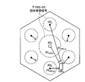
- FIG. 2 is a conceptual diagram of the relay transmission system.
- a radio relay station apparatus exists in a cell in addition to a radio base station apparatus (BS: eNB) and a mobile terminal apparatus (UE).
- BS radio base station apparatus
- UE mobile terminal apparatus
- FIG. 2 since the mobile terminal apparatus UE A is located at the cell edge, when transmitting an uplink signal directly to the radio base station apparatus BS A of the serving cell, the mobile terminal apparatus in the vicinity of the radio base station apparatus BS A It is conceivable to transmit with stronger power than However, since the radio relay station apparatus RS A exist between the mobile terminal UE A and the radio base station apparatus BS A, the uplink signal from the mobile terminal apparatus UE A, via the radio relay station apparatus RS A Transmit to the radio base station apparatus BS A.
- BS radio base station apparatus
- the radio relay station apparatus RS A may be a mobile terminal apparatus or a fixed station in terms of operation principle. Also, unlike the radio base station apparatus, the radio relay station apparatus only needs to have a function of relaying signals, and therefore can be installed more simply and cheaper than the radio base station apparatus. For relay transmission systems, see, for example, A. Nostatinia, TE Hunter, and A. Hedayat, "Cooperative Communication in Wireless Networks," IEEE Communications Magazine, Vol. 42, No. 10, pp. 74-80, Oct. 2004. Are listed. All this content is included here.
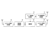
- FIG. 3 is a diagram showing a configuration of the radio relay station apparatus according to the embodiment of the present invention.
- the radio relay station apparatus shown in FIG. 3 includes a downlink control signal receiving unit 11 that receives a downlink control signal from a radio base station apparatus, a relay gain control unit 12 that controls a relay gain for a signal to be relayed, and a mobile terminal
- An uplink signal receiving unit 13 that receives an uplink signal from a device, a frequency converting unit 14 that converts the frequency of the received signal into a frequency of the transmitted signal, and a relay gain when the transmission frequency and the receiving frequency are different Therefore, it mainly includes an amplification unit 15 that amplifies an uplink signal to be relayed and an uplink signal transmission unit 16 that transmits the uplink signal to the radio base station apparatus.
- the downlink control signal receiving unit 11 receives a downlink control signal from the radio base station apparatus.
- This downlink control signal includes relay information indicating whether the mobile terminal apparatus performs relay transmission. Further, the downlink control signal includes uplink schedule information (resource allocation information).
- the downlink control signal receiving unit 11 demodulates the downlink control signal and acquires uplink scheduling information and relay information.
- the relay gain control unit 12 controls the relay gain when relaying an uplink signal based on information obtained from the downlink control signal. That is, the relay gain control unit 12 controls the relay gain at the time of relay transmission when the relay information is information to be relayed.
- the relay amplification factor control unit 12 outputs information on the relay amplification factor to the amplification unit 15.
- the amplification unit 15 amplifies the uplink signal (uplink signal to be relayed) frequency-converted by the frequency conversion unit 14 with the relay amplification factor received from the relay amplification factor control unit 12.
- the uplink signal receiving unit 13 receives an uplink signal from the mobile terminal device.
- the uplink signal reception unit 13 outputs the uplink signal to the frequency conversion unit 14.
- the frequency conversion unit 14 converts the frequency of the reception signal into the frequency of the transmission signal.
- the frequency conversion unit 14 outputs the uplink signal after the frequency conversion to the amplification unit 15.
- the reception frequency and the transmission frequency of the radio relay station apparatus are different when relaying is performed.
- the same frequency is used for the reception frequency and the transmission frequency of the radio relay station apparatus, and the time slot and / or the code is changed instead, the frequency conversion unit 14 is unnecessary.
- the uplink signal transmission unit 16 transmits the uplink signal amplified by the amplification unit 15 with the relay amplification factor to the radio base station apparatus. That is, the uplink signal transmission unit 16 transmits the uplink signal amplified with the controlled relay amplification factor to the radio base station apparatus.
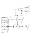
- FIG. 4 is a diagram showing a configuration of the radio base station apparatus according to the embodiment of the present invention.
- the radio base station apparatus shown in FIG. 4 allocates radio resources, an uplink channel state measurement unit 21 that measures uplink channel states, an uplink control signal reception unit 22 that receives uplink control signals from mobile terminal devices, and Including a scheduling unit 23 that performs, a user control signal generation unit 24 that generates a control signal for a user, a relay station control signal generation unit 25 that generates a control signal related to relay information for a radio relay station device, and a control signal and user data
- a baseband signal generation unit 26 that generates a baseband signal
- an RF signal generation unit 27 that converts the baseband signal into a radio frequency signal and generates an RF signal
- the relay information generating unit 28 mainly generates the relay information to be generated.
- the uplink channel state measurement unit 21 measures the uplink channel state using the reference signal transmitted from the mobile terminal apparatus.
- a sounding reference signal SRS
- the channel state is an instantaneous channel gain of the frequency block (i) due to fading among the mobile terminal device, the radio relay station device, and the radio base station device.
- the uplink channel state measurement unit 21 outputs uplink channel state information to the scheduling unit 23.
- the uplink control signal receiving unit 22 receives an uplink control signal from each mobile terminal apparatus.
- the control signal includes, for example, a path loss, a scheduling request (SR), an amount indicating downlink reception quality (CQI: Channel Quality Indicator), and the like.
- the uplink control signal receiving unit 22 outputs the uplink control signal to the scheduling unit 23.
- the relay information generation unit 28 generates relay information for each user based on reception quality such as downlink CQI and / or uplink reception SINR or not to determine whether or not the mobile terminal apparatus performs relay transmission. That is, the relay information generation unit 28 determines relay information for each user as to whether or not the mobile terminal apparatus performs relay transmission.
- the relay information is notified to the scheduling unit 23, the user control signal generation unit 24, and the relay station control signal generation unit 25. Note that when the uplink signal is not relayed, the relay information may not be notified to the scheduling unit 23.
- the relay station control signal generation unit 25 generates a control signal related to relay information for the radio relay station device. Further, the relay station control signal generation unit 25 controls the relay amplification factor when relaying the uplink signal. That is, the relay station control signal generation unit 25 controls the relay amplification factor at the time of relay transmission when relay transmission is performed.
- the relay station control signal generator 25 determines the relay amplification factor for relay transmission when performing relay transmission.
- the relay station control signal generation unit 25 generates information on the relay amplification factor thus obtained as a relay station control signal, and outputs it to the baseband signal generation unit 26.
- the scheduling unit 23 performs scheduling and allocates uplink and downlink radio resources.
- the scheduling method the above three methods can be cited. That is, (1) a method for allocating downlink resources based on instantaneous channel gain due to fading between the mobile terminal device and the radio relay device, and (2) downlink resources based on the value of equation (1) above (3)
- downlink resource allocation is performed based on the instantaneous channel gain due to fading between the mobile terminal apparatus and the radio relay apparatus, and in the second time slot, the radio relay apparatus and the radio
- downlink resource allocation is performed based on instantaneous channel gain due to fading with a base station apparatus.
- the scheduling unit 23 uses the instantaneous channel gain of the frequency block (i) due to fading measured by the uplink channel state measurement unit 21 and the path loss notified from the mobile terminal device when performing the scheduling.
- the scheduling unit 23 outputs uplink scheduling information and / or downlink scheduling information to the user control signal generation unit 24.
- the user control signal generator 24 generates control information to be notified to each mobile terminal device.
- This control information includes at least uplink scheduling information / downlink scheduling information, and also includes relay information as necessary.
- the user control signal generation unit 24 outputs the control signal to the baseband signal generation unit 26.
- the baseband signal generation unit 26 generates a baseband signal including various control information and user data included in the downlink signal.
- the baseband signal generation unit 26 outputs the generated baseband signal to the RF signal generation unit 27.
- the RF signal generation unit 27 converts the baseband signal into a transmission signal (RF signal) for wireless transmission. In this way, the radio base station apparatus transmits relay information including information on the relay amplification factor to the radio relay station apparatus.
- RS-TPC method 1 In the first radio relay station apparatus power gain control method (RS-TPC method 1), the received signal power density in the radio base station apparatus via the radio relay station apparatus of the mobile terminal apparatus that performed relay transmission is as if The power amplification factor of the radio relay station apparatus is controlled to be almost the same as when the mobile terminal apparatus exists at the position of the radio relay station apparatus and transmission is performed without relay transmission.
- Equation (3) the signal power density of the mobile terminal apparatus received by the radio base station apparatus via the radio relay station apparatus is as shown in Equation (3).
- R (relay) R 1 (no relay) .
- G T (no relay) -T (relay) + (1- ⁇ (relay) ) PL UE-RS + ⁇ (no relay) PL RS-BS
- RS-TPC method 2 In the second radio relay station apparatus power gain control method (RS-TPC method 2), the received signal power density in the radio base station apparatus via the radio relay station apparatus of the mobile terminal apparatus that performed relay transmission is as if The power amplification factor of the radio relay station apparatus is controlled so as to be almost the same as the case of transmission without relay transmission.
- R R 2 (no relay) .
- G T (no relay) -T (relay) + (1- ⁇ (relay) ) PL UE-RS -(1- ⁇ (no relay) ) PL UE-BS + PL RS-BS
- the power amplification factor control of these radio relay station apparatuses may be performed by the radio relay station apparatus or the radio base station apparatus.
- parameters in Expression (5) or Expression (7) are acquired from the radio base station apparatus or mobile terminal apparatus as necessary.
- the path loss PL UE-BS of the RS-TPC method 2 is acquired by signaling from a radio base station apparatus or acquired by notification from a mobile terminal apparatus.
- the mobile terminal apparatus measures the path loss PL UE-BS and notifies the radio base station apparatus directly or via the radio relay station apparatus.
- the parameter including the path loss PL UE-BS is notified to the relay station apparatus.
- the mobile terminal apparatus measures the path loss PL UE-BS and notifies the radio relay station apparatus.
- the radio relay station apparatus controls the power amplification factor of the radio relay station apparatus together with information on other parameters notified from the radio base station apparatus. This series of notification and control is generally performed periodically in a long cycle or triggered by an instruction by a control signal from a radio base station apparatus or a radio relay station apparatus.
- ⁇ no relay
- the RS-TPC method 1 and the RS-TPC method 2 are equivalent.
- uplink OFDMA Orthogonal frequency division multiple access
- 8 UEs mobile terminal devices
- the number of allocated frequency blocks per UE is limited to 3.
- Fig. 5 shows the cumulative distribution of user throughput. Also shown is the case where frequency blocks are assigned fixedly by round robin (comparative example).
- the proportional fair type scheduling method at the time of adaptive AF type relay transmission when the three scheduling methods are compared, the throughput increases in the order of the first method, the second method, and the third method.
- the second method is simpler than the third method, but the obtained throughput is almost the same as the third method. Therefore, refer to the sounding of terminal transmission like LTE (Long Term Evolution). It is considered suitable for a system that calculates a metric based on a signal.
- LTE Long Term Evolution
- the channel state is obtained using the instantaneous channel gain of the frequency block (i) due to path loss and fading, and radio resources are allocated according to the channel state. Can be improved.
- the present invention is not limited to the above embodiment, and can be implemented with various modifications.
- the present invention is not limited to this, and the path loss may be obtained by other methods.
- the number of processing units and processing procedures in the above description can be appropriately changed and implemented.
- Each element shown in the figure represents a function, and each functional block may be realized by hardware or software. Other modifications can be made without departing from the scope of the present invention.
- the present invention is useful for an LTE system and an LTE-Advanced radio base station apparatus and a scheduling method that are developed systems thereof.
Landscapes
- Engineering & Computer Science (AREA)
- Quality & Reliability (AREA)
- Computer Networks & Wireless Communication (AREA)
- Signal Processing (AREA)
- Mobile Radio Communication Systems (AREA)
Abstract
Description
本発明のスケジューリングの前提となる適応AF型リレー伝送法について説明する。本発明者が先に提案したセルラ環境における適応AF型リレー伝送は、従来のAF型リレー伝送(リピータ)における他セル干渉の増幅とリレー伝送に伴う割り当て時間・周波数利用効率損の問題を軽減する。

第1の方法においては、リレー伝送時の周波数ブロックiのメトリックを移動端末装置-無線中継局装置間のリンクの瞬時チャネル利得で定める(Mrelay=FUE-RS(i))。すなわち、第1の方法では、移動端末装置と無線中継装置との間のフェージングによる瞬時チャネル利得に基づいて下りリンクのリソース割り当てを行う。
第2の方法においては、リレー伝送時の周波数ブロックiのメトリックを2時間スロットで同一の周波数ブロックを用いた場合の無線基地局装置での瞬時対平均受信信号電力比に基づいて定める。すなわち、第2の方法では、下記式(1)の値に基づいて下りリンクのリソース割り当てを行う。

第3の方法においては、第1時間スロット、第2時間スロットで独立にスケジューリングを行う。すなわち、第3の方法においては、第1時間スロットで移動端末装置と無線中継装置との間のフェージングによる瞬時チャネル利得に基づいて下りリンクのリソース割り当てを行い、第2時間スロットで無線中継装置と無線基地局装置との間のフェージングによる瞬時チャネル利得に基づいて下りリンクのリソース割り当てを行う。このとき、第1時間スロットの周波数ブロックiのメトリックはFUE-RS(i)に基づき(Mrelay=FUE-RS(i))、第2時間スロットの周波数ブロックiのメトリックはFRS-BS(i)に基づく(Mrelay=FRS-BS(i))。第3の方法によれば、より効率のよい無線リソースの割り当てが可能となる。
(1)RS-TPC方法1
1つ目の無線中継局装置電力増幅率制御法(RS-TPC方法1)においては、リレー伝送を行った移動端末装置の無線中継局装置経由の無線基地局装置における受信信号電力密度が、あたかも無線中継局装置の位置に移動端末装置が存在してリレー伝送なしで伝送した場合とほぼ同じになるように無線中継局装置の電力増幅率を制御する。
式(3)
R(relay)=G+P(relay)-PLUE-RS-PLRS-BS
=G+T(relay)+Pnoise-(1-α(relay))PLUE-RS-PLRS-BS
式(4)
R1 (no relay)=T(no relay)+Pnoise-(1-α(no relay))PLRS-BS
式(5)
G=T(no relay)-T(relay)+(1-α(relay))PLUE-RS+α(no relay)PLRS-BS
2つ目の無線中継局装置電力増幅率制御法(RS-TPC方法2)においては、リレー伝送を行った移動端末装置の無線中継局装置経由の無線基地局装置における受信信号電力密度が、あたかもリレー伝送なしで伝送した場合とほぼ同じになるように無線中継局装置の電力増幅率を制御する。
式(6)
R2 (no relay)=T(no relay)+Pnoise-(1-α(no relay))PLUE-BS
式(7)
G=T(no relay)-T(relay)+(1-α(relay))PLUE-RS
-(1-α(no relay))PLUE-BS+PLRS-BS
4.32MHz帯域幅を24周波数ブロックに分割した上りリンクOFDMA(Orthogonal frequency division multiple access)を仮定し、1セル当たり8UE(移動端末装置)をランダムな位置に配置した。スケジューリングにおいては1UE当たりの割り当て周波数ブロック数を3に制限した。
Claims (8)
- 参照信号を含む信号を受信する受信手段と、前記参照信号を用いて、上りリンクについての移動端末装置、無線中継装置及び無線基地局装置の間のパスロス及びフェージングによる瞬時チャネル利得を測定するチャネル状態測定手段と、前記パスロス及びフェージングによる瞬時チャネル利得に基づいて下りリンクのリソース割り当てを行うスケジューリング手段と、を具備することを特徴とする無線基地局装置。
- 前記スケジューリング手段は、前記移動端末装置と前記無線中継装置との間のフェージングによる瞬時チャネル利得に基づいて下りリンクのリソース割り当てを行うことを特徴とする請求項1記載の無線基地局装置。
- 前記スケジューリング手段は、第1時間スロットで前記移動端末装置と前記無線中継装置との間のフェージングによる瞬時チャネル利得に基づいて下りリンクのリソース割り当てを行い、第2時間スロットで前記無線中継装置と前記無線基地局装置との間のフェージングによる瞬時チャネル利得に基づいて下りリンクのリソース割り当てを行うことを特徴とする請求項1記載の無線基地局装置。
- 前記スケジュール手段は、下記式(1)の値に基づいて下りリンクのリソース割り当てを行うことを特徴とする請求項1記載の無線基地局装置。

- 参照信号を含む信号を受信する工程と、前記参照信号を用いて、上りリンクについての移動端末装置、無線中継装置及び無線基地局装置の間のパスロス及びフェージングによる瞬時チャネル利得を測定する工程と、前記パスロス及びフェージングによる瞬時チャネル利得に基づいて下りリンクのリソース割り当てを行う工程と、を具備することを特徴とするスケジューリング方法。
- 前記移動端末装置と前記無線中継装置との間のフェージングによる瞬時チャネル利得に基づいて下りリンクのリソース割り当てを行うことを特徴とする請求項5記載のスケジューリング方法。
- 第1時間スロットで前記移動端末装置と前記無線中継装置との間のフェージングによる瞬時チャネル利得に基づいて下りリンクのリソース割り当てを行い、第2時間スロットで前記無線中継装置と前記無線基地局装置との間のフェージングによる瞬時チャネル利得に基づいて下りリンクのリソース割り当てを行うことを特徴とする請求項5記載のスケジューリング方法。
- 下記式(1)の値に基づいて下りリンクのリソース割り当てを行うことを特徴とする請求項5記載のスケジューリング方法。

Priority Applications (1)
| Application Number | Priority Date | Filing Date | Title |
|---|---|---|---|
| US13/580,157 US20130033992A1 (en) | 2010-02-25 | 2011-02-23 | Radio base station apparatus and scheduling method |
Applications Claiming Priority (2)
| Application Number | Priority Date | Filing Date | Title |
|---|---|---|---|
| JP2010040304A JP5165709B2 (ja) | 2010-02-25 | 2010-02-25 | 無線基地局装置及びスケジューリング方法 |
| JP2010-040304 | 2010-02-25 |
Publications (1)
| Publication Number | Publication Date |
|---|---|
| WO2011105454A1 true WO2011105454A1 (ja) | 2011-09-01 |
Family
ID=44506856
Family Applications (1)
| Application Number | Title | Priority Date | Filing Date |
|---|---|---|---|
| PCT/JP2011/054038 Ceased WO2011105454A1 (ja) | 2010-02-25 | 2011-02-23 | 無線基地局装置及びスケジューリング方法 |
Country Status (3)
| Country | Link |
|---|---|
| US (1) | US20130033992A1 (ja) |
| JP (1) | JP5165709B2 (ja) |
| WO (1) | WO2011105454A1 (ja) |
Cited By (1)
| Publication number | Priority date | Publication date | Assignee | Title |
|---|---|---|---|---|
| JP2013135332A (ja) * | 2011-12-26 | 2013-07-08 | Sharp Corp | 基地局装置、許容重複数決定方法、許容重複数決定プログラム、移動局装置、許容重複数通知方法及び許容重複数通知プログラム |
Families Citing this family (4)
| Publication number | Priority date | Publication date | Assignee | Title |
|---|---|---|---|---|
| EP2810506B1 (en) * | 2012-01-16 | 2017-12-06 | Telefonaktiebolaget LM Ericsson (publ) | Method and arrangement for relaying |
| WO2014162576A1 (ja) * | 2013-04-04 | 2014-10-09 | 富士通株式会社 | 通信システム、通信端末、及び基地局 |
| JP2015099998A (ja) * | 2013-11-18 | 2015-05-28 | 富士通株式会社 | 制御装置、中継制御方法、及び通信システム |
| US9529700B2 (en) * | 2014-04-25 | 2016-12-27 | Wipro Limited | Method of optimizing execution of test cases and a system thereof |
Citations (2)
| Publication number | Priority date | Publication date | Assignee | Title |
|---|---|---|---|---|
| JP2009194901A (ja) * | 2008-01-17 | 2009-08-27 | Ntt Docomo Inc | マルチキャリア無線通信システム、基地局、無線中継装置、移動局及びマルチキャリア無線通信方法 |
| WO2009154279A1 (ja) * | 2008-06-20 | 2009-12-23 | 三菱電機株式会社 | 通信装置および無線通信システム |
Family Cites Families (2)
| Publication number | Priority date | Publication date | Assignee | Title |
|---|---|---|---|---|
| US7873338B2 (en) * | 2006-11-06 | 2011-01-18 | Motorola Mobility, Inc. | Method and apparatus for determining an appropriate link path in a multi-hop communication system |
| US20100022184A1 (en) * | 2008-07-22 | 2010-01-28 | Sharp Laboratories Of America, Inc. | Systems and methods for selective relaying in wireless networks |
-
2010
- 2010-02-25 JP JP2010040304A patent/JP5165709B2/ja not_active Expired - Fee Related
-
2011
- 2011-02-23 US US13/580,157 patent/US20130033992A1/en not_active Abandoned
- 2011-02-23 WO PCT/JP2011/054038 patent/WO2011105454A1/ja not_active Ceased
Patent Citations (2)
| Publication number | Priority date | Publication date | Assignee | Title |
|---|---|---|---|---|
| JP2009194901A (ja) * | 2008-01-17 | 2009-08-27 | Ntt Docomo Inc | マルチキャリア無線通信システム、基地局、無線中継装置、移動局及びマルチキャリア無線通信方法 |
| WO2009154279A1 (ja) * | 2008-06-20 | 2009-12-23 | 三菱電機株式会社 | 通信装置および無線通信システム |
Cited By (1)
| Publication number | Priority date | Publication date | Assignee | Title |
|---|---|---|---|---|
| JP2013135332A (ja) * | 2011-12-26 | 2013-07-08 | Sharp Corp | 基地局装置、許容重複数決定方法、許容重複数決定プログラム、移動局装置、許容重複数通知方法及び許容重複数通知プログラム |
Also Published As
| Publication number | Publication date |
|---|---|
| US20130033992A1 (en) | 2013-02-07 |
| JP2011176707A (ja) | 2011-09-08 |
| JP5165709B2 (ja) | 2013-03-21 |
Similar Documents
| Publication | Publication Date | Title |
|---|---|---|
| JP5437086B2 (ja) | 無線中継局装置、無線基地局装置及び送信電力制御方法 | |
| EP2721858B1 (en) | Method and system for uplink interference management in heterogeneous cellular networks | |
| KR101712566B1 (ko) | 릴레이 노드를 지니는 ofdma 무선 네트워크를 위한 링크 스케줄링 알고리즘 | |
| US20210409993A1 (en) | Interference management for sidelink on resources shared with direct link | |
| US11509391B2 (en) | Adaptive multiple access scheme in integrated access and backhaul networks | |
| US9026120B2 (en) | Large cell base station and communication control method | |
| US10880906B2 (en) | Apparatuses, methods and computer programs for implementing fairness and complexity-constrained a non-orthogonal multiple access (NOMA) scheme | |
| CN103155670A (zh) | 无线基站装置以及资源分配方法 | |
| US11177873B2 (en) | Adaptive relaying in a non-orthogonal multiple access (NOMA) communication system | |
| US8570947B2 (en) | Scheduling method in wireless communication system using relay station | |
| US9426814B2 (en) | Radio base station and a method therein for scheduling radio resources based on a path loss fraction | |
| US11375342B2 (en) | Apparatuses, methods and computer programs for grouping users in a non-orthogonal multiple access (NOMA) network | |
| JP5165709B2 (ja) | 無線基地局装置及びスケジューリング方法 | |
| JP2008193340A (ja) | 無線基地局装置、無線端末装置、無線通信システム、及びチャネルクオリティインジケータ推定方法 | |
| US8831036B2 (en) | Large cell base station and communication control method | |
| WO2024002461A1 (en) | Network node and method in a communications network | |
| US11259254B2 (en) | Variable-length coding in a NOMA-based communication system | |
| Schoenen | Multihop Extensions to Cellular Networks—the Benefit of Relaying for LTE | |
| Kim et al. | Adaptive time division duplexing configuration mode selection mechanism for accommodating asymmetric traffic in time division long term evolution‐advanced systems | |
| Huang et al. | Distributed and centralized scheduling in multi-hop cellular system | |
| JP2011259238A (ja) | 無線通信システム、無線基地局、無線端末及び通信制御方法 | |
| Liang et al. | Utility-based joint routing and scheduling in OFDMA cellular relay networks with traffic prioritization |
Legal Events
| Date | Code | Title | Description |
|---|---|---|---|
| 121 | Ep: the epo has been informed by wipo that ep was designated in this application |
Ref document number: 11747414 Country of ref document: EP Kind code of ref document: A1 |
|
| WWE | Wipo information: entry into national phase |
Ref document number: 2111/KOLNP/2012 Country of ref document: IN |
|
| NENP | Non-entry into the national phase |
Ref country code: DE |
|
| WWE | Wipo information: entry into national phase |
Ref document number: 13580157 Country of ref document: US |
|
| 122 | Ep: pct application non-entry in european phase |
Ref document number: 11747414 Country of ref document: EP Kind code of ref document: A1 |