WO2011105322A1 - Communication system, communication terminal, server, communication method, and program - Google Patents
Communication system, communication terminal, server, communication method, and program Download PDFInfo
- Publication number
- WO2011105322A1 WO2011105322A1 PCT/JP2011/053661 JP2011053661W WO2011105322A1 WO 2011105322 A1 WO2011105322 A1 WO 2011105322A1 JP 2011053661 W JP2011053661 W JP 2011053661W WO 2011105322 A1 WO2011105322 A1 WO 2011105322A1
- Authority
- WO
- WIPO (PCT)
- Prior art keywords
- communication
- communication terminal
- terminal
- policy
- relationship
- Prior art date
Links
Images


Classifications
-
- H—ELECTRICITY
- H04—ELECTRIC COMMUNICATION TECHNIQUE
- H04M—TELEPHONIC COMMUNICATION
- H04M1/00—Substation equipment, e.g. for use by subscribers
- H04M1/26—Devices for calling a subscriber
- H04M1/27—Devices whereby a plurality of signals may be stored simultaneously
- H04M1/274—Devices whereby a plurality of signals may be stored simultaneously with provision for storing more than one subscriber number at a time, e.g. using toothed disc
- H04M1/2745—Devices whereby a plurality of signals may be stored simultaneously with provision for storing more than one subscriber number at a time, e.g. using toothed disc using static electronic memories, e.g. chips
- H04M1/27467—Methods of retrieving data
-
- H—ELECTRICITY
- H04—ELECTRIC COMMUNICATION TECHNIQUE
- H04B—TRANSMISSION
- H04B1/00—Details of transmission systems, not covered by a single one of groups H04B3/00 - H04B13/00; Details of transmission systems not characterised by the medium used for transmission
- H04B1/38—Transceivers, i.e. devices in which transmitter and receiver form a structural unit and in which at least one part is used for functions of transmitting and receiving
- H04B1/40—Circuits
-
- G—PHYSICS
- G06—COMPUTING; CALCULATING OR COUNTING
- G06F—ELECTRIC DIGITAL DATA PROCESSING
- G06F13/00—Interconnection of, or transfer of information or other signals between, memories, input/output devices or central processing units
-
- H—ELECTRICITY
- H04—ELECTRIC COMMUNICATION TECHNIQUE
- H04M—TELEPHONIC COMMUNICATION
- H04M1/00—Substation equipment, e.g. for use by subscribers
- H04M1/72—Mobile telephones; Cordless telephones, i.e. devices for establishing wireless links to base stations without route selection
- H04M1/724—User interfaces specially adapted for cordless or mobile telephones
- H04M1/72403—User interfaces specially adapted for cordless or mobile telephones with means for local support of applications that increase the functionality
- H04M1/72409—User interfaces specially adapted for cordless or mobile telephones with means for local support of applications that increase the functionality by interfacing with external accessories
- H04M1/72412—User interfaces specially adapted for cordless or mobile telephones with means for local support of applications that increase the functionality by interfacing with external accessories using two-way short-range wireless interfaces
-
- H—ELECTRICITY
- H04—ELECTRIC COMMUNICATION TECHNIQUE
- H04M—TELEPHONIC COMMUNICATION
- H04M1/00—Substation equipment, e.g. for use by subscribers
- H04M1/72—Mobile telephones; Cordless telephones, i.e. devices for establishing wireless links to base stations without route selection
- H04M1/724—User interfaces specially adapted for cordless or mobile telephones
- H04M1/72448—User interfaces specially adapted for cordless or mobile telephones with means for adapting the functionality of the device according to specific conditions
- H04M1/72454—User interfaces specially adapted for cordless or mobile telephones with means for adapting the functionality of the device according to specific conditions according to context-related or environment-related conditions
-
- H—ELECTRICITY
- H04—ELECTRIC COMMUNICATION TECHNIQUE
- H04M—TELEPHONIC COMMUNICATION
- H04M2250/00—Details of telephonic subscriber devices
- H04M2250/04—Details of telephonic subscriber devices including near field communication means, e.g. RFID
-
- H—ELECTRICITY
- H04—ELECTRIC COMMUNICATION TECHNIQUE
- H04M—TELEPHONIC COMMUNICATION
- H04M2250/00—Details of telephonic subscriber devices
- H04M2250/12—Details of telephonic subscriber devices including a sensor for measuring a physical value, e.g. temperature or motion
-
- H—ELECTRICITY
- H04—ELECTRIC COMMUNICATION TECHNIQUE
- H04M—TELEPHONIC COMMUNICATION
- H04M3/00—Automatic or semi-automatic exchanges
- H04M3/42—Systems providing special services or facilities to subscribers
- H04M3/42008—Systems for anonymous communication between parties, e.g. by use of disposal contact identifiers
Definitions
- the present invention relates to a communication system, a communication terminal, a server, a communication method, and a program.
- Patent Document 1 when a user posts a mail to a mailing list, the user can send the mail anonymously by describing the mail address of the other party who wants to be anonymous in the body of the mail.
- Patent Document 2 can acquire an anonymous email address only by transmitting an email to the anonymous email address issuing server when the user A acquires an anonymous email address. By using this anonymous e-mail address, the user A can contact the user B who wants to contact anonymously.
- Patent Document 1 the email address of the other party who communicates anonymously must be described in the body of the email. In this case, there is a problem that communication cannot be performed anonymously without knowing the other party's mail address.
- Patent Literature 2 when user A and user B want to communicate anonymously, in order to notify user B of the anonymous email address acquired by user A, the user A and user B can print it with a QR code and write it on paper. There was a problem that had to be done.
- the present invention has been made in view of the above problems, and its purpose is to perform communication by simply determining a policy when performing communication reflecting a policy, a communication terminal, a server, a communication It is to provide a method and a program.
- the present invention for solving the above-mentioned problems is a communication system having at least two or more communication terminals, and includes a posture state detection means for detecting the posture state of the communication terminal, and each communication terminal detected by the posture state detection means. Based on the attitude state, a relationship calculating means for calculating the attitude state relationship between the communication terminals, and a communication policy applied between the communication terminals based on the attitude state relationship between the communication terminals.
- a communication system having communication policy determining means for determining.
- This invention which solves the above-mentioned subject has at least one or more 1st communication terminals, the 2nd communication terminal, and a server, and the 1st communication terminal detects the posture state of a self 1st communication terminal.
- the second communication terminal includes a transmission unit that transmits the posture state detection means, the detected posture state, and the identifier of the own communication terminal to the second communication terminal.
- a communication policy applied between the first communication terminal and the second communication terminal is determined based on the relationship calculation means for calculating the relationship between the posture state and the relationship between the posture state Communication policy determining means for performing the communication policy and the first communication And transmitting means for transmitting the terminal and the identifier of the second communication terminal to the server, wherein the server includes the identifier of the first communication terminal and the second communication terminal and the communication policy.
- a communication system having communication means for setting communication based on the communication policy for communication between the first communication terminal and the second communication terminal.
- the present invention for solving the above problems is a communication terminal in a communication system having communication policy determination means for determining a communication policy to be applied between the communication terminals based on the relationship of the posture state between the communication terminals, Attitude state detecting means for detecting the attitude state of the communication terminal; receiving means for receiving the attitude state of the communication partner communication terminal serving as the communication partner; and the identifier of the communication partner communication terminal; Relationship calculation means for calculating the relationship of the posture state between the communication terminal and the communication partner communication terminal based on the posture state of the communication partner communication terminal, and the relationship of the posture state And a transmission means for transmitting the identifier of the communication terminal and the communication partner communication terminal to the communication policy determination means.
- the present invention for solving the above problems is a communication terminal in a communication system having communication means for setting communication based on a predetermined communication policy between communication terminals, and is a posture state detection means for detecting the posture state of the own communication terminal.
- Receiving means for receiving the communication partner communication terminal attitude state and the communication partner communication terminal identifier, the communication terminal attitude state and the communication partner communication terminal attitude state Based on the relationship, the relationship calculation means for calculating the relationship of the posture state between the own communication terminal and the communication partner communication terminal, and the communication terminal and the communication partner based on the relationship of the posture state
- a communication policy determining means for determining a communication policy to be applied to a destination communication terminal, the communication policy, and identifiers of the communication terminal and the communication partner communication terminal.
- a communication terminal having a transmitting means for transmitting to.
- the present invention for solving the above-described problems receives posture state detection means for detecting the posture state of the own communication terminal, the posture state of the communication partner communication terminal serving as the communication partner, and the identifier of the communication partner communication terminal. And calculating the relationship between the attitude state of the communication terminal and the communication partner communication terminal based on the attitude means of the communication terminal and the attitude state of the communication partner communication terminal.
- a communication policy determining means for determining a communication policy applied between the communication terminal and the communication partner communication terminal based on the relationship between the calculation means, the posture state, the communication terminal and the communication; It is a communication terminal which has a communication means which performs communication based on the said communication policy between the other party communication terminals.
- the present invention for solving the above-mentioned problems is a communication method in a communication system having at least two or more communication terminals, which detects the attitude state of each communication terminal, and based on the attitude state of each communication terminal, the communication terminal Is a communication method for calculating information to be transmitted to at least one communication terminal among the communication terminals based on the attitude state relationship between the communication terminals.
- the present invention for solving the above problems is a program for a communication terminal in a communication system having communication policy determination means for determining a communication policy to be applied between the communication terminals based on the relationship of attitude states between the communication terminals.
- a posture state detection process for detecting the posture state of the communication terminal, a reception process for receiving a posture state of the communication partner communication terminal serving as a communication partner, and an identifier of the communication partner communication terminal;
- a relationship calculation process for calculating a relationship between a posture state of the communication terminal and the communication partner communication terminal based on a posture state of the communication terminal and a posture state of the communication partner communication terminal; and the posture state Is a program that causes the communication terminal to execute a transmission process for transmitting the relationship between the communication terminal and the communication destination communication terminal to the communication policy determination unit.
- the present invention for solving the above-mentioned problems is a communication terminal program in a communication system having a communication means for setting communication based on a predetermined communication policy between communication terminals, and a posture state for detecting a posture state of the own communication terminal A detection process, a receiving process for receiving a communication partner communication terminal posture state and an identifier of the communication partner communication terminal, a communication partner communication terminal attitude state, and the communication partner communication terminal Based on the posture state, a relationship calculation process for calculating the relationship of the posture state between the own communication terminal and the communication partner communication terminal, and based on the relationship of the posture state, the own communication terminal and the A communication policy determination process for determining a communication policy to be applied to a communication partner communication terminal; the communication policy; and an identifier of the communication terminal and the communication partner communication terminal. It is a program for executing a transmission process of transmitting to the communication means to the communication terminal.
- the present invention for solving the above problems is a program for a communication terminal, which is a posture state detection process for detecting a posture state of the own communication terminal, a posture state of a communication partner communication terminal serving as a communication partner, and the communication partner.
- a posture state detection process for detecting a posture state of the own communication terminal, a posture state of a communication partner communication terminal serving as a communication partner, and the communication partner.
- the attitude state of the own communication terminal and the communication partner communication terminal A relationship calculation process for calculating the relationship between the communication terminal and the communication partner communication terminal based on the relationship of the posture state; and a communication policy determination process for determining a communication policy applied between the communication terminal and the communication partner communication terminal.
- FIG. 1 is a block diagram showing an outline of an embodiment of the present invention.
- FIG. 2 is a diagram for explaining an embodiment of the present invention.
- FIG. 3 is a diagram for explaining an embodiment of the present invention.
- FIG. 4 is a diagram for explaining an embodiment of the present invention.
- FIG. 5 is a diagram for explaining an embodiment of the present invention.
- FIG. 6 is a diagram for explaining an embodiment of the present invention.
- FIG. 7 is a block diagram illustrating a configuration example of the first embodiment.
- FIG. 8 is a diagram showing an example of a data table stored in each transmission data determination unit 14 of the mobile phones A and B.
- FIG. 9 is a diagram for explaining the first embodiment.
- FIG. 10 is a block diagram illustrating a configuration example of the second embodiment.
- FIG. 11 is a diagram showing an example of a data table stored in each transmission data determination unit of the mobile phone A and the non-contact type card reader C.
- FIG. 12 is a diagram for explaining the second embodiment.
- FIG. 13 is a diagram for explaining the second embodiment.
- FIG. 14 is a diagram for explaining the second embodiment.
- FIG. 15 is a block diagram illustrating a configuration example of the third embodiment.
- FIG. 16 is an example of a data table stored in the policy determination unit 92.
- FIG. 17 shows a state in which the angle formed between the two mobile phones A and B is 90 degrees.
- FIG. 18 is a diagram for explaining the third embodiment.
- FIG. 19 is a block diagram of the fourth embodiment.
- FIG. 20 is a diagram illustrating an example of a data table stored in the policy determination unit 130 according to the fourth embodiment.
- FIG. 21 is a block diagram showing a configuration example of the fifth embodiment.
- FIG. 22 is a diagram illustrating the inclination of the user terminal according to the fifth embodiment.
- FIG. 23 is a diagram showing an example of the correspondence table stored in the policy determining unit 150.
- FIG. 24 is a diagram showing an example of another correspondence table stored in the policy determination unit 150.
- FIG. 25 is a diagram for explaining the operation of the fifth embodiment.
- FIG. 26 is a diagram for explaining the operation of the fifth embodiment.
- FIG. 27 is a block diagram showing the sixth embodiment.
- FIG. 28 is a diagram showing an example of storage in the group information storage unit 700.
- FIG. 29 is a diagram for explaining the operation of the sixth embodiment.
- FIG. 30 is a block diagram showing the seventh embodiment.
- FIG. 31 is a diagram showing an example of a schedule.
- FIG. 32 is a diagram showing an example of the contents stored in the group information storage unit 700.
- FIG. 33 is a diagram for explaining the operation of the
- FIG. 1 is a block diagram showing an outline of an embodiment of the present invention.
- 1 1 and 1 2 are posture state detection units
- 2 is a relationship calculation unit
- 3 is a communication policy determination unit.
- Posture state detection unit 1 1 detects the posture state of the communication terminal A.
- Posture state detection unit 1 2 detects the posture state of the communication terminal B.
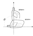
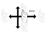
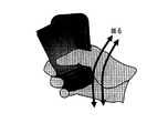
- the attitude state of the communication terminal refers to the attitude state of the communication terminal. For example, as shown in FIG. 2, the inclination of the communication terminal A with respect to the reference axis when the axis oriented in the vertical direction from the ground is used as a reference, and the communication terminal A is swung up, down, left and right as shown in FIG. It means state.
- the posture state detection units 1 1 and 1 2 may be inside or outside the communication terminals A and B.
- the relationship calculation unit 2 calculates the relationship between the posture states of the communication terminals A and B based on the posture states of the communication terminals detected by the posture state detection units 1 1 and 1 2 .
- the relationship between posture states refers to the relationship between posture states between communication terminals.
- the attitude state of the communication terminal is the inclination of the communication terminal
- the relationship between the attitude states is an angle formed between the communication terminals A and B as shown in FIG.
- the posture state of the communication terminal is a change in acceleration
- the relationship between the posture states is, for example, the number of times each terminal is swung between the communication terminals A and B as shown in FIG.
- the relationship calculation unit 2 may be provided in at least one of communication terminals that perform communication, or may be provided in an external server that can communicate with the communication terminal.
- the communication policy determination unit 3 determines a communication policy for communication between the communication terminals A and B based on the posture state relationship calculated by the relationship calculation unit 2.
- the communication policy includes a disclosure level, anonymity level, an expiration date, and a disclosure range of information to be transmitted to a communication partner. Moreover, it is good also as one communication policy combining those things.
- the disclosure level is a level to which the user information is disclosed. For example, only “name”, “name and phone number”, “name, phone number and e-mail address”, etc. It is the range to disclose.
- the anonymous level refers to the range of users or communication terminals that can use the newly generated contact address.
- examples of the anonymous level include real name communication, kana communication, and anonymous communication.
- the contact address can be used at any communication terminal.
- the contact address can be used in the group to which the communication terminal of the other party that notified the contact address belongs, but the use of the communication terminal that does not belong to the group is restricted.
- the contact address can be used only by the communication terminal of the other party who has notified the contact address.
- the expiration date is, for example, a period during which communication with the communication terminal of the communication partner can be performed, or an expiration date of information transmitted to the communication partner.
- the disclosure range is the disclosure range of information to be transmitted.
- the communication policy determination unit 3 has a correspondence table between the communication policy and the posture state relationship as described above, and determines a communication policy corresponding to the posture state relationship.
- FIG. 6 is an example of a correspondence table, in which posture state relationships (angles) are associated with communication policies (disclosure levels). For example, when the posture state relationship (angle) is 90 degrees, the name and the mail address are determined as the communication policy (disclosure level).
- the communication policy determination unit 3 may be provided in at least one of communication terminals that perform communication, and may be provided in an external server that can communicate with the communication terminal.
- a communication policy when communicating between communication terminals, a communication policy can be determined without requiring complicated processing at the communication terminals.
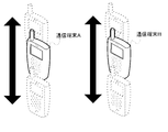
- First Embodiment> a case will be described in which two mobile phones are shaken together, and the disclosure level (disclosure level) of data exchanged between the two mobile phones is changed depending on the number of shakes. Specifically, an example of sending a name to the other party's mobile phone after shaking the mobile phone three times together, name and phone number after shaking the phone seven times, and name, phone number and email address after shaking 15 times is explained. To do.
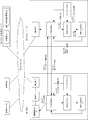
- FIG. 7 is a block diagram showing a configuration example of the first embodiment.
- FIG. 7 there are a mobile phone A and a mobile phone B owned by different users who are subscribed to a communication carrier.
- the mobile phones A and B include a short-range communication unit 11 that communicates with a nearby mobile phone without going through a network, an acceleration sensor 12 that acquires the acceleration of the mobile phone, and values of the acceleration sensor of the mobile phone and the short-range Together with the vibration detection unit 13 that compares the value of the acceleration sensor of the mobile phone of the communication partner received by the communication unit 11 and calculates the number of times the mobile phone and the communication partner mobile phone are shaken together.
- a transmission data determination unit 14 that stores transmission data corresponding to the number of times of shaking, determines transmission data corresponding to the number of times of shaking, and a data storage unit 15 that stores data received from a communication partner. Have.
- the acceleration sensor 12 corresponds to a posture state detection unit
- the vibration detection unit 13 corresponds to a relationship calculation unit
- the transmission data determination unit 14 corresponds to a communication policy determination unit.
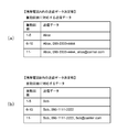
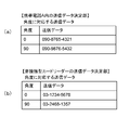
- FIG. 8 is an example of a data table stored in each transmission data determination unit 14 of the mobile phones A and B.
- FIG. 8A is a data table stored in the transmission data determination unit 14 of the mobile phone A.
- FIG. 8B is a data table stored in the transmission data determination unit 14 of the mobile phone B.
- the range of the number of vibrations calculated by the vibration detection unit 13 and transmission data corresponding to the number of vibrations are stored in association with each other. For example, in the data table stored in the transmission data determination unit 14 of the mobile phone B shown in FIG.
- the name “Bob” is associated with the case where the number of vibrations is 1 to 5 times, and the vibration When the number of times is 6 to 10, the name “Bob” and the telephone number “090-1111-2222” are associated with each other, and when the number is the 11th and subsequent times, the name “Bob”, the telephone number “090-1111-2222” and The mail address “bob@carrier.com” is associated.
- the value of the acceleration sensor is transmitted from the acceleration sensor 12 in the mobile phone A to the short-range communication unit 11 (Step 101 in FIG. 7). Whether the mobile phone owner activates a dedicated application or the like, or the timing at which the near field communication unit senses that the communication partner is nearby, the value of the acceleration sensor is the threshold value (intentional by humans). It is also possible that the timing exceeds a threshold value (recognizable that the mobile phone is shaken by the user).
- the mobile phone A transmits the acquired acceleration sensor value from the short-range communication unit 11 to the mobile phone B (Step 102 in FIG. 7).
- the mobile phone B receives the value of the acceleration sensor of the mobile phone A from the short-range communication unit 11 and transmits it to the vibration detection unit 13 (Step 103 in FIG. 7).
- the value of the acceleration sensor of the mobile phone B is transmitted from the acceleration sensor 12 in the mobile phone B to the short-range communication unit 11 (Step 104 in FIG. 7).
- the vibration detection unit 13 of the mobile phone B compares the value of the acceleration sensor of the mobile phone A and the value of the acceleration sensor of the mobile phone B to determine whether or not they are shaken together (whether or not they are synchronized). Judgment), and the number of times of shaking together (hereinafter, the number of times of vibration) is calculated.
- the vibration counts of the mobile phones A and B are both “6”, so the vibration detection unit 13 of the mobile phone B It is detected that the number of times is “6”. Then, the number of vibrations “6” is transmitted to the transmission data determination unit 14 of the mobile phone B (Step 105 in FIG. 7).
- the transmission data determination unit 14 of the mobile phone B determines transmission data to be transmitted to the partner mobile phone based on the stored data table.
- the number of vibrations received from the vibration detection unit 13 of the mobile phone B is “6”, and therefore, according to the example of the data table of FIG.
- the transmission data is a name “Bob” and a telephone number “090-1111-2222”. Therefore, the transmission data determination unit 14 of the mobile phone B transmits the name “Bob” and the telephone number “090-1111-2222” to the short-range communication unit 11 (Step 106 in FIG. 7).
- the short-range communication unit 11 of the mobile phone B transmits the name “Bob” and the phone number “090-1111-2222” to the mobile phone A (Step 107 in FIG. 7).
- the short-range communication unit 11 of the mobile phone A receives the name “Bob” and the telephone number “090-1111-2222” and stores them in the data storage unit 15 (Step 108 in FIG. 7).
- data based on the communication policy may be transmitted from the mobile phone A to the mobile phone B.
- the mobile phone A performs the same operation as the mobile phone B.
- the mobile phone A and the mobile phone B may perform the same process and exchange data.
- the operation order of the mobile phone A and the mobile phone B may be the mobile phone A first or the mobile phone B first, or may be processed simultaneously.
- the mobile phone A may receive data from the mobile phone B
- the mobile phone B may receive data from the mobile phone A
- a confirmation unit may be provided to confirm that the mutual data has been exchanged.
- the second embodiment is an example in which a telephone number is exchanged by holding a mobile phone at an angle to a fixed contactless card reader. That is, in this embodiment, an example in which the telephone number to be exchanged is changed according to the angle formed by the contactless card reader and the mobile phone will be described. For example, when the mobile phone is 2in1, the number is switched between an angle of 0 degrees and an angle of 90 degrees.
- FIG. 10 is a block diagram showing a configuration example of the second embodiment.
- a mobile phone A, a contactless card reader C, a card reader management server D, a telephone E, and a call server F owned by a user who subscribes to a communication carrier are connected via a network. Connected.
- the mobile phone A includes a short-range communication unit 41 that communicates with a nearby contactless card reader C without going through a network, a gyro sensor 42 that detects the tilt of the mobile phone A, and a gyro sensor in the mobile phone A.
- the mobile phone A and the contactless card are determined from the inclination of the mobile phone A and the contactless card reader C by comparing the value with the value of the gyro sensor of the contactless card reader C received by the short-range communication unit 41.
- An angle detection unit 43 that calculates an angle formed by the reader C, a transmission data determination unit that stores transmission data corresponding to the angle formed by the mobile phone A and the contactless card reader C, and determines data corresponding to the angle 44, a telephone directory storage unit 45 that stores received data, a communication unit 46 that performs communication via a network, and a call unit 47 that performs a call.
- FIG. 11 is an example of a data table stored in each transmission data determination unit of the mobile phone A and the contactless card reader C.
- FIG. 11A is stored in the transmission data determination unit 44 of the mobile phone A.
- FIG. 11B is a data table stored in the transmission data determination unit 54 of the contactless card reader C.
- the data table in FIG. 11 stores the angle calculated by the angle detection unit and the telephone number in association with each other.
- the case where the angle is 0 degree and the telephone number “090-8765-4321” are associated with each other.
- the telephone number “090-9987-5432” is associated with the case where the angle is 90 degrees. Note that this data (telephone number) is a valid telephone number that is in a state where it is possible to make a call by making a contract with a communication carrier.
- the non-contact type card reader C includes a short-range communication unit 51 that communicates with a nearby mobile phone A without going through a network, a gyro sensor 52 that detects the inclination of the non-contact type card reader C, and a non-contact type card reader.
- the value of the gyro sensor in C and the value of the gyro sensor of the mobile phone A received by the short-range communication unit 51 are compared, and the mobile phone A and the non-contact type card reader C are compared with each other from the inclination of the mobile phone A and the non-contact card reader C.
- An angle detection unit 53 that calculates an angle formed by the contact type card reader C, transmission data corresponding to an angle formed by the mobile phone A and the non-contact type card reader C are stored, and transmission that determines data corresponding to the angle is transmitted. It has the data determination part 54 and the communication part 55 which communicates via a network.
- the card reader management server D has a communication unit 61 and a phone book storage unit 62, and stores the reception data of the mobile phone A from the non-contact type card reader C in the phone book storage unit 62 by the communication unit 61.
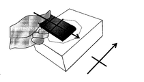
- FIG. 12 shows an example in which the mobile phone A and the contactless card reader C are held at an angle.
- the angle is 90 degrees.
- FIG. 12 a case where the mobile phone A is held at an angle of 90 degrees with respect to the non-contact card reader C will be described. Further, it is assumed that the telephone E is possessed by an administrator of the card reader management server C.
- the value of the gyro sensor 42 is transmitted from the gyro sensor 42 in the mobile phone A to the short-range communication unit 41.
- the transmission timing may be the timing when the owner of the mobile phone A activates an application or the like, or the timing when the near field communication unit 41 senses that the communication partner is nearby.
- the gyro sensor 51 of the non-contact card reader C is also activated to transmit the value to the short-range communication unit (Step 201 in FIG. 10).
- the value received from the gyro sensor 41 of the mobile phone A is transmitted from the short-range communication unit 41 of the mobile phone A to the short-range communication unit 51 of the contactless card reader C (Step 202 in FIG. 10).
- the received value of the gyro sensor of the mobile phone A is transmitted from the short-range communication unit 51 of the non-contact card reader C to the angle detection unit 53 (Step 203 in FIG. 10).
- the value of the gyro sensor is transmitted from the gyro sensor 52 of the non-contact type card reader C to the angle detection unit 53.
- the transmission timing may be the timing at which the value of the gyro sensor is received from the mobile phone A, or the data may always be transmitted at regular intervals (Step 204 in FIG. 10).
- the angle detection unit 53 of the non-contact card reader C compares the value of the gyro sensor of the mobile phone A with the value of the gyro sensor of the non-contact card reader C. The angle formed by is calculated. Here, the angle calculated by the angle detection unit 53 is “90”. The angle detection unit 53 transmits the calculated angle “90” to the transmission data determination unit 54 (Step 205 in FIG. 10).
- the transmission data determination unit 54 of the non-contact type card reader C searches from a data table storing data corresponding to the angle “90” received from the angle detection unit 53.
- the data corresponding to the angle “90” is “03-2468-1357”. Therefore, the transmission data determination unit 54 determines the data to be transmitted as “03-2468-1357”. Then, the determined data “03-2468-1357” is transmitted from the transmission data determination unit 54 to the short-range communication unit 51 (Step 206 in FIG. 10).
- the determined data “03-2468-1357” is transmitted from the non-contact card reader C to the short-range communication unit 41 of the mobile phone A (Step 207 in FIG. 10).
- the short-range communication unit 41 of the mobile phone A receives “03-2468-1357” from the non-contact card reader C and transmits data “03-2468-1357” to the telephone directory storage unit 45. Then, the data “03-2468-1357” is stored in the telephone directory storage unit 45 (Step 208 in FIG. 10).
- the value of the gyro sensor is transmitted from the gyro sensor 52 in the non-contact type card reader C to the short-range communication unit 51 (Step 301 in FIG. 13).
- the value received from the gyro sensor of the non-contact type card reader C is transmitted from the non-contact type card reader C to the mobile phone A (Step 302 in FIG. 13).
- the received value of the gyro sensor of the non-contact card reader C is transmitted from the short-range communication unit 41 of the mobile phone A to the angle detection unit 43 (Step 303 in FIG. 13).
- the value of the gyro sensor is transmitted from the gyro sensor 42 of the mobile phone A to the angle detection unit 43 (Step 304 in FIG. 13).
- the angle detection unit 43 compares the value of the gyro sensor of the mobile phone A with the value of the gyro sensor of the non-contact type card reader C, and calculates the angle formed by the non-contact type card reader C and the mobile phone A.
- the angle calculated by the angle detection unit 43 is “90”.
- the angle detection unit 43 transmits the calculated angle “90” to the transmission data determination unit 44 (Step 305 in FIG. 13).
- the transmission data determination unit 44 searches from a data table storing data corresponding to the angle “90” received from the angle detection unit 43.
- the data corresponding to the angle “90” is “090-9987-5432”. Therefore, the transmission data determination unit 44 determines the data to be transmitted as “090-9876-5432”. Then, the determined data “090-9987-5432” is transmitted from the transmission data determining unit 44 to the short-range communication unit 41 (Step 306 in FIG. 13).
- the determined transmission data “090-9876-5432” is transmitted from the mobile phone A to the short-range communication unit 51 of the contactless card reader C (Step 307 in FIG. 13).
- the short-range communication unit 51 of the non-contact type card reader C transmits the received data “090-9876-5432” to the communication unit 55 (Step 308 in FIG. 13).
- the communication unit 55 of the non-contact type card reader C transmits the data “090-9987-5432” determined by the mobile phone A to the communication unit 61 of the card reader management server E (Step 309 in FIG. 13).
- the communication unit 61 of the card reader management server E transmits the received data “090-9876-5432” to the telephone directory storage unit 62.
- the received data “090-9987-5432” is stored in the telephone directory storage unit 62 (Step 310 in FIG. 13).
- the calling unit 47 of the mobile phone A makes a request for acquiring the telephone number acquired from the contactless card reader C to the telephone directory storage unit 45 (Step 401 in FIG. 14).
- the telephone directory storage unit 45 transmits the telephone number “03-2468-1357” acquired from the stored contactless card reader C to the calling unit 47 (Step 402 in FIG. 14).
- a call request (section establishment request) is made from the call unit 47 to the communication unit 46 through the call server F using the telephone number “03-2468-1357” (Step 403 in FIG. 14).
- the telephone number “03-2468-1357” is received by the telephone E assigned by the communication carrier (Step 404 in FIG. 14).
- the order of the operation of the mobile phone A and the non-contact card reader C may be the mobile phone A first, the non-contact card reader C first, or may be processed simultaneously.
- the mobile phone A receives data from the contactless card reader C
- the contactless card reader C receives data from the mobile phone A
- a unit is provided for confirming that the data has been exchanged.
- the data may be stored after the data exchange is confirmed.
- it can be used for a service for exchanging information between a mobile phone storing a plurality of credit numbers and a contactless card reader.
- a credit number selected according to the angle between the mobile phone and the contactless card reader is transmitted from the mobile phone to the contactless card reader, and each credit type is transmitted from the contactless card reader to the mobile phone.
- the third embodiment is an example in which a communication policy is determined according to an angle formed by two mobile phones, and a contact address based on the communication policy is generated.
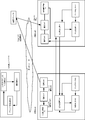
- FIG. 15 is a block diagram showing a configuration example of the third embodiment.
- a mobile phone A and a mobile phone B, a pseudonym communication server G, and a call server H owned by a user who subscribes to a communication carrier are connected via a network. Since the mobile phone A and the mobile phone B are the same as those in the above-described embodiment, detailed description thereof is omitted.
- the kana communication server G includes a communication unit 91 that communicates with other communication devices via a network, An angle formed by the mobile phone A and the mobile phone B and a policy corresponding to the angle are stored, a policy determining unit 92 for determining a policy corresponding to the angle, and a contact address corresponding to the policy determined by the policy determining unit 92 And a contact address generation unit 93 for generating.
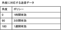
- FIG. 16 is an example of a data table stored in the policy determining unit 92.
- the angle (angle formed by the mobile phone A and the mobile phone B) calculated by the angle detection unit and the policy item are stored in association with each other. For example, in FIG. 16, the angle is associated with 0 degree and valid for 1 hour, the angle is associated with 90 degree and a policy that is valid for 3 days, and the angle is associated with 180 degree and a policy that is valid for 1 week. It has been.
- FIG. 17 shows a state where the angle formed by the two mobile phones A and B is 90 degrees.
- the contact address is paid out to the mobile phone A.
- the value of the gyro sensor is transmitted from the gyro sensor 42 in the mobile phone A to the short-range communication unit 41 (Step 501 in FIG. 15).
- the short-range communication unit 41 of the mobile phone A transmits the value received from the gyro sensor of the mobile phone A, the user identifier [user001] of the owner of the mobile phone A, and the mobile phone B (Step 502 in FIG. 15).
- the short-range communication unit 41 of the mobile phone B transmits the received value of the gyro sensor of the mobile phone A and the user identifier [user001] of the mobile phone A to the angle detection unit 43 (Step 503 in FIG. 15).
- the gyro sensor 42 of the mobile phone B transmits the value of the gyro sensor to the angle detection unit 43 (Step 504 in FIG. 15).
- the angle detection unit 43 of the mobile phone B compares the value of the gyro sensor of the mobile phone A and the value of the gyro sensor of the mobile phone B, and calculates the angle formed by the mobile phone A and the mobile phone B.
- the angle detection unit 43 calculates the angle “90”.
- the angle detection unit 43 transmits the calculated angle “90” and the user identifier [user001] of the mobile phone A to the communication unit 46 (Step 505 in FIG. 15).
- the communication unit 46 of the mobile phone B transmits the angle “90”, the user identifier [user001] of the mobile phone A, and the user identifier [user002] of the mobile phone B to the communication unit G of the pseudonym communication server (FIG. 15). Step 506).
- the communication unit 91 of the pseudonym communication server G transmits the received angle “90”, the user identifier [user001] of the mobile phone A, and the user identifier [user002] of the mobile phone B to the policy determining unit 92 (FIG. 15). Step 507).
- the policy determination unit 92 of the Kana communication server G searches the data table for the policy corresponding to the angle “90”, and determines that the policy corresponding to the angle “90” is “3 days valid”. Then, the policy determination unit 92 transmits the policy “valid for 3 days”, the user identifier [user001], and the user identifier [user002] to the contact address generation unit 93 (Step 508 in FIG. 15).
- the contact address generation unit 93 of the pseudonym communication server G generates a telephone number that is valid for three days, for example “03-9999-9999”, between the received user identifier [user001] and user identifier [user002]. Then, the contact address generation unit 93 transmits the generated telephone number “03-9999-9999” to the communication unit 91 (Step 509 in FIG. 15).
- the communication unit 91 of the pseudonym communication server G transmits the generated telephone number “03-9999-9999” to the communication unit 46 of the mobile phone A (Step 510 in FIG. 15).
- the communication unit 46 of the mobile phone A transmits the received telephone number “03-9999-9999” to the telephone directory storage unit 45, and the telephone number “03-9999-9999” is stored in the telephone directory storage unit 45 ( Step 511 in FIG. 15).
- the mobile phone A and the phone number valid for 3 days are also stored in the phone book storage unit 45 of the mobile phone B by the same operation as described above.
- the telephone number “03-9999-9999” of the mobile phone B is acquired from the phone book storage unit 45 of the mobile terminal A (Step 512 in FIG. 18).
- the call unit 46 of the mobile terminal A requests the communication unit 45 to establish a session for a call (Step 513 in FIG. 18).
- a call request is made from the communication unit 45 of the mobile phone A to the call server H (Step 514 in FIG. 18).
- the mobile phone A receives a call from the mobile phone A (Step 515 in FIG. 18).
- the third embodiment it is possible to determine a communication policy only by performing a simple operation of performing communication by tilting user terminals in arbitrary directions. Therefore, it is possible to easily pay out a kana contact address whose kana level such as anonymous / kana / real name can be changed with other users.
- the number of users of the pseudonym communication system is expected to increase, and the number of customers and the market will be expanded because the user operations at the time of paying out the contact address are simplified.
- the anonymity level is determined corresponding to the number of times two mobile phones are shaken, as in the first embodiment.
- the anonymous level is defined as the range of users or communication terminals that can use the newly generated contact address.
- the contact address for real name communication can be used at any communication terminal, and the contact address for kana communication is used within the group to which the communication terminal of the other party that notified the contact address belongs.
- the use of communication terminals that do not belong to the group shall be restricted, and the contact address of anonymous communication shall be controlled so that it can be used only by the communication terminal of the other party that notified the contact address. .
- a contact address paid out to a specific service provider for example, an employee of a restaurant, can be controlled so that it can be used by communication terminals of all employees belonging to the restaurant.
- FIG. 19 shows a block diagram of the fourth embodiment.
- the difference from the block diagram of the third embodiment is that the cellular phone A and the cellular phone B are provided with a policy determining unit 130 instead of the policy determining unit 92 in the kana communication server.
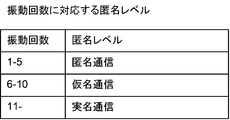
- FIG. 20 is a diagram illustrating an example of a data table stored in the policy determination unit 130 according to the fourth embodiment.
- the data table shown in FIG. 20 has a policy item relating to the anonymous level corresponding to the number of vibrations calculated by the vibration detection unit. For example, if the number of vibrations is 1 to 5, the policy is anonymous communication, if the number of vibrations is 6 to 10 times, the policy is kana communication, and if the number of vibrations is 11 times or more, the policy is real name communication. Is shown.
- the operation of the fourth embodiment will be described with a focus on differences from the operation example of the third embodiment with reference to FIG.
- the operation of paying out the kana contact address from the mobile phone B to the mobile phone A will be described.
- the acceleration sensor 12 of the mobile phone A detects the value of the sensor of the mobile phone A and transmits this value to the short-range communication unit 41 (Step 601 in FIG. 19).
- the short-range communication unit 41 transmits the value received from the acceleration sensor of the mobile phone A and the user identifier [user001] of the owner of the mobile phone A to the mobile phone B (Step 602 in FIG. 19).
- the short-range communication unit 41 of the mobile phone B transmits the received value of the acceleration sensor of the mobile phone A and the user identifier [user001] of the mobile phone A to the vibration detection unit 13 (Step 603 in FIG. 19).
- the value of the acceleration sensor is transmitted from the acceleration sensor 12 of the mobile phone B to the vibration detection unit 13 (Step 604 in FIG. 19).
- the vibration detection unit 13 of the mobile phone B compares the value of the acceleration sensor of the mobile phone A and the value of the acceleration sensor of the mobile phone B, and calculates the number of vibrations. Here, the calculated number of vibrations is 7 times. Then, the calculated vibration count “7” and the user identifier [user001] of the mobile phone A are transmitted from the vibration detection unit 13 to the policy determination unit 130 (Step 605 in FIG. 19).
- the policy determination unit 130 of the mobile phone B searches the stored data table for the anonymous level “kana communication” corresponding to the vibration frequency “7”, and determines the policy as the anonymous level “kana communication”.
- the policy determination unit 130 transmits the anonymous level “kana communication” and the user identifiers [user001] and [user002] to the communication unit (Step 606 in FIG. 19).
- the communication unit of the mobile phone B transmits the anonymous level “kana communication”, the user identifier [user001] of the mobile phone A, and the user identifier [user002] of the mobile phone B to the communication unit of the kana communication server (FIG. 19). (Step 607).
- the communication unit 91 of the kana communication server transmits the anonymous level “kana communication”, the user identifier [user001] of the mobile phone A, and the user identifier [user002] of the mobile phone B to the contact address generation unit (Step 608 in FIG. 19). ).
- the contact address generator 93 of the kana communication server generates a contact address based on the received anonymous level “kana communication”.
- the contact address generation unit transmits the generated contact address to the communication unit (Step 609 in FIG. 19).
- the communication unit 91 in the kana communication server transmits the generated contact address to the communication unit of the mobile phone A (Step 610 in FIG. 19).
- the communication unit 46 of the mobile phone A transmits the received contact address to the phone book storage unit, and the received contact address is stored in the phone book storage unit (Step 611 in FIG. 19).
- the operation of paying out the kana contact address to the mobile phone B is the same.
- either the contact address payout to the mobile phone A or the contact address payout to the mobile phone B may be performed first or may be processed simultaneously.
- the fourth embodiment it is possible to determine a communication policy simply by shaking a user terminal together. Therefore, it is possible to easily pay out a kana contact address whose kana level such as anonymous / kana / real name can be changed with other users.
- the number of users of the pseudonym communication system is expected to increase, and the number of customers and the market will be expanded because the user operations at the time of paying out the contact address are simplified.
- the effect of the service provider is that the user can easily use the temporary anonymous contact address, the use of the service by the real name is reduced, and the cost of protecting the personal information of the service provider is reduced. .
- FIG. 21 is a block diagram illustrating a configuration example of the fifth embodiment.
- a user terminal 100 such as a mobile phone or a PDA owned by a user who subscribes to a communication carrier, a user terminal 200, a pseudonym communication server 300 that performs communication reflecting a policy, and a communication business
- the communication confirmation server 400 owned by the person is connected via a network.
- the communication carrier is a company that provides telecommunication services such as fixed telephones and mobile phones.
- a communication unit 110 that performs communication via a network
- an acceleration sensor 120 that acquires the acceleration and rotation angle of the user terminal
- short-range communication that performs communication with a nearby user terminal without via a network Unit 130
- an angle detection unit 140 for obtaining an angle between user terminal 100 and communication partner user terminal 200 from the value of the acceleration sensor in user terminal 100 and the value of the acceleration sensor of the communication partner obtained from short-range communication unit 130
- a correspondence table of angles and kana levels (anonymous / kana / real name) is stored
- a policy determination unit 150 that determines a communication policy according to the angle, and a telephone directory that stores contact names and contact names.
- the value detected by the acceleration sensor represents the inclination of the user terminal.
- Tilt is based on an axis that is perpendicular to the ground, and the terminal is tilted 90 degrees when the terminal is tilted from the left shoulder to the right shoulder, 180 degrees when the terminal is tilted head or down, and from the right shoulder When the terminal is tilted toward the left shoulder, the tilt is set to 270 degrees.
- FIG. 22 shows the inclination of the user terminal, where 1010 is 0 degrees, 1020 is 90 degrees, 1030 is 180 degrees, and 1040 is 270 degrees.
- the angle detection unit 140 may be in a user terminal or in a server via a network.
- FIG. 23 is an example of a correspondence table stored in the policy determination unit 150, which includes items of a detection angle calculated by the angle detection unit 140 and a communication policy corresponding to the angle, and a communication policy for each angle. Are listed. For example, 1510 indicates that real name communication is performed when the angle is 180 degrees.
- Real name communication is to communicate with real name.
- the real name is a number that can identify an individual obtained by presenting his / her real name such as his / her home phone number or mobile phone number, his / her home address, his / her office, etc.
- Kana communication is to communicate with a communication partner using a contact address other than the real name generated before. For example, it includes a mail address acquired without charge that can be easily acquired without presenting a real name, a home address, etc. without including personally identifiable information and can be easily discarded.
- Anonymous communication is to communicate with the other party using a contact address that cannot identify an individual. Different contact addresses are generated when communicating with different communication partners.
- the communication policy of the correspondence table in the policy decision unit 150 may include not only the kana level but also the expiration date of the contact address of the kana, the invalid / valid condition, the number of times it can be used, and the like.
- the user may freely set the expiration date / valid number of the contact address.
- the correspondence table may be managed on the network instead of the policy determination unit in the user terminal.
- FIG. 24 is an example in which the number of possible incoming calls for each user identifier is described in addition to the angle and the kana level.
- 1511 indicates that the number of possible incoming calls when performing real name communication at an angle of 180 degrees is unlimited.
- Reference numeral 1512 denotes that the number of incoming calls is 90 when the kana communication is performed at an angle of 90 degrees.
- 1513 indicates that the number of incoming calls when anonymous communication is performed at an angle of 0 degrees is five.
- the user terminal 200 is configured similarly to the user terminal 100.
- the kana communication server 300 includes a communication unit 310 that performs communication via a network, and a contact address generation unit 320 that generates a contact address according to an anonymous level.
- the communication confirmation server 400 includes a communication unit 410 that performs communication via a network, and a communication setting confirmation unit 420 that confirms that communication from both users has been received based on data received by the communication unit 410. .
- the user identifier is a value for the communication company to identify the user or the user terminal. For example, in the case of a mobile phone, a telephone number is applicable.
- each user has one user terminal, and user A is assigned a user identifier “user001” by a communication carrier and possesses the user terminal 100. Similarly, it is assumed that the user B has the user terminal 100 with the user identifier “user002”.
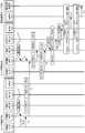
- FIG. 25 and FIG. 26 are sequence diagrams showing an example of the operation of the fifth embodiment.
- User A and user B signal and operate the user terminal, and the short-range communication unit 130 of the user terminal 100 and the short-range communication unit 230 of the user terminal 200 start communication (A1, A2 in FIG. 25). In addition, it may be used as a trigger for starting near field communication that the value of the acceleration sensor exceeds a set threshold value. Then, the user terminal 100 and the user terminal 200 are overlapped with an arbitrary inclination. In the following description, a case will be described in which the terminal is tilted from the left shoulder to the right shoulder with the inclination of the user terminal 100 being 0 degrees and the inclination of the user terminal 200 being 90 degrees with reference to an axis that is directed vertically from the ground.
- the near field communication unit 130 acquires the value “0 degree” of the acceleration sensor, which is the inclination of the user terminal, from the acceleration sensor 120 (A3 in FIG. 25).
- the short-range communication unit 130 that has received the value “0 degree” of the acceleration sensor transmits the value “0 degree” of the acceleration sensor and the user identifier “user001” to the short-range communication unit 230 in the user terminal 200 (FIG. 25). A4).
- the short-range communication unit 230 in the user terminal 200 that has received the data “0 degree” and the user identifier “user001” of the acceleration sensor 120 transfers the data to the angle detection unit 240 (A5 in FIG. 25).
- the value “90 degrees” acquired by the acceleration sensor 220 of the user terminal 200 and the user identifier “user002” are transmitted to the angle detection unit 240 (A6 in FIG. 25).
- the angle detection unit 240 that receives the acceleration “0 degrees” and the user identifier “user001” of the user terminal 100 and the acceleration “90 degrees” and the user identifier “user002” of the user terminal 200 receives the user terminal 100 from the value of the acceleration sensor.
- 90 degrees is calculated (A7 in FIG. 25).
- the angle detection unit 240 transmits the calculated value “90 degrees” and the user identifier “user001” of the user terminal 100 to the policy determination unit 250 (A8 in FIG. 25).
- the policy determining unit 250 Upon receiving the angle “90 degrees”, the policy determining unit 250 determines the communication policy corresponding to the angle as “kana communication” from the correspondence table 1520 of FIG. 22, and transmits the determined communication policy to the communication unit 210 (FIG. 25). A9).
- the communication unit 210 that has received the communication policy “kana communication” transmits the user identifier “user002” of the user terminal B, the communication partner user identifier “user001”, and the communication policy “kana communication” within the communication confirmation server 400. It transmits to the part 410 (A10 of FIG. 25).
- the communication unit 410 that has received the communication policy “kana communication”, the user identifier “user001” on the policy setting side, and the communication partner user identifier “user002” sets the communication policy “kana” to the communication setting confirmation unit 420.
- Communication is transmitted (A11 in FIG. 25).
- the value “90 degrees” acquired by the acceleration sensor 120 in the user terminal 200 is notified to the short-range communication unit 230 (A12 in FIG. 26).
- the short-range communication unit 230 that has received the value “90 degrees” of the acceleration sensor transmits the value “90 degrees” of the acceleration sensor together with the user identifier “user002” to the short-range communication unit 130 in the user terminal 100 (FIG. 26). A13).
- the short-range communication unit 130 in the user terminal 100 that has received the data “90 degrees” and the user identifier “user002” of the acceleration sensor 220 transfers the data to the angle detection unit 140 (A14 in FIG. 26).
- the acceleration sensor 120 of the user terminal 100 transmits the acquired value “0 degree” and the user identifier “user001” to the angle detection unit 140 (A15 in FIG. 26).
- the angle detection unit 140 that receives the acceleration “0 degrees” and the user identifier “user001” of the user terminal 100 and the acceleration “90 degrees” and the user identifier “user002” of the user terminal 200 receives the mobile terminal A from the value of the acceleration sensor. 26 is calculated as follows:
- 90 degrees (A16 in FIG. 26).
- the angle detection unit 140 transmits the calculated value “90 degrees” and the user identifier “user002” to the policy determination unit 150 (A17 in FIG. 26).
- the policy determining unit 150 determines the communication policy corresponding to the angle as “kana communication” from 1520 in FIG. 23, and transmits the determined communication policy “kana communication” to the communication unit 110 ( A18 in FIG.
- the communication unit 110 that has received the communication policy “kana communication” transmits the user identifier “user001” of the mobile terminal A, the user identifier of the communication partner “user002”, and the communication policy “kana communication” to the communication unit in the communication confirmation server 400. 410 (A19 in FIG. 26).
- the communication unit 410 that has received the communication policy “kana communication”, the user identifier “user001” of the transmission side that sets the policy, and the user identifier “user002” of the communication partner sets the communication policy “kana communication” to be set in the communication confirmation unit 420. Transmit (A20 in FIG. 26).
- A3 to A11 and A12 to A20 may be performed simultaneously, the order may be reversed, or only A1 to A11 or only A1 to A2 and A12 to A20 may be used.
- the communication setting confirmation unit 420 confirms that the communication policy has been received from both the user identifier “user001” and the user identifier “user002” (A21 in FIG. 26).
- the communication setting confirmation unit 420 that has confirmed reception of the communication policy transmits the user identifiers “user001” and “user002” and the determined communication policy “kana communication” to the contact address generation unit 320 of the kana communication server (FIG. 26). A22, A23).
- the contact address generation unit 320 Upon receiving the user identifiers “user001” and “user002” and the communication policy “kana communication”, the contact address generation unit 320 receives the kana contact address “kamei111@nec.com” of the user identifier “user001” and the user identifier “user002”. "Kamei222@nec.com” is generated. In addition, the generated contact address of the pseudonym generates one contact address that can be made / received in accordance with a policy such as the effective number specified by the user identifier “user001” and the user identifier “user002” in addition to the pseudonym level. It doesn't matter.
- the contact address generation unit 320 notifies the user identifier “user002” of the generated pseudonym contact address “kamei111@nec.com” via the communication unit 310. Then, the communication unit 210 of the user terminal 200 stores the received contact address “kamei111@nec.com” in the telephone directory 260 in the user terminal 200 (A24, A25, A26 in FIG. 26).
- the contact address generation unit 320 notifies the user identifier “user001” of the generated pseudonym contact address “kamei222@nec.com” via the communication unit 310. Then, the communication unit 110 of the user terminal 100 stores the received contact address “kamei222@nec.com” in the telephone directory 160 in the user terminal 100 (A24, A27, A28 in FIG. 26).
- the notification of the kana contact address does not matter.
- the notified contact address may or may not be registered in the phone book.
- the user terminal 100 with the user identifier “user001” contacts the user identifier “user002” using the kana contact address “kamei222@nec.com”.
- the user terminal 100 with the user identifier “user001” sends an email to the user identifier “user002”
- the user identifier “user001” is transmitted as “TO: kamei222@nec.com, FM: user001”.
- the kana communication server 400 converts “kamei222@nec.com” into “user002”, converts “user001” into “kamei111@nec.com”, and transmits the mail.
- the user terminal 200 with the user identifier “user002” receives a mail “TO: user002, FM: kamei111@nec.com”.
- the fifth embodiment it is possible to determine a communication policy only by performing a simple operation of performing communication by inclining user terminals in arbitrary directions. Therefore, it is possible to easily pay out a kana contact address whose kana level such as anonymous / kana / real name can be changed with other users.
- the number of users of the pseudonym communication system is expected to increase, and the number of customers and the market will be expanded because the user operations at the time of paying out the contact address are simplified.
- the effect of the service provider is that the user can easily use the temporary anonymous contact address, the use of the service by the real name is reduced, and the cost of protecting the personal information of the service provider can be reduced. .
- the sixth embodiment an example of generating a contact address corresponding to all members of a group selected by the user will be described.
- the restaurant employee wants to contact the user A as soon as the seat is ready, and gives the user A a mobile phone number and the like. There are many cases to ask. However, even if the face is known, the user A does not want to easily tell others the mobile phone number corresponding to the personal information. Therefore, in the sixth embodiment, by using the terminal of the user A and the terminal of the restaurant employee or the terminal dedicated to the restaurant, the user A and the restaurant employee are paid out by paying out an anonymous contact address. Make anonymous communication. Specifically, when the contact address is generated between the user A and the user B who is one restaurant employee, the contact address is made valid between the user A and all the restaurant employees. As a result, all restaurant employees can perform seat guidance when there is no seat available.
- FIG. 27 is a block diagram showing the sixth embodiment.
- each user terminal includes a group information storage unit 700 and a group selection unit 701.
- the group selection unit 701 selects whether the communication address issued from the kana communication server 300 is associated with an individual or with which group.
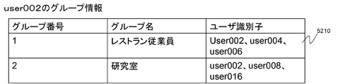
- FIG. 28 is a diagram showing an example of storage contents of the group information storage unit 700 of the user terminal B having the user identifier “user002” held by the user B.
- the group information storage unit 700 as shown in FIG. 28, a group name is assigned for each group number, and user identifiers of users belonging to the group are described. 5210 indicates that the user identifiers “user002”, “user004”, and “user006” belong to the group name “restaurant employee” with the group number “1”.
- the contents of the group information storage unit 700 may be registered as part of the phone book in the user terminal or may be registered as part of the network phone book.
- FIG. 29 is a sequence diagram illustrating an example of an operation according to the sixth embodiment.
- the user identifier “user001” is user A
- the user identifier “user002” is user B
- the user identifier “user004” is user D
- the user identifier “user006” is user F.
- user A owns user terminal A
- user B owns user terminal B
- user D owns user terminal D
- user F owns user terminal F.
- a contact address is generated between the user A and the user B who is one employee of the restaurant, and the user A, the user B who is the employee of the restaurant, the user D, and A case where the contact address is validated with the user F will be described.
- the operations A1 and A2 in the fifth embodiment described above are performed between the user terminal A and the user terminal B.
- the angle formed by the user terminal A and the user terminal B is 90 degrees.
- the operations A3 to A8 in the fifth embodiment are performed between the user terminal A and the user terminal B.
- the policy determination unit 250 determines the communication policy corresponding to the angle as “kana communication” from the correspondence table of FIG.
- the information identifier “1” is transmitted to the group information selection unit 701 (B2 in FIG. 29).
- the group information selection unit 701 of the user terminal B200 transmits the user identifier “user002”, the communication partner user identifier “user001”, the communication policy “kana communication”, and the group identifier “1” to the group information storage unit 700 (FIG. 29 B3).
- the group information storage unit 700 Upon receiving the group identifier “1”, the group information storage unit 700 receives the user identifiers “user002”, “user004” and “user006” corresponding to the group identifier “1”, the user identifier “user001” of the communication partner, and the communication policy. “Kana communication” is transmitted to the communication unit 110 (B4 in FIG. 29).
- the contact address generation unit 320 Upon receiving the user identifiers “user001”, “user002”, “user004”, “user006” and the communication policy “kana communication”, the contact address generation unit 320 receives the contact address “kamei111 @@ corresponding to the user identifier“ user001 ”. nec.com ”and the contact address“ circleA@nec.com ”of the pseudonym corresponding to the user identifiers“ user002 ”,“ user004 ”, and“ user006 ”.
- the contact address “circleA@nec.com” of the pseudonym corresponding to the user identifiers “user002”, “user004”, “user006” is, for example, a mailing list.
- the kana communication server 300 notifies the generated kana contact address “kamei111@nec.com” to the user terminal B of the user identifier “user002” (B5 in FIG. 29).
- the kana communication server 300 notifies the generated kana contact address “kamei111@nec.com” to the user terminal F of the user identifier “user006” (B6 in FIG. 29).
- the kana communication server 300 notifies the generated kana contact address “kamei111@nec.com” to the user terminal D of the user identifier “user004” (B7 in FIG. 29).
- the kana communication server 300 notifies the generated kana contact address “circleA@nec.com” to the user terminal A having the user identifier “user001” (B8 in FIG. 29).
- the policy determined by the policy determination unit 150 is applied. For example, when a contact is made from the user identifier “user004” to the user identifier “user001” using the kana contact address “kamei111@nec.com”, the user terminal D of the user identifier “user004” is the pseudonym and the user identifier “user001”. Is communicated with the user terminal A.
- the sixth embodiment for example, when waiting for a vacant seat in a restaurant or karaoke, it is not necessary to convey the address including the real name to the service provider, and it is difficult to convey such information. Therefore, it is possible to increase the use of users who have not received services until now.
- the seventh embodiment it is automatically determined whether or not the contents of the individual schedule correspond to the group. For example, in an activity time zone such as a circle or a part-time job, an individual works as a member of an organization. Therefore, when “Circle” is described in the user's schedule book, it is obvious that the user has a circle activity. Therefore, by linking the group selection with the scheduler, it is configured to automatically select the group that matches the schedule, and the address of the policy that matches the group that was scheduled according to the schedule is saved. An example in which can be paid out will be described.
- FIG. 30 is a block diagram showing the seventh embodiment.
- a scheduler 705 is provided.
- a schedule is registered for each user identifier as indicated by 5110 in FIG. 5110 is an example of a schedule.
- the user B with the user identifier “user002” indicates that there is a circle recruitment activity from 13:00 to 15:00 on April 12, 2009.
- the part enclosed in parentheses indicates a group identifier.
- An example of a schedule 5110 indicates that the group identifier is “circle”.
- FIG. 32 is a diagram illustrating an example of storage contents of the group information storage unit 700 of the user terminal B having the user identifier “user002” held by the user B according to the seventh embodiment.
- a group name is assigned for each group number, and a user identifier of a user belonging to the group is described.
- Reference numeral 5220 in FIG. 32 indicates that the user identifiers “user002”, “user004”, and “user006” belong to the group name “circle” having the group number “1”.
- FIG. 33 is a sequence diagram illustrating an example of an operation according to the seventh embodiment.
- the user identifier “user001” is user A
- the user identifier “user002” is user B
- the user identifier “user004” is user D
- the user identifier “user006” is user F.
- user A owns user terminal A
- user B owns user terminal B
- user D owns user terminal D
- user F owns user terminal F.
- user B invites user A through a recruitment activity
- user B generates a contact address between user A and user B who is one of the members of the circle, and user A and the user who is a member of the circle A case where the contact address is made valid among B, user D, and user F will be described.
- the operations A1 and A2 in the fifth embodiment described above are performed between the user terminal A and the user terminal B.
- the angle formed by the user terminal A and the user terminal B is 90 degrees.
- Subsequent operations A1 to A8 are the same as those in the fifth embodiment.
- the policy determining unit 150 determines the communication policy corresponding to the angle as “kana communication” from the correspondence table of FIG. 24, and determines the determined communication policy “kana communication” and the user identifier “user002”. Is transmitted to the scheduler (C1 in FIG. 33).
- the scheduler 705 confirms whether or not there is a schedule corresponding to the time “April 12, 2009” at which the user identifier is received in the schedule of the user identifier “user002” (C2 in FIG. 33).
- the schedule of the scheduler 705 stores “13-15 o'clock [Circle] recruitment activity”, so the group identifier “Circle” is transmitted to the group information section (FIG. 33).
- C3 The time may be acquired from a network clock, or the data of the radio clock may be acquired from radio waves.
- the group information storage unit 700 Upon receiving the group identifier “circle”, the group information storage unit 700 transmits the user identifiers “user002”, “user004”, and “user006” corresponding to the group identifier “circle” to the communication unit 110 according to the correspondence table of FIG. (C4 in FIG. 33).
- the seventh embodiment by coordinating with the scheduler, it is possible to pay out a kana address that matches the selected group without the user having to select the group.
- each unit is configured by hardware, but can be configured by a program that causes a CPU or the like to execute the same operation as each unit.
- a communication system having at least two or more communication terminals, Posture state detection means for detecting the posture state of the communication terminal; Relationship calculating means for calculating the relationship of the posture state between the communication terminals based on the posture state of each communication terminal detected by the posture state detecting means; A communication policy determining unit that determines a communication policy to be applied between the communication terminals based on a relationship of attitude states between the communication terminals.
- position state detection means detects the inclination on the basis of the predetermined attitude
- the communication system according to supplementary note 1, wherein the relationship calculation unit calculates an angle formed between the communication terminals based on the inclination of each communication terminal detected by the posture state detection unit.
- position detection means detects the change of the acceleration of a communication terminal
- the communication system according to supplementary note 1, wherein the relationship calculation unit calculates the number of synchronization of operations between the communication terminals based on a change in acceleration of each communication terminal detected by the posture state detection unit.
- the communication system according to any one of supplementary note 1 to supplementary note 3, further comprising: an information determining unit that determines or generates information to be transmitted to at least one communication terminal among the communication terminals based on the communication policy.
- the communication policy is at least one of a disclosure level, an anonymous level, an expiration date, and a disclosure range of information to be transmitted to at least one communication terminal among the communication terminals, or a combination thereof.
- the communication system according to any one of appendix 1 to appendix 4.
- the said communication terminal has the said attitude
- the communication system according to any one of appendix 1 to appendix 6.
- the communication terminal includes the posture state detection unit, a relationship calculation unit that calculates a posture state relationship between the communication terminals, and the communication policy determination unit.
- the communication system according to any one of appendix 1 to appendix 6, wherein a server that communicates with each of the communication terminals includes the information determination unit.
- the first communication terminal is Attitude state detection means for detecting the attitude state of the first communication terminal; A transmitter that transmits the detected attitude state and the identifier of the communication terminal to the second communication terminal;
- the second communication terminal is Posture state detection means for detecting the posture state of the second communication terminal; Relationship calculation for calculating the relationship between the posture state of the first communication terminal and the second communication terminal based on the posture state of the first communication terminal and the posture state of the second communication terminal.
- Communication policy determining means for determining a communication policy to be applied between the first communication terminal and the second communication terminal based on the relationship between the posture states; Transmission means for transmitting the communication policy and the identifiers of the first communication terminal and the second communication terminal to the server; The server Based on the identifiers of the first communication terminal and the second communication terminal and the communication policy, the communication policy is set for communication between the first communication terminal and the second communication terminal.
- a communication system having communication means for setting communication based on the communication.
- the first communication terminal is: Relationship calculation for calculating the relationship between the posture state of the first communication terminal and the second communication terminal based on the posture state of the first communication terminal and the posture state of the second communication terminal.
- the transmission means of the second communication terminal confirms a match between the communication policy from the first communication terminal and the communication policy from the second communication terminal, and if they match, the communication policy and the first
- the communication system according to appendix 9, wherein the communication terminal and the identifier of the second communication terminal are transmitted to the server.
- the second communication terminal is A group table in which an identifier of at least one communication terminal and a group identifier including the identifier of the communication terminal are associated with each other, and a selection unit that selects a group identifier to which the communication policy is applied from the group table,
- the transmission means of the second communication terminal sends the communication policy and the identifiers of the communication terminals included in the group of the first communication terminal, the second communication terminal, and the selected group identifier to the server.
- the communication system according to supplementary note 9 or supplementary note 10, wherein communication based on the communication policy is set for communication between the communication terminal and the communication terminal of the selected group.
- the second communication terminal includes a schedule storage unit that stores a date and time and an identifier of the group corresponding to the date and time, 12.
- position detection means detects the inclination on the basis of the predetermined attitude
- the communication system according to any one of appendix 9 to appendix 12, wherein the relationship calculation unit calculates an angle formed between the communication terminals based on the inclination of each communication terminal detected by the posture state detection unit.
- position state detection means detects the change of the acceleration of a communication terminal
- the relationship calculation means calculates the number of motion synchronization between the communication terminals based on a change in acceleration of each communication terminal detected by the posture state detection means. Communications system.
- Supplementary note 15 Any one of Supplementary note 9 to Supplementary note 14, wherein the communication policy defines at least one of a communication anonymous level, communication expiration date, information disclosure level, information disclosure range, or a combination thereof.
- the communication system according to 1.
- a communication terminal in a communication system having communication policy determining means for determining a communication policy to be applied between the communication terminals based on a relationship of attitude states between the communication terminals, Posture state detection means for detecting the posture state of the communication terminal; A receiving means for receiving an attitude state of a communication partner communication terminal to be a communication partner and an identifier of the communication partner communication terminal; Based on the posture state of the communication terminal and the posture state of the communication partner communication terminal, a relationship calculation means for calculating the relationship of the posture state between the communication terminal and the communication partner communication terminal; A communication terminal comprising: a transmission unit configured to transmit the relationship between the posture states and the identifiers of the own communication terminal and the communication partner communication terminal to the communication policy determination unit.
- a communication terminal in a communication system having communication means for setting communication based on a predetermined communication policy between communication terminals, Posture state detection means for detecting the posture state of the communication terminal; A receiving means for receiving an attitude state of a communication partner communication terminal to be a communication partner and an identifier of the communication partner communication terminal; Based on the posture state of the communication terminal and the posture state of the communication partner communication terminal, a relationship calculation means for calculating the relationship of the posture state between the communication terminal and the communication partner communication terminal; Communication policy determining means for determining a communication policy to be applied between the communication terminal and the communication partner communication terminal based on the relationship of the posture state; A communication terminal comprising: a transmission unit configured to transmit the communication policy and the identifiers of the communication terminal and the communication partner communication terminal to the communication unit.
- Posture state detection means for detecting the posture state of the own communication terminal;
- a receiving means for receiving an attitude state of a communication partner communication terminal to be a communication partner and an identifier of the communication partner communication terminal;
- a relationship calculation means for calculating the relationship of the posture state between the communication terminal and the communication partner communication terminal;
- Communication policy determining means for determining a communication policy to be applied between the communication terminal and the communication partner communication terminal based on the relationship of the posture state;
- a communication terminal comprising communication means for performing communication based on the communication policy between the own communication terminal and the communication partner communication terminal.
- the transmission means confirms a match between the communication policy received from the communication partner communication terminal and the determined communication policy of the own communication terminal, and if they match, the communication policy and the own communication
- the communication terminal according to any one of appendix 16 to appendix 18, wherein the identifier of the terminal and the communication partner communication terminal is transmitted to the communication means.
- the transmission means transmits the communication policy and the identifiers of the communication terminals included in the group of the communication terminal, the communication partner communication terminal, and the selected group identifier to the communication means.
- the communication terminal according to any one of 20.
- position detection means detects the inclination on the basis of the predetermined attitude
- the communication terminal according to any one of appendix 16 to appendix 214, wherein the relationship calculation unit calculates an angle formed between the communication terminals based on the inclination of each communication terminal detected by the posture state detection unit.
- position detection means detects the change of the acceleration of a communication terminal
- the relationship calculation means calculates the number of synchronization of movements between the communication terminals based on a change in acceleration of each communication terminal detected by the posture state detection means.
- Supplementary Note 24 Any one of Supplementary Note 16 to Supplementary Note 236, wherein the communication policy defines at least one of a communication anonymous level, communication expiration date, information disclosure level, information disclosure range, or a combination thereof.
- a communication method in a communication system having at least two or more communication terminals Detect the posture status of each communication terminal, Based on the posture state of each communication terminal, calculate the relationship of the posture state between the communication terminals, A communication method for determining information to be transmitted to at least one communication terminal among the communication terminals based on a relationship of attitude states between the communication terminals.
- position state of each said communication terminal is the inclination on the basis of the predetermined attitude
- the communication policy between communication terminals is determined, 29.
- Supplementary Note 30 Any one of Supplementary Notes 25 to 28, wherein the communication policy defines at least one of a communication anonymous level, a communication expiration date, a disclosure level of information, a disclosure range of information, or a combination thereof.
- a communication terminal program in a communication system having communication policy determining means for determining a communication policy to be applied between the communication terminals based on a relationship of attitude states between the communication terminals, Attitude state detection processing for detecting the attitude state of the communication terminal; A receiving process for receiving an attitude state of a communication partner communication terminal to be a communication partner and an identifier of the communication partner communication terminal; Based on the attitude state of the communication terminal and the attitude state of the communication partner communication terminal, a relationship calculation process for calculating the relationship of the posture state between the communication terminal and the communication partner communication terminal; A program for causing a communication terminal to execute a transmission process of transmitting the relationship between the posture states and the identifiers of the communication terminal and the communication partner communication terminal to the communication policy determination means.
- a communication terminal program in a communication system having communication means for setting communication based on a predetermined communication policy between communication terminals, Attitude state detection processing for detecting the attitude state of the communication terminal; A receiving process for receiving an attitude state of a communication partner communication terminal to be a communication partner and an identifier of the communication partner communication terminal; Based on the attitude state of the communication terminal and the attitude state of the communication partner communication terminal, a relationship calculation process for calculating the relationship of the posture state between the communication terminal and the communication partner communication terminal; A communication policy determination process for determining a communication policy applied between the communication terminal and the communication partner communication terminal based on the relationship between the posture states; A program for causing a communication terminal to execute a transmission process for transmitting the communication policy and the identifiers of the communication terminal and the communication partner communication terminal to the communication means.
- a communication terminal program Attitude state detection processing for detecting the attitude state of the communication terminal; A receiving process for receiving an attitude state of a communication partner communication terminal to be a communication partner and an identifier of the communication partner communication terminal; Based on the attitude state of the communication terminal and the attitude state of the communication partner communication terminal, a relationship calculation process for calculating the relationship of the posture state between the communication terminal and the communication partner communication terminal; A communication policy determination process for determining a communication policy applied between the communication terminal and the communication partner communication terminal based on the relationship between the posture states; A program for causing a communication terminal to execute communication processing for performing communication based on the communication policy between the own communication terminal and the communication partner communication terminal.
Abstract
Description
<第1の実施の形態>
第1の実施の形態は、2台の携帯電話を一緒に振り、その振った回数によって、2台の携帯電話間で交換するデータの開示レベル(公開度)を変更する場合について説明する。具体的には、携帯電話を3回一緒に振ったら名前を、7回振ったら名前及び電話番号を、15回振ったら名前、電話番号及びメールアドレスを相手方の携帯電話にそれぞれ送信する例を説明する。 Specific embodiments will be described below.
<First Embodiment>
In the first embodiment, a case will be described in which two mobile phones are shaken together, and the disclosure level (disclosure level) of data exchanged between the two mobile phones is changed depending on the number of shakes. Specifically, an example of sending a name to the other party's mobile phone after shaking the mobile phone three times together, name and phone number after shaking the phone seven times, and name, phone number and email address after shaking 15 times is explained. To do.
<第2の実施の形態>
第2の実施の形態を説明する。 In the present embodiment, information corresponding to the disclosure level of the communication partner can be transmitted to the communication terminal of the communication partner with a simple operation.
<Second Embodiment>
A second embodiment will be described.
<第3の実施の形態>
第3の実施の形態は、2台の携帯電話が成す角度に応じて通信ポリシーが決まり、通信ポリシーに基づいたコンタクトアドレスが生成される例である。本実施の形態では、角度が0度だったら1時間有効な電話番号、角度が90度だったら3日間有効な電話番号を払い出す例を説明する。 The same applies to a call from the card reader management server D to the mobile phone A. In the above-described operation, the order of the operation of the mobile phone A and the non-contact card reader C may be the mobile phone A first, the non-contact card reader C first, or may be processed simultaneously. In addition, the mobile phone A receives data from the contactless card reader C, the contactless card reader C receives data from the mobile phone A, and a unit is provided for confirming that the data has been exchanged. The data may be stored after the data exchange is confirmed. As another example, it can be used for a service for exchanging information between a mobile phone storing a plurality of credit numbers and a contactless card reader. In this case, for example, a credit number selected according to the angle between the mobile phone and the contactless card reader is transmitted from the mobile phone to the contactless card reader, and each credit type is transmitted from the contactless card reader to the mobile phone. You can send different points to
<Third Embodiment>
The third embodiment is an example in which a communication policy is determined according to an angle formed by two mobile phones, and a contact address based on the communication policy is generated. In the present embodiment, an example will be described in which a telephone number that is valid for one hour if the angle is 0 degrees and a telephone number that is valid for three days if the angle is 90 degrees.
携帯電話Aと携帯電話Bとが成す角度とこの角度に対応するポリシーを記憶し、角度に対応するポリシーを決定するポリシー決定部92と、ポリシー決定部92で決定されたポリシーに応じたコンタクトアドレスを生成するコンタクトアドレス生成部93とを有する。 The kana communication server G includes a communication unit 91 that communicates with other communication devices via a network,
An angle formed by the mobile phone A and the mobile phone B and a policy corresponding to the angle are stored, a policy determining unit 92 for determining a policy corresponding to the angle, and a contact address corresponding to the policy determined by the policy determining unit 92 And a contact address generation unit 93 for generating.
<第4の実施の形態>
第4の実施の形態は、第1の実施の形態と同様に2台の携帯電話を振った回数に対応して匿名レベルを決める。 The effect of the service provider is that the user can easily use the temporary anonymous contact address, the use of the service by the real name is reduced, and the cost of protecting the personal information of the service provider is reduced. .
<Fourth embodiment>
In the fourth embodiment, the anonymity level is determined corresponding to the number of times two mobile phones are shaken, as in the first embodiment.
第5の実施の形態の構成例について説明する。 <Fifth embodiment>
A configuration example of the fifth embodiment will be described.
第6の実施の形態を説明する。 <Sixth Embodiment>
A sixth embodiment will be described.
第7の実施の形態を説明する。 <Seventh embodiment>
A seventh embodiment will be described.
通信端末の姿勢状態を検出する姿勢状態検出手段と、
前記姿勢状態検出手段で検出された各通信端末の姿勢状態に基づいて、前記通信端末間の姿勢状態の関係性を計算する関係性計算手段と、
前記通信端末間の姿勢状態の関係性に基づいて、前記通信端末間で適用される通信ポリシーを決定する通信ポリシー決定手段と
を有する通信システム。 (Appendix 1) A communication system having at least two or more communication terminals,
Posture state detection means for detecting the posture state of the communication terminal;
Relationship calculating means for calculating the relationship of the posture state between the communication terminals based on the posture state of each communication terminal detected by the posture state detecting means;
A communication policy determining unit that determines a communication policy to be applied between the communication terminals based on a relationship of attitude states between the communication terminals.
前記関係性計算手段は、前記姿勢状態検出手段で検出された各通信端末の傾度に基づいて、通信端末間で成す角度を計算する
付記1に記載の通信システム。 (Additional remark 2) The said attitude | position state detection means detects the inclination on the basis of the predetermined attitude | position of the said communication terminal,
The communication system according to
前記関係性計算手段は、前記姿勢状態検出手段で検出された各通信端末の加速度の変化に基づいて、前記通信端末間における動作の同期数を計算する
付記1に記載の通信システム。 (Additional remark 3) The said attitude | position detection means detects the change of the acceleration of a communication terminal,
The communication system according to
付記1から付記3のいずれかに記載の通信システム。 (Supplementary note 4) The communication system according to any one of
付記1から付記4のいずれかに記載の通信システム。 (Supplementary Note 5) The communication policy is at least one of a disclosure level, an anonymous level, an expiration date, and a disclosure range of information to be transmitted to at least one communication terminal among the communication terminals, or a combination thereof. The communication system according to any one of
付記1から付記5のいずれかに記載の通信システム。 (Supplementary note 6) The communication system according to any one of
付記1から付記6のいずれかに記載の通信システム。 (Additional remark 7) The said communication terminal has the said attitude | position detection means, the relationship calculation means to calculate the relationship of the attitude | position state between the said communication terminals, the said communication policy determination means, and the said information determination means The communication system according to any one of
前記各通信端末と通信を行うサーバが、前記情報決定手段を有する
付記1から付記6のいずれかに記載の通信システム。 (Supplementary Note 8) The communication terminal includes the posture state detection unit, a relationship calculation unit that calculates a posture state relationship between the communication terminals, and the communication policy determination unit.
The communication system according to any one of
第1の通信端末は、
自第1の通信端末の姿勢状態を検出する姿勢状態検出手段と、
前記検出された姿勢状態と、自通信端末の識別子とを、前記第2の通信端末に送信する送信部と
を有し、
第2の通信端末は、
自第2の通信端末の姿勢状態を検出する姿勢状態検出手段と、
前記第1の通信端末の姿勢状態と前記第2の通信端末の姿勢状態とに基づいて、前記第1の通信端末と前記第2の通信端末との姿勢状態の関係性を計算する関係性計算手段と、
前記姿勢状態の関係性に基づいて、前記第1の通信端末と前記第2の通信端末との間で適用される通信ポリシーを決定する通信ポリシー決定手段と、
前記通信ポリシーと、前記第1の通信端末及び前記第2の通信端末の識別子とを、前記サーバに送信する送信手段と
を有し、
前記サーバは、
前記第1の通信端末及び前記第2の通信端末の識別子と前記通信ポリシーとに基づいて、前記第1の通信端末と前記第2の通信端末との間の通信に対して、前記通信ポリシーに基づいた通信を設定する通信手段を有する
通信システム。 (Additional remark 9) It has at least 1 or more 1st communication terminals and 2nd communication terminals, and a server,
The first communication terminal is
Attitude state detection means for detecting the attitude state of the first communication terminal;
A transmitter that transmits the detected attitude state and the identifier of the communication terminal to the second communication terminal;
The second communication terminal is
Posture state detection means for detecting the posture state of the second communication terminal;
Relationship calculation for calculating the relationship between the posture state of the first communication terminal and the second communication terminal based on the posture state of the first communication terminal and the posture state of the second communication terminal. Means,
Communication policy determining means for determining a communication policy to be applied between the first communication terminal and the second communication terminal based on the relationship between the posture states;
Transmission means for transmitting the communication policy and the identifiers of the first communication terminal and the second communication terminal to the server;
The server
Based on the identifiers of the first communication terminal and the second communication terminal and the communication policy, the communication policy is set for communication between the first communication terminal and the second communication terminal. A communication system having communication means for setting communication based on the communication.
前記第1の通信端末の姿勢状態と前記第2の通信端末の姿勢状態とに基づいて、前記第1の通信端末と前記第2の通信端末との姿勢状態の関係性を計算する関係性計算手段と、
前記姿勢状態の関係性に基づいて、前記第1の通信端末と前記第2の通信端末との間で適用される通信ポリシーを決定する通信ポリシー決定手段と、
前記通信ポリシーと前記第1の通信端末の識別子とを、前記第2の通信端末に送信する送信手段と
を有し、
第2の通信端末の送信手段は、前記第1の通信端末からの通信ポリシーと前記第2の通信端末からの通信ポリシーとの一致を確認し、一致した場合には前記通信ポリシーと前記第1の通信端末及び前記第2の通信端末の識別子とを前記サーバに送信する
付記9に記載の通信システム。 (Supplementary Note 10) The first communication terminal is:
Relationship calculation for calculating the relationship between the posture state of the first communication terminal and the second communication terminal based on the posture state of the first communication terminal and the posture state of the second communication terminal. Means,
Communication policy determining means for determining a communication policy to be applied between the first communication terminal and the second communication terminal based on the relationship between the posture states;
Transmission means for transmitting the communication policy and the identifier of the first communication terminal to the second communication terminal;
The transmission means of the second communication terminal confirms a match between the communication policy from the first communication terminal and the communication policy from the second communication terminal, and if they match, the communication policy and the first The communication system according to appendix 9, wherein the communication terminal and the identifier of the second communication terminal are transmitted to the server.
少なくとも一以上の通信端末の識別子と前記通信端末の識別子を含むグループ識別子とが対応付けられたグループテーブルと、前記通信ポリシーを適用するグループ識別子を前記グループテーブルから選択する選択手段とを有し、
前記第2の通信端末の送信手段は、前記通信ポリシーと、前記第1の通信端末、前記第2の通信端末及び前記選択されたグループ識別子のグループに含まれる通信端末の識別子とを前記サーバに送信し、
前記サーバの通信手段は、前記通信ポリシーと、前記第1の通信端末、前記第2の通信端末及び前記選択された通信端末の識別子とに基づいて、前記第1の通信端末と前記第2の通信端末及び前記選択されたグループの通信端末との間の通信に対して、前記通信ポリシーに基づいた通信を設定する
付記9又は付記10に記載の通信システム。 (Supplementary Note 11) The second communication terminal is
A group table in which an identifier of at least one communication terminal and a group identifier including the identifier of the communication terminal are associated with each other, and a selection unit that selects a group identifier to which the communication policy is applied from the group table,
The transmission means of the second communication terminal sends the communication policy and the identifiers of the communication terminals included in the group of the first communication terminal, the second communication terminal, and the selected group identifier to the server. Send
Based on the communication policy and the identifiers of the first communication terminal, the second communication terminal, and the selected communication terminal, the communication means of the server is connected to the first communication terminal and the second communication terminal. The communication system according to supplementary note 9 or
前記選択手段は、前記姿勢状態検出手段の検出日時に対応するグループ識別子を前記スケジュール記憶手段から検索し、このグループ識別子のグループを前記通信ポリシーを適用するグループとして選択する
付記11に記載の通信システム。 (Supplementary Note 12) The second communication terminal includes a schedule storage unit that stores a date and time and an identifier of the group corresponding to the date and time,
12. The communication system according to
前記関係性計算手段は、前記姿勢状態検出手段で検出された各通信端末の傾度に基づいて、通信端末間で成す角度を計算する
付記9から付記12のいずれかに記載の通信システム。 (Additional remark 13) The said attitude | position detection means detects the inclination on the basis of the predetermined attitude | position of the said communication terminal,
The communication system according to any one of appendix 9 to appendix 12, wherein the relationship calculation unit calculates an angle formed between the communication terminals based on the inclination of each communication terminal detected by the posture state detection unit.
前記関係性計算手段は、前記姿勢状態検出手段で検出された各通信端末の加速度の変化に基づいて、前記通信端末間における動作の同期数を計算する
付記9から付記12のいずれかに記載の通信システム。 (Additional remark 14) The said attitude | position state detection means detects the change of the acceleration of a communication terminal,
The relationship calculation means calculates the number of motion synchronization between the communication terminals based on a change in acceleration of each communication terminal detected by the posture state detection means. Communications system.
付記9から付記14のいずれかに記載の通信システム。 (Supplementary note 15) Any one of Supplementary note 9 to
自通信端末の姿勢状態を検出する姿勢状態検出手段と、
通信相手先となる通信相手先通信端末の姿勢状態と、前記通信相手先通信端末の識別子とを受信する受信手段と、
前記自通信端末の姿勢状態と前記通信相手先通信端末の姿勢状態とに基づいて、前記自通信端末と前記通信相手先通信端末との姿勢状態の関係性を計算する関係性計算手段と、
前記姿勢状態の関係性と、前記自通信端末及び前記通信相手先通信端末の識別子とを、前記通信ポリシー決定手段に送信する送信手段と
を有する通信端末。 (Supplementary Note 16) A communication terminal in a communication system having communication policy determining means for determining a communication policy to be applied between the communication terminals based on a relationship of attitude states between the communication terminals,
Posture state detection means for detecting the posture state of the communication terminal;
A receiving means for receiving an attitude state of a communication partner communication terminal to be a communication partner and an identifier of the communication partner communication terminal;
Based on the posture state of the communication terminal and the posture state of the communication partner communication terminal, a relationship calculation means for calculating the relationship of the posture state between the communication terminal and the communication partner communication terminal;
A communication terminal comprising: a transmission unit configured to transmit the relationship between the posture states and the identifiers of the own communication terminal and the communication partner communication terminal to the communication policy determination unit.
自通信端末の姿勢状態を検出する姿勢状態検出手段と、
通信相手先となる通信相手先通信端末の姿勢状態と、前記通信相手先通信端末の識別子とを受信する受信手段と、
前記自通信端末の姿勢状態と前記通信相手先通信端末の姿勢状態とに基づいて、前記自通信端末と前記通信相手先通信端末との姿勢状態の関係性を計算する関係性計算手段と、
前記姿勢状態の関係性に基づいて、前記自通信端末と前記通信相手先通信端末との間で適用される通信ポリシーを決定する通信ポリシー決定手段と、
前記通信ポリシーと、前記自通信端末及び前記通信相手先通信端末の識別子とを、前記通信手段に送信する送信手段と
を有する通信端末。 (Supplementary Note 17) A communication terminal in a communication system having communication means for setting communication based on a predetermined communication policy between communication terminals,
Posture state detection means for detecting the posture state of the communication terminal;
A receiving means for receiving an attitude state of a communication partner communication terminal to be a communication partner and an identifier of the communication partner communication terminal;
Based on the posture state of the communication terminal and the posture state of the communication partner communication terminal, a relationship calculation means for calculating the relationship of the posture state between the communication terminal and the communication partner communication terminal;
Communication policy determining means for determining a communication policy to be applied between the communication terminal and the communication partner communication terminal based on the relationship of the posture state;
A communication terminal comprising: a transmission unit configured to transmit the communication policy and the identifiers of the communication terminal and the communication partner communication terminal to the communication unit.
通信相手先となる通信相手先通信端末の姿勢状態と、前記通信相手先通信端末の識別子とを受信する受信手段と、
前記自通信端末の姿勢状態と前記通信相手先通信端末の姿勢状態とに基づいて、前記自通信端末と前記通信相手先通信端末との姿勢状態の関係性を計算する関係性計算手段と、
前記姿勢状態の関係性に基づいて、前記自通信端末と前記通信相手先通信端末との間で適用される通信ポリシーを決定する通信ポリシー決定手段と、
前記自通信端末と前記通信相手先通信端末と間で前記通信ポリシーに基づいた通信を行う通信手段と
を有する通信端末。 (Supplementary Note 18) Posture state detection means for detecting the posture state of the own communication terminal;
A receiving means for receiving an attitude state of a communication partner communication terminal to be a communication partner and an identifier of the communication partner communication terminal;
Based on the posture state of the communication terminal and the posture state of the communication partner communication terminal, a relationship calculation means for calculating the relationship of the posture state between the communication terminal and the communication partner communication terminal;
Communication policy determining means for determining a communication policy to be applied between the communication terminal and the communication partner communication terminal based on the relationship of the posture state;
A communication terminal comprising communication means for performing communication based on the communication policy between the own communication terminal and the communication partner communication terminal.
付記16から付記18のいずれかに記載の通信端末。 (Supplementary note 19) The transmission means confirms a match between the communication policy received from the communication partner communication terminal and the determined communication policy of the own communication terminal, and if they match, the communication policy and the own communication The communication terminal according to any one of appendix 16 to appendix 18, wherein the identifier of the terminal and the communication partner communication terminal is transmitted to the communication means.
前記送信手段は、前記通信ポリシーと、前記自通信端末、前記通信相手先通信端末及び前記選択されたグループ識別子のグループに含まれる通信端末の識別子とを、前記通信手段に送信する
付記16から付記20のいずれかに記載の通信端末。 (Supplementary note 20) A group table in which an identifier of at least one communication terminal and a group identifier including the identifier of the communication terminal are associated, and a selection unit that selects a group identifier to which the communication policy is applied from the group table. Have
The transmission means transmits the communication policy and the identifiers of the communication terminals included in the group of the communication terminal, the communication partner communication terminal, and the selected group identifier to the communication means. The communication terminal according to any one of 20.
前記選択手段は、前記姿勢状態検出手段の検出日時に対応するグループ識別子を前記スケジュール記憶手段から検索し、このグループ識別子のグループを前記通信ポリシーを適用するグループとして選択する
付記20に記載の通信端末。 (Additional remark 21) It has a schedule memory | storage means in which the identifier of the said group was memorize | stored corresponding to the date and time,
The communication terminal according to appendix 20, wherein the selection unit searches the schedule storage unit for a group identifier corresponding to the detection date and time of the posture state detection unit, and selects a group of the group identifier as a group to which the communication policy is applied. .
前記関係性計算手段は、前記姿勢状態検出手段で検出された各通信端末の傾度に基づいて、通信端末間で成す角度を計算する
付記16から付記214のいずれかに記載の通信端末。 (Additional remark 22) The said attitude | position detection means detects the inclination on the basis of the predetermined attitude | position of the said communication terminal,
The communication terminal according to any one of appendix 16 to appendix 214, wherein the relationship calculation unit calculates an angle formed between the communication terminals based on the inclination of each communication terminal detected by the posture state detection unit.
前記関係性計算手段は、前記姿勢状態検出手段で検出された各通信端末の加速度の変化に基づいて、前記通信端末間における動作の同期数を計算する
付記16から付記21のいずれかに記載の通信端末。 (Additional remark 23) The said attitude | position detection means detects the change of the acceleration of a communication terminal,
The relationship calculation means calculates the number of synchronization of movements between the communication terminals based on a change in acceleration of each communication terminal detected by the posture state detection means. Communication terminal.
付記16から付記236のいずれかに記載の通信端末。 (Supplementary Note 24) Any one of Supplementary Note 16 to Supplementary Note 236, wherein the communication policy defines at least one of a communication anonymous level, communication expiration date, information disclosure level, information disclosure range, or a combination thereof. The communication terminal described in 1.
各通信端末の姿勢状態を検出し、
前記各通信端末の姿勢状態に基づいて、前記通信端末間の姿勢状態の関係性を計算し、
前記通信端末間の姿勢状態の関係性に基づいて、前記通信端末のうち少なくとも一以上の通信端末に送信する情報を決定する
通信方法。 (Supplementary Note 25) A communication method in a communication system having at least two or more communication terminals,
Detect the posture status of each communication terminal,
Based on the posture state of each communication terminal, calculate the relationship of the posture state between the communication terminals,
A communication method for determining information to be transmitted to at least one communication terminal among the communication terminals based on a relationship of attitude states between the communication terminals.
付記25に記載の通信方法。 (Additional remark 26) The attitude | position state of each said communication terminal is the inclination on the basis of the predetermined attitude | position of each said communication terminal, and the relationship of the attitude | position state between the said communication terminals is between communication terminals based on the inclination of each said communication terminal. The communication method according to attachment 25, which is an angle formed.
付記25に記載の通信方法。 (Supplementary note 27) The supplementary note 25, wherein the posture state of each communication terminal is a changing operation of acceleration of each communication terminal, and the relationship of the posture state between the communication terminals is a synchronous number of operations between the communication terminals. Communication method.
付記25から付記27のいずれかに記載の通信方法。 (Supplementary note 28) The communication method according to any one of supplementary note 25 to supplementary note 27, wherein the information transmitted to the communication terminal is at least one of a mail address, a telephone number, and predetermined personal information.
前記通信ポリシーに基づいて、通信端末に送信する情報を決定する
付記25から付記28のいずれかに記載の通信方法。 (Additional remark 29) Based on the attitude | position state between the said communication terminals, the communication policy between communication terminals is determined,
29. The communication method according to any one of appendix 25 to appendix 28, wherein information to be transmitted to a communication terminal is determined based on the communication policy.
付記25から付記28のいずれかに記載の通信方法。 (Supplementary Note 30) Any one of Supplementary Notes 25 to 28, wherein the communication policy defines at least one of a communication anonymous level, a communication expiration date, a disclosure level of information, a disclosure range of information, or a combination thereof. The communication method described in 1.
自通信端末の姿勢状態を検出する姿勢状態検出処理と、
通信相手先となる通信相手先通信端末の姿勢状態と、前記通信相手先通信端末の識別子とを受信する受信処理と、
前記自通信端末の姿勢状態と前記通信相手先通信端末の姿勢状態とに基づいて、前記自通信端末と前記通信相手先通信端末との姿勢状態の関係性を計算する関係性計算処理と、
前記姿勢状態の関係性と、前記自通信端末及び前記通信相手先通信端末の識別子とを、前記通信ポリシー決定手段に送信する送信処理と
を通信端末に実行させるプログラム。 (Supplementary Note 31) A communication terminal program in a communication system having communication policy determining means for determining a communication policy to be applied between the communication terminals based on a relationship of attitude states between the communication terminals,
Attitude state detection processing for detecting the attitude state of the communication terminal;
A receiving process for receiving an attitude state of a communication partner communication terminal to be a communication partner and an identifier of the communication partner communication terminal;
Based on the attitude state of the communication terminal and the attitude state of the communication partner communication terminal, a relationship calculation process for calculating the relationship of the posture state between the communication terminal and the communication partner communication terminal;
A program for causing a communication terminal to execute a transmission process of transmitting the relationship between the posture states and the identifiers of the communication terminal and the communication partner communication terminal to the communication policy determination means.
自通信端末の姿勢状態を検出する姿勢状態検出処理と、
通信相手先となる通信相手先通信端末の姿勢状態と、前記通信相手先通信端末の識別子とを受信する受信処理と、
前記自通信端末の姿勢状態と前記通信相手先通信端末の姿勢状態とに基づいて、前記自通信端末と前記通信相手先通信端末との姿勢状態の関係性を計算する関係性計算処理と、
前記姿勢状態の関係性に基づいて、前記自通信端末と前記通信相手先通信端末との間で適用される通信ポリシーを決定する通信ポリシー決定処理と、
前記通信ポリシーと、前記自通信端末及び前記通信相手先通信端末の識別子とを、前記通信手段に送信する送信処理と
を通信端末に実行させるプログラム。 (Supplementary Note 32) A communication terminal program in a communication system having communication means for setting communication based on a predetermined communication policy between communication terminals,
Attitude state detection processing for detecting the attitude state of the communication terminal;
A receiving process for receiving an attitude state of a communication partner communication terminal to be a communication partner and an identifier of the communication partner communication terminal;
Based on the attitude state of the communication terminal and the attitude state of the communication partner communication terminal, a relationship calculation process for calculating the relationship of the posture state between the communication terminal and the communication partner communication terminal;
A communication policy determination process for determining a communication policy applied between the communication terminal and the communication partner communication terminal based on the relationship between the posture states;
A program for causing a communication terminal to execute a transmission process for transmitting the communication policy and the identifiers of the communication terminal and the communication partner communication terminal to the communication means.
自通信端末の姿勢状態を検出する姿勢状態検出処理と、
通信相手先となる通信相手先通信端末の姿勢状態と、前記通信相手先通信端末の識別子とを受信する受信処理と、
前記自通信端末の姿勢状態と前記通信相手先通信端末の姿勢状態とに基づいて、前記自通信端末と前記通信相手先通信端末との姿勢状態の関係性を計算する関係性計算処理と、
前記姿勢状態の関係性に基づいて、前記自通信端末と前記通信相手先通信端末との間で適用される通信ポリシーを決定する通信ポリシー決定処理と、
前記自通信端末と前記通信相手先通信端末と間で前記通信ポリシーに基づいた通信を行う通信処理と
を通信端末に実行させるプログラム。 (Supplementary note 33) A communication terminal program,
Attitude state detection processing for detecting the attitude state of the communication terminal;
A receiving process for receiving an attitude state of a communication partner communication terminal to be a communication partner and an identifier of the communication partner communication terminal;
Based on the attitude state of the communication terminal and the attitude state of the communication partner communication terminal, a relationship calculation process for calculating the relationship of the posture state between the communication terminal and the communication partner communication terminal;
A communication policy determination process for determining a communication policy applied between the communication terminal and the communication partner communication terminal based on the relationship between the posture states;
A program for causing a communication terminal to execute communication processing for performing communication based on the communication policy between the own communication terminal and the communication partner communication terminal.
2 関係性計算部
3 通信ポリシー決定部
1 1 , 1 2 Attitude
Claims (17)
- 少なくとも2以上の通信端末を有する通信システムであって、
通信端末の姿勢状態を検出する姿勢状態検出手段と、
前記姿勢状態検出手段で検出された各通信端末の姿勢状態に基づいて、前記通信端末間の姿勢状態の関係性を計算する関係性計算手段と、
前記通信端末間の姿勢状態の関係性に基づいて、前記通信端末間で適用される通信ポリシーを決定する通信ポリシー決定手段と
を有する通信システム。 A communication system having at least two or more communication terminals,
Posture state detection means for detecting the posture state of the communication terminal;
Relationship calculating means for calculating the relationship of the posture state between the communication terminals based on the posture state of each communication terminal detected by the posture state detecting means;
A communication policy determining unit that determines a communication policy to be applied between the communication terminals based on a relationship of attitude states between the communication terminals. - 前記姿勢状態検出手段は、前記通信端末の所定姿勢を基準とした傾度を検出し、
前記関係性計算手段は、前記姿勢状態検出手段で検出された各通信端末の傾度に基づいて、通信端末間で成す角度を計算する
請求項1に記載の通信システム。 The posture state detection means detects a gradient based on a predetermined posture of the communication terminal,
The communication system according to claim 1, wherein the relationship calculation unit calculates an angle formed between the communication terminals based on a slope of each communication terminal detected by the posture state detection unit. - 前記姿勢状態検出手段は、通信端末の加速度の変化を検出し、
前記関係性計算手段は、前記姿勢状態検出手段で検出された各通信端末の加速度の変化に基づいて、前記通信端末間における動作の同期数を計算する
請求項1に記載の通信システム。 The posture state detection means detects a change in acceleration of the communication terminal,
2. The communication system according to claim 1, wherein the relationship calculation unit calculates the number of synchronization of operations between the communication terminals based on a change in acceleration of each communication terminal detected by the posture state detection unit. - 前記通信ポリシーに基づいて、前記通信端末のうち少なくとも一以上の通信端末に送信する情報を決定又は生成する情報決定手段を有する
請求項1から請求項3のいずれかに記載の通信システム。 The communication system according to any one of claims 1 to 3, further comprising: an information determination unit that determines or generates information to be transmitted to at least one of the communication terminals based on the communication policy. - 前記通信ポリシーが、前記通信端末のうち少なくとも一以上の通信端末に送信する情報の開示レベル、匿名レベル、有効期限、開示範囲を定めたものの少なくともいずれか、又は、その組み合わせである
請求項1から請求項4のいずれかに記載の通信システム。 The communication policy is at least one of a disclosure level, an anonymous level, an expiration date, and a disclosure range of information to be transmitted to at least one communication terminal among the communication terminals, or a combination thereof. The communication system according to claim 4. - 前記通信端末に送信する情報が、メールアドレス、電話番号又は所定の個人情報の少なくともいずれかである
請求項1から請求項5のいずれかに記載の通信システム。 The communication system according to any one of claims 1 to 5, wherein the information transmitted to the communication terminal is at least one of a mail address, a telephone number, and predetermined personal information. - 前記通信端末が、前記姿勢状態検出手段と、前記通信端末間の姿勢状態の関係性を計算する関係性計算手段と、前記通信ポリシー決定手段と、前記情報決定手段とを有する
請求項1から請求項6のいずれかに記載の通信システム。 The said communication terminal has the said attitude | position detection means, the relationship calculation means to calculate the relation of the attitude | position state between the said communication terminals, the said communication policy determination means, and the said information determination means. Item 7. The communication system according to any one of Item 6. - 前記通信端末が、前記姿勢状態検出手段と、前記通信端末間の姿勢状態の関係性を計算する関係性計算手段と、前記通信ポリシー決定手段とを有し、
前記各通信端末と通信を行うサーバが、前記情報決定手段を有する
請求項1から請求項6のいずれかに記載の通信システム。 The communication terminal includes the posture state detection unit, a relationship calculation unit that calculates a posture state relationship between the communication terminals, and the communication policy determination unit;
The communication system according to any one of claims 1 to 6, wherein a server that communicates with each of the communication terminals includes the information determination unit. - 少なくとも一以上の第1の通信端末及び第2の通信端末とサーバとを有し、
第1の通信端末は、
自第1の通信端末の姿勢状態を検出する姿勢状態検出手段と、
前記検出された姿勢状態と、自通信端末の識別子とを、前記第2の通信端末に送信する送信部と
を有し、
第2の通信端末は、
自第2の通信端末の姿勢状態を検出する姿勢状態検出手段と、
前記第1の通信端末の姿勢状態と前記第2の通信端末の姿勢状態とに基づいて、前記第1の通信端末と前記第2の通信端末との姿勢状態の関係性を計算する関係性計算手段と、
前記姿勢状態の関係性に基づいて、前記第1の通信端末と前記第2の通信端末との間で適用される通信ポリシーを決定する通信ポリシー決定手段と、
前記通信ポリシーと、前記第1の通信端末及び前記第2の通信端末の識別子とを、前記サーバに送信する送信手段と
を有し、
前記サーバは、
前記第1の通信端末及び前記第2の通信端末の識別子と前記通信ポリシーとに基づいて、前記第1の通信端末と前記第2の通信端末との間の通信に対して、前記通信ポリシーに基づいた通信を設定する通信手段を有する
通信システム。 Having at least one or more first communication terminals and second communication terminals and a server;
The first communication terminal is
Attitude state detection means for detecting the attitude state of the first communication terminal;
A transmitter that transmits the detected attitude state and the identifier of the communication terminal to the second communication terminal;
The second communication terminal is
Posture state detection means for detecting the posture state of the second communication terminal;
Relationship calculation for calculating the relationship between the posture state of the first communication terminal and the second communication terminal based on the posture state of the first communication terminal and the posture state of the second communication terminal. Means,
Communication policy determining means for determining a communication policy to be applied between the first communication terminal and the second communication terminal based on the relationship between the posture states;
Transmission means for transmitting the communication policy and the identifiers of the first communication terminal and the second communication terminal to the server;
The server
Based on the identifiers of the first communication terminal and the second communication terminal and the communication policy, the communication policy is set for communication between the first communication terminal and the second communication terminal. A communication system having communication means for setting communication based on the communication. - 前記第1の通信端末は、
前記第1の通信端末の姿勢状態と前記第2の通信端末の姿勢状態とに基づいて、前記第1の通信端末と前記第2の通信端末との姿勢状態の関係性を計算する関係性計算手段と、
前記姿勢状態の関係性に基づいて、前記第1の通信端末と前記第2の通信端末との間で適用される通信ポリシーを決定する通信ポリシー決定手段と、
前記通信ポリシーと前記第1の通信端末の識別子とを、前記第2の通信端末に送信する送信手段と
を有し、
第2の通信端末の送信手段は、前記第1の通信端末からの通信ポリシーと前記第2の通信端末からの通信ポリシーとの一致を確認し、一致した場合には前記通信ポリシーと前記第1の通信端末及び前記第2の通信端末の識別子とを前記サーバに送信する
請求項9に記載の通信システム。 The first communication terminal is
Relationship calculation for calculating the relationship between the posture state of the first communication terminal and the second communication terminal based on the posture state of the first communication terminal and the posture state of the second communication terminal. Means,
Communication policy determining means for determining a communication policy to be applied between the first communication terminal and the second communication terminal based on the relationship between the posture states;
Transmission means for transmitting the communication policy and the identifier of the first communication terminal to the second communication terminal;
The transmission means of the second communication terminal confirms a match between the communication policy from the first communication terminal and the communication policy from the second communication terminal, and if they match, the communication policy and the first The communication system according to claim 9, wherein the communication terminal and the identifier of the second communication terminal are transmitted to the server. - 通信端末間の姿勢状態の関係性に基づいて、前記通信端末間で適用される通信ポリシーを決定する通信ポリシー決定手段を有する通信システムにおける通信端末であって、
自通信端末の姿勢状態を検出する姿勢状態検出手段と、
通信相手先となる通信相手先通信端末の姿勢状態と、前記通信相手先通信端末の識別子とを受信する受信手段と、
前記自通信端末の姿勢状態と前記通信相手先通信端末の姿勢状態とに基づいて、前記自通信端末と前記通信相手先通信端末との姿勢状態の関係性を計算する関係性計算手段と、
前記姿勢状態の関係性と、前記自通信端末及び前記通信相手先通信端末の識別子とを、前記通信ポリシー決定手段に送信する送信手段と
を有する通信端末。 A communication terminal in a communication system having communication policy determining means for determining a communication policy applied between the communication terminals based on the relationship of the posture state between the communication terminals,
Posture state detection means for detecting the posture state of the communication terminal;
A receiving means for receiving an attitude state of a communication partner communication terminal to be a communication partner and an identifier of the communication partner communication terminal;
Based on the posture state of the communication terminal and the posture state of the communication partner communication terminal, a relationship calculation means for calculating the relationship of the posture state between the communication terminal and the communication partner communication terminal;
A communication terminal comprising: a transmission unit configured to transmit the relationship between the posture states and the identifiers of the own communication terminal and the communication partner communication terminal to the communication policy determination unit. - 通信端末間で所定の通信ポリシーに基づいた通信を設定する通信手段を有する通信システムにおける通信端末であって、
自通信端末の姿勢状態を検出する姿勢状態検出手段と、
通信相手先となる通信相手先通信端末の姿勢状態と、前記通信相手先通信端末の識別子とを受信する受信手段と、
前記自通信端末の姿勢状態と前記通信相手先通信端末の姿勢状態とに基づいて、前記自通信端末と前記通信相手先通信端末との姿勢状態の関係性を計算する関係性計算手段と、
前記姿勢状態の関係性に基づいて、前記自通信端末と前記通信相手先通信端末との間で適用される通信ポリシーを決定する通信ポリシー決定手段と、
前記通信ポリシーと、前記自通信端末及び前記通信相手先通信端末の識別子とを、前記通信手段に送信する送信手段と
を有する通信端末。 A communication terminal in a communication system having communication means for setting communication based on a predetermined communication policy between communication terminals,
Posture state detection means for detecting the posture state of the communication terminal;
A receiving means for receiving an attitude state of a communication partner communication terminal to be a communication partner and an identifier of the communication partner communication terminal;
Based on the posture state of the communication terminal and the posture state of the communication partner communication terminal, a relationship calculation means for calculating the relationship of the posture state between the communication terminal and the communication partner communication terminal;
Communication policy determining means for determining a communication policy to be applied between the communication terminal and the communication partner communication terminal based on the relationship of the posture state;
A communication terminal comprising: a transmission unit configured to transmit the communication policy and the identifiers of the communication terminal and the communication partner communication terminal to the communication unit. - 自通信端末の姿勢状態を検出する姿勢状態検出手段と、
通信相手先となる通信相手先通信端末の姿勢状態と、前記通信相手先通信端末の識別子とを受信する受信手段と、
前記自通信端末の姿勢状態と前記通信相手先通信端末の姿勢状態とに基づいて、前記自通信端末と前記通信相手先通信端末との姿勢状態の関係性を計算する関係性計算手段と、
前記姿勢状態の関係性に基づいて、前記自通信端末と前記通信相手先通信端末との間で適用される通信ポリシーを決定する通信ポリシー決定手段と、
前記自通信端末と前記通信相手先通信端末と間で前記通信ポリシーに基づいた通信を行う通信手段と
を有する通信端末。 Posture state detection means for detecting the posture state of the communication terminal;
A receiving means for receiving an attitude state of a communication partner communication terminal to be a communication partner and an identifier of the communication partner communication terminal;
Based on the posture state of the communication terminal and the posture state of the communication partner communication terminal, a relationship calculation means for calculating the relationship of the posture state between the communication terminal and the communication partner communication terminal;
Communication policy determining means for determining a communication policy to be applied between the communication terminal and the communication partner communication terminal based on the relationship of the posture state;
A communication terminal comprising communication means for performing communication based on the communication policy between the own communication terminal and the communication partner communication terminal. - 少なくとも2以上の通信端末を有する通信システムにおける通信方法であって、
各通信端末の姿勢状態を検出し、
前記各通信端末の姿勢状態に基づいて、前記通信端末間の姿勢状態の関係性を計算し、
前記通信端末間の姿勢状態の関係性に基づいて、前記通信端末のうち少なくとも一以上の通信端末に送信する情報を決定する
通信方法。 A communication method in a communication system having at least two or more communication terminals,
Detect the posture status of each communication terminal,
Based on the posture state of each communication terminal, calculate the relationship of the posture state between the communication terminals,
A communication method for determining information to be transmitted to at least one communication terminal among the communication terminals based on a relationship of attitude states between the communication terminals. - 通信端末間の姿勢状態の関係性に基づいて、前記通信端末間で適用される通信ポリシーを決定する通信ポリシー決定手段を有する通信システムにおける通信端末のプログラムであって、
自通信端末の姿勢状態を検出する姿勢状態検出処理と、
通信相手先となる通信相手先通信端末の姿勢状態と、前記通信相手先通信端末の識別子とを受信する受信処理と、
前記自通信端末の姿勢状態と前記通信相手先通信端末の姿勢状態とに基づいて、前記自通信端末と前記通信相手先通信端末との姿勢状態の関係性を計算する関係性計算処理と、
前記姿勢状態の関係性と、前記自通信端末及び前記通信相手先通信端末の識別子とを、前記通信ポリシー決定手段に送信する送信処理と
を通信端末に実行させるプログラム。 A communication terminal program in a communication system having communication policy determination means for determining a communication policy applied between the communication terminals based on the relationship of attitude states between the communication terminals,
Attitude state detection processing for detecting the attitude state of the communication terminal;
A receiving process for receiving an attitude state of a communication partner communication terminal to be a communication partner and an identifier of the communication partner communication terminal;
Based on the attitude state of the communication terminal and the attitude state of the communication partner communication terminal, a relationship calculation process for calculating the relationship of the posture state between the communication terminal and the communication partner communication terminal;
A program for causing a communication terminal to execute a transmission process of transmitting the relationship between the posture states and the identifiers of the communication terminal and the communication partner communication terminal to the communication policy determination means. - 通信端末間で所定の通信ポリシーに基づいた通信を設定する通信手段を有する通信システムにおける通信端末のプログラムであって、
自通信端末の姿勢状態を検出する姿勢状態検出処理と、
通信相手先となる通信相手先通信端末の姿勢状態と、前記通信相手先通信端末の識別子とを受信する受信処理と、
前記自通信端末の姿勢状態と前記通信相手先通信端末の姿勢状態とに基づいて、前記自通信端末と前記通信相手先通信端末との姿勢状態の関係性を計算する関係性計算処理と、
前記姿勢状態の関係性に基づいて、前記自通信端末と前記通信相手先通信端末との間で適用される通信ポリシーを決定する通信ポリシー決定処理と、
前記通信ポリシーと、前記自通信端末及び前記通信相手先通信端末の識別子とを、前記通信手段に送信する送信処理と
を通信端末に実行させるプログラム。 A communication terminal program in a communication system having communication means for setting communication based on a predetermined communication policy between communication terminals,
Attitude state detection processing for detecting the attitude state of the communication terminal;
A receiving process for receiving an attitude state of a communication partner communication terminal to be a communication partner and an identifier of the communication partner communication terminal;
Based on the attitude state of the communication terminal and the attitude state of the communication partner communication terminal, a relationship calculation process for calculating the relationship of the posture state between the communication terminal and the communication partner communication terminal;
A communication policy determination process for determining a communication policy applied between the communication terminal and the communication partner communication terminal based on the relationship between the posture states;
A program for causing a communication terminal to execute a transmission process for transmitting the communication policy and the identifiers of the communication terminal and the communication partner communication terminal to the communication means. - 通信端末のプログラムであって、
自通信端末の姿勢状態を検出する姿勢状態検出処理と、
通信相手先となる通信相手先通信端末の姿勢状態と、前記通信相手先通信端末の識別子とを受信する受信処理と、
前記自通信端末の姿勢状態と前記通信相手先通信端末の姿勢状態とに基づいて、前記自通信端末と前記通信相手先通信端末との姿勢状態の関係性を計算する関係性計算処理と、
前記姿勢状態の関係性に基づいて、前記自通信端末と前記通信相手先通信端末との間で適用される通信ポリシーを決定する通信ポリシー決定処理と、
前記自通信端末と前記通信相手先通信端末と間で前記通信ポリシーに基づいた通信を行う通信処理と
を通信端末に実行させるプログラム。
A communication terminal program,
Attitude state detection processing for detecting the attitude state of the communication terminal;
A receiving process for receiving an attitude state of a communication partner communication terminal to be a communication partner and an identifier of the communication partner communication terminal;
Based on the attitude state of the communication terminal and the attitude state of the communication partner communication terminal, a relationship calculation process for calculating the relationship of the posture state between the communication terminal and the communication partner communication terminal;
A communication policy determination process for determining a communication policy applied between the communication terminal and the communication partner communication terminal based on the relationship between the posture states;
A program for causing a communication terminal to execute communication processing for performing communication based on the communication policy between the own communication terminal and the communication partner communication terminal.
Priority Applications (5)
| Application Number | Priority Date | Filing Date | Title |
|---|---|---|---|
| JP2012501765A JP5874930B2 (en) | 2010-02-26 | 2011-02-21 | Communication system, communication terminal, server, communication method and program |
| US13/581,235 US9071700B2 (en) | 2010-02-26 | 2011-02-21 | Communication system, communication terminal, server, communication method and program |
| CN201180007884.8A CN102742253B (en) | 2010-02-26 | 2011-02-21 | Communication system, communication terminal, server, and communication method |
| EP11747283.7A EP2541878A4 (en) | 2010-02-26 | 2011-02-21 | Communication system, communication terminal, server, communication method, and program |
| BR112012020462A BR112012020462A2 (en) | 2010-02-26 | 2011-02-21 | communication system, communication terminal, communication method and communication terminal program |
Applications Claiming Priority (2)
| Application Number | Priority Date | Filing Date | Title |
|---|---|---|---|
| JP2010-041990 | 2010-02-26 | ||
| JP2010041990 | 2010-02-26 |
Publications (1)
| Publication Number | Publication Date |
|---|---|
| WO2011105322A1 true WO2011105322A1 (en) | 2011-09-01 |
Family
ID=44506730
Family Applications (1)
| Application Number | Title | Priority Date | Filing Date |
|---|---|---|---|
| PCT/JP2011/053661 WO2011105322A1 (en) | 2010-02-26 | 2011-02-21 | Communication system, communication terminal, server, communication method, and program |
Country Status (7)
| Country | Link |
|---|---|
| US (1) | US9071700B2 (en) |
| EP (1) | EP2541878A4 (en) |
| JP (1) | JP5874930B2 (en) |
| KR (1) | KR20120109650A (en) |
| CN (1) | CN102742253B (en) |
| BR (1) | BR112012020462A2 (en) |
| WO (1) | WO2011105322A1 (en) |
Cited By (5)
| Publication number | Priority date | Publication date | Assignee | Title |
|---|---|---|---|---|
| JP2013118535A (en) * | 2011-12-02 | 2013-06-13 | Jvc Kenwood Corp | Information terminal device, data transmission and reception system, and access destination identification method |
| WO2014155896A1 (en) * | 2013-03-28 | 2014-10-02 | Nec Corporation | Improved wireless communication of private data between two terminals |
| JP2014194798A (en) * | 2014-05-08 | 2014-10-09 | Casio Comput Co Ltd | Terminal device, and program |
| JP2014239415A (en) * | 2013-06-10 | 2014-12-18 | ネイバー ビジネス プラットフォーム コーポレーション | Method and system for setting relationship between users for service by using gesture information |
| JP2016514396A (en) * | 2013-02-20 | 2016-05-19 | ソ,ヨンチャン | Method for detecting a synchronous terminal having a pose similar to a user's mobile terminal |
Families Citing this family (2)
| Publication number | Priority date | Publication date | Assignee | Title |
|---|---|---|---|---|
| WO2011061889A1 (en) * | 2009-11-17 | 2011-05-26 | 日本電気株式会社 | Anonymous communication method |
| JP5836556B2 (en) * | 2013-11-27 | 2015-12-24 | シャープ株式会社 | Information processing system |
Citations (8)
| Publication number | Priority date | Publication date | Assignee | Title |
|---|---|---|---|---|
| JP2006236264A (en) | 2005-02-28 | 2006-09-07 | Toshiba Corp | Communication management device |
| JP2008072269A (en) * | 2006-09-13 | 2008-03-27 | Sony Ericsson Mobilecommunications Japan Inc | Communication device, processing execution method, and processing execution program |
| JP2008092304A (en) * | 2006-10-02 | 2008-04-17 | Matsushita Electric Ind Co Ltd | Mobile terminal device |
| JP2008154004A (en) * | 2006-12-18 | 2008-07-03 | Sony Ericsson Mobilecommunications Japan Inc | Portable terminal and information communicating method |
| JP2009086916A (en) | 2007-09-28 | 2009-04-23 | Hitachi Ltd | Mail mediation system and mail system |
| JP2009253393A (en) * | 2008-04-01 | 2009-10-29 | Ntt Communications Kk | Call control device, telecommunication system, call control method, and program |
| JP2010021810A (en) * | 2008-07-10 | 2010-01-28 | Ubiquitous Entertainment Inc | File transfer program and file transfer method via wireless communication network |
| JP2010041990A (en) | 2008-07-15 | 2010-02-25 | Intelligent Asset Management:Kk | Method for producing powder for supplementary food, and supplementary food |
Family Cites Families (11)
| Publication number | Priority date | Publication date | Assignee | Title |
|---|---|---|---|---|
| JP2004172986A (en) * | 2002-11-20 | 2004-06-17 | Nec Access Technica Ltd | Portable terminal and its posture detection method |
| JP2005292893A (en) * | 2004-03-31 | 2005-10-20 | Nec Access Technica Ltd | Portable information terminal device |
| US7106189B2 (en) * | 2004-04-29 | 2006-09-12 | Tracetech Incorporated | Tracking system and methods thereof |
| JP4332738B2 (en) * | 2005-03-31 | 2009-09-16 | ソニー株式会社 | Data communication apparatus, data communication method, and data communication packet |
| US7650140B2 (en) * | 2005-10-28 | 2010-01-19 | Research In Motion Limited | System and method of maintaining communications policy settings in a wireless network |
| US8006002B2 (en) * | 2006-12-12 | 2011-08-23 | Apple Inc. | Methods and systems for automatic configuration of peripherals |
| US8391786B2 (en) * | 2007-01-25 | 2013-03-05 | Stephen Hodges | Motion triggered data transfer |
| JP2009188764A (en) * | 2008-02-06 | 2009-08-20 | Pfu Ltd | Short-range communication method, short-range communication system, and portable terminal |
| CN101383870B (en) | 2008-10-13 | 2013-08-07 | 深圳市同洲电子股份有限公司 | Mobile terminal, data transmitting method, system and network system thereof |
| US20100223096A1 (en) * | 2009-02-27 | 2010-09-02 | Sorel Bosan | Subsidized Mobile Device Usage |
| US20120064951A1 (en) * | 2010-09-13 | 2012-03-15 | Sony Ericsson Mobile Communications Ab | Hands-Free Control of Mobile Communication Device Based on Head Movement |
-
2011
- 2011-02-21 BR BR112012020462A patent/BR112012020462A2/en not_active IP Right Cessation
- 2011-02-21 EP EP11747283.7A patent/EP2541878A4/en not_active Withdrawn
- 2011-02-21 WO PCT/JP2011/053661 patent/WO2011105322A1/en active Application Filing
- 2011-02-21 US US13/581,235 patent/US9071700B2/en active Active
- 2011-02-21 JP JP2012501765A patent/JP5874930B2/en active Active
- 2011-02-21 KR KR1020127022153A patent/KR20120109650A/en not_active Application Discontinuation
- 2011-02-21 CN CN201180007884.8A patent/CN102742253B/en active Active
Patent Citations (8)
| Publication number | Priority date | Publication date | Assignee | Title |
|---|---|---|---|---|
| JP2006236264A (en) | 2005-02-28 | 2006-09-07 | Toshiba Corp | Communication management device |
| JP2008072269A (en) * | 2006-09-13 | 2008-03-27 | Sony Ericsson Mobilecommunications Japan Inc | Communication device, processing execution method, and processing execution program |
| JP2008092304A (en) * | 2006-10-02 | 2008-04-17 | Matsushita Electric Ind Co Ltd | Mobile terminal device |
| JP2008154004A (en) * | 2006-12-18 | 2008-07-03 | Sony Ericsson Mobilecommunications Japan Inc | Portable terminal and information communicating method |
| JP2009086916A (en) | 2007-09-28 | 2009-04-23 | Hitachi Ltd | Mail mediation system and mail system |
| JP2009253393A (en) * | 2008-04-01 | 2009-10-29 | Ntt Communications Kk | Call control device, telecommunication system, call control method, and program |
| JP2010021810A (en) * | 2008-07-10 | 2010-01-28 | Ubiquitous Entertainment Inc | File transfer program and file transfer method via wireless communication network |
| JP2010041990A (en) | 2008-07-15 | 2010-02-25 | Intelligent Asset Management:Kk | Method for producing powder for supplementary food, and supplementary food |
Non-Patent Citations (1)
| Title |
|---|
| See also references of EP2541878A4 |
Cited By (7)
| Publication number | Priority date | Publication date | Assignee | Title |
|---|---|---|---|---|
| JP2013118535A (en) * | 2011-12-02 | 2013-06-13 | Jvc Kenwood Corp | Information terminal device, data transmission and reception system, and access destination identification method |
| JP2016514396A (en) * | 2013-02-20 | 2016-05-19 | ソ,ヨンチャン | Method for detecting a synchronous terminal having a pose similar to a user's mobile terminal |
| US9877163B2 (en) | 2013-02-20 | 2018-01-23 | Yong Chang Seo | Method for detecting synchronized terminal with pose similar to reference pose data, method for transmitting message, and computer readable storage medium recorded with program therefor |
| WO2014155896A1 (en) * | 2013-03-28 | 2014-10-02 | Nec Corporation | Improved wireless communication of private data between two terminals |
| JP2014239415A (en) * | 2013-06-10 | 2014-12-18 | ネイバー ビジネス プラットフォーム コーポレーション | Method and system for setting relationship between users for service by using gesture information |
| US9953380B2 (en) | 2013-06-10 | 2018-04-24 | Naver Corporation | Method and system for setting relationship between users of service using gestures information |
| JP2014194798A (en) * | 2014-05-08 | 2014-10-09 | Casio Comput Co Ltd | Terminal device, and program |
Also Published As
| Publication number | Publication date |
|---|---|
| CN102742253A (en) | 2012-10-17 |
| US9071700B2 (en) | 2015-06-30 |
| JPWO2011105322A1 (en) | 2013-06-20 |
| EP2541878A1 (en) | 2013-01-02 |
| US20120322425A1 (en) | 2012-12-20 |
| JP5874930B2 (en) | 2016-03-02 |
| EP2541878A4 (en) | 2016-01-20 |
| BR112012020462A2 (en) | 2016-05-17 |
| CN102742253B (en) | 2014-11-19 |
| KR20120109650A (en) | 2012-10-08 |
Similar Documents
| Publication | Publication Date | Title |
|---|---|---|
| JP5874930B2 (en) | Communication system, communication terminal, server, communication method and program | |
| US8477028B2 (en) | Misplaced device recovery | |
| JP4632618B2 (en) | User data automatic change system | |
| US8073431B2 (en) | Temporary messaging address system and method | |
| US10285044B2 (en) | Hotel communication systems and methods | |
| CN105141650A (en) | SMS Proxying | |
| US8340637B2 (en) | Securely establishing presence on telecommunication devices | |
| CN102082881A (en) | Method and systems for real time display of caller location, profile, and trust relationship | |
| EP1552453A2 (en) | Dynamic service fulfillment | |
| US11240343B2 (en) | Device profile determination and policy enforcement | |
| US20050208940A1 (en) | Network service system using a temporary use identifier | |
| JP4203738B2 (en) | Mobile phone with email and schedule function | |
| JP4595712B2 (en) | Character / data transmission / reception system, terminal management apparatus, character / data transmission / reception method used therefor, and program thereof | |
| CN102572145B (en) | Multimodal telephone calls | |
| US20020161897A1 (en) | IP connection communication system and IP connection terminal | |
| KR100346354B1 (en) | Method and system for email service using mobile phone number | |
| JP2007194689A (en) | Mobile phone system and mobile phone service method | |
| JP4372124B2 (en) | Communication system and call processing method | |
| JP2007259072A (en) | Data sharing system, radio communication apparatus, communication equipment, and data sharing method | |
| WO2015099073A1 (en) | Personal-information-adding system and charging method | |
| JP2005519545A (en) | Data transmission method between mobile phones | |
| JP4069851B2 (en) | POSITION INFORMATION NOTIFICATION SYSTEM, POSITION INFORMATION NOTIFICATION METHOD USED FOR THE SYSTEM, AND POSITION INFORMATION NOTIFICATION CONTROL PROGRAM | |
| US8811585B1 (en) | Communication routing plans that are based on communication device contact lists | |
| JP2004242088A (en) | Mail service sharing method and system therefor | |
| JP2004282265A (en) | Incoming call transfer service system and incoming call transfer apparatus |
Legal Events
| Date | Code | Title | Description |
|---|---|---|---|
| WWE | Wipo information: entry into national phase |
Ref document number: 201180007884.8 Country of ref document: CN |
|
| 121 | Ep: the epo has been informed by wipo that ep was designated in this application |
Ref document number: 11747283 Country of ref document: EP Kind code of ref document: A1 |
|
| WWE | Wipo information: entry into national phase |
Ref document number: 2012501765 Country of ref document: JP |
|
| WWE | Wipo information: entry into national phase |
Ref document number: 7283/CHENP/2012 Country of ref document: IN |
|
| ENP | Entry into the national phase |
Ref document number: 20127022153 Country of ref document: KR Kind code of ref document: A |
|
| REEP | Request for entry into the european phase |
Ref document number: 2011747283 Country of ref document: EP |
|
| WWE | Wipo information: entry into national phase |
Ref document number: 13581235 Country of ref document: US Ref document number: 2011747283 Country of ref document: EP |
|
| NENP | Non-entry into the national phase |
Ref country code: DE |
|
| REG | Reference to national code |
Ref country code: BR Ref legal event code: B01A Ref document number: 112012020462 Country of ref document: BR |
|
| ENP | Entry into the national phase |
Ref document number: 112012020462 Country of ref document: BR Kind code of ref document: A2 Effective date: 20120815 |