WO2011083691A1 - Fuel cell - Google Patents
Fuel cell Download PDFInfo
- Publication number
- WO2011083691A1 WO2011083691A1 PCT/JP2010/073146 JP2010073146W WO2011083691A1 WO 2011083691 A1 WO2011083691 A1 WO 2011083691A1 JP 2010073146 W JP2010073146 W JP 2010073146W WO 2011083691 A1 WO2011083691 A1 WO 2011083691A1
- Authority
- WO
- WIPO (PCT)
- Prior art keywords
- fuel
- electrode
- fuel cell
- generating member
- insulating layer
- Prior art date
Links
Images


Classifications
-
- H—ELECTRICITY
- H01—ELECTRIC ELEMENTS
- H01M—PROCESSES OR MEANS, e.g. BATTERIES, FOR THE DIRECT CONVERSION OF CHEMICAL ENERGY INTO ELECTRICAL ENERGY
- H01M8/00—Fuel cells; Manufacture thereof
- H01M8/02—Details
- H01M8/0202—Collectors; Separators, e.g. bipolar separators; Interconnectors
- H01M8/0247—Collectors; Separators, e.g. bipolar separators; Interconnectors characterised by the form
- H01M8/0252—Collectors; Separators, e.g. bipolar separators; Interconnectors characterised by the form tubular
-
- H—ELECTRICITY
- H01—ELECTRIC ELEMENTS
- H01M—PROCESSES OR MEANS, e.g. BATTERIES, FOR THE DIRECT CONVERSION OF CHEMICAL ENERGY INTO ELECTRICAL ENERGY
- H01M8/00—Fuel cells; Manufacture thereof
- H01M8/02—Details
- H01M8/0202—Collectors; Separators, e.g. bipolar separators; Interconnectors
- H01M8/0247—Collectors; Separators, e.g. bipolar separators; Interconnectors characterised by the form
- H01M8/025—Collectors; Separators, e.g. bipolar separators; Interconnectors characterised by the form semicylindrical
-
- H—ELECTRICITY
- H01—ELECTRIC ELEMENTS
- H01M—PROCESSES OR MEANS, e.g. BATTERIES, FOR THE DIRECT CONVERSION OF CHEMICAL ENERGY INTO ELECTRICAL ENERGY
- H01M8/00—Fuel cells; Manufacture thereof
- H01M8/04—Auxiliary arrangements, e.g. for control of pressure or for circulation of fluids
- H01M8/04082—Arrangements for control of reactant parameters, e.g. pressure or concentration
- H01M8/04201—Reactant storage and supply, e.g. means for feeding, pipes
- H01M8/04216—Reactant storage and supply, e.g. means for feeding, pipes characterised by the choice for a specific material, e.g. carbon, hydride, absorbent
-
- H—ELECTRICITY
- H01—ELECTRIC ELEMENTS
- H01M—PROCESSES OR MEANS, e.g. BATTERIES, FOR THE DIRECT CONVERSION OF CHEMICAL ENERGY INTO ELECTRICAL ENERGY
- H01M8/00—Fuel cells; Manufacture thereof
- H01M8/06—Combination of fuel cells with means for production of reactants or for treatment of residues
- H01M8/0606—Combination of fuel cells with means for production of reactants or for treatment of residues with means for production of gaseous reactants
- H01M8/065—Combination of fuel cells with means for production of reactants or for treatment of residues with means for production of gaseous reactants by dissolution of metals or alloys; by dehydriding metallic substances
-
- H—ELECTRICITY
- H01—ELECTRIC ELEMENTS
- H01M—PROCESSES OR MEANS, e.g. BATTERIES, FOR THE DIRECT CONVERSION OF CHEMICAL ENERGY INTO ELECTRICAL ENERGY
- H01M8/00—Fuel cells; Manufacture thereof
- H01M8/10—Fuel cells with solid electrolytes
- H01M8/12—Fuel cells with solid electrolytes operating at high temperature, e.g. with stabilised ZrO2 electrolyte
- H01M8/1231—Fuel cells with solid electrolytes operating at high temperature, e.g. with stabilised ZrO2 electrolyte with both reactants being gaseous or vaporised
-
- Y—GENERAL TAGGING OF NEW TECHNOLOGICAL DEVELOPMENTS; GENERAL TAGGING OF CROSS-SECTIONAL TECHNOLOGIES SPANNING OVER SEVERAL SECTIONS OF THE IPC; TECHNICAL SUBJECTS COVERED BY FORMER USPC CROSS-REFERENCE ART COLLECTIONS [XRACs] AND DIGESTS
- Y02—TECHNOLOGIES OR APPLICATIONS FOR MITIGATION OR ADAPTATION AGAINST CLIMATE CHANGE
- Y02E—REDUCTION OF GREENHOUSE GAS [GHG] EMISSIONS, RELATED TO ENERGY GENERATION, TRANSMISSION OR DISTRIBUTION
- Y02E60/00—Enabling technologies; Technologies with a potential or indirect contribution to GHG emissions mitigation
- Y02E60/30—Hydrogen technology
- Y02E60/50—Fuel cells
Definitions
- the present invention relates to a fuel cell, and more particularly to a fuel cell device having a fuel generating member.
- Fuel cells are not only environmentally friendly power generation because the only waste generated during power generation is energy, but also the energy efficiency that can be extracted in principle is high, which saves energy and is generated during power generation. It has the feature that heat energy can be used by recovering heat, and it is expected as a trump card for solving global energy and environmental problems.
- Such a fuel cell includes, for example, a solid polymer electrolyte membrane using a solid polymer ion exchange membrane or a solid oxide electrolyte membrane using yttria-stabilized zirconia (YSZ) on both sides of a fuel electrode and an oxidizer electrode.
- YSZ yttria-stabilized zirconia
- One cell structure is sandwiched between the two.
- the cell is provided with a hydrogen flow path for supplying hydrogen, which is a fuel gas, to the fuel electrode, and an air flow path for supplying an oxidant gas, for example, air, to the oxidant electrode, and hydrogen, Electric power is generated by an electrochemical reaction by supplying air to the fuel electrode and the oxidant electrode, respectively (see, for example, Patent Document 1).
- the hydrogen flow path is formed along the surface of the fuel electrode, and the hydrogen supplied to the hydrogen flow path is consumed at the fuel electrode as it travels through the hydrogen flow path. Therefore, the hydrogen concentration is different between upstream and downstream of the hydrogen flow path. For this reason, the electromotive force generated at the fuel electrode differs depending on the location of the fuel electrode, and the electromotive force that can be taken out as a whole fuel electrode is affected by the low electromotive force in the fuel electrode and is reduced. That is, there is a problem that the output of the fuel cell is lowered and the fuel efficiency is lowered.
- Patent Document 2 discloses that hydrogen gas is supplied to a hydrogen flow path provided with nickel felt, and unreacted hydrogen gas that is not used in the battery reaction is recycled and supplied to the fuel electrode. However, even in the technique disclosed in Patent Document 2, since hydrogen gas is supplied along the hydrogen flow path, the efficiency of the output of the fuel cell is not linked.
- Patent Document 3 supplies water vapor generated from the air electrode of a polymer electrolyte fuel cell to a hydrogen generation mechanism disposed on the fuel electrode side, and supplies hydrogen generated from the hydrogen generation mechanism to the fuel electrode.
- a fuel cell system is disclosed.
- the generation of hydrogen by the hydrogen generation mechanism differs between the upstream side and the downstream side of the water vapor. Therefore, even in the configuration of Patent Document 3, it is difficult to improve the output efficiency of the fuel cell.
- Patent Document 4 discloses a fuel cell system having a solid oxide fuel cell and a hydrogen-containing fuel that reacts with water to generate hydrogen gas.
- hydrogen gas is generated from hydrogen-containing fuel using water generated on the fuel electrode side, and this hydrogen gas is supplied to the fuel electrode of the fuel cell through a conduit or an opening.
- Patent Document 4 does not disclose any specific arrangement of the hydrogen-containing fuel and the fuel electrode in order to increase the output efficiency of the fuel cell.
- the present invention has been made in view of the above problems, and an object of the present invention is to provide a fuel cell having a simple structure and a stable fuel efficiency.
- a fuel cell in which an electrolyte membrane is sandwiched between a fuel electrode and an oxidant electrode, A fuel generating member that discharges fuel in a plane toward the fuel electrode; A fuel cell comprising: an insulating layer disposed between the fuel generating member and the fuel electrode and having permeability to the fuel.
- the fuel having a uniform concentration can be supplied over the entire surface of the fuel electrode with a simple configuration. Therefore, the electromotive force generated at the fuel electrode is constant without depending on the location of the fuel electrode. Become. As a result, a decrease in output due to variations in electromotive force can be suppressed, and fuel efficiency can be increased.
- FIG. 1 is a schematic diagram showing a schematic configuration of a fuel cell according to an embodiment of the present invention. It is a schematic diagram which shows the outline of the manufacturing process of the fuel cell which concerns on embodiment of this invention. It is a schematic diagram which shows the outline of the manufacturing process of the fuel cell which concerns on embodiment of this invention. It is a schematic diagram which shows another formation method of the fuel generation member which concerns on embodiment of this invention.
- FIG. 1A is a schematic diagram showing the appearance of the fuel cell 1
- FIG. 1B is a schematic cross-sectional view taken along the line AA ′ in FIG. 1A
- FIG. 1C is FIG. 1A
- FIG. 6 is a schematic cross-sectional view taken along the line BB ′ in FIG.
- the fuel cell 1 includes an electrolyte membrane 101, a fuel electrode 102, an oxidant electrode 103, an insulating layer 106, a fuel generating member 104, a heater 110, and the like.
- a plurality of holes 104h having a rectangular cross section are formed in the fuel generating member 104 that supplies fuel to the fuel electrode 102.
- the insulating layer 106, the fuel electrode 102, the electrolyte membrane 101, and the oxidant electrode are formed along the inner surface of the hole 104h.
- 103 are stacked in this order, and an oxidant channel 107 for supplying the oxidant gas Ox to the oxidant electrode 103 is formed in the center of the hole 104h.
- heaters 110 are arranged in a grid pattern to make the temperature of the fuel generation member 104 uniform.
- the arrangement of the heater 110 is not limited to a lattice shape, and may be any arrangement that can uniformly heat the fuel generating member 104.
- the heater 110 may be separated from the fuel cell 1 and disposed close to the fuel cell 1.
- the fuel is hydrogen
- the oxidant gas Ox is a gas containing oxygen, such as air.
- the fuel cell 1 generates power by an electrochemical reaction that occurs when hydrogen is supplied from the fuel generating member 104 to the fuel electrode 102 and oxygen is supplied from the oxidant flow path 107 to the oxidant electrode 103.
- a solid oxide fuel cell SOFC
- the material of the electrolyte membrane 101 is preferably a material that generates water on the fuel electrode 102 side during power generation.
- YSZ stabilized yttria zirconium
- LSGM La—Sr—Ga—Mn
- the solid oxide electrolyte can be used.
- the material of the electrolyte membrane 101 is not limited to these, and any material that allows oxygen ions to pass through or hydroxide ions to pass through and satisfies the characteristics as an electrolyte of a fuel cell. .
- fuel hydrogen
- an electrochemical vapor deposition method (CVD-EVD method: Chemical Vapor Deposition-Electrochemical Deposition), an atomic layer deposition method (ALD method: Atomic Layer Deposition), a dipping method, a coating method, or the like.
- CVD-EVD method Chemical Vapor Deposition-Electrochemical Deposition
- ALD method Atomic Layer Deposition
- a dipping method a coating method, or the like.
- Ni-Fe cermet Ni-YSZ cermet or the like
- a method for forming the fuel electrode 102 an ALD method or the like can be used.
- a La—Mn—O-based material, a La—Co—Ce-based material, or the like can be used as a material of the oxidizer electrode 103.
- a method for forming the oxidant electrode 103 an ALD method, a dipping method, or the like can be used as a method for forming the oxidant electrode 103.
- the material of the fuel generating member 104 Fe or Mg alloy that generates fuel by a chemical reaction, carbon nanotubes that can desorb the fuel by a molecular structure, and the like can be used. Further, the fuel generating member 104 may not only generate fuel but also be able to occlude (adsorb) fuel. In this case, the fuel generating member 104 can be repeatedly used by performing the occlusion (adsorption) operation after generating the fuel from the fuel generating member 104.
- a material capable of storing hydrogen as a fuel a hydrogen storage alloy based on Ni, Fe, Pd, V, Mg, or the like can be used. In this embodiment, iron (Fe) that can suitably generate hydrogen by a chemical reaction is used.
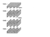
- the method of forming the fuel generating member 104 is a method of filling the mold with the material of the fuel generating member and compression molding, or, for example, mixing the material of the fuel generating member with a resin material or the like and pouring the material into the mold. A method in which the resin material is removed by heating evaporation or the like can be used. Also, as shown in FIG. 4, plate-like fuel generating members 104A and 104B each having a plurality of grooves 104m on the upper and lower surfaces may be formed by the above method and then joined together.
- the insulating layer 106 is formed between the fuel generation member 104 and the fuel electrode 102 and insulates the fuel generation member 104 and the fuel electrode 102. Since the electric resistance of the fuel generation member 104 changes depending on the fuel supply status, the output fluctuates when the fuel generation member 104 and the fuel electrode 102 are even partially connected. Therefore, by providing a porous insulating layer 106 that is permeable to fuel between the fuel generating member 104 and the fuel electrode 102, the influence on the output due to the change in the electric resistance of the fuel generating member 104 is prevented. .
- the material of the insulating layer 106 As the material of the insulating layer 106, as in the case of the electrolyte membrane 101, stabilized yttria zirconium (YSZ), LSGM (La—Sr—Ga—Mn) which is a perovskite compound, silicon dioxide, or the like can be used. .
- a method for forming the insulating layer 106 a vapor deposition method or a sputtering method may be used, or a complex method such as a dipping method, a chemical vapor deposition method (CVD method: Chemical-Vapor-Deposition), or an ALD method may be used. It is preferable because the film can be formed with a uniform film thickness even for various shapes.
- the insulating layer 106 may be a porous layer using the same material as the electrolyte membrane 101.
- the porous structure can be formed by changing the film forming conditions. In this case, since the insulating layer 106 is originally formed of the same material as that used for the electrolyte membrane 101, it is possible to eliminate restrictions such as a usable temperature due to different materials.
- the discharge surface of the fuel generating member 104 that discharges the fuel and the supply surface of the fuel electrode 102 to which the fuel is supplied are disposed to face each other, and are disposed in parallel at regular intervals with the insulating layer 106 interposed therebetween.
- the fuel generation member 104 When the overall temperature of the fuel generation member 104 is uniformly increased by the heater 110, the fuel is discharged in a planar shape from the discharge surface of the fuel generation member 104. In this way, the fuel generating member 104 can discharge the fuel from the entire discharge surface toward the entire supply surface of the fuel electrode 102.
- the fuel generation speed of the fuel generation member 104 is set to be substantially constant regardless of the position on the discharge surface. Specifically, thermochemical equilibrium is used. When the temperature of the fuel generating member 104 is raised or lowered, fuel corresponding to the deviation from the equilibrium state can be generated. Therefore, by making the temperature of the entire fuel generating member 104 uniform by using the heater 110, the temperature may vary depending on the location. Therefore, fuel can be generated at a constant speed.
- the fuel generation speed of the fuel generation member 104 can be obtained by keeping the fuel concentration of the insulating layer 106 between the fuel electrode 102 and the fuel generation member 104 constant when the battery is started. Can be made constant. This is because the electric power generated from the electrode is constant if the fuel concentration at the time of battery activation is constant regardless of the location. That is, the amount of fuel consumption is constant regardless of the location. In this case, the chemical equilibrium is shifted due to the consumed fuel, and fuel corresponding to the shift amount is newly generated from the fuel generating member 104. Since the fuel consumption is constant regardless of location, the fuel generation speed from the fuel generation member 104 is also constant regardless of location.
- a method of making the fuel concentration constant at the time of starting the battery regardless of the location is such that, for example, when the fuel is a gas or liquid, the fuel is sealed in the insulating layer 106 between the fuel electrode 102 and the fuel generating member 104 in advance. Just keep it. When the fuel is gas or liquid, diffusion occurs naturally and the concentration in the enclosed insulating layer 106 becomes constant, so that the fuel concentration can be made constant regardless of the location.
- the fuel generation member 104 that generates fuel is provided in the fuel cell 1, and the discharge surface of the fuel generation member 104 that discharges the fuel and the fuel in the fuel electrode 102 are disposed.
- the supply surfaces to be supplied are opposed to each other and arranged in parallel at regular intervals with the insulating layer 106 in between.
- the discharge surface of the fuel generation member 104 is planar from substantially the entire surface toward the supply surface of the fuel electrode 102. It is set as the structure discharge
- the fuel generation speed of the fuel generation member 104 is set to be substantially constant regardless of the position on the discharge surface, it is possible to further suppress a decrease in output due to variations in electromotive force, thereby further improving fuel efficiency. Can be increased.
- the porous insulating layer 106 that is permeable to the fuel is provided between the fuel generating member 104 and the fuel electrode 102, the electrical resistance of the fuel generating member 104 changes depending on the fuel generation state. In this case, a stable output can be obtained without being affected by the above.
- the cross-sectional shape of the hole 104h of the fuel generating member 104 is rectangular.
- the present invention is not limited to this, and may be circular, for example. In this case as well, the same effect as in the above-described embodiment can be obtained.
- the hole 104h is formed in the fuel generating member 104, and the insulating layer 106, the fuel electrode 102, the electrolyte membrane 101, and the oxidant electrode 103 are disposed inside the hole 104h.
- the insulating layer 106, the fuel electrode 102, the electrolyte membrane 101, and the oxidant electrode 103 may be stacked on the plate-shaped fuel generating member 104.
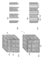
- Example 1 of the fuel cell 1 according to the embodiment of the present invention will be described with reference to FIGS. 2 and 3 are schematic views showing the manufacturing process of the fuel cell 1.
- FIGS. 2 (a1) to 2 (c1), 3 (a1), and 3 (b1) are external views in the respective processes.
- 2 (a2) to FIG. 2 (c2), FIG. 3 (a2), and FIG. 3 (b2) are schematic views showing the BB ′ section in FIG. 2 (a1) and FIG. 3 (a1), respectively. It is.
- the fuel cell 1 shown in FIG. 1 has the heater 110 built-in, a method for manufacturing the fuel cell 1 without the heater 110 will be described in Example 1 below.
- the heater 110 may be built in the process of forming the fuel generating member 104.
- the fuel generating member 104 having a plurality of holes 104h having a rectangular cross section was formed by filling a metal mold with iron powder and compression molding (FIG. 2 (a1), FIG. 2 (a2)).
- an LSGM film was formed using the ALD method along the inner surface of the hole 104h of the fuel generating member 104 to form an insulating layer 106 (FIG. 2 (b1), FIG. 2 (b2)).
- a Ni—Fe cermet was formed along the inner surface of the insulating layer 106 using the ALD method to form the fuel electrode 102 (FIG. 2 (c1), FIG. 2 (c2)). Subsequently, a lead wire 112 was connected to each formed fuel electrode 102.
- LSGM was formed along the inner surface of the fuel electrode 102 using the ALD method to form the electrolyte membrane 101 (FIG. 3 (a1), FIG. 3 (a2)).
- a La—Mn—O-based material was formed along the inner surface of the electrolyte membrane 101 using the ALD method to form the oxidizer electrode 103 (FIG. 3 (b1), FIG. 3 (b2)).
- the oxidant flow path 107 was formed by the inner wall surface of the formed oxidant electrode 103.
- the lead wire 112 was connected to each formed oxidant electrode 103 to complete the fuel cell 1.
- Example 2 of the fuel cell 1 according to the embodiment of the present invention will be described with reference to FIGS. 2, 3, and 4.
- FIG. 4 is a schematic diagram showing another method for forming the fuel generating member 104.
- Example 2 is also a method for manufacturing the fuel cell 1 in which the heater 110 is not incorporated.
- Mg is mixed into the resin, the mold is filled, and then heated to evaporate and dry the resin, so that the plate-like fuel generating members 104A and 104B having a plurality of grooves 104m on the upper and lower surfaces respectively. Formed (FIG. 4).
- the formed fuel generating members 104A and 104B were stacked and joined to form the fuel generating member 104 having a plurality of holes 104h having a rectangular cross section (FIGS. 2 (a1) and 2 (a2)).
- a silicon dioxide (SiO 2 ) film was formed along the inner surface of the hole 104h of the fuel generating member 104 by using a CVD method to form an insulating layer 106 (FIG. 2 (b1), FIG. 2 (b2)).
- a Ni-YSZ cermet was formed along the inner surface of the insulating layer 106 by using the ALD method to form the fuel electrode 102 (FIG. 2 (c1), FIG. 2 (c2)). Subsequently, a lead wire 112 was connected to each formed fuel electrode 102.
- a YSZ film was formed along the inner surface of the fuel electrode 102 using a dipping method to form an electrolyte film 101 (FIGS. 3 (a1) and 3 (a2)).
- a La—Mn—Ce-based material was formed along the inner surface of the electrolyte membrane 101 using a dipping method to form an oxidizer electrode 103 (FIG. 3 (b1), FIG. 3 (b2)).
- the oxidant flow path 107 was formed by the inner wall surface of the formed oxidant electrode 103.
- a lead wire 112 was connected to each formed oxidant electrode 103 to complete the fuel cell 1.
Abstract
Disclosed is a fuel cell which comprises an electrolyte membrane held between a fuel electrode and an oxidant electrode, and generates electric power by supplying a fuel and an oxidant gas respectively to the fuel electrode and the oxidant electrode. The fuel cell is characterized by comprising a fuel generating member, which is arranged so as to face the fuel electrode and planarly discharges the fuel from the surface thereof toward the fuel electrode, and an insulating layer, which is arranged between the fuel generating member and the fuel electrode and has permeability to the fuel. Consequently, the fuel cell can be small-sized and obtained at low cost, while having stably high fuel efficiency.
Description
本発明は、燃料電池に関し、特に燃料発生部材を有する燃料電池装置に関する。
The present invention relates to a fuel cell, and more particularly to a fuel cell device having a fuel generating member.
近年、水素と空気中の酸素から電力を取り出す燃料電池の開発が盛んに行われている。燃料電池は、発電時の排出物が水のみである為、環境に優れた発電方式であるだけでなく、原理的に取り出せる電力エネルギーの効率が高い為、省エネルギーになり、さらに、発電時に発生する熱を回収することにより、熱エネルギーをも利用することができるといった特徴を有しており、地球規模でのエネルギーや環境問題解決の切り札として期待されている。
In recent years, development of fuel cells that extract electric power from hydrogen and oxygen in the air has been actively conducted. Fuel cells are not only environmentally friendly power generation because the only waste generated during power generation is energy, but also the energy efficiency that can be extracted in principle is high, which saves energy and is generated during power generation. It has the feature that heat energy can be used by recovering heat, and it is expected as a trump card for solving global energy and environmental problems.
このような燃料電池は、例えば、固体ポリマーイオン交換膜を用いた固体高分子電解質膜、またはイットリア安定化ジルコニア(YSZ)を用いた固体酸化物電解質膜等を燃料極と酸化剤極とで両側から挟みこんだものを1つのセル構成としている。そして、セルには、燃料極に燃料ガスである水素を供給する水素流路、及び酸化剤極に酸化剤ガス例えば空気を供給する空気流路が設けられ、これらの流路を介して水素、空気をそれぞれ燃料極、酸化剤極に供給することで電気化学反応によって発電するものである(例えば、特許文献1参照)。
Such a fuel cell includes, for example, a solid polymer electrolyte membrane using a solid polymer ion exchange membrane or a solid oxide electrolyte membrane using yttria-stabilized zirconia (YSZ) on both sides of a fuel electrode and an oxidizer electrode. One cell structure is sandwiched between the two. The cell is provided with a hydrogen flow path for supplying hydrogen, which is a fuel gas, to the fuel electrode, and an air flow path for supplying an oxidant gas, for example, air, to the oxidant electrode, and hydrogen, Electric power is generated by an electrochemical reaction by supplying air to the fuel electrode and the oxidant electrode, respectively (see, for example, Patent Document 1).
しかしながら、特許文献1のような構成においては、水素流路が燃料極の表面に沿って形成され、水素流路に供給された水素は、該水素流路を進行するにつれて燃料極で消費される為、水素流路の上流と下流とで水素濃度が異なることとなる。この為、燃料極で発生する起電力は、該燃料極の場所により異なり、燃料極全体として取り出せる起電力は、燃料極内の起電力の低い部分の影響を受け低下する。すなわち、燃料電池の出力が低下し燃料効率が低下するという問題がある。
However, in the configuration as in Patent Document 1, the hydrogen flow path is formed along the surface of the fuel electrode, and the hydrogen supplied to the hydrogen flow path is consumed at the fuel electrode as it travels through the hydrogen flow path. Therefore, the hydrogen concentration is different between upstream and downstream of the hydrogen flow path. For this reason, the electromotive force generated at the fuel electrode differs depending on the location of the fuel electrode, and the electromotive force that can be taken out as a whole fuel electrode is affected by the low electromotive force in the fuel electrode and is reduced. That is, there is a problem that the output of the fuel cell is lowered and the fuel efficiency is lowered.
また、特許文献2は、ニッケルフェルトを備えた水素流路に水素ガスを供給するとともに、電池反応に使用されていない未反応水素ガスをリサイクルして燃料極に供給することを開示している。しかしながら、この特許文献2に開示の技術においても、水素ガスは水素流路に沿って供給されているため、燃料電池の出力の効率化には結びつかない。
Patent Document 2 discloses that hydrogen gas is supplied to a hydrogen flow path provided with nickel felt, and unreacted hydrogen gas that is not used in the battery reaction is recycled and supplied to the fuel electrode. However, even in the technique disclosed in Patent Document 2, since hydrogen gas is supplied along the hydrogen flow path, the efficiency of the output of the fuel cell is not linked.
さらに、特許文献3は、固体高分子型燃料電池の空気極から発生した水蒸気を燃料極側に配置された水素生成機構に供給し、この水素生成機構から発生された水素を燃料極に供給する燃料電池システムを開示している。しかしながら、このシステムにおいても、水蒸気が一方向に供給されているので、水素生成機構による水素の発生が水蒸気の上流側と下流側とで異なることになる。従って、特許文献3の構成においても、燃料電池の出力の効率化は困難である。
Further, Patent Document 3 supplies water vapor generated from the air electrode of a polymer electrolyte fuel cell to a hydrogen generation mechanism disposed on the fuel electrode side, and supplies hydrogen generated from the hydrogen generation mechanism to the fuel electrode. A fuel cell system is disclosed. However, in this system as well, since the water vapor is supplied in one direction, the generation of hydrogen by the hydrogen generation mechanism differs between the upstream side and the downstream side of the water vapor. Therefore, even in the configuration of Patent Document 3, it is difficult to improve the output efficiency of the fuel cell.
一方、特許文献4は、固体酸化物燃料電池と、水と反応して水素ガスを発生する水素含有燃料とを有する燃料電池システムを開示している。このシステムにおいては、燃料極側で発生した水を利用して水素含有燃料から水素ガスを発生させており、この水素ガスは導管又は開口を通じて燃料電池の燃料極に供給される。
On the other hand, Patent Document 4 discloses a fuel cell system having a solid oxide fuel cell and a hydrogen-containing fuel that reacts with water to generate hydrogen gas. In this system, hydrogen gas is generated from hydrogen-containing fuel using water generated on the fuel electrode side, and this hydrogen gas is supplied to the fuel electrode of the fuel cell through a conduit or an opening.
しかしながら、特許文献4は、燃料電池の出力の効率化を図るために、水素含有燃料と燃料極とを具体的にどのように配置するかについては何ら開示していない。
However, Patent Document 4 does not disclose any specific arrangement of the hydrogen-containing fuel and the fuel electrode in order to increase the output efficiency of the fuel cell.
本発明は、上記課題を鑑みてなされたもので、簡単な構成で、燃料効率が安定して高い燃料電池を提供することを目的とする。
The present invention has been made in view of the above problems, and an object of the present invention is to provide a fuel cell having a simple structure and a stable fuel efficiency.
上記目的は以下に記載の発明によって達成される。
The above object is achieved by the invention described below.
1.燃料極と酸化剤極との間に電解質膜が狭持された燃料電池であって、
燃料を前記燃料極に向けて面状に放出する燃料発生部材と、
前記燃料発生部材と前記燃料極との間に配置され、前記燃料に対し透過性を有する絶縁層と、を有することを特徴とする燃料電池。 1. A fuel cell in which an electrolyte membrane is sandwiched between a fuel electrode and an oxidant electrode,
A fuel generating member that discharges fuel in a plane toward the fuel electrode;
A fuel cell comprising: an insulating layer disposed between the fuel generating member and the fuel electrode and having permeability to the fuel.
本発明によれば、簡単な構成で、燃料極の全面に渡り均一な濃度の燃料を供給することができるので、燃料極で発生する起電力は、該燃料極の場所により異なることなく一定となる。その結果、起電力のばらつきによる出力の低下を抑え、燃料効率を高めることができる。
According to the present invention, the fuel having a uniform concentration can be supplied over the entire surface of the fuel electrode with a simple configuration. Therefore, the electromotive force generated at the fuel electrode is constant without depending on the location of the fuel electrode. Become. As a result, a decrease in output due to variations in electromotive force can be suppressed, and fuel efficiency can be increased.
さらに、燃料発生部材と燃料極との間に、燃料に対し透過性を有する絶縁層を設ける構成とした場合には、燃料発生部材の電気抵抗が燃料発生状況により変化しても、その影響を受けることなく安定した出力を得ることができる。
Further, when an insulating layer that is permeable to the fuel is provided between the fuel generating member and the fuel electrode, even if the electric resistance of the fuel generating member varies depending on the fuel generation state, the effect is not affected. Stable output can be obtained without receiving.
以下、図面に基づいて、本発明の実施形態に係る燃料電池を説明する。尚、本発明は、該実施の形態に限られない。
Hereinafter, a fuel cell according to an embodiment of the present invention will be described with reference to the drawings. The present invention is not limited to the embodiment.
先ず、本発明の実施形態に係る燃料電池の構成を、図1を用いて説明する。図1(a)は、燃料電池1の外観を示す模式図、図1(b)は、図1(a)におけるA-A′断面模式図、図1(c)は、図1(a)におけるB-B′断面模式図である。
First, the configuration of a fuel cell according to an embodiment of the present invention will be described with reference to FIG. 1A is a schematic diagram showing the appearance of the fuel cell 1, FIG. 1B is a schematic cross-sectional view taken along the line AA ′ in FIG. 1A, and FIG. 1C is FIG. 1A. FIG. 6 is a schematic cross-sectional view taken along the line BB ′ in FIG.
燃料電池1は、図1に示すように、電解質膜101、燃料極102、酸化剤極103、絶縁層106、燃料発生部材104、及びヒータ110等から構成される。
As shown in FIG. 1, the fuel cell 1 includes an electrolyte membrane 101, a fuel electrode 102, an oxidant electrode 103, an insulating layer 106, a fuel generating member 104, a heater 110, and the like.
燃料極102に燃料を供給する燃料発生部材104には、断面が矩形の複数の孔104hが形成され、孔104hの内面に沿って、絶縁層106、燃料極102、電解質膜101、酸化剤極103がこの順で積層され、孔104hの中央部には、酸化剤極103に酸化剤ガスOxを供給する酸化剤流路107が形成されている。また、燃料発生部材104の周囲には、燃料発生部材104の全体の温度を均一化する為のヒータ110が格子状に配置されている。尚、ヒータ110の配置は、格子状に限定されることなく、燃料発生部材104を均一に加熱できる配置であればよい。例えば、ヒータ110は燃料電池1とは別体にして、燃料電池1に近接して配置するようにしてもよい。
A plurality of holes 104h having a rectangular cross section are formed in the fuel generating member 104 that supplies fuel to the fuel electrode 102. The insulating layer 106, the fuel electrode 102, the electrolyte membrane 101, and the oxidant electrode are formed along the inner surface of the hole 104h. 103 are stacked in this order, and an oxidant channel 107 for supplying the oxidant gas Ox to the oxidant electrode 103 is formed in the center of the hole 104h. Around the fuel generation member 104, heaters 110 are arranged in a grid pattern to make the temperature of the fuel generation member 104 uniform. The arrangement of the heater 110 is not limited to a lattice shape, and may be any arrangement that can uniformly heat the fuel generating member 104. For example, the heater 110 may be separated from the fuel cell 1 and disposed close to the fuel cell 1.
本実施形態において、燃料とは水素であり、酸化剤ガスOxとは酸素を含有するガス、例えば空気である。
In this embodiment, the fuel is hydrogen, and the oxidant gas Ox is a gas containing oxygen, such as air.
燃料電池1は、燃料発生部材104から燃料極102に水素を供給し、酸化剤流路107から酸化剤極103に酸素を供給することで生じる電気化学反応によって発電する。本実施形態の燃料電池1としては、固体酸化物燃料電池(SOFC)を用いる。
The fuel cell 1 generates power by an electrochemical reaction that occurs when hydrogen is supplied from the fuel generating member 104 to the fuel electrode 102 and oxygen is supplied from the oxidant flow path 107 to the oxidant electrode 103. As the fuel cell 1 of the present embodiment, a solid oxide fuel cell (SOFC) is used.
電解質膜101の材料としては、発電時に燃料極102側に水を発生するものが好適であり、例えば安定化イットリアジルコニウム(YSZ)やペロブスカイト化合物であるLSGM(La-Sr-Ga-Mn)を用いた固体酸化物電解質を用いることができる。なお、電解質膜101の材料としては、これらに限定されることなく、酸素イオンを通すもの、また、水酸化物イオンを通すものであり、燃料電池の電解質としての特性を満たすものであればよい。この場合、発電時に燃料極102側に水が発生するので、発生した水を用いた化学反応によって燃料発生部材104から燃料(水素)を発生させることができる。
The material of the electrolyte membrane 101 is preferably a material that generates water on the fuel electrode 102 side during power generation. For example, stabilized yttria zirconium (YSZ) or LSGM (La—Sr—Ga—Mn) that is a perovskite compound is used. The solid oxide electrolyte can be used. The material of the electrolyte membrane 101 is not limited to these, and any material that allows oxygen ions to pass through or hydroxide ions to pass through and satisfies the characteristics as an electrolyte of a fuel cell. . In this case, since water is generated on the fuel electrode 102 side during power generation, fuel (hydrogen) can be generated from the fuel generating member 104 by a chemical reaction using the generated water.
電解質膜101の成膜方法としては電気化学蒸着法(CVD-EVD法:Chemical Vapor Deposition-Electrochemical Vapor Deposition)、原子層積層法(ALD法:Atomic Layer Deposition)、ディッピング法、塗布法等を用いることができる。
As a method for forming the electrolyte film 101, an electrochemical vapor deposition method (CVD-EVD method: Chemical Vapor Deposition-Electrochemical Deposition), an atomic layer deposition method (ALD method: Atomic Layer Deposition), a dipping method, a coating method, or the like. Can do.
燃料極102の材料としては、Ni-Feサーメット、Ni-YSZサーメット等を用いることができる。燃料極102の成膜方法は、ALD法等を用いることができる。
As the material of the fuel electrode 102, Ni-Fe cermet, Ni-YSZ cermet or the like can be used. As a method for forming the fuel electrode 102, an ALD method or the like can be used.
酸化剤極103の材料としては、La-Mn-O系材料、La-Co-Ce系材料等を用いることができる。酸化剤極103の成膜方法は、ALD法、ディッピング法等を用いることができる。
As a material of the oxidizer electrode 103, a La—Mn—O-based material, a La—Co—Ce-based material, or the like can be used. As a method for forming the oxidant electrode 103, an ALD method, a dipping method, or the like can be used.
燃料発生部材104の材料としては、化学反応によって燃料を発生するFeやMg合金、また、分子の構造によって燃料を脱吸着できるカーボンナノチューブ等を用いることができる。また、燃料発生部材104は、燃料を発生させるだけでなく、燃料を吸蔵(吸着)できるものでもよい。この場合、燃料発生部材104から燃料を発生させた後、吸蔵(吸着)作業を行うことで、繰り返し燃料発生部材104を用いることができる。燃料である水素を吸蔵できる材料としては、Ni、Fe、Pd、V、Mg等を基材料とする水素吸蔵合金を用いることができる。本実施形態においては、化学反応によって好適に水素を発生させることができる鉄(Fe)を用いる。
As the material of the fuel generating member 104, Fe or Mg alloy that generates fuel by a chemical reaction, carbon nanotubes that can desorb the fuel by a molecular structure, and the like can be used. Further, the fuel generating member 104 may not only generate fuel but also be able to occlude (adsorb) fuel. In this case, the fuel generating member 104 can be repeatedly used by performing the occlusion (adsorption) operation after generating the fuel from the fuel generating member 104. As a material capable of storing hydrogen as a fuel, a hydrogen storage alloy based on Ni, Fe, Pd, V, Mg, or the like can be used. In this embodiment, iron (Fe) that can suitably generate hydrogen by a chemical reaction is used.
燃料発生部材104の形成方法は、燃料発生部材の材料を金型に充填して、圧縮成型する方法、また、例えば樹脂材料等に燃料発生部材の材料を混合し、金型に流し込んだ後、樹脂材料を加熱蒸発等によって除去して成型する方法等を用いることができる。また、図4に示すように、上下の面にそれぞれ複数の溝104mを有する板状の燃料発生部材104A、104Bを上記の方法で成型した後、それぞれを接合することで形成してもよい。
The method of forming the fuel generating member 104 is a method of filling the mold with the material of the fuel generating member and compression molding, or, for example, mixing the material of the fuel generating member with a resin material or the like and pouring the material into the mold. A method in which the resin material is removed by heating evaporation or the like can be used. Also, as shown in FIG. 4, plate-like fuel generating members 104A and 104B each having a plurality of grooves 104m on the upper and lower surfaces may be formed by the above method and then joined together.
絶縁層106は、燃料発生部材104と燃料極102の間に形成され、燃料発生部材104と燃料極102とを絶縁する。燃料発生部材104は、その燃料供給状況によって電気抵抗が変化する為、燃料発生部材104と燃料極102が一部でも導通していると、出力が変動する。この為、燃料発生部材104と燃料極102の間に燃料に対して透過性を有する多孔質の絶縁層106を設けることで、燃料発生部材104の電気抵抗の変化による出力への影響を防止する。
The insulating layer 106 is formed between the fuel generation member 104 and the fuel electrode 102 and insulates the fuel generation member 104 and the fuel electrode 102. Since the electric resistance of the fuel generation member 104 changes depending on the fuel supply status, the output fluctuates when the fuel generation member 104 and the fuel electrode 102 are even partially connected. Therefore, by providing a porous insulating layer 106 that is permeable to fuel between the fuel generating member 104 and the fuel electrode 102, the influence on the output due to the change in the electric resistance of the fuel generating member 104 is prevented. .
絶縁層106の材料としては、電解質膜101の場合と同様に、安定化イットリアジルコニウム(YSZ)やペロブスカイト化合物であるLSGM(La-Sr-Ga-Mn)、また、二酸化ケイ素等を用いることができる。絶縁層106の成膜方法は、蒸着法やスパッタ法を用いてもよいし、ディッピング法や化学気相成長法(CVD法:Chemical-Vapor-Deposition)、ALD法等の方法を用いると、複雑な形状に対しても均一な膜厚で成膜ができるので好適である。
As the material of the insulating layer 106, as in the case of the electrolyte membrane 101, stabilized yttria zirconium (YSZ), LSGM (La—Sr—Ga—Mn) which is a perovskite compound, silicon dioxide, or the like can be used. . As a method for forming the insulating layer 106, a vapor deposition method or a sputtering method may be used, or a complex method such as a dipping method, a chemical vapor deposition method (CVD method: Chemical-Vapor-Deposition), or an ALD method may be used. It is preferable because the film can be formed with a uniform film thickness even for various shapes.
尚、絶縁層106は、電解質膜101の材料と同じ材料を用いて多孔質の層を形成してもよい。多孔質化は成膜条件を変えることで形成できる。この場合、もともと電解質膜101に用いる材料と同じ材料で絶縁層106を形成する為、材料が異なることによる使用可能温度等の制約を排除することができる。
The insulating layer 106 may be a porous layer using the same material as the electrolyte membrane 101. The porous structure can be formed by changing the film forming conditions. In this case, since the insulating layer 106 is originally formed of the same material as that used for the electrolyte membrane 101, it is possible to eliminate restrictions such as a usable temperature due to different materials.
燃料発生部材104の燃料を放出する放出面と、燃料極102の燃料が供給される供給面とは、互いに対向して配置され、絶縁層106を挟んで一定の間隔で平行に配置される。
The discharge surface of the fuel generating member 104 that discharges the fuel and the supply surface of the fuel electrode 102 to which the fuel is supplied are disposed to face each other, and are disposed in parallel at regular intervals with the insulating layer 106 interposed therebetween.
ヒータ110により、燃料発生部材104の全体の温度を一様に上昇させると、燃料が燃料発生部材104の放出面から面状に放出される。このようにして、燃料発生部材104は、その放出面の全面から燃料極102の供給面の全面に向けて燃料を放出することができる。
When the overall temperature of the fuel generation member 104 is uniformly increased by the heater 110, the fuel is discharged in a planar shape from the discharge surface of the fuel generation member 104. In this way, the fuel generating member 104 can discharge the fuel from the entire discharge surface toward the entire supply surface of the fuel electrode 102.
燃料発生部材104として鉄(Fe)を用いた場合には、下記式(1)に示す化学反応によって、Feは燃料極102で発生した水(H2O)との反応により酸化鉄(Fe3O4)に変化することで、水素(H2)を発生する。ここに、
4H2O+3Fe→4H2+Fe3O4・・・(1)
また、燃料発生部材104の燃料発生速度は、放出面上の位置によらず、略一定になるようにする。具体的には熱化学平衡を用いる。燃料発生部材104の温度を昇降させると、平衡状態からのずれに応じた燃料を発生させることができるので、燃料発生部材104全体の温度をヒータ110を用いて均一にすることで、場所によらず一定の速度で燃料を発生させることができる。 When iron (Fe) is used as thefuel generating member 104, Fe is reacted with water (H 2 O) generated at the fuel electrode 102 by a chemical reaction shown in the following formula (1), so that iron oxide (Fe 3 By changing to O 4 ), hydrogen (H 2 ) is generated. here,
4H 2 O + 3Fe → 4H 2 + Fe 3 O 4 (1)
Further, the fuel generation speed of thefuel generation member 104 is set to be substantially constant regardless of the position on the discharge surface. Specifically, thermochemical equilibrium is used. When the temperature of the fuel generating member 104 is raised or lowered, fuel corresponding to the deviation from the equilibrium state can be generated. Therefore, by making the temperature of the entire fuel generating member 104 uniform by using the heater 110, the temperature may vary depending on the location. Therefore, fuel can be generated at a constant speed.
4H2O+3Fe→4H2+Fe3O4・・・(1)
また、燃料発生部材104の燃料発生速度は、放出面上の位置によらず、略一定になるようにする。具体的には熱化学平衡を用いる。燃料発生部材104の温度を昇降させると、平衡状態からのずれに応じた燃料を発生させることができるので、燃料発生部材104全体の温度をヒータ110を用いて均一にすることで、場所によらず一定の速度で燃料を発生させることができる。 When iron (Fe) is used as the
4H 2 O + 3Fe → 4H 2 + Fe 3 O 4 (1)
Further, the fuel generation speed of the
また、化学平衡を用いると、燃料極102と燃料発生部材104との間の絶縁層106の電池起動時の燃料濃度を場所によらず一定にしておくことでも、燃料発生部材104の燃料発生速度を一定にすることができる。これは、電池起動時の燃料濃度が場所によらず一定であれば、電極から発生する電力が一定となる。つまり、燃料の消費量も場所によらず一定となる。この場合、消費された燃料によって化学平衡がずれ、そのずれ量に応じた燃料が新たに、燃料発生部材104から発生する。燃料の消費量が場所によらず一定なので、燃料発生部材104からの燃料発生速度も場所によらず一定になる。
Further, when chemical equilibrium is used, the fuel generation speed of the fuel generation member 104 can be obtained by keeping the fuel concentration of the insulating layer 106 between the fuel electrode 102 and the fuel generation member 104 constant when the battery is started. Can be made constant. This is because the electric power generated from the electrode is constant if the fuel concentration at the time of battery activation is constant regardless of the location. That is, the amount of fuel consumption is constant regardless of the location. In this case, the chemical equilibrium is shifted due to the consumed fuel, and fuel corresponding to the shift amount is newly generated from the fuel generating member 104. Since the fuel consumption is constant regardless of location, the fuel generation speed from the fuel generation member 104 is also constant regardless of location.
尚、電池起動時の燃料濃度を場所によらず一定にする方法は、例えば燃料が気体や液体の場合、予め燃料極102と燃料発生部材104との間の絶縁層106に燃料を封入しておけばよい。燃料が気体や液体の場合、自然に拡散が起こり、封入した絶縁層106内での濃度が一定になる為、燃料濃度を場所によらず一定にすることができる。
Note that a method of making the fuel concentration constant at the time of starting the battery regardless of the location is such that, for example, when the fuel is a gas or liquid, the fuel is sealed in the insulating layer 106 between the fuel electrode 102 and the fuel generating member 104 in advance. Just keep it. When the fuel is gas or liquid, diffusion occurs naturally and the concentration in the enclosed insulating layer 106 becomes constant, so that the fuel concentration can be made constant regardless of the location.
このように本発明の実施形態に係る燃料電池1においては、燃料を発生する燃料発生部材104を燃料電池1に設け、該燃料発生部材104の燃料を放出する放出面と燃料極102の燃料が供給される供給面を対向させ、絶縁層106を挟んで一定の間隔で平行に配置し、燃料発生部材104の放出面は、その略全面から燃料を燃料極102の供給面に向けて面状に放出する構成としている。これにより、燃料極102の供給面全面に渡り均一な濃度の燃料を供給することができるので、燃料極102で発生する起電力は、該燃料極102の場所により異なることなく一定となる。その結果、起電力のばらつきによる出力の低下を抑え、燃料効率を高めることができる。
As described above, in the fuel cell 1 according to the embodiment of the present invention, the fuel generation member 104 that generates fuel is provided in the fuel cell 1, and the discharge surface of the fuel generation member 104 that discharges the fuel and the fuel in the fuel electrode 102 are disposed. The supply surfaces to be supplied are opposed to each other and arranged in parallel at regular intervals with the insulating layer 106 in between. The discharge surface of the fuel generation member 104 is planar from substantially the entire surface toward the supply surface of the fuel electrode 102. It is set as the structure discharge | released. As a result, since fuel with a uniform concentration can be supplied over the entire supply surface of the fuel electrode 102, the electromotive force generated at the fuel electrode 102 is constant without depending on the location of the fuel electrode 102. As a result, a decrease in output due to variations in electromotive force can be suppressed, and fuel efficiency can be increased.
また、燃料発生部材104の燃料発生速度は、放出面上の位置によらず、略一定になるようにしているので、起電力のばらつきによる出力の低下をさらに抑えることができ、燃料効率をより高めることができる。
In addition, since the fuel generation speed of the fuel generation member 104 is set to be substantially constant regardless of the position on the discharge surface, it is possible to further suppress a decrease in output due to variations in electromotive force, thereby further improving fuel efficiency. Can be increased.
さらに、燃料発生部材104と燃料極102との間に、燃料に対し透過性を有する多孔質の絶縁層106を設ける構成としたので、燃料発生部材104の電気抵抗が燃料発生状況により変化した場合においても、その影響を受けることなく安定した出力を得ることができる。
Further, since the porous insulating layer 106 that is permeable to the fuel is provided between the fuel generating member 104 and the fuel electrode 102, the electrical resistance of the fuel generating member 104 changes depending on the fuel generation state. In this case, a stable output can be obtained without being affected by the above.
尚、本実施形態においては、燃料発生部材104の孔104hの断面形状を矩形としたが、これに限定されることなく、例えば、円形としてもよい。この場合も、前述の実施形態の場合と同様の効果を得ることができる。
In the present embodiment, the cross-sectional shape of the hole 104h of the fuel generating member 104 is rectangular. However, the present invention is not limited to this, and may be circular, for example. In this case as well, the same effect as in the above-described embodiment can be obtained.
また、本実施形態においては、燃料発生部材104に孔104hを形成し、その孔104hの内部に絶縁層106、燃料極102、電解質膜101および酸化剤極103を配置するものとしたが、これに限らず、例えば板状の燃料発生部材104の上に絶縁層106、燃料極102、電解質膜101および酸化剤極103を積層するようにしてもよい。
In the present embodiment, the hole 104h is formed in the fuel generating member 104, and the insulating layer 106, the fuel electrode 102, the electrolyte membrane 101, and the oxidant electrode 103 are disposed inside the hole 104h. For example, the insulating layer 106, the fuel electrode 102, the electrolyte membrane 101, and the oxidant electrode 103 may be stacked on the plate-shaped fuel generating member 104.
(実施例1)
本発明の実施形態に係る燃料電池1の実施例1を図2、図3を用いて説明する。図2、図3は、燃料電池1の製造工程を示す模式図であり、図2(a1)~図2(c1)、図3(a1)、図3(b1)は、各工程での外観を示す模式図、図2(a2)~図2(c2)、図3(a2)、図3(b2)は、それぞれ図2(a1)、図3(a1)におけるB-B′断面模式図である。 Example 1
Example 1 of the fuel cell 1 according to the embodiment of the present invention will be described with reference to FIGS. 2 and 3 are schematic views showing the manufacturing process of the fuel cell 1. FIGS. 2 (a1) to 2 (c1), 3 (a1), and 3 (b1) are external views in the respective processes. 2 (a2) to FIG. 2 (c2), FIG. 3 (a2), and FIG. 3 (b2) are schematic views showing the BB ′ section in FIG. 2 (a1) and FIG. 3 (a1), respectively. It is.
なお、図1で示す燃料電池1はヒータ110を内蔵したものであったが、以下の実施例1においては、ヒータ110を内蔵しない形態の燃料電池1の製造方法を説明する。ヒータ110を燃料電池1に内蔵する場合においては、燃料発生部材104を形成する工程において、ヒータ110を内蔵させればよい。
Although the fuel cell 1 shown in FIG. 1 has the heater 110 built-in, a method for manufacturing the fuel cell 1 without the heater 110 will be described in Example 1 below. When the heater 110 is built in the fuel cell 1, the heater 110 may be built in the process of forming the fuel generating member 104.
最初に、鉄粉を金型に充填し、圧縮成形することで、断面が矩形の複数の孔104hを有する燃料発生部材104を形成した(図2(a1)、図2(a2))。
First, the fuel generating member 104 having a plurality of holes 104h having a rectangular cross section was formed by filling a metal mold with iron powder and compression molding (FIG. 2 (a1), FIG. 2 (a2)).
次に、燃料発生部材104の孔104hの内面に沿って、ALD法を用いてLSGMを成膜し、絶縁層106を形成した(図2(b1)、図2(b2))。
Next, an LSGM film was formed using the ALD method along the inner surface of the hole 104h of the fuel generating member 104 to form an insulating layer 106 (FIG. 2 (b1), FIG. 2 (b2)).
次に、絶縁層106の内面に沿って、ALD法を用いてNi-Feサーメットを成膜し、燃料極102を形成した(図2(c1)、図2(c2))。続いて、形成された各燃料極102にリード線112を接続した。
Next, a Ni—Fe cermet was formed along the inner surface of the insulating layer 106 using the ALD method to form the fuel electrode 102 (FIG. 2 (c1), FIG. 2 (c2)). Subsequently, a lead wire 112 was connected to each formed fuel electrode 102.
次に、燃料極102の内面に沿って、ALD法を用いてLSGMを成膜し、電解質膜101を形成した(図3(a1)、図3(a2))。
Next, LSGM was formed along the inner surface of the fuel electrode 102 using the ALD method to form the electrolyte membrane 101 (FIG. 3 (a1), FIG. 3 (a2)).
次に、電解質膜101の内面に沿って、ALD法を用いてLa-Mn-O系材料を成膜し、酸化剤極103を形成した(図3(b1)、図3(b2))。このとき、形成された酸化剤極103の内面の壁面により酸化剤流路107が形成された。続いて、形成された各酸化剤極103にリード線112を接続し、燃料電池1を完成させた。
Next, a La—Mn—O-based material was formed along the inner surface of the electrolyte membrane 101 using the ALD method to form the oxidizer electrode 103 (FIG. 3 (b1), FIG. 3 (b2)). At this time, the oxidant flow path 107 was formed by the inner wall surface of the formed oxidant electrode 103. Subsequently, the lead wire 112 was connected to each formed oxidant electrode 103 to complete the fuel cell 1.
(実施例2)
次に、本発明の実施形態に係る燃料電池1の実施例2を、図2、図3及び図4を用いて説明する。図4は、燃料発生部材104の別の形成方法を示す模式図である。なお、実施例2も、ヒータ110を内蔵しない形態の燃料電池1の製造方法である。 (Example 2)
Next, Example 2 of the fuel cell 1 according to the embodiment of the present invention will be described with reference to FIGS. 2, 3, and 4. FIG. 4 is a schematic diagram showing another method for forming thefuel generating member 104. Example 2 is also a method for manufacturing the fuel cell 1 in which the heater 110 is not incorporated.
次に、本発明の実施形態に係る燃料電池1の実施例2を、図2、図3及び図4を用いて説明する。図4は、燃料発生部材104の別の形成方法を示す模式図である。なお、実施例2も、ヒータ110を内蔵しない形態の燃料電池1の製造方法である。 (Example 2)
Next, Example 2 of the fuel cell 1 according to the embodiment of the present invention will be described with reference to FIGS. 2, 3, and 4. FIG. 4 is a schematic diagram showing another method for forming the
最初に、樹脂にMgを混合し、金型に充填した後、加熱することで、樹脂を蒸発乾燥させて、上下の面にそれぞれ複数の溝104mを有する板状の燃料発生部材104A、104Bを形成した(図4)。
First, Mg is mixed into the resin, the mold is filled, and then heated to evaporate and dry the resin, so that the plate-like fuel generating members 104A and 104B having a plurality of grooves 104m on the upper and lower surfaces respectively. Formed (FIG. 4).
次に、形成された燃料発生部材104A、104Bを積層して接合し、断面が矩形の複数の孔104hを有する燃料発生部材104を形成した(図2(a1)、図2(a2))。
Next, the formed fuel generating members 104A and 104B were stacked and joined to form the fuel generating member 104 having a plurality of holes 104h having a rectangular cross section (FIGS. 2 (a1) and 2 (a2)).
次に、燃料発生部材104の孔104hの内面に沿って、CVD法を用いて二酸化ケイ素(SiO2)を成膜し、絶縁層106を形成した(図2(b1)、図2(b2))。
Next, a silicon dioxide (SiO 2 ) film was formed along the inner surface of the hole 104h of the fuel generating member 104 by using a CVD method to form an insulating layer 106 (FIG. 2 (b1), FIG. 2 (b2)). ).
次に、絶縁層106の内面に沿って、ALD法を用いてNi-YSZサーメットを成膜し、燃料極102を形成した(図2(c1)、図2(c2))。続いて、形成された各燃料極102にリード線112を接続した。
Next, a Ni-YSZ cermet was formed along the inner surface of the insulating layer 106 by using the ALD method to form the fuel electrode 102 (FIG. 2 (c1), FIG. 2 (c2)). Subsequently, a lead wire 112 was connected to each formed fuel electrode 102.
次に、燃料極102の内面に沿って、ディッピング法を用いてYSZを成膜し、電解質膜101を形成した(図3(a1)、図3(a2))。
Next, a YSZ film was formed along the inner surface of the fuel electrode 102 using a dipping method to form an electrolyte film 101 (FIGS. 3 (a1) and 3 (a2)).
次に、電解質膜101の内面に沿って、ディッピング法を用いてLa-Mn-Ce系材料を成膜し、酸化剤極103を形成した(図3(b1)、図3(b2))。このとき、形成された酸化剤極103の内面の壁面により酸化剤流路107が形成された。続いて、形成された各酸化剤極103にリード線112を接続し、燃料電池1を完成させた。
Next, a La—Mn—Ce-based material was formed along the inner surface of the electrolyte membrane 101 using a dipping method to form an oxidizer electrode 103 (FIG. 3 (b1), FIG. 3 (b2)). At this time, the oxidant flow path 107 was formed by the inner wall surface of the formed oxidant electrode 103. Subsequently, a lead wire 112 was connected to each formed oxidant electrode 103 to complete the fuel cell 1.
このようにして完成させた実施例1、実施例2による燃料電池1の性能を評価した結果、何れも出力変動が少なく、安定して高い出力が得られることが確認できた。
As a result of evaluating the performance of the fuel cells 1 according to Example 1 and Example 2 completed in this manner, it was confirmed that both output fluctuations were small and a stable high output could be obtained.
1 燃料電池
101 電解質膜
102 燃料極
103 酸化剤極
104 燃料発生部材
106 絶縁層
107 酸化剤流路
110 ヒータ
112 リード線 DESCRIPTION OF SYMBOLS 1Fuel cell 101 Electrolyte membrane 102 Fuel electrode 103 Oxidant electrode 104 Fuel generating member 106 Insulating layer 107 Oxidant flow path 110 Heater 112 Lead wire
101 電解質膜
102 燃料極
103 酸化剤極
104 燃料発生部材
106 絶縁層
107 酸化剤流路
110 ヒータ
112 リード線 DESCRIPTION OF SYMBOLS 1
Claims (9)
- 燃料極と酸化剤極との間に電解質膜が狭持された燃料電池であって、
燃料を前記燃料極に向けて面状に放出する燃料発生部材と、
前記燃料発生部材と前記燃料極との間に配置され、前記燃料に対し透過性を有する絶縁層と、を有することを特徴とする燃料電池。 A fuel cell in which an electrolyte membrane is sandwiched between a fuel electrode and an oxidant electrode,
A fuel generating member that discharges fuel in a plane toward the fuel electrode;
A fuel cell comprising: an insulating layer disposed between the fuel generating member and the fuel electrode and having permeability to the fuel. - 前記電解質膜は、発電時に前記燃料極で水を発生する電解質で構成されており、
前記燃料発生部材は、前記燃料極で発生された水との化学反応によって燃料である水素を発生することを特徴とする請求項1に記載の燃料電池。 The electrolyte membrane is composed of an electrolyte that generates water at the fuel electrode during power generation,
The fuel cell according to claim 1, wherein the fuel generating member generates hydrogen as a fuel by a chemical reaction with water generated at the fuel electrode. - 前記絶縁層は、多孔質であることを特徴とする請求項1または2に記載の燃料電池。 3. The fuel cell according to claim 1, wherein the insulating layer is porous.
- 前記絶縁層の材料は、前記電解質膜の材料と同じ材料であることを特徴とする請求項1から3の何れか1項に記載の燃料電池。 The fuel cell according to any one of claims 1 to 3, wherein the material of the insulating layer is the same material as that of the electrolyte membrane.
- 前記絶縁層の材料は、二酸化ケイ素を含むことを特徴とする請求項1から3の何れか1項に記載の燃料電池。 The fuel cell according to any one of claims 1 to 3, wherein the material of the insulating layer includes silicon dioxide.
- 前記燃料発生部材の材料は、鉄を含むことを特徴とする請求項1から5の何れか1項に記載の燃料電池。 The fuel cell according to any one of claims 1 to 5, wherein the material of the fuel generating member includes iron.
- 前記燃料発生部材には、孔が形成され、
前記孔の内面に沿って、前記絶縁層、前記燃料極、前記電解質膜、前記酸化剤極がこの順で積層され、前記孔の中央部には、前記酸化剤極に酸化剤ガスを供給する酸化剤流路が形成されていることを特徴とする請求項1から6の何れか1項に記載の燃料電池。 A hole is formed in the fuel generating member,
The insulating layer, the fuel electrode, the electrolyte membrane, and the oxidant electrode are laminated in this order along the inner surface of the hole, and an oxidant gas is supplied to the oxidant electrode at the center of the hole. The fuel cell according to any one of claims 1 to 6, wherein an oxidant flow path is formed. - 前記燃料発生部材には、前記孔が複数形成されていることを特徴とする請求項7に記載の燃料電池。 The fuel cell according to claim 7, wherein a plurality of the holes are formed in the fuel generating member.
- 前記燃料発生部材の温度を制御するためのヒータを有することを特徴とする請求項1から8の何れか1項に記載の燃料電池。 The fuel cell according to any one of claims 1 to 8, further comprising a heater for controlling a temperature of the fuel generating member.
Priority Applications (1)
| Application Number | Priority Date | Filing Date | Title |
|---|---|---|---|
| JP2011529406A JP4888615B2 (en) | 2010-01-07 | 2010-12-22 | Fuel cell |
Applications Claiming Priority (2)
| Application Number | Priority Date | Filing Date | Title |
|---|---|---|---|
| JP2010-001843 | 2010-01-07 | ||
| JP2010001843 | 2010-01-07 |
Publications (1)
| Publication Number | Publication Date |
|---|---|
| WO2011083691A1 true WO2011083691A1 (en) | 2011-07-14 |
Family
ID=44305428
Family Applications (1)
| Application Number | Title | Priority Date | Filing Date |
|---|---|---|---|
| PCT/JP2010/073146 WO2011083691A1 (en) | 2010-01-07 | 2010-12-22 | Fuel cell |
Country Status (2)
| Country | Link |
|---|---|
| JP (1) | JP4888615B2 (en) |
| WO (1) | WO2011083691A1 (en) |
Cited By (2)
| Publication number | Priority date | Publication date | Assignee | Title |
|---|---|---|---|---|
| JP2011222290A (en) * | 2010-04-09 | 2011-11-04 | Konica Minolta Holdings Inc | Fuel cell |
| WO2017009238A1 (en) * | 2015-07-16 | 2017-01-19 | Commissariat A L'energie Atomique Et Aux Energies Alternatives | Methods for (co)electrolysis of water (soec) or for producing electricity at a high temperature with exchangers incorporated as stages of a reactor stack (hte) or a fuel cell (sofc) |
Citations (3)
| Publication number | Priority date | Publication date | Assignee | Title |
|---|---|---|---|---|
| JP2006156198A (en) * | 2004-11-30 | 2006-06-15 | Kurita Water Ind Ltd | Supply device of fuel for fuel cell, supply method of fuel, and fuel cell system |
| JP2006232593A (en) * | 2005-02-23 | 2006-09-07 | Nitto Denko Corp | Hydrogen producing cell and hydrogen producing apparatus |
| JP2009099491A (en) * | 2007-10-19 | 2009-05-07 | Sharp Corp | Fuel cell system and electronic equipment |
-
2010
- 2010-12-22 JP JP2011529406A patent/JP4888615B2/en not_active Expired - Fee Related
- 2010-12-22 WO PCT/JP2010/073146 patent/WO2011083691A1/en active Application Filing
Patent Citations (3)
| Publication number | Priority date | Publication date | Assignee | Title |
|---|---|---|---|---|
| JP2006156198A (en) * | 2004-11-30 | 2006-06-15 | Kurita Water Ind Ltd | Supply device of fuel for fuel cell, supply method of fuel, and fuel cell system |
| JP2006232593A (en) * | 2005-02-23 | 2006-09-07 | Nitto Denko Corp | Hydrogen producing cell and hydrogen producing apparatus |
| JP2009099491A (en) * | 2007-10-19 | 2009-05-07 | Sharp Corp | Fuel cell system and electronic equipment |
Cited By (4)
| Publication number | Priority date | Publication date | Assignee | Title |
|---|---|---|---|---|
| JP2011222290A (en) * | 2010-04-09 | 2011-11-04 | Konica Minolta Holdings Inc | Fuel cell |
| WO2017009238A1 (en) * | 2015-07-16 | 2017-01-19 | Commissariat A L'energie Atomique Et Aux Energies Alternatives | Methods for (co)electrolysis of water (soec) or for producing electricity at a high temperature with exchangers incorporated as stages of a reactor stack (hte) or a fuel cell (sofc) |
| FR3038916A1 (en) * | 2015-07-16 | 2017-01-20 | Commissariat Energie Atomique | METHODS OF (CO) ELECTROLYSIS OF WATER (SOEC) OR PRODUCTION OF HIGH TEMPERATURE ELECTRICITY WITH INTEGRATED EXCHANGERS AS REACTOR STACK (EHT) OR FUEL CELL (SOFC) ) |
| US10597788B2 (en) | 2015-07-16 | 2020-03-24 | Commissariat A L'energie Atomique Et Aux Energies Alternatives | Methods for (co)electrolysis of water (SOEC) or for producing electricity at a high temperature with exchangers incorporated as stages of a reactor stack (HTE) or a fuel cell (SOFC) |
Also Published As
| Publication number | Publication date |
|---|---|
| JPWO2011083691A1 (en) | 2013-05-13 |
| JP4888615B2 (en) | 2012-02-29 |
Similar Documents
| Publication | Publication Date | Title |
|---|---|---|
| CN103843180B (en) | SOFC device | |
| US20120178012A1 (en) | Sealing member for solid oxide fuel cell and solid oxide fuel cell employing the same | |
| JP4816816B2 (en) | Fuel cell | |
| JP5551495B2 (en) | Fuel cell module | |
| JP4985600B2 (en) | Electronics | |
| CN104205461B (en) | Avoid the fuel shortage of anode tap fuel cell | |
| US20120058406A1 (en) | Solid oxide fuel cell | |
| ES2750033T3 (en) | Protection provision for solid oxide cell structure plates and procedure for forming such protection arrangement | |
| JP4888615B2 (en) | Fuel cell | |
| JP6353294B2 (en) | Gas diffusion sheet for fuel cell and fuel cell | |
| JP4896601B2 (en) | Operation control method of solid oxide fuel cell | |
| KR20110044657A (en) | Supported flat-tubular solid oxide fuel cell | |
| JP4888616B2 (en) | Fuel cell | |
| JP5092560B2 (en) | Polymer electrolyte fuel cell | |
| JP2004273141A (en) | Fuel cell system | |
| JP5515995B2 (en) | Fuel cell | |
| WO2017149561A1 (en) | Electrochemical device and hydrogen power storage system | |
| Pham et al. | A review of 2019 fuel cell technologies: modelling and controlling | |
| JP2005294152A (en) | Solid oxide fuel cell | |
| JP7057731B2 (en) | Fuel cell and fuel cell manufacturing method | |
| JP2011165371A (en) | Fuel cell | |
| Rey-Mermet | Microfabricated solid oxide fuel cells | |
| JP4643533B2 (en) | Fuel cell reformer with excellent thermal characteristics | |
| JP6034227B2 (en) | Solid oxide fuel cell system | |
| Yekani et al. | EFFECT OF GAS CHANNEL GEOMETRIES ON POLYMER EXCHANGE MEMBRANE FUEL CELL PERFORMANCE |
Legal Events
| Date | Code | Title | Description |
|---|---|---|---|
| WWE | Wipo information: entry into national phase |
Ref document number: 2011529406 Country of ref document: JP |
|
| 121 | Ep: the epo has been informed by wipo that ep was designated in this application |
Ref document number: 10842204 Country of ref document: EP Kind code of ref document: A1 |
|
| NENP | Non-entry into the national phase |
Ref country code: DE |
|
| 122 | Ep: pct application non-entry in european phase |
Ref document number: 10842204 Country of ref document: EP Kind code of ref document: A1 |