WO2011083561A1 - Information processing apparatus, information processing method, and program - Google Patents
Information processing apparatus, information processing method, and program Download PDFInfo
- Publication number
- WO2011083561A1 WO2011083561A1 PCT/JP2010/007606 JP2010007606W WO2011083561A1 WO 2011083561 A1 WO2011083561 A1 WO 2011083561A1 JP 2010007606 W JP2010007606 W JP 2010007606W WO 2011083561 A1 WO2011083561 A1 WO 2011083561A1
- Authority
- WO
- WIPO (PCT)
- Prior art keywords
- mode
- graphics
- switching
- graphics chip
- application
- Prior art date
Links
Images


Classifications
-
- G—PHYSICS
- G06—COMPUTING; CALCULATING OR COUNTING
- G06F—ELECTRIC DIGITAL DATA PROCESSING
- G06F8/00—Arrangements for software engineering
- G06F8/40—Transformation of program code
- G06F8/54—Link editing before load time
-
- G—PHYSICS
- G06—COMPUTING; CALCULATING OR COUNTING
- G06F—ELECTRIC DIGITAL DATA PROCESSING
- G06F1/00—Details not covered by groups G06F3/00 - G06F13/00 and G06F21/00
- G06F1/26—Power supply means, e.g. regulation thereof
- G06F1/32—Means for saving power
- G06F1/3203—Power management, i.e. event-based initiation of a power-saving mode
- G06F1/3234—Power saving characterised by the action undertaken
- G06F1/325—Power saving in peripheral device
- G06F1/3265—Power saving in display device
-
- G—PHYSICS
- G06—COMPUTING; CALCULATING OR COUNTING
- G06F—ELECTRIC DIGITAL DATA PROCESSING
- G06F1/00—Details not covered by groups G06F3/00 - G06F13/00 and G06F21/00
- G06F1/26—Power supply means, e.g. regulation thereof
- G06F1/32—Means for saving power
-
- Y—GENERAL TAGGING OF NEW TECHNOLOGICAL DEVELOPMENTS; GENERAL TAGGING OF CROSS-SECTIONAL TECHNOLOGIES SPANNING OVER SEVERAL SECTIONS OF THE IPC; TECHNICAL SUBJECTS COVERED BY FORMER USPC CROSS-REFERENCE ART COLLECTIONS [XRACs] AND DIGESTS
- Y02—TECHNOLOGIES OR APPLICATIONS FOR MITIGATION OR ADAPTATION AGAINST CLIMATE CHANGE
- Y02D—CLIMATE CHANGE MITIGATION TECHNOLOGIES IN INFORMATION AND COMMUNICATION TECHNOLOGIES [ICT], I.E. INFORMATION AND COMMUNICATION TECHNOLOGIES AIMING AT THE REDUCTION OF THEIR OWN ENERGY USE
- Y02D10/00—Energy efficient computing, e.g. low power processors, power management or thermal management
Landscapes
- Engineering & Computer Science (AREA)
- Theoretical Computer Science (AREA)
- General Engineering & Computer Science (AREA)
- Physics & Mathematics (AREA)
- General Physics & Mathematics (AREA)
- Software Systems (AREA)
- Power Sources (AREA)
- User Interface Of Digital Computer (AREA)
- Image Processing (AREA)
- Image Generation (AREA)
- Stored Programmes (AREA)
- Controls And Circuits For Display Device (AREA)
Abstract
Description
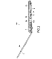
Fig. 1 is a perspective view showing a PC according to an embodiment of the present invention in the state of being opened. Fig. 2 is a left side view of the PC.
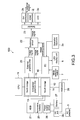
Fig. 3 is a block diagram showing the hardware structure of the
Next, the
Subsequently, a description will be given on mode switching operations in the PC structured as described above. In the following, the
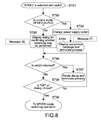
First, a description will be given on an operation of the
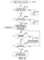
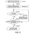
Subsequently, in the aforementioned modes, the operations of the
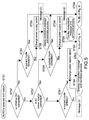
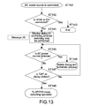
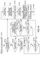
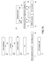
Next, the details of the switching operation to the STAMINA mode will be described. Fig. 14 is a flowchart showing the switching operation flow to the STAMINA mode. The operation of Fig. 14 includes an operation during the AUTO mode and an operation during the SPEED mode manually selected.
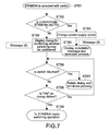
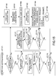
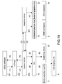
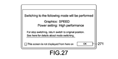
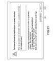
Fig. 15 is a flowchart showing the switching operation to the SPEED mode. The process shown in Fig. 15 is different, only in the mode, from the switching process to the STAMINA mode that is shown in Fig. 14. That is, the SPEED mode is involved in the process shown in Fig. 15, while the STAMINA mode is involved in the process shown in Fig. 14, so a description thereof will be omitted. Fig. 30 is a diagram showing an example of a message (message (11)) that urges the switching that is displayed during the AUTO mode in the switching process to the SPEED mode. As shown in Fig. 30, the message indicates that it may be impossible to use the
Next, a description will be given on the flow of a signal among blocks of the software and the hardware of the
As described above, according to this embodiment, the
The present invention is not limited to the above embodiment, and can be variously modified without departing from the gist of the present invention.
2j HDMI connector
2k DVI connector
3 display
3a LCD
5 AC adapter
7 mode selection switch
8 (8a, 8b, 8c) LED display
11 CPU
15 embedded graphics chip
16 EC
20 external graphics chip
21 HDD
22 switching circuit
26 power supply circuit
27 battery
28 DC jack
100 PC
201 utility software
204 graphics driver
221, 231, 251, 271 OK button
311 forced switching button
Claims (7)
- An information processing apparatus, comprising:
a first graphics chip to generate a first image signal, the first graphics chip having a first graphics performance;
a second graphics chip to generate a second image signal, the second graphics chip having a second graphics performance that is higher than the first graphics performance;
a switch to perform switching to cause one of the first graphics chip and the second graphics chip to operate;
a storage to store an application with a name of the application, the application being executed during an operation of the one of the first graphics chip and the second graphics chip;
a display to display one of the first image signal and the second image signal;
a connector connected with an external display to output the second image signal to the external display; and
a controller to control the switch to execute a first mode in which the first graphics chip is operated all the time, a second mode in which the second graphics chip is operated all the time, and a third mode in which switching between an operation of the first graphics chip and an operation of the second graphics chip is performed in accordance with whether the external display is connected to the connector, judge whether a trouble is caused in an operation of the application in execution due to the switching between the operations of the first and second graphics chips, and control the display to display the name of the application when judging that the trouble is caused. - The information processing apparatus according to claim 1,
wherein, in the third mode, the controller performs the switching between the operation of the first graphics chip and the operation of the second graphics chip in a case where the application is terminated after the name of the application is displayed. - The information processing apparatus according to claim 2, further comprising:
a power supply to supply power to the information processing apparatus from one of an AC adapter and a battery,
wherein, in the third mode, the controller
causes the first graphics chip to operate in a case where the external display is not connected to the connector, and the power is supplied from the battery, and
causes the second graphics chip to operate in a case where the external display is connected to the connector, and in a case where the external display is not connected to the connector and the power is supplied from the AC adapter. - The information processing apparatus according to claim 2, further comprising:
an operation input unit to receive an operation input by a user,
wherein, when judging that the trouble is caused during execution of the third mode, the controller displays, on the display, an operation dialog including a message that urges switching to one of the first mode and the second mode, displays the name of the application in a case where an operation for the switching is input from the operation input unit on the operation dialog, and performs the switching between the operation of the first graphics chip and the operation of the second graphics chip in a case where the application is terminated after the operation dialog is displayed and before the operation of the switching is input. - The information processing apparatus according to claim 3,
wherein the controller detects a first electric power value of electric power supplied from the power supply before the switching between the operation of the first graphics chip and the operation of the second graphics chip and a second electric power value of electric power supplied from the power supply after the switching, and displays information that indicates the first electric power value and the second electric power value on the display. - An information processing method for an information processing apparatus including a first graphics chip having a first graphics performance and a second graphics chip having a second graphics performance that is higher than the first graphics performance, comprising:
executing a first mode in which the first graphics chip is operated all the time, a second mode in which the second graphics chip is operated all the time, and a third mode in which switching between an operation of the first graphics chip and an operation of the second graphics chip is performed in accordance with whether an external display is connected to the information processing apparatus;
judging whether a trouble is caused in an operation of an application in execution due to the switching between the operations of the first and second graphics chips; and
displaying a name of the application when judging that the trouble is caused. - A program for causing an information processing apparatus including a first graphics chip having a first graphics performance and a second graphics chip having a second graphics performance that is higher than the first graphics performance to execute:
executing a first mode in which the first graphics chip is operated all the time, a second mode in which the second graphics chip is operated all the time, and a third mode in which switching between an operation of the first graphics chip and an operation of the second graphics chip is performed in accordance with whether an external display is connected to the information processing apparatus;
judging whether a trouble is caused in an operation of an application in execution due to the switching between the operations of the first and second graphics chips; and
displaying a name of the application when judging that the trouble is caused.
Priority Applications (5)
| Application Number | Priority Date | Filing Date | Title |
|---|---|---|---|
| RU2011153285/08A RU2011153285A (en) | 2010-01-07 | 2010-12-28 | INFORMATION PROCESSING DEVICE, INFORMATION PROCESSING METHOD AND PROGRAM |
| BRPI1015051A BRPI1015051A2 (en) | 2010-01-07 | 2010-12-28 | apparatus and method of processing information, and, program. |
| EP10842079A EP2454663A4 (en) | 2010-01-07 | 2010-12-28 | Information processing apparatus, information processing method, and program |
| CN201080029923.XA CN102473101B (en) | 2010-01-07 | 2010-12-28 | Information processing apparatus, information processing method, and program |
| US13/097,890 US8689019B2 (en) | 2010-01-07 | 2011-04-29 | Information processing apparatus, method, and program for switching between two graphics chips safely and easily in accordance with use purpose |
Applications Claiming Priority (2)
| Application Number | Priority Date | Filing Date | Title |
|---|---|---|---|
| JP2010001606A JP2011141707A (en) | 2010-01-07 | 2010-01-07 | Information processing apparatus, information processing method, and program |
| JP2010-001606 | 2010-01-07 |
Related Child Applications (1)
| Application Number | Title | Priority Date | Filing Date |
|---|---|---|---|
| US13/097,890 Continuation-In-Part US8689019B2 (en) | 2010-01-07 | 2011-04-29 | Information processing apparatus, method, and program for switching between two graphics chips safely and easily in accordance with use purpose |
Publications (1)
| Publication Number | Publication Date |
|---|---|
| WO2011083561A1 true WO2011083561A1 (en) | 2011-07-14 |
Family
ID=44305305
Family Applications (1)
| Application Number | Title | Priority Date | Filing Date |
|---|---|---|---|
| PCT/JP2010/007606 WO2011083561A1 (en) | 2010-01-07 | 2010-12-28 | Information processing apparatus, information processing method, and program |
Country Status (8)
| Country | Link |
|---|---|
| US (1) | US8689019B2 (en) |
| EP (1) | EP2454663A4 (en) |
| JP (1) | JP2011141707A (en) |
| KR (1) | KR20120111956A (en) |
| CN (1) | CN102473101B (en) |
| BR (1) | BRPI1015051A2 (en) |
| RU (1) | RU2011153285A (en) |
| WO (1) | WO2011083561A1 (en) |
Families Citing this family (3)
| Publication number | Priority date | Publication date | Assignee | Title |
|---|---|---|---|---|
| DE112012006459T5 (en) * | 2012-06-05 | 2015-02-26 | Mitsubishi Electric Corporation | display device |
| KR101952831B1 (en) | 2012-12-03 | 2019-02-28 | 삼성전자주식회사 | Electronic apparatus, external apparatus and method for controlling the same |
| CN112860428A (en) * | 2019-11-28 | 2021-05-28 | 华为技术有限公司 | High-energy-efficiency display processing method and equipment |
Citations (4)
| Publication number | Priority date | Publication date | Assignee | Title |
|---|---|---|---|---|
| JP2007048219A (en) * | 2005-08-12 | 2007-02-22 | Fujitsu Ltd | Power consumption management system |
| JP2009151242A (en) * | 2007-12-21 | 2009-07-09 | Toshiba Corp | Information processing device and display control method |
| JP2009539192A (en) * | 2006-05-30 | 2009-11-12 | エーティーアイ・テクノロジーズ・ユーエルシー | Device having a plurality of graphics subsystems and reduced power consumption mode, software and method of operating the device |
| JP2010020596A (en) * | 2008-07-11 | 2010-01-28 | Sony Corp | Information processor, information processing method and program thereof |
Family Cites Families (18)
| Publication number | Priority date | Publication date | Assignee | Title |
|---|---|---|---|---|
| CA2193764A1 (en) * | 1995-12-25 | 1997-06-25 | Yasuyuki Mochizuki | Selective call receiver |
| JP2776359B2 (en) * | 1996-01-26 | 1998-07-16 | 日本電気株式会社 | State changeover switch that can be switched by one operation |
| US6806893B1 (en) * | 1997-08-04 | 2004-10-19 | Parasoft Corporation | System and method for displaying simulated three dimensional buttons in a graphical user interface |
| US6724389B1 (en) * | 2001-03-30 | 2004-04-20 | Intel Corporation | Multiplexing digital video out on an accelerated graphics port interface |
| WO2002086745A2 (en) * | 2001-04-23 | 2002-10-31 | Quantum 3D, Inc. | System and method for synchronization of video display outputs from multiple pc graphics subsystems |
| US6832269B2 (en) * | 2002-01-04 | 2004-12-14 | Silicon Integrated Systems Corp. | Apparatus and method for supporting multiple graphics adapters in a computer system |
| US7256795B2 (en) * | 2002-07-31 | 2007-08-14 | Ati Technologies Inc. | Extended power management via frame modulation control |
| US20050044437A1 (en) * | 2003-08-19 | 2005-02-24 | Dunstan Robert A. | Power conservation in the absence of AC power |
| US7663633B1 (en) * | 2004-06-25 | 2010-02-16 | Nvidia Corporation | Multiple GPU graphics system for implementing cooperative graphics instruction execution |
| US20080143731A1 (en) | 2005-05-24 | 2008-06-19 | Jeffrey Cheng | Video rendering across a high speed peripheral interconnect bus |
| US7034487B1 (en) * | 2005-06-30 | 2006-04-25 | Overhead Door Corporation | Barrier operator controller with user settable control limits when entrapment device present |
| JP5076317B2 (en) * | 2005-12-27 | 2012-11-21 | ソニー株式会社 | Information processing apparatus, information processing method, and program thereof |
| US8384700B2 (en) | 2007-01-26 | 2013-02-26 | Microsoft Corporation | Linked shell |
| EP1855181A2 (en) * | 2006-05-10 | 2007-11-14 | Marvell World Trade Ltd. | System with high power and low power processors and thread transfer |
| CN101118460A (en) * | 2006-05-10 | 2008-02-06 | 马维尔国际贸易有限公司 | Adaptive storage system including hard disk drive with flash interface |
| US8555099B2 (en) | 2006-05-30 | 2013-10-08 | Ati Technologies Ulc | Device having multiple graphics subsystems and reduced power consumption mode, software and methods |
| CN101978352B (en) * | 2007-12-13 | 2017-11-03 | 先进微装置公司 | For with multiple graphics subsystem, the driver framework of the computing device of the power dissipation modes of reduction, software and method |
| JP5446844B2 (en) * | 2009-12-24 | 2014-03-19 | ソニー株式会社 | Information processing apparatus and switch apparatus |
-
2010
- 2010-01-07 JP JP2010001606A patent/JP2011141707A/en active Pending
- 2010-12-28 BR BRPI1015051A patent/BRPI1015051A2/en not_active IP Right Cessation
- 2010-12-28 RU RU2011153285/08A patent/RU2011153285A/en unknown
- 2010-12-28 EP EP10842079A patent/EP2454663A4/en not_active Withdrawn
- 2010-12-28 CN CN201080029923.XA patent/CN102473101B/en not_active Expired - Fee Related
- 2010-12-28 WO PCT/JP2010/007606 patent/WO2011083561A1/en active Application Filing
- 2010-12-28 KR KR1020117031546A patent/KR20120111956A/en not_active Application Discontinuation
-
2011
- 2011-04-29 US US13/097,890 patent/US8689019B2/en not_active Expired - Fee Related
Patent Citations (4)
| Publication number | Priority date | Publication date | Assignee | Title |
|---|---|---|---|---|
| JP2007048219A (en) * | 2005-08-12 | 2007-02-22 | Fujitsu Ltd | Power consumption management system |
| JP2009539192A (en) * | 2006-05-30 | 2009-11-12 | エーティーアイ・テクノロジーズ・ユーエルシー | Device having a plurality of graphics subsystems and reduced power consumption mode, software and method of operating the device |
| JP2009151242A (en) * | 2007-12-21 | 2009-07-09 | Toshiba Corp | Information processing device and display control method |
| JP2010020596A (en) * | 2008-07-11 | 2010-01-28 | Sony Corp | Information processor, information processing method and program thereof |
Non-Patent Citations (5)
| Title |
|---|
| "NEW SONY NOTEBOOKS DELIVER THE ULTIMATE IN MOBILITY PERFORMANCE AND ENTERTAINMENT", SONY ELECTRONICS, 6 January 2010 (2010-01-06), XP008150073, Retrieved from the Internet <URL:http://news.sel.sony.com/en/press_room/consumer/computer_peripheral/notebooks/release/55906.html> [retrieved on 20110131] * |
| "Unable to switch display card on IdeaPad V360/V460", LENOVO, 10 January 2011 (2011-01-10), Retrieved from the Internet <URL:http://consumersupport.lenovo.com/in/en/HintsandTips/hints_show_12947146012942.html> [retrieved on 20110131] * |
| NORIHIKO WAKASUGI: "Optimus Technology: 3rd generation GPU switching technology by NVIDIA", PC WATCH, IMPRESS WATCH CORPORATION, 9 February 2010 (2010-02-09), Retrieved from the Internet <URL:http://pc.watch.impress.co.jp/docs/news/20100209347871.html> [retrieved on 20110131] * |
| See also references of EP2454663A4 * |
| SONY ELECTRONICS INC., SONY ELECTRONICS NEWS & INFORMATION, 31 January 2011 (2011-01-31), XP008150075, Retrieved from the Internet <URL:http://news.sel.sony.com/en/press_room/consumer/computerperipheral/notebooks?page=3&archive=> * |
Also Published As
| Publication number | Publication date |
|---|---|
| KR20120111956A (en) | 2012-10-11 |
| US20110261062A1 (en) | 2011-10-27 |
| EP2454663A4 (en) | 2013-02-27 |
| JP2011141707A (en) | 2011-07-21 |
| CN102473101A (en) | 2012-05-23 |
| BRPI1015051A2 (en) | 2019-09-24 |
| EP2454663A1 (en) | 2012-05-23 |
| RU2011153285A (en) | 2013-07-10 |
| CN102473101B (en) | 2014-09-17 |
| US8689019B2 (en) | 2014-04-01 |
Similar Documents
| Publication | Publication Date | Title |
|---|---|---|
| CN106020990B (en) | Control method of central processing unit and terminal equipment | |
| EP2539805B1 (en) | Systems and methods for hot plug gpu power control | |
| US20140149931A1 (en) | Information processing apparatus and display control method | |
| KR101952831B1 (en) | Electronic apparatus, external apparatus and method for controlling the same | |
| US9110687B2 (en) | Information processing apparatus and operation control method | |
| JP4748188B2 (en) | Information processing apparatus, information processing method, and program thereof | |
| CN109346014B (en) | Virtual reality equipment and screen control method thereof | |
| CN101430592A (en) | Information processing apparatus | |
| JP6140006B2 (en) | Information processing apparatus and output control method | |
| JP5058361B1 (en) | Electronic device, display panel control device, and display panel control method | |
| US20140146085A1 (en) | Electronic Equipment, Program, And Control Method | |
| JP2015179330A (en) | Electrical apparatus and display method | |
| WO2011083561A1 (en) | Information processing apparatus, information processing method, and program | |
| JP4607545B2 (en) | Information processing apparatus and power control method | |
| CN101755452A (en) | Display apparatus | |
| EP1521236A2 (en) | Electronic display device and method of controlling such a display device | |
| JP5221694B2 (en) | Electronic device, object display method, and object display program. | |
| JP2007102444A (en) | Electronic equipment, method for controlling electronic equipment and control program | |
| JP2007317073A (en) | Information processor and control method | |
| US20150145767A1 (en) | Electronic device and display method | |
| KR101070625B1 (en) | Display apparatus | |
| US20160077786A1 (en) | Electronic device, method and storage medium | |
| US20230030973A1 (en) | Change of firmware settings | |
| TWI465914B (en) | Method for docking and undocking peripheral apparatus during transition of power management mode | |
| KR100873134B1 (en) | Monitor and display method of input signal using it |
Legal Events
| Date | Code | Title | Description |
|---|---|---|---|
| WWE | Wipo information: entry into national phase |
Ref document number: 201080029923.X Country of ref document: CN |
|
| 121 | Ep: the epo has been informed by wipo that ep was designated in this application |
Ref document number: 10842079 Country of ref document: EP Kind code of ref document: A1 |
|
| ENP | Entry into the national phase |
Ref document number: 2011153285 Country of ref document: RU Kind code of ref document: A |
|
| ENP | Entry into the national phase |
Ref document number: 20117031546 Country of ref document: KR Kind code of ref document: A |
|
| WWE | Wipo information: entry into national phase |
Ref document number: 2010842079 Country of ref document: EP |
|
| WWE | Wipo information: entry into national phase |
Ref document number: 33/CHENP/2012 Country of ref document: IN |
|
| NENP | Non-entry into the national phase |
Ref country code: DE |
|
| REG | Reference to national code |
Ref country code: BR Ref legal event code: B01A Ref document number: PI1015051 Country of ref document: BR |
|
| ENP | Entry into the national phase |
Ref document number: PI1015051 Country of ref document: BR Kind code of ref document: A2 Effective date: 20111227 |