WO2011077632A1 - 画像符号化装置、画像符号化方法および画像符号化プログラム、ならびに画像復号装置、画像復号方法および画像復号プログラム - Google Patents
画像符号化装置、画像符号化方法および画像符号化プログラム、ならびに画像復号装置、画像復号方法および画像復号プログラム Download PDFInfo
- Publication number
- WO2011077632A1 WO2011077632A1 PCT/JP2010/006715 JP2010006715W WO2011077632A1 WO 2011077632 A1 WO2011077632 A1 WO 2011077632A1 JP 2010006715 W JP2010006715 W JP 2010006715W WO 2011077632 A1 WO2011077632 A1 WO 2011077632A1
- Authority
- WO
- WIPO (PCT)
- Prior art keywords
- prediction
- image
- motion vector
- block
- motion
- Prior art date
- Legal status (The legal status is an assumption and is not a legal conclusion. Google has not performed a legal analysis and makes no representation as to the accuracy of the status listed.)
- Ceased
Links
Images




Classifications
-
- H—ELECTRICITY
- H04—ELECTRIC COMMUNICATION TECHNIQUE
- H04N—PICTORIAL COMMUNICATION, e.g. TELEVISION
- H04N19/00—Methods or arrangements for coding, decoding, compressing or decompressing digital video signals
- H04N19/50—Methods or arrangements for coding, decoding, compressing or decompressing digital video signals using predictive coding
- H04N19/503—Methods or arrangements for coding, decoding, compressing or decompressing digital video signals using predictive coding involving temporal prediction
- H04N19/51—Motion estimation or motion compensation
- H04N19/537—Motion estimation other than block-based
-
- H—ELECTRICITY
- H04—ELECTRIC COMMUNICATION TECHNIQUE
- H04N—PICTORIAL COMMUNICATION, e.g. TELEVISION
- H04N19/00—Methods or arrangements for coding, decoding, compressing or decompressing digital video signals
- H04N19/10—Methods or arrangements for coding, decoding, compressing or decompressing digital video signals using adaptive coding
- H04N19/102—Methods or arrangements for coding, decoding, compressing or decompressing digital video signals using adaptive coding characterised by the element, parameter or selection affected or controlled by the adaptive coding
- H04N19/103—Selection of coding mode or of prediction mode
- H04N19/105—Selection of the reference unit for prediction within a chosen coding or prediction mode, e.g. adaptive choice of position and number of pixels used for prediction
-
- H—ELECTRICITY
- H04—ELECTRIC COMMUNICATION TECHNIQUE
- H04N—PICTORIAL COMMUNICATION, e.g. TELEVISION
- H04N19/00—Methods or arrangements for coding, decoding, compressing or decompressing digital video signals
- H04N19/46—Embedding additional information in the video signal during the compression process
-
- H—ELECTRICITY
- H04—ELECTRIC COMMUNICATION TECHNIQUE
- H04N—PICTORIAL COMMUNICATION, e.g. TELEVISION
- H04N19/00—Methods or arrangements for coding, decoding, compressing or decompressing digital video signals
- H04N19/60—Methods or arrangements for coding, decoding, compressing or decompressing digital video signals using transform coding
- H04N19/61—Methods or arrangements for coding, decoding, compressing or decompressing digital video signals using transform coding in combination with predictive coding
Definitions
- the present invention relates to an image encoding device that encodes an image using motion compensated prediction, an image encoding method, an image encoding program, an image decoding device that decodes the encoded image, an image decoding method, and an image decoding. Regarding the program.
- MPEG series standard motion compensation that divides a frame into a plurality of blocks and predicts motion from other frames is used.
- H.264 a mechanism for switching and using an optimum one from a plurality of motion compensation block sizes is introduced.
- the present inventor further reduced the overall code amount by compressing the motion vector information in an image coding method that uses both motion compensation prediction by parallel movement and motion compensation prediction by geometric transformation. I found a method to compress.
- the present invention has been made in view of such a situation, and an object of the present invention is to improve the compression efficiency of a code amount in an image coding method using both motion compensation prediction by parallel movement and motion compensation prediction by geometric transformation. Is to provide.
- An image encoding apparatus is an image encoding apparatus that encodes a moving image, and includes a target block in a target image and a reference block in a reference image that is translated with the target block. Between the target block in the target image and the reference block in the reference image that is geometrically transformed with the target block.
- a geometric transformation motion compensation prediction unit that generates a motion vector and a prediction signal, a prediction method by a translation motion compensation prediction unit, and a prediction method by a geometric transformation motion compensation prediction unit for each target block in the target image. Calculates the difference between the prediction method determination unit for determining which one to adopt, the prediction signal generated by the prediction method employed by the prediction method determination unit, and the image signal of the target block.
- a prediction error signal generation unit that generates a prediction error signal, prediction method information for specifying a prediction method adopted by the prediction method determination unit, a motion vector related to the prediction method, and a prediction error signal generation unit
- An encoding unit that encodes the predicted error signal.
- the encoding unit predictively encodes the motion vector of the target block with reference to the motion vector of the adjacent block, the encoding unit performs parallel motion compensation prediction or performs geometric conversion motion compensation prediction.
- a motion vector to be referred to is determined regardless of whether it exists.
- the geometric transformation motion compensation prediction unit selects a plurality of representative pixels from the target block, detects a motion vector of each representative pixel, and calculates a motion vector of pixels other than the plurality of representative pixels of the target block.
- the calculation may be performed by at least one of interpolation and extrapolation using the motion vector of the representative pixel.
- the geometric transformation motion compensation prediction unit may select a pixel corresponding to the approximate center or approximate center of gravity of the small block when the target block is divided into small blocks as the representative pixel.
- the target block is a square region
- the geometric transformation motion compensation prediction unit detects a motion vector for each of the four representative pixels of the four square small blocks obtained by dividing the target block into four equal parts.
- a second mode in which a motion vector is detected for each of two representative pixels of two vertically long rectangular small blocks obtained by horizontally dividing the target block; and two horizontally long rectangular small blocks obtained by vertically dividing the target block
- a third mode in which a motion vector is detected for each of the two representative pixels, and the prediction method determination unit uses the first mode, the second mode, and the third mode as prediction methods by the geometric transformation motion compensation prediction unit. Either of these may be adopted.
- This image decoding apparatus decodes prediction method information, a motion vector, and a prediction error signal included in an encoded stream encoded by combining motion compensation prediction by parallel movement and motion compensated prediction by geometric transformation.
- translation motion A control unit that specifies whether to use a prediction method by the compensation prediction unit or a prediction method by the geometric transformation motion compensation prediction unit, a prediction signal generated by the prediction method specified by the control unit, and decoding by the decoding unit
- An image signal generation unit that generates an image signal from the
- the motion vector of the target block is predictively encoded with reference to the motion vector of the adjacent block regardless of whether the motion compensation prediction method of the adjacent block is translation motion compensation prediction or geometric conversion motion compensation prediction.
- the decoding unit decodes the motion vector of the target block subjected to predictive encoding with reference to the motion vector of the adjacent block regardless of the motion compensation prediction method of the adjacent block.
- a plurality of representative pixels are selected for the target block, and motion vectors of the representative pixels are predictively encoded and included in the encoded stream.
- the geometric transformation motion compensation prediction unit includes a plurality of representative pixels of the target block.
- the motion vectors of the other pixels may be calculated by at least one of interpolation and extrapolation using the decoded motion vectors of the plurality of representative pixels.
- the representative pixel may be selected as a pixel corresponding to the approximate center or approximate center of gravity of the small block when the target block is divided into small blocks.
- the target block is a square area
- the prediction method information for designating motion compensated prediction by the geometric transformation motion compensated prediction unit includes four representatives of four square small blocks obtained by dividing the target block into four equal parts.
- a first mode in which a motion vector is detected for each pixel a second mode in which a motion vector is detected for each of two representative pixels of two vertically long rectangular blocks obtained by dividing the target block into two equal parts, and a target Any of the third modes in which a motion vector is detected for each of two representative pixels of two horizontally-long rectangular small blocks obtained by dividing a block into two vertically may be specified.
- the compression efficiency of the code amount can be improved by an image coding method using both motion compensation prediction by parallel movement and motion compensation prediction by geometric transformation.
- FIGS. 2A to 2H are diagrams for explaining a macroblock partition and a sub-macroblock partition.
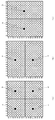
- FIGS. 3A to 3C are diagrams for explaining representative points of the first mode, the second mode, and the third mode of the geometric transformation.
- FIGS. 4A to 4D are diagrams for explaining motion vector predictive coding. It is a figure for demonstrating an example of the scaling process of a motion vector value. It is a flowchart which shows the encoding process procedure of a macroblock in the image coding apparatus which concerns on Embodiment 1 of this invention.
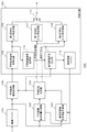
- FIG. 1 is a block diagram showing a configuration of an image encoding device 100 according to Embodiment 1 of the present invention.
- the image encoding device 100 includes an image buffer 101, a translational motion compensation prediction unit 102, a geometric transformation motion compensation prediction unit 103, a prediction method determination unit 104, a prediction error signal generation unit 105, and an encoding unit 150.
- the encoding unit 150 includes a prediction error signal encoding unit 106, a first encoded bit sequence generation unit 107, a second encoded bit sequence generation unit 108, a third encoded bit sequence generation unit 109, a prediction error signal decoding unit 110, and a decoded image.
- a signal generation unit 111, a decoded image buffer 112, and an output switch 113 are included.
- the image buffer 101 temporarily stores image signals to be encoded supplied in order of shooting / display time.
- the image buffer 101 converts the stored image signal to be encoded in predetermined pixel block units (here, macroblock units) into a translational motion compensation prediction unit 102, a geometric transformation motion compensation prediction unit 103, and a prediction error.
- the signal is supplied to the signal generator 105 in parallel. At this time, the images supplied in the order of shooting / display time are rearranged in the encoding order and output from the image buffer 101.
- a macro block refers to a luminance signal of 16 ⁇ 16 pixels and two corresponding color difference signal blocks.
- YUV of the color difference format is 4: 2: 0, the color difference signal has a size of 8 ⁇ 8 pixels.
- an intra coding method that encodes within a screen without using a reference image, a motion compensation prediction method by translation using a reference image, and a motion compensation prediction method by geometric transformation using a reference image Is used.
- the reference image is a decoded image obtained by local decoding.
- the configuration is omitted in FIG.
- These coding system modes are adaptively switched individually or in combination in units of macroblocks. Note that a method of encoding all macroblocks using a motion compensated prediction method based on geometric transformation using a reference image is also possible.
- the translational motion compensation prediction unit 102 generates a motion vector and a prediction signal between the target block in the target image and the reference block in the reference image that has a translational relationship with the target block.
- the translational motion compensation prediction unit 102 performs motion compensation prediction based on translation similar to the existing motion compensation prediction stipulated in the AVC / H.264 scheme or the like.
- a forward or backward decoded image is used as a reference image in a display order supplied from a decoded image buffer 112 described later.
- the translational motion compensation prediction unit 102 performs block matching between the macroblock signal supplied from the image buffer 101 and the reference image signal supplied from the decoded image buffer 112 within a predetermined detection range in the reference image. Do.
- the translational motion compensation prediction unit 102 specifies a reference block signal in the reference image signal having the smallest error from the macroblock signal by block matching, and a motion vector between the macroblock signal and the reference block signal Is detected.
- Each of the plurality of modes has a different reference index, motion compensation block size, L0 / L1 prediction, and the like.
- the reference index is an index indicating a reference picture. Note that L0 / L1 prediction can be selected only in the B slice. A specific example of the block size will be described later.
- motion compensation can be performed with a pixel accuracy of less than one pixel.
- motion compensation can be performed up to an accuracy of 1/4 of a luminance signal and 1/8 of an accuracy of a color difference signal.
- a signal with pixel accuracy of less than one pixel is generated from the surrounding signals by interpolation using a signal of an integer pixel in the reference image.
- the translational motion compensation prediction unit 102 performs motion compensation prediction in each mode, and sends a prediction signal (more specifically, a motion compensation prediction block signal) and a motion vector in each mode to the prediction method determination unit 104. Supply.
- FIG. 2 is a diagram for explaining a macroblock partition and a sub-macroblock partition.
- the macroblock is defined by a square area.
- AVC / H. In the MPEG series including the H.264 system, a block defined by 16 ⁇ 16 pixels (16 horizontal pixels and 16 vertical pixels) is called a macro block.
- AVC / H. In the H.264 system, a block defined by 8 ⁇ 8 pixels is called a sub macroblock.
- the macroblock partition refers to each small block obtained by further dividing the macroblock for motion compensation prediction.
- the sub-macroblock partition refers to each small block obtained by further dividing the sub-macroblock for motion compensation prediction.
- FIG. 2 (a) is a diagram showing that a macroblock is composed of one macroblock partition composed of a luminance signal of 16 ⁇ 16 pixels and two corresponding color difference signals.
- this configuration is referred to as a 16 ⁇ 16 mode macroblock type.
- the macroblock is composed of two macroblock partitions each composed of a luminance signal of 16 ⁇ 8 pixels (horizontal 16 pixels, vertical 8 pixels) and two corresponding color difference signals.
- FIG. 2B the macroblock is composed of two macroblock partitions each composed of a luminance signal of 16 ⁇ 8 pixels (horizontal 16 pixels, vertical 8 pixels) and two corresponding color difference signals.
- FIG. The two macroblock partitions are arranged vertically.
- this configuration is called a 16 ⁇ 8 mode macroblock type.
- the macroblock is composed of two macroblock partitions composed of a luminance signal of 8 ⁇ 16 pixels (horizontal 8 pixels, vertical 16 pixels) and two corresponding color difference signals.
- FIG. 2 (c) the macroblock is composed of two macroblock partitions composed of a luminance signal of 8 ⁇ 16 pixels (horizontal 8 pixels, vertical 16 pixels) and two corresponding color difference signals.
- FIG. The two macroblock partitions are arranged side by side.
- this configuration is referred to as an 8 ⁇ 16 mode macroblock type.
- FIG. 2D is a diagram showing that a macroblock is composed of four macroblock partitions each composed of a luminance signal of 8 ⁇ 8 pixels and two corresponding color difference signals. These four macroblock partitions are arranged vertically and horizontally. This configuration is referred to as an 8 ⁇ 8 mode macroblock type. Note that a macroblock partition including the luminance signal of 8 ⁇ 8 pixels and two corresponding color difference signals is referred to as a sub macroblock.
- FIG. 2 (e) is a diagram showing that the sub-macroblock is composed of one sub-macroblock partition composed of a luminance signal of 8 ⁇ 8 pixels and two corresponding color difference signals.
- this configuration is referred to as an 8 ⁇ 8 mode sub-macroblock type.
- the sub-macroblock is composed of two sub-macroblock partitions each composed of a luminance signal of 8 ⁇ 4 pixels (horizontal 8 pixels, vertical 4 pixels) and two corresponding color difference signals.
- FIG. 2F the sub-macroblock partitions are arranged vertically. This configuration is referred to as an 8 ⁇ 4 mode sub-macroblock type.
- the sub-macroblock is composed of two macroblock partitions each composed of a luminance signal of 4 ⁇ 8 pixels (horizontal 4 pixels, vertical 8 pixels) and two corresponding color difference signals.
- FIG. The two macroblock partitions are arranged side by side.
- this configuration is called a 4 ⁇ 8 mode sub-macroblock type.
- FIG. 2 (h) is a diagram showing that the sub-macroblock is composed of four sub-macroblock partitions each composed of a luminance signal of 4 ⁇ 4 pixels and two corresponding color difference signals. These four sub-macroblock partitions are arranged two by two vertically and horizontally. Here, this configuration is called a 4 ⁇ 4 mode sub-macroblock type.
- a mechanism for switching and using an optimum one from the above motion compensation block sizes is adopted.
- one of macroblock types of 16 ⁇ 16, 16 ⁇ 8, 8 ⁇ 16, and 8 ⁇ 8 modes is selected as the motion compensation block size for each macroblock.
- the motion compensation block size in units of submacroblocks is among the 8 ⁇ 8, 8 ⁇ 4, 4 ⁇ 8, and 4 ⁇ 4 mode sub macroblock types. Is selected.
- the luminance signal is motion compensated with the number of pixels of the selected size.
- the color difference format is 4: 2: 0, the color difference signal is motion-compensated with half the number of pixels both horizontally and vertically.
- motion compensation block size information is encoded with syntax elements called macroblock types and sub-macroblock types.
- the syntax is an expression rule of the encoded bit string, and the syntax element is information that is specified to be transmitted in the syntax.
- one motion vector is encoded / decoded for each macroblock partition in the case of L0 prediction and L1 prediction. That is, one motion vector for the 16 ⁇ 16 mode macroblock type, two motion vectors for the 16 ⁇ 8 and 8 ⁇ 16 mode macroblock types, and 4 for the 8 ⁇ 8 mode macroblock type. Each motion vector is encoded and decoded.
- Each pixel of the luminance signal and the color difference signal of each macroblock partition is motion compensated according to one motion vector of the macroblock partition. That is, each pixel is motion-compensated using the same motion vector.
- the geometric transformation motion compensation prediction unit 103 performs motion vector and prediction signal between the target block in the target image and the reference block in the reference image having a geometric transformation relationship with the target block. Is generated. More specifically, the geometric transformation motion compensation prediction unit 103 sets a representative pixel for each small block when the target block is virtually divided into a plurality of small blocks, and the motion vector of each representative pixel is set. Is detected. At that time, the geometric transformation motion compensation prediction unit 103 sets the pixel at the approximate center or approximate center of gravity of the small block as the representative pixel.
- the geometric transformation motion compensation prediction unit 103 calculates a motion vector of pixels other than the plurality of representative pixels of the target block using at least one of interpolation and extrapolation from the motion vectors of the plurality of representative pixels.
- the notation of interpolation / extrapolation is used to mean at least one of interpolation and extrapolation.
- the geometric transformation motion compensation prediction unit 103 encodes and decodes motion vectors of four representative pixels a, b, c, and d of the target block (see FIG. 3A described later), and the target block.
- the second mode for encoding and decoding the motion vectors of the two representative pixels e and f in the vertical direction see FIG.
- a third mode for encoding / decoding vectors can be executed.
- the first mode when the target block is virtually divided into four crosses and divided into four square small blocks, the center or approximately center of each of the four small blocks is set as a representative pixel
- the second mode Is a case where the target block is virtually divided into two vertically divided and divided into two horizontally-long rectangular small blocks, and the center or approximate center of each of the two small blocks is used as a representative pixel.
- the center or approximately center of each of the two small blocks when divided into two vertically long rectangular small blocks by dividing into two horizontally is set as a representative pixel.
- the target block is described as a macro block of 16 ⁇ 16 pixels, but the size of the target block is not limited to 16 ⁇ 16 pixels. It may be a sub-macroblock of 8 pixels, or a block of 32 ⁇ 32 pixels, 48 ⁇ 48 pixels, 64 ⁇ 64 pixels, or the like.
- the small block is described as a macroblock partition, the present invention is not limited to this, and the block may be a sub macroblock and the small block may be a sub macroblock partition.
- the prediction method determination unit 104 can employ any of the first mode, the second mode, and the third mode described above as the prediction method by the geometric transformation motion compensation prediction unit 103. Detailed processing of the prediction method determination unit 104 will be described later.
- the geometric transformation motion compensation prediction unit 103 is different from the existing motion compensation prediction based on the parallel movement defined in the AVC / H.264 method, etc., and in addition to the parallel movement, the geometric transformation accompanied by deformation including enlargement / reduction / rotation, etc. Perform motion compensation prediction by scientific conversion.
- each pixel of the luminance signal and chrominance signal of the macroblock, macroblock partition, sub-macroblock is not motion-compensated with the same motion vector, but for each pixel.
- Different motion vectors are created for motion compensation.
- the first mode of geometric transformation motion compensated prediction corresponds to the macroblock type of 8x8 mode
- the second mode corresponds to the macroblock type of 16x8
- the third mode corresponds to the macroblock type of 8x16 To do.
- the macroblock type is not defined by the shape of the pixel block, but by the number of motion vectors, representative pixel positions, and motion vector interpolation / extrapolation methods. Is done.
- the motion vector of the non-representative pixel is calculated by at least one of interpolation and extrapolation based on the motion vector of the representative pixel.
- the geometric transformation motion compensation prediction unit 103 selects a pixel at the center or near the center of each macroblock partition including the sub-macroblock as a representative pixel, and obtains a motion vector thereof.
- a macroblock partition since the number of vertical and horizontal pixels is an even number, there is no exact center pixel. Therefore, a specific one of the four pixels located at the center is set as a representative pixel, or the coordinates of the exact center pixel are obtained by interpolation to set a virtual pixel as the representative pixel.
- the geometric transformation motion compensated prediction unit 103 may use a motion vector calculated in units of pixels by an optical flow method or the like as a motion vector of a representative pixel of each macroblock partition, or a reliability such as an edge or corner of an image. You may correct
- the motion vector of the corresponding macroblock / partition generated by the translational motion compensation / prediction unit 102 may be used.
- the motion vector value is applied to the representative pixel, and the motion vector value is verified by adjusting the motion vector value in the increasing direction and decreasing direction. May be corrected.
- the geometric transformation motion compensation prediction unit 103 performs linear interpolation / extrapolation of the motion vector of the non-representative pixel in the macroblock from the motion vector of the representative pixel (in this embodiment, bilinear interpolation / extrapolation). Calculated by
- the geometric transformation motion compensation prediction unit 103 calculates the motion vectors of the two representative pixels e and f in the vertical direction from A motion vector of a pixel on a straight line connecting these two points is calculated by at least one of interpolation and extrapolation. Then, the motion vectors of the other pixels and the motion vectors of the respective pixels subjected to linear interpolation / extrapolation are applied as they are in the horizontal direction. It is assumed that an operation in which a motion vector is directly applied is included in the interpolation / extrapolation.
- the geometric transformation motion compensation prediction unit 103 calculates these two points from the motion vectors of the two representative pixels in the horizontal direction.
- the motion vector of the pixels on the straight line connecting the two is calculated by at least one of interpolation and extrapolation, and the motion vectors of the other pixels are used as they are in the vertical direction. Apply.
- the geometric transformation motion compensation prediction unit 103 performs interpolation and extrapolation both in the horizontal direction and in the vertical direction.
- the motion vector of the non-representative pixel is calculated by at least one of them. Interpolation and extrapolation may be performed at once in both the horizontal and vertical directions by the method described later, or the motion vectors of pixels on a straight line connecting these two points are interpolated from the motion vectors of two representative pixels in the horizontal direction.
- the value of the motion vector of the representative pixel e is set to the value of the motion vector of the representative pixels a and b.
- the value of the motion vector of the representative pixel f is set to the value of the motion vector of the representative pixels c and d.
- the value of the motion vector of the representative pixel g is set to the value of the motion vector of the representative pixels a and c.
- the value of the motion vector of the second representative pixel h is set to the value of the motion vector of the representative pixels b and d.
- the motion vectors of the non-representative pixels can be calculated.
- the geometric transformation motion compensation prediction unit 103 performs motion compensation for each pixel using the calculated motion vector for each pixel.
- the example of calculating the motion vector of each pixel included in the macroblock has been described.
- the motion vector of each pixel included in the sub-macroblock can be calculated in the same manner. By such processing, deformation including enlargement / reduction / rotation can be expressed, and processing equivalent to geometric transformation can be realized.
- This pixel-by-pixel motion vector calculation process and motion compensation process for each pixel are performed in a plurality of prescribed modes.
- Each of the plurality of modes has a different reference index, motion compensation block size, L0 / L1 prediction, and the like. Note that L0 / L1 prediction can be selected only in the B slice.
- the geometric transformation motion compensation prediction unit 103 performs motion compensation prediction in each mode, and predicts a prediction signal (more specifically, a motion compensation prediction block signal) and a motion vector in each mode. To supply.
- FIG. 3A illustrates a method of calculating the motion vector of each pixel of the macroblock type in the first mode that encodes and decodes the motion vectors of the four representative pixels a, b, c, and d of the target block. It is a figure for doing.
- the representative pixel is represented by a black circle
- the non-representative pixel is represented by a white circle
- the representative pixel is represented by a pixel a (3, 3), a pixel b (11, 3), which is near the center of each macroblock partition.
- Pixel c (3, 11) and pixel d (11, 11) are set.
- the coordinate of each pixel is represented by (i, j)
- the coordinate in the horizontal direction is represented by i in the unit of one pixel
- the coordinate in the vertical direction is represented by j in the unit of one pixel.
- the upper left pixel in the macroblock is the origin (0, 0)
- the right direction and the downward direction are positive.
- motion vectors of the pixel a, pixel b, pixel c, and pixel d are assigned, and then motion vectors of other pixels are calculated by linear interpolation / extrapolation.
- the motion vectors of the pixel a, pixel b, pixel c and pixel d are assigned.
- the motion vectors of the two representative pixels e and f are encoded and decoded, the motion vectors of the pixel e and the pixel f are assigned, and the motion vector of the pixel e is also the motion vector of the pixels a and b.
- the motion vector of the pixel f is also the motion vector of the pixels c and d.
- the motion vectors of the pixel g and the pixel h are assigned, and the motion vector of the pixel g is also the motion vector of the pixels a and c.
- the motion vector of pixel h is also the motion vector of pixels b and d.
- the motion vectors V (i, j) of the other pixels are calculated from the motion vectors Va, Vb, Vc, Vd of the four representative pixels a, b, c, d by linear interpolation / extrapolation.
- V (i, j) ⁇ (15 ⁇ i ⁇ 3) (15 ⁇ j ⁇ 3) Va + i (15 ⁇ j ⁇ 3) Vb + (15 ⁇ i ⁇ 3) (j ⁇ 3) ⁇ Vc + (i ⁇ 3) (J-3) Vd ⁇
- Expression (1) As described above, the motion vector for each pixel in the first mode, the second mode, and the third mode is calculated. It can also be calculated by the following method.
- V (i, 11) Vc + (Vd ⁇ Vc) * (i ⁇ 3) / 8 Equation (3)
- V (i, j) V (i, 3) + (V (i, 11) ⁇ V (i, 3)) * (j ⁇ 3) / 8 Expression (4)
- the motion vector of each pixel in the first mode, the second mode, and the third mode can be calculated.
- the second mode and the third mode it can also be calculated by the following method.
- FIG. 3B is a diagram for explaining a method of calculating the motion vector of each pixel of the macroblock type in the second mode that encodes and decodes the motion vectors of the two representative pixels e and f of the target block. It is.
- the representative pixels are set to the pixel e (7, 3) and the pixel f (7, 11) that are near the center of each macroblock partition.
- the motion vectors of these pixels e and f are assigned, and then the motion vectors of the other pixels are calculated by linear interpolation / extrapolation.
- V (i, j) Ve + (Vf ⁇ Ve) * (j ⁇ 3) / 8 Expression (7)
- FIG. 3C illustrates a method of calculating the motion vector of each pixel of the third mode macroblock type that encodes and decodes the motion vectors of the two representative pixels g and h in the horizontal direction of the target block.
- the representative pixels are set to the pixel g (3, 7) and the pixel h (11, 7) that are near the center of each macroblock partition.
- the motion vectors of these pixels g and h are assigned, and then the motion vectors of the other pixels are calculated by linear interpolation / extrapolation.
- V (i, j) Vg + (Vh ⁇ Vg) * (i ⁇ 3) / 8 Equation (10)
- the geometric conversion motion compensation prediction unit 103 performs motion compensation prediction on each pixel according to the calculated motion vector of each pixel. More specifically, motion compensation prediction is performed by generating an interpolation signal from the reference image pixel indicated by the motion vector of each pixel. It should be noted that the accuracy of the motion vector of each pixel, the rounding of numerical values required in the calculation process, and the like need to be defined so that the same value is obtained regardless of which decoding device is used. In addition, when the coordinate of the prediction pixel designated by the motion vector is expressed by a decimal point, the pixel is interpolated from surrounding pixels at the time of motion compensation. As the interpolation method, 4 to 6 tap filtering, linear interpolation, or the like can be used.
- the first mode that encodes and decodes the motion vectors of the four representative pixels a, b, c, and d, it cannot be expressed in the second mode or the third mode, such as enlargement / reduction, rotation, translation, etc., with the four motion vectors. Deformation can be represented.
- the two motion vectors can represent uniform deformation in the vertical direction in addition to translation.
- the expressive power of deformation is limited compared to the first mode, the number of motion vectors to be encoded can be reduced.
- the third mode in which the motion vectors of the two representative pixels g and h in the horizontal direction of the target block are encoded and decoded, the two motion vectors can represent uniform deformation in the horizontal direction in addition to translation.
- the expressive power of deformation is limited compared to the first mode, the number of motion vectors to be encoded can be reduced.
- the prediction method determination unit 104 employs either the prediction method by the translational motion compensation prediction unit 102 or the prediction method by the geometric transformation motion compensation prediction unit 103 for each target block in the target image. To decide. More specifically, it is determined which mode of which prediction method is adopted. Hereinafter, prediction method selection including mode selection is referred to.
- the prediction method determining unit 104 selects which reference image is used to encode motion compensation prediction based on parallel movement or motion compensated prediction based on geometric transformation in which pixel block unit. Decide how. In the case of motion compensation prediction by geometric transformation, one of the first mode, the second mode, and the third mode is selected. At that time, the prediction method is determined by determining which combination of these items is the prediction method capable of realizing the most efficient encoding.
- rate distortion theory considering the relationship between the code amount and distortion can be used.
- the code amount of the macroblock (that is, the prediction method information, the motion vector, and the total code amount of the prediction signal) is calculated, and the distortion amount is calculated from the difference between the encoding target image and the decoded image.
- a prediction method is selected that minimizes a code amount and a rate distortion function using the distortion amount as an input variable. Note that the prediction method is described in a macroblock type. In the case of translation motion compensation, it is described in the macroblock type as to which of the 16 ⁇ 16/16 ⁇ 8/8 ⁇ 16/8 ⁇ 8 mode is used, and in the case of geometric transformation motion compensation, the first mode, the first mode The macroblock type is described as to whether the second mode or the third mode is used.
- the first mode of geometric transformation motion compensated prediction is an 8 ⁇ 8 macroblock type that encodes four motion vectors
- the second mode is a 16 ⁇ 8 macroblock that encodes two motion vectors
- the third mode is described as an 8 ⁇ 16 macroblock type that also encodes two motion vectors.
- the prediction method determination unit 104 sends the prediction method information described in the adopted macroblock type and the motion vector generated by the prediction method to the first encoded bit sequence generation unit 107 and the second encoded bit sequence generation unit 108.
- the motion vector corresponding to the employed prediction method is supplied to the second encoded bit string generation unit 108.
- the prediction method determination unit 104 supplies the prediction signal generated by the employed prediction method to the prediction error signal generation unit 105.
- the prediction error signal generation unit 105 calculates a difference between the prediction signal generated by the prediction method adopted by the prediction method determination unit 104 and the image signal of the target block, and generates a prediction error signal. More specifically, the prediction error signal generation unit 105 subtracts the prediction signal supplied from the prediction method determination unit 104 from the image signal to be encoded supplied from the image buffer 101 to obtain a prediction error signal. Generated and supplied to the prediction error signal encoding unit 106.
- the encoding unit 150 includes prediction method information for specifying the prediction method adopted by the prediction method determination unit 104, a motion vector generated by the prediction method, and a prediction error signal generated by the prediction error signal generation unit 105. Is encoded.
- the second encoded bit string generation unit 108 of the encoding unit 150 performs predictive encoding with reference to the motion vector of the adjacent block. At that time, regardless of whether the motion compensation prediction method of the adjacent block is translation motion compensation prediction or geometric conversion motion compensation prediction, both are handled in common and the motion vector of the adjacent block to be referenced is determined. To do.
- the reference relationship between the motion vector of the target block and the motion vector of the adjacent block is the difference between the motion vector of the block that uses the parallel motion compensation prediction method and the motion vector that uses the geometric transformation motion compensation prediction. But it holds. That is, in the motion vector predictive coding, the relationship is a mixture of both.
- the motion vector of the representative pixel is the target of predictive encoding.
- a representative of the adjacent block refer to the motion vector of the pixel.
- the prediction error signal encoding unit 106 performs compression encoding processing such as orthogonal transform and quantization on the prediction error signal supplied from the prediction error signal generation unit 105 to generate an encoded prediction error signal.
- the third encoded bit string generator 109 and the prediction error signal decoder 110 are supplied.
- the first encoded bit string generation unit 107 encodes the prediction method information described by the macroblock type supplied from the prediction method determination unit 104 by entropy encoding such as arithmetic encoding, and generates an encoded bit string. .
- the prediction block size to be included in the prediction method information L0 / L1 prediction distinction, and the like are combined and encoded as a macroblock type.
- the following description method can be used as information for identifying which of motion compensation prediction by parallel movement and motion compensation prediction by geometric transformation to be included in the prediction method information.
- the macroblock type encoding method may be shared, and syntax elements for determining motion compensation prediction by parallel movement and motion compensation prediction by geometric transformation may be separately prepared and described.
- the macroblock type may be extended and described by combining with information to be encoded as the macroblock type.
- the second encoded bit string generation unit 108 encodes the motion vector supplied from the prediction method determination unit 104 to generate an encoded bit string.
- the motion vector is predictively encoded.
- the prediction vector is calculated by predicting the motion vector from the adjacent block using the correlation with the motion vector of the neighboring block already encoded or decoded. Note that the correlation with the motion vectors of neighboring neighboring blocks can be specified based on the prediction method information supplied from the prediction method determination unit 104.
- a difference vector that is a difference between the prediction vector and the motion vector of the target block or the target pixel is calculated, and the difference vector is encoded, thereby reducing the amount of coding of the motion vector.
- a motion vector of the representative pixel is a target for encoding.
- FIG. 4 is a diagram for explaining a motion vector prediction method.
- FIG. 4A shows an example of predicting a motion vector between macroblocks in which no partition is set.
- FIG. 4B shows an example in which motion vectors are predicted between macroblocks in which partitions are set.
- FIG. 4C shows an example in which a motion vector is predicted in a 16 ⁇ 8 pixel macroblock.
- FIG. 4D shows an example in which a motion vector is predicted in a macroblock of 8 ⁇ 16 pixels.
- FIGS. 4A to 4D AVC / H.
- a motion vector prediction method employed in the H.264 system will be described. In this motion vector prediction method, a motion vector of a target block is predicted using a median value of motion vectors of neighboring neighboring blocks.
- the motion vector of the block painted in gray is the encoding target.
- the motion vector of the target block is predicted using three motion vectors of the block A adjacent to the left of the target block, the block B adjacent to the upper right, and the block C adjacent to the upper right. More specifically, a median value is taken for each of the horizontal component and the vertical component from these three motion vectors to obtain a prediction vector.
- a motion vector for L0 prediction and a motion vector for L1 prediction are handled separately. Prediction for the L0 prediction of the target block by performing prediction using three motion vectors for the L0 prediction of the block A on the left of the target block, the block B on the upper right, and the block C on the upper right. Calculate the vector.
- the prediction of the L1 prediction of the target block is performed.
- the motion vector of the block A is adopted as the prediction vector. If only one of the reference indexes of the block A on the left, the block B on the upper right, and the block C on the upper right is equal to the reference index of the current block (the reference pictures are equal), that block Are used for prediction.
- the motion vector is different for each small block of the macro block.
- the motion vector of the uppermost small block A among the small blocks in contact with the target block is adopted.
- the leftmost block B among the small blocks in contact with the target block is adopted.
- the lower left small block C is adopted.
- the left block is not the median value of the motion vectors of the three blocks
- the left block is the block A on the left
- the right block is on the upper right side.
- the motion vector of the adjacent block C is adopted as the prediction vector.
- the upper block is not the median of the motion vectors of the three blocks
- the upper block is the upper adjacent block B
- the lower block is The motion vector of the block A on the left is adopted as the prediction vector.
- the motion vector prediction method shown in FIG. 4 is an example, and is not limited thereto. As long as the encoding method and the decoding side prescribe the motion vector prediction method identically, other methods can be used. For example, the position and number of adjacent blocks may be different. Further, an average value may be used instead of the median value of a plurality of motion vectors of adjacent blocks. A predetermined condition or priority order may be provided, and a motion vector of a single adjacent block may be used as it is. Moreover, the adjacent block does not necessarily have to contact the target block. Further, although an example of predicting a motion vector in units of macroblocks has been described with reference to FIG. 4, the same processing can be performed when a motion vector in units of sub macroblocks is predicted.
- the motion vector value Vabcd ′ that has been scaled may be used for calculation of the prediction vector, instead of using the motion vector of the adjacent pixel as a candidate as it is.
- the scaled motion vector value Vabcd ′ includes the distance (time) T1 between the encoding target image and the reference image indicated by the motion vector of the encoding target block, and the motion vector of the encoding target image and the adjacent block or adjacent pixel.
- the motion vector value is scaled according to the difference from the distance (time) T2 from the reference image indicated by Vabcd.
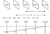
- FIG. 5 is a diagram for explaining an example of motion vector value scaling processing.
- FIG. 5 illustrates an example in which the reference image of the encoding target block of the encoding target image is the image Ref2, and the reference image for motion compensation prediction of the adjacent block (adjacent pixel) is the image Ref3.
- the adjacent block (adjacent pixel) is close to the value of the motion vector when motion compensation prediction is performed with reference to the image Ref2, and as a result, the value of the motion vector of the block to be encoded that refers to the image Ref2 is obtained.
- the participating image in the motion compensation prediction of the adjacent block is the image Ref3 and the value of the motion vector is (24, ⁇ 9), it is scaled to 2/3 (16, 6).
- the motion vector value of the image Ref2 referred to by the encoding target block may be used.
- the second encoded bit string generation unit 108 encodes the difference vector obtained by calculating the difference between the prediction vector and the motion vector of the target block by entropy encoding such as arithmetic encoding.
- a prediction vector is calculated by mixing a motion vector used in motion compensation prediction by parallel movement and a motion vector used in motion compensation prediction by geometric transformation. Therefore, a motion vector used in motion compensated prediction based on parallel movement is predicted and encoded from a motion vector used in motion compensated prediction based on geometric transformation. In some cases, a motion vector used in motion compensation prediction by conversion is predicted and encoded.
- the motion vector to be encoded / decoded in motion compensated prediction by geometric transformation is set to the motion vector of the pixel located at the center of each macroblock partition or sub-macroblock partition.
- the motion vector of the pixel located at each center can be regarded as an average value of the motion vectors of all the pixels included in each partition, and has a strong correlation with the motion vector used in the motion compensation prediction by the parallel movement. Therefore, the difference vector between the motion vector used in the motion compensation prediction based on the geometric transformation and the motion vector used in the motion compensation prediction based on the parallel movement is likely to be a small value.
- the third encoded bit sequence generation unit 109 sequentially encodes the encoded prediction error signal supplied from the prediction error signal encoding unit 106 using entropy encoding such as arithmetic encoding to generate an encoded bit sequence To do.
- the encoded bit strings generated by the first encoded bit string generation unit 107, the second encoded bit string generation unit 108, and the third encoded bit string generation unit 109 are encoded by information other than prediction method information, motion vectors, and prediction error signals.
- the other encoded bit strings are multiplexed via the output switch 113 to generate an encoded stream.
- the prediction error signal decoding unit 110 performs decompression decoding processing such as inverse quantization and inverse orthogonal transform on the prediction error signal encoded by the prediction error signal encoding unit 106, and decodes the prediction error signal. To do.
- the prediction error signal decoding unit 110 supplies the decoded prediction error signal to the decoded image signal generation unit 111.
- the decoded image signal generation unit 111 superimposes the prediction error signal supplied from the prediction error signal encoding unit 106 and the prediction signal supplied from the prediction method determination unit 104 to generate a decoded image signal.
- the decoded image signal generation unit 111 sequentially stores the decoded image signal in the decoded image buffer 112 in units of pixel blocks.
- the decoded image stored in the decoded image buffer 112 is used as a reference image when performing motion compensation prediction on the subsequent image in the encoding order, if necessary.
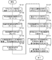
- FIG. 6 is a flowchart showing a macroblock encoding processing procedure in the image encoding apparatus 100 according to Embodiment 1 of the present invention.
- the translational motion compensation prediction unit 102 and the geometric transformation motion compensation prediction unit 103 extract a macroblock signal from the image buffer 101 (S101).
- the translational motion compensation prediction unit 102 performs motion compensation prediction by translation between the macroblock signal supplied from the image buffer 101 and the reference image signal supplied from the decoded image buffer 112 (S102). The motion compensation prediction based on the parallel movement is performed for each mode.
- the geometric transformation motion compensation prediction unit 103 performs motion compensation prediction by geometric transformation between the macroblock signal supplied from the image buffer 101 and the reference image signal supplied from the decoded image buffer 112 (S103). . Motion compensation prediction by this geometric transformation is performed for each mode.
- the prediction method determination unit 104 determines which of the motion compensation prediction method based on parallel movement and the motion compensation prediction based on geometric transformation is to be adopted (S104). At that time, it is also decided which mode is adopted.
- the prediction error signal generation unit 105 subtracts the prediction signal supplied from the prediction method determination unit 104 from the target image signal supplied from the image buffer 101 to generate a prediction error signal (S105).
- the prediction error signal encoding unit 106 encodes the prediction error signal (S106).
- the first encoded bit string generation unit 107 encodes the prediction method information supplied from the prediction method determination unit 104 and generates an encoded bit string (S107).
- the second encoded bit string generation unit 108 encodes the motion vector supplied from the prediction method determination unit 104 and generates an encoded bit string (S108).
- the third encoded bit string generation unit 109 entropy-encodes the prediction error signal encoded by the prediction error signal encoding unit 106 using arithmetic encoding or the like to generate an encoded bit string (S109).
- the prediction error signal decoding unit 110 decodes the prediction error signal encoded by the prediction error signal encoding unit 106 (S110).
- the decoded image signal generation unit 111 generates a decoded image signal by superimposing the prediction error signal decoded by the prediction error signal decoding unit 110 and the prediction signal supplied from the prediction method determination unit 104 (S111).
- the decoded image signal generation unit 111 accumulates the generated decoded image signal in the decoded image buffer 112 (S112).
- the compression efficiency of the code amount can be improved by the image coding method using the motion compensation prediction by the geometric transformation. That is, the amount of codes can be reduced by predictively encoding motion vectors that use motion compensated prediction by geometric transformation. Also, if the motion compensation prediction based on the parallel movement and the motion compensation prediction based on the geometric transformation are used in combination, the compression efficiency of the code amount can be further improved. At that time, by sharing a motion vector related to motion compensation prediction based on parallel movement and a motion vector encoding method related to motion compensation prediction based on geometric transformation, even if these two prediction methods are mixed, The motion vector predictive coding method can be used as it is.
- the motion vector of the pixel at or near the center of the partition into which the pixel block is divided is treated as the motion vector of the pixel block.
- the motion vector of the pixel located at each center can be regarded as an average value of the motion vectors of all the pixels included in each partition. Therefore, the correlation with the motion vector of the pixel block adjacent to the pixel block and adopting the motion compensation prediction method by parallel movement is also high. Therefore, even if the motion compensation prediction based on the parallel movement and the motion compensation prediction based on the geometric transformation are used together, an increase in the code amount of the motion vector can be suppressed.
- motion compensated prediction by geometric transformation can be applied to 8 ⁇ 16 mode and 16 ⁇ in the 8 ⁇ 8 mode macroblock type (in this type, four motion vectors are generated).
- An 8-mode macroblock type in these types two motion vectors are generated
- 4 ⁇ 4 mode sub-macroblock types in which four motion vectors are generated
- 4 ⁇ 8 mode sub-macroblock types are also applied to 4 ⁇ 8 mode and 8 ⁇ 4 mode sub-macroblock types (in these types).
- Two motion vectors are generated).
- AVC / H It corresponds to all macroblock partitions and sub-macroblock partitions adopted in H.264, etc., and is highly harmonious and compatible with existing coding schemes. Therefore, the introduction cost can be suppressed.
- FIG. 7 is a block diagram showing the configuration of the image decoding apparatus 200 according to Embodiment 2 of the present invention.
- the image decoding apparatus 200 decodes the encoded stream generated by the image encoding apparatus 100 according to Embodiment 1.
- motion compensated prediction based on parallel movement and motion compensated prediction based on geometric transformation may be used together, or motion compensated prediction based on geometric transformation is used alone. There is also. Note that intra coding is not considered.
- the image decoding apparatus 200 includes an input switch 209, a decoding unit 250, a translational motion compensation prediction unit 204, a geometric transformation motion compensation prediction unit 205, a decoded image signal generation unit 207, a decoded image buffer 208, a switching control unit 214, A prediction unit switch 210, a second prediction unit switch 211, a third prediction unit switch 212, and a fourth prediction unit switch 213 are provided.
- the decoding unit 250 includes a first encoded bit string decoding unit 201, a second encoded bit string decoding unit 202, a third encoded bit string decoding unit 203, and a prediction error signal decoding unit 206.
- the decoding unit 250 decodes prediction method information, motion vectors, and prediction error signals included in the encoded stream.
- the difference vector is encoded in the encoded stream.
- the difference vector is a difference between the motion vector of the target block and a prediction vector predicted from the motion vector of the adjacent block or the adjacent pixel.
- the decoding unit 250 calculates a prediction vector from the motion vector of the adjacent block or the adjacent pixel, and adds the decoded difference vector to the prediction vector, thereby performing prediction encoding.
- the motion vector of the target block is decoded. As described above, the motion vector of the target block is predictively encoded with reference to the motion vector of the adjacent block regardless of the motion compensation prediction method of the adjacent block.
- the decoding unit 250 decodes the motion vector of the target block subjected to predictive encoding with reference to the motion vector of the adjacent block regardless of the motion compensation prediction method of the adjacent block. In the case of geometric conversion motion compensation, the motion vector of the target block becomes the motion vector of the representative pixel.
- the translational motion compensation prediction unit 204 obtains a prediction signal from the motion vector between the target block in the target image and the reference block in the reference image that is translated with the target block, and the image signal of the reference block. Generate.
- the geometric transformation motion compensation prediction unit 205 performs prediction based on the motion vector between the target block in the target image, the reference block in the reference image having a geometric transformation relationship with the target block, and the image signal of the reference block. Generate a signal.
- the target block is divided into a plurality of small blocks, and a representative pixel is selected for each small block.
- the representative pixel is selected as a pixel at the approximate center or the approximate center of gravity of the small block, and the encoded stream includes a motion vector of each representative pixel.
- the geometric transformation motion compensation prediction unit 205 calculates a motion vector of pixels other than the plurality of representative pixels of the target block by at least one of interpolation and extrapolation using the motion vectors of the plurality of representative pixels. For example, the motion vectors of the pixels other than the representative pixel are calculated by the arithmetic expressions shown in the above expressions (1) to (10).
- the switching control unit 214 refers to the prediction method information decoded by the decoding unit 250, and for each target block in the target image, the prediction method by the translational motion compensation prediction unit 204 and the geometric transformation motion compensation prediction unit 205. Specify which of the prediction methods is used.
- the switching control unit 214 also designates which mode is designated. For example, in the prediction method information for designating motion compensation prediction by the geometric transformation motion compensation prediction unit 205, the target block is divided into four equal parts in a cross and divided into four square small blocks, and four motion vectors are detected. The first mode, the target block is horizontally divided into two vertically divided small rectangular blocks, and two motion vectors are detected. The target block is vertically divided into two equal parts. Any one of the third modes in which two motion vectors are detected after being divided into two horizontally long rectangular small blocks is designated.
- the first encoded bit string decoding unit 201, the second encoded bit string decoding unit 202, and the third encoded bit string decoding unit 203 are included in the encoded stream generated by the image encoding device 100 according to Embodiment 1.
- the encoded bit string to be transmitted is selectively input via the input switch 209.
- the first encoded bit string decoding unit 201 decodes the encoded bit string supplied via the input switch 209 by entropy decoding such as arithmetic decoding, and acquires prediction method information.
- the prediction method information includes whether the encoding is performed by translation / geometric transformation, and in the case of translation motion compensation, 16 ⁇ 16/16 ⁇ 8/8 ⁇ 16. Information on which of the / 8 ⁇ 8 mode is used is included.
- a first mode for encoding / decoding the motion vectors of the four representative pixels a, b, c, d, and encoding the motion vectors of the two representative pixels e, f in the vertical direction of the target block The information includes information on the second mode for decoding and the third mode for encoding / decoding the motion vectors of the two representative pixels g and h in the horizontal direction of the target block.
- the second encoded bit string decoding unit 202 decodes the encoded bit string supplied via the input switch 209 by entropy decoding such as arithmetic decoding to obtain a motion vector.
- the motion vector is described by a difference vector between the prediction vector calculated from the motion vector of the adjacent block and the motion vector of the decoding target block.
- the second encoded bit string decoding unit 202 decodes the encoded bit string supplied via the input switch 209 by entropy decoding such as arithmetic decoding, and obtains a difference vector. Further, the second encoded bit string decoding unit 202 performs motion vectors of neighboring blocks or adjacent pixels that have already been encoded / decoded according to the prediction method information supplied from the first encoded bit string decoding unit 201. The prediction vector is calculated by predicting the motion vector of the target block.
- the calculation of the prediction vector in the second encoded bit string decoding unit 202 is performed by the same method as the calculation of the prediction vector in the second encoded bit string generation unit 108 of the image encoding device 100. Then, the motion vector is obtained by adding the difference vector decoded from the encoded bit string to the prediction vector.
- the encoding side calculates the prediction vector by mixing the motion vector used in the motion compensation prediction by translation and the motion vector used in the motion compensation prediction by geometric transformation. A motion vector used in motion compensated prediction and a motion vector used in motion compensated prediction based on geometric transformation are mixed to calculate a predictive vector, and the motion vector is obtained by adding the decoded difference vector to the predicted vector.
- parallel motion compensation prediction the motion vector of the block can be acquired, and in the case of geometric transformation motion compensation prediction, the motion vector of the representative pixel of the block can be acquired.
- the switching control unit 214 performs the first prediction unit switch 210, the second prediction unit switch 211, the third prediction unit switch 212, and the fourth prediction unit according to the prediction method information supplied from the first encoded bit string decoding unit 201.
- Switch 213 is switched.
- the motion compensation prediction method by translation is selected as the prediction method of the target block
- switching is performed so that the path of the translation motion compensation prediction unit 204 is selected, and the motion compensation prediction method by geometric transformation is selected. In this case, the path of the geometric transformation motion compensation prediction unit 205 is switched to be selected.
- the translation motion compensated prediction unit 204 includes a decoded image to be a reference image supplied from the decoded image buffer 208 via the fourth prediction unit switch 213, and a second encoded bit string decoding unit 202 to the second prediction unit switch 211. Using the decoded motion vector supplied via, motion compensated prediction by translation is performed.
- the geometric transformation motion compensated prediction unit 205 includes a decoded image to be a reference image supplied from the decoded image buffer 208 via the fourth prediction unit switch 213, and a second prediction bit switch from the second encoded bit string decoding unit 202.
- the motion vectors of the representative pixels supplied via 211 are either interpolated or extrapolated according to the above equations (1) to (4).
- motion compensation prediction by geometric transformation is performed by performing motion compensation for each pixel according to the motion vector for each pixel.
- the third encoded bit string decoding unit 203 sequentially decodes the encoded bit string supplied via the input switch 209, and acquires the encoded prediction error signal.
- the prediction error signal decoding unit 206 performs decompression decoding processing such as inverse quantization and inverse orthogonal transform on the encoded prediction error signal supplied from the third encoded bit string decoding unit 203, and performs the decoded prediction Get the error signal.
- the decoded image signal generation unit 207 generates an image signal from the prediction signal and the prediction error signal. More specifically, the decoded image signal generation unit 207 switches from the translation motion compensation prediction unit 204 or the geometric transformation motion compensation prediction unit 205 to the third prediction unit switch according to the prediction method specified by the switching control unit 214. The prediction error signal supplied from the prediction error signal decoding unit 206 is superimposed on the prediction signal supplied via 212 to generate a decoded image signal. The decoded image signal generation unit 207 sequentially stores the decoded image signal in the decoded image buffer 208 in units of pixel blocks.
- FIG. 8 is a flowchart showing a macroblock decoding process procedure in the image decoding apparatus 200 according to Embodiment 2 of the present invention.
- the first encoded bit string decoding unit 201 decodes the encoded bit string supplied via the input switch 209 and acquires prediction method information (S201).
- the second encoded bit string decoding unit 202 decodes the encoded bit string supplied via the input switch 209 and obtains a difference vector (S202).
- the second encoded bit string decoding unit 202 calculates a prediction vector from the neighboring blocks or neighboring pixels (S202), adds the difference vector supplied from the prediction method determining unit 104 to the prediction vector, and obtains the target block or target pixel. Is calculated (S202).
- the switching control unit 214 refers to the decoded prediction method information and identifies the motion compensation prediction method of the target block (S203).
- the prediction method is a motion compensation prediction method based on translation (translation in S203)
- the translation motion compensation prediction unit 204 determines a decoded image signal to be a reference image signal supplied from the decoded image buffer 208 as a reference image signal.
- the motion vector supplied from the 2-encoded bit string decoding unit 202 is used to perform motion compensation by translation and generate a prediction signal (S204).
- the geometric transformation motion compensation prediction unit 205 uses the reference image supplied from the decoded image buffer 208.
- the decoded image signal to be a signal is motion-compensated by geometric transformation using the motion vector supplied from the second encoded bit string decoding unit 202 to generate a prediction signal (S205).
- the third encoded bit string decoding unit 203 decodes the encoded bit string supplied via the input switch 209 and acquires the encoded prediction error signal (S206).
- the decoded image signal generation unit 207 decodes the acquired prediction error signal (S207).
- the decoded image signal generation unit 207 superimposes the prediction error signal decoded by the decoded image signal generation unit 207 and the prediction signal generated by the translational motion compensation prediction unit 204 or the geometric transformation motion compensation prediction unit 205.
- a decoded image signal is generated (S208).
- the decoded image signal generation unit 207 accumulates the generated decoded image signal in the decoded image buffer 208 (S209).
- the decoded image signal stored in the decoded image buffer 208 is used as a reference image signal in the translational motion compensation prediction unit 204 and the geometric transformation motion compensation prediction unit 205.
- the encoded stream generated by the image encoding apparatus 100 according to the first embodiment can be efficiently decoded.
- achieved by the image coding apparatus 100 which concerns on Embodiment 1 mentioned above is supported from the decoding side, and the effect can be ensured. That is, in the image coding method using motion compensation prediction by geometric transformation, the effect of improving the compression efficiency of the code amount can be supported from the decoding side, and the effect can be ensured. Also, in the image coding method that uses motion compensation prediction by parallel movement and motion compensation prediction by geometric transformation, the effect of improving the compression efficiency of the code amount can be supported from the decoding side, and the effect can be guaranteed. it can. Moreover, the harmony and compatibility with the existing image decoding apparatus are high, and the introduction cost can be suppressed.
- the shape of the target block is a square
- the shape of the target block may be other shapes such as a triangle, a parallelogram, and a trapezoid.
- the shape of the small block (that is, the macroblock partition and the sub-macroblock partition) is not limited to a square and a rectangle, but other shapes such as a triangle, a parallelogram, and a trapezoid. But you can. In this case, it is preferable that the representative pixel is set at or near the center of gravity of the shape.
- the approximate center and approximately center of gravity pixel of the small block are used as the representative pixels.
- the present invention is not limited to this and corresponds to the center or center of gravity.
- the interpolation pixel located at the coordinates may be used as the representative pixel, or the interpolation pixel corresponding to the vertex of the macroblock or its surrounding pixels may be used as the representative pixel.
- 100 image encoding device 101 image buffer, 102 translational motion compensation prediction unit, 103 geometric transformation motion compensation prediction unit, 104 prediction method determination unit, 105 prediction error signal generation unit, 106 prediction error signal encoding unit, 107th 1 encoded bit string generation unit, 108 second encoded bit string generation unit, 109 third encoded bit string generation unit, 110 prediction error signal decoding unit, 111 decoded image signal generation unit, 112 decoded image buffer, 113 output switch, 150 code , 200 image decoding device, 201 first encoded bit string decoding unit, 202 second encoded bit string decoding unit, 203 third encoded bit string decoding unit, 204 translation motion compensation prediction unit, 205 geometric transformation motion compensation prediction Part, 206 misprediction Signal decoding unit, 207 decoded image signal generation unit, 208 decoded image buffer, 209 input switch, 210 first prediction unit switch, 211 second prediction unit switch, 212 third prediction unit switch, 213 fourth prediction unit switch, 214 switching Control unit, 250 decryption unit.
- the present invention can be used in the field of encoding an image using motion compensation prediction.
Landscapes
- Engineering & Computer Science (AREA)
- Multimedia (AREA)
- Signal Processing (AREA)
- Compression Or Coding Systems Of Tv Signals (AREA)
Abstract
予測方法決定部104は、対象画像内の対象ブロックごとに、平行移動動き補償予測部102による予測方法と、幾何学変換動き補償予測部103による予測方法とのいずれを採用するか決定する。符号化部150は、予測方法決定部104により採用された予測方法を特定するための予測方法情報、当該予測方法に係る動きベクトル、および予測誤差信号生成部105により生成された予測誤差信号を符号化する。符号化部150は、対象ブロックの動きベクトルを隣接ブロックの動きベクトルを参照して予測符号化する際、当該隣接ブロックの動き補償予測方法が平行移動動き補償予測であるか幾何学変換動き補償予測であるかに関わらずに、参照すべき動きベクトルを決定する。
Description
本発明は、動き補償予測を用いて画像を符号化する画像符号化装置、画像符号化方法および画像符号化プログラム、ならびにその符号化された画像を復号する画像復号装置、画像復号方法および画像復号プログラムに関する。
動画像の圧縮符号化方式の代表的なものとして、MPEGシリーズの規格がある。MPEGシリーズの規格では、フレームを複数のブロックに分割し、他のフレームからの動きを予測する動き補償が用いられている。MPEG-4やAVC/H.264では、複数の動き補償ブロックサイズの中から、最適なものを切り替えて用いる仕組みが導入されている。
ブロック単位の動き補償予測では、対象ブロックと参照ブロックとの間の平行移動を補償する方式が一般的である。これに加えて、ブロックの変形(たとえば、拡大、縮小、回転)を補償する方式も検討されている。たとえば、特許文献1では、フレーム間の予測を用いた画像符号化方式として、平行移動によって予測画像を求めるモードと幾何学変換によって予測画像を求めるモードをブロックごとに適応的に切り替えて、予測効率の向上を図っている。この方式では、平行移動の動きベクトルと、格子点の動きベクトル(すなわち、幾何学変換で用いる動きベクトル)を符号化するとしている。
このような状況下、本発明者は、平行移動による動き補償予測と幾何学変換による動き補償予測を併用する画像符号化方式にて、動きベクトル情報を圧縮することにより、さらに全体の符号量を圧縮する手法を見出した。
本発明はこうした状況に鑑みなされたものであり、その目的は、平行移動による動き補償予測と幾何学変換による動き補償予測を併用する画像符号化方式にて、符号量の圧縮効率を向上させる技術を提供することにある。
本発明のある態様の画像符号化装置は、動画像を符号化する画像符号化装置であって、対象画像内の対象ブロックと、その対象ブロックと平行移動した関係にある参照画像内の参照ブロックとの間の、動きベクトルおよび予測信号を生成する平行移動動き補償予測部と、対象画像内の対象ブロックと、その対象ブロックと幾何学変換した関係にある参照画像内の参照ブロックとの間の、動きベクトルおよび予測信号を生成する幾何学変換動き補償予測部と、対象画像内の対象ブロックごとに、平行移動動き補償予測部による予測方法と、幾何学変換動き補償予測部による予測方法とのいずれを採用するか決定する予測方法決定部と、予測方法決定部により採用された予測方法で生成された予測信号と、対象ブロックの画像信号との差分を算出し、予測誤差信号を生成する予測誤差信号生成部と、予測方法決定部により採用された予測方法を特定するための予測方法情報、当該予測方法に係る動きベクトル、および予測誤差信号生成部により生成された予測誤差信号を符号化する符号化部と、を備える。符号化部は、対象ブロックの動きベクトルを隣接ブロックの動きベクトルを参照して予測符号化する際、当該隣接ブロックの動き補償予測方法が平行移動動き補償予測であるか幾何学変換動き補償予測であるかに関わらずに、参照すべき動きベクトルを決定する。
幾何学変換動き補償予測部は、対象ブロックから複数の代表画素を選定して、それぞれの代表画素の動きベクトルを検出し、対象ブロックの複数の代表画素以外の画素の動きベクトルを、それら複数の代表画素の動きベクトルを用いた内挿および外挿の少なくともいずれか一方により算出してもよい。
幾何学変換動き補償予測部は、対象ブロックを小ブロックに分割した場合の小ブロックの略中心または略重心に相当する画素を代表画素に選定してもよい。
対象ブロックは、正方形の領域であり、幾何学変換動き補償予測部は、対象ブロックを十字に四等分した四つの正方形の小ブロックの四つの代表画素ごとに動きベクトルを検出する第1モードと、対象ブロックを横に二等分した二つの縦長長方形の小ブロックの二つの代表画素ごとに動きベクトルを検出する第2モードと、対象ブロックを縦に二等分した二つの横長長方形の小ブロックの二つの代表画素ごとに動きベクトルを検出する第3モードと、を実行し、予測方法決定部は、幾何学変換動き補償予測部による予測方法として、第1モード、第2モードおよび第3モードのいずれかを採用してもよい。
本発明の別の態様は、画像復号装置である。この画像復号装置は、平行移動による動き補償予測と幾何学変換による動き補償予測が併用されて符号化された符号化ストリームに含まれる、予測方法情報、動きベクトルおよび予測誤差信号を復号する復号部と、対象画像内の対象ブロックと、その対象ブロックと平行移動した関係にある参照画像内の参照ブロックとの間の動きベクトル、および参照ブロックの画像信号から予測信号を生成する平行移動動き補償予測部と、対象画像内の対象ブロックと、その対象ブロックと幾何学変換した関係にある参照画像内の参照ブロックとの間の動きベクトル、および参照ブロックの画像信号から予測信号を生成する幾何学変換動き補償予測部と、復号部により復号された予測方法情報を参照して、対象画像内の対象ブロックごとに、平行移動動き補償予測部による予測方法と、幾何学変換動き補償予測部による予測方法とのいずれを用いるか指定する制御部と、制御部により指定された予測方法により生成された予測信号、および復号部により復号された予測誤差信号から画像信号を生成する画像信号生成部と、を備える。対象ブロックの動きベクトルは、隣接ブロックの動き補償予測方法が平行移動動き補償予測であるか幾何学変換動き補償予測であるかに関わらずに、当該隣接ブロックの動きベクトルを参照して予測符号化されており、復号部は、予測符号化された対象ブロックの動きベクトルを、隣接ブロックの動き補償予測方法に関わらずに、当該隣接ブロックの動きベクトルを参照して復号する。
対象ブロックは、複数の代表画素が選定され、それぞれの代表画素の動きベクトルが予測符号化されて符号化ストリームに含まれており、幾何学変換動き補償予測部は、対象ブロックの複数の代表画素以外の画素の動きベクトルを、それら複数の代表画素の復号された動きベクトルを用いた内挿および外挿の少なくともいずれか一方により算出してもよい。
代表画素は、対象ブロックを小ブロックに分割した場合の小ブロックの略中心または略重心に相当する画素に選定されていてもよい。
対象ブロックは、正方形の領域であり、幾何学変換動き補償予測部による動き補償予測を指定する予測方法情報には、対象ブロックが十字に四等分された四つの正方形の小ブロックの四つの代表画素ごとに動きベクトルが検出される第1モードと、対象ブロックが横に二等分された二つの縦長長方形の小ブロックの二つの代表画素ごとに動きベクトルが検出される第2モードと、対象ブロックが縦に二等分された二つの横長長方形の小ブロックの二つの代表画素ごとに動きベクトルが検出される第3モードのいずれかが指定されていてもよい。
なお、以上の構成要素の任意の組み合わせ、本発明の表現を方法、装置、システム、記録媒体、コンピュータプログラムなどの間で変換したものもまた、本発明の態様として有効である。
平行移動による動き補償予測と幾何学変換による動き補償予測を併用する画像符号化方式にて、符号量の圧縮効率を向上させることができる。
以下、図面と共に本発明の実施の形態を説明する。以下の実施の形態では、AVC/H.264符号化方式をベースとして符号化/復号する例を説明する。
図1は、本発明の実施の形態1に係る画像符号化装置100の構成を示すブロック図である。画像符号化装置100は、画像バッファ101、平行移動動き補償予測部102、幾何学変換動き補償予測部103、予測方法決定部104、予測誤差信号生成部105および符号化部150を備える。符号化部150は、予測誤差信号符号化部106、第1符号化ビット列生成部107、第2符号化ビット列生成部108、第3符号化ビット列生成部109、予測誤差信号復号部110、復号画像信号生成部111、復号画像バッファ112および出力スイッチ113を含む。
これらの構成は、ハードウェア的には、任意のプロセッサ、メモリ、その他のLSIで実現でき、ソフトウェア的にはメモリにロードされたプログラムなどによって実現されるが、ここではそれらの連携によって実現される機能ブロックを描いている。したがって、これらの機能ブロックがハードウェアのみ、ソフトウェアのみ、またはそれらの組み合わせによっていろいろな形で実現できることは、当業者には理解されるところである。
画像バッファ101は、撮影/表示時間順に供給された符号化対象の画像信号を一時格納する。画像バッファ101は、格納された符号化対象の画像信号を、所定の画素ブロック単位(ここでは、マクロブロック単位)で、平行移動動き補償予測部102、幾何学変換動き補償予測部103および予測誤差信号生成部105に並列に供給する。その際、撮影/表示時間順に供給された画像は、符号化順序に並び替えられて画像バッファ101から出力される。
MPEGシリーズでは、マクロブロックとは16×16画素の輝度信号と、それに対応する2つの色差信号のブロックを指す。色差フォーマットのYUVが4:2:0の場合、色差信号は8×8画素のサイズである。
本実施の形態では、参照画像を用いずに画面内で符号化するイントラ符号化方式、参照画像を用いた平行移動による動き補償予測方式、および参照画像を用いた幾何学変換による動き補償予測方式を用いる。ここで、参照画像は局部復号された復号画像である。なお、本実施の形態ではイントラ符号化方式には注目しないため、図1ではその構成を省略して描いている。これらの符号化方式のモードを、マクロブロック単位で単独あるいは組み合わせて適応的に切り替える。なお、すべてのマクロブロックを、参照画像を用いた幾何学変換による動き補償予測方式を用いて符号化する方式も可能である。
平行移動動き補償予測部102は、対象画像内の対象ブロックと、その対象ブロックと平行移動した関係にある参照画像内の参照ブロックとの間の、動きベクトルおよび予測信号を生成する。本実施の形態では、平行移動動き補償予測部102は、AVC/H.264方式などに規定されている既存の動き補償予測と同様の、平行移動による動き補償予測を行う。
動き補償予測は、後述する復号画像バッファ112から供給される表示順序で、前方または後方の復号画像を参照画像とする。平行移動動き補償予測部102は、参照画像内の所定の検出範囲内で、画像バッファ101から供給されるマクロブロック信号と、復号画像バッファ112から供給される参照画像信号との間でブロックマッチングを行う。平行移動動き補償予測部102は、ブロックマッチングにより、当該マクロブロック信号と最も誤差が小さい、参照画像信号内の参照ブロック信号を特定し、当該マクロブロック信号と当該参照ブロック信号との間の動きベクトルを検出する。
このブロックマッチングを、規定された複数のモードで行う。複数のモードはそれぞれ、参照インデックス、動き補償ブロックのサイズ、L0/L1予測などが異なる。参照インデックスとは参照ピクチャを示すインデックスである。なお、L0/L1予測はBスライスでのみ選択可能である。ブロックサイズの具体例は後述する。
また、動き補償予測を行う際、1画素未満の画素精度で動き補償することができる。たとえば、AVC/H.264方式などでは、輝度信号は1画素の1/4の精度まで、色差信号は1画素の1/8の精度までの動き補償を行うことができる。1画素未満の画素精度で動き補償する場合、参照画像内の整数画素の信号を用いて、1画素未満の画素精度の信号を周囲の信号から補間により生成する。
平行移動動き補償予測部102は、それぞれのモードにて動き補償予測を行い、それぞれのモードにおける予測信号(より具体的には、動き補償予測ブロック信号)および動きベクトルを、予測方法決定部104に供給する。
つぎに、AVC/H.264方式における動き補償ブロックサイズについて説明する。
図2は、マクロブロック・パーティションおよびサブマクロブロック・パーティションを説明するための図である。ここでは説明を簡略化するため、輝度信号の画素ブロックのみ描いている。AVC/H.264方式を含むMPEGシリーズでは、マクロブロックは正方形領域で規定される。一般的にAVC/H.264方式を含むMPEGシリーズでは、16×16画素(水平16画素、垂直16画素)で規定されるブロックをマクロブロックという。さらに、AVC/H.264方式では、8×8画素で規定されるブロックをサブマクロブロックという。マクロブロック・パーティションとは、マクロブロックを動き補償予測のために、さらに分割したそれぞれの小ブロックをいう。サブマクロブロック・パーティションとは、サブマクロブロックを動き補償予測のために、さらに分割したそれぞれの小ブロックをいう。
図2は、マクロブロック・パーティションおよびサブマクロブロック・パーティションを説明するための図である。ここでは説明を簡略化するため、輝度信号の画素ブロックのみ描いている。AVC/H.264方式を含むMPEGシリーズでは、マクロブロックは正方形領域で規定される。一般的にAVC/H.264方式を含むMPEGシリーズでは、16×16画素(水平16画素、垂直16画素)で規定されるブロックをマクロブロックという。さらに、AVC/H.264方式では、8×8画素で規定されるブロックをサブマクロブロックという。マクロブロック・パーティションとは、マクロブロックを動き補償予測のために、さらに分割したそれぞれの小ブロックをいう。サブマクロブロック・パーティションとは、サブマクロブロックを動き補償予測のために、さらに分割したそれぞれの小ブロックをいう。
図2(a)は、マクロブロックが16×16画素の輝度信号とそれに対応する2つの色差信号から構成される1つのマクロブロック・パーティションで構成されていることを示す図である。ここでは、この構成を16×16モードのマクロブロック・タイプと呼ぶ。
図2(b)は、マクロブロックが16×8画素(水平16画素、垂直8画素)の輝度信号とそれに対応する2つの色差信号から構成される2つのマクロブロック・パーティションで構成されていることを示す図である。この2つのマクロブロック・パーティションは縦に並べられている。ここでは、この構成を16×8モードのマクロブロック・タイプと呼ぶ。
図2(c)は、マクロブロックが8×16画素(水平8画素、垂直16画素)の輝度信号とそれに対応する2つの色差信号から構成される2つのマクロブロック・パーティションで構成されていることを示す図である。この2つのマクロブロック・パーティションは横に並べられている。ここでは、この構成を8×16モードのマクロブロック・タイプと呼ぶ。
図2(d)は、マクロブロックが8×8画素の輝度信号とそれに対応する2つの色差信号から構成される4つのマクロブロック・パーティションで構成されていることを示す図である。この4つのマクロブロック・パーティションは縦横2つずつ並べられている。この構成を8×8モードのマクロブロック・タイプと呼ぶ。なお、この8×8画素の輝度信号とそれに対応する2つの色差信号からなるマクロブロック・パーティションをサブマクロブロックと呼ぶ。
図2(e)は、サブマクロブロックが8×8画素の輝度信号とそれに対応する2つの色差信号から構成される1つのサブマクロブロック・パーティションで構成されていることを示す図である。ここでは、この構成を8×8モードのサブマクロブロック・タイプと呼ぶ。
図2(f)は、サブマクロブロックが8×4画素(水平8画素、垂直4画素)の輝度信号とそれに対応する2つの色差信号から構成される2つのサブマクロブロック・パーティションで構成されていることを示す図である。この2つのサブマクロブロック・パーティションは縦に並べられている。この構成を8×4モードのサブマクロブロック・タイプと呼ぶ。
図2(g)は、サブマクロブロックが4×8画素(水平4画素、垂直8画素)の輝度信号とそれに対応する2つの色差信号から構成される2つのマクロブロック・パーティションで構成されていることを示す図である。この2つのマクロブロック・パーティションは横に並べられている。ここでは、この構成を4×8モードのサブマクロブロック・タイプと呼ぶ。
図2(h)は、サブマクロブロックが4×4画素の輝度信号とそれに対応する2つの色差信号から構成される4つのサブマクロブロック・パーティションで構成されていることを示す図である。この4つのサブマクロブロック・パーティションは縦横2つずつ並べられている。ここでは、この構成を4×4モードのサブマクロブロック・タイプと呼ぶ。
AVC/H.264符号化方式では、以上の動き補償ブロックサイズの中から、最適なものを切り替えて用いる仕組みが取り入れられている。まず、マクロブロック単位の動き補償ブロックサイズとして、16×16、16×8、8×16および8×8モードのマクロブロック・タイプの中からいずれかが選択される。8×8モードのマクロブロック・タイプが選択された場合、サブマクロブロック単位の動き補償ブロックサイズとして、8×8、8×4、4×8、4×4モードのサブマクロブロック・タイプの中からいずれかが選択される。
輝度信号は、選択されたサイズの画素数で動き補償される。色差信号は、色差フォーマットが4:2:0の場合、水平、垂直ともにその半分の画素数で動き補償される。このように、動き補償ブロックサイズの情報は、マクロブロック・タイプおよびサブマクロブロック・タイプと呼ばれるシンタックス要素で符号化される。シンタックスとは符号化ビット列の表現規則であり、シンタックス要素とは、シンタックスで伝送することが規定されている情報である。
16×16、16×8、8×16および8×8モードのいずれのマクロブロック・タイプでも、L0予測、L1予測の場合、マクロブロック・パーティションごとに1つの動きベクトルが符号化・復号される。すなわち、16×16モードのマクロブロック・タイプでは1つの動きベクトルが、16×8および8×16モードのマクロブロック・タイプでは2つの動きベクトルが、および8×8モードのマクロブロック・タイプでは4つの動きベクトルが、それぞれ符号化・復号される。
各マクロブロック・パーティションの輝度信号および色差信号の各画素は、そのマクロブロック・パーティションの1つの動きベクトルに応じて、動き補償される。すなわち、当該各画素は、同じ動きベクトルを用いて動き補償される。
図1に戻り、幾何学変換動き補償予測部103は、対象画像内の対象ブロックと、その対象ブロックと幾何学変換した関係にある参照画像内の参照ブロックとの間の、動きベクトルおよび予測信号を生成する。より具体的には、幾何学変換動き補償予測部103は、対象ブロックを仮想的に複数の小ブロックに分割した場合の、小ブロックごとに代表画素を設定して、それぞれの代表画素の動きベクトルを検出する。その際、幾何学変換動き補償予測部103は、小ブロックの略中心または略重心の画素を代表画素に設定する。
また、幾何学変換動き補償予測部103は、複数の代表画素の動きベクトルから内挿および外挿の少なくとも一方を用いて、対象ブロックの複数の代表画素以外の画素の動きベクトルを算出する。なお、本発明の実施の形態に係る以下の説明においては、内挿・外挿との表記を内挿および外挿の少なくともいずれか一方のという意味で用いる。幾何学変換動き補償予測部103は、対象ブロックの4つの代表画素a、b、c、dの動きベクトルを符号化・復号する第1モード(後述する図3(a)参照)と、対象ブロックの縦方向における2つの代表画素e、fの動きベクトルを符号化・復号する第2モード(後述する図3(b)参照)と、対象ブロックの横方向における2つの代表画素g、hの動きベクトルを符号化・復号する第3モード(後述する図3(c)参照)を実行することができる。ここで、第1モードは対象ブロックを仮想的に十字に4等分して4つの正方形の小ブロックに分割した場合の、4つの小ブロックごとの中心または略中心を代表画素とし、第2モードは対象ブロックを仮想的に縦に2等分して2つの横長長方形の小ブロックに分割した場合の、2つの小ブロックごとの中心または略中心を代表画素とし、第3モードは対象ブロックを仮想的に横に2等分して2つの縦長長方形の小ブロックに分割した場合の、2つの小ブロックごとの中心または略中心を代表画素とする。
ここで、本発明の実施の形態に係る説明においては上記対象ブロックを16×16画素のマクロブロックとして説明するが、当該対象ブロックのサイズは16×16画素に限定されるものではなく、8×8画素のサブマクロブロックであってもよいし、32×32画素、48×48画素、64×64画素等のブロックであってもよい。上記小ブロックがマクロブロック・パーティションとして説明するが、それに限定されるものではなく、上記ブロックがサブマクロブロック、上記小ブロックがサブマクロブロック・パーティションであってもよい。
予測方法決定部104は、幾何学変換動き補償予測部103による予測方法として、上述した第1モード、第2モードおよび第3モードのいずれかを採用することができる。予測方法決定部104の詳細な処理については後述する。
以下、幾何学変換動き補償予測部103について、より具体的に説明する。幾何学変換動き補償予測部103は、AVC/H.264方式などに規定された既存の平行移動による動き補償予測と異なり、平行移動に加えて、拡大・縮小/回転などを含む変形を伴う幾何学変換による動き補償予測を行う。
本実施の形態に係る幾何学変換による動き補償予測では、マクロブロック、マクロブロック・パーティション、サブマクロブロックの輝度信号、色差信号の各画素をそれぞれ同じ動きベクトルで動き補償するのではなく、画素ごとに異なる動きベクトルを作成して動き補償を行う。幾何学変換動き補償予測の第1モードは8×8モードのマクロブロック・タイプに、第2モードは16×8のマクロブロック・タイプに、第3モードは8×16のマクロブロック・タイプに対応する。つまり、幾何学変換による動き補償予測ではマクロブロック・タイプは、画素ブロックの形状により規定されるのではなく、動きベクトルの数、代表画素の位置および動きベクトルの内挿・外挿演算方法により規定される。非代表画素の動きベクトルは、代表画素の動きベクトルにより内挿および外挿の少なくともいずれか一方により算出される。
幾何学変換動き補償予測部103は、サブマクロブロックを含む各マクロブロック・パーティションの中心または中心近傍の画素を代表画素に選定し、その動きベクトルを求める。マクロブロック・パーティションの場合、その縦横の画素数が偶数であるため、厳密な中心画素は存在しない。そこで、中心に位置する4画素のうちの特定の1画素を代表画素に設定するか、補間演算により厳密な中心画素の座標を求めて仮想的な画素を代表画素に設定する。幾何学変換動き補償予測部103は、各マクロブロック・パーティションの代表画素の動きベクトルとして、オプティカルフロー法等により画素単位で算出した動きベクトルを用いてもよいし、画像のエッジやコーナー等の信頼性の高いと判断できる特徴点の動きベクトルから内挿・外挿演算により補正してもよい。平行移動動き補償予測部102により生成された、対応するマクロブロック・パーティションの動きベクトルを用いてもよい。なお、対応するマクロブロック・パーティションの動きベクトルを用いる場合、その動きベクトルの値を当該代表画素にあてはめて、その動きベクトルの値を増加方向および減少方向に調整しながら検証することにより、動きベクトルの値を補正してもよい。
つぎに、幾何学変換動き補償予測部103は、代表画素の動きベクトルからマクロブロック内の非代表画素の動きベクトルを線形内挿・外挿(本実施の形態では、バイリニア内挿・外挿)により算出する。
縦方向の2つの代表画素e、fの動きベクトルを符号化・復号する第2モードの場合、幾何学変換動き補償予測部103は、垂直方向の2つの代表画素e、fの動きベクトルから、これら2点を結ぶ直線上の画素の動きベクトルを内挿および外挿の少なくともいずれか一方により算出する。そして、その他の画素の動きベクトルを、線形内挿・外挿された各画素の動きベクトルを水平方向にそのまま当てはめる。動きベクトルをそのまま当てはめた演算も内挿・外挿に含むものとする。
横方向の2つの代表画素g、hの動きベクトルを符号化・復号する第3モードの場合、幾何学変換動き補償予測部103は、水平方向の2つの代表画素の動きベクトルから、これら2点を結ぶ直線上の画素の動きベクトルを内挿および外挿の少なくともいずれか一方により算出し、その他の画素の動きベクトルを、線形内挿・外挿された各画素の動きベクトルを垂直方向にそのまま当てはめる。
4つの代表画素a、b、c、dの動きベクトルを符号化・復号する第1モードの場合、幾何学変換動き補償予測部103は、水平方向及び垂直方向の双方に内挿および外挿の少なくともいずれか一方により非代表画素の動きベクトルを算出する。後述する方法により水平方向および垂直方向の双方に一度に内挿・外挿してもよいし、水平方向の2つの代表画素の動きベクトルから、これら2点を結ぶ直線上の画素の動きベクトルを内挿・外挿することにより非代表画素の動きベクトルを算出し、その他の画素の動きベクトルを、既に算出された各画素の動きベクトルを用いて、さらに垂直方向に内挿・外挿することにより算出してもよい。
なお、縦方向の2つの代表画素e、fの動きベクトルを符号化・復号する第2モードにおいては、代表画素eの動きベクトルの値を代表画素a、bの動きベクトルの値に設定し、代表画素fの動きベクトルの値を代表画素c、dの動きベクトルの値に設定する。そして、4つの代表画素a、b、c、dの動きベクトルを符号化・復号する第1モードと同様に、非代表画素の動きベクトルを算出することができる。
同様に、横方向の2つの代表画素g、hの動きベクトルを符号化・復号する第3モードにおいては、代表画素gの動きベクトルの値を代表画素a、cの動きベクトルの値に設定し、第2代表画素hの動きベクトルの値を代表画素b、dの動きベクトルの値に設定する。そして、4つの代表画素a、b、c、dの動きベクトルを符号化・復号する第1モードと同様に、非代表画素の動きベクトルを算出することができる。
幾何学変換動き補償予測部103は、算出された画素ごとの動きベクトルを用いて、画素ごとに動き補償を行う。以上の説明では、マクロブロックに含まれる各画素の動きベクトルを算出する例を説明したが、サブマクロブロックに含まれる各画素の動きベクトルも同様に算出することができる。このような処理により、拡大・縮小/回転などを含む変形を表現することができ、幾何学変換と等価の処理を実現することができる。
この画素単位の動きベクトルの算出処理および各画素の動き補償処理を、規定された複数のモードで行う。複数のモードはそれぞれ、参照インデックス、動き補償ブロックのサイズ、L0/L1予測などが異なる。なお、L0/L1予測はBスライスでのみ選択可能である。
幾何学変換動き補償予測部103は、それぞれのモードにて動き補償予測を行い、それぞれのモードにおける予測信号(より具体的には、動き補償予測ブロック信号)および動きベクトルを、予測方法決定部104に供給する。
以下、幾何学変換動き補償予測における、各画素の動きベクトルの算出方法について具体例を挙げながら説明する。
図3(a)は、対象ブロックの4つの代表画素a、b、c、dの動きベクトルを符号化・復号する第1モードのマクロブロック・タイプの各画素の動きベクトルを算出する方法を説明するための図である。図3(a)では、代表画素を黒丸、非代表画素を白丸で表し、代表画素を、各マクロブロック・パーティションの中心近傍である画素a(3,3)、画素b(11,3)、画素c(3,11)および画素d(11,11)に設定している。ここでは、各画素の座標を(i,j)で表し、水平方向の座標を1画素単位でiで表し、垂直方向の座標を1画素単位でjで表している。マクロブロック中の最も左上の画素を原点(0,0)とし、右方向、及び下方向を正とする。
図3(a)は、対象ブロックの4つの代表画素a、b、c、dの動きベクトルを符号化・復号する第1モードのマクロブロック・タイプの各画素の動きベクトルを算出する方法を説明するための図である。図3(a)では、代表画素を黒丸、非代表画素を白丸で表し、代表画素を、各マクロブロック・パーティションの中心近傍である画素a(3,3)、画素b(11,3)、画素c(3,11)および画素d(11,11)に設定している。ここでは、各画素の座標を(i,j)で表し、水平方向の座標を1画素単位でiで表し、垂直方向の座標を1画素単位でjで表している。マクロブロック中の最も左上の画素を原点(0,0)とし、右方向、及び下方向を正とする。
まず、これら画素a、画素b、画素cおよび画素dの動きベクトルが割り当てられ、つぎに、それ以外の画素の動きベクトルが、線形内挿・外挿により算出される。
4つの代表画素a、b、c、dの動きベクトルを符号化・復号する第1モードでは、これら画素a、画素b、画素cおよび画素dの動きベクトルが割り当てられる。2つの代表画素e、fの動きベクトルを符号化・復号する第2モードでは、これら画素eおよび画素fの動きベクトルが割り当てられ、画素eの動きベクトルは画素a、bの動きベクトルでもあり、画素fの動きベクトルは画素c、dの動きベクトルでもある。2つの代表画素g、hの動きベクトルを符号化・復号する第3モードでは、これら画素gおよび画素hの動きベクトルが割り当てられ、画素gの動きベクトルは画素a、cの動きベクトルでもあり、画素hの動きベクトルは画素b、dの動きベクトルでもある。
次に、4つの代表画素a、b、c、dの動きベクトルVa、Vb、Vc、Vdからそれ以外の画素の動きベクトルV(i,j)が、線形内挿・外挿により算出される。
V(i,j)={(15-i-3)(15-j-3)Va+i(15-j-3)Vb+(15-i-3)(j-3)・Vc+(i-3)・(j-3)・Vd} ・・・式(1)
以上により、第1モード、第2モード、第3モードでの各画素毎の動きベクトルを算出する。なお、下記の方法により算出することもできる。
V(i,j)={(15-i-3)(15-j-3)Va+i(15-j-3)Vb+(15-i-3)(j-3)・Vc+(i-3)・(j-3)・Vd} ・・・式(1)
以上により、第1モード、第2モード、第3モードでの各画素毎の動きベクトルを算出する。なお、下記の方法により算出することもできる。
画素aの動きベクトルVa=V(3,3)、画素bの動きベクトルVb=V(11,3)、画素cの動きベクトルVc=V(3,11)、および画素dの動きベクトルVd=V(11,11)とすると、画素aと画素bを通るライン上の各画素の動きベクトルV(i,3)は、下記式(2)により算出される。
V(i,3)=Va+(Vb-Va)*(i-3)/8 ・・・式(2)
V(i,3)=Va+(Vb-Va)*(i-3)/8 ・・・式(2)
同様に、画素cと画素dを通るライン上の各画素の動きベクトルV(i,11)は、下記式(3)により算出される。
V(i,11)=Vc+(Vd-Vc)*(i-3)/8 ・・・式(3)
V(i,11)=Vc+(Vd-Vc)*(i-3)/8 ・・・式(3)
さらに、残りの画素の動きベクトルV(i,j)は、下記式(4)により算出される。
V(i,j)=V(i,3)+(V(i,11)-V(i,3))*(j-3)/8 ・・・式(4)
V(i,j)=V(i,3)+(V(i,11)-V(i,3))*(j-3)/8 ・・・式(4)
以上により、第1モード、第2モードおよび第3モードにおける各画素の動きベクトルを算出することができる。なお、第2モードおよび第3モードでは下記の方法により算出することもできる。
図3(b)は、対象ブロックの2つの代表画素e、fの動きベクトルを符号化・復号する第2モードのマクロブロック・タイプの各画素の動きベクトルを算出する方法を説明するための図である。図3(b)では、代表画素を、各マクロブロック・パーティションの中心近傍である画素e(7,3)および画素f(7,11)に設定している。
まず、これら画素eおよび画素fの動きベクトルが割り当てられ、つぎに、それ以外の画素の動きベクトルが、線形内挿・外挿により算出される。
画素eの動きベクトルVe=V(7,3)、画素fの動きベクトルをVf=V(7,11)とすると、画素eと画素fを通るライン上の各画素の動きベクトルV(7,j)は、下記式(5)により算出される。
V(7,j)=Ve+(Vf-Ve)*(j-3)/8 ・・・式(5)
V(7,j)=Ve+(Vf-Ve)*(j-3)/8 ・・・式(5)
つぎに下記式(6)に示すように、式(5)により算出された動きベクトルV(7,j)の値を水平方向に拡張して、動きベクトルV(7,j)の値を残りの画素の動きベクトルV(i,j)に代入する。
V(i,j)=V(7,j) ・・・式(6)
V(i,j)=V(7,j) ・・・式(6)
残りの画素の動きベクトルV(i,j)は、下記式(7)により算出されてもよい。
V(i,j)=Ve+(Vf-Ve)*(j-3)/8 ・・・式(7)
V(i,j)=Ve+(Vf-Ve)*(j-3)/8 ・・・式(7)
図3(c)は、対象ブロックの横方向における2つの代表画素g、hの動きベクトルを符号化・復号する第3モードのマクロブロック・タイプの各画素の動きベクトルを算出する方法を説明するための図である。図3(c)では、代表画素を、各マクロブロック・パーティションの中心近傍である画素g(3,7)および画素h(11,7)に設定している。
まず、これら画素gおよび画素hの動きベクトルが割り当てられ、つぎに、それ以外の画素の動きベクトルが、線形内挿・外挿により算出される。
画素gの動きベクトルVg=V(3,7)、画素hの動きベクトルVh=V(11,7)とすると、画素gと画素hを通るライン上の各画素の動きベクトルV(i,7)は、下記式(8)により算出される。
V(i,7)=Vg+(Vh-Vg)*(i-3)/8 ・・・式(8)
V(i,7)=Vg+(Vh-Vg)*(i-3)/8 ・・・式(8)
つぎに下記式(9)に示すように、式(8)により算出された動きベクトルV(i,7)の値を垂直方向に拡張して、動きベクトルV(i,7)の値を残りの画素の動きベクトルV(i,j)に代入する。
V(i,j)=V(i,7) ・・・式(9)
V(i,j)=V(i,7) ・・・式(9)
残りの画素の動きベクトルV(i,j)は、下記式(10)により算出されてもよい。
V(i,j) =Vg+(Vh-Vg)*(i-3)/8 ・・・式(10)
V(i,j) =Vg+(Vh-Vg)*(i-3)/8 ・・・式(10)
幾何学変換動き補償予測部103は、算出された各画素の動きベクトルに応じて各画素を動き補償予測する。より具体的には、各画素の動きベクトルが指し示す参照画像の画素から補間信号を生成することにより動き補償予測する。なお、各画素の動きベクトルの精度、演算過程で必要となる数値のまるめ方などは、どの復号装置で復号しても同じ値になるように規定する必要がある。なお、動きベクトルにより指定される予測画素の座標が小数点以下で表される場合、動き補償の際に周囲の画素から当該画素を補間する。その補間方法には4~6タップのフィルタリングや線形補間などを用いることができる。
4つの代表画素a、b、c、dの動きベクトルを符号化・復号する第1モードでは、4つの動きベクトルで拡大・縮小、回転、平行移動など、第2モード、第3モードでは表現できない変形を表すことができる。
対象ブロックの縦方向における2つの代表画素e、fの動きベクトルを符号化・復号する第2モードでは、2つの動きベクトルで平行移動に加えて垂直方向に均一な変形を表すことができる。変形の表現力は第1モードに比べて限定されるが、符号化すべき動きベクトルの数を減らすことができる。対象ブロックの横方向における2つの代表画素g、hの動きベクトルを符号化・復号する第3モードでは、2つの動きベクトルで平行移動に加えて水平方向に均一な変形を表すことができる。変形の表現力は第1モードに比べて限定されるが、符号化すべき動きベクトルの数を減らすことができる。
図1に戻り、予測方法決定部104は、対象画像内の対象ブロックごとに、平行移動動き補償予測部102による予測方法と、幾何学変換動き補償予測部103による予測方法とのいずれを採用するか決定する。より具体的には、いずれの予測方法の、いずれのモードを採用するかを決定する。以下、モードの選択を含めて予測方法の選択という。
すなわち、予測方法決定部104は、平行移動による動き補償予測または幾何学変換による動き補償予測のどちらを、どの参照画像を用いて、どの画素ブロック単位で符号化するかを選択することにより、予測方法を決定する。幾何学変換による動き補償予測の場合は、第1モード、第2モードおよび第3モードのいずれかを選択する。その際、それらの項目の、どの組み合わせが、最も効率的な符号化を実現できる予測方法であるかを判定することにより、予測方法を決定する。予測方法を決定する基準として、たとえば、符号量と歪の関係を考慮したレート歪理論を用いることができる。より具体的には、マクロブロックの符号量(すなわち、予測方法情報、動きベクトルおよび予測信号の合計符号量)を算出するとともに、符号化対象画像と復号画像の差から歪量を算出し、当該符号量および当該歪量を入力変数とするレート歪関数を最小化する予測方法を選択する。なお、予測方法はマクロブロック・タイプで記述される。平行移動動き補償の場合、16×16/16×8/8×16/8×8モードのいずれを用いるかに関してマクロブロック・タイプで記述され、幾何学変換動き補償の場合、第1モード、第2モードおよび第3モードのいずれを用いるかに関してマクロブロック・タイプで記述される。幾何学変換動き補償予測の第1モードは4本の動きベクトルを符号化する8×8モードのマクロブロック・タイプに、第2モードは2本の動きベクトルを符号化する16×8のマクロブロック・タイプに、第3モードは同じく2本の動きベクトルを符号化する8×16のマクロブロック・タイプとして記述される。
予測方法決定部104は、採用したマクロブロック・タイプで記述される予測方法情報およびその予測方法により生成された動きベクトルを第1符号化ビット列生成部107、及び第2符号化ビット列生成部108に、採用した予測方法に応じた動きベクトルを第2符号化ビット列生成部108に供給する。それとともに、予測方法決定部104は、採用した予測方法により生成された予測信号を予測誤差信号生成部105に供給する。
予測誤差信号生成部105は、予測方法決定部104により採用された予測方法で生成された予測信号と、対象ブロックの画像信号との差分を算出し、予測誤差信号を生成する。より具体的には、予測誤差信号生成部105は、画像バッファ101から供給される符号化対象の画像信号から、予測方法決定部104から供給される予測信号を減算することにより、予測誤差信号を生成し、予測誤差信号符号化部106に供給する。
符号化部150は、予測方法決定部104により採用された予測方法を特定するための予測方法情報、当該予測方法により生成された動きベクトル、および予測誤差信号生成部105により生成された予測誤差信号を符号化する。符号化部150の第2符号化ビット列生成部108は、対象ブロックの動きベクトルを符号化する際、隣接ブロックの動きベクトルを参照して予測符号化する。その際、当該隣接ブロックの動き補償予測方法が平行移動動き補償予測であるか幾何学変換動き補償予測であるかに関わらずに、両者を共通に扱い、参照すべき隣接ブロックの動きベクトルを決定する。したがって、対象ブロックの動きベクトルと隣接ブロックの動きベクトルとの参照関係は、平行移動動き補償予測方法が採用されたブロックの動きベクトルと、幾何学変換動き補償予測が採用された動きベクトルとの間でも成立する。すなわち、動きベクトルの予測符号化において、両者が混在している関係になる。
ここで、幾何学変換による動き補償予測が採用された対象ブロックでは、その代表画素の動きベクトルが予測符号化の対象となる。たとえば、平行移動による動き補償予測が採用された対象ブロックの動きベクトルを、幾何学変換による動き補償予測が採用された隣接ブロックの動きベクトルを参照して予測符号化する場合、その隣接ブロックの代表画素の動きベクトルを参照する。
以下、符号化部150の処理を詳細に説明する。予測誤差信号符号化部106は、予測誤差信号生成部105から供給される予測誤差信号に対して、直交変換、量子化などの圧縮符号化処理を行い、符号化された予測誤差信号を生成し、第3符号化ビット列生成部109および予測誤差信号復号部110に供給する。
第1符号化ビット列生成部107は、予測方法決定部104から供給されるマクロブロック・タイプで記述される予測方法情報を、算術符号化などのエントロピー符号化により符号化し、符号化ビット列を生成する。なお、予測方法情報に含めるべき、予測ブロックサイズ、L0/L1予測の区別なども組み合わせてマクロブロック・タイプとして符号化する。また、予測方法情報に含めるべき、平行移動による動き補償予測と幾何学変換による動き補償予測のいずれを用いるかを識別するための情報に関しては、以下の記述方法を用いることができる。例えば、マクロブロックタイプの符号化方法は共通化して平行移動による動き補償予測と幾何学変換による動き補償予測を判別するためのシンタックス要素を別途に用意して記述してもよいし、他のマクロブロック・タイプとして符号化する情報と組み合わせることで、マクロブロック・タイプを拡張して記述してもよい。
第2符号化ビット列生成部108は、予測方法決定部104から供給される動きベクトルを符号化し、符号化ビット列を生成する。その際、動きベクトルを予測符号化する。対象ブロックの動きベクトルを符号化する際、すでに符号化または復号済みの周囲の隣接ブロックの動きベクトルとの相関を利用して、当該隣接ブロックから動きベクトルを予測することにより予測ベクトルを算出する。なお、周囲の隣接ブロックの動きベクトルとの相関は、予測方法決定部104から供給される予測方法情報に基づき特定できる。そして、この予測ベクトルと対象ブロックまたは対象画素の動きベクトルとの差分である差分ベクトルを算出し、その差分ベクトルを符号化することにより、動きベクトルの符号量を削減する。ここで、幾何学変換による動き補償予測が採用された対象ブロックでは、その代表画素の動きベクトルが符号化の対象となる。
図4は、動きベクトルの予測方法を説明するための図である。図4(a)は、パーティションが設定されていないマクロブロック間において、動きベクトルを予測する例を示す。図4(b)は、パーティションが設定されているマクロブロック間において、動きベクトルを予測する例を示す。図4(c)は、16×8画素のマクロブロックにおいて、動きベクトルを予測する例を示す。図4(d)は、8×16画素のマクロブロックにおいて、動きベクトルを予測する例を示す。以下、図4(a)~(d)を参照して、AVC/H.264方式などに採用されている動きベクトルの予測方法について説明する。この動きベクトルの予測方法は、周囲の隣接ブロックの動きベクトルの中央値を用いて、対象ブロックの動きベクトルを予測する。
図4(a)~(d)にて、グレーで塗られているブロックの動きベクトルが符号化対象である。図4(a)にて、対象ブロックの動きベクトルを、その対象ブロックの左隣のブロックA、上隣のブロックBおよび右斜上隣のブロックCの3つの動きベクトルを用いて予測する。より具体的には、それら3つの動きベクトルから水平成分および垂直成分それぞれについて中央値をとって予測ベクトルとする。なお、Bピクチャーにおいては、L0予測のための動きベクトルとL1予測のための動きベクトルをそれぞれ別々に扱う。その対象ブロックの左隣のブロックA、上隣のブロックBおよび右斜上隣のブロックCの3つのL0予測のための動きベクトルを用いて予測することにより、対象ブロックのL0予測のための予測ベクトルを算出する。同様に、その対象ブロックの左隣のブロックA、上隣のブロックBおよび右斜上隣のブロックCの3つのL1予測のための動きベクトルを用いて予測することにより、対象ブロックのL1予測のための予測ベクトルを算出する。ここで、上隣のブロックBおよび右斜上隣のブロックCが共に利用できず、ブロックAだけが利用できる場合、ブロックAの動きベクトルを予測ベクトルとして採用する。また、左隣のブロックA、上隣のブロックB、右斜上隣のブロックCの参照インデックスのうちひとつだけが符号化対象ブロックの参照インデックスと値が等しい(参照ピクチャが等しい)場合、そのブロックの動きベクトルを予測に用いる。
図4(b)に示すように、マクロブロックにパーティションが設定されている場合、マクロブロックの小ブロックごとに動きベクトルが異なる。その場合、対象ブロックの左隣のブロックでは、対象ブロックと接している小ブロックのうち、最も上の小ブロックAの動きベクトルを採用する。上隣のブロックでは、対象ブロックと接している小ブロックのうち、最も左のブロックBを採用する。右斜上隣のブロックでは、最も左下の小ブロックCを採用する。
図4(c)に示すように、符号化するブロックが8×16の場合、3つのブロックの動きベクトルの中央値ではなく、左のブロックは左隣のブロックA、右のブロックは右斜上隣のブロックCの動きベクトルを予測ベクトルとして採用する。また、図4(d)に示すように、符号化するブロックが16×8の場合も、3つのブロックの動きベクトルの中央値ではなく、上のブロックは上隣のブロックB、下のブロックは左隣のブロックAの動きベクトルを予測ベクトルとして採用する。
なお、図4に示す動きベクトルの予測方法は一例であり、それに限られるものではない。符号化側と復号側で動きベクトルの予測方法を同一に規定する限りにおいては、他の方法を用いることもできる。たとえば、隣接ブロックの位置および数が異なっていてもよい。また、隣接ブロックの複数の動きベクトルの中央値ではなく、平均値を用いてもよい。規定の条件や優先順位を設けて、単独の隣接ブロックの動きベクトルをそのまま用いてもよい。また、隣接ブロックは対象ブロックと必ずしも接していなくてもよい。また、図4ではマクロブロック単位の動きベクトルを予測する例を説明したが、サブマクロブロック単位の動きベクトルを予測する場合も、同様に処理することができる。
また、上記図4において説明した動きベクトルの予測方法において、隣接画素の動きベクトルをそのまま候補とするのではなく、スケーリングした動きベクトル値Vabcd’を予測ベクトルの算出に用いてもよい。スケーリングした動きベクトル値Vabcd’は、符号化対象画像と当該符号化対象ブロックの動きベクトルが指し示す参照画像との間の距離(時間)T1、及び符号化対象画像と隣接ブロックまたは隣接画素の動きベクトルVabcdが指し示す参照画像との距離(時間)T2との違いに応じてスケーリングした動きベクトル値である。スケーリングした動きベクトル値Vabcd’は下記式(11)により算出される。
Vabcd’=Vabcd*(T1/T2) ・・・式(11)
Vabcd’=Vabcd*(T1/T2) ・・・式(11)
符号化対象ブロックの動き補償予測で参照する参照画像と、隣接ブロックの動き補償予測で参照する参照画像が異なる場合、互いの動きベクトルの大きさに差が生じるため、そのミスマッチを解消するために動きベクトルをスケーリングする。例えば、物体が変形せず、等速運動をしていれば、動きベクトルの大きさはフレーム間隔が長くなるほど大きくなる。符号化対象画像-参照画像間のフレーム間隔T1、T2の比率に応じて隣接ブロック(隣接画素)の動きベクトルVabcdをスケーリングしてVabcd’を算出する。
図5は、動きベクトル値のスケーリング処理の一例を説明するための図である。図5では、符号化対象画像の符号化対象ブロックの参照画像が画像Ref2であり、隣接ブロック(隣接画素)の動き補償予測の参照画像が画像Ref3である例を示している。図5ではT1:T2=2:3であるから、画像Ref3を参照している隣接ブロック(隣接画素)の動きベクトルを2/3にスケーリングする。これにより、仮に隣接ブロック(隣接画素)が画像Ref2を参照して動き補償予測をした場合の動きベクトルの値に近くなり、結果的に画像Ref2を参照する符号化対象ブロックの動きベクトルの値に近くなる。図5の例では、隣接ブロックの動き補償予測の際の参加画像が画像Ref3でその動きベクトルの値が(24,-9)の場合、それを2/3にスケーリングした(16,6)を、符号化対象ブロックが参照する画像Ref2の動きベクトルの値とするとよい。
図1に戻り、第2符号化ビット列生成部108は、予測ベクトルと対象ブロックの動きベクトルとの差分を計算することにより求めた差分ベクトルを算術符号化などのエントロピー符号化により符号化する。その際、平行移動による動き補償予測で用いる動きベクトルと幾何学変換による動き補償予測で用いる動きベクトルを混在させて予測ベクトルを算出する。したがって、幾何学変換による動き補償予測で用いる動きベクトルから、平行移動による動き補償予測で用いる動きベクトルを予測して符号化したり、反対に、平行移動による動き補償予測で用いる動きベクトルから、幾何学変換による動き補償予測で用いる動きベクトルを予測して符号化する場合も発生する。平行移動による動き補償予測で用いる動きベクトルと幾何学変換による動き補償予測で用いる動きベクトルを混在させて予測ベクトルを算出することにより、差分ベクトルの符号化効率を向上させる効果がある。
上述したように、幾何学変換による動き補償予測で符号化・復号の対象となる動きベクトルは、マクロブロック・パーティションまたはサブマクロブロック・パーティションの、各中心に位置する画素の動きベクトルに設定される。各中心に位置する画素の動きベクトルは、各パーティションに含まれる全画素の動きベクトルの平均値とみなすことができ、平行移動による動き補償予測で用いる動きベクトルと強い相関を持つ。したがって、幾何学変換による動き補償予測で用いる動きベクトルと、平行移動による動き補償予測で用いる動きベクトルとの差分ベクトルも小さな値になる可能性が高い。
第3符号化ビット列生成部109は、予測誤差信号符号化部106から供給される符号化された予測誤差信号を、算術符号化などのエントロピー符号化を用いて順次符号化し、符号化ビット列を生成する。
第1符号化ビット列生成部107、第2符号化ビット列生成部108および第3符号化ビット列生成部109により生成された符号化ビット列は、予測方法情報、動きベクトル、予測誤差信号以外の情報が符号化されたその他の符号化ビット列とともに、出力スイッチ113を介して多重化され、符号化ストリームが生成される。
また、予測誤差信号復号部110は、予測誤差信号符号化部106により符号化された予測誤差信号に対して、逆量子化、逆直交変換などの伸張復号処理を行い、当該予測誤差信号を復号する。予測誤差信号復号部110は、復号した予測誤差信号を復号画像信号生成部111に供給する。復号画像信号生成部111は、予測誤差信号符号化部106から供給される予測誤差信号と、予測方法決定部104から供給される予測信号を重畳して、復号画像信号を生成する。復号画像信号生成部111は、その復号画像信号を画素ブロック単位で復号画像バッファ112に順次格納する。この復号画像バッファ112に格納される復号画像は、必要に応じて、符号化順序で後続する画像を動き補償予測する際の参照画像として利用される。
図6は、本発明の実施の形態1に係る画像符号化装置100における、マクロブロックの符号化処理手順を示すフローチャートである。まず、平行移動動き補償予測部102および幾何学変換動き補償予測部103は、画像バッファ101からマクロブロック信号を取り出す(S101)。
平行移動動き補償予測部102は、画像バッファ101から供給されるマクロブロック信号と、復号画像バッファ112から供給される参照画像信号との間で、平行移動による動き補償予測を行う(S102)。この平行移動による動き補償予測をモードごとに行う。幾何学変換動き補償予測部103は、画像バッファ101から供給されるマクロブロック信号と、復号画像バッファ112から供給される参照画像信号との間で、幾何学変換による動き補償予測を行う(S103)。この幾何学変換による動き補償予測をモードごとに行う。
予測方法決定部104は、平行移動による動き補償予測方法と、幾何学変換による動き補償予測とのいずれを採用するか決定する(S104)。その際、どのモードを採用するかも決定する。予測誤差信号生成部105は、画像バッファ101から供給される対象画像信号から、予測方法決定部104から供給される予測信号を減算し、予測誤差信号を生成する(S105)。予測誤差信号符号化部106は、当該予測誤差信号を符号化する(S106)。
第1符号化ビット列生成部107は、予測方法決定部104から供給される予測方法情報を符号化し、符号化ビット列を生成する(S107)。第2符号化ビット列生成部108は、予測方法決定部104から供給される動きベクトルを符号化し、符号化ビット列を生成する(S108)。第3符号化ビット列生成部109は、予測誤差信号符号化部106により符号化された予測誤差信号を算術符号化等を用いてエントロピー符号化し、符号化ビット列を生成する(S109)。
予測誤差信号復号部110は、予測誤差信号符号化部106により符号化された予測誤差信号を復号する(S110)。復号画像信号生成部111は、予測誤差信号復号部110により復号された予測誤差信号と、予測方法決定部104から供給される予測信号とを重畳して、復号画像信号を生成する(S111)。復号画像信号生成部111は、生成した復号画像信号を復号画像バッファ112に蓄積する(S112)。
以上説明したように実施の形態1によれば、幾何学変換による動き補償予測を使用する画像符号化方式にて、符号量の圧縮効率を向上させることができる。すなわち、幾何学変換による動き補償予測を使用する動きベクトルを予測符号化することにより、符号量を削減することができる。また、平行移動による動き補償予測と幾何学変換による動き補償予測とを併用すれば、符号量の圧縮効率をさらに向上させることができる。その際、平行移動による動き補償予測に係る動きベクトルと、幾何学変換による動き補償予測に係る動きベクトルの符号化方法を共通化することにより、これら2つの予測方法が混在しても、既存の動きベクトルの予測符号化方法をそのまま転用することができる。
また、幾何学変換による動き補償予測方法が採用された画素ブロックでは、その画素ブロックを分割したパーティションの中心またはその中心近傍の画素の動きベクトルが、その画素ブロックの動きベクトルとして扱われる。各中心に位置する画素の動きベクトルは、各パーティションに含まれる全画素の動きベクトルの平均値とみなすことができる。したがって、その画素ブロックに隣接する、平行移動による動き補償予測方法が採用された画素ブロックの動きベクトルとの相関も高くなる。よって、平行移動による動き補償予測と幾何学変換による動き補償予測を併用しても、動きベクトルの符号量の増大を抑制することができる。
また、本実施の形態に係る幾何学変換による動き補償予測は、8×8モードのマクロブロック・タイプ(このタイプでは、動きベクトルが4つ生成される)にも、8×16モードおよび16×8モードのマクロブロック・タイプ(これらのタイプでは、動きベクトルが2つ生成される)にも、対応することができる。同様に、4×4モードのサブマクロブロック・タイプ(このタイプでは、動きベクトルが4つ生成される)にも、4×8モードおよび8×4モードのサブマクロブロック・タイプ(これらのタイプでは、動きベクトルが2つ生成される)にも、対応することができる。このように、AVC/H.264などで採用されているマクロブロック・パーティションおよびサブマクロブロック・パーティションにすべて対応し、既存の符号化方式との調和性および互換性が高い。したがって、導入コストも抑制することができる。
図7は、本発明の実施の形態2に係る画像復号装置200の構成を示すブロック図である。当該画像復号装置200は、実施の形態1に係る画像符号化装置100により生成された符号化ストリームを復号する。当該符号化ストリームにおいて、上述したように、平行移動による動き補償予測と幾何学変換による動き補償予測が併用されている場合もあるし、幾何学変換による動き補償予測が単独で使用されている場合もある。なお、イントラ符号化については考慮していない。
画像復号装置200は、入力スイッチ209、復号部250、平行移動動き補償予測部204、幾何学変換動き補償予測部205、復号画像信号生成部207、復号画像バッファ208、切替制御部214、第1予測部スイッチ210、第2予測部スイッチ211、第3予測部スイッチ212および第4予測部スイッチ213を備える。復号部250は、第1符号化ビット列復号部201、第2符号化ビット列復号部202、第3符号化ビット列復号部203および予測誤差信号復号部206を含む。
これらの構成は、ハードウェア的には、任意のプロセッサ、メモリ、その他のLSIで実現でき、ソフトウェア的にはメモリにロードされたプログラムなどによって実現されるが、ここではそれらの連携によって実現される機能ブロックを描いている。したがって、これらの機能ブロックがハードウェアのみ、ソフトウェアのみ、またはそれらの組み合わせによっていろいろな形で実現できることは、当業者には理解されるところである。
復号部250は、符号化ストリームに含まれる、予測方法情報、動きベクトルおよび予測誤差信号を復号する。上述したように、符号化ストリームには差分ベクトルが符号化されている。差分ベクトルは、対象ブロックの動きベクトルと、その隣接ブロックまたはその隣接画素の動きベクトルから予測された予測ベクトルとの差分である。復号部250は、動きベクトルを復号する際、当該隣接ブロックまたは当該隣接画素の動きベクトルから予測ベクトルを算出し、当該予測ベクトルに、復号された差分ベクトルを加算することにより、予測符号化された対象ブロックの動きベクトルを復号する。上述したように、対象ブロックの動きベクトルは、隣接ブロックの動き補償予測方法に関わらずに、当該隣接ブロックの動きベクトルを参照して予測符号化されている。復号部250は、動きベクトルを復号する際、予測符号化された対象ブロックの動きベクトルを、隣接ブロックの動き補償予測方法に関わらずに、当該隣接ブロックの動きベクトルを参照して復号する。なお、幾何学変換動き補償の場合、対象ブロックの動きベクトルが代表画素の動きベクトルとなる。
平行移動動き補償予測部204は、対象画像内の対象ブロックと、その対象ブロックと平行移動した関係にある参照画像内の参照ブロックとの間の動きベクトル、および参照ブロックの画像信号から予測信号を生成する。幾何学変換動き補償予測部205は、対象画像内の対象ブロックと、その対象ブロックと幾何学変換した関係にある参照画像内の参照ブロックとの間の動きベクトル、および参照ブロックの画像信号から予測信号を生成する。
上述したように、上記対象ブロックは、複数の小ブロックに分割され、小ブロックごとに代表画素が選定されている。当該代表画素は、当該小ブロックの略中心または略重心の画素に選定されており、上記符号化ストリームには、それぞれの代表画素の動きベクトルが含まれる。幾何学変換動き補償予測部205は、対象ブロックの複数の代表画素以外の画素の動きベクトルを、それら複数の代表画素の動きベクトルを用いた内挿および外挿の少なくともいずれか一方により算出する。たとえば、代表画素以外の画素の動きベクトルは、上述した式(1)~式(10)に示した演算式により算出される。
切替制御部214は、復号部250により復号された予測方法情報を参照して、対象画像内の対象ブロックごとに、平行移動動き補償予測部204による予測方法と、幾何学変換動き補償予測部205による予測方法とのいずれを用いるか指定する。
その際、切替制御部214は、どのモードが指定されているかも指定する。たとえば、幾何学変換動き補償予測部205による動き補償予測を指定する予測方法情報には、対象ブロックが十字に4等分されて4つの正方形の小ブロックに分割され、4つの動きベクトルが検出される第1モードと、対象ブロックが横に2等分されて2つの縦長長方形の小ブロックに分割され、2つの動きベクトルが検出される第2モードと、対象ブロックが縦に2等分されて2つの横長長方形の小ブロックに分割され、2つの動きベクトルが検出される第3モードのいずれかが指定されている。
以下、より具体的に説明する。第1符号化ビット列復号部201、第2符号化ビット列復号部202、および第3符号化ビット列復号部203には、実施の形態1に係る画像符号化装置100により生成された符号化ストリームに含まれる符号化ビット列が、入力スイッチ209を介して選択的に入力される。
第1符号化ビット列復号部201は、入力スイッチ209を介して供給される符号化ビット列を、算術復号化などのエントロピー復号化により復号し、予測方法情報を取得する。上述したように、この予測方法情報には平行移動/幾何学変換のどちらで符号化されているかが含まれているとともに、平行移動動き補償の場合、16×16/16×8/8×16/8×8モードのいずれを用いるかという情報が含まれている。幾何学変換の場合、4つの代表画素a、b、c、dの動きベクトルを符号化・復号する第1モード、対象ブロックの縦方向における2つの代表画素e、fの動きベクトルを符号化・復号する第2モード、対象ブロックの横方向における2つの代表画素g、hの動きベクトルを符号化・復号する第3モードのどのモードで符号化されているかの情報等が含まれている。第2符号化ビット列復号部202は、入力スイッチ209を介して供給される符号化ビット列を、算術復号化などのエントロピー復号化により復号し、動きベクトルを取得する。前述の通り、この動きベクトルの符号化に際しては、隣接ブロックの動きベクトルから算出される予測ベクトルと復号対象ブロックの動きベクトルとの差分ベクトルで記述されている。具体的には、第2符号化ビット列復号部202は、入力スイッチ209を介して供給される符号化ビット列を、算術復号化などのエントロピー復号化により復号し、差分ベクトルを取得する。さらに、第2符号化ビット列復号部202は、第1符号化ビット列復号部201から供給される予測方法情報に応じて、すでに符号化・復号されている周囲の隣接ブロック、または隣接画素の動きベクトルから対象ブロックの動きベクトルを予測することにより予測ベクトルを算出する。この第2符号化ビット列復号部202での予測ベクトルの算出は、画像符号化装置100の第2符号化ビット列生成部108での予測ベクトルの算出と同一の方法で行う。そして、当該予測ベクトルに、符号化ビット列から復号された前記差分ベクトルを加算することにより動きベクトルを取得する。なお、符号化側で、平行移動による動き補償予測で用いる動きベクトルと幾何学変換による動き補償予測で用いる動きベクトルを混在させて予測ベクトルを算出しているので、同様に復号側でも平行移動による動き補償予測で用いる動きベクトルと幾何学変換による動き補償予測で用いる動きベクトルを混在させて予測ベクトルを算出し、その予測ベクトルに復号された差分ベクトルを加算することで、動きベクトルを取得する。平行移動動き補償予測の場合、当該ブロックの動きベクトルが取得でき、幾何学変換動き補償予測の場合、当該ブロックの代表画素の動きベクトルが取得できる。
第1符号化ビット列復号部201により復号された予測方法情報により、復号対象の画素ブロックがイントラ符号化、平行移動による動き補償予測および幾何学変換による動き補償予測のどの手法を、どの参照画像を用いて、どのような画素ブロック単位で選択、組み合わせられているかが分かる。
切替制御部214は、第1符号化ビット列復号部201から供給される予測方法情報に応じて、第1予測部スイッチ210、第2予測部スイッチ211、第3予測部スイッチ212および第4予測部スイッチ213を切り替える。対象ブロックの予測方法として、平行移動による動き補償予測方法が選択されている場合、平行移動動き補償予測部204の経路が選択されるよう切り替え、幾何学変換による動き補償予測方法が選択されている場合、幾何学変換動き補償予測部205の経路が選択されるよう切り替える。
平行移動動き補償予測部204は、復号画像バッファ208から第4予測部スイッチ213を介して供給される参照画像とすべき復号画像、および第2符号化ビット列復号部202から第2予測部スイッチ211を介して供給される復号された動きベクトルを用いて、平行移動による動き補償予測を行う。
幾何学変換動き補償予測部205は、復号画像バッファ208から第4予測部スイッチ213を介して供給される参照画像とすべき復号画像、および第2符号化ビット列復号部202から第2予測部スイッチ211を介して供給される復号された複数の代表画素の動きベクトルを用いて、上記式(1)~(4)により代表画素以外の全画素の動きベクトルを内挿および外挿のいずれか一方により算出し、それらの画素毎の動きベクトルに応じて画素毎に動き補償を行うことで幾何学変換による動き補償予測を行う。
第3符号化ビット列復号部203は、入力スイッチ209を介して供給される符号化ビット列を順次復号し、符号化された予測誤差信号を取得する。予測誤差信号復号部206は、第3符号化ビット列復号部203から供給された符号化された予測誤差信号に対して、逆量子化、逆直交変換などの伸張復号処理を行い、復号された予測誤差信号を取得する。
復号画像信号生成部207は、予測信号、および予測誤差信号から画像信号を生成する。より具体的には、復号画像信号生成部207は、切替制御部214により指定された予測方法に応じて、平行移動動き補償予測部204または幾何学変換動き補償予測部205から第3予測部スイッチ212を介して供給される予測信号に、予測誤差信号復号部206から供給される予測誤差信号を重畳して、復号画像信号を生成する。復号画像信号生成部207は、その復号画像信号を画素ブロック単位で、復号画像バッファ208に順次格納する。
図8は、本発明の実施の形態2に係る画像復号装置200における、マクロブロックの復号処理手順を示すフローチャートである。第1符号化ビット列復号部201は、入力スイッチ209を介して供給される符号化ビット列を復号して、予測方法情報を取得する(S201)。第2符号化ビット列復号部202は、入力スイッチ209を介して供給される符号化ビット列を復号して、差分ベクトルを取得する(S202)。第2符号化ビット列復号部202は、周辺ブロックまたは周辺画素から予測ベクトルを算出し(S202)、その予測ベクトルに予測方法決定部104から供給される差分ベクトルを加算して、対象ブロックまたは対象画素の動きベクトルを算出する(S202)。
切替制御部214は、復号された予測方法情報を参照して、対象ブロックの動き補償予測方法を特定する(S203)。その予測方法が、平行移動による動き補償予測方法の場合(S203の平行移動)、平行移動動き補償予測部204は、復号画像バッファ208から供給される参照画像信号とすべき復号画像信号を、第2符号化ビット列復号部202から供給される動きベクトル用いて、平行移動による動き補償し、予測信号を生成する(S204)。
切替制御部214により特定された予測方法が、幾何学変換による動き補償予測方法の場合(S203の幾何学変換)、幾何学変換動き補償予測部205は、復号画像バッファ208から供給される参照画像信号とすべき復号画像信号を、第2符号化ビット列復号部202から供給される動きベクトルを用いて、幾何学変換による動き補償し、予測信号を生成する(S205)。
第3符号化ビット列復号部203は、入力スイッチ209を介して供給される符号化ビット列を復号して、符号化された予測誤差信号を取得する(S206)。復号画像信号生成部207は、取得された予測誤差信号を復号する(S207)。復号画像信号生成部207は、復号画像信号生成部207により復号された予測誤差信号と、平行移動動き補償予測部204または幾何学変換動き補償予測部205により生成された予測信号とを重畳して、復号画像信号を生成する(S208)。復号画像信号生成部207は、生成した復号画像信号を、復号画像バッファ208に蓄積する(S209)。この復号画像バッファ208に蓄積された復号画像信号は、平行移動動き補償予測部204および幾何学変換動き補償予測部205における参照画像信号として利用される。
以上説明したように実施の形態2によれば、実施の形態1に係る画像符号化装置100により生成された符号化ストリームを、効率的に復号することができる。これにより、上述した実施の形態1に係る画像符号化装置100により実現される効果を、復号側からサポートし、その効果を担保することができる。すなわち、幾何学変換による動き補償予測を使用する画像符号化方式にて、符号量の圧縮効率を向上させる効果を、復号側からサポートし、その効果を担保することができる。また、平行移動による動き補償予測と幾何学変換による動き補償予測を併用する画像符号化方式にて、符号量の圧縮効率を向上させる効果を、復号側からサポートし、その効果を担保することができる。また、既存の画像復号装置との調和性および互換性が高く、導入コストを抑制することができる。
以上、本発明をいくつかの実施の形態をもとに説明した。これらの実施の形態は例示であり、それらの各構成要素や各処理プロセスの組合せにいろいろな変形例が可能なこと、またそうした変形例も本発明の範囲にあることは当業者に理解されるところである。
上述した実施の形態では、対象ブロックの形状が正方形である例を説明した。この点、対象ブロックの形状は、三角形、平行四辺形、台形など、他の形状でもよい。また、上述した実施の形態では、小ブロック(すなわち、マクロブロック・パーティションおよびサブマクロブロック・パーティション)の形状も、正方形および長方形に限るものではなく、三角形、平行四辺形、台形など、他の形状でもよい。この場合、上記代表画素は、当該形状の重心または重心近傍に設定されることが好ましい。
上述した実施の形態では、小ブロック(すなわち、マクロブロック・パーティションおよびサブマクロブロック・パーティション)の略中心、略重心画素を代表画素としたが、それに限るものではなく、中心、または重心に相当する座標に位置する補間画素を代表画素としてもよいし、マクロブロックの頂点に相当する補間画素あるいはその周辺画素を代表画素としてもよい。
100 画像符号化装置、 101 画像バッファ、 102 平行移動動き補償予測部、 103 幾何学変換動き補償予測部、 104 予測方法決定部、 105 予測誤差信号生成部、 106 予測誤差信号符号化部、 107 第1符号化ビット列生成部、 108 第2符号化ビット列生成部、 109 第3符号化ビット列生成部、 110 予測誤差信号復号部、 111 復号画像信号生成部、 112 復号画像バッファ、 113 出力スイッチ、 150 符号化部、 200 画像復号装置、 201 第1符号化ビット列復号部、 202 第2符号化ビット列復号部、 203 第3符号化ビット列復号部、 204 平行移動動き補償予測部、 205 幾何学変換動き補償予測部、 206 予測誤差信号復号部、 207 復号画像信号生成部、 208 復号画像バッファ、 209 入力スイッチ、 210 第1予測部スイッチ、 211 第2予測部スイッチ、 212 第3予測部スイッチ、 213 第4予測部スイッチ、 214 切替制御部、 250 復号部。
本発明は、動き補償予測を用いて画像を符号化する分野に利用可能である。
Claims (12)
- 動画像を符号化する画像符号化装置であって、
対象画像内の対象ブロックと、その対象ブロックと平行移動した関係にある参照画像内の参照ブロックとの間の、動きベクトルおよび予測信号を生成する平行移動動き補償予測部と、
対象画像内の対象ブロックと、その対象ブロックと幾何学変換した関係にある参照画像内の参照ブロックとの間の、動きベクトルおよび予測信号を生成する幾何学変換動き補償予測部と、
対象画像内の対象ブロックごとに、前記平行移動動き補償予測部による予測方法と、前記幾何学変換動き補償予測部による予測方法とのいずれを採用するか決定する予測方法決定部と、
前記予測方法決定部により採用された予測方法で生成された予測信号と、前記対象ブロックの画像信号との差分を算出し、予測誤差信号を生成する予測誤差信号生成部と、
前記予測方法決定部により採用された予測方法を特定するための予測方法情報、当該予測方法に係る動きベクトル、および前記予測誤差信号生成部により生成された予測誤差信号を符号化する符号化部と、を備え、
前記符号化部は、前記対象ブロックの動きベクトルを隣接ブロックの動きベクトルを参照して予測符号化する際、当該隣接ブロックの動き補償予測方法が平行移動動き補償予測であるか幾何学変換動き補償予測であるかに関わらずに、参照すべき動きベクトルを決定することを特徴とする画像符号化装置。 - 前記幾何学変換動き補償予測部は、前記対象ブロックから複数の代表画素を選定して、それぞれの代表画素の動きベクトルを検出し、
前記対象ブロックの複数の代表画素以外の画素の動きベクトルを、それら複数の代表画素の動きベクトルを用いた内挿および外挿の少なくともいずれか一方により算出することを特徴とする請求項1に記載の画像符号化装置。 - 前記幾何学変換動き補償予測部は、前記対象ブロックを小ブロックに分割した場合の前記小ブロックの略中心または略重心に相当する画素を前記代表画素に選定することを特徴とする請求項2に記載の画像符号化装置。
- 前記対象ブロックは、正方形の領域であり、
前記幾何学変換動き補償予測部は、
前記対象ブロックを十字に四等分した四つの正方形の小ブロックの四つの前記代表画素ごとに動きベクトルを検出する第1モードと、
前記対象ブロックを横に二等分した二つの縦長長方形の小ブロックの二つの前記代表画素ごとに動きベクトルを検出する第2モードと、
前記対象ブロックを縦に二等分した二つの横長長方形の小ブロックの二つの前記代表画素ごとに動きベクトルを検出する第3モードと、を実行し、
前記予測方法決定部は、前記幾何学変換動き補償予測部による予測方法として、前記第1モード、前記第2モードおよび前記第3モードのいずれかを採用することを特徴とする請求項2または3に記載の画像符号化装置。 - 動画像を符号化する画像符号化方法であって、
対象画像内の対象ブロックと、その対象ブロックと平行移動した関係にある参照画像内の参照ブロックとの間の、動きベクトルおよび予測信号を生成する平行移動動き補償予測ステップと、
対象画像内の対象ブロックと、その対象ブロックと幾何学変換した関係にある参照画像内の参照ブロックとの間の、動きベクトルおよび予測信号を生成する幾何学変換動き補償予測ステップと、
対象画像内の対象ブロックごとに、前記平行移動動き補償予測ステップによる予測方法と、前記幾何学変換動き補償予測ステップによる予測方法とのいずれを採用するか決定する予測方法決定ステップと、
前記予測方法決定ステップにより採用された予測方法で生成された予測信号と、前記対象ブロックの画像信号との差分を算出し、予測誤差信号を生成する予測誤差信号生成ステップと、
前記予測方法決定ステップにより採用された予測方法を特定するための予測方法情報、当該予測方法に係る動きベクトル、および前記予測誤差信号生成ステップにより生成された予測誤差信号を符号化する符号化ステップと、を備え、
前記符号化ステップは、前記対象ブロックの動きベクトルを隣接ブロックの動きベクトルを参照して予測符号化する際、当該隣接ブロックの動き補償予測方法が平行移動動き補償予測であるか幾何学変換動き補償予測であるかに関わらずに、参照すべき動きベクトルを決定することを特徴とする画像符号化方法。 - 動画像を符号化する画像符号化プログラムであって、
対象画像内の対象ブロックと、その対象ブロックと平行移動した関係にある参照画像内の参照ブロックとの間の、動きベクトルおよび予測信号を生成する平行移動動き補償予測処理と、
対象画像内の対象ブロックと、その対象ブロックと幾何学変換した関係にある参照画像内の参照ブロックとの間の、動きベクトルおよび予測信号を生成する幾何学変換動き補償予測処理と、
対象画像内の対象ブロックごとに、前記平行移動動き補償予測処理よる予測方法と、前記幾何学変換動き補償予測処理による予測方法とのいずれを採用するか決定する予測方法決定処理と、
前記予測方法決定処理により採用された予測方法で生成された予測信号と、前記対象ブロックの画像信号との差分を算出し、予測誤差信号を生成する予測誤差信号生成処理と、
前記予測方法決定処理により採用された予測方法を特定するための予測方法情報、当該予測方法に係る動きベクトル、および前記予測誤差信号生成処理により生成された予測誤差信号を符号化する符号化処理と、をコンピュータに実行させ、
前記符号化処理は、前記対象ブロックの動きベクトルを隣接ブロックの動きベクトルを参照して予測符号化する際、当該隣接ブロックの動き補償予測方法が平行移動動き補償予測であるか幾何学変換動き補償予測であるかに関わらずに、参照すべき動きベクトルを決定することを特徴とする画像符号化プログラム。 - 平行移動による動き補償予測と幾何学変換による動き補償予測が併用されて符号化された符号化ストリームに含まれる、予測方法情報、動きベクトルおよび予測誤差信号を復号する復号部と、
対象画像内の対象ブロックと、その対象ブロックと平行移動した関係にある参照画像内の参照ブロックとの間の動きベクトル、および前記参照ブロックの画像信号から予測信号を生成する平行移動動き補償予測部と、
対象画像内の対象ブロックと、その対象ブロックと幾何学変換した関係にある参照画像内の参照ブロックとの間の動きベクトル、および前記参照ブロックの画像信号から予測信号を生成する幾何学変換動き補償予測部と、
前記復号部により復号された予測方法情報を参照して、対象画像内の対象ブロックごとに、前記平行移動動き補償予測部による予測方法と、前記幾何学変換動き補償予測部による予測方法とのいずれを用いるか指定する制御部と、
前記制御部により指定された予測方法により生成された予測信号、および前記復号部により復号された予測誤差信号から画像信号を生成する画像信号生成部と、を備え、
前記対象ブロックの動きベクトルは、隣接ブロックの動き補償予測方法が平行移動動き補償予測であるか幾何学変換動き補償予測であるかに関わらずに、当該隣接ブロックの動きベクトルを参照して予測符号化されており、
前記復号部は、予測符号化された対象ブロックの動きベクトルを、隣接ブロックの動き補償予測方法に関わらずに、当該隣接ブロックの動きベクトルを参照して復号することを特徴とする画像復号装置。 - 前記対象ブロックは、複数の代表画素が選定され、それぞれの代表画素の動きベクトルが予測符号化されて前記符号化ストリームに含まれており、
前記幾何学変換動き補償予測部は、前記対象ブロックの複数の代表画素以外の画素の動きベクトルを、それら複数の代表画素の復号された動きベクトルを用いた内挿および外挿の少なくともいずれか一方により算出することを特徴とする請求項7に記載の画像復号装置。 - 前記代表画素は、前記対象ブロックを小ブロックに分割した場合の前記小ブロックの略中心または略重心に相当する画素に選定されていることを特徴とする請求項8に記載の画像復号装置。
- 前記対象ブロックは、正方形の領域であり、
前記幾何学変換動き補償予測部による動き補償予測を指定する予測方法情報には、前記対象ブロックが十字に四等分された四つの正方形の小ブロックの四つの前記代表画素ごとに動きベクトルが検出される第1モードと、前記対象ブロックが横に二等分された二つの縦長長方形の小ブロックの二つの前記代表画素ごとに動きベクトルが検出される第2モードと、前記対象ブロックが縦に二等分された二つの横長長方形の小ブロックの二つの前記代表画素ごとに動きベクトルが検出される第3モードのいずれかが指定されていることを特徴とする請求項8または9に記載の画像復号装置。 - 平行移動による動き補償予測と幾何学変換による動き補償予測が併用されて符号化された符号化ストリームに含まれる、予測方法情報、動きベクトルおよび予測誤差信号を復号する復号ステップと、
対象画像内の対象ブロックと、その対象ブロックと平行移動した関係にある参照画像内の参照ブロックとの間の動きベクトル、および前記参照ブロックの画像信号から予測信号を生成する平行移動動き補償予測ステップと、
対象画像内の対象ブロックと、その対象ブロックと幾何学変換した関係にある参照画像内の参照ブロックとの間の動きベクトル、および前記参照ブロックの画像信号から予測信号を生成する幾何学変換動き補償予測ステップと、
前記復号ステップにより復号された予測方法情報を参照して、対象画像内の対象ブロックごとに、前記平行移動動き補償による予測方法と、前記幾何学変換動き補償による予測方法とのいずれを用いるか指定する指定ステップと、
前記指定ステップにより指定された予測方法により生成された予測信号、および前記復号ステップにより復号された予測誤差信号から画像信号を生成する画像信号生成ステップと、を備え、
前記対象ブロックの動きベクトルは、隣接ブロックの動き補償予測方法が平行移動動き補償予測であるか幾何学変換動き補償予測であるかに関わらずに、当該隣接ブロックの動きベクトルを参照して予測符号化されており、
前記復号ステップは、予測符号化された対象ブロックの動きベクトルを、隣接ブロックの動き補償予測方法に関わらずに、当該隣接ブロックの動きベクトルを参照して復号することを特徴とする画像復号方法。 - 平行移動による動き補償予測と幾何学変換による動き補償予測が併用されて符号化された符号化ストリームに含まれる、予測方法情報、動きベクトルおよび予測誤差信号を復号する復号処理と、
対象画像内の対象ブロックと、その対象ブロックと平行移動した関係にある参照画像内の参照ブロックとの間の動きベクトル、および前記参照ブロックの画像信号から予測信号を生成する平行移動動き補償予測処理と、
対象画像内の対象ブロックと、その対象ブロックと幾何学変換した関係にある参照画像内の参照ブロックとの間の動きベクトル、および前記参照ブロックの画像信号から予測信号を生成する幾何学変換動き補償予測処理と、
前記復号処理により復号された予測方法情報を参照して、対象画像内の対象ブロックごとに、前記平行移動動き補償による予測方法と、前記幾何学変換動き補償による予測方法とのいずれを用いるか指定する指定処理と、
前記指定処理により指定された予測方法により生成された予測信号、および前記復号処理により復号された予測誤差信号から画像信号を生成する画像信号生成処理と、をコンピュータに実行させ、
前記対象ブロックの動きベクトルは、隣接ブロックの動き補償予測方法が平行移動動き補償予測であるか幾何学変換動き補償予測であるかに関わらずに、当該隣接ブロックの動きベクトルを参照して予測符号化されており、
前記復号処理は、予測符号化された対象ブロックの動きベクトルを、隣接ブロックの動き補償予測方法に関わらずに、当該隣接ブロックの動きベクトルを参照して復号することを特徴とする画像復号プログラム。
Applications Claiming Priority (8)
| Application Number | Priority Date | Filing Date | Title |
|---|---|---|---|
| JP2009-290823 | 2009-12-22 | ||
| JP2009290823 | 2009-12-22 | ||
| JP2009290824 | 2009-12-22 | ||
| JP2009-290824 | 2009-12-22 | ||
| JP2010215830A JP2011151775A (ja) | 2009-12-22 | 2010-09-27 | 画像復号装置、画像復号方法および画像復号プログラム |
| JP2010-215829 | 2010-09-27 | ||
| JP2010215829A JP2011151774A (ja) | 2009-12-22 | 2010-09-27 | 画像符号化装置、画像符号化方法および画像符号化プログラム |
| JP2010-215830 | 2010-09-27 |
Publications (1)
| Publication Number | Publication Date |
|---|---|
| WO2011077632A1 true WO2011077632A1 (ja) | 2011-06-30 |
Family
ID=44195186
Family Applications (1)
| Application Number | Title | Priority Date | Filing Date |
|---|---|---|---|
| PCT/JP2010/006715 Ceased WO2011077632A1 (ja) | 2009-12-22 | 2010-11-16 | 画像符号化装置、画像符号化方法および画像符号化プログラム、ならびに画像復号装置、画像復号方法および画像復号プログラム |
Country Status (1)
| Country | Link |
|---|---|
| WO (1) | WO2011077632A1 (ja) |
Cited By (2)
| Publication number | Priority date | Publication date | Assignee | Title |
|---|---|---|---|---|
| WO2016008423A1 (en) * | 2014-07-18 | 2016-01-21 | Mediatek Inc. | Method and apparatus for assigning motion vector predictor to sub-block without performing associated iteration of sub-block motion vector predictor determination flow |
| CN105376576A (zh) * | 2011-08-29 | 2016-03-02 | 苗太平洋控股有限公司 | 用于解码合并模式下的运动信息的装置 |
Citations (3)
| Publication number | Priority date | Publication date | Assignee | Title |
|---|---|---|---|---|
| JPH0865680A (ja) * | 1994-08-23 | 1996-03-08 | Sharp Corp | 画像符号化装置及び画像復号装置 |
| JPH09172644A (ja) * | 1995-10-18 | 1997-06-30 | Sharp Corp | アフィン変換による動き補償フレーム間予測方式を用いた動画像符号化・復号化装置 |
| JPH09200770A (ja) * | 1996-01-17 | 1997-07-31 | Nec Corp | 適応動きベクトル補間による動き補償フレーム間予測方法 |
-
2010
- 2010-11-16 WO PCT/JP2010/006715 patent/WO2011077632A1/ja not_active Ceased
Patent Citations (3)
| Publication number | Priority date | Publication date | Assignee | Title |
|---|---|---|---|---|
| JPH0865680A (ja) * | 1994-08-23 | 1996-03-08 | Sharp Corp | 画像符号化装置及び画像復号装置 |
| JPH09172644A (ja) * | 1995-10-18 | 1997-06-30 | Sharp Corp | アフィン変換による動き補償フレーム間予測方式を用いた動画像符号化・復号化装置 |
| JPH09200770A (ja) * | 1996-01-17 | 1997-07-31 | Nec Corp | 適応動きベクトル補間による動き補償フレーム間予測方法 |
Cited By (6)
| Publication number | Priority date | Publication date | Assignee | Title |
|---|---|---|---|---|
| CN105376576A (zh) * | 2011-08-29 | 2016-03-02 | 苗太平洋控股有限公司 | 用于解码合并模式下的运动信息的装置 |
| CN105376576B (zh) * | 2011-08-29 | 2017-07-28 | 苗太平洋控股有限公司 | 用于解码合并模式下的运动信息的装置 |
| CN107295347A (zh) * | 2011-08-29 | 2017-10-24 | 苗太平洋控股有限公司 | 用于解码合并模式下的运动信息的装置 |
| CN107295347B (zh) * | 2011-08-29 | 2020-06-26 | 苗太平洋控股有限公司 | 用于解码合并模式下的运动信息的装置 |
| WO2016008423A1 (en) * | 2014-07-18 | 2016-01-21 | Mediatek Inc. | Method and apparatus for assigning motion vector predictor to sub-block without performing associated iteration of sub-block motion vector predictor determination flow |
| US9894382B2 (en) | 2014-07-18 | 2018-02-13 | Mediatek Inc. | Method and apparatus for assigning motion vector predictor to sub-block without performing associated iteration of sub-block motion vector predictor determination flow |
Similar Documents
| Publication | Publication Date | Title |
|---|---|---|
| US9277220B2 (en) | Image coding apparatus including a geometric-transformation motion compensation prediction unit utilizing at least two prediction modes out of four prediction modes | |
| US9053543B2 (en) | Methods and apparatuses for encoding/decoding high resolution images | |
| TWI571108B (zh) | 動畫像編碼裝置、動畫像解碼裝置、動畫像編碼方法及動畫像解碼方法 | |
| JP5081305B2 (ja) | フレーム間予測符号化の方法および装置 | |
| KR101697056B1 (ko) | 화상 처리 장치 및 방법, 컴퓨터 판독가능 기록 매체 | |
| WO2012176381A1 (ja) | 動画像符号化装置、動画像復号装置、動画像符号化方法及び動画像復号方法 | |
| KR20110008653A (ko) | 움직임 벡터 예측 방법과 이를 이용한 영상 부호화/복호화 장치 및 방법 | |
| JPWO2007105590A1 (ja) | 動画像符号化方法、およびこれを用いた装置とプログラム | |
| KR101388902B1 (ko) | 모션 추정을 위한 기법들 | |
| JP2010177809A (ja) | 動画像符号化装置および動画像復号装置 | |
| JP5686018B2 (ja) | 画像符号化装置、画像符号化方法および画像符号化プログラム | |
| JP5716437B2 (ja) | 画像符号化装置、画像符号化方法および画像符号化プログラム | |
| JP2008271371A (ja) | 動画像符号化装置、動画像復号装置、動画像符号化方法、動画像復号方法およびプログラム | |
| JP5522252B2 (ja) | 画像処理装置および画像処理方法 | |
| JP5716438B2 (ja) | 画像復号装置、画像復号方法および画像復号プログラム | |
| JP2011151775A (ja) | 画像復号装置、画像復号方法および画像復号プログラム | |
| JP2013098713A (ja) | 動画像符号化装置、動画像復号装置、動画像符号化方法及び動画像復号方法 | |
| WO2011077632A1 (ja) | 画像符号化装置、画像符号化方法および画像符号化プログラム、ならびに画像復号装置、画像復号方法および画像復号プログラム | |
| JP5686019B2 (ja) | 画像復号装置、画像復号方法および画像復号プログラム | |
| WO2011145282A1 (ja) | 画像符号化装置、画像符号化方法および画像符号化プログラム、ならびに画像復号装置、画像復号方法および画像復号プログラム | |
| JP2011151774A (ja) | 画像符号化装置、画像符号化方法および画像符号化プログラム | |
| JP2021129148A (ja) | 予測装置、符号化装置、復号装置、及びプログラム | |
| JP2013098715A (ja) | 動画像符号化装置、動画像復号装置、動画像符号化方法及び動画像復号方法 | |
| WO2011099242A1 (ja) | 画像符号化装置、画像復号装置、画像符号化方法及び画像復号方法 | |
| WO2011099241A1 (ja) | 画像符号化装置、画像復号装置、画像符号化方法及び画像復号方法 |
Legal Events
| Date | Code | Title | Description |
|---|---|---|---|
| 121 | Ep: the epo has been informed by wipo that ep was designated in this application |
Ref document number: 10838872 Country of ref document: EP Kind code of ref document: A1 |
|
| DPE1 | Request for preliminary examination filed after expiration of 19th month from priority date (pct application filed from 20040101) | ||
| NENP | Non-entry into the national phase |
Ref country code: DE |
|
| 122 | Ep: pct application non-entry in european phase |
Ref document number: 10838872 Country of ref document: EP Kind code of ref document: A1 |