WO2011062095A1 - Autonomous mobile body and control method of same - Google Patents
Autonomous mobile body and control method of same Download PDFInfo
- Publication number
- WO2011062095A1 WO2011062095A1 PCT/JP2010/069985 JP2010069985W WO2011062095A1 WO 2011062095 A1 WO2011062095 A1 WO 2011062095A1 JP 2010069985 W JP2010069985 W JP 2010069985W WO 2011062095 A1 WO2011062095 A1 WO 2011062095A1
- Authority
- WO
- WIPO (PCT)
- Prior art keywords
- obstacle
- potential
- translation
- rotation
- mobile body
- Prior art date
Links
- 238000000034 method Methods 0.000 title claims description 14
- 230000007246 mechanism Effects 0.000 claims abstract description 20
- 238000013519 translation Methods 0.000 claims description 80
- 230000015572 biosynthetic process Effects 0.000 claims description 7
- 238000003786 synthesis reaction Methods 0.000 claims description 7
- 230000002194 synthesizing effect Effects 0.000 claims description 2
- 239000002775 capsule Substances 0.000 description 36
- 230000010365 information processing Effects 0.000 description 8
- 238000012545 processing Methods 0.000 description 7
- 230000008859 change Effects 0.000 description 4
- 238000010586 diagram Methods 0.000 description 4
- 230000008602 contraction Effects 0.000 description 3
- 230000000694 effects Effects 0.000 description 3
- 230000007613 environmental effect Effects 0.000 description 3
- 230000003993 interaction Effects 0.000 description 3
- 230000009471 action Effects 0.000 description 2
- 230000000295 complement effect Effects 0.000 description 2
- 238000012986 modification Methods 0.000 description 2
- 230000004048 modification Effects 0.000 description 2
- 238000011160 research Methods 0.000 description 2
- 238000004088 simulation Methods 0.000 description 2
- 230000007704 transition Effects 0.000 description 2
- 238000013459 approach Methods 0.000 description 1
- 238000004891 communication Methods 0.000 description 1
- 238000007796 conventional method Methods 0.000 description 1
- 230000003247 decreasing effect Effects 0.000 description 1
- 238000013461 design Methods 0.000 description 1
- 238000004519 manufacturing process Methods 0.000 description 1
- 238000005259 measurement Methods 0.000 description 1
- 239000002184 metal Substances 0.000 description 1
- 229910052751 metal Inorganic materials 0.000 description 1
- 230000002093 peripheral effect Effects 0.000 description 1
- 230000008569 process Effects 0.000 description 1
- 238000012546 transfer Methods 0.000 description 1
Images


Classifications
-
- G—PHYSICS
- G05—CONTROLLING; REGULATING
- G05D—SYSTEMS FOR CONTROLLING OR REGULATING NON-ELECTRIC VARIABLES
- G05D1/00—Control of position, course or altitude of land, water, air, or space vehicles, e.g. automatic pilot
- G05D1/02—Control of position or course in two dimensions
- G05D1/021—Control of position or course in two dimensions specially adapted to land vehicles
-
- B—PERFORMING OPERATIONS; TRANSPORTING
- B25—HAND TOOLS; PORTABLE POWER-DRIVEN TOOLS; MANIPULATORS
- B25J—MANIPULATORS; CHAMBERS PROVIDED WITH MANIPULATION DEVICES
- B25J5/00—Manipulators mounted on wheels or on carriages
- B25J5/007—Manipulators mounted on wheels or on carriages mounted on wheels
-
- B—PERFORMING OPERATIONS; TRANSPORTING
- B25—HAND TOOLS; PORTABLE POWER-DRIVEN TOOLS; MANIPULATORS
- B25J—MANIPULATORS; CHAMBERS PROVIDED WITH MANIPULATION DEVICES
- B25J13/00—Controls for manipulators
-
- B—PERFORMING OPERATIONS; TRANSPORTING
- B25—HAND TOOLS; PORTABLE POWER-DRIVEN TOOLS; MANIPULATORS
- B25J—MANIPULATORS; CHAMBERS PROVIDED WITH MANIPULATION DEVICES
- B25J5/00—Manipulators mounted on wheels or on carriages
-
- G—PHYSICS
- G05—CONTROLLING; REGULATING
- G05D—SYSTEMS FOR CONTROLLING OR REGULATING NON-ELECTRIC VARIABLES
- G05D1/00—Control of position, course or altitude of land, water, air, or space vehicles, e.g. automatic pilot
- G05D1/02—Control of position or course in two dimensions
- G05D1/021—Control of position or course in two dimensions specially adapted to land vehicles
- G05D1/0212—Control of position or course in two dimensions specially adapted to land vehicles with means for defining a desired trajectory
-
- G—PHYSICS
- G05—CONTROLLING; REGULATING
- G05D—SYSTEMS FOR CONTROLLING OR REGULATING NON-ELECTRIC VARIABLES
- G05D1/00—Control of position, course or altitude of land, water, air, or space vehicles, e.g. automatic pilot
- G05D1/02—Control of position or course in two dimensions
- G05D1/021—Control of position or course in two dimensions specially adapted to land vehicles
- G05D1/0231—Control of position or course in two dimensions specially adapted to land vehicles using optical position detecting means
- G05D1/0238—Control of position or course in two dimensions specially adapted to land vehicles using optical position detecting means using obstacle or wall sensors
- G05D1/024—Control of position or course in two dimensions specially adapted to land vehicles using optical position detecting means using obstacle or wall sensors in combination with a laser
-
- Y—GENERAL TAGGING OF NEW TECHNOLOGICAL DEVELOPMENTS; GENERAL TAGGING OF CROSS-SECTIONAL TECHNOLOGIES SPANNING OVER SEVERAL SECTIONS OF THE IPC; TECHNICAL SUBJECTS COVERED BY FORMER USPC CROSS-REFERENCE ART COLLECTIONS [XRACs] AND DIGESTS
- Y10—TECHNICAL SUBJECTS COVERED BY FORMER USPC
- Y10S—TECHNICAL SUBJECTS COVERED BY FORMER USPC CROSS-REFERENCE ART COLLECTIONS [XRACs] AND DIGESTS
- Y10S901/00—Robots
- Y10S901/01—Mobile robot
Definitions
- the present invention relates to an autonomous moving body such as a robot and an automatic guided vehicle and its movement control.
- Non-Patent Document 1 discloses a virtual potential method for avoiding obstacles.
- an attractive potential for a destination and a repulsive potential for an obstacle to be avoided are generated, and a control amount is generated by a gradient of a force field obtained by superimposing these potentials.
- the travel motor is driven according to the control amount, and the moving body can reach the destination while avoiding the obstacle.
- the moving body avoids obstacles flexibly without turning around.
- An obstacle occurs in a region where a moving body such as a passage can pass, excluding walls and columns, but the region is not always wide enough. Therefore, it is preferable that the obstacle is flexibly avoided, that is, if the moving body has a gap through which the posture can be changed, it can pass through even a narrow gap and the avoidance motion is smooth.
- the search for the moving path is performed using a model that approximates the moving object to a circle, no consideration has been given to the change of posture of the moving object.
- An object of the present invention is to enable an autonomous mobile body to avoid obstacles flexibly.
- the autonomous mobile body of the present invention is an autonomous mobile body having a long axis and a short axis in plan view, which moves to a target position while avoiding an obstacle,
- a carriage equipped with a moving mechanism that can freely translate in a horizontal plane and rotate around a vertical axis;
- An obstacle sensor that determines the distance to the obstacle for each azimuth,
- a potential generation unit for generating a potential related to translation of the moving body and a potential related to rotation of the moving body based on the distance to the obstacle for each azimuth, in order to avoid interference with the obstacle;
- Based on the generated potential a control amount generation unit that generates control amounts related to the translation direction and translation speed of the moving body, and the direction and angular velocity of rotation, And a drive unit that combines the generated control amounts and drives the moving mechanism.
- the method for controlling an autonomous mobile body is a method for moving and controlling an autonomous mobile body that moves to a target position while avoiding an obstacle and has a long axis and a short axis in a plan view
- the moving body includes a moving mechanism that can freely translate in a horizontal plane and rotate around a vertical axis.
- the moving body obtains the distance to the obstacle for each azimuth by the obstacle sensor, and calculates the potential for translation of the moving body and the potential for rotation of the moving body for each azimuth to avoid interference with the obstacle.
- Generated based on the distance to the obstacle, based on the generated potential generate the control amount for the translation direction and translation speed of the moving body and the direction of rotation and angular velocity, and synthesize the generated control amount to It is characterized by being driven.
- the autonomous moving body is not approximated by a circle or the like, but is treated as having anisotropy having a major axis and a minor axis. Then, a potential for each azimuth angle is generated for the relationship with the obstacle, and since there is a degree of freedom of rotation in addition to translation, a potential is generated for each of translation and rotation. Obstacles can be avoided by generating translational and rotational control amounts based on the angular potential and driving the moving mechanism based on these. For example, when it becomes stuck in any direction, the moving body stops or decelerates and rotates during this time to avoid an obstacle. Therefore, an obstacle can be flexibly avoided by passing through a small gap.
- the synthesis of the control amount is to synthesize the control amount for translation and the control amount for rotation and convert it into a control amount for the moving mechanism.
- each potential is a potential membership function in the fuzzy potential method
- the translational potential membership function represents the degree of interference with the obstacle for each translational azimuth
- the rotational potential membership function is Describes the degree of interference with obstacles for each azimuth.
- ⁇ Express multiple basic actions such as translation, rotation, etc. using the potential membership function (PMF).
- PMF potential membership function
- the control amount generator determines a translation speed between a predetermined maximum translation speed and a predetermined minimum translation speed based on the value of the potential membership function, and between the predetermined maximum angular speed and the predetermined minimum angular speed. Determine the angular velocity with. In this way, the translation speed and the angular velocity can be easily determined, and the moving body decelerates due to the interference with the obstacle, so that the moving body can be avoided carefully.
- the potential generator generates a translation and rotation potential membership function for each of a plurality of obstacles, and also generates a translation and rotation potential membership function for guiding the autonomous mobile body to the destination. Further, a potential membership function for each obstacle and a potential membership function for the destination are synthesized in terms of translation and rotation. Accordingly, avoidance of interference with a plurality of moving bodies and guidance to the destination can be expressed by one potential membership function for each translation and rotation.
- the synthesis of the translational potential membership function is to obtain the maximum or minimum value for each azimuth from the result of synthesizing a plurality of translational potential membership functions.
- the maximum or minimum value is obtained for each azimuth from the result of combining the potential membership functions of multiple rotations. In this way, the potential membership function can be easily synthesized.
- control amount generation unit obtains a control amount related to translation and a control amount related to rotation independently.
- each control amount can be easily generated ignoring the interaction between translation and rotation.
- the combination of the generated control amounts is an addition of the control amount related to translation and the control amount related to rotation. In this way, the moving mechanism can be easily driven by adding the control amount.
- the moving mechanism includes three or more driving wheels having rollers that are rotatable in a direction parallel to the axle on the outer periphery, and the direction of the axle is different in the three or more driving wheels. Things are included.
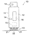
- a robot 10 includes a carriage 13 having an omnidirectional movement mechanism, and the carriage 13 supports an upper portion 12 as an upper body.
- the upper portion 12 includes, for example, a pair of laser range finders 14 and 14 having different mounting heights.
- a stereo camera, a spatial encoding light source, and a stereoscopic device such as a camera may be provided.
- the robot 10 acquires and outputs distance information between the robot and the obstacle for each predetermined azimuth at several height positions.
- the robot 10 may be equipped with a GPS (not shown) to recognize the current position and orientation, or distance information to the passage wall detected by the laser range finder 14 or a stereoscopic device, etc., and an environmental map prepared in advance. Accordingly, the current position and orientation can be recognized.
- the upper part 12 includes a control unit 15 and a work arm 16. The upper portion 12 may be rotated about the vertical axis with respect to the carriage 13.
- the omnidirectional movement mechanism of the carriage 13 includes four omnidirectional wheels 21 arranged side by side at intervals of 90 ° in the circumferential direction, and four motors 22 that drive the omnidirectional wheels 21.
- the carriage 13 may have a configuration in which three or six sets of omnidirectional wheels 21 and a motor 22 are provided.
- Reference numeral 23 denotes a wheel drive unit.
- the wheel drive unit 23 includes a support frame 24 and a motor 22 fixed to the support frame 24, and the support frame 24 is fixed to the carriage 13 by a bracket 25.
- the carriage 13 can freely move in the XY directions and can freely rotate about the vertical axis.
- the type of the omnidirectional movement mechanism is arbitrary, but in the embodiment, it is required that the turning radius is almost zero and that translation and rotation can be performed in any direction. Hereinafter, the omnidirectional movement mechanism will be described. *
- the motor 22 includes a housing 26, and the output shaft 27 of the motor 22 projects outward from the support frame 24 to rotate the omnidirectional wheel 21.
- the omnidirectional wheel 21 is arranged such that the angle formed by the rotation axis (axle) with respect to the front surface 11 of the robot 10 is 45 ° or 135 °.
- the robot 10 has a substantially rectangular shape in which the width W in the front 11 direction is larger than the depth L in plan view. *
- the omnidirectional wheel 21 includes a drive wheel 31 driven by the output shaft 27 of the motor 22 and a plurality of free rollers 32 arranged in an annular shape along the outer periphery of the drive wheel 31.
- the outer peripheral surface of one of the free rollers 32 is always in contact with the floor surface, and the rotation axis of the free roller 32 is perpendicular to the rotation axis of the drive wheel.
- the motor 22 rotates the driving wheel, the driving force is transmitted to the floor surface by the free roller 32.
- the free roller 32 can freely rotate around the rotation axis, the omnidirectional wheel 21 can also move in a direction parallel to the rotation axis of the drive wheel.
- a metal ball or the like may be used. *
- FIG. 3 shows the movement control unit 15 of the embodiment.
- Reference numeral 34 denotes a main control, which includes a CPU, a ROM, a RAM and the like.
- Reference numeral 35 denotes an input unit, and the operator inputs the target position of the robot 10 from the input unit 35, various parameters of an anisotropic model (capsule frame model) described later, the maximum / minimum translation speed of the robot 10, and the maximum / minimum angular speed of the robot 10. Enter.
- a map storage unit 36 stores an environment map of an environment in which the robot 10 can move.
- a route creation unit 37 creates a travel route to the destination with reference to the environment map.
- a motion controller 40 generates a control command related to translation and a control command related to rotation, and outputs these control commands as speed commands (each speed command) to each motor 22 in FIG.
- FIG. 4 is a conceptual block diagram of the motion controller 40.
- a sensor such as the laser range finder 14
- the current position of the player and the azimuth angle to which the front of the aircraft is directed is directed.
- obstacles around the aircraft Moving obstacles such as desks or cabinets and moving obstacles such as people (hereinafter collectively referred to as temporary obstacles), excluding existing obstacles such as walls and pillars, are generally not described in the environment map. From the side, the position of the temporary obstacle in the moving environment such as the passage can be recognized only after the distance information from the sensor is input.
- An information processing unit 41 includes an environmental information processing unit 42 related to obstacles and destinations, and an own device information processing unit 43 related to the own device state such as the current position, orientation, and speed of the own device.
- the unit 43 generates and stores a capsule frame model to be described later from the input parameters.
- the capsule frame model can be defined by three parameters Ca, CR, and CL as described later, these parameters are stored or the capsule frame model itself is stored.
- a set consisting of a plurality of parameters corresponding to the height position is used.
- a plurality of sets are stored, and a plurality of capsule frame models are output and stored.
- the shape of the upper body of the autonomous mobile body is different from that of the carriage or leg, the above-mentioned parameters are changed according to the height position, and the capsule frame model for the upper body is changed.
- a translation control unit 44 and a rotation control unit 45 are arranged in parallel at the subsequent stage of the information processing unit 41, and the control amounts from these are integrated by the drive command generation unit 48 to each motor 22. This is the speed control amount.
- the translation control unit 44 and the rotation control unit 45 depend on the potential membership function (PMF) for the translation control according to the position and size of the obstacle in the information processing unit 41, the destination, the current position and orientation of the own aircraft, and the like. ) And a potential membership function (PMF) related to rotation control.
- the PMF is generated for each obstacle and destination, and these are combined by the fuzzy processing units 46 and 47.
- the fuzzy processing unit 46 determines the direction of translation and the translation speed, and the fuzzy processing unit 47 determines how much the posture of the carriage 13 is changed, that is, the direction of rotation. Determine the angular velocity. These determine the translation direction and translation speed of the carriage, the direction to rotate, and the angular velocity, which are converted by the drive command generation unit 48 as control amounts for the four motors.
- the shape of the robot is generally not uniform along the height depending on its design and function. Furthermore, the shape of the robot changes with time when the arm protrudes from the upper part, the upper part of the robot twists the body with respect to the carriage, or the arm extends and contracts. Also, the obstacles are not always uniform along the height direction. Therefore, a plurality of potential membership functions (PMFs) are preferably prepared along the height position.
- PMFs potential membership functions
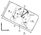
- the capsule frame 50 is formed by connecting the ends of a pair of line segments that are arranged in parallel at a distance of 2Ca facing each other at both ends by a semicircle having a radius Ca.
- PL and PR are the centers of the semicircles
- Po is the center of the carriage
- CL and CR are the distances from the center of the carriage to the points PL and PR.
- Ca is slightly larger than 1 ⁇ 2 of the depth of the robot, but may increase from the normal value due to expansion / contraction of the arm, traction of the wagon, and the like.
- the obstacle O (its center being O0) is approximated by a circle that completely encloses it, and its radius is ro.
- ds is a safe distance, and is a parameter to be introduced for maintaining the distance between the robot 10 and the obstacle and ensuring safety.
- ⁇ ro in FIG. 5 is the direction of the obstacle relative to the front of the carriage when the obstacle is viewed from the center of the carriage.
- ⁇ L is an angle formed by a line segment passing through the center P0 parallel to the line segment connecting PL and O0 and a line segment connecting P0 and O0.
- ⁇ R is an angle formed by a line segment connecting the center P0 parallel to the line segment connecting PR and O0 and a line segment connecting P0 and O0.
- ⁇ L ′ is a line parallel to the line connecting PL and O0 and passing through the center P0, and a line passing through the center P0 parallel to the line connecting both the arc centered on PL and the obstacle safety circle. The angle between the minutes.
- ⁇ R ′ is a line parallel to the line connecting PR and O0 and passing through the center P0, and a line passing through the center P0 parallel to the line connecting the arc centered on PR and the obstacle safety circle.
- the angle between the minutes. Further, ⁇ out in FIG. 6 is the azimuth of translation of the carriage from the front direction of the carriage.
- the capsule frame 50 will be described. As shown in FIG. 6, the capsule frame 50 is a figure that completely encloses the robot 13, has arcs at both ends, and connects arcs with arcs by line segments.
- the capsule frame 50 has a major axis and a minor axis, and corresponds to an area occupied by an anisotropic robot in plan view.
- the longitudinal direction of the robot is represented by a line segment, and the movement of the robot is expressed by the movement of the line segment.
- the reason why the ends of the line segment are connected by a semicircle is to leave a degree of freedom of rotation at any position where the robot can enter.
- FIG. 7 shows an algorithm for translation control.
- step 1 the distance to the obstacle is measured for each azimuth angle.
- the surface of the obstacle that can be seen from the robot 13 can be approximated to a circle, a wall, a cube, or the like.
- the safety distance ds is determined as shown in FIG. 5, and in the case of a wall, the safety distance ds is determined only on the front surface of the wall.
- a safe distance ds is set parallel to the side, and the periphery of the vertex is approximated by an arc of radius ds.
- a potential membership function (PMF) for an obstacle is created based on the distance from the aircraft to the obstacle and the orientation of the aircraft with respect to the obstacle.
- a PMF for the goal is created based on the distance and direction from the aircraft to the destination (goal).
- the goal here is a concept that includes not only the destination that the robot 13 should finally reach, but also the waypoint (subgoal) that the robot 13 should pass through.
- Step 4 the PMF for the obstacle and the PMF for the goal are combined, and when there are a plurality of obstacles, all the PMFs for the plurality of obstacles and the PMF for the goal are combined.
- the lower PMF value is adopted for each azimuth angle.
- a high translational potential means a stable state with a small repulsive force, and the robot translates in a direction where the PMF is maximum.
- the speed of the robot is limited by the PMF and takes a speed between the maximum speed and the minimum speed, and the higher the PMF, the higher the speed.
- the robot determines the direction of translation so as to avoid the obstacle, and decelerates near the obstacle (step 5).
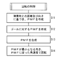
- FIG. 8 shows the rotation control.
- steps 1 and 2 of FIG. 7 information on the distance to the obstacle and the direction of the aircraft with respect to the obstacle has already been acquired. Similar to step 3 in FIG. 7, in step 11 in FIG. 8, a PMF relating to rotation is created based on the distance from the own device to the obstacle for each azimuth and the direction (front direction) of the own device.
- the PMF related to rotation represents how the repulsive force (potential value) from an obstacle changes depending on the direction the robot faces.
- step 12 if a PMF for the goal is created, for example, it is preferable that the robot arrives at the goal facing the front, the PMF is the lowest in the direction in which the goal is the front of the robot, and increases as it deviates.
- step 13 the PMF for the obstacle and the PMF for the goal are combined, and when there are a plurality of obstacles, all the PMFs for the plurality of obstacles and the PMF for the goal are combined. Then, it rotates at an angular velocity according to the PMF in the direction in which the PMF is minimized (step 14).
- FIG. 9 shows the processing of height, which is processing when the surface of the obstacle is not uniform along the height direction or the surface of the robot is not uniform along the height direction.
- laser range finders 14 are provided at a plurality of heights, thereby generating a PMF for each height (step 21). Then, for example, in the same manner as the PMF synthesis in FIGS. 7 and 8, the PMFs are synthesized for each height to be a single PMF, or a plurality of PMFs corresponding to the height positions are left.
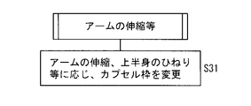
- Fig. 10 shows the process of effects such as expansion and contraction of the arm.
- the capsule frame model to be applied is changed accordingly.
- the capsule frame model can be changed by changing the parameters Ca, CR, and CL. Since the PMF is generated in real time each time, the PMF may be generated based on the new capsule frame model. 9 and 10, even when the posture of the robot changes, the surface of the robot is not uniform along the height direction, and obstacles are not uniform along the height direction, efficient avoidance is possible. Can do. Further, when the robot pulls the wagon, it is preferable to change the parameters Ca, CR, and CL by changing the directions of the long axis and the short axis as viewed from the front of the robot, for example.
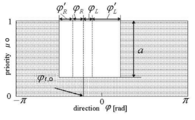
- FIG. 11 to 13 show an example of the PMF relating to translation in the positional relationship between the obstacle and the robot 13 shown in FIG.
- FIG. 11 shows a PMF for an obstacle
- the vertical axis shows preference as a translation direction
- the horizontal axis shows the azimuth angle of translation
- the robot moves forward with an azimuth angle of 0.
- a is a parameter that takes a value between 0 and 1.
- a is 0.
- the influence of an obstacle increases, a approaches 1 and the valley in the center of FIG. Become.
- the valley is vertical, but it may be a smoother valley.
- the variable a is defined as in the equation (1).
- D Ca + ro + ds (2)
- the priority ⁇ o on the vertical axis is 1 at a position not affected by an obstacle, and the affected azimuth angle is decreased by a at a position affected by the obstacle.
- the robot is affected by the obstacle in the central valley, and the robot moves forward in the outer area.
- FIG. 12 shows the PMF for the goal, and when it is far enough from the goal, the value of the PMF is fixed to 1, which indicates that there is no influence of the goal.
- the priority becomes ga, for example, a maximum value of 1 at a preferred direction ⁇ rg, and becomes a small value gb in an unfavorable direction.
- the PMF shown in FIG. 13 is obtained.
- the direction in which the PMF is the maximum is the direction that is convenient for the robot, and the translation speed is determined by the priority at that azimuth. That is, when the priority is high, the permitted speed is large, and when the priority is low, the speed is small. In the case of FIG. 13, it translates at a speed almost equal to the maximum speed at the azimuth angle of ⁇ out.
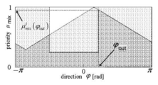
- FIG. 14 shows the PMF with respect to rotation.
- the PMF proceeds in the direction of the highest PMF, but in the rotation, the direction is such that the PMF becomes the lowest.
- .mu.o r which is the PMF after combining about obstacles.
- [mu] e r represents whether effects of which direction the obstacle when viewed from the ship increases, [mu] e r is generated based on the distance information obtained from the distance measuring sensor such as an ultrasonic sensor or a laser rangefinder, a robot center Is a value obtained by dividing the distance from the distance to the obstacle in all directions by the maximum distance used for measurement by the distance measuring sensor.
- ⁇ CR indicates which direction is likely to be affected by obstacles.
- the PMF for the goal is ⁇ g r .
- a control amount for translation (direction and speed to be translated) and a control amount for rotation (direction of rotation and angular velocity) are synthesized to obtain a control amount for the motor.
- the absolute value of velocity is vout
- the direction is ⁇ out
- the angular velocity is ⁇ .
- v 1 ⁇ cos ⁇ ⁇ v r x + sin ⁇ ⁇ v r y + R ⁇ ⁇ (3)
- v 2 ⁇ cos ⁇ ⁇ v r x- sin ⁇ ⁇ v r y- R ⁇ ⁇ (4)
- v 3 ⁇ ⁇ cos ⁇ ⁇ v r x ⁇ sin ⁇ ⁇ v r y + R ⁇ ⁇ (5)
- v 4 ⁇ ⁇ cos ⁇ ⁇ v r x + sin ⁇ ⁇ v r y ⁇ R ⁇ ⁇ (6)
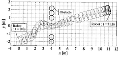
- FIGS. 15 to 19 show simulation results for the robot 10, and the task is to reach the destination through the gap between the obstacles.
- vmax and vmin were 0.5 m / s and 0.0 m / s, respectively, and ⁇ max and ⁇ min were 1.0 rad / s and 0.0 rad / s, respectively.
- an obstacle having a radius of 0.3 m is represented by a point (4.0 m, -2.0 m), a point (4.0 m, -1.4 m), a point (4.0 m, 1.0 m), and a point (4.0. 0m, 1.6m) and points (4.0m, 2.2m) as shown in FIG.
- the point (0.0m, -2.0m) was set as the starting point and moved to the point (11.0m, 2.0m).
- the trajectory in the conventional method (FIG. 17) for avoiding obstacles assuming that the robot is a circle with a radius of 0.6 m is compared with the trajectory of the robot in the embodiment (FIG. 15).
- the robot position was plotted every 1 second. Assuming the robot is one circle and avoiding it, as shown in Fig. 17, it passes between the point (4.0m, -1.4m) and the point (4.0m, 1.0m). It was not possible to reach the target position by avoiding it.
- the azimuth angle was changed in real time, the distance between the obstacles was maintained, the obstacles were passed, and the target position was reached.
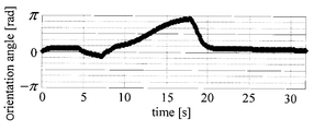
- FIG. 16 shows a history of the posture angle of the robot of the embodiment (azimuth angle from the x direction in front of the robot).
- FIG. 18 shows a history of posture angles at that time.
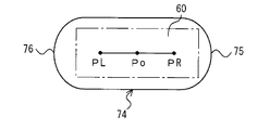
- a capsule frame 62 is provided for the autonomous mobile robot 60, arcs 63 and 64 are provided at both ends in the long axis direction of the robot 60, and centers PR and PL are at the left and right ends of the robot 60.
- the right side of the autonomous mobile robot 70 in FIG. 21 is larger than the left side, and the capsule frame 72 is deformed accordingly, and the radius of the right arc is larger than the radius of the left arc.
- the centers of the arcs 75 and 76 are inside the robot 60. These are all capsule frames.
- the robot is not approximated by a circle or the like, but is treated as having an anisotropy having a major axis and a minor axis.
- a potential for each azimuth angle is generated. Since there is a degree of freedom of rotation in addition to translation, a potential is generated for each of translation and rotation.
- Obstacles can be avoided by generating translational and rotational control amounts based on each potential and driving the moving mechanism based on these. For example, if the robot is stuck in any direction, the robot stops or decelerates and rotates during this time to avoid obstacles. Therefore, obstacles can be smoothly avoided through small gaps.
- the potential membership function in the fuzzy potential method can be generated relatively easily and is suitable for real-time processing.
- the control amount generator determines the translation speed between the predetermined maximum translation speed and the predetermined minimum translation speed based on the value of the potential membership function, and determines the predetermined maximum angular speed and the predetermined minimum angular speed. Determine the angular velocity between. For this reason, the translation speed and the angular velocity can be easily determined, and the robot decelerates carefully and avoids the obstacle so as to avoid interference with the obstacle.
- the capsule frame model can maintain both freedom of rotation and translation at an arbitrary position, and therefore it is easy to avoid obstacles while changing the posture of the robot. 10) Even if the surface of the robot is not uniform along the height direction and the surface of the obstacle changes along the height direction, it is possible to cope with the synthesis of potential membership functions for each height. 11) Even if the shape of the robot changes due to the loaded luggage protruding, the arm extending or contracting, or the robot tilting the upper body, it can be handled by changing the capsule frame model.
- the autonomous mobile robot 10 is taken as an example, but the present invention can also be implemented in an automated guided vehicle equipped with a slide fork, a SCARA arm, a turntable and the like on the ground.
- robots that move by wheels robots that have a total of three or more degrees of freedom of translation and rotation in two directions, such as walking robots, machine tools, and transfer devices, can be similarly implemented.
Abstract
Description
水平面内での並進と鉛直軸回りの回転とが自在な移動機構を備えた台車と、
方位角毎に障害物までの距離を求める障害物センサと、
障害物との干渉を回避するための、移動体の並進に関するポテンシャル及び移動体の回転に関するポテンシャルを、方位角毎の障害物までの距離に基づいて生成するためのポテンシャル生成部と、
生成したポテンシャルに基づき、移動体の並進方向と並進速度及び、回転の方向と角速度とに関する制御量を生成する制御量生成部と、
生成した制御量を合成し移動機構を駆動する駆動部、とを備えることを特徴とする。 The autonomous mobile body of the present invention is an autonomous mobile body having a long axis and a short axis in plan view, which moves to a target position while avoiding an obstacle,
A carriage equipped with a moving mechanism that can freely translate in a horizontal plane and rotate around a vertical axis;
An obstacle sensor that determines the distance to the obstacle for each azimuth,
A potential generation unit for generating a potential related to translation of the moving body and a potential related to rotation of the moving body based on the distance to the obstacle for each azimuth, in order to avoid interference with the obstacle;
Based on the generated potential, a control amount generation unit that generates control amounts related to the translation direction and translation speed of the moving body, and the direction and angular velocity of rotation,
And a drive unit that combines the generated control amounts and drives the moving mechanism.
移動体は、水平面内での並進と鉛直軸回りの回転とが自在な移動機構を備えると共に、
移動体は、障害物センサにより方位角毎に障害物までの距離を求め、障害物との干渉を回避するための、移動体の並進に関するポテンシャル及び移動体の回転に関するポテンシャルを、方位角毎の障害物までの距離に基づいて生成し、生成したポテンシャルに基づき、移動体の並進方向と並進速度及び、回転の方向と角速度とに関する制御量を生成し、生成した制御量を合成し移動機構を駆動することを特徴とする。 The method for controlling an autonomous mobile body according to the present invention is a method for moving and controlling an autonomous mobile body that moves to a target position while avoiding an obstacle and has a long axis and a short axis in a plan view,
The moving body includes a moving mechanism that can freely translate in a horizontal plane and rotate around a vertical axis.
The moving body obtains the distance to the obstacle for each azimuth by the obstacle sensor, and calculates the potential for translation of the moving body and the potential for rotation of the moving body for each azimuth to avoid interference with the obstacle. Generated based on the distance to the obstacle, based on the generated potential, generate the control amount for the translation direction and translation speed of the moving body and the direction of rotation and angular velocity, and synthesize the generated control amount to It is characterized by being driven.
・ 複数の基本行動、例えば並進、回転等の行動をポテンシャルメンバーシップ関数(PMF)を用いて各々表現し、
・ これらのメンバーシップ関数をファジィ演算を用いて統合することにより、各基本行動を考慮した速度ベクトル(速度指令)を決定する。 Preferably, each potential is a potential membership function in the fuzzy potential method, the translational potential membership function represents the degree of interference with the obstacle for each translational azimuth, and the rotational potential membership function is Describes the degree of interference with obstacles for each azimuth. In the fuzzy potential method,
・ Express multiple basic actions such as translation, rotation, etc. using the potential membership function (PMF).
・ By integrating these membership functions using fuzzy operations, a velocity vector (speed command) considering each basic action is determined.
a=(α-||rr,o||)/(α-D) if ||rr,o||<α (1)
D=Ca+ro+ds (2)
以上のように、障害物の影響を受けない位置で、縦軸の優先度μoは1で、障害物の影響を受ける位置では、影響を受ける方位角についてaだけ低下する。図11では中央の谷で、ロボットは障害物の影響を受け、その外側のエリアでロボットは前進する。 11 to 13 show an example of the PMF relating to translation in the positional relationship between the obstacle and the
a = (α− || r r, o ||) / (α−D) if || r r, o || <α (1)
D = Ca + ro + ds (2)
As described above, the priority μo on the vertical axis is 1 at a position not affected by an obstacle, and the affected azimuth angle is decreased by a at a position affected by the obstacle. In FIG. 11, the robot is affected by the obstacle in the central valley, and the robot moves forward in the outer area.
v1 ω= cosδ・vr x+sinδ・vr y+R・ω (3)
v2 ω= cosδ・vr x-sinδ・vr y-R・ω (4)
v3 ω=-cosδ・vr x-sinδ・vr y+R・ω (5)
v4 ω=-cosδ・vr x+sinδ・vr y-R・ω (6) When the constants R and δ are determined as shown in FIG. 6, the target speeds (control amounts) v 1 ω , v 2 ω , v 3 ω , and v 4 ω of the four drive wheels are expressed by equations (3) to (6). Given.
v 1 ω = cos δ · v r x + sin δ · v r y + R · ω (3)
v 2 ω = cos δ · v r x- sin δ · v r y- R · ω (4)
v 3 ω = −cosδ · v r x −sin δ · v r y + R · ω (5)
v 4 ω = −cos δ · v r x + sin δ · v r y −R · ω (6)
1) ロボットを円等で近似せず、長軸と短軸とを備えた異方性のあるものとして扱う。そして障害物との関係について、方位角毎のポテンシャルを生成し、並進の他に回転の自由度があるので、並進と回転の各々に付いてポテンシャルを生成する。各ポテンシャルに基づいて、並進と回転の制御量を発生させ、これらに基づいて移動機構を駆動すると、障害物を回避できる。例えばどの方向に並進しても行き詰まる場合、ロボットは停止あるいは減速等を行い、この間に回転して障害物を回避する。従って小さな隙間を通過して障害物を円滑に回避できる。
2) ファジィポテンシャル法でのポテンシャルメンバーシップファンクションは、比較的簡単に生成でき、リアルタイムでの処理に適している。
3) 制御量生成部は、ポテンシャルメンバーシップファンクションの値に基づいて、所定の最高並進速度と所定の最低並進速度との間で並進速度を決定すると共に、所定の最高角速度と所定の最低角速度との間で角速度を決定する。このため、並進速度と角速度を簡単に決定でき、しかも障害物との干渉を避けるように、ロボットは減速して慎重に障害物を回避する。 In the embodiment, the following effects can be obtained.
1) The robot is not approximated by a circle or the like, but is treated as having an anisotropy having a major axis and a minor axis. As for the relationship with the obstacle, a potential for each azimuth angle is generated. Since there is a degree of freedom of rotation in addition to translation, a potential is generated for each of translation and rotation. Obstacles can be avoided by generating translational and rotational control amounts based on each potential and driving the moving mechanism based on these. For example, if the robot is stuck in any direction, the robot stops or decelerates and rotates during this time to avoid obstacles. Therefore, obstacles can be smoothly avoided through small gaps.
2) The potential membership function in the fuzzy potential method can be generated relatively easily and is suitable for real-time processing.
3) The control amount generator determines the translation speed between the predetermined maximum translation speed and the predetermined minimum translation speed based on the value of the potential membership function, and determines the predetermined maximum angular speed and the predetermined minimum angular speed. Determine the angular velocity between. For this reason, the translation speed and the angular velocity can be easily determined, and the robot decelerates carefully and avoids the obstacle so as to avoid interference with the obstacle.
5) 複数のポテンシャルメンバーシップファンクションの値の最高値もしくは最小値を、方位角毎に求めることにより、簡単にポテンシャルメンバーシップファンクションを合成できる。
6) 並進と回転の相互作用を無視して、簡単に各々の制御量を発生する。すると並進が困難な場合、ロボットは減速ないし停止し、回転して脱出する。回転が不要な場合、並進のみを行う。このため、並進と回転とで協調動作を行っているのに等しい運動ができる。
7) 並進に関する制御量と回転に関する制御量とを加算し、制御量を合成する。このため簡単に移動機構を駆動できる。
8) 実施例の台車は、旋回半径0で任意の方向へ並進と回転とができる。 4) Generate a translational and rotational potential membership function for each of a plurality of obstacles, and generate a potential membership function for guiding the autonomous robot to the destination, and synthesize them. Accordingly, avoidance of interference with a plurality of obstacles and guidance to the destination can be processed by one potential membership function for each translation and rotation.
5) By finding the maximum or minimum value of multiple potential membership functions for each azimuth, the potential membership function can be easily synthesized.
6) Ignore the interaction between translation and rotation, and easily generate each controlled variable. Then, when translation is difficult, the robot decelerates or stops and rotates to escape. If rotation is not required, only translation is performed. For this reason, it is possible to perform the same movement as in the case of performing a cooperative operation by translation and rotation.
7) Add the control amount related to translation and the control amount related to rotation to synthesize the control amount. For this reason, the moving mechanism can be driven easily.
8) The cart of the embodiment can translate and rotate in any direction with a turning radius of 0.
10) 高さ方向に沿ってロボットの表面が一様でなく、また障害物の表面が高さ方向に沿って変化しても、高さ毎のポテンシャルメンバーシップファンクションの合成で対応できる。
11) 搭載した荷物がはみ出した、アームを伸縮した、ロボットが上体を傾けたなどにより、ロボットの形状が変化しても、カプセル枠モデルの変更で対応できる。 9) The capsule frame model can maintain both freedom of rotation and translation at an arbitrary position, and therefore it is easy to avoid obstacles while changing the posture of the robot.
10) Even if the surface of the robot is not uniform along the height direction and the surface of the obstacle changes along the height direction, it is possible to cope with the synthesis of potential membership functions for each height.
11) Even if the shape of the robot changes due to the loaded luggage protruding, the arm extending or contracting, or the robot tilting the upper body, it can be handled by changing the capsule frame model.
14 レーザーレンジファインダ 15 移動制御部 16 アーム
21 全方位車輪 22 モータ 23 ホイール駆動ユニット
24 支持フレーム 25 ブラケット 26 ハウジング
27 出力軸 31 駆動車輪 32 フリーローラ 34 主制御
35 通信部 36 マップ記憶部 37 経路作成部
40 モーションコントローラ 41 情報処理部
42 環境情報処理部 43 自機情報処理部 44 並進制御部
45 回転制御部 46,47 ファジィ処理部
48 駆動指令生成部 50 カプセル枠
60,70 自律移動ロボット 62,72,74 カプセル枠
63,64 円弧 65,66 線分 80,82 障害物
PMF ポテンシャルメンバーシップファンクション
W 台車幅 L 台車の奥行き
Ca カプセル枠の幅の1/2
CR 台車中心からカプセル枠の線分右端までの距離
CL 台車中心からカプセル枠の線分左端までの距離
Po 台車中心 PR,PL カプセル枠の線分の端点
ro 障害物半径 ds 相互作用距離 ω 角速度 ψ 方位角
ψro 台車正面に対する障害物の方位 ψout 台車の並進方位角
ψL 端点PLと台車中心Poとからの障害物中心への方位角の差
ψR 端点PRと台車中心Poとからの障害物中心への方位角の差
ψL’ 直角に対するψLの補角 ψR’ 直角に対するψRの補角 DESCRIPTION OF
PMF Potential Membership Function W Bogie Width L Bogie Depth
1/2 of the width of Ca capsule frame
Distance from the center of the carriage to the right end of the line of the capsule frame CL Distance from the center of the carriage to the left end of the line of the capsule frame Po Center of the carriage PR, PL End point of the line of the capsule frame ro Obstacle radius ds Interaction distance ω Angular velocity ψ Azimuth angle ψro Obstacle direction relative to the front of the carriage ψout Dolly translational azimuth angle ψL Difference in azimuth from the end point PL and the trolley center Po to the obstacle center ψR From the end point PR and the trolley center Po to the obstacle center Azimuth angle difference ψL 'complementary angle of ψL to right angle ψR' complementary angle of ψR to right angle
Claims (8)
- 障害物を回避しながら目標位置まで自律的に移動する自律移動体であって、
水平面内での並進と鉛直軸回りの回転とが自在な移動機構を備えた台車と、
方位角毎に障害物までの距離を求める障害物センサと、
障害物との干渉を回避するための、移動体の並進に関するポテンシャル及び移動体の回転に関するポテンシャルを、方位角毎の前記自律移動体から障害物までの距離に基づいて生成するためのポテンシャル生成部と、
生成したポテンシャルに基づき、移動体の並進方向と並進速度及び、回転の方向と角速度とに関する制御量を生成する制御量生成部と、
生成した制御量を合成し前記移動機構を駆動する駆動制御部、とを備えることを特徴とする、自律移動体。 An autonomous mobile body that moves autonomously to a target position while avoiding obstacles,
A carriage equipped with a moving mechanism that can freely translate in a horizontal plane and rotate around a vertical axis;
An obstacle sensor that determines the distance to the obstacle for each azimuth,
A potential generating unit for generating a potential related to translation of a moving body and a potential related to rotation of the moving body based on the distance from the autonomous moving body to the obstacle for each azimuth to avoid interference with the obstacle. When,
Based on the generated potential, a control amount generation unit that generates control amounts related to the translation direction and translation speed of the moving body, and the direction and angular velocity of rotation,
An autonomous mobile body comprising: a drive control unit that combines the generated control amounts and drives the moving mechanism. - 前記各ポテンシャルはファジィポテンシャル法でのポテンシャルメンバーシップファンクションであり、並進のポテンシャルメンバーシップファンクションは並進の方位角毎に障害物との干渉の程度を表し、回転のポテンシャルメンバーシップファンクションは回転の方位角毎に障害物との干渉の程度を表すことを特徴とする、請求項1の自律移動体。 Each potential is a potential membership function in the fuzzy potential method, the translational potential membership function represents the degree of interference with the obstacle for each translational azimuth, and the rotational potential membership function is the rotational azimuth. 2. The autonomous mobile body according to claim 1, wherein the degree of interference with an obstacle is expressed for each.
- 前記制御量生成部は、ポテンシャルメンバーシップファンクションの値に基づいて、最高並進速度と最低並進速度との間で並進速度を決定すると共に、最高角速度と最低角速度との間で角速度を決定することを特徴とする、請求項2の自律移動体。 The control amount generation unit determines a translation speed between the maximum translation speed and the minimum translation speed based on the value of the potential membership function, and determines an angular speed between the maximum angular speed and the minimum angular speed. The autonomous mobile body according to claim 2, wherein the autonomous mobile body is characterized.
- 前記ポテンシャル生成部は、複数の障害物の各々に対して、並進及び回転のポテンシャルメンバーシップファンクションを発生させると共に、目的地へ自律移動体を誘導するための並進及び回転のポテンシャルメンバーシップファンクションを発生させ、さらに障害物各々へのポテンシャルメンバーシップファンクションと目的地へのポテンシャルメンバーシップファンクションとを、並進及び回転に関して各々合成することを特徴とする、請求項2または3の自律移動体。 The potential generator generates a translation and rotation potential membership function for each of a plurality of obstacles, and also generates a translation and rotation potential membership function for guiding the autonomous mobile body to the destination. The autonomous moving body according to claim 2, further comprising combining a potential membership function for each obstacle and a potential membership function for the destination with respect to translation and rotation.
- 前記並進のポテンシャルメンバーシップファンクションの合成は、複数の並進のポテンシャルメンバーシップファンクションを合成した結果から値の最高値もしくは最小値を、方位角毎に求めることであり、
前記回転のポテンシャルメンバーシップファンクションの合成は、複数の回転のポテンシャルメンバーシップファンクションを合成した結果から値の最高値もしくは最小値を、方位角毎に求めることであることを特徴とする、請求項4の自律移動体。 The synthesis of the translational potential membership function is to obtain the maximum or minimum value for each azimuth from the result of synthesizing a plurality of translational potential membership functions.
5. The composition of the rotational potential membership function is to obtain a maximum value or a minimum value for each azimuth from a result of combining a plurality of rotational potential membership functions. Autonomous mobile body. - 前記制御量生成部は、並進に関する制御量と回転に関する制御量を独立に求めることを特徴とする、請求項1~5のいずれかの自律移動体。 The autonomous moving body according to any one of claims 1 to 5, wherein the control amount generation unit obtains a control amount related to translation and a control amount related to rotation independently.
- 前記移動機構は、車軸と平行な方向への回転が自在なローラを外周に備えた駆動輪を3輪以上備え、かつ前記3輪以上の駆動輪には、前記車軸の方向が異なるものが含まれていることを特徴とする、請求項1~6のいずれかの自律移動体。 The moving mechanism includes three or more drive wheels having rollers on the outer periphery that can freely rotate in a direction parallel to the axle, and the three or more drive wheels include those having different axle directions. The autonomous mobile body according to any one of claims 1 to 6, wherein
- 障害物を回避しながら目標位置まで自律的に移動する自律移動体を移動制御する方法であって、
前記移動体は、水平面内での並進と鉛直軸回りの回転とが可能な移動機構を備えると共に、
前記移動体は、障害物センサにより方位角毎に前記自律移動体から障害物までの距離を求め、障害物との干渉を回避するための、移動体の並進に関するポテンシャル及び移動体の回転に関するポテンシャルを、方位角毎の前記自律移動体から障害物までの距離に基づいて生成し、生成したポテンシャルに基づき、移動体の並進方向と並進速度及び、回転の方向と角速度とに関する制御量を生成し、生成した制御量を合成し前記移動機構を駆動することを特徴とする、自律移動体の制御方法。 A method for controlling movement of an autonomous moving body that moves autonomously to a target position while avoiding an obstacle,
The moving body includes a moving mechanism capable of translation in a horizontal plane and rotation around a vertical axis,
The moving body obtains the distance from the autonomous moving body to the obstacle for each azimuth angle by an obstacle sensor, and avoids interference with the obstacle, and the potential for translation of the moving body and the potential for rotation of the moving body Is generated on the basis of the distance from the autonomous mobile body to the obstacle for each azimuth, and based on the generated potential, control amounts relating to the translation direction and translation speed of the mobile body and the direction and angular speed of rotation are generated. A method for controlling an autonomous mobile body, comprising combining generated control amounts and driving the moving mechanism.
Priority Applications (3)
| Application Number | Priority Date | Filing Date | Title |
|---|---|---|---|
| EP10831490.7A EP2503424A4 (en) | 2009-11-20 | 2010-11-10 | Autonomous mobile body and control method of same |
| KR1020127011636A KR101374616B1 (en) | 2009-11-20 | 2010-11-10 | Autonomous mobile body and control method of same |
| US13/510,396 US8948956B2 (en) | 2009-11-20 | 2010-11-10 | Autonomous mobile body and control method of same |
Applications Claiming Priority (2)
| Application Number | Priority Date | Filing Date | Title |
|---|---|---|---|
| JP2009-264575 | 2009-11-20 | ||
| JP2009264575A JP5398489B2 (en) | 2009-11-20 | 2009-11-20 | Autonomous mobile object and its control method |
Publications (1)
| Publication Number | Publication Date |
|---|---|
| WO2011062095A1 true WO2011062095A1 (en) | 2011-05-26 |
Family
ID=44059574
Family Applications (1)
| Application Number | Title | Priority Date | Filing Date |
|---|---|---|---|
| PCT/JP2010/069985 WO2011062095A1 (en) | 2009-11-20 | 2010-11-10 | Autonomous mobile body and control method of same |
Country Status (5)
| Country | Link |
|---|---|
| US (1) | US8948956B2 (en) |
| EP (1) | EP2503424A4 (en) |
| JP (1) | JP5398489B2 (en) |
| KR (1) | KR101374616B1 (en) |
| WO (1) | WO2011062095A1 (en) |
Cited By (2)
| Publication number | Priority date | Publication date | Assignee | Title |
|---|---|---|---|---|
| CN107562048A (en) * | 2017-08-08 | 2018-01-09 | 浙江工业大学 | Dynamic obstacle avoidance control method based on laser radar |
| CN107885209A (en) * | 2017-11-13 | 2018-04-06 | 浙江工业大学 | A kind of barrier-avoiding method based on dynamic window and virtual target point |
Families Citing this family (29)
| Publication number | Priority date | Publication date | Assignee | Title |
|---|---|---|---|---|
| DE102012206952A1 (en) * | 2012-04-26 | 2013-10-31 | Siemens Aktiengesellschaft | Method and device for controlling the movement of a mobile unit in space |
| DE102013013747A1 (en) * | 2013-08-21 | 2015-02-26 | GM Global Technology Operations, LLC (n.d. Ges. d. Staates Delaware) | Driver assistance system, vehicle with a driver assistance system and method for operating a driver assistance system |
| US9618937B1 (en) | 2014-08-25 | 2017-04-11 | Google Inc. | Slip detection using robotic limbs |
| US10081098B1 (en) | 2014-08-25 | 2018-09-25 | Boston Dynamics, Inc. | Generalized coordinate surrogates for integrated estimation and control |
| US9387588B1 (en) | 2014-08-25 | 2016-07-12 | Google Inc. | Handling gait disturbances with asynchronous timing |
| US9446518B1 (en) * | 2014-11-11 | 2016-09-20 | Google Inc. | Leg collision avoidance in a robotic device |
| US9499218B1 (en) | 2014-12-30 | 2016-11-22 | Google Inc. | Mechanically-timed footsteps for a robotic device |
| US9594377B1 (en) * | 2015-05-12 | 2017-03-14 | Google Inc. | Auto-height swing adjustment |
| CN105094130B (en) * | 2015-07-29 | 2018-01-23 | 广东省自动化研究所 | The AGV transfer robots air navigation aid and device of laser guidance map structuring |
| US10838376B2 (en) * | 2015-09-10 | 2020-11-17 | I.Systems Automação Industrial S.A | Method of generating fuzzy knowledge base for a programmable fuzzy controller |
| US9586316B1 (en) | 2015-09-15 | 2017-03-07 | Google Inc. | Determination of robotic step path |
| US9789919B1 (en) | 2016-03-22 | 2017-10-17 | Google Inc. | Mitigating sensor noise in legged robots |
| EP3512668B1 (en) | 2016-09-14 | 2021-07-21 | iRobot Corporation | Systems and methods for configurable operation of a robot based on area classification |
| WO2018064639A1 (en) | 2016-09-30 | 2018-04-05 | Staples, Inc. | Hybrid modular storage fetching system |
| US10589931B2 (en) | 2016-09-30 | 2020-03-17 | Staples, Inc. | Hybrid modular storage fetching system |
| US10683171B2 (en) | 2016-09-30 | 2020-06-16 | Staples, Inc. | Hybrid modular storage fetching system |
| CN107544506B (en) * | 2017-09-27 | 2021-05-18 | 上海有个机器人有限公司 | Robot following method, robot, and storage medium |
| US11119216B1 (en) * | 2017-11-02 | 2021-09-14 | AI Incorporated | Efficient coverage planning of mobile robotic devices |
| US10705538B2 (en) * | 2018-01-31 | 2020-07-07 | Metal Industries Research & Development Centre | Auto guided vehicle system and operating method thereof |
| CN110162030B (en) * | 2018-02-12 | 2022-11-25 | 北京欣奕华科技有限公司 | Mobile robot and obstacle detection method thereof |
| IL260449B (en) | 2018-07-05 | 2021-04-29 | Israel Aerospace Ind Ltd | Obstacle avoidance in autonomous vehicles |
| US11590997B1 (en) | 2018-08-07 | 2023-02-28 | Staples, Inc. | Autonomous shopping cart |
| US11084410B1 (en) | 2018-08-07 | 2021-08-10 | Staples, Inc. | Automated guided vehicle for transporting shelving units |
| US11630447B1 (en) | 2018-08-10 | 2023-04-18 | Staples, Inc. | Automated guided vehicle for transporting objects |
| CN109333531B (en) * | 2018-10-09 | 2021-01-26 | 深圳前海达闼云端智能科技有限公司 | Method and apparatus for planning speed of mobile device |
| US11180069B2 (en) | 2018-12-31 | 2021-11-23 | Staples, Inc. | Automated loading of delivery vehicles using automated guided vehicles |
| US11119487B2 (en) | 2018-12-31 | 2021-09-14 | Staples, Inc. | Automated preparation of deliveries in delivery vehicles using automated guided vehicles |
| US11124401B1 (en) | 2019-03-31 | 2021-09-21 | Staples, Inc. | Automated loading of delivery vehicles |
| US20220397914A1 (en) * | 2021-06-04 | 2022-12-15 | Ubtech North America Research And Development Center Corp | Fast continuous regulation of nonholonomic mobile robots |
Citations (4)
| Publication number | Priority date | Publication date | Assignee | Title |
|---|---|---|---|---|
| JPH05297937A (en) * | 1992-02-10 | 1993-11-12 | Honda Motor Co Ltd | Obstacle evading route searching method for mobile object |
| JP2006350776A (en) * | 2005-06-17 | 2006-12-28 | Honda Motor Co Ltd | Traveling object route generating device |
| JP2007148595A (en) * | 2005-11-25 | 2007-06-14 | Yaskawa Electric Corp | Moving object |
| JP2009223812A (en) * | 2008-03-18 | 2009-10-01 | Panasonic Electric Works Co Ltd | Autonomous mobile device |
Family Cites Families (30)
| Publication number | Priority date | Publication date | Assignee | Title |
|---|---|---|---|---|
| JP2552279B2 (en) | 1987-02-16 | 1996-11-06 | 富士通株式会社 | Robot attitude control method |
| JPS63220210A (en) * | 1987-03-10 | 1988-09-13 | Canon Inc | Objective lens |
| JPS63229503A (en) * | 1987-03-19 | 1988-09-26 | Fujitsu Ltd | Posture control method for robot |
| US4954962A (en) | 1988-09-06 | 1990-09-04 | Transitions Research Corporation | Visual navigation and obstacle avoidance structured light system |
| US5040116A (en) | 1988-09-06 | 1991-08-13 | Transitions Research Corporation | Visual navigation and obstacle avoidance structured light system |
| US5502638A (en) * | 1992-02-10 | 1996-03-26 | Honda Giken Kogyo Kabushiki Kaisha | System for obstacle avoidance path planning for multiple-degree-of-freedom mechanism |
| JP2761454B2 (en) * | 1993-12-09 | 1998-06-04 | インターナショナル・ビジネス・マシーンズ・コーポレイション | How to guide autonomous mobile machines |
| DE4408982C1 (en) * | 1994-03-16 | 1995-05-18 | Deutsche Forsch Luft Raumfahrt | Autonomous navigation system for mobile robot or manipulator |
| US5835684A (en) * | 1994-11-09 | 1998-11-10 | Amada Company, Ltd. | Method for planning/controlling robot motion |
| US6548982B1 (en) * | 1999-11-19 | 2003-04-15 | Regents Of The University Of Minnesota | Miniature robotic vehicles and methods of controlling same |
| JP2003330542A (en) * | 2002-05-10 | 2003-11-21 | Sanyo Electric Co Ltd | Movement control method of omnidirectional moving vehicle |
| US6904335B2 (en) * | 2002-08-21 | 2005-06-07 | Neal Solomon | System, method and apparatus for organizing groups of self-configurable mobile robotic agents in a multi-robotic system |
| JP2004298977A (en) * | 2003-03-28 | 2004-10-28 | Sony Corp | Action control device, action control method, action control program and mobile robot device |
| JP3841220B2 (en) * | 2004-01-30 | 2006-11-01 | 船井電機株式会社 | Autonomous traveling robot cleaner |
| JP4256812B2 (en) | 2004-04-26 | 2009-04-22 | 三菱重工業株式会社 | Obstacle avoidance method for moving body and moving body |
| JP4285360B2 (en) * | 2004-08-11 | 2009-06-24 | 株式会社安川電機 | Positioning / falling prevention device for moving objects |
| US8670866B2 (en) * | 2005-02-18 | 2014-03-11 | Irobot Corporation | Autonomous surface cleaning robot for wet and dry cleaning |
| JP2006239844A (en) | 2005-03-04 | 2006-09-14 | Sony Corp | Obstacle avoiding device, obstacle avoiding method, obstacle avoiding program and mobile robot device |
| US7587260B2 (en) * | 2006-07-05 | 2009-09-08 | Battelle Energy Alliance, Llc | Autonomous navigation system and method |
| US8355818B2 (en) * | 2009-09-03 | 2013-01-15 | Battelle Energy Alliance, Llc | Robots, systems, and methods for hazard evaluation and visualization |
| US8843244B2 (en) * | 2006-10-06 | 2014-09-23 | Irobot Corporation | Autonomous behaviors for a remove vehicle |
| US8068935B2 (en) * | 2006-10-18 | 2011-11-29 | Yutaka Kanayama | Human-guided mapping method for mobile robot |
| EP1972416B1 (en) * | 2007-03-23 | 2018-04-25 | Honda Research Institute Europe GmbH | Robots with occlusion avoidance functionality |
| JP5080333B2 (en) * | 2007-04-06 | 2012-11-21 | 本田技研工業株式会社 | Object recognition device for autonomous mobile objects |
| JP4490997B2 (en) * | 2007-07-18 | 2010-06-30 | 株式会社東芝 | Mobile robot |
| JP5553373B2 (en) | 2008-03-25 | 2014-07-16 | 株式会社Ihi | Robot apparatus control method and robot apparatus |
| US8515612B2 (en) * | 2008-09-03 | 2013-08-20 | Murata Machinery, Ltd. | Route planning method, route planning device and autonomous mobile device |
| CA2736079A1 (en) * | 2008-09-04 | 2010-03-11 | Iwalk, Inc. | Hybrid terrain-adaptive lower-extremity systems |
| JP4730440B2 (en) * | 2009-01-01 | 2011-07-20 | ソニー株式会社 | Trajectory planning apparatus, trajectory planning method, and computer program |
| US20120167917A1 (en) * | 2011-01-03 | 2012-07-05 | Gilbert Jr Duane L | Autonomous coverage robot |
-
2009
- 2009-11-20 JP JP2009264575A patent/JP5398489B2/en active Active
-
2010
- 2010-11-10 US US13/510,396 patent/US8948956B2/en active Active
- 2010-11-10 WO PCT/JP2010/069985 patent/WO2011062095A1/en active Application Filing
- 2010-11-10 KR KR1020127011636A patent/KR101374616B1/en active IP Right Grant
- 2010-11-10 EP EP10831490.7A patent/EP2503424A4/en not_active Withdrawn
Patent Citations (4)
| Publication number | Priority date | Publication date | Assignee | Title |
|---|---|---|---|---|
| JPH05297937A (en) * | 1992-02-10 | 1993-11-12 | Honda Motor Co Ltd | Obstacle evading route searching method for mobile object |
| JP2006350776A (en) * | 2005-06-17 | 2006-12-28 | Honda Motor Co Ltd | Traveling object route generating device |
| JP2007148595A (en) * | 2005-11-25 | 2007-06-14 | Yaskawa Electric Corp | Moving object |
| JP2009223812A (en) * | 2008-03-18 | 2009-10-01 | Panasonic Electric Works Co Ltd | Autonomous mobile device |
Non-Patent Citations (7)
Cited By (3)
| Publication number | Priority date | Publication date | Assignee | Title |
|---|---|---|---|---|
| CN107562048A (en) * | 2017-08-08 | 2018-01-09 | 浙江工业大学 | Dynamic obstacle avoidance control method based on laser radar |
| CN107562048B (en) * | 2017-08-08 | 2020-10-09 | 浙江工业大学 | Dynamic obstacle avoidance control method based on laser radar |
| CN107885209A (en) * | 2017-11-13 | 2018-04-06 | 浙江工业大学 | A kind of barrier-avoiding method based on dynamic window and virtual target point |
Also Published As
| Publication number | Publication date |
|---|---|
| US20130131910A1 (en) | 2013-05-23 |
| EP2503424A1 (en) | 2012-09-26 |
| US8948956B2 (en) | 2015-02-03 |
| KR20120068959A (en) | 2012-06-27 |
| KR101374616B1 (en) | 2014-03-17 |
| JP2011108130A (en) | 2011-06-02 |
| JP5398489B2 (en) | 2014-01-29 |
| EP2503424A4 (en) | 2016-07-13 |
Similar Documents
| Publication | Publication Date | Title |
|---|---|---|
| JP5398489B2 (en) | Autonomous mobile object and its control method | |
| JP5398488B2 (en) | Autonomous mobile object and its control method | |
| US6289263B1 (en) | Spherical mobile robot | |
| Alonso-Mora et al. | Reciprocal collision avoidance for multiple car-like robots | |
| Oftadeh et al. | A novel time optimal path following controller with bounded velocities for mobile robots with independently steerable wheels | |
| JP2010076630A (en) | Mobile truck | |
| Bjelonic et al. | Autonomous navigation of hexapod robots with vision-based controller adaptation | |
| JP6468127B2 (en) | Omnidirectional moving body, control method and program thereof | |
| Padgett et al. | Vector-based robot obstacle avoidance using LIDAR and mecanum drive | |
| Al-Shanoon et al. | Mobile robot regulation with position based visual servoing | |
| Kumagai et al. | Achievement of recognition guided teleoperation driving system for humanoid robots with vehicle path estimation | |
| CN111506054A (en) | Automatic guiding method for chassis of 4WID-4WIS robot | |
| Kjærgaard et al. | Generic trajectory representation and trajectory following for wheeled robots | |
| Massoud et al. | Mechatronic Design and Path planning optimization for an Omni wheeled mobile robot for indoor applications | |
| Jang et al. | Collision avoidance of a mobile robot for moving obstacles based on impedance force control algorithm | |
| McNinch et al. | Application of a coordinated trajectory planning and real-time obstacle avoidance algorithm | |
| Fares et al. | Omnidirectional platform for autonomous mobile industrial robot | |
| Sakti et al. | Path planning and path following using arrival time field for nonholonomic mobile robot | |
| Hess et al. | Mobilerobot: Control of a redundant kinematic using drive-steering modules for mobile manipulation | |
| Wang et al. | Visual servo control and parameter calibration for mobile multi-robot cooperative assembly tasks | |
| Hirakoso et al. | Online Tracking Control of Autonomous Mobile Robot Utilizing Optimal Formulation | |
| Malheiro et al. | Object transportation by a human and a mobile manipulator: a dynamical systems approach | |
| JP6969278B2 (en) | Autonomous mobile | |
| Brown et al. | Development of Kinematic and Dynamic Model of an Omnidirectional Four Mecanum Wheeled Robot | |
| Selvaraj et al. | Kinematic models of mobile robots: Types and simulation |
Legal Events
| Date | Code | Title | Description |
|---|---|---|---|
| 121 | Ep: the epo has been informed by wipo that ep was designated in this application |
Ref document number: 10831490 Country of ref document: EP Kind code of ref document: A1 |
|
| ENP | Entry into the national phase |
Ref document number: 20127011636 Country of ref document: KR Kind code of ref document: A |
|
| REEP | Request for entry into the european phase |
Ref document number: 2010831490 Country of ref document: EP |
|
| WWE | Wipo information: entry into national phase |
Ref document number: 2010831490 Country of ref document: EP |
|
| NENP | Non-entry into the national phase |
Ref country code: DE |
|
| WWE | Wipo information: entry into national phase |
Ref document number: 13510396 Country of ref document: US |