WO2011044837A1 - 一种激光加工气熔比检测装置和方法 - Google Patents
一种激光加工气熔比检测装置和方法 Download PDFInfo
- Publication number
- WO2011044837A1 WO2011044837A1 PCT/CN2010/077693 CN2010077693W WO2011044837A1 WO 2011044837 A1 WO2011044837 A1 WO 2011044837A1 CN 2010077693 W CN2010077693 W CN 2010077693W WO 2011044837 A1 WO2011044837 A1 WO 2011044837A1
- Authority
- WO
- WIPO (PCT)
- Prior art keywords
- weight
- slit
- main mirror
- gas
- mirror
- Prior art date
- Legal status (The legal status is an assumption and is not a legal conclusion. Google has not performed a legal analysis and makes no representation as to the accuracy of the status listed.)
- Ceased
Links
Images
Classifications
-
- G—PHYSICS
- G02—OPTICS
- G02B—OPTICAL ELEMENTS, SYSTEMS OR APPARATUS
- G02B27/00—Optical systems or apparatus not provided for by any of the groups G02B1/00 - G02B26/00, G02B30/00
- G02B27/50—Optics for phase object visualisation
- G02B27/54—Schlieren-optical systems
-
- G—PHYSICS
- G01—MEASURING; TESTING
- G01N—INVESTIGATING OR ANALYSING MATERIALS BY DETERMINING THEIR CHEMICAL OR PHYSICAL PROPERTIES
- G01N5/00—Analysing materials by weighing, e.g. weighing small particles separated from a gas or liquid
- G01N5/04—Analysing materials by weighing, e.g. weighing small particles separated from a gas or liquid by removing a component, e.g. by evaporation, and weighing the remainder
Definitions
- the invention belongs to the technical field of precision machining, relates to a gas-melt ratio detecting device and method in laser processing, in particular to a research method of laser-material interaction and application thereof in laser processing and forming of thin-plate stitching precision parts .
- High-performance aluminum alloy slot array antenna board for aerospace vehicle radar, missile antenna and ship navigation system with a contour size of 100-600mm and a thickness of only 0.3-0.4mm, which requires processing a number of rectangular slits of different orientations to form a seam.
- Array, slit width is 0.1-0.3mm
- the shape accuracy and dimensional accuracy of the gap are required to be 0.1-1 ⁇ m grade
- the processing surface quality requires Ra ⁇ 1.6 ⁇ m
- microscopic burr and flash for example, stainless steel high-density pore filter plates for fluid purification and purification in petroleum, chemical and other industries have a contour size of 80-200 mm and a plate thickness of 0.5-2 mm, which requires processing a large number of tiny, densely distributed pores and pores.
- the shape is circular, rectangular or even shaped.
- the pore size is 0.1-0.3mm. Due to the limitation of the processing depth-to-diameter ratio, the thickness design is limited. In addition, it is used in the spinning, printing, printing and other industries. Powder and inkjet carbide nozzles with a profile size of 10-100mm, a pore size of 0.1-0.3mm, and a nozzle wall thickness of 0.1-0.3mm. In addition, there is an urgent need to develop high-efficiency, high-quality precision processing methods such as medical microchannel chips and stainless steel microchannel manufacturing molds.
- the above-mentioned thin plate precision structural member is characterized in that the pores and slit shapes of the fine structure are different and complicated, the size is small and dense, and the thin-wall structure; the thin plate having a relatively large outline size and thickness; the dimensional accuracy and shape precision of the part processing and The surface quality is required to be high; the material of the part is a metal material such as a special alloy having a high thermal conductivity.
- the difficulty of processing is that the processing of thin-walled and thin-plate precision parts is easy to be subjected to stress and deformation; in the processing of micro-holes and seams, the cutting performance is limited due to the size of the tool; the traditional processing method is difficult to meet the high precision and high quality of processing. And high efficiency requirements.
- the invention is directed to the processing technical problem of the high-performance aluminum alloy slot array antenna board in the aerospace vehicle radar, the missile antenna and the ship navigation system, and studies the gasification shape when the laser removes the material, collects the vapor flow information, and according to the measurement beam in the gas Refractive index and density relationship in the transport of the compound, identify the refractive index change and distribution characteristics of the vapor flow, quantitatively analyze the gasification morphology of the material removed by laser at different times, calculate the weight of the gasification removal material; combine the precision weighing method, weigh separately After processing, the weight of the test piece and the weight of the melted separation material, and then the weight of the vaporized product and the melted separation material are obtained, and the influence of the laser energy input on the gas-melting ratio of the removed material is studied, and the gas-melting ratio is applied to the laser processing size and precision of the thin plate-stitched component parts. And theoretical and experimental basis for surface quality effects.
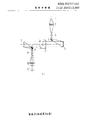
- the detecting device comprises a light source 1, a first optical lens group 2 and a second optical lens group 10, a slit 3, a first turning mirror 4 and a second turning mirror 8, a first main mirror 5 and a second main mirror 7.
- a glass container 6, a research object D, a color knife edge 9, and a high speed recording analyzer 11, the first main mirror 5 and the second main mirror 7 are symmetrically arranged at both ends of the transparent glass container 6, the first optical lens
- the group 2 is located between the light source 1 and the slit 3
- the second optical lens group 10 is located between the color knife edge 9 and the high speed recording analyzer 11, and the first steering mirror 4 is located behind the slit 3, and is capable of detecting the light source 1
- the light is transmitted through the slit 3 to the first main mirror 5, and the second turning mirror 8 is located between the second main mirror 7 and the colored knife edge 9, and the detection light reflected by the second main mirror 7 can be transmitted to the color.
- the light source 1 is a xenon lamp
- the first optical lens group 2 transmits the xenon light to the slit 3
- the detection light passing through the slit 3 is transmitted to the first main mirror 5 through the first turning mirror 4
- a main mirror 5 irradiates the light source 1 with the detection light to the research object in the transparent glass container 6. D; then recording the optical phenomenon that the light source 1 is irradiated to the research object D, and the second main mirror 7 passes the vapor detection signal to the high-speed recording analyzer 11 through the second turning mirror 8 and the color knife edge 9, and analyzes
- the gasification ratio of the gasification in the processing zone is calculated from the state of the gas produced at different times.
- the above laser processing gas ratio detecting device has the following detection methods:
- gasification is generated. Based on the principle of vaporized optical schlieren measurement, the detection light emitted by the light source 1 passes through the flow of vapor when the refractive index changes, and the gas form and density change are identified, according to Glasdstone-Dell.
- the gas equation calculates the gasification density distribution of the material at different times, and then calculates the vapor weight at different times;
- the weight of the test piece before and after the whole laser processing is accurately weighed, and then the molten separation in the transparent glass container 6 is carefully collected, and the weight of the melted separation substance is accurately weighed, and the vaporization and the melting separation are respectively obtained.
- the weight of the material and its gas-melt ratio wherein, for the homogeneous material, the weight of the particles is directly stripped from the substrate, and the ratio of gasification to melting weight is measured by the above method; for the uneven material, the collection is peeled off from the substrate.
- the particles eliminate the effect of removing the particles in a peeling form, and the precision weighing method is also used to obtain the weight of the stripped particles and the total weight of the removed material, thereby correcting the ratio of the precise gasification to the melting weight;
- the layer is subjected to metallographic analysis method to detect the volume of the recast layer based on image processing, and eliminate the influence of the molten recast layer on the weight of the removed material, and obtain a precise gas-melt ratio.
- the invention has the beneficial effects of using the gas-melt ratio detecting device and method to effectively grasp the interaction between laser and material State and condition, through the analysis and regulation of the gasification and melting ratio of the processing zone, to meet the high-quality exclusion requirements of laser processing products, that is, to improve laser precision forming, precision manufacturing precision and quality, is to break through the size and quality indicators of the original processing equipment, An effective way to machine smaller, smaller structures. Produced a variety of material cavities and structural parts, and processed a large number of precision structural parts with a small hole size of 0.05-0.2mm and a depth-to-diameter ratio of 20:1.
- the drawing is a schematic view showing the structure of a laser processing gas ratio detecting device of the present invention.
- the gas-melt ratio detecting device is placed on a laser processing machine as shown in the drawing.
- the laser beam is irradiated from the upper window of the transparent glass container 6 to the research object D in the container, and at the same time, the detection light emitted by the light source 1
- the vapor processing gas is irradiated through the right window of the transparent glass container 6, and the vapor state information is transmitted from the left window of the transparent glass container 6, through the main second mirror 7, the second turning mirror 8, and the color knife edge 9, Finally, it is collected, recorded and analyzed by the high-speed recording analyzer 11;
- the glass container 6 is a transparent and ventilated container, allowing the gas to escape at any time, and the high-speed recording analyzer 11 collects, records and analyzes the vapor state at each moment, accumulating the entire processing.
- the detailed implementation of the process is as follows:
- the laser processing is performed with a 50 gram slit array antenna plate
- the light is irradiated to process the gasification.
- the refractive index changes when the detection light emitted by the light source 1 passes through the flowing vapor, and the gas form and density change are recognized.
- the gasification density distribution of the material at different times is calculated, and then the weight of the vaporization at a time can be calculated to be about 5 grams.
- the precision weighing method is used to accurately calculate the whole laser processing before and after the test.
- the weight of the piece then carefully collect the molten separation in the transparent glass container 6, accurately weigh the weight of the melted separation, respectively obtain the weight of the vaporized and melted separation and its gas-melt ratio, for example, the weighing method is called before and after the entire laser processing
- the difference between the weight of the test piece, that is, the weight of the vaporized product is 5 g.
- the molten separation in the transparent glass container 6 is carefully collected, and the total weight of the molten separated product is 5 g, and the total weight of the laser processing is 10 g, and the gas is calculated.
- the ratio of melting to melting weight is 1; by changing the input of laser energy, the gasification ratio can be controlled, for example, 10 grams of total processing removal, 8 grams is Compound, 2 g of a melt, the melt ratio of the gas 4, obviously, the laser processing gas mass ratio of melt 4, is significantly higher than the melt processing gas mass up to 1 order of magnitude.
- the weight of the particles directly peeled off from the substrate is not used, and the ratio of gasification to melting weight is measured by the above method; for the uneven material, the particles peeled off from the substrate are collected to eliminate the removal by peeling.
- the effect of the particles can obtain the weight of the stripped particles and the total weight of the removed material, thereby correcting the ratio of the precise gasification to the melting weight; for the molten recast layer, the metallographic analysis method is used.
- the sample is subjected to image processing-based re-casting layer volume detection, eliminating the influence of the molten re-casting layer on the weight of the removed material, and obtaining an accurate gas-melt ratio; the method can be used for laser precision cutting, milling, cladding and the like.
- the gas-melt ratio test of the process can be used for laser precision cutting, milling, cladding and the like.
Landscapes
- Physics & Mathematics (AREA)
- General Physics & Mathematics (AREA)
- General Health & Medical Sciences (AREA)
- Chemical & Material Sciences (AREA)
- Analytical Chemistry (AREA)
- Biochemistry (AREA)
- Life Sciences & Earth Sciences (AREA)
- Health & Medical Sciences (AREA)
- Immunology (AREA)
- Pathology (AREA)
- Optics & Photonics (AREA)
- Investigating Or Analysing Materials By Optical Means (AREA)
- Laser Beam Processing (AREA)
Description
一种激光加工气熔比检测装置和方法
技术领域
本发明属于精密加工技术领域,涉及一种激光加工中的气熔比检测装置和方法,特别涉及激光与材料相互作用的研究方法及其在薄板缝阵类精密零部件激光加工与成形中的应用。
背景技术
航空航天飞行器雷达、导弹天线和轮船导航系统中的高性能铝合金缝阵天线板,轮廓尺寸达100-600mm,厚度仅为0.3-0.4mm,其上需要加工许多不同方位矩形窄缝,形成缝阵,缝隙宽度为0.1-0.3mm,缝隙的形状精度和尺寸精度要求达0.1-1µm级,加工表面质量要求Ra<1.6µm,微观无毛刺和飞边。再如,应用于石油、化工等行业的流体净化和提纯的不锈钢高密孔隙过滤板,轮廓尺寸达80-200mm,板厚为0.5-2mm,其上需要加工大量、微小、高密分布的孔隙,孔隙形状为圆形、矩形甚至是异形,孔隙尺寸为0.1-0.3mm,受加工深径比大小的限制,板厚设计受到限制;还有,应用于纺织、轻工、印刷等行业喷丝、喷粉和喷墨的硬质合金喷头,轮廓尺寸为10-100mm,孔隙尺寸0.1-0.3mm,喷头壁厚0.1-0.3mm。此外,急需开发医用微流道芯片及其不锈钢微流道制作模具等高效、高质量精密加工方法。
上述薄板精密结构件特点是,微细结构的孔、缝形状各异而复杂,尺寸细小而密集,薄壁结构;属于一种轮廓尺寸与厚度之比较大的薄板;零件加工尺寸精度、形状精度和表面质量要求高;零件材料为导热率较高的特殊合金等金属材料。其加工难点在于,薄壁、薄板精密零件的加工容易受力、受热变形;微小孔、缝加工中,受工具尺寸的限制,切削性能差;传统加工工艺方法难以满足加工的高精度、高质量和高效率等要求。
在激光精密加工中,气熔比对加工精度和质量有直接影响,因此,研究和开发激光加工气熔比检测装置和方法,具有重要理论意义与应用价值。
发明内容
本发明针对航空航天飞行器雷达、导弹天线和轮船导航系统中的高性能铝合金缝阵天线板的加工技术难题,研究识别激光去除材料时气化物形态,采集气化物流动信息,根据测量光束在气化物传输中折射率与密度关系,识别气化物流动折射率变化与分布特征,定量分析不同时刻激光去除材料的气化形态,计算得到气化去除材料的重量;结合精密称重法,分别称量加工后,试件重量和熔化分离物重量,进而得到气化物与熔化分离物重量,研究激光能量输入对去除材料气熔比的影响,提供气熔比对薄板缝阵类零件激光加工尺寸,精度和表面质量影响的理论与试验依据。
本发明采用的技术方案是:
把检测光源传递至光学透镜组,经过狭缝、转向反射镜和主反射镜,照射置于透明、透气玻璃容器中的研究对象D,当激光加工时,产生加工气化物状态,此状态信号经过主反射镜、转向反射镜和彩色刀口,传至高速记录分析仪,由记录仪分析,得到不同时刻气化状态信息,辅助精密称重法得到气熔比。
检测装置由光源1、第一光学透镜组2和第二光学透镜组10、狭缝3、第一转向反射镜4和第二转向反射镜8、第一主反射镜5和第二主反射镜7、玻璃容器6、研究对象D、彩色刀口9、高速记录分析仪11组成,第一主反射镜5和第二主反射镜7对称的布置于透明玻璃容器6的两端,第一光学透镜组2位于光源1和狭缝3之间,第二光学透镜组10位于彩色刀口9和高速记录分析仪11之间,第一转向反射镜4位于狭缝3之后,能够将光源1发出的检测光通过狭缝3传递到第一主反射镜5,第二转向反射镜8位于第二主反射镜7和彩色刀口9之间,能够将第二主反射镜7反射来的检测光传递给彩色刀口9;其中,光源1为氪灯,第一光学透镜组2把氪灯光传递至狭缝3;通过狭缝3的检测光通过第一转向反射镜4传递到第一主反射镜5;第一主反射镜5把光源1检测光照射到透明玻璃容器6中的研究对象D;接着记录光源1照射到研究对象D产生的光学现象,第二主反射镜7把气化物检测信号,经过第二转向反射镜8和彩色刀口9,传至高速记录分析仪11,经分析不同时刻产生的气化物状态,计算得出加工区气化物气熔比。
上述的激光加工气熔比检测装置,其检测方法是:
首先,激光加工时,产生气化物,基于气化物光学纹影测量原理,光源1发出的检测光穿过流动气化物时折射率变化,识别气化物形态与密度变化,根据格拉斯德通-戴尔气态方程计算出不同时刻材料气化物密度分布,进而计算出不同时刻气化物重量;
其次,采用分辨率较高称重法,精确称得整个激光加工前后试件重量,然后,仔细收集透明玻璃容器6中熔化分离物,精确称得熔化分离物重量,分别得到气化物与熔化分离物重量及其气熔比;其中,对于均质材料不计直接从基体上剥离掉颗粒的重量,采用上述方法,测出气化与熔化重量之比;对于不均匀材质,收集从基体上剥离掉的颗粒,消除以剥离形态去除颗粒的影响,同样采用精密称重法,可得到剥离掉颗粒的重量以及去除材料的总重量,从而修正得到精确的气化与熔化重量之比;对于熔化重铸层,采用金相分析法,对样件进行基于图像处理的重铸层体积检测,消除熔化重铸层对去除材料重量的影响,得到精确的气熔比。
本发明的有益效果:采用气熔比检测装置和方法,有效掌握激光与材料相互作用
状态与条件,通过加工区气化与熔化比例的分析与调控,满足激光加工产物的高质量排除要求,即提高激光精密成形、精密制造精度和质量,是突破原加工设备的尺寸与质量指标,加工出更小尺寸微小结构的有效方法。
制作出用于多种材料型腔和结构零件,加工出大量 微小孔缝尺寸为0.05-0.2mm,其 深径比达到 20 :1的精密结构零件,
解决雷达天线板纺织、石油、化工领域中的过滤结构件的技术难题,满足微结构零部件的图纸技术要求,解决微细塑料模具沟槽型腔的加工难题,包括尺寸、形状、位置精度与质量要求,提高激光加工精度、质量1个数量级。
附图说明
附图是本发明的激光加工气熔比检测装置结构示意图。
图中:1光源;2第一光学透镜组;3狭缝;4第一转向反射镜;5第一主反射镜;6玻璃容器;7第二主反射镜;D研究对象;8第二转向反射镜;9彩色刀口;10第二光学透镜组;11高速记录分析仪。
具体实施方式
结合技术方案和附图详细说明本发明的具体实施方式。
实施例:
把气熔比检测装置置于如附图所示的激光加工机上,当激光加工时,激光束自透明玻璃容器6的上窗口照射到容器内的研究对象D,同时,光源1发出的检测光通过透明玻璃容器6的右窗口,照射激光加工气化物,该气化物状态信息由透明玻璃容器6的左窗口传出,经主第二反射镜7、第二转向反射镜8和彩色刀口9,最终被高速记录分析仪11采集、记录和分析;玻璃容器6为一透明、透气容器,允许气化物随时逸出,高速记录分析仪11采集、记录和分析各个时刻的气化物状态,累计整个加工过程,其详细实施方式如下:
激光加工以50克缝阵天线板时,测量光照射加工气化物,基于气化物光学纹影测量原理,光源1发出的检测光穿过流动气化物时折射率变化,识别气化物形态与密度变化,根据格拉斯德通-戴尔气态方程计算出不同时刻的材料气化物密度分布,进而计算出可个时刻气化物重量约5克;同时,采用精密称重法,精确称得整个激光加工前后试件重量,然后,仔细收集透明玻璃容器6中熔化分离物,精确称得熔化分离物重量,分别得到气化物与熔化分离物重量及其气熔比,例如,称重法称得整个激光加工前后试件重量之差,即气化物重量5克,另一方面,仔细收集透明玻璃容器6内熔化分离物,称得熔化分离物总重量5克,得出激光加工去除总重量10克,算出气化与熔化重量之比为1;通过改变激光能量输入,可控制气化比大小,例如,加工总去除量10克中,8克为气化物、2克为熔化物,则气熔比为4,显然,气熔比为4的激光加工质量,明显高于气熔比为1的加工质量达1个数量级。其中,对于均质材料不计直接从基体上剥离掉颗粒的重量,采用上述方法,测出气化与熔化重量之比;对于不均匀材质,收集从基体上剥离掉的颗粒,消除以剥离形态去除颗粒的影响,同样采用精密称重法,可得到剥离掉颗粒的重量以及去除材料的总重量,从而修正得到精确的气化与熔化重量之比;对于熔化重铸层,采用金相分析法,对样件进行基于图像处理的重铸层体积检测,消除熔化重铸层对去除材料重量的影响,得到精确的气熔比;该方法可以用于激光精密切割、铣削、熔覆等多种加工过程的气熔比检测。
Claims (1)
1
、一种激光加工气熔比检测装置,其特征是:检测装置由光源[1]、第一光学透镜组[2]和第二光学透镜组[10]、狭缝[3]、第一转向反射镜[4]和第二转向反射镜[8]、第一主反射镜[5]和第二主反射镜[7]、玻璃容器[6]、研究对象[D]、彩色刀口[9]、高速记录分析仪[11]组成,第一主反射镜[5]和第二主反射镜[7]对称的布置于透明玻璃容器[6]的两端,第一光学透镜组[2]位于光源[1]和狭缝[3]之间,第二光学透镜组[10]位于彩色刀口[9]和高速记录分析仪[11]之间,第一转向反射镜[4]位于狭缝[3]之后,能够将光源[1]发出的检测光通过狭缝[3]传递到第一主反射镜[5],第二转向反射镜[8]位于第二主反射镜[7]和彩色刀口[9]之间,能够将第二主反射镜[7]反射来的检测光,传递给彩色刀口[9];其中,光源[1]为氪灯,第一光学透镜组[2]把氪灯光传递至狭缝[3];通过狭缝[3]的检测光通过第一转向反射镜[4]传递到第一主反射镜[5];第一主反射镜[5]把光源[1]发出的检测光照射到透明玻璃容器[6]中的研究对象[D];接着记录检测光照射到研究对象[D]产生的光学现象,第二主反射镜[7]把气化物检测信号,经过第二转向反射镜[8]和彩色刀口[9],传至高速记录分析仪[11],经分析不同时刻产生的气化物状态,计算得出加工区气化物气熔比。
2
、权利要求1所述装置的检测方法,其特征是:首先激光加工时,产生气化物,基于气化物光学纹影测量原理,光源[1]发出的检测光穿过流动气化物时折射率变化,识别气化物形态与密度变化,根据格拉斯德通-戴尔气态方程计算出不同时刻材料气化物密度分布,进而计算出不同时刻气化物重量;其次,采用分辨率较高称重法,精确称得整个激光加工前后试件重量,然后,仔细收集玻璃容器[6]中熔化分离物,精确称得熔化分离物重量,分别得到气化物与熔化分离物重量及其气熔比;其中,对于均质材料不计直接从基体上剥离掉颗粒的重量,采用上述方法,测出气化与熔化重量之比;对于不均匀材质,收集从基体上剥离掉的颗粒,消除以剥离形态去除颗粒的影响,同样采用精密称重法,可得到剥离掉颗粒的重量以及去除材料的总重量,从而修正得到精确的气化与熔化重量之比;对于熔化重铸层,采用金相分析法,对样件进行基于图像处理的重铸层体积检测,消除熔化重铸层对去除材料重量的影响,得到精确的气熔比。
Priority Applications (1)
| Application Number | Priority Date | Filing Date | Title |
|---|---|---|---|
| US13/447,314 US8810781B2 (en) | 2009-10-15 | 2012-04-16 | Device and method for measuring vaporization-melt ratio |
Applications Claiming Priority (2)
| Application Number | Priority Date | Filing Date | Title |
|---|---|---|---|
| CN 200910308292 CN101672754B (zh) | 2009-10-15 | 2009-10-15 | 一种激光加工气熔比检测装置和方法 |
| CN200910308292.4 | 2009-10-15 |
Related Child Applications (1)
| Application Number | Title | Priority Date | Filing Date |
|---|---|---|---|
| US13/447,314 Continuation-In-Part US8810781B2 (en) | 2009-10-15 | 2012-04-16 | Device and method for measuring vaporization-melt ratio |
Publications (1)
| Publication Number | Publication Date |
|---|---|
| WO2011044837A1 true WO2011044837A1 (zh) | 2011-04-21 |
Family
ID=42020074
Family Applications (1)
| Application Number | Title | Priority Date | Filing Date |
|---|---|---|---|
| PCT/CN2010/077693 Ceased WO2011044837A1 (zh) | 2009-10-15 | 2010-10-13 | 一种激光加工气熔比检测装置和方法 |
Country Status (3)
| Country | Link |
|---|---|
| US (1) | US8810781B2 (zh) |
| CN (1) | CN101672754B (zh) |
| WO (1) | WO2011044837A1 (zh) |
Families Citing this family (5)
| Publication number | Priority date | Publication date | Assignee | Title |
|---|---|---|---|---|
| CN101672754B (zh) * | 2009-10-15 | 2011-05-04 | 大连理工大学 | 一种激光加工气熔比检测装置和方法 |
| CN110187512B (zh) * | 2019-06-12 | 2023-12-19 | 中国空气动力研究与发展中心高速空气动力研究所 | 可视化调节的抛物面镜彩色纹影成像装置 |
| CN112284683A (zh) * | 2020-11-12 | 2021-01-29 | 华北科技学院 | 预混气体爆燃流场波系演化过程的观测方法及观测系统 |
| CN112775569A (zh) * | 2020-12-24 | 2021-05-11 | 苏州禾弘电子科技有限公司 | 一种电路板的激光钻孔方法 |
| CN116217267A (zh) * | 2023-03-24 | 2023-06-06 | 广东省科学院新材料研究所 | 一种氧化铝陶瓷密排缝阵产品及其零件与制备方法 |
Citations (3)
| Publication number | Priority date | Publication date | Assignee | Title |
|---|---|---|---|---|
| DE10048791A1 (de) * | 2000-10-02 | 2002-04-25 | Deutsch Zentr Luft & Raumfahrt | Farbmaske für eine Farbschlierenapparatur, Farbschlierenapparatur und Farbschlierenverfahren |
| CN1547057A (zh) * | 2003-12-08 | 2004-11-17 | 中国科学技术大学 | 数字式二维彩色纹影光源及流场显示方法 |
| CN101672754A (zh) * | 2009-10-15 | 2010-03-17 | 大连理工大学 | 一种激光加工气熔比检测装置和方法 |
Family Cites Families (7)
| Publication number | Priority date | Publication date | Assignee | Title |
|---|---|---|---|---|
| US2547212A (en) * | 1948-01-17 | 1951-04-03 | Philips Lab Inc | Apparatus for determining the composition of a substance |
| US3600590A (en) * | 1968-11-12 | 1971-08-17 | Harry Einstein | Gas measuring apparatus for detecting contaminants |
| US3995960A (en) * | 1975-07-25 | 1976-12-07 | Nasa | Method and apparatus for background signal reduction in opto-acoustic absorption measurement |
| DE68917856T2 (de) * | 1988-10-31 | 1995-04-06 | Fujikura Ltd | Sauerstoffsensorvorrichtung. |
| US5060508A (en) * | 1990-04-02 | 1991-10-29 | Gaztech Corporation | Gas sample chamber |
| US5747808A (en) * | 1994-02-14 | 1998-05-05 | Engelhard Sensor Technologies | NDIR gas sensor |
| US5936250A (en) * | 1997-07-24 | 1999-08-10 | General Monitors, Incorporated | Ultraviolet toxic gas point detector |
-
2009
- 2009-10-15 CN CN 200910308292 patent/CN101672754B/zh not_active Expired - Fee Related
-
2010
- 2010-10-13 WO PCT/CN2010/077693 patent/WO2011044837A1/zh not_active Ceased
-
2012
- 2012-04-16 US US13/447,314 patent/US8810781B2/en not_active Expired - Fee Related
Patent Citations (3)
| Publication number | Priority date | Publication date | Assignee | Title |
|---|---|---|---|---|
| DE10048791A1 (de) * | 2000-10-02 | 2002-04-25 | Deutsch Zentr Luft & Raumfahrt | Farbmaske für eine Farbschlierenapparatur, Farbschlierenapparatur und Farbschlierenverfahren |
| CN1547057A (zh) * | 2003-12-08 | 2004-11-17 | 中国科学技术大学 | 数字式二维彩色纹影光源及流场显示方法 |
| CN101672754A (zh) * | 2009-10-15 | 2010-03-17 | 大连理工大学 | 一种激光加工气熔比检测装置和方法 |
Non-Patent Citations (1)
| Title |
|---|
| NI: "Gang the visualization of unsteady dynamic vortex.", AERODYNAMIC EXPERIMENT AND MEASUREMENT& CONTROL., vol. 10, no. 3, September 1996 (1996-09-01), pages 59 - 62 * |
Also Published As
| Publication number | Publication date |
|---|---|
| CN101672754A (zh) | 2010-03-17 |
| US8810781B2 (en) | 2014-08-19 |
| CN101672754B (zh) | 2011-05-04 |
| US20120200848A1 (en) | 2012-08-09 |
Similar Documents
| Publication | Publication Date | Title |
|---|---|---|
| WO2011044837A1 (zh) | 一种激光加工气熔比检测装置和方法 | |
| CN109540771B (zh) | 一种精准分选白细胞亚型的声光微流控芯片及其分选方法 | |
| WO2011105679A9 (ko) | 고감도 표면 플라즈몬 공명 센서, 표면 플라즈몬 공명 센서칩, 및 표면 플라즈몬 공명 센서 소자의 제조 방법 | |
| CN108907191A (zh) | 适用于高速风洞试验的30CrMnSiA金属模型增材制造方法 | |
| Liu et al. | Temperature-dependent wetting characteristics of micro–nano-structured metal surface formed by femtosecond laser | |
| EP2074405B1 (en) | Production method of a sensor film | |
| Jha et al. | Micro-patterning in anodic oxide film on aluminium by laser irradiation | |
| Fogel et al. | Mechanical properties of 3D metallic microstructures printed by laser induced forward transfer | |
| CN2773689Y (zh) | 微观流场粒子图像显微测速装置 | |
| CN108152107A (zh) | 一种3d打印仿真模拟用金属材料热收缩参数测量装置 | |
| CN1405554A (zh) | 界面结合强度的远紫外激光划痕测量方法及装置 | |
| Zhang et al. | Label-free highly sensitive probe detection with novel hierarchical SERS substrates fabricated by nanoindentation and chemical reaction methods | |
| CN1928530A (zh) | 光子测量系统及该系统测量聚合物挤出发泡过程的方法 | |
| White et al. | Femtosecond micro-and nano-machining of materials for microfluidic applications | |
| CN113916851B (zh) | 一种基于叶绿素荧光信号的显微分选方法 | |
| CN105158207A (zh) | 一种透明材料上高深径比微孔重铸层的测量装置及方法 | |
| RO135058A0 (ro) | Procedeu de obţinere a unei reţele de nanopiloni poli- merici metalizaţi utilizată ca substrat sers | |
| Singer et al. | Processability Of Soda-Lime Glass In Laser-Based Powder Bed Fusion | |
| CN119238950B (zh) | 基于仿生纤毛的水声传感器一体化集成制造系统及方法 | |
| Buchheim et al. | Advanced experimental techniques and their application to automotive aerodynamics | |
| JP2001241934A (ja) | 異物検出方法及びプリンタへッドの製造方法 | |
| Xie et al. | Laser-induced backside wet/dry etching microstructures on transparent and brittle materials | |
| CN114923877B (zh) | 一种多种气体检测芯片及其制备方法 | |
| CN205673597U (zh) | 具有无损探伤功能的3d打印设备 | |
| Li et al. | Advanced and Extreme Micro-Nano Manufacturing Technologies |
Legal Events
| Date | Code | Title | Description |
|---|---|---|---|
| 121 | Ep: the epo has been informed by wipo that ep was designated in this application |
Ref document number: 10823067 Country of ref document: EP Kind code of ref document: A1 |
|
| NENP | Non-entry into the national phase |
Ref country code: DE |
|
| 122 | Ep: pct application non-entry in european phase |
Ref document number: 10823067 Country of ref document: EP Kind code of ref document: A1 |