WO2011043172A1 - Contrôleur, réseau de contrôleur et procédé de contrôle - Google Patents
Contrôleur, réseau de contrôleur et procédé de contrôle Download PDFInfo
- Publication number
- WO2011043172A1 WO2011043172A1 PCT/JP2010/066010 JP2010066010W WO2011043172A1 WO 2011043172 A1 WO2011043172 A1 WO 2011043172A1 JP 2010066010 W JP2010066010 W JP 2010066010W WO 2011043172 A1 WO2011043172 A1 WO 2011043172A1
- Authority
- WO
- WIPO (PCT)
- Prior art keywords
- priority
- discharge
- charge
- power
- charging
- Prior art date
Links
Images


Classifications
-
- H—ELECTRICITY
- H02—GENERATION; CONVERSION OR DISTRIBUTION OF ELECTRIC POWER
- H02J—CIRCUIT ARRANGEMENTS OR SYSTEMS FOR SUPPLYING OR DISTRIBUTING ELECTRIC POWER; SYSTEMS FOR STORING ELECTRIC ENERGY
- H02J7/00—Circuit arrangements for charging or depolarising batteries or for supplying loads from batteries
- H02J7/0013—Circuit arrangements for charging or depolarising batteries or for supplying loads from batteries acting upon several batteries simultaneously or sequentially
- H02J7/0014—Circuits for equalisation of charge between batteries
- H02J7/0018—Circuits for equalisation of charge between batteries using separate charge circuits
-
- H—ELECTRICITY
- H01—ELECTRIC ELEMENTS
- H01M—PROCESSES OR MEANS, e.g. BATTERIES, FOR THE DIRECT CONVERSION OF CHEMICAL ENERGY INTO ELECTRICAL ENERGY
- H01M10/00—Secondary cells; Manufacture thereof
- H01M10/42—Methods or arrangements for servicing or maintenance of secondary cells or secondary half-cells
- H01M10/44—Methods for charging or discharging
-
- H—ELECTRICITY
- H02—GENERATION; CONVERSION OR DISTRIBUTION OF ELECTRIC POWER
- H02J—CIRCUIT ARRANGEMENTS OR SYSTEMS FOR SUPPLYING OR DISTRIBUTING ELECTRIC POWER; SYSTEMS FOR STORING ELECTRIC ENERGY
- H02J7/00—Circuit arrangements for charging or depolarising batteries or for supplying loads from batteries
- H02J7/0013—Circuit arrangements for charging or depolarising batteries or for supplying loads from batteries acting upon several batteries simultaneously or sequentially
- H02J7/0025—Sequential battery discharge in systems with a plurality of batteries
-
- Y—GENERAL TAGGING OF NEW TECHNOLOGICAL DEVELOPMENTS; GENERAL TAGGING OF CROSS-SECTIONAL TECHNOLOGIES SPANNING OVER SEVERAL SECTIONS OF THE IPC; TECHNICAL SUBJECTS COVERED BY FORMER USPC CROSS-REFERENCE ART COLLECTIONS [XRACs] AND DIGESTS
- Y02—TECHNOLOGIES OR APPLICATIONS FOR MITIGATION OR ADAPTATION AGAINST CLIMATE CHANGE
- Y02E—REDUCTION OF GREENHOUSE GAS [GHG] EMISSIONS, RELATED TO ENERGY GENERATION, TRANSMISSION OR DISTRIBUTION
- Y02E60/00—Enabling technologies; Technologies with a potential or indirect contribution to GHG emissions mitigation
- Y02E60/10—Energy storage using batteries
Definitions
- the present invention relates to a control device that controls charging / discharging of a plurality of secondary batteries, a control device network that includes a plurality of control devices that control charging / discharging of a plurality of charging / discharging units, and a control that controls charging / discharging of a plurality of secondary batteries. Regarding the method.
- Patent Document 1 relates to charge / discharge control of a plurality of secondary batteries.
- a plurality of secondary batteries (secondary battery modules 7a and 7b) are given a charge priority and a discharge priority (paragraph 0090, etc.), and a secondary battery having a high charge priority is changed to a secondary battery having a low charge priority.
- the charging power is assigned in order
- the discharging power is assigned in order from the secondary battery having the highest discharge priority to the lower secondary battery (paragraph 0107)
- the charging / discharging power is adjusted according to the amount correlated with the internal resistance (paragraph 0080). Etc.).
- the SOC discharged state
- the target value of SOC is often set to about 50%.
- the target value of SOC is temporarily set near 100%, and the calculated value of the discharge capacity of the secondary battery is corrected at the end of discharging. When this is done, it is temporarily set near 0%.
- the present invention has been made to solve this problem, and an object of the present invention is to provide a control device, a control device network, and a control method that can easily bring the SOC of a secondary battery close to a target value.
- the 1st invention is a control apparatus which controls charging / discharging of a some secondary battery, Comprising:
- the charging / discharging electric current measurement part which measures each charging / discharging current of several secondary battery, and charging / discharging electric power are command values
- a bi-directional converter that controls charging / discharging of each of the plurality of secondary batteries so that the charging / discharging current measurement values measured by the charging / discharging current measuring unit are integrated to each of the plurality of secondary batteries.
- a discharge capacity calculation unit for calculating a discharge capacity, a charge state calculation unit for calculating the charge state of each of the plurality of secondary batteries from the calculated value of the discharge capacity calculated by the discharge capacity calculation unit, and a first index
- a priority determining unit that reflects and determines the charging priority and discharging priority of each of the plurality of secondary batteries, and from a secondary battery having a high charging priority determined by the priority determining unit to a low secondary battery Charging power is allocated in order and determined by the priority determination unit.
- a power allocation unit that sequentially allocates discharge power from a secondary battery having a high discharge priority to a secondary battery having a low discharge priority, and a charge / discharge commander that instructs the bidirectional converter to charge / discharge the charge / discharge power allocated by the power allocation unit
- the first indicator includes, as a factor, a difference in the target value of the charge state with respect to the calculated value of the charge state calculated by the charge state calculation unit
- the priority determination unit includes the charge state The charging priority is increased and the discharging priority is decreased as the difference between the charging state target value calculated by the calculating unit and the charging state target value increases.
- the control device of the first aspect further includes a temperature sensor that measures the temperature of each of the plurality of secondary batteries, and the plurality of secondary batteries generate secondary reactions that generate an exothermic reaction when discharged.
- the battery is a battery
- the first index includes a measured value of the temperature measured by the temperature sensor as a factor
- the priority determination unit is configured to prioritize discharge as the measured value of the temperature measured by the temperature sensor increases. Decrease the degree.
- the control device further includes a temperature sensor that measures the temperature of each of the plurality of secondary batteries.
- the battery is a battery
- the first index includes a measured value of the temperature measured by the temperature sensor as a factor
- the priority determining unit prioritizes charging as the measured value of the temperature measured by the temperature sensor increases. Decrease the degree.
- the power allocation unit allocates a discharge power equal to or lower than a first upper limit value to each of the plurality of secondary batteries
- the control device includes a plurality of secondary batteries.
- the temperature is an upper limit based on a temperature sensor that measures the temperature of each of the batteries, a measured value of the temperature measured by the temperature sensor for each of the plurality of secondary batteries, and a calculated value of the discharge capacity calculated by the discharge capacity calculating unit.
- An upper limit value calculating unit that calculates a second upper limit value of the discharge power maintained below the temperature, wherein the first index is the second upper limit value calculated by the upper limit value calculating unit.
- a ratio of 1 to the upper limit value is included as a factor, and the priority determination unit increases the discharge priority as the ratio of the second upper limit value calculated by the upper limit value calculation unit to the first upper limit value increases.
- the 5th invention is the control apparatus of any one of the 1st thru
- the first index includes the determination result of the necessity determination unit as a factor, and the priority determination unit needs to correct the calculation value of the discharge capacity at the end of charging by the necessity determination unit. If it is determined that there is, the charging priority is raised and the discharging priority is lowered.
- 6th invention is the control apparatus of any one of the 1st thru
- the first index includes the determination result of the necessity determination unit as a factor, and the priority determination unit needs to correct the calculation value of the discharge capacity at the end of discharge by the necessity determination unit. If it is determined that there is, the charge priority is lowered and the discharge priority is raised.
- an end-of-charge detection for detecting the arrival at the end of charge in which the calculated value of the discharge capacity is corrected for each of the plurality of secondary batteries.
- the first index includes a detection result of the end-of-charge detection unit as a factor, and the priority determination unit is charged when reaching the end of charge is detected by the end-of-charge detection unit. Lower priority and increase discharge priority.
- a discharge end detection for detecting the arrival at the end of the discharge in which the calculated value of the discharge capacity is corrected for each of the plurality of secondary batteries.
- the first index further includes the detection result of the discharge end detection unit as a factor, and the priority determination unit is charged when arrival at the discharge end is detected by the discharge end detection unit. Increase priority and decrease discharge priority.
- the control device further includes a usage history reflection amount calculation unit that calculates an amount reflecting the usage history of each of the plurality of secondary batteries.
- the first index includes, as a factor, an amount reflecting the usage history calculated by the usage history reflection amount calculation unit, and the priority determination unit determines the charge priority and the discharge priority as the usage history decreases. Raise.
- the priority determining unit ranks a charging priority and a discharge priority for each of the plurality of secondary batteries by reflecting the first index.
- the power allocating unit allocates charging power in order from a secondary battery having a higher charge priority assigned by the ranking unit to a secondary battery having a lower priority, and the discharge priority given by the ranking unit is Discharge power is allocated in order from the higher secondary battery to the lower secondary battery.
- the priority determination unit stratifies a plurality of secondary batteries according to a first index, and includes a charge priority classification to which each of the plurality of secondary batteries belongs.
- a classification determination unit that determines a discharge priority classification, and the control device reflects a second index different from the first index, and charges each secondary battery for each charging priority classification
- An intra-category ranking unit for assigning priorities and assigning intra-category discharge priorities to each of the secondary batteries for each discharge priority category, wherein the power allocating unit is assigned to the charge determined by the category determining unit.
- a twelfth aspect of the invention is the control device of the eleventh aspect of the invention, further comprising a temperature sensor that measures the temperature of each of the plurality of secondary batteries.
- a temperature sensor that measures the temperature of each of the plurality of secondary batteries.
- the second index includes a measured value of the temperature measured by the temperature sensor as a factor
- the intra-category ranking unit includes a temperature measured by the temperature sensor The higher the measured value, the lower the discharge priority within the category.
- a thirteenth aspect of the invention is the control device of the eleventh aspect of the invention, further comprising a temperature sensor that measures the temperature of each of the plurality of secondary batteries.
- a temperature sensor that measures the temperature of each of the plurality of secondary batteries.
- the second index includes a measured value of the temperature measured by the temperature sensor as a factor
- the intra-category ranking unit includes a temperature measured by the temperature sensor The higher the measured value, the lower the in-category charge priority order.
- a necessity determination unit that determines whether or not the correction of the calculated value of the discharge capacity at the end of charging is necessary for each of the plurality of secondary batteries.
- the second index includes the determination result of the necessity determination unit as a factor, and the intra-category ranking unit needs to correct the calculation value of the discharge capacity at the end of charging by the necessity determination unit If it is determined, the intra-category charge priority is raised and the intra-category discharge priority is lowered.
- a fifteenth aspect of the control device is a necessity determination unit that determines whether or not correction of the calculated value of discharge capacity at the end of discharge is necessary for each of the plurality of secondary batteries.
- the second index includes the determination result of the necessity determination unit as a factor, and the intra-segment ranking unit needs to correct the calculation value of the discharge capacity at the end of discharge by the necessity determination unit. If it is determined, the intra-category charge priority is lowered and the intra-category discharge priority is raised.
- the end of charge detection for detecting the arrival of the end of charge in which the calculated value of the discharge capacity is corrected for each of the plurality of secondary batteries A second index includes a detection result of the end-of-charge detection unit as a factor, and the intra-section ranking unit detects that the end of charge is detected by the end-of-charge detection unit Lower the charge priority within the category and raise the discharge priority within the category.
- a discharge end detection for detecting the arrival at the end of the discharge in which the calculated value of the discharge capacity is corrected for each of the plurality of secondary batteries.
- the second index includes a detection result of the end-of-charge detection unit as a factor, and the intra-section ranking unit detects that the end of discharge is detected by the end-of-charge detection unit Raise the in-category charge priority and lower the in-category discharge priority.
- control device further includes a usage history reflection amount calculation unit that calculates an amount reflecting the usage history of each of the plurality of secondary batteries,
- the second index includes, as a factor, an amount that reflects the usage history calculated by the usage history reflection amount calculation unit, and the priority determination unit determines the charge priority and the discharge priority as the usage history decreases. Raise.
- the intra-segment ranking unit has the highest intra-category charge priority for a specific secondary battery among a plurality of secondary batteries. And prioritize intra-segment discharge.
- the priority determination unit stratifies a plurality of secondary batteries according to the first index, and includes a charge priority classification to which each of the plurality of secondary batteries belongs.
- a determination unit for determining a discharge priority category the control device assigns a charge priority to each of the secondary batteries for each charge priority category, and cyclically replaces the charge priority as time elapses, And further comprising: an intra-segment ranking unit that prioritizes discharge for each secondary battery for each discharge priority segment and cyclically replaces the discharge priorities when time elapses, wherein the power allocation unit determines the segment
- the charging power is assigned in order from the secondary battery having the higher charge priority category determined by the unit to the secondary battery having the lower priority, and the secondary battery having the higher discharge priority category determined by the category determining unit is assigned from the lower secondary battery.
- charge power is assigned in order from the secondary battery with the highest in-category charge priority assigned by the intra-category ranking unit to the lower secondary battery.
- discharge power is assigned in order from a secondary battery having a higher intra-category discharge priority set by the intra-category ranking unit to a lower secondary battery.
- the classification determining unit has a charging priority higher than a threshold value of a first index when the classification determining unit increases the charging priority classification.
- the threshold value of the first index when lowering the classification is shifted in the direction of lower charge priority.
- the power allocation unit is configured to change from the first secondary battery according to a change in charge priority determined by the priority determination unit.
- the change in the charging priority is charged after the charging power is no longer allocated to the first secondary battery due to the decrease in the total charging power.
- the power allocating unit changes from the first secondary battery according to a change in the charging priority determined by the priority determining unit.
- the allocation destination of charging power is gradually changed from the first secondary battery to the second secondary battery, and the priority is determined.
- the first secondary battery to the second Change the assignment destination of discharge power to the secondary battery little by little.
- the priority determining unit determines a charge priority and a discharge priority of a specific secondary battery among a plurality of secondary batteries. Make it the highest.
- the charge / discharge command unit charges / discharges a secondary battery to which charge power or discharge power is not allocated by the power allocation unit. Stop the operation of all or part of the bidirectional converter to be controlled.
- the charge / discharge command unit is a charge priority or a discharge priority among secondary batteries to which charge power or discharge power is not allocated by the power allocation unit.
- the operation of the bidirectional converter other than the bidirectional converter that controls charging / discharging of the secondary battery having the highest value is stopped.
- the charge / discharge command unit is a charge priority or a discharge priority among secondary batteries to which charge power or discharge power is not allocated by the power allocation unit.
- the operation of the bidirectional converter that controls charging / discharging of the secondary battery having the highest value is stopped, and the operation is restarted before new charging power or discharging power is allocated.
- a twenty-eighth aspect of the present invention is a control device network including a plurality of control devices that control charging / discharging of a plurality of charging / discharging units, the host control device controlling charging / discharging of a plurality of first charging / discharging units, A low-order control device that controls charge / discharge of the second charge / discharge unit provided in all or part of each of the charge / discharge units, and the high-order control device communicates with and assigns the low-order control device 1st communication which transmits information required in order to identify the parameter
- the charging priority and the discharging priority of the first charging / discharging unit are determined by reflecting the index specified from the information necessary for specifying the index or the index received by the first communication unit or the index, Is it the first charge / discharge unit with high charge priority?
- a power allocation determining unit that sequentially allocates charging power to a low first charging / discharging unit, and sequentially allocates discharging power from a charging / discharging unit with a high discharging priority to a charging / discharging unit with a low discharging priority.
- a second communication unit that communicates with the control device, receives the allocated charging power and discharging power from the host control device, and transmits information necessary for specifying the index or the index to the host control device,
- the indicator includes, as a factor, a difference in a target value of the charge state with respect to a calculated value of the charge state, and the power allocation unit increases the charging priority as the difference in the target value of the charge state with respect to the calculated value of the charge state increases. Decrease priority.
- a twenty-ninth aspect of the invention is a control method for controlling charging / discharging of a plurality of secondary batteries, wherein (a) a step of measuring charging / discharging currents of each of the plurality of secondary batteries, and (b) the step (a ) Calculating the discharge capacity of each of the plurality of secondary batteries by accumulating the measured values of the charge / discharge current measured in step (b), and (c) calculating the discharge capacity calculated in step (b) above.
- step (F) ⁇ charge / discharge power allocated in step (e)
- step (g) controlling charging / discharging of each of the plurality of secondary batteries so that the charging / discharging power becomes the command value commanded in the step (g)
- the index includes, as a factor, a difference between a target value of the charge state with respect to a calculated value of the charge state calculated in the step (c), and the step (d) includes the charge state calculated in the step (c).
- the charging priority is increased and the discharging priority is decreased as the difference between the calculated value and the target value of the charging state increases.
- the charging power is preferentially assigned to the secondary battery in which the calculated value of the charging state is significantly lower than the target value
- the discharging power is preferentially assigned to the secondary battery in which the calculated value of the charging state greatly exceeds the target value. Therefore, it becomes easy to bring the state of charge close to the target value.
- the secondary battery when the temperature is high, the secondary battery is charged and discharged so that the frequency of occurrence of the exothermic reaction is reduced, and the temperature of the secondary battery is stabilized.
- the secondary battery temperature is suppressed from reaching the upper limit temperature.
- the secondary battery that preferentially allocates the charging power to the secondary battery that needs to correct the calculated value of the discharge capacity at the end of charging, and does not require the correction of the calculated value of the discharge capacity at the end of charging. Since the discharge power is preferentially assigned to the battery, the calculation value of the discharge capacity at the end of charging is corrected quickly.
- a secondary battery in which charge power is preferentially assigned to a secondary battery that does not require correction of the calculated value of the discharge capacity at the end of discharge, and the calculated value of the discharge capacity at the end of discharge is required. Since the discharge power is preferentially assigned to, correction of the calculated value of the discharge capacity at the end of discharge is performed quickly.
- the charging power is preferentially assigned to the secondary battery that has not reached the end of charging
- the discharging power is preferentially assigned to the secondary battery that has reached the end of charging. It becomes easy to bring the state of charge close to the target value after the correction of the calculated value.
- charge power is preferentially assigned to the secondary battery that has reached the end of discharge
- discharge power is preferentially assigned to the secondary battery that has not reached the end of discharge. It becomes easy to bring the state of charge close to the target value after the correction of the calculated value.
- the charging power and the discharging power are preferentially assigned to the secondary battery having a small usage history, the usage history of the secondary battery becomes uniform, and the deterioration of the secondary battery becomes uniform. Thus, it is possible to prevent a failure due to deterioration from occurring at an early stage in any of the plurality of secondary batteries.
- the charge priority category and the discharge priority category to which the first indicator does not change even if the first index slightly changes often does not change, resulting in frequent changes in the charge priority and discharge priority.
- the inconvenience is suppressed.
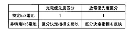
- index is reflected in the charging priority in a division
- the secondary battery when the temperature is high, the secondary battery is charged / discharged so that the frequency of the exothermic reaction is reduced, so that the temperature of the secondary battery is stabilized.
- the secondary battery that preferentially allocates the charging power to the secondary battery that requires correction of the calculated value of the discharge capacity at the end of charging, and does not require correction of the calculated value of the discharge capacity at the end of charging. Since the discharge power is preferentially assigned to the battery, the calculation value of the discharge capacity at the end of charging is corrected quickly.
- a secondary battery in which charging power is preferentially assigned to a secondary battery that does not require correction of the calculated value of the discharge capacity at the end of the discharge, and the calculated value of the discharge capacity at the end of the discharge is required to be corrected Since the discharge power is preferentially assigned to, correction of the calculated value of the discharge capacity at the end of discharge is performed quickly.
- the charging power is preferentially assigned to the secondary battery that has not reached the charging end where the calculation value of the discharge capacity is corrected, and the calculation value of the discharging capacity is corrected. Since the discharge power is preferentially assigned to the secondary battery that has reached, it becomes easy to bring the state of charge closer to the target value after correcting the calculated value of the discharge capacity.
- the charging power is preferentially assigned to the secondary battery that has reached the end of the discharge for which the calculation value of the discharge capacity is corrected, and the end of the discharge is performed for which the calculation value of the discharge capacity is corrected. Since the discharge power is preferentially assigned to the secondary battery that has not been performed, it becomes easy to bring the state of charge closer to the target value after correcting the calculated value of the discharge capacity.
- charge power and discharge power are preferentially assigned to a secondary battery with a small usage history, so the usage history of the secondary battery becomes uniform and the deterioration of the secondary battery becomes uniform.
- the usage history of the secondary battery becomes uniform and the deterioration of the secondary battery becomes uniform.
- charge power and discharge power are preferentially assigned to a specific secondary battery, so that deteriorated secondary batteries are concentrated on the specific secondary battery, and maintenance is facilitated.
- the charge priority category and the discharge priority category to which the first index does not change even if the first index slightly changes often does not change, and thus is caused by frequent changes in the charge priority and the discharge priority.
- the inconvenience is suppressed.
- the usage history of the secondary battery becomes uniform, the deterioration of the secondary battery becomes uniform, and a failure due to the deterioration of any of the plurality of secondary batteries is prevented from occurring at an early stage.
- the twenty-second to twenty-third inventions it is possible to suppress the sudden allocation of the discharge power or the charge power or the cancellation thereof, so that the total charge power or the total discharge power is stabilized.
- charge power and discharge power are preferentially assigned to a specific secondary battery, so that deteriorated secondary batteries are concentrated on the specific secondary battery, and maintenance is facilitated.
- the power for waiting for the bidirectional converter is reduced, and the new charging power or discharging power is quickly assigned to the secondary battery having the highest charging priority or discharging priority. become.
- the processing performed by one control device is reduced, it is easy to control charging / discharging of a large number of secondary batteries.
- the first embodiment relates to a power storage device 1002.
- FIG. 1 is a block diagram of a power storage device 1002 according to the first embodiment.
- the power storage device 1002 includes a NaS battery 1004 that stores power, a connection line 1006 that connects the system 1902 and the NaS battery 1004, and a current detector that measures the charge / discharge current of the NaS battery 1004. 1008, a temperature sensor 1010 for measuring the temperature of the NaS battery 1004, and power supplied from the NaS battery 1004 to the system 1902 is converted from direct current to alternating current, and power supplied from the system 1902 to the NaS battery 1004 is converted from alternating current to direct current.
- Bidirectional converter 1012 for conversion transformer 1014 for boosting power supplied from NaS battery 1004 to system 1902 and reducing power supplied from system 1902 to NaS battery 1004, and control for controlling power storage device 1002 Unit 1016, display unit 1018 for displaying information, and operation for accepting an operation It includes a 1020, a.
- connection line 1006 current detector 1008, temperature sensor 1010, bidirectional converter 1012, and transformer 1014 are provided corresponding to each of the plurality of NaS batteries 1004, and the current detector 1008, bidirectional converter 1012 and the transformer 1014 are inserted into the connection line 1006.
- the current detector 1008 is inserted on the DC side of the bidirectional converter 1012, and the transformer 1014 is inserted on the AC side of the bidirectional converter 1012.
- Each of the four NaS batteries 1004 forms a charge / discharge unit that can be charged / discharged independently. Although four NaS batteries 1004 are shown in FIG. 1, the number of NaS batteries 1004 is increased or decreased according to the specifications of the power storage device 1002. Instead of the NaS battery 1004, other types of secondary batteries may be employed.
- the control unit 1016 charges and discharges power to each of the plurality of NaS batteries 1004 so that the charge / discharge power as a whole of the plurality of NaS batteries 1004 (hereinafter referred to as “total charge / discharge power”) becomes a set value.
- the set value of the total charge / discharge power may be input from the operation unit 1020 or may be input from a microgrid control system of a microgrid provided with the power storage device 1002 via a communication line.
- the input value of the input charge / discharge power does not become the set value as it is, and the set value may be set so that the power consumed in the power storage device 1002 can be secured.
- FIG. 2 is a circuit diagram of the module 1102 of the NaS battery 1004.
- the module 1102 is a serial connection body in which blocks 1104 are connected in series
- the block 1104 is a parallel connection body in which strings 1106 are connected in parallel
- the string 1106 is a series connection in which cells 1108 are connected in series. It is a connected body.
- the number of blocks 1104 connected in series, the number of strings 1106 connected in parallel, and the number of cells 1108 connected in series are increased or decreased according to the specifications of the module 1102.
- the NaS battery 1004 includes one or more modules 1102.
- the number of modules 1102 is increased or decreased according to the specifications of the NaS battery 1004.
- the current detector 1008 measures the charge / discharge current of each of the plurality of NaS batteries 1004.
- the charge / discharge power may be measured indirectly rather than directly. For example, charge / discharge power may be measured and the measured value of charge / discharge power may be converted into charge / discharge current.
- charge / discharge power is converted into charge / discharge current, for example, AC charge / discharge power is measured on the AC side of bidirectional converter 1012, and DC charge / discharge voltage is measured on the DC side of bidirectional converter 1012.
- the charge / discharge current is calculated from the measured value of AC charge / discharge power and the measured value of DC charge / discharge voltage.
- Bidirectional converter 1012 charges / discharges each of a plurality of NaS batteries 1004 according to a charge / discharge command, and controls charging / discharging of each of the plurality of NaS batteries 1004 so that charge / discharge power becomes a command value.
- the bidirectional converter 1012 is also called “PCS (Power Conversion System)”, “AC / DC converter”, or the like.
- PCS Power Conversion System
- AC / DC converter AC / DC converter
- Mutual conversion between direct current and alternating current in the bidirectional converter 1012 is performed by a PWM (Pulse Width Modulation) inverter or the like.
- the entire operation of the bidirectional converter 112 that controls charging / discharging of the unassigned NaS battery may be stopped.
- Some bidirectional converters 1012 other than the bidirectional converter 1012 that controls charging / discharging of the NaS battery 1004 having the highest discharge priority may be stopped. This speeds up the assignment of new charging power or discharging power to the NaS battery 1004 having the highest charging priority or discharging priority.
- the operation of the bidirectional converter 1012 that controls charging / discharging of the NaS battery 1004 having the highest charging priority or discharging priority may be stopped and restarted before new charging power or discharging power is allocated. This speeds up the assignment of new charging power or discharging power to the NaS battery 1004 having the highest charging priority or discharging priority.
- the timing for resuming the operation is determined from the time required for resuming the operation of the bidirectional converter 1012 and the expected value of the time until charge power or discharge power is newly allocated.
- the estimated value of the time until the charging power or the discharging power is newly assigned is the predicted value of the total charging / discharging power and the charging / discharging of the NaS battery 1004 whose charging / discharging is controlled by the operating bidirectional converter 1012. It is calculated from the power and SOC.
- the temperature sensor 1010 measures the temperature of each of the plurality of NaS batteries 1004.
- FIG. 3 is a block diagram of the control unit 1016.
- Each function of the control unit 1016 may be realized by causing an embedded computer including a CPU and a memory to execute a control program, or may be realized by hardware.
- control unit 1016 includes a discharge capacity calculation unit 1202 that calculates the discharge capacity of the NaS battery 1004, an SOC calculation unit 1204 that calculates the SOC of the NaS battery 1004, and the integrated charge / discharge power of the NaS battery 1004.
- End-of-charge / discharge end detection unit 1210 for detecting arrival at the end ranking unit 1212 for assigning charge priority and discharge priority to the NaS battery 1004, and power allocation unit for assigning charge power and discharge power to the NaS battery 1004 1214 and a charge / discharge command unit 1216 that commands the bidirectional converter 1012 to charge / discharge the NaS battery 1004.
- “Calculation” includes not only calculation by an arithmetic expression but also processing such as conversion by a numerical table and calculation by an analog arithmetic circuit.
- “Integration” may be the sum when the time intervals of the integrated values are discrete, or may be the integration when the time intervals of the integrated values are non-discrete. This also applies to the following.
- the SOC calculation unit 1204 calculates the SOC of each of the plurality of NaS batteries 1004 from the calculated value Cm of the discharge capacity calculated by the discharge capacity calculation unit 1202 and the rated capacity. “SOC” is a ratio of the remaining capacity to the rated capacity, but an amount corresponding to the ratio on a one-to-one basis may be regarded as “SOC”.
- the integrated charge / discharge power calculation unit 1206 integrates the charge / discharge power of each of the plurality of NaS batteries 1004 from the start of use of the NaS battery 1004 to the present, and calculates the integrated charge / discharge power of each of the plurality of NaS batteries 1004. To do.
- the accumulated charge / discharge power to be accumulated may be a calculated value Pm calculated in the bidirectional converter 1012 or a measured value Pm measured by a wattmeter inserted in the connection destination 1006.
- the accumulated charge / discharge power is an example of an amount that reflects the history of use of the NaS battery 1004.
- an integrated charge / discharge current calculation unit that calculates the integrated charge / discharge current may be provided instead of the integrated charge / discharge power calculation unit 1206, an integrated charge / discharge current calculation unit that calculates the integrated charge / discharge current may be provided.
- the accumulated charge / discharge current may be the calculated value Im calculated in the bidirectional converter 1012 or the measured value Im measured by the current detector 1008. More generally, a usage history reflection amount calculation that calculates an amount reflecting the usage history of the NaS battery 1004 from the detection result of a detection body that detects the usage state of the NaS battery 1004 such as a wattmeter, a current detector 1008 or the like. Parts are provided.
- the necessity determination unit 1208 determines whether or not correction of the calculated value of the discharge capacity at the end of charging or discharging is necessary for each of the plurality of NaS batteries 1004. In determining whether correction of the calculated value of the discharge capacity is necessary, correction of the calculated value of the discharge capacity of the plurality of NaS batteries 1004 may be performed one by one, or a plurality of NaS batteries. The error of the calculated value of each discharge capacity of 1004 may be estimated, and the calculated value of the discharge capacity of the NaS battery 1004 in which the estimated error has increased may be corrected.
- End of charge / End of discharge detection unit 1210 monitors the voltage of each of the plurality of NaS batteries 1004, and reaches the end of charge or the end of discharge at which the calculated value of the discharge capacity is corrected for each of the plurality of NaS batteries 1004. To detect.
- the ranking unit 1212 reflects the charge prioritization index ICm shown in Expression (1) to give each the NaS battery 1004 a charge priority, and reflects the discharge prioritization index IDm shown in Expression (3). Thus, a discharge priority order is assigned to each of the plurality of NaS batteries 1004.
- the ranking unit 1212 increases the charging priority as the charging priority index ICm increases, and increases the discharging priority as the discharging priority index IDm increases.
- the coefficient AC of the first term of the charge prioritization index ICm takes a positive value
- the coefficient AD of the first term of the discharge prioritization index IDm takes a negative value.
- the charging priority increases and the discharge priority decreases, and the charging power is preferentially assigned to the NaS battery 1004 where the calculated SOC value SOCm is significantly lower than the target value SOCt, and the calculated SOC value SOCm is Since discharge power is preferentially assigned to the NaS battery 1004 that greatly exceeds the target value SOCt, it becomes easy to bring the SOC close to the target value SOCt.
- the charge prioritization index ICm and the discharge prioritization index IDm include the temperature measurement value Tm measured by the temperature sensor 1010 as a first subfactor in the second term.
- the function f (SOCm) increases as the calculated value SOCm of the SOC increases.
- SOCm is relatively small, even if the difference ⁇ T is large, it is difficult to cause a situation where the discharge must be stopped due to the temperature limitation. Therefore, it is desirable to make the coefficient BC relatively small. is there. Further, when the SOCm is relatively large, a situation in which discharge must be stopped due to temperature limitation is likely to occur when the difference ⁇ T is large. Therefore, it is desirable to make the coefficient BC relatively large. It is.
- the coefficient BC of the second term is a negative value
- the NaS battery 1004 having a high temperature measurement value Tm is preferentially charged.
- the temperature of the NaS battery 1004 decreases and ⁇ SOCm decreases, so that the range of discharge time and discharge power that can be discharged to the NaS battery 1004 is expanded. Therefore, setting the coefficient BC of the second term to a negative value is desirable from the viewpoint of expanding the range of discharge time and discharge power that can be discharged to the NaS battery 1004.
- the discharge priority tends to increase, so that there is a high possibility that discharge power is assigned to the charged NaS battery 1004. Accordingly, when the coefficient BC of the second term is a negative value, charging / discharging of the NaS battery 1004 having a high temperature measurement value Tm is repeated, and the temperature of the NaS battery 1004 having a high temperature measurement value Tm is further increased by Joule heat. This causes the problem of becoming high.
- the NaS battery 1004 having a high temperature measurement value Tm is difficult to be charged. While the NaS battery 1004 is not being charged / discharged, the temperature of the NaS battery 1004 gradually decreases due to heat dissipation. The decrease in the temperature of the NaS battery 1004 while charging / discharging is not performed is more gradual than the decrease in the temperature of the NaS battery 1004 while charging is performed. For this reason, in the short term, the range of discharge time and discharge power that can be discharged by the NaS battery 1004 is larger during charging while it is not charged / discharged. .
- the coefficient BC of the second term that can expand the range of discharge time and discharge power that can be discharged to the NaS battery 1004 is the time change of charge / discharge power required for the power storage device 1002. Means different. Therefore, the coefficient of the second term is that the discharge of the NaS battery 1004 to expand the range of discharge time and discharge power according to the track record or prediction of charge / discharge power required for the power storage device 1002. It is desirable to set so that Even when the coefficient of the second term is set to “0”, the operation of the power storage device 1002 is generally an appropriate operation.
- the temperature of the NaS battery 1004 may decrease more rapidly than the temperature of the NaS battery 1004 while charging is being performed. is there.
- the coefficient BC of the second term is preferably a positive value.
- the coefficient BC of the second term is a function of the calculated value SOCm of the SOC.
- the coefficient BD of the second term of the discharge prioritization index IDm is preferably a function of the calculated value SOCm of the SOC as shown in the equation (4), takes a positive value, and takes the first value of the discharge prioritization index IDm.
- the function f ′ (SOCm) decreases as the calculated value SOCm of the SOC increases.
- SOCm is relatively small, even if the difference ⁇ T is large, it is difficult to cause a situation in which the discharge must be stopped due to temperature limitation. Therefore, the function f ′ (SOCm) is relatively large. This is because it is desirable. Further, when SOCm is relatively large, a situation in which discharge must be stopped due to temperature limitation is likely to occur when the difference ⁇ T is large, and therefore the function f ′ (SOCm) is relatively small. This is because it is desirable.
- the discharge priority order may not be given to the NaS battery 1004 with the measured temperature value Tm higher than the threshold value. Good. However, even if the discharge priority is not set, it is allowed to set the charge priority.
- the NaS battery 1004 is a secondary battery in which an endothermic reaction occurs when charged and an exothermic reaction occurs when discharged, the NaS battery 1004 is charged so that the frequency of the exothermic reaction is reduced when the temperature is high. As a result, the temperature of the NaS battery 1004 is stabilized.
- the term coefficient BC takes a positive value.
- the coefficient BC of the second term is preferably a function of the calculated value SOCm of SOC as shown in Expression (2). It is desirable that the function f (SOCm) decreases as the calculated value SOCm of the SOC increases.
- SOCm is relatively large, even if the difference ⁇ Tm increases, it is difficult to cause a situation where charging must be stopped due to temperature limitations. Therefore, the function f (SOCm) may be relatively increased. This is desirable.
- the function f (SOCm) should be relatively small. This is because it is desirable.
- the discharge prioritization index IDm shown in Formula (5) may be used.
- the second term BD ⁇ ⁇ Tm in Expression (3) is replaced with a function f ′′ (SOCm, Tm) of the calculated value SOCm of SOC and the measured value Tm of temperature. It has been.
- the first upper limit value U1m and the second upper limit value U2m of the discharge power are set in each of the plurality of NaS batteries 1004.
- the first upper limit value U1m is the maximum value of the discharge power determined by the specification of the NaS battery 1004 or the specification of the discharge path from the NaS battery 1004, and the power allocation unit 1214 generates a plurality of discharge powers equal to or less than the first upper limit value U1m.
- the second upper limit value U2 is the maximum value of discharge power at which the temperature of the NaS battery 1004 is maintained below the upper limit temperature.
- the second upper limit value U2m is set to be equal to or less than the first upper limit value U1m.
- the first upper limit value U1m may be the same for all of the plurality of NaS batteries 1004, or may be different for all or part of the plurality of NaS batteries 1004.
- the second upper limit value U2m may be the same for all of the plurality of NaS batteries 1004, or may be different for all or some of the plurality of NaS batteries 1004.
- the function f ′′ (SOCm, Tm) includes a ratio U2m / U1m of the second upper limit value U2m to the first upper limit value U1m as a factor, and increases as the ratio U2m / U1m increases. Accordingly, the discharge priority increases as the ratio U2m / U1m increases.
- the second upper limit value U2m is the maximum value of discharge power that allows continuous discharge until the DOD (discharge depth) reaches 100%.
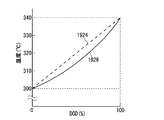
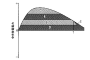
- FIG. 4 is a diagram illustrating an example of information describing the relationship between the DOD and temperature of the NaS battery 1004 at the time of discharging referred to by the ranking unit 1212.
- the discharge power of 1.0 MW, 0.8 MW, and 0.6 MW is discharged from the initial state where the DOD is 0% and the temperature is 300 ° C.
- Changes in DOD and temperature are shown in DOD-temperature characteristic lines 1912, 1914 and 1916, respectively.
- the ranking unit 1212 refers to the reference information describing the relationship between the DOD of the NaS battery 1004 and the temperature shown in FIG. 4, for example, the measured value Tm of the temperature is 300 ° C., and the calculated value DODm of the DOD is 0%. If the discharge power is 0.6 MW or less, the temperature is maintained at the upper limit temperature of 340 ° C. or lower and continuous discharge is possible until the DOD reaches 100%, that is, the second upper limit value U2m is set to 0. It can be seen from the DOD-temperature characteristic line 1916 that it should be 6 MW. Also, if the measured value Tm of the temperature is 305 ° C.
- the temperature is maintained at the upper limit temperature of 340 ° C. or less and the DOD is reduced to 100% if the emission power is 0.8 MW or less It can be seen from the DOD-temperature characteristic line 1918 that continuous discharge is possible until it reaches, that is, the second upper limit value U2m should be 0.8 MW.
- the DOD-temperature characteristic line from the initial state where the temperature is the measured value Tm and the DOD is the calculated value DODm to the final state where the temperature is below the upper limit temperature and the DOD is 100% is specified and specified.
- the discharge power that changes the temperature and DOD of the NaS battery 1004 along the DOD-temperature characteristic line the discharge power can be continuously discharged until the temperature is kept below the upper limit temperature and the DOD reaches 100%.
- An upper limit value U2m of 2 is specified.
- the upper limit value U2m of 2 is made to coincide with the first upper limit value U1m.
- the temperature of the NaS battery 1004 is maintained between the lower limit temperature and the upper limit temperature, and the DOD of the NaS battery 1004 is between 0% and 100%.
- the “upper limit temperature” is determined by the NaS battery 1004. It is desirable to set it lower than the maximum temperature at which it operates normally.
- the second upper limit value U2m having high accuracy is calculated even with a linear DOD-temperature characteristic line 1924 that roughly follows the change in the state of the NaS battery 1004.
- the second upper limit value U2m having higher accuracy is calculated.
- a DOD-temperature characteristic line 1926 shown in FIG. 5 has a bow shape in which the rate of change of temperature with respect to DOD is low immediately after the initial state. The rate of change in temperature relative to DOD immediately after the initial state is affected by the heat capacity and thermal resistance of the NaS battery 1004.
- the maximum value of the discharge power that can be continuously discharged until the DOD reaches 100% may be set as the second upper limit value U2m.
- the charge prioritization index ICm and the discharge prioritization index IDm include the calculated value IPm of the integrated charge / discharge power calculated by the integrated charge / discharge power calculation unit 1206 in the third term as a second subfactor.
- the coefficient CC of the third term of the charge prioritization index ICm and the coefficient CD of the third term of the discharge prioritization index IDm take negative values. Thereby, the charge priority and the discharge priority increase as the calculated value IPm of the integrated charge / discharge power decreases.
- charging power and discharging power are preferentially assigned to the NaS battery 1004 having a small accumulated charging / discharging power, so that the accumulating charging / discharging power of the NaS battery 1004 becomes uniform, and the deterioration of the NaS battery 1004 becomes uniform.
- the calculated value of the integrated charge / discharge current is replaced with the charge prioritization index ICm and the discharge instead of the calculated value IPm of the integrated charge / discharge power.
- Charging power and discharging power are preferentially assigned to the NaS battery 1004 that is included as a second sub-factor in the priority index IDm and has a low integrated charge / discharge current. More generally, the amount reflecting the usage history calculated by the usage history reflection amount calculation unit is included as the second sub-factor in the charge prioritization index ICm and the discharge prioritization index IDm, and the usage history is small. Charge power and discharge power are preferentially assigned to the NaS battery 1004.
- the charge prioritization index ICm and the discharge prioritization index IDm include the determination result of the necessity determination unit 1208 as the third factor in the fourth term,
- the detection result of the end-of-charge / end-of-discharge detection unit 1210 is included in the fourth term as a fourth factor.
- the coefficient DC of the fourth term of the charge prioritization index ICm takes a negative value
- the coefficient DD of the fourth term of the discharge prioritization index IDm takes a positive value, and indicates the state of correction of the calculated value of the discharge capacity.
- the expressed value Sm changes from 0 to ⁇ 1 when the necessity determining unit 1208 determines that the calculation value of the discharge capacity at the end of charging is necessary, and the charging end / discharge end detecting unit 1210 returns to the end of charging.
- -1 is changed to 1 when the arrival is detected, and is changed from 1 to 0 when the SOC approaches the target value SOCt.
- the necessity determination unit 1208 determines that the calculation value of the discharge capacity at the end of charging is required to be corrected, the charging priority is increased and the discharging priority is decreased.
- the end of charge / discharge end detection unit 1210 detects the end of charge, the charge priority is lowered and the discharge priority is raised.
- charging power is preferentially assigned to the NaS battery 1004 that requires correction of the calculated value of the discharge capacity at the end of charging, and preferentially discharged to the NaS battery 1004 that does not require correction of the calculated value of the discharge capacity at the end of charging. Since electric power is allocated, the calculation value of the discharge capacity at the end of charging is quickly corrected. Further, since the charging power is preferentially assigned to the NaS battery 1004 that has not reached the end of charging, and the discharging power is preferentially assigned to the NaS battery 1004 that has reached the end of charging, the calculated value of the discharge capacity at the end of charging is calculated. It becomes easy to bring the SOC close to the target value after the correction.
- the necessity determination unit 1208 determines that correction of the calculated value of discharge capacity at the end of discharge is necessary, the charge priority is lowered and the discharge priority is raised. Should. In addition, when the end of charge / end of discharge detection unit 1210 detects arrival of the end of discharge, the charge priority should be raised and the discharge priority should be lowered. For this reason, the coefficient DC of the fourth term of the charge prioritization index ICm takes a positive value, the coefficient DD of the fourth term of the discharge prioritization index IDm takes a negative value, and the calculation value of the discharge capacity is corrected.
- the value changes from -1 to 1, and when the SOC approaches the target value SOCt, the value changes from 1 to 0.
- charging power is preferentially assigned to the NaS battery 1004 that does not require correction of the calculated value of the discharge capacity at the end of discharge, and preferentially discharged to the NaS battery 1004 that requires correction of the calculated value of the discharge capacity at the end of discharge. Since electric power is allocated, the calculation value of the discharge capacity at the end of the discharge is quickly corrected.
- the charging power is preferentially assigned to the NaS battery 1004 that has reached the end of discharge
- the discharging power is preferentially assigned to the NaS battery 1004 that has not reached the end of discharge, after correcting the calculated value of the discharge capacity In this case, it is easy to bring the SOC close to the target value.
- the absolute values of the coefficients AC, BC, CC, and DC indicate the magnitude of the contribution of the main factor, the first subfactor, the second subfactor, the third and fourth subfactors to the charging priority, respectively.
- the absolute values of the coefficients AD, BD, CD, and DD are the magnitudes of contribution of the main factor, the first sub-factor, the second sub-factor, the third and fourth sub-factors to the charging priority, respectively. Indicates. When the charging priority is increased as the charging priority index ICm decreases, the signs of the coefficients AC, BC, CC, and DC are reversed, and when the discharging priority is increased as the discharge priority index IDm decreases, the coefficient AD , BD, CD, DD are inverted.
- the charge prioritization index ICm shown in Expression (1) and the discharge prioritization index IDm shown in Expression (3) are examples, and are changed according to the specifications of the power storage device 1002. In particular, it is naturally planned to delete all or part of the first to third subfactors and to add subfactors other than the first to third subfactors.
- the charge prioritization index ICm and the discharge prioritization index IDm may be shared.
- the power allocating unit 1214 sequentially allocates charging power from the NaS battery 1004 with a high charging priority assigned by the ranking unit 1212 to the NaS battery 1004 with a low charging priority, and the NaS battery 1004 with a high discharging priority assigned by the ranking unit 1212. To the lower NaS battery 1004 in order. In assigning the charging power to each of the plurality of NaS batteries 1004, if the unassigned charging power is greater than the maximum charging power of the NaS battery 1004, the maximum charging power is assigned, and the unassigned charging power is assigned to the NaS battery 1004. If the charging power is equal to or less than the maximum charging power of the NaS battery 1004, all of the unassigned charging power is allocated.
- the unassigned discharge power is larger than the maximum discharge power of the NaS battery 1004, the maximum discharge power is assigned, and the unassigned discharge power is If the maximum discharge power of the NaS battery 1004 is equal to or less than the maximum discharge power of the NaS battery 1004, all of the unassigned discharge power is allocated.
- the charging priority is 1 MW that is the same as the maximum charging power for the first NaS battery 1004. Charging power is allocated, the remaining charging power of 0.5 MW is allocated to the NaS battery 1004 with the second charging priority, and charging power is not allocated to the third and fourth NaS batteries 1004 with the charging priority. .
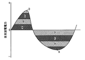
- FIG. 6 is a graph for explaining the reflection of charging priority and discharging priority on allocation of charging power and discharging power.
- FIG. 7 is a graph for explaining the reflection of the charging priority order to the allocation of charging power.
- time is plotted on the horizontal axis and total charge / discharge power is plotted on the vertical axis.
- Positive total charge / discharge power represents total charge power
- negative charge / discharge power represents total discharge power.
- the charging power and the discharging power allocated to the NaS batteries A, B, C, and D are represented by their own hatching.
- the charge / discharge command unit 1216 instructs the bidirectional converter 1012 to charge / discharge the charge / discharge power allocated by the power allocation unit 1214.
- the charge / discharge command unit 1216 determines that the necessity determination unit 1208 determines that the calculation value of the discharge capacity needs to be corrected until the charge end or the end of discharge at which the calculation value of the discharge capacity is corrected.
- a command for charging / discharging is output to bidirectional converter 1012.
- charge / discharge command unit 1216 controls the stop and restart of the operation of the bidirectional converter 1012.
- FIG. 8 is a graph showing the relationship between the discharge depth of NaS battery 1004 and the voltage.
- Correction of the calculated value of the discharge capacity is performed in a state where the NaS battery 1004 is charged until the end of charging, or in a state where the NaS battery 1004 is discharged until the end of discharge (the depth of discharge included in one phase region). Is called.
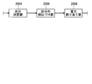
- the mode of operation of the power storage device 1002 is broadly divided into pattern operation and power smoothing operation.
- the pattern operation is an operation in which charging / discharging is performed in accordance with fluctuations in the daily power demand.
- pattern operation is generally performed in which charging is performed at night when power demand is low and discharging is performed during the day when power demand is low.
- charge / discharge power for each time is often set in advance.
- Power smoothing operation is an operation that performs charging and discharging according to shorter fluctuations in power demand.
- the SOC target value SOCt is often set to about 50%.
- the SOC target value SOCt is temporarily set near 100% when the calculated value of the discharge capacity of the NaS battery 1004 is corrected at the end of charging, and the NaS battery When the calculated value of the discharge capacity of 1004 is corrected at the end of the discharge, it is temporarily set near 0%.
- Allocation of charging power and discharging power to each of the plurality of NaS batteries 1004 may be performed manually.
- the power storage device 1002 displays the discharging priority order and the charging priority order on the display unit 1115, and operates the input of the charging power and discharging power allocation. Accepted by the unit 1020. In addition to the discharge priority and the charge priority, a recommended charge power and discharge power allocation may be displayed on the display unit 1115.
- the charging power and discharging power received by the operation unit 1020 are sent to the charge / discharge command unit 1236.
- the second embodiment relates to a category determination unit 2004, an intra-segment ranking unit 2006, and a power allocation unit 2008 that are employed instead of the ranking unit 1212 and the power allocation unit 1214 of the first embodiment.
- the main difference between the first embodiment and the second embodiment is the mode of determining the charging priority and discharging priority of the NaS battery 1004.
- the intra-category prioritization index Km is reflected in the intra-category charge priority and the intra-category discharge priority of the NaS battery 1004. Further, charging power is assigned in order from the NaS battery 1004 having a higher charge priority category to the lower NaS battery 1004, and discharging power is assigned in order from the NaS battery 1004 having a higher discharge priority category to the lower NaS battery 1004. Further, for the NaS batteries 1004 having the same charge priority category, the charge power is assigned in order from the NaS battery 1004 having the highest in-category charge priority to the lower NaS battery 1004, and for the NaS batteries 1004 having the same discharge priority category. Discharge power is assigned in order from the NaS battery 1004 having the highest internal discharge priority to the NaS battery 1004 having the lower priority.
- “Charge priority” and “discharge priority” in the first embodiment are “charge priority” and “discharge priority”, respectively.
- two or more NaS batteries 1004 are provided. The same “charging priority” and “discharging priority” are not given repeatedly.
- “charge priority” and “discharge priority” in the second embodiment are “charge priority category” and “discharge priority category”, respectively.
- two or more units are used. The NaS battery 1004 may overlap and belong to the same “charge priority category” and “discharge priority category”.
- a classification determination unit 2004 that determines a charge priority category and a discharge priority category to which the NaS battery 1004 belongs, and a NaS battery for each charge priority category and discharge priority category.
- An intra-segment ranking unit 2006 that assigns the intra-category charge priority and intra-category discharge priority to 1004, and a power allocation unit 2006 that allocates charge power and discharge power to the NaS battery 1004 are provided.
- the division determination unit 2004 stratifies the plurality of NaS batteries 1004 by reflecting the classification determination index Jm shown in Expression (6), and determines the charge priority category and the discharge priority category to which each of the plurality of NaS batteries 1004 belongs. .
- the category determination unit 2004 increases the charge priority category and decreases the discharge priority category as the category determination index Jm increases.
- ⁇ SOCm SOCt ⁇ SOCm with respect to the calculated value SOCm of the SOC calculated by the SOC calculation unit 1204 of the SOC target value SOCt as a main factor.
- the classification determination index Jm may include the same subfactor as the subfactor included in the charge prioritization index ICm and the discharge prioritization index IDm of the first embodiment. However, in this case, as described in the column of “Commonization of Charging Prioritization Index ICm and Discharge Prioritization Index IDm” in the first embodiment, the index for setting the charging priority and the discharge priority are set. It may be necessary to separate the index for attaching.
- FIG. 10 is a diagram illustrating the charging priority classification according to the second embodiment.
- the plurality of charge priority categories are classified according to the threshold value of the category determination index Jm. For example, when there are three charging priority categories, as shown in FIG. 10, the threshold TH12 for dividing the first charging priority category and the second charging priority category is set to 20%, and the second charging priority level is set.
- the threshold TH23 that separates the section from the third charge priority section is set to ⁇ 20%.
- the NaS battery 1004 with ⁇ SOCm ⁇ 20% belongs to the first charge priority category
- the NaS battery 1004 with 20% ⁇ ⁇ SOCm ⁇ ⁇ 20% belongs to the second charge priority category
- ⁇ 20% ⁇ ⁇ SOCm NaS battery 1004 belongs to the third charge priority category.
- the discharge priority category is also classified by the threshold value of the category determination index Jm.
- the intra-sector ranking unit 2006 reflects the intra-sector ranking index Km shown in Equation (7), assigns an intra-sector priority to each of the NaS batteries 1004 for each charge priority category, and sets the priority for each discharge priority category. Each NaS battery 1004 is given an intra-section discharge priority.
- the intra-segment ranking unit 2006 increases the intra-segment charging priority and the intra-segment discharge priority as the intra-segment ranking index Km decreases.
- the intra-section ranking index Km includes the calculated value IPm of the integrated charge / discharge power calculated by the integrated charge / discharge power calculation unit 1206 as a first factor. Thereby, the charge priority and the discharge priority increase as the calculated value IPm of the integrated charge / discharge power decreases. As a result, charging power and discharging power are preferentially assigned to the NaS battery 1004 with low accumulated charging / discharging power, so that the integrated charging / discharging power of the NaS battery 1004 becomes uniform, and the deterioration of the NaS battery 1004 becomes uniform.
- the amount reflecting the usage history such as the cumulative charging / discharging current instead of the cumulative charging / discharging power is included as the first factor in the in-category ranking index Km, and the charging power and discharging are preferentially applied to the NaS battery 1004 with a small usage history. Electric power may be allocated.
- the intra-segment ranking index Km is an index different from the intra-segment ranking index Jm, and the factor included in the intra-segment ranking index Km and the factor included in the intra-segment determination index Jm do not overlap. Accordingly, the intra-category ranking index Km different from the intra-segment determination index Jm is reflected in the intra-category priority and intra-category discharge priority, so that charging power and discharging power are more appropriately assigned.
- the intra-category ranking index Km is replaced with the first factor or in addition to the first factor, the following second to fourth These factors may be included, or factors other than the following second to fourth factors may be included.
- an index and an intra-category index for assigning an intra-category charge priority may be necessary to separate the index for setting the discharge priority.
- the intra-segment ranking index Km may include the temperature measurement value Tm measured by the temperature sensor 1010 as the second factor, and the intra-segment ranking unit 2006 increases the temperature measurement value Tm.
- the charging priority may be raised and the intra-segment discharge priority may be lowered.
- the intra-category ranking index Km includes the determination result of the necessity determining unit 1208 as a factor, and the intra-category ranking unit 2006 uses the necessity determining unit 1208 to determine the end of charging.
- the in-category charge priority may be raised and the in-category discharge priority may be lowered.
- the intra-category ranking index Km includes the detection result of the end-of-charge / discharge end detecting unit 1210 as a factor, and the intra-category ranking unit 2006 determines the end of charging /
- the in-category charge priority may be lowered and the in-category discharge priority may be raised.
- the intra-segment ranking unit 2006 lowers the intra-segment charging priority as the temperature measurement value Tm increases.
- the intra-segment ranking unit 2006 determines that the correction of the calculated value of the discharge capacity at the end of the discharge is necessary by the necessity determination unit 1208. Lower priority and increase discharge priority within category.
- the intra-segment ranking unit 2006 increases the intra-segment charge priority when the end of discharge is detected by the end of charge / end of discharge detection unit 1210. Lower the discharge priority within the category.
- the factor included in the intra-category ranking index Km brings the same effect as that included in the charge prioritization index ICm and the discharge prioritization index IDm of the first embodiment.
- the power allocation unit 2008 allocates charging power in order from the NaS battery 1004 having the higher charge priority category to which it belongs, determined by the category determination unit 2004, to the lower NaS battery 1004, and the discharge priority category to which the category determination unit 2004 belongs is assigned. Discharge power is allocated in order from the high NaS battery 1004 to the low NaS battery 1004. Further, the power allocation unit 2008 assigns the charging power in order from the NaS battery 1004 with the highest intra-segment charge priority assigned by the intra-segment ranking unit 2006 to the lower NaS battery 1004 for the NaS batteries 1004 with the same charge priority category. For the NaS batteries 1004 with the same assigned discharge priority category, the discharge power is assigned in order from the NaS battery 1004 with the highest intra-category discharge priority assigned by the intra-segment ranking unit 2006 to the lower NaS battery 1004.
- the third embodiment relates to the ranking of the intra-category charge priority and the intra-category discharge priority adopted instead of the intra-category charge priority and the intra-category discharge priority of the second embodiment.
- FIG. 11 is a diagram for explaining the prioritization of in-category charging priority according to the third embodiment.
- FIG. 11 shows the in-section charging priority of the NaS batteries 1, 2,..., N when the time has elapsed as T1, T2, T3, T4,.
- the intra-category charging priority is cyclically switched over time.
- the ranking of the discharge priority within the category is performed in the same manner.
- the fourth embodiment relates to ranking of charging priority and discharging priority employed instead of ranking of charging priority and discharging priority of the first embodiment.
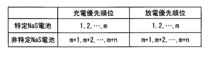
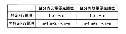
- FIG. 12 is a diagram for explaining the order of charge priority and discharge priority according to the fourth embodiment.
- FIG. 12 shows the charge priority and discharge of m specific NaS batteries 1004 (hereinafter referred to as “specific NaS batteries”) and NaS batteries 1004 other than the specific NaS batteries (hereinafter referred to as “non-specific NaS batteries”). Indicates the priority order.
- the highest charging priority and discharging priority are assigned to the specific NaS battery. That is, the first to mth charging priorities and discharging priorities are assigned to specific NaS batteries, and the (m + 1) th to m + nth charging priorities and discharging priorities are assigned to non-specific NaS batteries.
- charge power and discharge power are preferentially assigned to the specific NaS battery, so that the deteriorated NaS battery 1004 concentrates on the specific NaS battery, and maintenance becomes easy.
- the charge priority and the discharge priority assigned to the specific NaS battery may be fixed, but the charge priority index ICm and the discharge priority index IDm may be reflected, or when time passes. You may make it replace
- the non-specific NaS battery is given a charge priority and a discharge priority by reflecting the charge prioritization index ICm and the discharge prioritization index IDm.
- the specific NaS battery may be a NaS battery 1004 selected in advance. However, if the NaS battery 1004 in which a failure has occurred in the cell is a specific NaS battery, the NaS battery 1004 in which the failure has occurred in the constituent cells will deteriorate. Concentration and easy maintenance.
- the fifth embodiment relates to determination of a charge priority category and a discharge priority category employed instead of the determination of the discharge priority category and the charge priority category of the second embodiment.
- FIG. 13 is a diagram for explaining determination of the charge priority category and the discharge priority category of the fifth embodiment.
- FIG. 13 shows charge priority categories and discharge priority categories of m specific specific NaS batteries and n non-specific NaS batteries.
- the discharge priority category to which the specific NaS battery belongs and the first discharge priority category having the highest charge priority category. And the charging priority category.
- charge power and discharge power are preferentially assigned to the specific NaS battery, so that the deteriorated NaS battery 1004 concentrates on the specific NaS battery, and maintenance becomes easy.
- the intra-category charge priority and intra-category discharge priority assigned to a specific NaS battery may be fixed, but the intra-category ranking index Km may be reflected, and cyclically as time passes. You may make it replace.
- the discharge priority classification and the charge priority classification to which the non-specific NaS battery belongs are determined by reflecting the classification determination index Jm as in the second embodiment, and the non-specific NaS battery is classified in the same category as in the second embodiment. Reflecting the ranking index Km, the intra-category charge priority and the intra-category discharge priority are assigned.
- the sixth embodiment relates to the ranking of the intra-category charge priority and the intra-category discharge priority employed instead of the intra-category charge priority and the intra-category discharge priority of the second embodiment.
- FIG. 14 is a diagram illustrating the ranking of the in-category charge priority and the in-category discharge priority in the sixth embodiment.
- FIG. 14 shows the intra-category charge priority and intra-category discharge priority of m specific NaS batteries and n non-specific NaS batteries belonging to one charge priority category and discharge priority category.
- the highest intra-segment charge priority and intra-segment discharge priority are assigned to the specific NaS battery. That is, the first to mth intra-section charge priority and intra-section discharge priority are assigned to the specific NaS battery, and the m + 1-th to m + n-th intra-section charge priority and intra-section discharge priority are non-specific NaS batteries. It is attached to. Thereby, charge power and discharge power are preferentially assigned to the specific NaS battery, so that the deteriorated NaS battery 1004 concentrates on the specific NaS battery, and maintenance becomes easy.
- the intra-category charge priority and intra-category discharge priority assigned to a specific NaS battery may be fixed, but the intra-category ranking index Km may be reflected, and cyclically as time passes. You may make it replace.
- the non-specific NaS battery is given an intra-category charge priority and an intra-category discharge priority reflecting the intra-category ranking index Km.
- the charging priority assigned to the charging power allocation and the charging priority assigned to the discharging power assigned in the first embodiment are replaced with the charging priority assigned charging power allocation.
- the present invention relates to reflection and reflection of allocation of discharge priority to discharge power.
- FIG. 15 is a graph for explaining the reflection of the charging priority of the seventh embodiment on the allocation of charging power.
- time is plotted on the horizontal axis and total charge / discharge power is plotted on the vertical axis.
- Positive total charge / discharge power represents charge power
- negative charge / discharge power represents discharge power.
- charging power assigned to the NaS batteries A, B, C, and D is represented by hatching specific to each.
- the charging priority assigned to the charging power allocation and the charging priority assigned to the discharging power assigned in the first embodiment are replaced with the charging priority assigned charging power allocation.
- the present invention relates to reflection and reflection of allocation of discharge priority to discharge power.
- FIG. 16 is a graph for explaining the reflection of the charging priority of the eighth embodiment on the allocation of charging power.
- time is plotted on the horizontal axis and total charge / discharge power is plotted on the vertical axis.
- Positive total charge / discharge power represents charge power
- negative charge / discharge power represents discharge power.
- the charging power assigned to the NaS batteries A, B, C, and D is represented by hatching specific to each.
- the ninth embodiment relates to a charge priority category and a discharge priority category adopted instead of the charge priority category and the discharge priority category of the second embodiment.
- FIG. 17 is a diagram for explaining the charging priority classification according to the ninth embodiment.
- the plurality of charge priority categories are divided by the threshold value of the category determination index Jm.
- the threshold for lowering the charge priority category is shifted to the lower charge priority than the threshold for increasing the charge priority category, and the discharge priority category is lower than the threshold for increasing the discharge priority category. Is shifted to a lower discharge priority. Thereby, the inconvenience resulting from the frequent change of the charge priority category and the discharge priority category is suppressed.
- the threshold TH12U when raising the charge priority category from the second to the first is set to 21%, and the charge priority from the first to the second.
- the threshold value TH12D for lowering the classification is set to 19%.
- the threshold TH23U when lowering the charging priority classification from the third to the second is set to -19%, and the threshold value raising the charging priority classification from the second to the third is set to -21%.
- the tenth embodiment relates to a power storage network 10002.
- the power storage network 10002 of the tenth embodiment is provided with a control device that controls charging / discharging of a plurality of charging / discharging units.
- the plurality of control devices constitutes a hierarchical control device network, and information necessary for determining an index or an index, a maximum charge power, and a maximum discharge power are notified from the lower level control device to the higher level control device.
- the lower control device is notified of the allocation of charging power and discharging power.
- the “charge / discharge unit” is a unit for performing charge / discharge independently, and may mean a power storage device including a control device, or may refer to a NaS battery itself that does not include a control device.
- FIG. 18 is a block diagram of the power storage network 10002 of the tenth embodiment.
- charging / discharging of the plurality of NaS batteries 10004 is controlled by the control device 10006, and charging / discharging of the plurality of NaS batteries 10008 is controlled by the control device 10010.
- the plurality of NaS batteries 10004 and the control device 10006 constitute a charge / discharge unit 10012
- the plurality of NaS batteries 10008 and the control device 10010 also constitute a charge / discharge unit 10014.
- Charging / discharging of the NaS battery 10016 which comprises a charging / discharging unit by charging / discharging unit 10012 and 10014 and itself is controlled by the control apparatus 10018.
- the charge / discharge units 10012 and 10014, the NaS battery 10016, and the control device 10018 constitute a larger charge / discharge unit 10020.
- charging / discharging of the plurality of NaS batteries 10022 is controlled by the control device 10024.
- the plurality of NaS batteries 10022 and the control device 10024 constitute a charge / discharge unit 10026.
- Charging / discharging of the NaS battery 10022 which constitutes charging / discharging unit by itself and charging / discharging unit 10026 is controlled by the control apparatus 10030.
- the charge / discharge unit 10026, the NaS battery 1000028, and the control device 10030 constitute a larger charge / discharge unit 10032.
- Charging / discharging of the charging / discharging units 10020, 10032 is controlled by the control device 10034.
- the control devices 10006, 10010, 10018, 10024, 10030, and 10034 regard the charging / discharging unit as a NaS battery, and the control device of the first embodiment or the control device of the first embodiment is the second embodiment to the tenth embodiment.
- the charge / discharge of the charge / discharge unit is controlled in the same manner as in the control device to which the modification described above is added.
- the number of NaS batteries and control devices provided in the power storage network 10002 is increased or decreased according to the specifications of the power storage network 10002, and the number of layers in the control device network is increased or decreased according to the specifications of the power storage network 10002.
- FIG. 19 is a block diagram of the lower order control device 10102 included in the first charge / discharge unit whose charge / discharge is controlled by the higher order control device 10104 and the higher order control device 10104 that controls the charge / discharge of the plurality of first charge / discharge units. is there.
- the control device 10006 serves as the lower control device 10102
- the control device 10018 serves as the higher control device 10104
- the charge / discharge units 10012 and 10014 and the NaS battery 10016 serve as the first charge / discharge unit.
- the upper control apparatus 10104 includes a communication unit 10106 that communicates with the lower control apparatus 10102, a power allocation determination unit 10108 that determines allocation of charge power and discharge power to the first charge / discharge unit, Is provided.
- the communication unit 10106 transmits the assigned charging power and discharging power to the lower-level control device 10102, and information necessary for specifying an index or an index reflected in the charging priority and the discharging priority from the lower-level control device 10102.
- the maximum charge power and the maximum discharge power are received. “Information necessary for specifying an index” includes, for example, factors included in the index.
- the power allocation determining unit 10108 regards the first charging / discharging unit as a NaS battery, reflects the index received from the communication unit 10106 or the information necessary to identify the index, and reflects the first charging / discharging unit.
- the charge priority and the discharge priority of the discharge unit are determined, the charge power is assigned in order from the first charge / discharge unit having the highest charge priority to the first charge / discharge unit having the lower charge priority, and the charge priority is decreased from the charge / discharge unit having the higher discharge priority.
- Discharge power is allocated to charge / discharge units in order.
- the lower-level control apparatus 10102 determines the power allocation determination that determines the allocation of the charging power and the discharge power to the communication unit 10110 that communicates with the higher-level control apparatus 10104 and the second charge / discharge unit whose charging / discharging is controlled by the lower-level control apparatus 10102 Unit 10112.
- the communication unit 10110 receives the assigned charging power and discharging power from the host controller 10104, and transmits information necessary for specifying the index or the index, the maximum charging power and the maximum discharging power to the host controller 10104.
- the maximum charging power transmitted by the communication unit 10110 is the sum of the maximum charging powers of each of the plurality of second charging / discharging units, and the maximum discharging power transmitted by the communication unit 10110 is the plurality of second charging / discharging units. It is the sum of each maximum discharge power.
- the power allocation unit 10112 divides the allocated charging power and discharging power received by the communication unit 10102 and allocates them to the second charging / discharging unit.
- the eleventh embodiment relates to a microgrid 11004 including a power storage device 11002.
- FIG. 20 is a block diagram of the microgrid 11004 of the eleventh embodiment.
- a “microgrid” is a small-scale power supply network in which a distributed power source is installed in a place where power is demanded, and is also called a “distributed energy system” or the like.
- a distributed power source 11006 As shown in FIG. 20, in the microgrid 11004, a distributed power source 11006, a load 11008, and a power storage device 11002 are connected to the system 11010. The operation of the distributed power source 11006, the load 11008, and the power storage device 11002 is controlled by the microgrid control system 11012.
- the distributed power source 11006 is not particularly limited, but a generator using sunlight or other natural energy, for example, a solar power generator is used.
- a fuel cell or the like that uses, as a fuel, a gas produced using raw garbage, waste wood, waste plastic, or the like as a raw material may be used as the distributed power source 11006.
- All or part of the power generated by the distributed power source 11006 is transmitted to the power storage device 11002 via the system 11010 and accumulated in the power storage device 11002.
- the power storage device 1002 according to the first embodiment or the power storage device obtained by adding the modifications described in the second to ninth embodiments to the power storage device 1002 according to the first embodiment is employed.
Abstract
La présente invention concerne un contrôleur, un réseau de contrôleur et un procédé de contrôle de charge/décharge qui permet d'amener l'état de charge (SOC) d'une batterie rechargeable proche d'une valeur cible. Un indice de rang comprenant comme principal facteur la différence (ΔSOCm = SOCt - SOCm) entre la valeur cible (SOCt) de l'état de charge et la valeur calculée (SOCm) de l'état de charge est influencé par le rang prioritaire de charge et le rang prioritaire de décharge d'une batterie NaS. En outre, l'alimentation de charge est allouée en ordre depuis les batteries NaS ayant une rang prioritaire élevé de charge à des batteries NaS ayant un rang prioritaire faible de charge, et l'alimentation de décharge est allouée en ordre depuis des batteries NaS ayant un rang prioritaire élevé de décharge à des batteries NaS ayant un rang prioritaire faible de décharge.
Priority Applications (4)
| Application Number | Priority Date | Filing Date | Title |
|---|---|---|---|
| EP10821843.9A EP2487771B1 (fr) | 2009-10-05 | 2010-09-16 | Contrôleur, réseau de contrôleur et procédé de contrôle |
| CN201080041894.9A CN102577010B (zh) | 2009-10-05 | 2010-09-16 | 控制装置、控制装置网以及控制方法 |
| JP2011535326A JP5628820B2 (ja) | 2009-10-05 | 2010-09-16 | 制御装置、制御装置網及び制御方法 |
| US13/419,794 US8928288B2 (en) | 2009-10-05 | 2012-03-14 | Controller, controller network and control method |
Applications Claiming Priority (2)
| Application Number | Priority Date | Filing Date | Title |
|---|---|---|---|
| JP2009-231260 | 2009-10-05 | ||
| JP2009231260 | 2009-10-05 |
Related Child Applications (1)
| Application Number | Title | Priority Date | Filing Date |
|---|---|---|---|
| US13/419,794 Continuation US8928288B2 (en) | 2009-10-05 | 2012-03-14 | Controller, controller network and control method |
Publications (1)
| Publication Number | Publication Date |
|---|---|
| WO2011043172A1 true WO2011043172A1 (fr) | 2011-04-14 |
Family
ID=43856645
Family Applications (1)
| Application Number | Title | Priority Date | Filing Date |
|---|---|---|---|
| PCT/JP2010/066010 WO2011043172A1 (fr) | 2009-10-05 | 2010-09-16 | Contrôleur, réseau de contrôleur et procédé de contrôle |
Country Status (5)
| Country | Link |
|---|---|
| US (1) | US8928288B2 (fr) |
| EP (1) | EP2487771B1 (fr) |
| JP (1) | JP5628820B2 (fr) |
| CN (1) | CN102577010B (fr) |
| WO (1) | WO2011043172A1 (fr) |
Cited By (40)
| Publication number | Priority date | Publication date | Assignee | Title |
|---|---|---|---|---|
| JP2013099233A (ja) * | 2011-11-07 | 2013-05-20 | Toyota Motor Corp | バッテリの充電システム |
| US20130234669A1 (en) * | 2011-08-31 | 2013-09-12 | North Carolina State University | Intelligent integrated battery module |
| CN103563210A (zh) * | 2011-05-31 | 2014-02-05 | 株式会社Lg化学 | 包括模块化bms连接结构的电力储存系统及其控制方法 |
| JP2014524099A (ja) * | 2011-05-31 | 2014-09-18 | エルジー・ケム・リミテッド | モジュール化されたbms連結構造を含む電力貯蔵システム及びその制御方法 |
| WO2014167802A1 (fr) * | 2013-04-12 | 2014-10-16 | パナソニック 株式会社 | Système de gestion d'accumulateurs électriques et procédé de gestion d'accumulateurs électriques |
| US9219879B2 (en) | 2009-11-13 | 2015-12-22 | Corning Optical Communications LLC | Radio-over-fiber (ROF) system for protocol-independent wired and/or wireless communication |
| US9240835B2 (en) | 2011-04-29 | 2016-01-19 | Corning Optical Communications LLC | Systems, methods, and devices for increasing radio frequency (RF) power in distributed antenna systems |
| US9253003B1 (en) | 2014-09-25 | 2016-02-02 | Corning Optical Communications Wireless Ltd | Frequency shifting a communications signal(S) in a multi-frequency distributed antenna system (DAS) to avoid or reduce frequency interference |
| US9258052B2 (en) | 2012-03-30 | 2016-02-09 | Corning Optical Communications LLC | Reducing location-dependent interference in distributed antenna systems operating in multiple-input, multiple-output (MIMO) configuration, and related components, systems, and methods |
| US9319138B2 (en) | 2010-02-15 | 2016-04-19 | Corning Optical Communications LLC | Dynamic cell bonding (DCB) for radio-over-fiber (RoF)-based networks and communication systems and related methods |
| US9325429B2 (en) | 2011-02-21 | 2016-04-26 | Corning Optical Communications LLC | Providing digital data services as electrical signals and radio-frequency (RF) communications over optical fiber in distributed communications systems, and related components and methods |
| WO2016063351A1 (fr) * | 2014-10-21 | 2016-04-28 | 東芝三菱電機産業システム株式会社 | Dispositif de gestion de charge/décharge |
| US9338823B2 (en) | 2012-03-23 | 2016-05-10 | Corning Optical Communications Wireless Ltd | Radio-frequency integrated circuit (RFIC) chip(s) for providing distributed antenna system functionalities, and related components, systems, and methods |
| JP2016131434A (ja) * | 2015-01-13 | 2016-07-21 | 住友電気工業株式会社 | エネルギー管理システム、エネルギー管理方法及びコンピュータプログラム |
| US9420542B2 (en) | 2014-09-25 | 2016-08-16 | Corning Optical Communications Wireless Ltd | System-wide uplink band gain control in a distributed antenna system (DAS), based on per band gain control of remote uplink paths in remote units |
| US9455784B2 (en) | 2012-10-31 | 2016-09-27 | Corning Optical Communications Wireless Ltd | Deployable wireless infrastructures and methods of deploying wireless infrastructures |
| US9525472B2 (en) | 2014-07-30 | 2016-12-20 | Corning Incorporated | Reducing location-dependent destructive interference in distributed antenna systems (DASS) operating in multiple-input, multiple-output (MIMO) configuration, and related components, systems, and methods |
| US9525488B2 (en) | 2010-05-02 | 2016-12-20 | Corning Optical Communications LLC | Digital data services and/or power distribution in optical fiber-based distributed communications systems providing digital data and radio frequency (RF) communications services, and related components and methods |
| US9531452B2 (en) | 2012-11-29 | 2016-12-27 | Corning Optical Communications LLC | Hybrid intra-cell / inter-cell remote unit antenna bonding in multiple-input, multiple-output (MIMO) distributed antenna systems (DASs) |
| CN106803680A (zh) * | 2016-09-22 | 2017-06-06 | 蔚来汽车有限公司 | 梯次电池组储能电站的能量管理方法和系统 |
| US9729267B2 (en) | 2014-12-11 | 2017-08-08 | Corning Optical Communications Wireless Ltd | Multiplexing two separate optical links with the same wavelength using asymmetric combining and splitting |
| US9730228B2 (en) | 2014-08-29 | 2017-08-08 | Corning Optical Communications Wireless Ltd | Individualized gain control of remote uplink band paths in a remote unit in a distributed antenna system (DAS), based on combined uplink power level in the remote unit |
| JP2017163711A (ja) * | 2016-03-09 | 2017-09-14 | 大和ハウス工業株式会社 | 電力供給システム |
| US9775123B2 (en) | 2014-03-28 | 2017-09-26 | Corning Optical Communications Wireless Ltd. | Individualized gain control of uplink paths in remote units in a distributed antenna system (DAS) based on individual remote unit contribution to combined uplink power |
| US9813229B2 (en) | 2007-10-22 | 2017-11-07 | Corning Optical Communications Wireless Ltd | Communication system using low bandwidth wires |
| JP2018057199A (ja) * | 2016-09-30 | 2018-04-05 | Necプラットフォームズ株式会社 | 電力制御装置、電力制御方法、及び電力制御システム |
| CN108092301A (zh) * | 2016-11-23 | 2018-05-29 | 江苏三棱智慧物联发展股份有限公司 | 一种复合可再生能源发电系统移动控制系统 |
| US10014944B2 (en) | 2010-08-16 | 2018-07-03 | Corning Optical Communications LLC | Remote antenna clusters and related systems, components, and methods supporting digital data signal propagation between remote antenna units |
| US10096909B2 (en) | 2014-11-03 | 2018-10-09 | Corning Optical Communications Wireless Ltd. | Multi-band monopole planar antennas configured to facilitate improved radio frequency (RF) isolation in multiple-input multiple-output (MIMO) antenna arrangement |
| US10110308B2 (en) | 2014-12-18 | 2018-10-23 | Corning Optical Communications Wireless Ltd | Digital interface modules (DIMs) for flexibly distributing digital and/or analog communications signals in wide-area analog distributed antenna systems (DASs) |
| US10128951B2 (en) | 2009-02-03 | 2018-11-13 | Corning Optical Communications LLC | Optical fiber-based distributed antenna systems, components, and related methods for monitoring and configuring thereof |
| US10135533B2 (en) | 2014-11-13 | 2018-11-20 | Corning Optical Communications Wireless Ltd | Analog distributed antenna systems (DASS) supporting distribution of digital communications signals interfaced from a digital signal source and analog radio frequency (RF) communications signals |
| JP2018186676A (ja) * | 2017-04-27 | 2018-11-22 | 大和ハウス工業株式会社 | 電力供給システム |
| US10187151B2 (en) | 2014-12-18 | 2019-01-22 | Corning Optical Communications Wireless Ltd | Digital-analog interface modules (DAIMs) for flexibly distributing digital and/or analog communications signals in wide-area analog distributed antenna systems (DASs) |
| JP2019165539A (ja) * | 2018-03-19 | 2019-09-26 | 東芝三菱電機産業システム株式会社 | 蓄電池システムおよびその充放電ロス演算装置 |
| CN111082459A (zh) * | 2020-01-02 | 2020-04-28 | 中车株洲电力机车有限公司 | 用于控制分布式储能电源并网的方法、装置及系统 |
| US10659163B2 (en) | 2014-09-25 | 2020-05-19 | Corning Optical Communications LLC | Supporting analog remote antenna units (RAUs) in digital distributed antenna systems (DASs) using analog RAU digital adaptors |
| JPWO2021084658A1 (fr) * | 2019-10-30 | 2021-05-06 | ||
| US11178609B2 (en) | 2010-10-13 | 2021-11-16 | Corning Optical Communications LLC | Power management for remote antenna units in distributed antenna systems |
| WO2023210327A1 (fr) * | 2022-04-27 | 2023-11-02 | 京セラ株式会社 | Système de stockage d'électricité et procédé de commande |
Families Citing this family (38)
| Publication number | Priority date | Publication date | Assignee | Title |
|---|---|---|---|---|
| US11888387B2 (en) | 2006-12-06 | 2024-01-30 | Solaredge Technologies Ltd. | Safety mechanisms, wake up and shutdown methods in distributed power installations |
| US11735910B2 (en) | 2006-12-06 | 2023-08-22 | Solaredge Technologies Ltd. | Distributed power system using direct current power sources |
| US11687112B2 (en) | 2006-12-06 | 2023-06-27 | Solaredge Technologies Ltd. | Distributed power harvesting systems using DC power sources |
| US8947194B2 (en) | 2009-05-26 | 2015-02-03 | Solaredge Technologies Ltd. | Theft detection and prevention in a power generation system |
| GB2498790A (en) | 2012-01-30 | 2013-07-31 | Solaredge Technologies Ltd | Maximising power in a photovoltaic distributed power system |
| JP2013179729A (ja) * | 2012-02-28 | 2013-09-09 | Omron Corp | 蓄電池制御装置、蓄電池制御方法、プログラム、蓄電システム、および電源システム |
| WO2013136413A1 (fr) * | 2012-03-12 | 2013-09-19 | 株式会社日立製作所 | Système de stockage d'énergie et procédé de commande d'un module de stockage d'énergie |
| US9444270B2 (en) * | 2012-08-02 | 2016-09-13 | Sandisk Technologies Llc | Wireless power transfer |
| JP5856934B2 (ja) * | 2012-09-14 | 2016-02-10 | 株式会社日立製作所 | 蓄電池システムの制御方法 |
| CN102938573B (zh) * | 2012-11-12 | 2014-08-13 | 广东欧珀移动通信有限公司 | 智能充电设备及其充电方法 |
| US10256631B2 (en) * | 2013-03-04 | 2019-04-09 | University of Vemont and State Agricultural College | Systems and methods for random-access power management using packetization |
| US9548619B2 (en) * | 2013-03-14 | 2017-01-17 | Solaredge Technologies Ltd. | Method and apparatus for storing and depleting energy |
| CN103248089A (zh) * | 2013-04-11 | 2013-08-14 | 鸿富锦精密工业(深圳)有限公司 | 电源管理系统及其电子设备 |
| EP2863514A1 (fr) * | 2013-10-18 | 2015-04-22 | Iveco France S.A. | Installation embarquée et procédé permettant de fournir/collecter de l'énergie électrique et véhicule automobile équipé d'une telle installation |
| CN103997052B (zh) * | 2014-04-23 | 2016-08-17 | 国家电网公司 | 一种多储能电站的有功功率控制的方法 |
| CN105281379B (zh) * | 2014-06-06 | 2018-04-10 | 天硕电网科技股份有限公司 | 二次电池的充电供电方法及充电设备 |
| US9979195B2 (en) | 2015-01-30 | 2018-05-22 | General Electric Company | Power distribution in energy storage farms |
| US10126723B2 (en) | 2015-01-30 | 2018-11-13 | General Electric Company | Performing passive maintenance on an energy storage farm |
| CN106451582A (zh) * | 2015-08-11 | 2017-02-22 | 中兴通讯股份有限公司 | 一种实现充放电控制的方法及装置 |
| JP6573120B2 (ja) * | 2016-01-26 | 2019-09-11 | 株式会社Gsユアサ | 状態推定装置、蓄電素子モジュール、車両、及び状態推定方法 |
| US11177663B2 (en) | 2016-04-05 | 2021-11-16 | Solaredge Technologies Ltd. | Chain of power devices |
| DE102016207574A1 (de) * | 2016-05-03 | 2017-11-09 | Robert Bosch Gmbh | Verfahren zum Betrieb eines Batteriesystems, Batteriemanagementsystem und Batteriesystem |
| TW201742350A (zh) * | 2016-05-30 | 2017-12-01 | 微星科技股份有限公司 | 可充電的電池及其充電方法 |
| JP6796402B2 (ja) * | 2016-06-09 | 2020-12-09 | 大和ハウス工業株式会社 | 電力供給システム |
| US11150618B2 (en) | 2016-09-21 | 2021-10-19 | University Of Vermont And State Agricultural College | Packetized energy management control systems and methods of using the same |
| JP7153936B2 (ja) | 2016-09-21 | 2022-10-17 | ザ ユニバーシティ オブ バーモント アンド ステイト アグリカルチャー カレッジ | 条件付き制御負荷および双方向分散型エネルギー貯蔵システムのランダム化されたパケットベースの電力管理のためのシステムおよび方法 |
| CN108859795B (zh) * | 2017-05-09 | 2020-09-01 | 郑州宇通客车股份有限公司 | 一种无轨电车充电功率分配方法 |
| JP6962379B2 (ja) * | 2017-09-22 | 2021-11-05 | 株式会社村田製作所 | 蓄電装置 |
| KR102515606B1 (ko) * | 2017-10-31 | 2023-03-28 | 삼성에스디아이 주식회사 | 배터리 충전량 표시 방법 및 이를 수행하는 배터리 팩 및 전자 기기 |
| CN107681671A (zh) * | 2017-11-03 | 2018-02-09 | 华泰慧能(北京)能源技术有限公司 | 一种考虑优先级别的电池储能系统参与电网调频的控制方法 |
| US11106260B2 (en) * | 2018-02-13 | 2021-08-31 | Microsoft Technology Licensing, Llc | Smart charging platform |
| JP7167791B2 (ja) * | 2019-03-20 | 2022-11-09 | トヨタ自動車株式会社 | 需給制御装置 |
| CN110138051A (zh) * | 2019-06-17 | 2019-08-16 | 中国铁塔股份有限公司 | 一种电池管理装置、系统以及控制方法 |
| CN110244229A (zh) * | 2019-07-30 | 2019-09-17 | 联想(北京)有限公司 | 电池控制方法及电子设备 |
| CN111934387B (zh) * | 2020-08-18 | 2022-06-21 | 四川赛柏智晶科技有限公司 | 蓄电池的充放电方法 |
| US11888334B2 (en) * | 2020-10-27 | 2024-01-30 | Caterpillar Inc. | Methods and systems for charging or discharging energy storage systems |
| CN113541174B (zh) * | 2021-07-08 | 2024-02-23 | 国网湖南省电力有限公司 | 计及soc排序的储能agc分配pcs有功功率的方法及系统 |
| EP4312339A1 (fr) * | 2022-07-25 | 2024-01-31 | Ionex Energy Inc. | Stations d'énergie de batterie et leurs procédés de gestion de charge |
Citations (5)
| Publication number | Priority date | Publication date | Assignee | Title |
|---|---|---|---|---|
| JPH0833240A (ja) * | 1994-07-20 | 1996-02-02 | Hitachi Ltd | 二次電池電力貯蔵システム |
| JP2000116014A (ja) * | 1998-10-06 | 2000-04-21 | Hitachi Ltd | 電力貯蔵装置 |
| JP2003244854A (ja) * | 2002-02-13 | 2003-08-29 | Mitsubishi Heavy Ind Ltd | 蓄電装置の充放電制御装置及び充放電制御方法並びに電力貯蔵システム |
| JP2008084677A (ja) * | 2006-09-27 | 2008-04-10 | Ngk Insulators Ltd | ナトリウム−硫黄電池の制御方法 |
| JP2009011138A (ja) * | 2007-06-29 | 2009-01-15 | Toyota Motor Corp | 電源システムおよびそれを備えた車両、ならびに電源システムの制御方法およびその制御方法をコンピュータに実行させるためのプログラムを記録したコンピュータ読取可能な記録媒体 |
Family Cites Families (12)
| Publication number | Priority date | Publication date | Assignee | Title |
|---|---|---|---|---|
| CN1042907C (zh) * | 1992-04-16 | 1999-04-14 | 本田技研工业株式会社 | 电动车辆用蓄电池的剩余容量的表示方法 |
| JP3599387B2 (ja) * | 1994-11-07 | 2004-12-08 | 東京電力株式会社 | 電力貯蔵システム |
| JP4097182B2 (ja) * | 2001-12-27 | 2008-06-11 | パナソニックEvエナジー株式会社 | 二次電池の分極電圧推定方法、二次電池の残存容量推定方法および装置、並びに電池パックシステム |
| JP2004184135A (ja) * | 2002-11-29 | 2004-07-02 | Sanyo Electric Co Ltd | 電池の残容量演算システム |
| US7239112B2 (en) * | 2004-05-10 | 2007-07-03 | International Business Machines Corporation | Battery overcharging compensation system and method |
| US7573233B1 (en) * | 2005-11-28 | 2009-08-11 | Quallion Llc | Battery system configured to survive failure of one or more batteries |
| JP5401003B2 (ja) * | 2006-01-27 | 2014-01-29 | シャープ株式会社 | 太陽光発電システム |
| FR2901070B1 (fr) * | 2006-05-11 | 2013-04-26 | Commissariat Energie Atomique | Procede de gestion d'une batterie ou d'un parc de batteries rechargeables utilisant l'effet coup de fouet en charge |
| JP4577294B2 (ja) * | 2006-10-24 | 2010-11-10 | 株式会社デンソー | バッテリ状態検出装置 |
| JP4949902B2 (ja) * | 2007-03-16 | 2012-06-13 | 日本碍子株式会社 | 二次電池の電力制御方法 |
| JP4874874B2 (ja) * | 2007-06-06 | 2012-02-15 | トヨタ自動車株式会社 | 車両の電源装置 |
| CN101925829B (zh) * | 2008-01-25 | 2014-01-08 | 永备电池有限公司 | 电池寿命终止确定 |
-
2010
- 2010-09-16 JP JP2011535326A patent/JP5628820B2/ja active Active
- 2010-09-16 EP EP10821843.9A patent/EP2487771B1/fr active Active
- 2010-09-16 CN CN201080041894.9A patent/CN102577010B/zh active Active
- 2010-09-16 WO PCT/JP2010/066010 patent/WO2011043172A1/fr active Application Filing
-
2012
- 2012-03-14 US US13/419,794 patent/US8928288B2/en active Active
Patent Citations (5)
| Publication number | Priority date | Publication date | Assignee | Title |
|---|---|---|---|---|
| JPH0833240A (ja) * | 1994-07-20 | 1996-02-02 | Hitachi Ltd | 二次電池電力貯蔵システム |
| JP2000116014A (ja) * | 1998-10-06 | 2000-04-21 | Hitachi Ltd | 電力貯蔵装置 |
| JP2003244854A (ja) * | 2002-02-13 | 2003-08-29 | Mitsubishi Heavy Ind Ltd | 蓄電装置の充放電制御装置及び充放電制御方法並びに電力貯蔵システム |
| JP2008084677A (ja) * | 2006-09-27 | 2008-04-10 | Ngk Insulators Ltd | ナトリウム−硫黄電池の制御方法 |
| JP2009011138A (ja) * | 2007-06-29 | 2009-01-15 | Toyota Motor Corp | 電源システムおよびそれを備えた車両、ならびに電源システムの制御方法およびその制御方法をコンピュータに実行させるためのプログラムを記録したコンピュータ読取可能な記録媒体 |
Cited By (69)
| Publication number | Priority date | Publication date | Assignee | Title |
|---|---|---|---|---|
| US9813229B2 (en) | 2007-10-22 | 2017-11-07 | Corning Optical Communications Wireless Ltd | Communication system using low bandwidth wires |
| US10128951B2 (en) | 2009-02-03 | 2018-11-13 | Corning Optical Communications LLC | Optical fiber-based distributed antenna systems, components, and related methods for monitoring and configuring thereof |
| US9219879B2 (en) | 2009-11-13 | 2015-12-22 | Corning Optical Communications LLC | Radio-over-fiber (ROF) system for protocol-independent wired and/or wireless communication |
| US9319138B2 (en) | 2010-02-15 | 2016-04-19 | Corning Optical Communications LLC | Dynamic cell bonding (DCB) for radio-over-fiber (RoF)-based networks and communication systems and related methods |
| US9525488B2 (en) | 2010-05-02 | 2016-12-20 | Corning Optical Communications LLC | Digital data services and/or power distribution in optical fiber-based distributed communications systems providing digital data and radio frequency (RF) communications services, and related components and methods |
| US9853732B2 (en) | 2010-05-02 | 2017-12-26 | Corning Optical Communications LLC | Digital data services and/or power distribution in optical fiber-based distributed communications systems providing digital data and radio frequency (RF) communications services, and related components and methods |
| US10014944B2 (en) | 2010-08-16 | 2018-07-03 | Corning Optical Communications LLC | Remote antenna clusters and related systems, components, and methods supporting digital data signal propagation between remote antenna units |
| US11212745B2 (en) | 2010-10-13 | 2021-12-28 | Corning Optical Communications LLC | Power management for remote antenna units in distributed antenna systems |
| US11224014B2 (en) | 2010-10-13 | 2022-01-11 | Corning Optical Communications LLC | Power management for remote antenna units in distributed antenna systems |
| US11178609B2 (en) | 2010-10-13 | 2021-11-16 | Corning Optical Communications LLC | Power management for remote antenna units in distributed antenna systems |
| US11671914B2 (en) | 2010-10-13 | 2023-06-06 | Corning Optical Communications LLC | Power management for remote antenna units in distributed antenna systems |
| US10205538B2 (en) | 2011-02-21 | 2019-02-12 | Corning Optical Communications LLC | Providing digital data services as electrical signals and radio-frequency (RF) communications over optical fiber in distributed communications systems, and related components and methods |
| US9325429B2 (en) | 2011-02-21 | 2016-04-26 | Corning Optical Communications LLC | Providing digital data services as electrical signals and radio-frequency (RF) communications over optical fiber in distributed communications systems, and related components and methods |
| US9813164B2 (en) | 2011-02-21 | 2017-11-07 | Corning Optical Communications LLC | Providing digital data services as electrical signals and radio-frequency (RF) communications over optical fiber in distributed communications systems, and related components and methods |
| US9240835B2 (en) | 2011-04-29 | 2016-01-19 | Corning Optical Communications LLC | Systems, methods, and devices for increasing radio frequency (RF) power in distributed antenna systems |
| EP2717423A2 (fr) * | 2011-05-31 | 2014-04-09 | LG Chem, Ltd. | Système de stockage d'électricité comprenant un bms modularisé et procédé de commande de celui-ci |
| CN103563210A (zh) * | 2011-05-31 | 2014-02-05 | 株式会社Lg化学 | 包括模块化bms连接结构的电力储存系统及其控制方法 |
| EP2717423A4 (fr) * | 2011-05-31 | 2015-04-22 | Lg Chemical Ltd | Système de stockage d'électricité comprenant un bms modularisé et procédé de commande de celui-ci |
| JP2014524099A (ja) * | 2011-05-31 | 2014-09-18 | エルジー・ケム・リミテッド | モジュール化されたbms連結構造を含む電力貯蔵システム及びその制御方法 |
| US9488977B2 (en) | 2011-05-31 | 2016-11-08 | Lg Chem, Ltd. | Power storage system having modularized BMS connection structure and method for controlling the system |
| US9444275B2 (en) * | 2011-08-31 | 2016-09-13 | North Carolina State University | Intelligent integrated battery module |
| US20130234669A1 (en) * | 2011-08-31 | 2013-09-12 | North Carolina State University | Intelligent integrated battery module |
| JP2013099233A (ja) * | 2011-11-07 | 2013-05-20 | Toyota Motor Corp | バッテリの充電システム |
| US9338823B2 (en) | 2012-03-23 | 2016-05-10 | Corning Optical Communications Wireless Ltd | Radio-frequency integrated circuit (RFIC) chip(s) for providing distributed antenna system functionalities, and related components, systems, and methods |
| US9948329B2 (en) | 2012-03-23 | 2018-04-17 | Corning Optical Communications Wireless, LTD | Radio-frequency integrated circuit (RFIC) chip(s) for providing distributed antenna system functionalities, and related components, systems, and methods |
| US9258052B2 (en) | 2012-03-30 | 2016-02-09 | Corning Optical Communications LLC | Reducing location-dependent interference in distributed antenna systems operating in multiple-input, multiple-output (MIMO) configuration, and related components, systems, and methods |
| US9813127B2 (en) | 2012-03-30 | 2017-11-07 | Corning Optical Communications LLC | Reducing location-dependent interference in distributed antenna systems operating in multiple-input, multiple-output (MIMO) configuration, and related components, systems, and methods |
| US9455784B2 (en) | 2012-10-31 | 2016-09-27 | Corning Optical Communications Wireless Ltd | Deployable wireless infrastructures and methods of deploying wireless infrastructures |
| US9531452B2 (en) | 2012-11-29 | 2016-12-27 | Corning Optical Communications LLC | Hybrid intra-cell / inter-cell remote unit antenna bonding in multiple-input, multiple-output (MIMO) distributed antenna systems (DASs) |
| JP2014207790A (ja) * | 2013-04-12 | 2014-10-30 | パナソニック株式会社 | 蓄電池の管理システム及び蓄電池の管理方法 |
| WO2014167802A1 (fr) * | 2013-04-12 | 2014-10-16 | パナソニック 株式会社 | Système de gestion d'accumulateurs électriques et procédé de gestion d'accumulateurs électriques |
| US9775123B2 (en) | 2014-03-28 | 2017-09-26 | Corning Optical Communications Wireless Ltd. | Individualized gain control of uplink paths in remote units in a distributed antenna system (DAS) based on individual remote unit contribution to combined uplink power |
| US10256879B2 (en) | 2014-07-30 | 2019-04-09 | Corning Incorporated | Reducing location-dependent destructive interference in distributed antenna systems (DASS) operating in multiple-input, multiple-output (MIMO) configuration, and related components, systems, and methods |
| US9929786B2 (en) | 2014-07-30 | 2018-03-27 | Corning Incorporated | Reducing location-dependent destructive interference in distributed antenna systems (DASS) operating in multiple-input, multiple-output (MIMO) configuration, and related components, systems, and methods |
| US9525472B2 (en) | 2014-07-30 | 2016-12-20 | Corning Incorporated | Reducing location-dependent destructive interference in distributed antenna systems (DASS) operating in multiple-input, multiple-output (MIMO) configuration, and related components, systems, and methods |
| US10397929B2 (en) | 2014-08-29 | 2019-08-27 | Corning Optical Communications LLC | Individualized gain control of remote uplink band paths in a remote unit in a distributed antenna system (DAS), based on combined uplink power level in the remote unit |
| US9730228B2 (en) | 2014-08-29 | 2017-08-08 | Corning Optical Communications Wireless Ltd | Individualized gain control of remote uplink band paths in a remote unit in a distributed antenna system (DAS), based on combined uplink power level in the remote unit |
| US9253003B1 (en) | 2014-09-25 | 2016-02-02 | Corning Optical Communications Wireless Ltd | Frequency shifting a communications signal(S) in a multi-frequency distributed antenna system (DAS) to avoid or reduce frequency interference |
| US9420542B2 (en) | 2014-09-25 | 2016-08-16 | Corning Optical Communications Wireless Ltd | System-wide uplink band gain control in a distributed antenna system (DAS), based on per band gain control of remote uplink paths in remote units |
| US10659163B2 (en) | 2014-09-25 | 2020-05-19 | Corning Optical Communications LLC | Supporting analog remote antenna units (RAUs) in digital distributed antenna systems (DASs) using analog RAU digital adaptors |
| US9788279B2 (en) | 2014-09-25 | 2017-10-10 | Corning Optical Communications Wireless Ltd | System-wide uplink band gain control in a distributed antenna system (DAS), based on per-band gain control of remote uplink paths in remote units |
| US9515855B2 (en) | 2014-09-25 | 2016-12-06 | Corning Optical Communications Wireless Ltd | Frequency shifting a communications signal(s) in a multi-frequency distributed antenna system (DAS) to avoid or reduce frequency interference |
| US10224724B2 (en) | 2014-10-21 | 2019-03-05 | Toshiba Mitsubishi-Electric Industrial Systems Corporation | Charge/discharge management device |
| WO2016063351A1 (fr) * | 2014-10-21 | 2016-04-28 | 東芝三菱電機産業システム株式会社 | Dispositif de gestion de charge/décharge |
| JPWO2016063351A1 (ja) * | 2014-10-21 | 2017-08-31 | 東芝三菱電機産業システム株式会社 | 充放電管理装置 |
| US10096909B2 (en) | 2014-11-03 | 2018-10-09 | Corning Optical Communications Wireless Ltd. | Multi-band monopole planar antennas configured to facilitate improved radio frequency (RF) isolation in multiple-input multiple-output (MIMO) antenna arrangement |
| US10135533B2 (en) | 2014-11-13 | 2018-11-20 | Corning Optical Communications Wireless Ltd | Analog distributed antenna systems (DASS) supporting distribution of digital communications signals interfaced from a digital signal source and analog radio frequency (RF) communications signals |
| US10523326B2 (en) | 2014-11-13 | 2019-12-31 | Corning Optical Communications LLC | Analog distributed antenna systems (DASS) supporting distribution of digital communications signals interfaced from a digital signal source and analog radio frequency (RF) communications signals |
| US9729267B2 (en) | 2014-12-11 | 2017-08-08 | Corning Optical Communications Wireless Ltd | Multiplexing two separate optical links with the same wavelength using asymmetric combining and splitting |
| US10135561B2 (en) | 2014-12-11 | 2018-11-20 | Corning Optical Communications Wireless Ltd | Multiplexing two separate optical links with the same wavelength using asymmetric combining and splitting |
| US10187151B2 (en) | 2014-12-18 | 2019-01-22 | Corning Optical Communications Wireless Ltd | Digital-analog interface modules (DAIMs) for flexibly distributing digital and/or analog communications signals in wide-area analog distributed antenna systems (DASs) |
| US10361783B2 (en) | 2014-12-18 | 2019-07-23 | Corning Optical Communications LLC | Digital interface modules (DIMs) for flexibly distributing digital and/or analog communications signals in wide-area analog distributed antenna systems (DASs) |
| US10110308B2 (en) | 2014-12-18 | 2018-10-23 | Corning Optical Communications Wireless Ltd | Digital interface modules (DIMs) for flexibly distributing digital and/or analog communications signals in wide-area analog distributed antenna systems (DASs) |
| US10523327B2 (en) | 2014-12-18 | 2019-12-31 | Corning Optical Communications LLC | Digital-analog interface modules (DAIMs) for flexibly distributing digital and/or analog communications signals in wide-area analog distributed antenna systems (DASs) |
| JP2016131434A (ja) * | 2015-01-13 | 2016-07-21 | 住友電気工業株式会社 | エネルギー管理システム、エネルギー管理方法及びコンピュータプログラム |
| JP2019193571A (ja) * | 2015-01-13 | 2019-10-31 | 住友電気工業株式会社 | エネルギー管理システム、エネルギー管理方法及びコンピュータプログラム |
| JP2017163711A (ja) * | 2016-03-09 | 2017-09-14 | 大和ハウス工業株式会社 | 電力供給システム |
| CN106803680B (zh) * | 2016-09-22 | 2020-01-10 | 蔚来汽车有限公司 | 梯次电池组储能电站的能量管理方法和系统 |
| CN106803680A (zh) * | 2016-09-22 | 2017-06-06 | 蔚来汽车有限公司 | 梯次电池组储能电站的能量管理方法和系统 |
| US11121554B2 (en) | 2016-09-30 | 2021-09-14 | Nec Platforms, Ltd. | Electrical power control apparatus, electrical power control method and electrical power control system |
| JP2018057199A (ja) * | 2016-09-30 | 2018-04-05 | Necプラットフォームズ株式会社 | 電力制御装置、電力制御方法、及び電力制御システム |
| CN108092301A (zh) * | 2016-11-23 | 2018-05-29 | 江苏三棱智慧物联发展股份有限公司 | 一种复合可再生能源发电系统移动控制系统 |
| JP2018186676A (ja) * | 2017-04-27 | 2018-11-22 | 大和ハウス工業株式会社 | 電力供給システム |
| JP2019165539A (ja) * | 2018-03-19 | 2019-09-26 | 東芝三菱電機産業システム株式会社 | 蓄電池システムおよびその充放電ロス演算装置 |
| JPWO2021084658A1 (fr) * | 2019-10-30 | 2021-05-06 | ||
| WO2021084658A1 (fr) * | 2019-10-30 | 2021-05-06 | 日本電信電話株式会社 | Dispositif de commande d'énergie, procédé de commande d'énergie et programme |
| JP7342964B2 (ja) | 2019-10-30 | 2023-09-12 | 日本電信電話株式会社 | 電力制御装置、電力制御方法、及びプログラム |
| CN111082459A (zh) * | 2020-01-02 | 2020-04-28 | 中车株洲电力机车有限公司 | 用于控制分布式储能电源并网的方法、装置及系统 |
| WO2023210327A1 (fr) * | 2022-04-27 | 2023-11-02 | 京セラ株式会社 | Système de stockage d'électricité et procédé de commande |
Also Published As
| Publication number | Publication date |
|---|---|
| JP5628820B2 (ja) | 2014-11-19 |
| JPWO2011043172A1 (ja) | 2013-03-04 |
| US8928288B2 (en) | 2015-01-06 |
| US20120169291A1 (en) | 2012-07-05 |
| CN102577010A (zh) | 2012-07-11 |
| EP2487771A1 (fr) | 2012-08-15 |
| CN102577010B (zh) | 2015-06-24 |
| EP2487771B1 (fr) | 2018-10-24 |
| EP2487771A4 (fr) | 2017-03-08 |
Similar Documents
| Publication | Publication Date | Title |
|---|---|---|
| JP5628820B2 (ja) | 制御装置、制御装置網及び制御方法 | |
| JP5591815B2 (ja) | 制御装置、制御装置網及び制御方法 | |
| JP5519665B2 (ja) | 電池制御装置及び電池制御方法 | |
| EP2985857A1 (fr) | Système de gestion d'accumulateurs électriques et procédé de gestion d'accumulateurs électriques | |
| US9608443B2 (en) | Energy storage system of uninterruptible power supply equipped with battery and method of driving the same | |
| JP6669164B2 (ja) | 制御装置および制御システム | |
| KR20150106912A (ko) | 복수 전지를 갖는 이차 전지 시스템 및 충방전 전력 등의 배분 방법 | |
| WO2016185660A1 (fr) | Système d'alimentation électrique répartie et procédé de commande de système d'alimentation électrique répartie | |
| JP6430775B2 (ja) | 蓄電池装置 | |
| US11509153B2 (en) | Charge/discharge control method for storage system and charge/discharge control device | |
| KR20200048913A (ko) | 폐배터리 기반의 독립형 가정용 에너지 저장 시스템 | |
| US20180069398A1 (en) | Storage battery operation plan creation device, storage battery operation plan creation method, and non-transitory computer readable storage medium | |
| WO2023065588A1 (fr) | Dispositif de commande et procédé d'équilibrage de décharge ou de charge de batterie dans un système d'accumulation d'énergie | |
| WO2016158900A1 (fr) | Appareil de commande, appareil de commande de dispositif, système de commande, procédé et programme de commande | |
| CN114362288B (zh) | 电池簇间均衡调节方法、系统及存储介质 | |
| US20160118796A1 (en) | Method for the Overall Optimization of the Operation of Distributed Storage Devices in an Electrical Power Supply System Having Distributed Generators and Loads | |
| US11128162B2 (en) | Method and system for allocating a power request to a plurality of batteries connected in parallel | |
| JP2023030289A (ja) | バッテリーユニットの制御装置 | |
| KR102133558B1 (ko) | 팬을 이용한 셀 밸런싱 장치 및 방법 | |
| JP2020202623A (ja) | 電力管理システム | |
| JP2021093804A (ja) | 蓄電システムの充放電制御方法、および、充放電制御装置 | |
| EP3098894A1 (fr) | Appareil de calcul de conditions de charge/décharge utilisable dans une batterie secondaire à type de fonctionnement à haute température | |
| WO2015145818A1 (fr) | Dispositif de commande de réglage d'énergie et procédé de commande de réglage d'énergie | |
| JP2023017295A (ja) | 蓄電システムの充放電制御方法 | |
| JP2016025676A (ja) | 蓄電池の充放電制御方法 |
Legal Events
| Date | Code | Title | Description |
|---|---|---|---|
| WWE | Wipo information: entry into national phase |
Ref document number: 201080041894.9 Country of ref document: CN |
|
| 121 | Ep: the epo has been informed by wipo that ep was designated in this application |
Ref document number: 10821843 Country of ref document: EP Kind code of ref document: A1 |
|
| WWE | Wipo information: entry into national phase |
Ref document number: 2011535326 Country of ref document: JP |
|
| WWE | Wipo information: entry into national phase |
Ref document number: 2010821843 Country of ref document: EP |
|
| NENP | Non-entry into the national phase |
Ref country code: DE |