WO2011043172A1 - Controller, controller network and control method - Google Patents
Controller, controller network and control method Download PDFInfo
- Publication number
- WO2011043172A1 WO2011043172A1 PCT/JP2010/066010 JP2010066010W WO2011043172A1 WO 2011043172 A1 WO2011043172 A1 WO 2011043172A1 JP 2010066010 W JP2010066010 W JP 2010066010W WO 2011043172 A1 WO2011043172 A1 WO 2011043172A1
- Authority
- WO
- WIPO (PCT)
- Prior art keywords
- priority
- discharge
- charge
- power
- charging
- Prior art date
Links
Images


Classifications
-
- H—ELECTRICITY
- H02—GENERATION; CONVERSION OR DISTRIBUTION OF ELECTRIC POWER
- H02J—CIRCUIT ARRANGEMENTS OR SYSTEMS FOR SUPPLYING OR DISTRIBUTING ELECTRIC POWER; SYSTEMS FOR STORING ELECTRIC ENERGY
- H02J7/00—Circuit arrangements for charging or depolarising batteries or for supplying loads from batteries
- H02J7/0013—Circuit arrangements for charging or depolarising batteries or for supplying loads from batteries acting upon several batteries simultaneously or sequentially
- H02J7/0014—Circuits for equalisation of charge between batteries
- H02J7/0018—Circuits for equalisation of charge between batteries using separate charge circuits
-
- H—ELECTRICITY
- H01—ELECTRIC ELEMENTS
- H01M—PROCESSES OR MEANS, e.g. BATTERIES, FOR THE DIRECT CONVERSION OF CHEMICAL ENERGY INTO ELECTRICAL ENERGY
- H01M10/00—Secondary cells; Manufacture thereof
- H01M10/42—Methods or arrangements for servicing or maintenance of secondary cells or secondary half-cells
- H01M10/44—Methods for charging or discharging
-
- H—ELECTRICITY
- H02—GENERATION; CONVERSION OR DISTRIBUTION OF ELECTRIC POWER
- H02J—CIRCUIT ARRANGEMENTS OR SYSTEMS FOR SUPPLYING OR DISTRIBUTING ELECTRIC POWER; SYSTEMS FOR STORING ELECTRIC ENERGY
- H02J7/00—Circuit arrangements for charging or depolarising batteries or for supplying loads from batteries
- H02J7/0013—Circuit arrangements for charging or depolarising batteries or for supplying loads from batteries acting upon several batteries simultaneously or sequentially
- H02J7/0025—Sequential battery discharge in systems with a plurality of batteries
-
- Y—GENERAL TAGGING OF NEW TECHNOLOGICAL DEVELOPMENTS; GENERAL TAGGING OF CROSS-SECTIONAL TECHNOLOGIES SPANNING OVER SEVERAL SECTIONS OF THE IPC; TECHNICAL SUBJECTS COVERED BY FORMER USPC CROSS-REFERENCE ART COLLECTIONS [XRACs] AND DIGESTS
- Y02—TECHNOLOGIES OR APPLICATIONS FOR MITIGATION OR ADAPTATION AGAINST CLIMATE CHANGE
- Y02E—REDUCTION OF GREENHOUSE GAS [GHG] EMISSIONS, RELATED TO ENERGY GENERATION, TRANSMISSION OR DISTRIBUTION
- Y02E60/00—Enabling technologies; Technologies with a potential or indirect contribution to GHG emissions mitigation
- Y02E60/10—Energy storage using batteries
Definitions
- the present invention relates to a control device that controls charging / discharging of a plurality of secondary batteries, a control device network that includes a plurality of control devices that control charging / discharging of a plurality of charging / discharging units, and a control that controls charging / discharging of a plurality of secondary batteries. Regarding the method.
- Patent Document 1 relates to charge / discharge control of a plurality of secondary batteries.
- a plurality of secondary batteries (secondary battery modules 7a and 7b) are given a charge priority and a discharge priority (paragraph 0090, etc.), and a secondary battery having a high charge priority is changed to a secondary battery having a low charge priority.
- the charging power is assigned in order
- the discharging power is assigned in order from the secondary battery having the highest discharge priority to the lower secondary battery (paragraph 0107)
- the charging / discharging power is adjusted according to the amount correlated with the internal resistance (paragraph 0080). Etc.).
- the SOC discharged state
- the target value of SOC is often set to about 50%.
- the target value of SOC is temporarily set near 100%, and the calculated value of the discharge capacity of the secondary battery is corrected at the end of discharging. When this is done, it is temporarily set near 0%.
- the present invention has been made to solve this problem, and an object of the present invention is to provide a control device, a control device network, and a control method that can easily bring the SOC of a secondary battery close to a target value.
- the 1st invention is a control apparatus which controls charging / discharging of a some secondary battery, Comprising:
- the charging / discharging electric current measurement part which measures each charging / discharging current of several secondary battery, and charging / discharging electric power are command values
- a bi-directional converter that controls charging / discharging of each of the plurality of secondary batteries so that the charging / discharging current measurement values measured by the charging / discharging current measuring unit are integrated to each of the plurality of secondary batteries.
- a discharge capacity calculation unit for calculating a discharge capacity, a charge state calculation unit for calculating the charge state of each of the plurality of secondary batteries from the calculated value of the discharge capacity calculated by the discharge capacity calculation unit, and a first index
- a priority determining unit that reflects and determines the charging priority and discharging priority of each of the plurality of secondary batteries, and from a secondary battery having a high charging priority determined by the priority determining unit to a low secondary battery Charging power is allocated in order and determined by the priority determination unit.
- a power allocation unit that sequentially allocates discharge power from a secondary battery having a high discharge priority to a secondary battery having a low discharge priority, and a charge / discharge commander that instructs the bidirectional converter to charge / discharge the charge / discharge power allocated by the power allocation unit
- the first indicator includes, as a factor, a difference in the target value of the charge state with respect to the calculated value of the charge state calculated by the charge state calculation unit
- the priority determination unit includes the charge state The charging priority is increased and the discharging priority is decreased as the difference between the charging state target value calculated by the calculating unit and the charging state target value increases.
- the control device of the first aspect further includes a temperature sensor that measures the temperature of each of the plurality of secondary batteries, and the plurality of secondary batteries generate secondary reactions that generate an exothermic reaction when discharged.
- the battery is a battery
- the first index includes a measured value of the temperature measured by the temperature sensor as a factor
- the priority determination unit is configured to prioritize discharge as the measured value of the temperature measured by the temperature sensor increases. Decrease the degree.
- the control device further includes a temperature sensor that measures the temperature of each of the plurality of secondary batteries.
- the battery is a battery
- the first index includes a measured value of the temperature measured by the temperature sensor as a factor
- the priority determining unit prioritizes charging as the measured value of the temperature measured by the temperature sensor increases. Decrease the degree.
- the power allocation unit allocates a discharge power equal to or lower than a first upper limit value to each of the plurality of secondary batteries
- the control device includes a plurality of secondary batteries.
- the temperature is an upper limit based on a temperature sensor that measures the temperature of each of the batteries, a measured value of the temperature measured by the temperature sensor for each of the plurality of secondary batteries, and a calculated value of the discharge capacity calculated by the discharge capacity calculating unit.
- An upper limit value calculating unit that calculates a second upper limit value of the discharge power maintained below the temperature, wherein the first index is the second upper limit value calculated by the upper limit value calculating unit.
- a ratio of 1 to the upper limit value is included as a factor, and the priority determination unit increases the discharge priority as the ratio of the second upper limit value calculated by the upper limit value calculation unit to the first upper limit value increases.
- the 5th invention is the control apparatus of any one of the 1st thru
- the first index includes the determination result of the necessity determination unit as a factor, and the priority determination unit needs to correct the calculation value of the discharge capacity at the end of charging by the necessity determination unit. If it is determined that there is, the charging priority is raised and the discharging priority is lowered.
- 6th invention is the control apparatus of any one of the 1st thru
- the first index includes the determination result of the necessity determination unit as a factor, and the priority determination unit needs to correct the calculation value of the discharge capacity at the end of discharge by the necessity determination unit. If it is determined that there is, the charge priority is lowered and the discharge priority is raised.
- an end-of-charge detection for detecting the arrival at the end of charge in which the calculated value of the discharge capacity is corrected for each of the plurality of secondary batteries.
- the first index includes a detection result of the end-of-charge detection unit as a factor, and the priority determination unit is charged when reaching the end of charge is detected by the end-of-charge detection unit. Lower priority and increase discharge priority.
- a discharge end detection for detecting the arrival at the end of the discharge in which the calculated value of the discharge capacity is corrected for each of the plurality of secondary batteries.
- the first index further includes the detection result of the discharge end detection unit as a factor, and the priority determination unit is charged when arrival at the discharge end is detected by the discharge end detection unit. Increase priority and decrease discharge priority.
- the control device further includes a usage history reflection amount calculation unit that calculates an amount reflecting the usage history of each of the plurality of secondary batteries.
- the first index includes, as a factor, an amount reflecting the usage history calculated by the usage history reflection amount calculation unit, and the priority determination unit determines the charge priority and the discharge priority as the usage history decreases. Raise.
- the priority determining unit ranks a charging priority and a discharge priority for each of the plurality of secondary batteries by reflecting the first index.
- the power allocating unit allocates charging power in order from a secondary battery having a higher charge priority assigned by the ranking unit to a secondary battery having a lower priority, and the discharge priority given by the ranking unit is Discharge power is allocated in order from the higher secondary battery to the lower secondary battery.
- the priority determination unit stratifies a plurality of secondary batteries according to a first index, and includes a charge priority classification to which each of the plurality of secondary batteries belongs.
- a classification determination unit that determines a discharge priority classification, and the control device reflects a second index different from the first index, and charges each secondary battery for each charging priority classification
- An intra-category ranking unit for assigning priorities and assigning intra-category discharge priorities to each of the secondary batteries for each discharge priority category, wherein the power allocating unit is assigned to the charge determined by the category determining unit.
- a twelfth aspect of the invention is the control device of the eleventh aspect of the invention, further comprising a temperature sensor that measures the temperature of each of the plurality of secondary batteries.
- a temperature sensor that measures the temperature of each of the plurality of secondary batteries.
- the second index includes a measured value of the temperature measured by the temperature sensor as a factor
- the intra-category ranking unit includes a temperature measured by the temperature sensor The higher the measured value, the lower the discharge priority within the category.
- a thirteenth aspect of the invention is the control device of the eleventh aspect of the invention, further comprising a temperature sensor that measures the temperature of each of the plurality of secondary batteries.
- a temperature sensor that measures the temperature of each of the plurality of secondary batteries.
- the second index includes a measured value of the temperature measured by the temperature sensor as a factor
- the intra-category ranking unit includes a temperature measured by the temperature sensor The higher the measured value, the lower the in-category charge priority order.
- a necessity determination unit that determines whether or not the correction of the calculated value of the discharge capacity at the end of charging is necessary for each of the plurality of secondary batteries.
- the second index includes the determination result of the necessity determination unit as a factor, and the intra-category ranking unit needs to correct the calculation value of the discharge capacity at the end of charging by the necessity determination unit If it is determined, the intra-category charge priority is raised and the intra-category discharge priority is lowered.
- a fifteenth aspect of the control device is a necessity determination unit that determines whether or not correction of the calculated value of discharge capacity at the end of discharge is necessary for each of the plurality of secondary batteries.
- the second index includes the determination result of the necessity determination unit as a factor, and the intra-segment ranking unit needs to correct the calculation value of the discharge capacity at the end of discharge by the necessity determination unit. If it is determined, the intra-category charge priority is lowered and the intra-category discharge priority is raised.
- the end of charge detection for detecting the arrival of the end of charge in which the calculated value of the discharge capacity is corrected for each of the plurality of secondary batteries A second index includes a detection result of the end-of-charge detection unit as a factor, and the intra-section ranking unit detects that the end of charge is detected by the end-of-charge detection unit Lower the charge priority within the category and raise the discharge priority within the category.
- a discharge end detection for detecting the arrival at the end of the discharge in which the calculated value of the discharge capacity is corrected for each of the plurality of secondary batteries.
- the second index includes a detection result of the end-of-charge detection unit as a factor, and the intra-section ranking unit detects that the end of discharge is detected by the end-of-charge detection unit Raise the in-category charge priority and lower the in-category discharge priority.
- control device further includes a usage history reflection amount calculation unit that calculates an amount reflecting the usage history of each of the plurality of secondary batteries,
- the second index includes, as a factor, an amount that reflects the usage history calculated by the usage history reflection amount calculation unit, and the priority determination unit determines the charge priority and the discharge priority as the usage history decreases. Raise.
- the intra-segment ranking unit has the highest intra-category charge priority for a specific secondary battery among a plurality of secondary batteries. And prioritize intra-segment discharge.
- the priority determination unit stratifies a plurality of secondary batteries according to the first index, and includes a charge priority classification to which each of the plurality of secondary batteries belongs.
- a determination unit for determining a discharge priority category the control device assigns a charge priority to each of the secondary batteries for each charge priority category, and cyclically replaces the charge priority as time elapses, And further comprising: an intra-segment ranking unit that prioritizes discharge for each secondary battery for each discharge priority segment and cyclically replaces the discharge priorities when time elapses, wherein the power allocation unit determines the segment
- the charging power is assigned in order from the secondary battery having the higher charge priority category determined by the unit to the secondary battery having the lower priority, and the secondary battery having the higher discharge priority category determined by the category determining unit is assigned from the lower secondary battery.
- charge power is assigned in order from the secondary battery with the highest in-category charge priority assigned by the intra-category ranking unit to the lower secondary battery.
- discharge power is assigned in order from a secondary battery having a higher intra-category discharge priority set by the intra-category ranking unit to a lower secondary battery.
- the classification determining unit has a charging priority higher than a threshold value of a first index when the classification determining unit increases the charging priority classification.
- the threshold value of the first index when lowering the classification is shifted in the direction of lower charge priority.
- the power allocation unit is configured to change from the first secondary battery according to a change in charge priority determined by the priority determination unit.
- the change in the charging priority is charged after the charging power is no longer allocated to the first secondary battery due to the decrease in the total charging power.
- the power allocating unit changes from the first secondary battery according to a change in the charging priority determined by the priority determining unit.
- the allocation destination of charging power is gradually changed from the first secondary battery to the second secondary battery, and the priority is determined.
- the first secondary battery to the second Change the assignment destination of discharge power to the secondary battery little by little.
- the priority determining unit determines a charge priority and a discharge priority of a specific secondary battery among a plurality of secondary batteries. Make it the highest.
- the charge / discharge command unit charges / discharges a secondary battery to which charge power or discharge power is not allocated by the power allocation unit. Stop the operation of all or part of the bidirectional converter to be controlled.
- the charge / discharge command unit is a charge priority or a discharge priority among secondary batteries to which charge power or discharge power is not allocated by the power allocation unit.
- the operation of the bidirectional converter other than the bidirectional converter that controls charging / discharging of the secondary battery having the highest value is stopped.
- the charge / discharge command unit is a charge priority or a discharge priority among secondary batteries to which charge power or discharge power is not allocated by the power allocation unit.
- the operation of the bidirectional converter that controls charging / discharging of the secondary battery having the highest value is stopped, and the operation is restarted before new charging power or discharging power is allocated.
- a twenty-eighth aspect of the present invention is a control device network including a plurality of control devices that control charging / discharging of a plurality of charging / discharging units, the host control device controlling charging / discharging of a plurality of first charging / discharging units, A low-order control device that controls charge / discharge of the second charge / discharge unit provided in all or part of each of the charge / discharge units, and the high-order control device communicates with and assigns the low-order control device 1st communication which transmits information required in order to identify the parameter
- the charging priority and the discharging priority of the first charging / discharging unit are determined by reflecting the index specified from the information necessary for specifying the index or the index received by the first communication unit or the index, Is it the first charge / discharge unit with high charge priority?
- a power allocation determining unit that sequentially allocates charging power to a low first charging / discharging unit, and sequentially allocates discharging power from a charging / discharging unit with a high discharging priority to a charging / discharging unit with a low discharging priority.
- a second communication unit that communicates with the control device, receives the allocated charging power and discharging power from the host control device, and transmits information necessary for specifying the index or the index to the host control device,
- the indicator includes, as a factor, a difference in a target value of the charge state with respect to a calculated value of the charge state, and the power allocation unit increases the charging priority as the difference in the target value of the charge state with respect to the calculated value of the charge state increases. Decrease priority.
- a twenty-ninth aspect of the invention is a control method for controlling charging / discharging of a plurality of secondary batteries, wherein (a) a step of measuring charging / discharging currents of each of the plurality of secondary batteries, and (b) the step (a ) Calculating the discharge capacity of each of the plurality of secondary batteries by accumulating the measured values of the charge / discharge current measured in step (b), and (c) calculating the discharge capacity calculated in step (b) above.
- step (F) ⁇ charge / discharge power allocated in step (e)
- step (g) controlling charging / discharging of each of the plurality of secondary batteries so that the charging / discharging power becomes the command value commanded in the step (g)
- the index includes, as a factor, a difference between a target value of the charge state with respect to a calculated value of the charge state calculated in the step (c), and the step (d) includes the charge state calculated in the step (c).
- the charging priority is increased and the discharging priority is decreased as the difference between the calculated value and the target value of the charging state increases.
- the charging power is preferentially assigned to the secondary battery in which the calculated value of the charging state is significantly lower than the target value
- the discharging power is preferentially assigned to the secondary battery in which the calculated value of the charging state greatly exceeds the target value. Therefore, it becomes easy to bring the state of charge close to the target value.
- the secondary battery when the temperature is high, the secondary battery is charged and discharged so that the frequency of occurrence of the exothermic reaction is reduced, and the temperature of the secondary battery is stabilized.
- the secondary battery temperature is suppressed from reaching the upper limit temperature.
- the secondary battery that preferentially allocates the charging power to the secondary battery that needs to correct the calculated value of the discharge capacity at the end of charging, and does not require the correction of the calculated value of the discharge capacity at the end of charging. Since the discharge power is preferentially assigned to the battery, the calculation value of the discharge capacity at the end of charging is corrected quickly.
- a secondary battery in which charge power is preferentially assigned to a secondary battery that does not require correction of the calculated value of the discharge capacity at the end of discharge, and the calculated value of the discharge capacity at the end of discharge is required. Since the discharge power is preferentially assigned to, correction of the calculated value of the discharge capacity at the end of discharge is performed quickly.
- the charging power is preferentially assigned to the secondary battery that has not reached the end of charging
- the discharging power is preferentially assigned to the secondary battery that has reached the end of charging. It becomes easy to bring the state of charge close to the target value after the correction of the calculated value.
- charge power is preferentially assigned to the secondary battery that has reached the end of discharge
- discharge power is preferentially assigned to the secondary battery that has not reached the end of discharge. It becomes easy to bring the state of charge close to the target value after the correction of the calculated value.
- the charging power and the discharging power are preferentially assigned to the secondary battery having a small usage history, the usage history of the secondary battery becomes uniform, and the deterioration of the secondary battery becomes uniform. Thus, it is possible to prevent a failure due to deterioration from occurring at an early stage in any of the plurality of secondary batteries.
- the charge priority category and the discharge priority category to which the first indicator does not change even if the first index slightly changes often does not change, resulting in frequent changes in the charge priority and discharge priority.
- the inconvenience is suppressed.
- index is reflected in the charging priority in a division
- the secondary battery when the temperature is high, the secondary battery is charged / discharged so that the frequency of the exothermic reaction is reduced, so that the temperature of the secondary battery is stabilized.
- the secondary battery that preferentially allocates the charging power to the secondary battery that requires correction of the calculated value of the discharge capacity at the end of charging, and does not require correction of the calculated value of the discharge capacity at the end of charging. Since the discharge power is preferentially assigned to the battery, the calculation value of the discharge capacity at the end of charging is corrected quickly.
- a secondary battery in which charging power is preferentially assigned to a secondary battery that does not require correction of the calculated value of the discharge capacity at the end of the discharge, and the calculated value of the discharge capacity at the end of the discharge is required to be corrected Since the discharge power is preferentially assigned to, correction of the calculated value of the discharge capacity at the end of discharge is performed quickly.
- the charging power is preferentially assigned to the secondary battery that has not reached the charging end where the calculation value of the discharge capacity is corrected, and the calculation value of the discharging capacity is corrected. Since the discharge power is preferentially assigned to the secondary battery that has reached, it becomes easy to bring the state of charge closer to the target value after correcting the calculated value of the discharge capacity.
- the charging power is preferentially assigned to the secondary battery that has reached the end of the discharge for which the calculation value of the discharge capacity is corrected, and the end of the discharge is performed for which the calculation value of the discharge capacity is corrected. Since the discharge power is preferentially assigned to the secondary battery that has not been performed, it becomes easy to bring the state of charge closer to the target value after correcting the calculated value of the discharge capacity.
- charge power and discharge power are preferentially assigned to a secondary battery with a small usage history, so the usage history of the secondary battery becomes uniform and the deterioration of the secondary battery becomes uniform.
- the usage history of the secondary battery becomes uniform and the deterioration of the secondary battery becomes uniform.
- charge power and discharge power are preferentially assigned to a specific secondary battery, so that deteriorated secondary batteries are concentrated on the specific secondary battery, and maintenance is facilitated.
- the charge priority category and the discharge priority category to which the first index does not change even if the first index slightly changes often does not change, and thus is caused by frequent changes in the charge priority and the discharge priority.
- the inconvenience is suppressed.
- the usage history of the secondary battery becomes uniform, the deterioration of the secondary battery becomes uniform, and a failure due to the deterioration of any of the plurality of secondary batteries is prevented from occurring at an early stage.
- the twenty-second to twenty-third inventions it is possible to suppress the sudden allocation of the discharge power or the charge power or the cancellation thereof, so that the total charge power or the total discharge power is stabilized.
- charge power and discharge power are preferentially assigned to a specific secondary battery, so that deteriorated secondary batteries are concentrated on the specific secondary battery, and maintenance is facilitated.
- the power for waiting for the bidirectional converter is reduced, and the new charging power or discharging power is quickly assigned to the secondary battery having the highest charging priority or discharging priority. become.
- the processing performed by one control device is reduced, it is easy to control charging / discharging of a large number of secondary batteries.
- the first embodiment relates to a power storage device 1002.
- FIG. 1 is a block diagram of a power storage device 1002 according to the first embodiment.
- the power storage device 1002 includes a NaS battery 1004 that stores power, a connection line 1006 that connects the system 1902 and the NaS battery 1004, and a current detector that measures the charge / discharge current of the NaS battery 1004. 1008, a temperature sensor 1010 for measuring the temperature of the NaS battery 1004, and power supplied from the NaS battery 1004 to the system 1902 is converted from direct current to alternating current, and power supplied from the system 1902 to the NaS battery 1004 is converted from alternating current to direct current.
- Bidirectional converter 1012 for conversion transformer 1014 for boosting power supplied from NaS battery 1004 to system 1902 and reducing power supplied from system 1902 to NaS battery 1004, and control for controlling power storage device 1002 Unit 1016, display unit 1018 for displaying information, and operation for accepting an operation It includes a 1020, a.
- connection line 1006 current detector 1008, temperature sensor 1010, bidirectional converter 1012, and transformer 1014 are provided corresponding to each of the plurality of NaS batteries 1004, and the current detector 1008, bidirectional converter 1012 and the transformer 1014 are inserted into the connection line 1006.
- the current detector 1008 is inserted on the DC side of the bidirectional converter 1012, and the transformer 1014 is inserted on the AC side of the bidirectional converter 1012.
- Each of the four NaS batteries 1004 forms a charge / discharge unit that can be charged / discharged independently. Although four NaS batteries 1004 are shown in FIG. 1, the number of NaS batteries 1004 is increased or decreased according to the specifications of the power storage device 1002. Instead of the NaS battery 1004, other types of secondary batteries may be employed.
- the control unit 1016 charges and discharges power to each of the plurality of NaS batteries 1004 so that the charge / discharge power as a whole of the plurality of NaS batteries 1004 (hereinafter referred to as “total charge / discharge power”) becomes a set value.
- the set value of the total charge / discharge power may be input from the operation unit 1020 or may be input from a microgrid control system of a microgrid provided with the power storage device 1002 via a communication line.
- the input value of the input charge / discharge power does not become the set value as it is, and the set value may be set so that the power consumed in the power storage device 1002 can be secured.
- FIG. 2 is a circuit diagram of the module 1102 of the NaS battery 1004.
- the module 1102 is a serial connection body in which blocks 1104 are connected in series
- the block 1104 is a parallel connection body in which strings 1106 are connected in parallel
- the string 1106 is a series connection in which cells 1108 are connected in series. It is a connected body.
- the number of blocks 1104 connected in series, the number of strings 1106 connected in parallel, and the number of cells 1108 connected in series are increased or decreased according to the specifications of the module 1102.
- the NaS battery 1004 includes one or more modules 1102.
- the number of modules 1102 is increased or decreased according to the specifications of the NaS battery 1004.
- the current detector 1008 measures the charge / discharge current of each of the plurality of NaS batteries 1004.
- the charge / discharge power may be measured indirectly rather than directly. For example, charge / discharge power may be measured and the measured value of charge / discharge power may be converted into charge / discharge current.
- charge / discharge power is converted into charge / discharge current, for example, AC charge / discharge power is measured on the AC side of bidirectional converter 1012, and DC charge / discharge voltage is measured on the DC side of bidirectional converter 1012.
- the charge / discharge current is calculated from the measured value of AC charge / discharge power and the measured value of DC charge / discharge voltage.
- Bidirectional converter 1012 charges / discharges each of a plurality of NaS batteries 1004 according to a charge / discharge command, and controls charging / discharging of each of the plurality of NaS batteries 1004 so that charge / discharge power becomes a command value.
- the bidirectional converter 1012 is also called “PCS (Power Conversion System)”, “AC / DC converter”, or the like.
- PCS Power Conversion System
- AC / DC converter AC / DC converter
- Mutual conversion between direct current and alternating current in the bidirectional converter 1012 is performed by a PWM (Pulse Width Modulation) inverter or the like.
- the entire operation of the bidirectional converter 112 that controls charging / discharging of the unassigned NaS battery may be stopped.
- Some bidirectional converters 1012 other than the bidirectional converter 1012 that controls charging / discharging of the NaS battery 1004 having the highest discharge priority may be stopped. This speeds up the assignment of new charging power or discharging power to the NaS battery 1004 having the highest charging priority or discharging priority.
- the operation of the bidirectional converter 1012 that controls charging / discharging of the NaS battery 1004 having the highest charging priority or discharging priority may be stopped and restarted before new charging power or discharging power is allocated. This speeds up the assignment of new charging power or discharging power to the NaS battery 1004 having the highest charging priority or discharging priority.
- the timing for resuming the operation is determined from the time required for resuming the operation of the bidirectional converter 1012 and the expected value of the time until charge power or discharge power is newly allocated.
- the estimated value of the time until the charging power or the discharging power is newly assigned is the predicted value of the total charging / discharging power and the charging / discharging of the NaS battery 1004 whose charging / discharging is controlled by the operating bidirectional converter 1012. It is calculated from the power and SOC.
- the temperature sensor 1010 measures the temperature of each of the plurality of NaS batteries 1004.
- FIG. 3 is a block diagram of the control unit 1016.
- Each function of the control unit 1016 may be realized by causing an embedded computer including a CPU and a memory to execute a control program, or may be realized by hardware.
- control unit 1016 includes a discharge capacity calculation unit 1202 that calculates the discharge capacity of the NaS battery 1004, an SOC calculation unit 1204 that calculates the SOC of the NaS battery 1004, and the integrated charge / discharge power of the NaS battery 1004.
- End-of-charge / discharge end detection unit 1210 for detecting arrival at the end ranking unit 1212 for assigning charge priority and discharge priority to the NaS battery 1004, and power allocation unit for assigning charge power and discharge power to the NaS battery 1004 1214 and a charge / discharge command unit 1216 that commands the bidirectional converter 1012 to charge / discharge the NaS battery 1004.
- “Calculation” includes not only calculation by an arithmetic expression but also processing such as conversion by a numerical table and calculation by an analog arithmetic circuit.
- “Integration” may be the sum when the time intervals of the integrated values are discrete, or may be the integration when the time intervals of the integrated values are non-discrete. This also applies to the following.
- the SOC calculation unit 1204 calculates the SOC of each of the plurality of NaS batteries 1004 from the calculated value Cm of the discharge capacity calculated by the discharge capacity calculation unit 1202 and the rated capacity. “SOC” is a ratio of the remaining capacity to the rated capacity, but an amount corresponding to the ratio on a one-to-one basis may be regarded as “SOC”.
- the integrated charge / discharge power calculation unit 1206 integrates the charge / discharge power of each of the plurality of NaS batteries 1004 from the start of use of the NaS battery 1004 to the present, and calculates the integrated charge / discharge power of each of the plurality of NaS batteries 1004. To do.
- the accumulated charge / discharge power to be accumulated may be a calculated value Pm calculated in the bidirectional converter 1012 or a measured value Pm measured by a wattmeter inserted in the connection destination 1006.
- the accumulated charge / discharge power is an example of an amount that reflects the history of use of the NaS battery 1004.
- an integrated charge / discharge current calculation unit that calculates the integrated charge / discharge current may be provided instead of the integrated charge / discharge power calculation unit 1206, an integrated charge / discharge current calculation unit that calculates the integrated charge / discharge current may be provided.
- the accumulated charge / discharge current may be the calculated value Im calculated in the bidirectional converter 1012 or the measured value Im measured by the current detector 1008. More generally, a usage history reflection amount calculation that calculates an amount reflecting the usage history of the NaS battery 1004 from the detection result of a detection body that detects the usage state of the NaS battery 1004 such as a wattmeter, a current detector 1008 or the like. Parts are provided.
- the necessity determination unit 1208 determines whether or not correction of the calculated value of the discharge capacity at the end of charging or discharging is necessary for each of the plurality of NaS batteries 1004. In determining whether correction of the calculated value of the discharge capacity is necessary, correction of the calculated value of the discharge capacity of the plurality of NaS batteries 1004 may be performed one by one, or a plurality of NaS batteries. The error of the calculated value of each discharge capacity of 1004 may be estimated, and the calculated value of the discharge capacity of the NaS battery 1004 in which the estimated error has increased may be corrected.
- End of charge / End of discharge detection unit 1210 monitors the voltage of each of the plurality of NaS batteries 1004, and reaches the end of charge or the end of discharge at which the calculated value of the discharge capacity is corrected for each of the plurality of NaS batteries 1004. To detect.
- the ranking unit 1212 reflects the charge prioritization index ICm shown in Expression (1) to give each the NaS battery 1004 a charge priority, and reflects the discharge prioritization index IDm shown in Expression (3). Thus, a discharge priority order is assigned to each of the plurality of NaS batteries 1004.
- the ranking unit 1212 increases the charging priority as the charging priority index ICm increases, and increases the discharging priority as the discharging priority index IDm increases.
- the coefficient AC of the first term of the charge prioritization index ICm takes a positive value
- the coefficient AD of the first term of the discharge prioritization index IDm takes a negative value.
- the charging priority increases and the discharge priority decreases, and the charging power is preferentially assigned to the NaS battery 1004 where the calculated SOC value SOCm is significantly lower than the target value SOCt, and the calculated SOC value SOCm is Since discharge power is preferentially assigned to the NaS battery 1004 that greatly exceeds the target value SOCt, it becomes easy to bring the SOC close to the target value SOCt.
- the charge prioritization index ICm and the discharge prioritization index IDm include the temperature measurement value Tm measured by the temperature sensor 1010 as a first subfactor in the second term.
- the function f (SOCm) increases as the calculated value SOCm of the SOC increases.
- SOCm is relatively small, even if the difference ⁇ T is large, it is difficult to cause a situation where the discharge must be stopped due to the temperature limitation. Therefore, it is desirable to make the coefficient BC relatively small. is there. Further, when the SOCm is relatively large, a situation in which discharge must be stopped due to temperature limitation is likely to occur when the difference ⁇ T is large. Therefore, it is desirable to make the coefficient BC relatively large. It is.
- the coefficient BC of the second term is a negative value
- the NaS battery 1004 having a high temperature measurement value Tm is preferentially charged.
- the temperature of the NaS battery 1004 decreases and ⁇ SOCm decreases, so that the range of discharge time and discharge power that can be discharged to the NaS battery 1004 is expanded. Therefore, setting the coefficient BC of the second term to a negative value is desirable from the viewpoint of expanding the range of discharge time and discharge power that can be discharged to the NaS battery 1004.
- the discharge priority tends to increase, so that there is a high possibility that discharge power is assigned to the charged NaS battery 1004. Accordingly, when the coefficient BC of the second term is a negative value, charging / discharging of the NaS battery 1004 having a high temperature measurement value Tm is repeated, and the temperature of the NaS battery 1004 having a high temperature measurement value Tm is further increased by Joule heat. This causes the problem of becoming high.
- the NaS battery 1004 having a high temperature measurement value Tm is difficult to be charged. While the NaS battery 1004 is not being charged / discharged, the temperature of the NaS battery 1004 gradually decreases due to heat dissipation. The decrease in the temperature of the NaS battery 1004 while charging / discharging is not performed is more gradual than the decrease in the temperature of the NaS battery 1004 while charging is performed. For this reason, in the short term, the range of discharge time and discharge power that can be discharged by the NaS battery 1004 is larger during charging while it is not charged / discharged. .
- the coefficient BC of the second term that can expand the range of discharge time and discharge power that can be discharged to the NaS battery 1004 is the time change of charge / discharge power required for the power storage device 1002. Means different. Therefore, the coefficient of the second term is that the discharge of the NaS battery 1004 to expand the range of discharge time and discharge power according to the track record or prediction of charge / discharge power required for the power storage device 1002. It is desirable to set so that Even when the coefficient of the second term is set to “0”, the operation of the power storage device 1002 is generally an appropriate operation.
- the temperature of the NaS battery 1004 may decrease more rapidly than the temperature of the NaS battery 1004 while charging is being performed. is there.
- the coefficient BC of the second term is preferably a positive value.
- the coefficient BC of the second term is a function of the calculated value SOCm of the SOC.
- the coefficient BD of the second term of the discharge prioritization index IDm is preferably a function of the calculated value SOCm of the SOC as shown in the equation (4), takes a positive value, and takes the first value of the discharge prioritization index IDm.
- the function f ′ (SOCm) decreases as the calculated value SOCm of the SOC increases.
- SOCm is relatively small, even if the difference ⁇ T is large, it is difficult to cause a situation in which the discharge must be stopped due to temperature limitation. Therefore, the function f ′ (SOCm) is relatively large. This is because it is desirable. Further, when SOCm is relatively large, a situation in which discharge must be stopped due to temperature limitation is likely to occur when the difference ⁇ T is large, and therefore the function f ′ (SOCm) is relatively small. This is because it is desirable.
- the discharge priority order may not be given to the NaS battery 1004 with the measured temperature value Tm higher than the threshold value. Good. However, even if the discharge priority is not set, it is allowed to set the charge priority.
- the NaS battery 1004 is a secondary battery in which an endothermic reaction occurs when charged and an exothermic reaction occurs when discharged, the NaS battery 1004 is charged so that the frequency of the exothermic reaction is reduced when the temperature is high. As a result, the temperature of the NaS battery 1004 is stabilized.
- the term coefficient BC takes a positive value.
- the coefficient BC of the second term is preferably a function of the calculated value SOCm of SOC as shown in Expression (2). It is desirable that the function f (SOCm) decreases as the calculated value SOCm of the SOC increases.
- SOCm is relatively large, even if the difference ⁇ Tm increases, it is difficult to cause a situation where charging must be stopped due to temperature limitations. Therefore, the function f (SOCm) may be relatively increased. This is desirable.
- the function f (SOCm) should be relatively small. This is because it is desirable.
- the discharge prioritization index IDm shown in Formula (5) may be used.
- the second term BD ⁇ ⁇ Tm in Expression (3) is replaced with a function f ′′ (SOCm, Tm) of the calculated value SOCm of SOC and the measured value Tm of temperature. It has been.
- the first upper limit value U1m and the second upper limit value U2m of the discharge power are set in each of the plurality of NaS batteries 1004.
- the first upper limit value U1m is the maximum value of the discharge power determined by the specification of the NaS battery 1004 or the specification of the discharge path from the NaS battery 1004, and the power allocation unit 1214 generates a plurality of discharge powers equal to or less than the first upper limit value U1m.
- the second upper limit value U2 is the maximum value of discharge power at which the temperature of the NaS battery 1004 is maintained below the upper limit temperature.
- the second upper limit value U2m is set to be equal to or less than the first upper limit value U1m.
- the first upper limit value U1m may be the same for all of the plurality of NaS batteries 1004, or may be different for all or part of the plurality of NaS batteries 1004.
- the second upper limit value U2m may be the same for all of the plurality of NaS batteries 1004, or may be different for all or some of the plurality of NaS batteries 1004.
- the function f ′′ (SOCm, Tm) includes a ratio U2m / U1m of the second upper limit value U2m to the first upper limit value U1m as a factor, and increases as the ratio U2m / U1m increases. Accordingly, the discharge priority increases as the ratio U2m / U1m increases.
- the second upper limit value U2m is the maximum value of discharge power that allows continuous discharge until the DOD (discharge depth) reaches 100%.
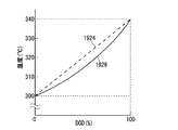
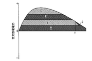
- FIG. 4 is a diagram illustrating an example of information describing the relationship between the DOD and temperature of the NaS battery 1004 at the time of discharging referred to by the ranking unit 1212.
- the discharge power of 1.0 MW, 0.8 MW, and 0.6 MW is discharged from the initial state where the DOD is 0% and the temperature is 300 ° C.
- Changes in DOD and temperature are shown in DOD-temperature characteristic lines 1912, 1914 and 1916, respectively.
- the ranking unit 1212 refers to the reference information describing the relationship between the DOD of the NaS battery 1004 and the temperature shown in FIG. 4, for example, the measured value Tm of the temperature is 300 ° C., and the calculated value DODm of the DOD is 0%. If the discharge power is 0.6 MW or less, the temperature is maintained at the upper limit temperature of 340 ° C. or lower and continuous discharge is possible until the DOD reaches 100%, that is, the second upper limit value U2m is set to 0. It can be seen from the DOD-temperature characteristic line 1916 that it should be 6 MW. Also, if the measured value Tm of the temperature is 305 ° C.
- the temperature is maintained at the upper limit temperature of 340 ° C. or less and the DOD is reduced to 100% if the emission power is 0.8 MW or less It can be seen from the DOD-temperature characteristic line 1918 that continuous discharge is possible until it reaches, that is, the second upper limit value U2m should be 0.8 MW.
- the DOD-temperature characteristic line from the initial state where the temperature is the measured value Tm and the DOD is the calculated value DODm to the final state where the temperature is below the upper limit temperature and the DOD is 100% is specified and specified.
- the discharge power that changes the temperature and DOD of the NaS battery 1004 along the DOD-temperature characteristic line the discharge power can be continuously discharged until the temperature is kept below the upper limit temperature and the DOD reaches 100%.
- An upper limit value U2m of 2 is specified.
- the upper limit value U2m of 2 is made to coincide with the first upper limit value U1m.
- the temperature of the NaS battery 1004 is maintained between the lower limit temperature and the upper limit temperature, and the DOD of the NaS battery 1004 is between 0% and 100%.
- the “upper limit temperature” is determined by the NaS battery 1004. It is desirable to set it lower than the maximum temperature at which it operates normally.
- the second upper limit value U2m having high accuracy is calculated even with a linear DOD-temperature characteristic line 1924 that roughly follows the change in the state of the NaS battery 1004.
- the second upper limit value U2m having higher accuracy is calculated.
- a DOD-temperature characteristic line 1926 shown in FIG. 5 has a bow shape in which the rate of change of temperature with respect to DOD is low immediately after the initial state. The rate of change in temperature relative to DOD immediately after the initial state is affected by the heat capacity and thermal resistance of the NaS battery 1004.
- the maximum value of the discharge power that can be continuously discharged until the DOD reaches 100% may be set as the second upper limit value U2m.
- the charge prioritization index ICm and the discharge prioritization index IDm include the calculated value IPm of the integrated charge / discharge power calculated by the integrated charge / discharge power calculation unit 1206 in the third term as a second subfactor.
- the coefficient CC of the third term of the charge prioritization index ICm and the coefficient CD of the third term of the discharge prioritization index IDm take negative values. Thereby, the charge priority and the discharge priority increase as the calculated value IPm of the integrated charge / discharge power decreases.
- charging power and discharging power are preferentially assigned to the NaS battery 1004 having a small accumulated charging / discharging power, so that the accumulating charging / discharging power of the NaS battery 1004 becomes uniform, and the deterioration of the NaS battery 1004 becomes uniform.
- the calculated value of the integrated charge / discharge current is replaced with the charge prioritization index ICm and the discharge instead of the calculated value IPm of the integrated charge / discharge power.
- Charging power and discharging power are preferentially assigned to the NaS battery 1004 that is included as a second sub-factor in the priority index IDm and has a low integrated charge / discharge current. More generally, the amount reflecting the usage history calculated by the usage history reflection amount calculation unit is included as the second sub-factor in the charge prioritization index ICm and the discharge prioritization index IDm, and the usage history is small. Charge power and discharge power are preferentially assigned to the NaS battery 1004.
- the charge prioritization index ICm and the discharge prioritization index IDm include the determination result of the necessity determination unit 1208 as the third factor in the fourth term,
- the detection result of the end-of-charge / end-of-discharge detection unit 1210 is included in the fourth term as a fourth factor.
- the coefficient DC of the fourth term of the charge prioritization index ICm takes a negative value
- the coefficient DD of the fourth term of the discharge prioritization index IDm takes a positive value, and indicates the state of correction of the calculated value of the discharge capacity.
- the expressed value Sm changes from 0 to ⁇ 1 when the necessity determining unit 1208 determines that the calculation value of the discharge capacity at the end of charging is necessary, and the charging end / discharge end detecting unit 1210 returns to the end of charging.
- -1 is changed to 1 when the arrival is detected, and is changed from 1 to 0 when the SOC approaches the target value SOCt.
- the necessity determination unit 1208 determines that the calculation value of the discharge capacity at the end of charging is required to be corrected, the charging priority is increased and the discharging priority is decreased.
- the end of charge / discharge end detection unit 1210 detects the end of charge, the charge priority is lowered and the discharge priority is raised.
- charging power is preferentially assigned to the NaS battery 1004 that requires correction of the calculated value of the discharge capacity at the end of charging, and preferentially discharged to the NaS battery 1004 that does not require correction of the calculated value of the discharge capacity at the end of charging. Since electric power is allocated, the calculation value of the discharge capacity at the end of charging is quickly corrected. Further, since the charging power is preferentially assigned to the NaS battery 1004 that has not reached the end of charging, and the discharging power is preferentially assigned to the NaS battery 1004 that has reached the end of charging, the calculated value of the discharge capacity at the end of charging is calculated. It becomes easy to bring the SOC close to the target value after the correction.
- the necessity determination unit 1208 determines that correction of the calculated value of discharge capacity at the end of discharge is necessary, the charge priority is lowered and the discharge priority is raised. Should. In addition, when the end of charge / end of discharge detection unit 1210 detects arrival of the end of discharge, the charge priority should be raised and the discharge priority should be lowered. For this reason, the coefficient DC of the fourth term of the charge prioritization index ICm takes a positive value, the coefficient DD of the fourth term of the discharge prioritization index IDm takes a negative value, and the calculation value of the discharge capacity is corrected.
- the value changes from -1 to 1, and when the SOC approaches the target value SOCt, the value changes from 1 to 0.
- charging power is preferentially assigned to the NaS battery 1004 that does not require correction of the calculated value of the discharge capacity at the end of discharge, and preferentially discharged to the NaS battery 1004 that requires correction of the calculated value of the discharge capacity at the end of discharge. Since electric power is allocated, the calculation value of the discharge capacity at the end of the discharge is quickly corrected.
- the charging power is preferentially assigned to the NaS battery 1004 that has reached the end of discharge
- the discharging power is preferentially assigned to the NaS battery 1004 that has not reached the end of discharge, after correcting the calculated value of the discharge capacity In this case, it is easy to bring the SOC close to the target value.
- the absolute values of the coefficients AC, BC, CC, and DC indicate the magnitude of the contribution of the main factor, the first subfactor, the second subfactor, the third and fourth subfactors to the charging priority, respectively.
- the absolute values of the coefficients AD, BD, CD, and DD are the magnitudes of contribution of the main factor, the first sub-factor, the second sub-factor, the third and fourth sub-factors to the charging priority, respectively. Indicates. When the charging priority is increased as the charging priority index ICm decreases, the signs of the coefficients AC, BC, CC, and DC are reversed, and when the discharging priority is increased as the discharge priority index IDm decreases, the coefficient AD , BD, CD, DD are inverted.
- the charge prioritization index ICm shown in Expression (1) and the discharge prioritization index IDm shown in Expression (3) are examples, and are changed according to the specifications of the power storage device 1002. In particular, it is naturally planned to delete all or part of the first to third subfactors and to add subfactors other than the first to third subfactors.
- the charge prioritization index ICm and the discharge prioritization index IDm may be shared.
- the power allocating unit 1214 sequentially allocates charging power from the NaS battery 1004 with a high charging priority assigned by the ranking unit 1212 to the NaS battery 1004 with a low charging priority, and the NaS battery 1004 with a high discharging priority assigned by the ranking unit 1212. To the lower NaS battery 1004 in order. In assigning the charging power to each of the plurality of NaS batteries 1004, if the unassigned charging power is greater than the maximum charging power of the NaS battery 1004, the maximum charging power is assigned, and the unassigned charging power is assigned to the NaS battery 1004. If the charging power is equal to or less than the maximum charging power of the NaS battery 1004, all of the unassigned charging power is allocated.
- the unassigned discharge power is larger than the maximum discharge power of the NaS battery 1004, the maximum discharge power is assigned, and the unassigned discharge power is If the maximum discharge power of the NaS battery 1004 is equal to or less than the maximum discharge power of the NaS battery 1004, all of the unassigned discharge power is allocated.
- the charging priority is 1 MW that is the same as the maximum charging power for the first NaS battery 1004. Charging power is allocated, the remaining charging power of 0.5 MW is allocated to the NaS battery 1004 with the second charging priority, and charging power is not allocated to the third and fourth NaS batteries 1004 with the charging priority. .
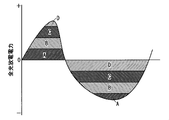
- FIG. 6 is a graph for explaining the reflection of charging priority and discharging priority on allocation of charging power and discharging power.
- FIG. 7 is a graph for explaining the reflection of the charging priority order to the allocation of charging power.
- time is plotted on the horizontal axis and total charge / discharge power is plotted on the vertical axis.
- Positive total charge / discharge power represents total charge power
- negative charge / discharge power represents total discharge power.
- the charging power and the discharging power allocated to the NaS batteries A, B, C, and D are represented by their own hatching.
- the charge / discharge command unit 1216 instructs the bidirectional converter 1012 to charge / discharge the charge / discharge power allocated by the power allocation unit 1214.
- the charge / discharge command unit 1216 determines that the necessity determination unit 1208 determines that the calculation value of the discharge capacity needs to be corrected until the charge end or the end of discharge at which the calculation value of the discharge capacity is corrected.
- a command for charging / discharging is output to bidirectional converter 1012.
- charge / discharge command unit 1216 controls the stop and restart of the operation of the bidirectional converter 1012.
- FIG. 8 is a graph showing the relationship between the discharge depth of NaS battery 1004 and the voltage.
- Correction of the calculated value of the discharge capacity is performed in a state where the NaS battery 1004 is charged until the end of charging, or in a state where the NaS battery 1004 is discharged until the end of discharge (the depth of discharge included in one phase region). Is called.
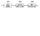
- the mode of operation of the power storage device 1002 is broadly divided into pattern operation and power smoothing operation.
- the pattern operation is an operation in which charging / discharging is performed in accordance with fluctuations in the daily power demand.
- pattern operation is generally performed in which charging is performed at night when power demand is low and discharging is performed during the day when power demand is low.
- charge / discharge power for each time is often set in advance.
- Power smoothing operation is an operation that performs charging and discharging according to shorter fluctuations in power demand.
- the SOC target value SOCt is often set to about 50%.
- the SOC target value SOCt is temporarily set near 100% when the calculated value of the discharge capacity of the NaS battery 1004 is corrected at the end of charging, and the NaS battery When the calculated value of the discharge capacity of 1004 is corrected at the end of the discharge, it is temporarily set near 0%.
- Allocation of charging power and discharging power to each of the plurality of NaS batteries 1004 may be performed manually.
- the power storage device 1002 displays the discharging priority order and the charging priority order on the display unit 1115, and operates the input of the charging power and discharging power allocation. Accepted by the unit 1020. In addition to the discharge priority and the charge priority, a recommended charge power and discharge power allocation may be displayed on the display unit 1115.
- the charging power and discharging power received by the operation unit 1020 are sent to the charge / discharge command unit 1236.
- the second embodiment relates to a category determination unit 2004, an intra-segment ranking unit 2006, and a power allocation unit 2008 that are employed instead of the ranking unit 1212 and the power allocation unit 1214 of the first embodiment.
- the main difference between the first embodiment and the second embodiment is the mode of determining the charging priority and discharging priority of the NaS battery 1004.
- the intra-category prioritization index Km is reflected in the intra-category charge priority and the intra-category discharge priority of the NaS battery 1004. Further, charging power is assigned in order from the NaS battery 1004 having a higher charge priority category to the lower NaS battery 1004, and discharging power is assigned in order from the NaS battery 1004 having a higher discharge priority category to the lower NaS battery 1004. Further, for the NaS batteries 1004 having the same charge priority category, the charge power is assigned in order from the NaS battery 1004 having the highest in-category charge priority to the lower NaS battery 1004, and for the NaS batteries 1004 having the same discharge priority category. Discharge power is assigned in order from the NaS battery 1004 having the highest internal discharge priority to the NaS battery 1004 having the lower priority.
- “Charge priority” and “discharge priority” in the first embodiment are “charge priority” and “discharge priority”, respectively.
- two or more NaS batteries 1004 are provided. The same “charging priority” and “discharging priority” are not given repeatedly.
- “charge priority” and “discharge priority” in the second embodiment are “charge priority category” and “discharge priority category”, respectively.
- two or more units are used. The NaS battery 1004 may overlap and belong to the same “charge priority category” and “discharge priority category”.
- a classification determination unit 2004 that determines a charge priority category and a discharge priority category to which the NaS battery 1004 belongs, and a NaS battery for each charge priority category and discharge priority category.
- An intra-segment ranking unit 2006 that assigns the intra-category charge priority and intra-category discharge priority to 1004, and a power allocation unit 2006 that allocates charge power and discharge power to the NaS battery 1004 are provided.
- the division determination unit 2004 stratifies the plurality of NaS batteries 1004 by reflecting the classification determination index Jm shown in Expression (6), and determines the charge priority category and the discharge priority category to which each of the plurality of NaS batteries 1004 belongs. .
- the category determination unit 2004 increases the charge priority category and decreases the discharge priority category as the category determination index Jm increases.
- ⁇ SOCm SOCt ⁇ SOCm with respect to the calculated value SOCm of the SOC calculated by the SOC calculation unit 1204 of the SOC target value SOCt as a main factor.
- the classification determination index Jm may include the same subfactor as the subfactor included in the charge prioritization index ICm and the discharge prioritization index IDm of the first embodiment. However, in this case, as described in the column of “Commonization of Charging Prioritization Index ICm and Discharge Prioritization Index IDm” in the first embodiment, the index for setting the charging priority and the discharge priority are set. It may be necessary to separate the index for attaching.
- FIG. 10 is a diagram illustrating the charging priority classification according to the second embodiment.
- the plurality of charge priority categories are classified according to the threshold value of the category determination index Jm. For example, when there are three charging priority categories, as shown in FIG. 10, the threshold TH12 for dividing the first charging priority category and the second charging priority category is set to 20%, and the second charging priority level is set.
- the threshold TH23 that separates the section from the third charge priority section is set to ⁇ 20%.
- the NaS battery 1004 with ⁇ SOCm ⁇ 20% belongs to the first charge priority category
- the NaS battery 1004 with 20% ⁇ ⁇ SOCm ⁇ ⁇ 20% belongs to the second charge priority category
- ⁇ 20% ⁇ ⁇ SOCm NaS battery 1004 belongs to the third charge priority category.
- the discharge priority category is also classified by the threshold value of the category determination index Jm.
- the intra-sector ranking unit 2006 reflects the intra-sector ranking index Km shown in Equation (7), assigns an intra-sector priority to each of the NaS batteries 1004 for each charge priority category, and sets the priority for each discharge priority category. Each NaS battery 1004 is given an intra-section discharge priority.
- the intra-segment ranking unit 2006 increases the intra-segment charging priority and the intra-segment discharge priority as the intra-segment ranking index Km decreases.
- the intra-section ranking index Km includes the calculated value IPm of the integrated charge / discharge power calculated by the integrated charge / discharge power calculation unit 1206 as a first factor. Thereby, the charge priority and the discharge priority increase as the calculated value IPm of the integrated charge / discharge power decreases. As a result, charging power and discharging power are preferentially assigned to the NaS battery 1004 with low accumulated charging / discharging power, so that the integrated charging / discharging power of the NaS battery 1004 becomes uniform, and the deterioration of the NaS battery 1004 becomes uniform.
- the amount reflecting the usage history such as the cumulative charging / discharging current instead of the cumulative charging / discharging power is included as the first factor in the in-category ranking index Km, and the charging power and discharging are preferentially applied to the NaS battery 1004 with a small usage history. Electric power may be allocated.
- the intra-segment ranking index Km is an index different from the intra-segment ranking index Jm, and the factor included in the intra-segment ranking index Km and the factor included in the intra-segment determination index Jm do not overlap. Accordingly, the intra-category ranking index Km different from the intra-segment determination index Jm is reflected in the intra-category priority and intra-category discharge priority, so that charging power and discharging power are more appropriately assigned.
- the intra-category ranking index Km is replaced with the first factor or in addition to the first factor, the following second to fourth These factors may be included, or factors other than the following second to fourth factors may be included.
- an index and an intra-category index for assigning an intra-category charge priority may be necessary to separate the index for setting the discharge priority.
- the intra-segment ranking index Km may include the temperature measurement value Tm measured by the temperature sensor 1010 as the second factor, and the intra-segment ranking unit 2006 increases the temperature measurement value Tm.
- the charging priority may be raised and the intra-segment discharge priority may be lowered.
- the intra-category ranking index Km includes the determination result of the necessity determining unit 1208 as a factor, and the intra-category ranking unit 2006 uses the necessity determining unit 1208 to determine the end of charging.
- the in-category charge priority may be raised and the in-category discharge priority may be lowered.
- the intra-category ranking index Km includes the detection result of the end-of-charge / discharge end detecting unit 1210 as a factor, and the intra-category ranking unit 2006 determines the end of charging /
- the in-category charge priority may be lowered and the in-category discharge priority may be raised.
- the intra-segment ranking unit 2006 lowers the intra-segment charging priority as the temperature measurement value Tm increases.
- the intra-segment ranking unit 2006 determines that the correction of the calculated value of the discharge capacity at the end of the discharge is necessary by the necessity determination unit 1208. Lower priority and increase discharge priority within category.
- the intra-segment ranking unit 2006 increases the intra-segment charge priority when the end of discharge is detected by the end of charge / end of discharge detection unit 1210. Lower the discharge priority within the category.
- the factor included in the intra-category ranking index Km brings the same effect as that included in the charge prioritization index ICm and the discharge prioritization index IDm of the first embodiment.
- the power allocation unit 2008 allocates charging power in order from the NaS battery 1004 having the higher charge priority category to which it belongs, determined by the category determination unit 2004, to the lower NaS battery 1004, and the discharge priority category to which the category determination unit 2004 belongs is assigned. Discharge power is allocated in order from the high NaS battery 1004 to the low NaS battery 1004. Further, the power allocation unit 2008 assigns the charging power in order from the NaS battery 1004 with the highest intra-segment charge priority assigned by the intra-segment ranking unit 2006 to the lower NaS battery 1004 for the NaS batteries 1004 with the same charge priority category. For the NaS batteries 1004 with the same assigned discharge priority category, the discharge power is assigned in order from the NaS battery 1004 with the highest intra-category discharge priority assigned by the intra-segment ranking unit 2006 to the lower NaS battery 1004.
- the third embodiment relates to the ranking of the intra-category charge priority and the intra-category discharge priority adopted instead of the intra-category charge priority and the intra-category discharge priority of the second embodiment.
- FIG. 11 is a diagram for explaining the prioritization of in-category charging priority according to the third embodiment.
- FIG. 11 shows the in-section charging priority of the NaS batteries 1, 2,..., N when the time has elapsed as T1, T2, T3, T4,.
- the intra-category charging priority is cyclically switched over time.
- the ranking of the discharge priority within the category is performed in the same manner.
- the fourth embodiment relates to ranking of charging priority and discharging priority employed instead of ranking of charging priority and discharging priority of the first embodiment.
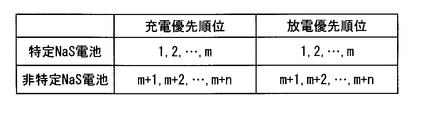
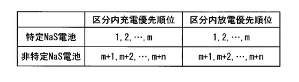
- FIG. 12 is a diagram for explaining the order of charge priority and discharge priority according to the fourth embodiment.
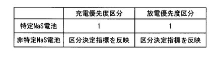
- FIG. 12 shows the charge priority and discharge of m specific NaS batteries 1004 (hereinafter referred to as “specific NaS batteries”) and NaS batteries 1004 other than the specific NaS batteries (hereinafter referred to as “non-specific NaS batteries”). Indicates the priority order.
- the highest charging priority and discharging priority are assigned to the specific NaS battery. That is, the first to mth charging priorities and discharging priorities are assigned to specific NaS batteries, and the (m + 1) th to m + nth charging priorities and discharging priorities are assigned to non-specific NaS batteries.
- charge power and discharge power are preferentially assigned to the specific NaS battery, so that the deteriorated NaS battery 1004 concentrates on the specific NaS battery, and maintenance becomes easy.
- the charge priority and the discharge priority assigned to the specific NaS battery may be fixed, but the charge priority index ICm and the discharge priority index IDm may be reflected, or when time passes. You may make it replace
- the non-specific NaS battery is given a charge priority and a discharge priority by reflecting the charge prioritization index ICm and the discharge prioritization index IDm.
- the specific NaS battery may be a NaS battery 1004 selected in advance. However, if the NaS battery 1004 in which a failure has occurred in the cell is a specific NaS battery, the NaS battery 1004 in which the failure has occurred in the constituent cells will deteriorate. Concentration and easy maintenance.
- the fifth embodiment relates to determination of a charge priority category and a discharge priority category employed instead of the determination of the discharge priority category and the charge priority category of the second embodiment.
- FIG. 13 is a diagram for explaining determination of the charge priority category and the discharge priority category of the fifth embodiment.
- FIG. 13 shows charge priority categories and discharge priority categories of m specific specific NaS batteries and n non-specific NaS batteries.
- the discharge priority category to which the specific NaS battery belongs and the first discharge priority category having the highest charge priority category. And the charging priority category.
- charge power and discharge power are preferentially assigned to the specific NaS battery, so that the deteriorated NaS battery 1004 concentrates on the specific NaS battery, and maintenance becomes easy.
- the intra-category charge priority and intra-category discharge priority assigned to a specific NaS battery may be fixed, but the intra-category ranking index Km may be reflected, and cyclically as time passes. You may make it replace.
- the discharge priority classification and the charge priority classification to which the non-specific NaS battery belongs are determined by reflecting the classification determination index Jm as in the second embodiment, and the non-specific NaS battery is classified in the same category as in the second embodiment. Reflecting the ranking index Km, the intra-category charge priority and the intra-category discharge priority are assigned.
- the sixth embodiment relates to the ranking of the intra-category charge priority and the intra-category discharge priority employed instead of the intra-category charge priority and the intra-category discharge priority of the second embodiment.
- FIG. 14 is a diagram illustrating the ranking of the in-category charge priority and the in-category discharge priority in the sixth embodiment.
- FIG. 14 shows the intra-category charge priority and intra-category discharge priority of m specific NaS batteries and n non-specific NaS batteries belonging to one charge priority category and discharge priority category.
- the highest intra-segment charge priority and intra-segment discharge priority are assigned to the specific NaS battery. That is, the first to mth intra-section charge priority and intra-section discharge priority are assigned to the specific NaS battery, and the m + 1-th to m + n-th intra-section charge priority and intra-section discharge priority are non-specific NaS batteries. It is attached to. Thereby, charge power and discharge power are preferentially assigned to the specific NaS battery, so that the deteriorated NaS battery 1004 concentrates on the specific NaS battery, and maintenance becomes easy.
- the intra-category charge priority and intra-category discharge priority assigned to a specific NaS battery may be fixed, but the intra-category ranking index Km may be reflected, and cyclically as time passes. You may make it replace.
- the non-specific NaS battery is given an intra-category charge priority and an intra-category discharge priority reflecting the intra-category ranking index Km.
- the charging priority assigned to the charging power allocation and the charging priority assigned to the discharging power assigned in the first embodiment are replaced with the charging priority assigned charging power allocation.
- the present invention relates to reflection and reflection of allocation of discharge priority to discharge power.
- FIG. 15 is a graph for explaining the reflection of the charging priority of the seventh embodiment on the allocation of charging power.
- time is plotted on the horizontal axis and total charge / discharge power is plotted on the vertical axis.
- Positive total charge / discharge power represents charge power
- negative charge / discharge power represents discharge power.
- charging power assigned to the NaS batteries A, B, C, and D is represented by hatching specific to each.
- the charging priority assigned to the charging power allocation and the charging priority assigned to the discharging power assigned in the first embodiment are replaced with the charging priority assigned charging power allocation.
- the present invention relates to reflection and reflection of allocation of discharge priority to discharge power.
- FIG. 16 is a graph for explaining the reflection of the charging priority of the eighth embodiment on the allocation of charging power.
- time is plotted on the horizontal axis and total charge / discharge power is plotted on the vertical axis.
- Positive total charge / discharge power represents charge power
- negative charge / discharge power represents discharge power.
- the charging power assigned to the NaS batteries A, B, C, and D is represented by hatching specific to each.
- the ninth embodiment relates to a charge priority category and a discharge priority category adopted instead of the charge priority category and the discharge priority category of the second embodiment.
- FIG. 17 is a diagram for explaining the charging priority classification according to the ninth embodiment.
- the plurality of charge priority categories are divided by the threshold value of the category determination index Jm.
- the threshold for lowering the charge priority category is shifted to the lower charge priority than the threshold for increasing the charge priority category, and the discharge priority category is lower than the threshold for increasing the discharge priority category. Is shifted to a lower discharge priority. Thereby, the inconvenience resulting from the frequent change of the charge priority category and the discharge priority category is suppressed.
- the threshold TH12U when raising the charge priority category from the second to the first is set to 21%, and the charge priority from the first to the second.
- the threshold value TH12D for lowering the classification is set to 19%.
- the threshold TH23U when lowering the charging priority classification from the third to the second is set to -19%, and the threshold value raising the charging priority classification from the second to the third is set to -21%.
- the tenth embodiment relates to a power storage network 10002.
- the power storage network 10002 of the tenth embodiment is provided with a control device that controls charging / discharging of a plurality of charging / discharging units.
- the plurality of control devices constitutes a hierarchical control device network, and information necessary for determining an index or an index, a maximum charge power, and a maximum discharge power are notified from the lower level control device to the higher level control device.
- the lower control device is notified of the allocation of charging power and discharging power.
- the “charge / discharge unit” is a unit for performing charge / discharge independently, and may mean a power storage device including a control device, or may refer to a NaS battery itself that does not include a control device.
- FIG. 18 is a block diagram of the power storage network 10002 of the tenth embodiment.
- charging / discharging of the plurality of NaS batteries 10004 is controlled by the control device 10006, and charging / discharging of the plurality of NaS batteries 10008 is controlled by the control device 10010.
- the plurality of NaS batteries 10004 and the control device 10006 constitute a charge / discharge unit 10012
- the plurality of NaS batteries 10008 and the control device 10010 also constitute a charge / discharge unit 10014.
- Charging / discharging of the NaS battery 10016 which comprises a charging / discharging unit by charging / discharging unit 10012 and 10014 and itself is controlled by the control apparatus 10018.
- the charge / discharge units 10012 and 10014, the NaS battery 10016, and the control device 10018 constitute a larger charge / discharge unit 10020.
- charging / discharging of the plurality of NaS batteries 10022 is controlled by the control device 10024.
- the plurality of NaS batteries 10022 and the control device 10024 constitute a charge / discharge unit 10026.
- Charging / discharging of the NaS battery 10022 which constitutes charging / discharging unit by itself and charging / discharging unit 10026 is controlled by the control apparatus 10030.
- the charge / discharge unit 10026, the NaS battery 1000028, and the control device 10030 constitute a larger charge / discharge unit 10032.
- Charging / discharging of the charging / discharging units 10020, 10032 is controlled by the control device 10034.
- the control devices 10006, 10010, 10018, 10024, 10030, and 10034 regard the charging / discharging unit as a NaS battery, and the control device of the first embodiment or the control device of the first embodiment is the second embodiment to the tenth embodiment.
- the charge / discharge of the charge / discharge unit is controlled in the same manner as in the control device to which the modification described above is added.
- the number of NaS batteries and control devices provided in the power storage network 10002 is increased or decreased according to the specifications of the power storage network 10002, and the number of layers in the control device network is increased or decreased according to the specifications of the power storage network 10002.
- FIG. 19 is a block diagram of the lower order control device 10102 included in the first charge / discharge unit whose charge / discharge is controlled by the higher order control device 10104 and the higher order control device 10104 that controls the charge / discharge of the plurality of first charge / discharge units. is there.
- the control device 10006 serves as the lower control device 10102
- the control device 10018 serves as the higher control device 10104
- the charge / discharge units 10012 and 10014 and the NaS battery 10016 serve as the first charge / discharge unit.
- the upper control apparatus 10104 includes a communication unit 10106 that communicates with the lower control apparatus 10102, a power allocation determination unit 10108 that determines allocation of charge power and discharge power to the first charge / discharge unit, Is provided.
- the communication unit 10106 transmits the assigned charging power and discharging power to the lower-level control device 10102, and information necessary for specifying an index or an index reflected in the charging priority and the discharging priority from the lower-level control device 10102.
- the maximum charge power and the maximum discharge power are received. “Information necessary for specifying an index” includes, for example, factors included in the index.
- the power allocation determining unit 10108 regards the first charging / discharging unit as a NaS battery, reflects the index received from the communication unit 10106 or the information necessary to identify the index, and reflects the first charging / discharging unit.
- the charge priority and the discharge priority of the discharge unit are determined, the charge power is assigned in order from the first charge / discharge unit having the highest charge priority to the first charge / discharge unit having the lower charge priority, and the charge priority is decreased from the charge / discharge unit having the higher discharge priority.
- Discharge power is allocated to charge / discharge units in order.
- the lower-level control apparatus 10102 determines the power allocation determination that determines the allocation of the charging power and the discharge power to the communication unit 10110 that communicates with the higher-level control apparatus 10104 and the second charge / discharge unit whose charging / discharging is controlled by the lower-level control apparatus 10102 Unit 10112.
- the communication unit 10110 receives the assigned charging power and discharging power from the host controller 10104, and transmits information necessary for specifying the index or the index, the maximum charging power and the maximum discharging power to the host controller 10104.
- the maximum charging power transmitted by the communication unit 10110 is the sum of the maximum charging powers of each of the plurality of second charging / discharging units, and the maximum discharging power transmitted by the communication unit 10110 is the plurality of second charging / discharging units. It is the sum of each maximum discharge power.
- the power allocation unit 10112 divides the allocated charging power and discharging power received by the communication unit 10102 and allocates them to the second charging / discharging unit.
- the eleventh embodiment relates to a microgrid 11004 including a power storage device 11002.
- FIG. 20 is a block diagram of the microgrid 11004 of the eleventh embodiment.
- a “microgrid” is a small-scale power supply network in which a distributed power source is installed in a place where power is demanded, and is also called a “distributed energy system” or the like.
- a distributed power source 11006 As shown in FIG. 20, in the microgrid 11004, a distributed power source 11006, a load 11008, and a power storage device 11002 are connected to the system 11010. The operation of the distributed power source 11006, the load 11008, and the power storage device 11002 is controlled by the microgrid control system 11012.
- the distributed power source 11006 is not particularly limited, but a generator using sunlight or other natural energy, for example, a solar power generator is used.
- a fuel cell or the like that uses, as a fuel, a gas produced using raw garbage, waste wood, waste plastic, or the like as a raw material may be used as the distributed power source 11006.
- All or part of the power generated by the distributed power source 11006 is transmitted to the power storage device 11002 via the system 11010 and accumulated in the power storage device 11002.
- the power storage device 1002 according to the first embodiment or the power storage device obtained by adding the modifications described in the second to ninth embodiments to the power storage device 1002 according to the first embodiment is employed.
Abstract
Disclosed are a controller, a controller network and a charging/discharging control method which facilitate bringing the SOC (state of charge) of a secondary battery close to a target value. A rank index including as the main factor the difference (ΔSOCm = SOCt - SOCm) between the target value (SOCt) of the SOC and the calculated value (SOCm) of the SOC is influenced by the charging priority rank and discharging priority rank of an NaS battery. Furthermore, charging power is allocated in order from NaS batteries having a high charging priority rank to NaS batteries having a low charging priority rank, and discharging power is allocated in order from NaS batteries having a high discharging priority rank to NaS batteries having a low discharging priority rank.
Description
本発明は、複数の二次電池の充放電を制御する制御装置、複数の充放電単位の充放電を制御する制御装置を複数備える制御装置網及び複数の二次電池の充放電を制御する制御方法に関する。
The present invention relates to a control device that controls charging / discharging of a plurality of secondary batteries, a control device network that includes a plurality of control devices that control charging / discharging of a plurality of charging / discharging units, and a control that controls charging / discharging of a plurality of secondary batteries. Regarding the method.
特許文献1は、複数の二次電池の充放電の制御に関する。特許文献1は、複数の二次電池(二次電池モジュール7a,7b)に充電優先順位及び放電優先順位をつけること(段落0090等)、充電優先順位が高い二次電池から低い二次電池へ順に充電電力を割り当て放電優先順位が高い二次電池から低い二次電池へ順に放電電力を割り当てること(段落0107)、内部抵抗と相関がある量に応じて充放電電力を調整すること(段落0080等)等に言及している。
Patent Document 1 relates to charge / discharge control of a plurality of secondary batteries. In Patent Document 1, a plurality of secondary batteries (secondary battery modules 7a and 7b) are given a charge priority and a discharge priority (paragraph 0090, etc.), and a secondary battery having a high charge priority is changed to a secondary battery having a low charge priority. The charging power is assigned in order, the discharging power is assigned in order from the secondary battery having the highest discharge priority to the lower secondary battery (paragraph 0107), and the charging / discharging power is adjusted according to the amount correlated with the internal resistance (paragraph 0080). Etc.).
しかし、特許文献1の複数の二次電池の充放電の制御では、複数の二次電池につけられる充電優先順位及び放電優先順位は固定されている(段落0090等)。
However, in the charge / discharge control of the plurality of secondary batteries in Patent Document 1, the charge priority and the discharge priority assigned to the plurality of secondary batteries are fixed (paragraph 0090 and the like).
一方、複数の二次電池を備える電力貯蔵装置においては、複数の二次電池のSOC(充電状態)を目標値に近づけたい場合がある。例えば、電力貯蔵装置が電力平滑運転を行う場合、SOCの目標値は、約50%に設定されることが多い。また、SOCの目標値は、二次電池の放電容量の演算値を充電末において補正するときは、一時的に100%付近に設定され、二次電池の放電容量の演算値を放電末において補正するときは、一時的に0%の付近に設定される。
On the other hand, in a power storage device including a plurality of secondary batteries, there are cases where the SOC (charged state) of the plurality of secondary batteries is desired to approach a target value. For example, when the power storage device performs power smoothing operation, the target value of SOC is often set to about 50%. In addition, when the calculated value of the discharge capacity of the secondary battery is corrected at the end of charging, the target value of SOC is temporarily set near 100%, and the calculated value of the discharge capacity of the secondary battery is corrected at the end of discharging. When this is done, it is temporarily set near 0%.
しかし、特許文献1等の従来の複数の二次電池の充放電の制御では、二次電池のSOCを目標値に近づけることが難しい場合がある。
However, in the conventional charge / discharge control of a plurality of secondary batteries such as Patent Document 1, it may be difficult to bring the SOC of the secondary battery close to the target value.
本発明は、この問題を解決するためになされたもので、二次電池のSOCを目標値に近づけることが容易な制御装置、制御装置網及び制御方法を提供することを目的とする。
The present invention has been made to solve this problem, and an object of the present invention is to provide a control device, a control device network, and a control method that can easily bring the SOC of a secondary battery close to a target value.
上記の課題を解決するための手段を以下に説明する。
Measures for solving the above problems will be described below.
第1の発明は、複数の二次電池の充放電を制御する制御装置であって、複数の二次電池の各々の充放電電流を計測する充放電電流計測部と、充放電電力が指令値となるように複数の二次電池の各々の充放電を制御する双方向変換器と、前記充放電電流計測部により計測された充放電電流の計測値を積算し複数の二次電池の各々の放電容量を演算する放電容量演算部と、前記放電容量演算部により演算された放電容量の演算値から複数の二次電池の各々の充電状態を演算する充電状態演算部と、第1の指標を反映させて複数の二次電池の各々の充電優先度及び放電優先度を決定する優先度決定部と、前記優先度決定部により決定された充電優先度が高い二次電池から低い二次電池へ順に充電電力を割り当て、前記優先度決定部により決定された放電優先度が高い二次電池から低い二次電池へ順に放電電力を割り当てる電力割り当て部と、前記電力割り当て部により割り当てられた充放電電力の充放電を前記双方向変換器に指令する充放電司令部と、を備え、第1の指標は、前記充電状態演算部により演算された充電状態の演算値に対する充電状態の目標値の差、を因子として含み、前記優先度決定部は、前記充電状態演算部により演算された充電状態の演算値に対する充電状態の目標値の差が大きくなるほど充電優先度を上げ放電優先度を下げる。
1st invention is a control apparatus which controls charging / discharging of a some secondary battery, Comprising: The charging / discharging electric current measurement part which measures each charging / discharging current of several secondary battery, and charging / discharging electric power are command values A bi-directional converter that controls charging / discharging of each of the plurality of secondary batteries so that the charging / discharging current measurement values measured by the charging / discharging current measuring unit are integrated to each of the plurality of secondary batteries. A discharge capacity calculation unit for calculating a discharge capacity, a charge state calculation unit for calculating the charge state of each of the plurality of secondary batteries from the calculated value of the discharge capacity calculated by the discharge capacity calculation unit, and a first index A priority determining unit that reflects and determines the charging priority and discharging priority of each of the plurality of secondary batteries, and from a secondary battery having a high charging priority determined by the priority determining unit to a low secondary battery Charging power is allocated in order and determined by the priority determination unit. A power allocation unit that sequentially allocates discharge power from a secondary battery having a high discharge priority to a secondary battery having a low discharge priority, and a charge / discharge commander that instructs the bidirectional converter to charge / discharge the charge / discharge power allocated by the power allocation unit And the first indicator includes, as a factor, a difference in the target value of the charge state with respect to the calculated value of the charge state calculated by the charge state calculation unit, and the priority determination unit includes the charge state The charging priority is increased and the discharging priority is decreased as the difference between the charging state target value calculated by the calculating unit and the charging state target value increases.
第2の発明は、第1の発明の制御装置において、複数の二次電池の各々の温度を計測する温度センサ、をさらに備え、複数の二次電池は、放電すると発熱反応が発生する二次電池であり、第1の指標は、前記温度センサにより計測された温度の計測値、を因子として含み、前記優先度決定部は、前記温度センサにより計測された温度の計測値が高くなるほど放電優先度を下げる。
According to a second aspect of the present invention, the control device of the first aspect further includes a temperature sensor that measures the temperature of each of the plurality of secondary batteries, and the plurality of secondary batteries generate secondary reactions that generate an exothermic reaction when discharged. The battery is a battery, and the first index includes a measured value of the temperature measured by the temperature sensor as a factor, and the priority determination unit is configured to prioritize discharge as the measured value of the temperature measured by the temperature sensor increases. Decrease the degree.
第3の発明は、第1の発明の制御装置において、複数の二次電池の各々の温度を計測する温度センサ、をさらに備え、複数の二次電池は、充電すると発熱反応が発生する二次電池であり、第1の指標は、前記温度センサにより計測された温度の計測値、を因子として含み、前記優先度決定部は、前記温度センサにより計測された温度の計測値が高くなるほど充電優先度を下げる。
According to a third aspect of the present invention, in the control device of the first aspect of the present invention, the control device further includes a temperature sensor that measures the temperature of each of the plurality of secondary batteries. The battery is a battery, and the first index includes a measured value of the temperature measured by the temperature sensor as a factor, and the priority determining unit prioritizes charging as the measured value of the temperature measured by the temperature sensor increases. Decrease the degree.
第4の発明は、第1の発明の制御装置において、前記電力割り当て部は、複数の二次電池の各々に第1の上限値以下の放電電力を割り当て、前記制御装置は、複数の二次電池の各々の温度を計測する温度センサと、複数の二次電池の各々について前記温度センサにより計測された温度の計測値及び前記放電容量演算部により演算された放電容量の演算値から温度が上限温度以下に維持される放電電力の第2の上限値を演算する上限値演算部と、をさらに備え、前記第1の指標は、前記上限値演算部により演算された第2の上限値の第1の上限値に対する比を因子として含み、前記優先度決定部は、前記上限値演算部により演算された第2の上限値の第1の上限値に対する比が大きくなるほど放電優先度を上げる。
According to a fourth aspect of the present invention, in the control device according to the first aspect, the power allocation unit allocates a discharge power equal to or lower than a first upper limit value to each of the plurality of secondary batteries, and the control device includes a plurality of secondary batteries. The temperature is an upper limit based on a temperature sensor that measures the temperature of each of the batteries, a measured value of the temperature measured by the temperature sensor for each of the plurality of secondary batteries, and a calculated value of the discharge capacity calculated by the discharge capacity calculating unit. An upper limit value calculating unit that calculates a second upper limit value of the discharge power maintained below the temperature, wherein the first index is the second upper limit value calculated by the upper limit value calculating unit. A ratio of 1 to the upper limit value is included as a factor, and the priority determination unit increases the discharge priority as the ratio of the second upper limit value calculated by the upper limit value calculation unit to the first upper limit value increases.
第5の発明は、第1ないし第4のいずれかの発明の制御装置において、複数の二次電池の各々について充電末における放電容量の演算値の補正の要否を判定する要否判定部、をさらに備え、第1の指標は、前記要否判定部の判定結果、を因子として含み、前記優先度決定部は、前記要否判定部により充電末における放電容量の演算値の補正が必要であると判定されると充電優先度を上げ放電優先度を下げる。
5th invention is the control apparatus of any one of the 1st thru | or 4th invention, the necessity determination part which determines the necessity of correction | amendment of the calculation value of the discharge capacity in the end of charge about each of several secondary batteries, The first index includes the determination result of the necessity determination unit as a factor, and the priority determination unit needs to correct the calculation value of the discharge capacity at the end of charging by the necessity determination unit. If it is determined that there is, the charging priority is raised and the discharging priority is lowered.
第6の発明は、第1ないし第4のいずれかの発明の制御装置において、複数の二次電池の各々について放電末における放電容量の演算値の補正の要否を判定する要否判定部、をさらに備え、第1の指標は、前記要否判定部の判定結果、を因子として含み、前記優先度決定部は、前記要否判定部により放電末における放電容量の演算値の補正が必要であると判定されると充電優先度を下げ放電優先度を上げる。
6th invention is the control apparatus of any one of the 1st thru | or 4th invention, the necessity determination part which determines the necessity of correction | amendment of the calculation value of the discharge capacity at the end of discharge about each of several secondary batteries, The first index includes the determination result of the necessity determination unit as a factor, and the priority determination unit needs to correct the calculation value of the discharge capacity at the end of discharge by the necessity determination unit. If it is determined that there is, the charge priority is lowered and the discharge priority is raised.
第7の発明は、第1ないし第6のいずれかの発明の制御装置において、複数の二次電池の各々について放電容量の演算値の補正が行われる充電末への到達を検出する充電末検出部、をさらに備え、第1の指標は、前記充電末検出部の検出結果、を因子として含み、前記優先度決定部は、前記充電末検出部により充電末への到達が検出されると充電優先度を下げ放電優先度を上げる。
According to a seventh invention, in the control device of any one of the first to sixth inventions, an end-of-charge detection for detecting the arrival at the end of charge in which the calculated value of the discharge capacity is corrected for each of the plurality of secondary batteries. The first index includes a detection result of the end-of-charge detection unit as a factor, and the priority determination unit is charged when reaching the end of charge is detected by the end-of-charge detection unit. Lower priority and increase discharge priority.
第8の発明は、第1ないし第6のいずれかの発明の制御装置において、複数の二次電池の各々について放電容量の演算値の補正が行われる放電末への到達を検出する放電末検出部、を備え、第1の指標は、前記放電末検出部の検出結果、をさらに因子として含み、前記優先度決定部は、前記放電末検出部により放電末への到達が検出されると充電優先度を上げ放電優先度を下げる。
According to an eighth aspect of the present invention, in the control device according to any one of the first to sixth aspects of the present invention, a discharge end detection for detecting the arrival at the end of the discharge in which the calculated value of the discharge capacity is corrected for each of the plurality of secondary batteries. The first index further includes the detection result of the discharge end detection unit as a factor, and the priority determination unit is charged when arrival at the discharge end is detected by the discharge end detection unit. Increase priority and decrease discharge priority.
第9の発明は、第1ないし第8のいずれかの発明の制御装置において、複数の二次電池の各々の使用の履歴を反映する量を演算する使用履歴反映量演算部、をさらに備え、第1の指標は、前記使用履歴反映量演算部により演算された使用の履歴を反映する量、を因子として含み、前記優先度決定部は、使用の履歴が少なくなるほど充電優先度及び放電優先度を上げる。
According to a ninth aspect of the present invention, the control device according to any one of the first to eighth aspects further includes a usage history reflection amount calculation unit that calculates an amount reflecting the usage history of each of the plurality of secondary batteries. The first index includes, as a factor, an amount reflecting the usage history calculated by the usage history reflection amount calculation unit, and the priority determination unit determines the charge priority and the discharge priority as the usage history decreases. Raise.
第10の発明は、第1の発明の制御装置において、前記優先度決定部は、第1の指標を反映させて複数の二次電池の各々に充電優先順位及び放電優先順位をつける順位づけ部、を備え、前記電力割り当て部は、前記順位づけ部によりつけられた充電優先順位が高い二次電池から低い二次電池へ順に充電電力を割り当て、前記順位づけ部によりつけられた放電優先順位が高い二次電池から低い二次電池へ順に放電電力を割り当てる。
According to a tenth aspect of the present invention, in the control device according to the first aspect, the priority determining unit ranks a charging priority and a discharge priority for each of the plurality of secondary batteries by reflecting the first index. The power allocating unit allocates charging power in order from a secondary battery having a higher charge priority assigned by the ranking unit to a secondary battery having a lower priority, and the discharge priority given by the ranking unit is Discharge power is allocated in order from the higher secondary battery to the lower secondary battery.
第11の発明は、第1の発明の制御装置において、前記優先度決定部は、第1の指標により複数の二次電池を層別し複数の二次電池の各々が属する充電優先度区分及び放電優先度区分を決定する区分決定部、を備え、前記制御装置は、第1の指標とは異なる第2の指標を反映させて、充電優先度区分ごとに二次電池の各々に区分内充電優先順位をつけ、放電優先度区分ごとに二次電池の各々に区分内放電優先順位をつける区分内順位づけ部、をさらに備え、前記電力割り当て部は、前記区分決定部により決定された属する充電優先度区分が高い二次電池から低い二次電池へ順に充電電力を割り当て、前記区分決定部により決定された属する放電優先度区分が高い二次電池から低い二次電池へ順に放電電力を割り当て、属する充電優先度区分が同じ二次電池については前記区分内順位づけ部によりつけられた区分内充電優先順位が高い二次電池から低い二次電池へ順に充電電力を割り当て、属する放電優先度区分が同じ二次電池については前記区分内順位づけ部によりつけられた区分内放電優先順位が高い二次電池から低い二次電池へ順に放電電力を割り当てる。
According to an eleventh aspect of the present invention, in the control device according to the first aspect, the priority determination unit stratifies a plurality of secondary batteries according to a first index, and includes a charge priority classification to which each of the plurality of secondary batteries belongs. A classification determination unit that determines a discharge priority classification, and the control device reflects a second index different from the first index, and charges each secondary battery for each charging priority classification An intra-category ranking unit for assigning priorities and assigning intra-category discharge priorities to each of the secondary batteries for each discharge priority category, wherein the power allocating unit is assigned to the charge determined by the category determining unit. Assign charging power in order from a secondary battery having a high priority classification to a secondary battery having a low priority classification, and assigning discharging power in order from a secondary battery having a higher priority classification to which the discharge priority classification determined by the classification determination unit belongs to, Charge priority category For the same secondary battery, the charging power is assigned in order from the secondary battery having the highest charging priority within the category set by the ranking unit to the secondary battery having the lower priority, and for the secondary battery having the same discharge priority category. Discharge power is allocated in order from a secondary battery having a higher intra-section discharge priority set by the intra-section ranking unit to a lower secondary battery.
第12の発明は、第11の発明の制御装置において、複数の二次電池の各々の温度を計測する温度センサ、をさらに備え、複数の二次電池は、充電すると吸熱反応が発生し放電すると発熱反応が発生する二次電池であり、第2の指標は、前記温度センサにより計測された温度の計測値、を因子として含み、前記区分内順位づけ部は、前記温度センサにより計測された温度の計測値が高くなるほど区分内放電優先度を下げる。
A twelfth aspect of the invention is the control device of the eleventh aspect of the invention, further comprising a temperature sensor that measures the temperature of each of the plurality of secondary batteries. When the plurality of secondary batteries are charged, an endothermic reaction occurs and discharges. A secondary battery in which an exothermic reaction occurs, the second index includes a measured value of the temperature measured by the temperature sensor as a factor, and the intra-category ranking unit includes a temperature measured by the temperature sensor The higher the measured value, the lower the discharge priority within the category.
第13の発明は、第11の発明の制御装置において、複数の二次電池の各々の温度を計測する温度センサ、をさらに備え、複数の二次電池は、充電すると発熱反応が発生し放電すると吸熱反応が発生する二次電池であり、第2の指標は、前記温度センサにより計測された温度の計測値、を因子として含み、前記区分内順位づけ部は、前記温度センサにより計測された温度の計測値が高くなるほど区分内充電優先度順位を下げる。
A thirteenth aspect of the invention is the control device of the eleventh aspect of the invention, further comprising a temperature sensor that measures the temperature of each of the plurality of secondary batteries. When the plurality of secondary batteries are charged, an exothermic reaction occurs and discharges. It is a secondary battery in which an endothermic reaction occurs, the second index includes a measured value of the temperature measured by the temperature sensor as a factor, and the intra-category ranking unit includes a temperature measured by the temperature sensor The higher the measured value, the lower the in-category charge priority order.
第14の発明は、第11ないし第13のいずれかの発明の制御装置において、複数の二次電池の各々について充電末における放電容量の演算値の補正の要否を判定する要否判定部、をさらに備え、第2の指標は、前記要否判定部の判定結果、を因子として含み、前記区分内順位づけ部は、前記要否判定部により充電末における放電容量の演算値の補正が必要であると判定されると区分内充電優先順位を上げ区分内放電優先順位を下げる。
In a fourteenth aspect of the present invention, in the control device of any of the eleventh to thirteenth aspects, a necessity determination unit that determines whether or not the correction of the calculated value of the discharge capacity at the end of charging is necessary for each of the plurality of secondary batteries. The second index includes the determination result of the necessity determination unit as a factor, and the intra-category ranking unit needs to correct the calculation value of the discharge capacity at the end of charging by the necessity determination unit If it is determined, the intra-category charge priority is raised and the intra-category discharge priority is lowered.
第15の発明は、第11ないし第13のいずれかの発明の制御装置において、複数の二次電池の各々について放電末における放電容量の演算値の補正の要否を判定する要否判定部、をさらに備え、第2の指標は、前記要否判定部の判定結果、を因子として含み、前記区分内順位づけ部は、前記要否判定部により放電末における放電容量の演算値の補正が必要であると判定されると区分内充電優先順位を下げ区分内放電優先順位を上げる。
A fifteenth aspect of the control device according to any one of the eleventh to thirteenth aspects of the present invention is a necessity determination unit that determines whether or not correction of the calculated value of discharge capacity at the end of discharge is necessary for each of the plurality of secondary batteries. The second index includes the determination result of the necessity determination unit as a factor, and the intra-segment ranking unit needs to correct the calculation value of the discharge capacity at the end of discharge by the necessity determination unit. If it is determined, the intra-category charge priority is lowered and the intra-category discharge priority is raised.
第16の発明は、第11ないし第15のいずれかの発明の制御装置において、複数の二次電池の各々について放電容量の演算値の補正が行われる充電末への到達を検知する充電末検出部、をさらに備え、第2の指標は、前記充電末検出部の検出結果、を因子として含み、前記区分内順位づけ部は、前記充電末検出部により充電末への到達が検知されると区分内充電優先順位を下げ区分内放電優先順位を上げる。
According to a sixteenth aspect of the present invention, in the control device according to any one of the eleventh to fifteenth aspects of the present invention, the end of charge detection for detecting the arrival of the end of charge in which the calculated value of the discharge capacity is corrected for each of the plurality of secondary batteries A second index includes a detection result of the end-of-charge detection unit as a factor, and the intra-section ranking unit detects that the end of charge is detected by the end-of-charge detection unit Lower the charge priority within the category and raise the discharge priority within the category.
第17の発明は、第11ないし第15のいずれかの発明の制御装置において、複数の二次電池の各々について放電容量の演算値の補正が行われる放電末への到達を検知する放電末検出部、をさらに備え、第2の指標は、前記充電末検出部の検出結果、を因子として含み、前記区分内順位づけ部は、前記充電末検出部により放電末への到達が検知されると区分内充電優先順位を上げ区分内放電優先順位を下げる。
According to a seventeenth aspect of the present invention, in the control device according to any one of the eleventh to fifteenth aspects, a discharge end detection for detecting the arrival at the end of the discharge in which the calculated value of the discharge capacity is corrected for each of the plurality of secondary batteries. The second index includes a detection result of the end-of-charge detection unit as a factor, and the intra-section ranking unit detects that the end of discharge is detected by the end-of-charge detection unit Raise the in-category charge priority and lower the in-category discharge priority.
第18の発明は、第11ないし第17のいずれかの発明の制御装置において、複数の二次電池の各々の使用の履歴を反映する量を演算する使用履歴反映量演算部、をさらに備え、第2の指標は、前記使用履歴反映量演算部により演算された使用の履歴を反映する量、を因子として含み、前記優先度決定部は、使用の履歴が少なくなるほど充電優先度及び放電優先度を上げる。
According to an eighteenth aspect of the present invention, the control device according to any one of the eleventh to seventeenth aspects further includes a usage history reflection amount calculation unit that calculates an amount reflecting the usage history of each of the plurality of secondary batteries, The second index includes, as a factor, an amount that reflects the usage history calculated by the usage history reflection amount calculation unit, and the priority determination unit determines the charge priority and the discharge priority as the usage history decreases. Raise.
第19の発明は、第11ないし第18のいずれかの発明の制御装置において、前記区分内順位づけ部は、複数の二次電池のうちの特定の二次電池に最も高い区分内充電優先順位及び区分内放電優先順位をつける。
According to a nineteenth aspect of the present invention, in the control device according to any one of the eleventh to eighteenth aspects, the intra-segment ranking unit has the highest intra-category charge priority for a specific secondary battery among a plurality of secondary batteries. And prioritize intra-segment discharge.
第20の発明は、第1の発明の制御装置において、前記優先度決定部は、第1の指標により複数の二次電池を層別し複数の二次電池の各々が属する充電優先度区分及び放電優先度区分を決定する区分決定部、を備え、前記制御装置は、充電優先度区分ごとに二次電池の各々に充電優先順位をつけ、時間が経過すると充電優先順位を循環的に入れ替え、放電優先度区分ごとに二次電池の各々に放電の優先順位をつけ、時間が経過すると放電優先順位を循環的に入れ替える区分内順位づけ部、をさらに備え、前記電力割り当て部は、前記区分決定部により決定された属する充電優先度区分が高い二次電池から低い二次電池へ順に充電電力を割り当て、前記区分決定部により決定された属する放電優先度区分が高い二次電池から低い二次度へ順に放電電力を割り当て、属する充電優先度区分が同じ二次電池については前記区分内順位づけ部によりつけられた区分内充電優先順位が高い二次電池から低い二次電池へ順に充電電力を割り当て、属する放電優先度区分が同じ二次電池については前記区分内順位づけ部によりつけられた区分内放電優先順位が高い二次電池から低い二次電池へ順に放電電力を割り当てる。
According to a twentieth aspect, in the control device according to the first aspect, the priority determination unit stratifies a plurality of secondary batteries according to the first index, and includes a charge priority classification to which each of the plurality of secondary batteries belongs. A determination unit for determining a discharge priority category, the control device assigns a charge priority to each of the secondary batteries for each charge priority category, and cyclically replaces the charge priority as time elapses, And further comprising: an intra-segment ranking unit that prioritizes discharge for each secondary battery for each discharge priority segment and cyclically replaces the discharge priorities when time elapses, wherein the power allocation unit determines the segment The charging power is assigned in order from the secondary battery having the higher charge priority category determined by the unit to the secondary battery having the lower priority, and the secondary battery having the higher discharge priority category determined by the category determining unit is assigned from the lower secondary battery. In order For secondary batteries with the same charge priority category to which they belong, charge power is assigned in order from the secondary battery with the highest in-category charge priority assigned by the intra-category ranking unit to the lower secondary battery. For secondary batteries having the same discharge priority category, discharge power is assigned in order from a secondary battery having a higher intra-category discharge priority set by the intra-category ranking unit to a lower secondary battery.
第21の発明は、第11ないし第20のいずれかの発明の制御装置において、前記区分決定部が充電優先度区分を上げるときの第1の指標の閾値よりも前記区分決定部が充電優先度区分を下げるときの第1の指標の閾値の方が充電優先度が低い方向にずらされている。
According to a twenty-first aspect, in the control device according to any one of the eleventh to twentieth aspects, the classification determining unit has a charging priority higher than a threshold value of a first index when the classification determining unit increases the charging priority classification. The threshold value of the first index when lowering the classification is shifted in the direction of lower charge priority.
第22の発明は、第1ないし第21のいずれかの発明の制御装置において、前記電力割り当て部は、前記優先度決定部により決定された充電優先度の変化により第1の二次電池から第2の二次電池への充電電力の割り当て先の変更が必要になった場合、全充電電力の減少により第1の二次電池への充電電力の割り当てがなくなった後に充電優先度の変化を充電電力の割り当てに反映させ、前記優先度決定部により決定された放電優先度の変化により第1の二次電池から第2の二次電池への放電電力の割り当て先の変更が必要になった場合、全放電電力の減少により第1の二次電池への放電電力の割り当てがなくなった後に放電優先度の変化を放電電力の割り当てに反映させる。
According to a twenty-second invention, in the control device according to any one of the first to twenty-first inventions, the power allocation unit is configured to change from the first secondary battery according to a change in charge priority determined by the priority determination unit. When it is necessary to change the allocation destination of the charging power to the secondary battery of No. 2, the change in the charging priority is charged after the charging power is no longer allocated to the first secondary battery due to the decrease in the total charging power. When it is necessary to change the allocation destination of the discharge power from the first secondary battery to the second secondary battery due to the change in the discharge priority determined by the priority determination unit, which is reflected in the power allocation Then, after the discharge power is no longer assigned to the first secondary battery due to the decrease in the total discharge power, the change in the discharge priority is reflected in the discharge power assignment.
第23の発明は、第1ないし第22のいずれかの発明の制御装置において、前記電力割り当て部は、前記優先度決定部により決定された充電優先度の変化により第1の二次電池から第2の二次電池への充電電力の割り当て先の変更が必要になった場合、第1の二次電池から第2の二次電池へ充電電力の割り当て先を少しずつ変更し、前記優先度決定部により決定された放電優先度の変化により第1の二次電池から第2の二次電池への放電電力の割り当て先の変更が必要になった場合、第1の二次電池から第2の二次電池へ放電電力の割り当て先を少しずつ変更する。
According to a twenty-third aspect of the present invention, in the control device according to any one of the first to twenty-second aspects, the power allocating unit changes from the first secondary battery according to a change in the charging priority determined by the priority determining unit. When it is necessary to change the allocation destination of charging power to the secondary battery of No. 2, the allocation destination of charging power is gradually changed from the first secondary battery to the second secondary battery, and the priority is determined. When it is necessary to change the allocation destination of the discharge power from the first secondary battery to the second secondary battery due to the change in the discharge priority determined by the unit, the first secondary battery to the second Change the assignment destination of discharge power to the secondary battery little by little.
第24の発明は、第1ないし第23のいずれかの発明の制御装置において、前記優先度決定部は、複数の二次電池のうちの特定の二次電池の充電優先度及び放電優先度を最も高くする。
According to a twenty-fourth aspect of the present invention, in the control device according to any one of the first to twenty-third aspects, the priority determining unit determines a charge priority and a discharge priority of a specific secondary battery among a plurality of secondary batteries. Make it the highest.
第25の発明は、第1ないし第24のいずれかの発明の制御装置において、前記充放電司令部は、前記電力割り当て部により充電電力又は放電電力が割り当てられていない二次電池の充放電を制御する双方向変換器の全部又は一部の運転を停止させる。
According to a twenty-fifth aspect of the invention, in the control device according to any one of the first to twenty-fourth aspects, the charge / discharge command unit charges / discharges a secondary battery to which charge power or discharge power is not allocated by the power allocation unit. Stop the operation of all or part of the bidirectional converter to be controlled.
第26の発明は、第25の発明の制御装置において、前記充放電司令部は、前記電力割り当て部により充電電力又は放電電力が割り当てられていない二次電池のうちの充電優先度又は放電優先度が最も高い二次電池の充放電を制御する双方向変換器以外の双方向変換器の運転を停止させる。
In a control device according to a twenty-sixth aspect, in the control device according to the twenty-fifth aspect, the charge / discharge command unit is a charge priority or a discharge priority among secondary batteries to which charge power or discharge power is not allocated by the power allocation unit. The operation of the bidirectional converter other than the bidirectional converter that controls charging / discharging of the secondary battery having the highest value is stopped.
第27の発明は、第25の発明の制御装置において、前記充放電司令部は、前記電力割り当て部により充電電力又は放電電力が割り当てられていない二次電池のうちの充電優先度又は放電優先度が最も高い二次電池の充放電を制御する双方向変換器の運転を停止させ新たに充電電力又は放電電力が割り当てられる前に運転を再開させる。
In a control device according to a twenty-seventh aspect, in the control device according to the twenty-fifth aspect, the charge / discharge command unit is a charge priority or a discharge priority among secondary batteries to which charge power or discharge power is not allocated by the power allocation unit. The operation of the bidirectional converter that controls charging / discharging of the secondary battery having the highest value is stopped, and the operation is restarted before new charging power or discharging power is allocated.
第28の発明は、複数の充放電単位の充放電を制御する制御装置を複数備える制御装置網であって、複数の第1の充放電単位の充放電を制御する上位制御装置と、前記第1の充放電単位の各々の全部又は一部に備えられ第2の充放電単位の充放電を制御する下位制御装置と、を備え、前記上位制御装置は、前記下位制御装置と通信し、割り当てた充電電力及び放電電力を前記下位制御装置へ送信し、前記下位制御装置から、充電優先度及び放電優先度に反映される指標又は指標を特定するために必要な情報を受信する第1の通信部と、前記第1の通信部により受信された指標又は指標を特定するために必要な情報から特定した指標を反映させて第1の充放電単位の充電優先度及び放電優先度を決定し、充電優先度が高い第1の充放電単位から低い第1の充放電単位へ順に充電電力を割り当て、放電優先度が高い充放電単位から低い充放電単位へ順に放電電力を割り当てる電力割り当て決定部と、を備え、前記下位制御装置は、前記上位制御装置と通信し、割り当てられた充電電力及び放電電力を前記上位制御装置から受信し、上位制御装置へ指標又は指標を特定するために必要な情報を送信する第2の通信部、を備え、指標は、充電状態の演算値に対する充電状態の目標値の差、を因子として含み、前記電力割り当て部は、充電状態の演算値に対する充電状態の目標値の差が大きくなるほど充電優先度を上げ放電優先度を下げる。
A twenty-eighth aspect of the present invention is a control device network including a plurality of control devices that control charging / discharging of a plurality of charging / discharging units, the host control device controlling charging / discharging of a plurality of first charging / discharging units, A low-order control device that controls charge / discharge of the second charge / discharge unit provided in all or part of each of the charge / discharge units, and the high-order control device communicates with and assigns the low-order control device 1st communication which transmits information required in order to identify the parameter | index or parameter | index reflected in charging priority and discharge priority from the said low-order control apparatus, and transmitting the charging power and discharge power which were measured to the said low-order control apparatus The charging priority and the discharging priority of the first charging / discharging unit are determined by reflecting the index specified from the information necessary for specifying the index or the index received by the first communication unit or the index, Is it the first charge / discharge unit with high charge priority? A power allocation determining unit that sequentially allocates charging power to a low first charging / discharging unit, and sequentially allocates discharging power from a charging / discharging unit with a high discharging priority to a charging / discharging unit with a low discharging priority. A second communication unit that communicates with the control device, receives the allocated charging power and discharging power from the host control device, and transmits information necessary for specifying the index or the index to the host control device, The indicator includes, as a factor, a difference in a target value of the charge state with respect to a calculated value of the charge state, and the power allocation unit increases the charging priority as the difference in the target value of the charge state with respect to the calculated value of the charge state increases. Decrease priority.
第29の発明は、複数の二次電池の充放電を制御する制御方法であって、(a) 複数の二次電池の各々の充放電電流を計測する工程と、(b) 前記工程(a)において計測された充放電電流の計測値を積算し複数の二次電池の各々の放電容量を演算する工程と、(c) 前記工程(b)において演算された放電容量の演算値から複数の二次電池の各々の充電状態を演算する工程と、(d) 第1の指標を反映させて複数の二次電池の各々の充電優先度及び放電優先度を決定する工程と、(e) 前記工程(d)において決定された充電優先度が高い二次電池から低い二次電池へ順に充電電力を割り当て、前記工程(d)において決定された放電優先度が高い二次電池から低い二次電池へ順に放電電力を割り当てる工程と、(f) 前記工程(e)において割り当てられた充放電電力の充放電を指令する工程と、(g) 充放電電力が前記工程(g)において指令された指令値となるように複数の二次電池の各々の充放電を制御する工程と、を備え、第1の指標は、前記工程(c)において演算された充電状態の演算値に対する充電状態の目標値の差、を因子として含み、前記工程(d)は、前記工程(c)において演算された充電状態の演算値に対する充電状態の目標値の差が大きくなるほど充電優先度を上げ放電優先度を下げる。
A twenty-ninth aspect of the invention is a control method for controlling charging / discharging of a plurality of secondary batteries, wherein (a) a step of measuring charging / discharging currents of each of the plurality of secondary batteries, and (b) the step (a ) Calculating the discharge capacity of each of the plurality of secondary batteries by accumulating the measured values of the charge / discharge current measured in step (b), and (c) calculating the discharge capacity calculated in step (b) above. Calculating a charge state of each secondary battery; (d) determining a charge priority and a discharge priority of each of the plurality of secondary batteries reflecting the first index; and (e) The charging power is assigned in order from the secondary battery having a high charge priority determined in the step (d) to the secondary battery having a low charge priority, and the secondary battery having the high discharge priority determined in the step (d) is low to the secondary battery. (F) 電力 charge / discharge power allocated in step (e) And (g) controlling charging / discharging of each of the plurality of secondary batteries so that the charging / discharging power becomes the command value commanded in the step (g), The index includes, as a factor, a difference between a target value of the charge state with respect to a calculated value of the charge state calculated in the step (c), and the step (d) includes the charge state calculated in the step (c). The charging priority is increased and the discharging priority is decreased as the difference between the calculated value and the target value of the charging state increases.
本発明によれば、充電状態の演算値が目標値を大きく下回る二次電池に優先的に充電電力が割り当てられ、充電状態の演算値が目標値を大きく上回る二次電池に優先的に放電電力が割り当てられるので、充電状態を目標値に近づけることが容易になる。
According to the present invention, the charging power is preferentially assigned to the secondary battery in which the calculated value of the charging state is significantly lower than the target value, and the discharging power is preferentially assigned to the secondary battery in which the calculated value of the charging state greatly exceeds the target value. Therefore, it becomes easy to bring the state of charge close to the target value.
第2ないし第3の発明によれば、温度が高いときに発熱反応の発生の頻度が少なくなるように二次電池が充放電され、二次電池の温度が安定する。
According to the second to third inventions, when the temperature is high, the secondary battery is charged and discharged so that the frequency of occurrence of the exothermic reaction is reduced, and the temperature of the secondary battery is stabilized.
第4の発明によれば、温度が上限温度に達するおそれが低い二次電池に優先的に放電電力が割り当てられるので、二次電池の温度が上限温度に達することが抑制される。
According to the fourth aspect of the invention, since the discharge power is preferentially assigned to the secondary battery whose temperature is unlikely to reach the upper limit temperature, the secondary battery temperature is suppressed from reaching the upper limit temperature.
第5の発明によれば、充電末における放電容量の演算値の補正が必要な二次電池に優先的に充電電力が割り当てられ、充電末における放電容量の演算値の補正が不要な二次電池に優先的に放電電力が割り当てられるので、充電末における放電容量の演算値の補正が迅速に行われる。
According to the fifth aspect of the invention, the secondary battery that preferentially allocates the charging power to the secondary battery that needs to correct the calculated value of the discharge capacity at the end of charging, and does not require the correction of the calculated value of the discharge capacity at the end of charging. Since the discharge power is preferentially assigned to the battery, the calculation value of the discharge capacity at the end of charging is corrected quickly.
第6の発明によれば、放電末における放電容量の演算値の補正が不要な二次電池に優先的に充電電力が割り当てられ、放電末における放電容量の演算値の補正が必要な二次電池に優先的に放電電力が割り当てられるので、放電末における放電容量の演算値の補正が迅速に行われる。
According to the sixth aspect of the invention, a secondary battery in which charge power is preferentially assigned to a secondary battery that does not require correction of the calculated value of the discharge capacity at the end of discharge, and the calculated value of the discharge capacity at the end of discharge is required. Since the discharge power is preferentially assigned to, correction of the calculated value of the discharge capacity at the end of discharge is performed quickly.
第7の発明によれば、充電末へ到達していない二次電池に優先的に充電電力が割り当てられ、充電末へ到達した二次電池に優先的に放電電力が割り当てられるので、放電容量の演算値の補正の後に充電状態を目標値に近づけることが容易になる。
According to the seventh invention, the charging power is preferentially assigned to the secondary battery that has not reached the end of charging, and the discharging power is preferentially assigned to the secondary battery that has reached the end of charging. It becomes easy to bring the state of charge close to the target value after the correction of the calculated value.
第8の発明によれば、放電末へ到達した二次電池に優先的に充電電力が割り当てられ、放電末へ到達していない二次電池に優先的に放電電力が割り当てられるので、放電容量の演算値の補正の後に充電状態を目標値に近づけることが容易になる。
According to the eighth aspect of the invention, charge power is preferentially assigned to the secondary battery that has reached the end of discharge, and discharge power is preferentially assigned to the secondary battery that has not reached the end of discharge. It becomes easy to bring the state of charge close to the target value after the correction of the calculated value.
第9の発明によれば、使用の履歴が少ない二次電池に優先的に充電電力及び放電電力が割り当てられるので、二次電池の使用の履歴が均一になり、二次電池の劣化が均一になり、複数の二次電池のいずれかに劣化に伴う故障が早期に発生することが防止される。
According to the ninth aspect, since the charging power and the discharging power are preferentially assigned to the secondary battery having a small usage history, the usage history of the secondary battery becomes uniform, and the deterioration of the secondary battery becomes uniform. Thus, it is possible to prevent a failure due to deterioration from occurring at an early stage in any of the plurality of secondary batteries.
第11の発明によれば、第1の指標がわずかに変化しても属する充電優先度区分及び放電優先度区分が変化しないことが多いので、充電優先度及び放電優先度の頻繁な変化に起因する不都合が抑制される。また、第1の指標とは異なる第2の指標が区分内充電優先順位及び区分内放電優先順位に反映されるので、充電電力及び放電電力がより適切に割り当てられる。
According to the eleventh aspect of the invention, the charge priority category and the discharge priority category to which the first indicator does not change even if the first index slightly changes often does not change, resulting in frequent changes in the charge priority and discharge priority. The inconvenience is suppressed. Moreover, since the 2nd parameter | index different from a 1st parameter | index is reflected in the charging priority in a division | segmentation and the discharge priority in a division | segmentation, charging power and discharge power are allocated more appropriately.
第12ないし第13の発明によれば、温度が高いときに発熱反応の発生の頻度が少なくなるように二次電池が充放電されるので、二次電池の温度が安定する。
According to the twelfth to thirteenth inventions, when the temperature is high, the secondary battery is charged / discharged so that the frequency of the exothermic reaction is reduced, so that the temperature of the secondary battery is stabilized.
第14の発明によれば、充電末における放電容量の演算値の補正が必要な二次電池に優先的に充電電力が割り当てられ、充電末における放電容量の演算値の補正が不要な二次電池に優先的に放電電力が割り当てられるので、充電末における放電容量の演算値の補正が迅速に行われる。
According to the fourteenth aspect of the invention, the secondary battery that preferentially allocates the charging power to the secondary battery that requires correction of the calculated value of the discharge capacity at the end of charging, and does not require correction of the calculated value of the discharge capacity at the end of charging. Since the discharge power is preferentially assigned to the battery, the calculation value of the discharge capacity at the end of charging is corrected quickly.
第15の発明によれば、放電末における放電容量の演算値の補正が不要な二次電池に優先的に充電電力が割り当てられ、放電末における放電容量の演算値の補正が必要な二次電池に優先的に放電電力が割り当てられるので、放電末における放電容量の演算値の補正が迅速に行われる。
According to the fifteenth aspect of the invention, a secondary battery in which charging power is preferentially assigned to a secondary battery that does not require correction of the calculated value of the discharge capacity at the end of the discharge, and the calculated value of the discharge capacity at the end of the discharge is required to be corrected. Since the discharge power is preferentially assigned to, correction of the calculated value of the discharge capacity at the end of discharge is performed quickly.
第16の発明によれば、放電容量の演算値の補正が行われる充電末へ到達していない二次電池に優先的に充電電力が割り当てられ、放電容量の演算値の補正が行われる充電末へ到達した二次電池に優先的に放電電力が割り当てられるので、放電容量の演算値の補正の後において充電状態を目標値に近づけることが容易になる。
According to the sixteenth aspect of the invention, the charging power is preferentially assigned to the secondary battery that has not reached the charging end where the calculation value of the discharge capacity is corrected, and the calculation value of the discharging capacity is corrected. Since the discharge power is preferentially assigned to the secondary battery that has reached, it becomes easy to bring the state of charge closer to the target value after correcting the calculated value of the discharge capacity.
第17の発明によれば、放電容量の演算値の補正が行われる放電末へ到達した二次電池に優先的に充電電力が割り当てられ、放電容量の演算値の補正が行われる放電末へ到達していない二次電池に優先的に放電電力が割り当てられるので、放電容量の演算値の補正の後において充電状態を目標値に近づけることが容易になる。
According to the seventeenth aspect of the invention, the charging power is preferentially assigned to the secondary battery that has reached the end of the discharge for which the calculation value of the discharge capacity is corrected, and the end of the discharge is performed for which the calculation value of the discharge capacity is corrected. Since the discharge power is preferentially assigned to the secondary battery that has not been performed, it becomes easy to bring the state of charge closer to the target value after correcting the calculated value of the discharge capacity.
第18の発明によれば、使用の履歴が少ない二次電池に優先的に充電電力及び放電電力が割り当てられるので、二次電池の使用の履歴が均一になり、二次電池の劣化が均一になり、複数の二次電池のいずれかに劣化に伴う故障が早期に発生することが防止される。
According to the eighteenth aspect, charge power and discharge power are preferentially assigned to a secondary battery with a small usage history, so the usage history of the secondary battery becomes uniform and the deterioration of the secondary battery becomes uniform. Thus, it is possible to prevent a failure due to deterioration from occurring at an early stage in any of the plurality of secondary batteries.
第19の発明によれば、特定の二次電池に優先的に充電電力及び放電電力が割り当てられるので、劣化する二次電池が特定の二次電池に集中し、保全が容易になる。
According to the nineteenth aspect, charge power and discharge power are preferentially assigned to a specific secondary battery, so that deteriorated secondary batteries are concentrated on the specific secondary battery, and maintenance is facilitated.
第20の発明によれば、第1の指標がわずかに変化しても属する充電優先度区分及び放電優先度区分が変化しないことが多いので、充電優先度及び放電優先度の頻繁な変化に起因する不都合が抑制される。また、二次電池の使用の履歴が均一になり、二次電池の劣化が均一になり、複数の二次電池のいずれかに劣化に伴う故障が早期に発生することが防止される。
According to the twentieth invention, the charge priority category and the discharge priority category to which the first index does not change even if the first index slightly changes often does not change, and thus is caused by frequent changes in the charge priority and the discharge priority. The inconvenience is suppressed. In addition, the usage history of the secondary battery becomes uniform, the deterioration of the secondary battery becomes uniform, and a failure due to the deterioration of any of the plurality of secondary batteries is prevented from occurring at an early stage.
第21の発明によれば、充電優先度及び放電優先度の頻繁な変化に起因する不都合が抑制される。
According to the twenty-first aspect, inconvenience due to frequent changes in charge priority and discharge priority is suppressed.
第22ないし第23の発明によれば、放電電力又は充電電力の割り当て又はその解消が急に行われることが抑制されるので、全充電電力又は全放電電力が安定する。
According to the twenty-second to twenty-third inventions, it is possible to suppress the sudden allocation of the discharge power or the charge power or the cancellation thereof, so that the total charge power or the total discharge power is stabilized.
第24の発明によれば、特定の二次電池に優先的に充電電力及び放電電力が割り当てられるので、劣化する二次電池が特定の二次電池に集中し、保全が容易になる。
According to the twenty-fourth aspect, charge power and discharge power are preferentially assigned to a specific secondary battery, so that deteriorated secondary batteries are concentrated on the specific secondary battery, and maintenance is facilitated.
第25の発明によれば、双方向変換器を待機させる電力が不要になり、双方向変換器の消費電力が減少する。
According to the twenty-fifth aspect, electric power for waiting the bidirectional converter becomes unnecessary, and the power consumption of the bidirectional converter is reduced.
第26ないし第27の発明によれば、双方向変換器を待機させる電力が減少するとともに、充電優先順位又は放電優先順位が最も高い二次電池への新たな充電電力又は放電電力の割り当てが迅速になる。
According to the twenty-sixth to twenty-seventh aspects, the power for waiting for the bidirectional converter is reduced, and the new charging power or discharging power is quickly assigned to the secondary battery having the highest charging priority or discharging priority. become.
第28の発明によれば、ひとつの制御装置が行う処理が減少するので、多数の二次電池の充放電の制御が容易になる。
According to the twenty-eighth aspect, since the processing performed by one control device is reduced, it is easy to control charging / discharging of a large number of secondary batteries.
これらの及びこれら以外の本発明の目的、特徴、局面及び利点は、添付図面とともに考慮されたときに下記の本発明の詳細な説明によってより明白となる。
These and other objects, features, aspects and advantages of the present invention will become more apparent from the following detailed description of the present invention when considered in conjunction with the accompanying drawings.
<1 第1実施形態>
(第1実施形態の概略)
第1実施形態は、電力貯蔵装置1002に関する。第1実施形態においては、SOC(充電状態)の目標値SOCtとSOCの演算値SOCmとの差ΔSOCm=SOCt-SOCmを主因子として含む順位づけ指標がNaS電池1004の充電優先順位及び放電優先順位に反映される。また、充電優先順位が高いNaS電池1004から低いNaS電池1004へ順に充電電力が割り当てられ、放電優先順位が高いNaS電池1004から低いNaS電池1004へ順に放電電力が割り当てられる。 <1 First Embodiment>
(Outline of the first embodiment)
The first embodiment relates to apower storage device 1002. In the first embodiment, the ranking index including a difference ΔSOCm = SOCt−SOCm as a main factor between the SOC (charge state) target value SOCt and the calculated value SOCm of the SOC is the charge priority and discharge priority of the NaS battery 1004. It is reflected in. Further, charging power is assigned in order from the NaS battery 1004 having a higher charge priority to the NaS battery 1004 having a lower priority, and the discharging power is assigned in order from the NaS battery 1004 having a higher discharge priority to the lower NaS battery 1004.
(第1実施形態の概略)
第1実施形態は、電力貯蔵装置1002に関する。第1実施形態においては、SOC(充電状態)の目標値SOCtとSOCの演算値SOCmとの差ΔSOCm=SOCt-SOCmを主因子として含む順位づけ指標がNaS電池1004の充電優先順位及び放電優先順位に反映される。また、充電優先順位が高いNaS電池1004から低いNaS電池1004へ順に充電電力が割り当てられ、放電優先順位が高いNaS電池1004から低いNaS電池1004へ順に放電電力が割り当てられる。 <1 First Embodiment>
(Outline of the first embodiment)
The first embodiment relates to a
(電力貯蔵装置1002の概略)
図1は、第1実施形態の電力貯蔵装置1002のブロック図である。 (Outline of power storage device 1002)
FIG. 1 is a block diagram of apower storage device 1002 according to the first embodiment.
図1は、第1実施形態の電力貯蔵装置1002のブロック図である。 (Outline of power storage device 1002)
FIG. 1 is a block diagram of a
図1に示すように、電力貯蔵装置1002は、電力を貯蔵するNaS電池1004と、系統1902とNaS電池1004とを接続する接続線1006と、NaS電池1004の充放電電流を計測する電流検出器1008と、NaS電池1004の温度を計測する温度センサ1010と、NaS電池1004から系統1902へ供給される電力を直流から交流へ変換し系統1902からNaS電池1004へ供給される電力を交流から直流へ変換する双方向変換器1012と、NaS電池1004から系統1902へ供給される電力を昇圧し系統1902からNaS電池1004へ供給される電力を降圧する変圧器1014と、電力貯蔵装置1002を制御する制御部1016と、情報を表示する表示部1018と、操作を受け付ける操作部1020と、を備える。
As shown in FIG. 1, the power storage device 1002 includes a NaS battery 1004 that stores power, a connection line 1006 that connects the system 1902 and the NaS battery 1004, and a current detector that measures the charge / discharge current of the NaS battery 1004. 1008, a temperature sensor 1010 for measuring the temperature of the NaS battery 1004, and power supplied from the NaS battery 1004 to the system 1902 is converted from direct current to alternating current, and power supplied from the system 1902 to the NaS battery 1004 is converted from alternating current to direct current. Bidirectional converter 1012 for conversion, transformer 1014 for boosting power supplied from NaS battery 1004 to system 1902 and reducing power supplied from system 1902 to NaS battery 1004, and control for controlling power storage device 1002 Unit 1016, display unit 1018 for displaying information, and operation for accepting an operation It includes a 1020, a.
接続線1006、電流検出器1008、温度センサ1010、双方向変換器1012及び変圧器1014は、複数のNaS電池1004の各々に対応して1個ずつ設けられ、電流検出器1008、双方向変換器1012及び変圧器1014は、接続線1006に挿入される。電流検出器1008は、双方向変換器1012の直流側に挿入され、変圧器1014は、双方向変換器1012の交流側に挿入される。
One connection line 1006, current detector 1008, temperature sensor 1010, bidirectional converter 1012, and transformer 1014 are provided corresponding to each of the plurality of NaS batteries 1004, and the current detector 1008, bidirectional converter 1012 and the transformer 1014 are inserted into the connection line 1006. The current detector 1008 is inserted on the DC side of the bidirectional converter 1012, and the transformer 1014 is inserted on the AC side of the bidirectional converter 1012.
4個のNaS電池1004の各々は、独立して充放電が可能な充放電単位をなす。図1には、4個のNaS電池1004が示されているが、NaS電池1004の数は電力貯蔵装置1002の仕様に応じて増減される。NaS電池1004に代えて他の種類の二次電池を採用してもよい。
Each of the four NaS batteries 1004 forms a charge / discharge unit that can be charged / discharged independently. Although four NaS batteries 1004 are shown in FIG. 1, the number of NaS batteries 1004 is increased or decreased according to the specifications of the power storage device 1002. Instead of the NaS battery 1004, other types of secondary batteries may be employed.
電流検出器1008、温度センサ1010、双方向変換器1012、変圧器1014、制御部1016、表示部1018及び操作部1020は、複数のNaS電池1004の充放電を制御する制御装置を構成する。制御部1016は、複数のNaS電池1004の全体としての充放電電力(以下では、「全充放電電力」という)が設定値となるように、複数のNaS電池1004の各々へ充電電力及び放電電力を割り当てる。全充放電電力の設定値は、操作部1020から入力される場合もあるし、電力貯蔵装置1002を備えるマイクログリッドのマイクログリッド制御システムから通信回線を経由して入力される場合もある。入力された充放電電力の入力値がそのまま設定値とならずに、電力貯蔵装置1002において消費される電力を確保することができるように設定値が設定される場合もある。
Current detector 1008, temperature sensor 1010, bidirectional converter 1012, transformer 1014, control unit 1016, display unit 1018, and operation unit 1020 constitute a control device that controls charging / discharging of a plurality of NaS batteries 1004. The control unit 1016 charges and discharges power to each of the plurality of NaS batteries 1004 so that the charge / discharge power as a whole of the plurality of NaS batteries 1004 (hereinafter referred to as “total charge / discharge power”) becomes a set value. Assign. The set value of the total charge / discharge power may be input from the operation unit 1020 or may be input from a microgrid control system of a microgrid provided with the power storage device 1002 via a communication line. The input value of the input charge / discharge power does not become the set value as it is, and the set value may be set so that the power consumed in the power storage device 1002 can be secured.
(NaS電池1004)
図2は、NaS電池1004のモジュール1102の回路図である。 (NaS battery 1004)
FIG. 2 is a circuit diagram of themodule 1102 of the NaS battery 1004.
図2は、NaS電池1004のモジュール1102の回路図である。 (NaS battery 1004)
FIG. 2 is a circuit diagram of the
図2に示すように、モジュール1102は、ブロック1104を直列接続した直列接続体であり、ブロック1104は、ストリング1106を並列接続した並列接続体であり、ストリング1106は、セル1108を直列接続した直列接続体である。ブロック1104の直列接続数、ストリング1106の並列接続数及びセル1108の直列接続数は、モジュール1102の仕様に応じて増減される。
As shown in FIG. 2, the module 1102 is a serial connection body in which blocks 1104 are connected in series, the block 1104 is a parallel connection body in which strings 1106 are connected in parallel, and the string 1106 is a series connection in which cells 1108 are connected in series. It is a connected body. The number of blocks 1104 connected in series, the number of strings 1106 connected in parallel, and the number of cells 1108 connected in series are increased or decreased according to the specifications of the module 1102.
NaS電池1004は、1個以上のモジュール1102を備える。モジュール1102の数は、NaS電池1004の仕様に応じて増減される。
The NaS battery 1004 includes one or more modules 1102. The number of modules 1102 is increased or decreased according to the specifications of the NaS battery 1004.
(電流検出器1008)
電流検出器1008は、複数のNaS電池1004の各々の充放電電流を計測する。充放電電力を直接的に計測するのではなく間接的に計測してもよい。例えば、充放電電力を計測し充放電電力の計測値を充放電電流に換算してもよい。充放電電力の計測値が充放電電流に換算される場合は、例えば、双方向変換器1012の交流側において交流充放電電力が計測され、双方向変換器1012の直流側において直流充放電電圧が計測され、交流充放電電力の計測値及び直流充放電電圧の計測値から充放電電流が算出される。 (Current detector 1008)
Thecurrent detector 1008 measures the charge / discharge current of each of the plurality of NaS batteries 1004. The charge / discharge power may be measured indirectly rather than directly. For example, charge / discharge power may be measured and the measured value of charge / discharge power may be converted into charge / discharge current. When the measured value of charge / discharge power is converted into charge / discharge current, for example, AC charge / discharge power is measured on the AC side of bidirectional converter 1012, and DC charge / discharge voltage is measured on the DC side of bidirectional converter 1012. The charge / discharge current is calculated from the measured value of AC charge / discharge power and the measured value of DC charge / discharge voltage.
電流検出器1008は、複数のNaS電池1004の各々の充放電電流を計測する。充放電電力を直接的に計測するのではなく間接的に計測してもよい。例えば、充放電電力を計測し充放電電力の計測値を充放電電流に換算してもよい。充放電電力の計測値が充放電電流に換算される場合は、例えば、双方向変換器1012の交流側において交流充放電電力が計測され、双方向変換器1012の直流側において直流充放電電圧が計測され、交流充放電電力の計測値及び直流充放電電圧の計測値から充放電電流が算出される。 (Current detector 1008)
The
(双方向変換器1012)
双方向変換器1012は、充放電の指令に従って複数のNaS電池1004の各々を充放電させ、充放電電力が指令値となるように複数のNaS電池1004の各々の充放電を制御する。 (Bidirectional converter 1012)
Bidirectional converter 1012 charges / discharges each of a plurality of NaS batteries 1004 according to a charge / discharge command, and controls charging / discharging of each of the plurality of NaS batteries 1004 so that charge / discharge power becomes a command value.
双方向変換器1012は、充放電の指令に従って複数のNaS電池1004の各々を充放電させ、充放電電力が指令値となるように複数のNaS電池1004の各々の充放電を制御する。 (Bidirectional converter 1012)
双方向変換器1012は、「PCS(Power Conversion System)」「交直変換器」等とも呼ばれる。双方向変換器1012における直流と交流との相互変換は、PWM(Pulse Width Modulation)インバータ等により行われる。
The bidirectional converter 1012 is also called “PCS (Power Conversion System)”, “AC / DC converter”, or the like. Mutual conversion between direct current and alternating current in the bidirectional converter 1012 is performed by a PWM (Pulse Width Modulation) inverter or the like.
(双方向変換器1012の運転の停止)
充電電力又は放電電力が割り当てられていないNaS電池1004(以下では、「未割り当てNaS電池」という)の充放電を制御する双方向変換器1012の運転を停止してよい。これにより、双方向変換器1012を待機させる電力が不要になり、制御装置の消費電力が減少する。 (Stop of operation of bidirectional converter 1012)
You may stop the operation | movement of the bidirectional | two-way converter 1012 which controls charging / discharging of the NaS battery 1004 (henceforth an "unallocated NaS battery") to which charging power or discharge power is not allocated. Thereby, the electric power which makes the bidirectional | two-way converter 1012 stand by becomes unnecessary, and the power consumption of a control apparatus reduces.
充電電力又は放電電力が割り当てられていないNaS電池1004(以下では、「未割り当てNaS電池」という)の充放電を制御する双方向変換器1012の運転を停止してよい。これにより、双方向変換器1012を待機させる電力が不要になり、制御装置の消費電力が減少する。 (Stop of operation of bidirectional converter 1012)
You may stop the operation | movement of the bidirectional | two-
双方向変換器1012の運転を停止する場合、未割り当てNaS電池の充放電を制御する双方向変換器112の全部の運転を停止してもよいが、未割り当てNaS電池のうちの充電優先順位又は放電優先順位が最も高いNaS電池1004の充放電を制御する双方向変換器1012以外の一部の双方向変換器1012を停止してもよい。これにより、充電優先順位又は放電優先順位が最も高いNaS電池1004への新たな充電電力又は放電電力の割り当てが迅速になる。
When stopping the operation of the bidirectional converter 1012, the entire operation of the bidirectional converter 112 that controls charging / discharging of the unassigned NaS battery may be stopped. Some bidirectional converters 1012 other than the bidirectional converter 1012 that controls charging / discharging of the NaS battery 1004 having the highest discharge priority may be stopped. This speeds up the assignment of new charging power or discharging power to the NaS battery 1004 having the highest charging priority or discharging priority.
充電優先順位又は放電優先順位が最も高いNaS電池1004の充放電を制御する双方向変換器1012の運転を停止し新たに充電電力又は放電電力が割り当てられる前に運転を再開してもよい。これにより、充電優先順位又は放電優先順位が最も高いNaS電池1004への新たな充電電力又は放電電力の割り当てが迅速になる。
The operation of the bidirectional converter 1012 that controls charging / discharging of the NaS battery 1004 having the highest charging priority or discharging priority may be stopped and restarted before new charging power or discharging power is allocated. This speeds up the assignment of new charging power or discharging power to the NaS battery 1004 having the highest charging priority or discharging priority.
運転を再開するタイミングは、双方向変換器1012の運転の再開に必要な時間と充電電力又は放電電力が新たに割り当てられるまでの時間の予想値とから決定する。充電電力又は放電電力が新たに割り当てられるまでの時間の予想値は、全充放電電力の予測値と、運転している双方向変換器1012により充放電を制御されるNaS電池1004の充放電可能な電力及びSOCと、から演算される。
The timing for resuming the operation is determined from the time required for resuming the operation of the bidirectional converter 1012 and the expected value of the time until charge power or discharge power is newly allocated. The estimated value of the time until the charging power or the discharging power is newly assigned is the predicted value of the total charging / discharging power and the charging / discharging of the NaS battery 1004 whose charging / discharging is controlled by the operating bidirectional converter 1012. It is calculated from the power and SOC.
(温度センサ1010)
温度センサ1010は、複数のNaS電池1004の各々の温度を計測する。 (Temperature sensor 1010)
Thetemperature sensor 1010 measures the temperature of each of the plurality of NaS batteries 1004.
温度センサ1010は、複数のNaS電池1004の各々の温度を計測する。 (Temperature sensor 1010)
The
(制御部1016の概略)
図3は、制御部1016のブロック図である。制御部1016の各機能は、CPU及びメモリを備える組み込みコンピュータに制御プログラムを実行させることにより実現されてもよいし、ハードウエアにより実現されてもよい。 (Outline of the control unit 1016)
FIG. 3 is a block diagram of thecontrol unit 1016. Each function of the control unit 1016 may be realized by causing an embedded computer including a CPU and a memory to execute a control program, or may be realized by hardware.
図3は、制御部1016のブロック図である。制御部1016の各機能は、CPU及びメモリを備える組み込みコンピュータに制御プログラムを実行させることにより実現されてもよいし、ハードウエアにより実現されてもよい。 (Outline of the control unit 1016)
FIG. 3 is a block diagram of the
図3に示すように、制御部1016は、NaS電池1004の放電容量を演算する放電容量演算部1202と、NaS電池1004のSOCを演算するSOC演算部1204と、NaS電池1004の積算充放電電力を演算する積算充放電電力演算部1206と、NaS電池1004の放電容量の演算値の補正の要否を判定する要否判定部1208と、放電容量の演算値の補正が行われる充電末又は放電末への到達を検出する充電末/放電末検出部1210と、NaS電池1004に充電優先順位及び放電優先順位をつける順位づけ部1212と、NaS電池1004に充電電力及び放電電力を割り当てる電力割り当て部1214と、双方向変換器1012にNaS電池1004の充放電を指令する充放電司令部1216と、を備える。「演算」には、演算式による演算だけでなく、数値テーブルによる変換、アナログ演算回路による演算等の処理が含まれる。
As shown in FIG. 3, the control unit 1016 includes a discharge capacity calculation unit 1202 that calculates the discharge capacity of the NaS battery 1004, an SOC calculation unit 1204 that calculates the SOC of the NaS battery 1004, and the integrated charge / discharge power of the NaS battery 1004. Integrated charge / discharge power calculation unit 1206, necessity determination unit 1208 for determining whether or not the calculation value of the discharge capacity of the NaS battery 1004 needs to be corrected, and charge end or discharge in which the calculation value of the discharge capacity is corrected End-of-charge / discharge end detection unit 1210 for detecting arrival at the end, ranking unit 1212 for assigning charge priority and discharge priority to the NaS battery 1004, and power allocation unit for assigning charge power and discharge power to the NaS battery 1004 1214 and a charge / discharge command unit 1216 that commands the bidirectional converter 1012 to charge / discharge the NaS battery 1004. “Calculation” includes not only calculation by an arithmetic expression but also processing such as conversion by a numerical table and calculation by an analog arithmetic circuit.
(放電容量演算部1202)
放電容量演算部1202は、電流検出器1008により計測された充放電電流の計測値Im(m=1,2,3,4;mは、NaS電池1004の番号を示す)を前回の放電容量の演算値の補正から現在まで積算し複数のNaS電池1004の各々の放電容量を演算する。 (Discharge capacity calculation unit 1202)
The dischargecapacity calculation unit 1202 uses the measured value Im (m = 1, 2, 3, 4; m indicates the number of the NaS battery 1004) of the charge / discharge current measured by the current detector 1008 as the previous discharge capacity. From the correction of the calculated value to the present time, the discharge capacity of each of the plurality of NaS batteries 1004 is calculated.
放電容量演算部1202は、電流検出器1008により計測された充放電電流の計測値Im(m=1,2,3,4;mは、NaS電池1004の番号を示す)を前回の放電容量の演算値の補正から現在まで積算し複数のNaS電池1004の各々の放電容量を演算する。 (Discharge capacity calculation unit 1202)
The discharge
「積算」は、被積算値の時間間隔が離散的である場合の総和である場合もあるし、被積算値の時間間隔が非離散的である場合の積分である場合もある。この点は、以下においても同様である。
“Integration” may be the sum when the time intervals of the integrated values are discrete, or may be the integration when the time intervals of the integrated values are non-discrete. This also applies to the following.
(SOC演算部1204)
SOC演算部1204は、放電容量演算部1202により演算された放電容量の演算値Cmと定格容量とから複数のNaS電池1004の各々のSOCを演算する。「SOC」は、定格容量に対する残存容量の比であるが、当該比と一対一に対応する量を「SOC」とみなしてもよい。 (SOC calculation unit 1204)
TheSOC calculation unit 1204 calculates the SOC of each of the plurality of NaS batteries 1004 from the calculated value Cm of the discharge capacity calculated by the discharge capacity calculation unit 1202 and the rated capacity. “SOC” is a ratio of the remaining capacity to the rated capacity, but an amount corresponding to the ratio on a one-to-one basis may be regarded as “SOC”.
SOC演算部1204は、放電容量演算部1202により演算された放電容量の演算値Cmと定格容量とから複数のNaS電池1004の各々のSOCを演算する。「SOC」は、定格容量に対する残存容量の比であるが、当該比と一対一に対応する量を「SOC」とみなしてもよい。 (SOC calculation unit 1204)
The
(積算充放電電力演算部1206)
積算充放電電力演算部1206は、複数のNaS電池1004の各々の充放電電力をNaS電池1004の使用を開始してから現在まで積算し、複数のNaS電池1004の各々の積算充放電電力を演算する。積算される積算充放電電力は、双方向変換器1012において演算された演算値Pmであってもよいし、接続先1006に挿入された電力計により計測された計測値Pmであってもよい。積算充放電電力は、NaS電池1004の使用の履歴を反映する量の一例である。したがって、積算充放電電力演算部1206に代えて積算充放電電流を演算する積算充放電電流演算部を設けてもよい。積算される充放電電流は、双方向変換器1012において演算された演算値Imであってもよいし、電流検出器1008により計測された計測値Imであってもよい。より一般的には、電力計、電流検出器1008等のNaS電池1004の使用の状態を検出する検出体の検出結果からNaS電池1004の使用の履歴を反映する量を演算する使用履歴反映量演算部が設けられる。 (Integrated charge / discharge power calculation unit 1206)
The integrated charge / dischargepower calculation unit 1206 integrates the charge / discharge power of each of the plurality of NaS batteries 1004 from the start of use of the NaS battery 1004 to the present, and calculates the integrated charge / discharge power of each of the plurality of NaS batteries 1004. To do. The accumulated charge / discharge power to be accumulated may be a calculated value Pm calculated in the bidirectional converter 1012 or a measured value Pm measured by a wattmeter inserted in the connection destination 1006. The accumulated charge / discharge power is an example of an amount that reflects the history of use of the NaS battery 1004. Therefore, instead of the integrated charge / discharge power calculation unit 1206, an integrated charge / discharge current calculation unit that calculates the integrated charge / discharge current may be provided. The accumulated charge / discharge current may be the calculated value Im calculated in the bidirectional converter 1012 or the measured value Im measured by the current detector 1008. More generally, a usage history reflection amount calculation that calculates an amount reflecting the usage history of the NaS battery 1004 from the detection result of a detection body that detects the usage state of the NaS battery 1004 such as a wattmeter, a current detector 1008 or the like. Parts are provided.
積算充放電電力演算部1206は、複数のNaS電池1004の各々の充放電電力をNaS電池1004の使用を開始してから現在まで積算し、複数のNaS電池1004の各々の積算充放電電力を演算する。積算される積算充放電電力は、双方向変換器1012において演算された演算値Pmであってもよいし、接続先1006に挿入された電力計により計測された計測値Pmであってもよい。積算充放電電力は、NaS電池1004の使用の履歴を反映する量の一例である。したがって、積算充放電電力演算部1206に代えて積算充放電電流を演算する積算充放電電流演算部を設けてもよい。積算される充放電電流は、双方向変換器1012において演算された演算値Imであってもよいし、電流検出器1008により計測された計測値Imであってもよい。より一般的には、電力計、電流検出器1008等のNaS電池1004の使用の状態を検出する検出体の検出結果からNaS電池1004の使用の履歴を反映する量を演算する使用履歴反映量演算部が設けられる。 (Integrated charge / discharge power calculation unit 1206)
The integrated charge / discharge
(要否判定部1208)
要否判定部1208は、複数のNaS電池1004の各々について充電末又は放電末における放電容量の演算値の補正が必要であるか否かを判定する。放電容量の演算値の補正が必要であるか否かの判定にあたっては、複数のNaS電池1004の放電容量の演算値の補正を1台ずつ順番に行うようにしてもよいし、複数のNaS電池1004の各々の放電容量の演算値の誤差を推定し、推定された誤差が大きくなったNaS電池1004の放電容量の演算値の補正を行うようにしてもよい。 (Necessity determining unit 1208)
Thenecessity determination unit 1208 determines whether or not correction of the calculated value of the discharge capacity at the end of charging or discharging is necessary for each of the plurality of NaS batteries 1004. In determining whether correction of the calculated value of the discharge capacity is necessary, correction of the calculated value of the discharge capacity of the plurality of NaS batteries 1004 may be performed one by one, or a plurality of NaS batteries. The error of the calculated value of each discharge capacity of 1004 may be estimated, and the calculated value of the discharge capacity of the NaS battery 1004 in which the estimated error has increased may be corrected.
要否判定部1208は、複数のNaS電池1004の各々について充電末又は放電末における放電容量の演算値の補正が必要であるか否かを判定する。放電容量の演算値の補正が必要であるか否かの判定にあたっては、複数のNaS電池1004の放電容量の演算値の補正を1台ずつ順番に行うようにしてもよいし、複数のNaS電池1004の各々の放電容量の演算値の誤差を推定し、推定された誤差が大きくなったNaS電池1004の放電容量の演算値の補正を行うようにしてもよい。 (Necessity determining unit 1208)
The
(充電末/放電末検出部1210)
充電末/放電末検出部1210は、複数のNaS電池1004の各々の電圧を監視し、複数のNaS電池1004の各々について放電容量の演算値の補正が行われる充電末又は放電末への到達を検出する。 (End of charge / End of discharge detection unit 1210)
The end-of-charge / end-of-charge detection unit 1210 monitors the voltage of each of the plurality of NaS batteries 1004, and reaches the end of charge or the end of discharge at which the calculated value of the discharge capacity is corrected for each of the plurality of NaS batteries 1004. To detect.
充電末/放電末検出部1210は、複数のNaS電池1004の各々の電圧を監視し、複数のNaS電池1004の各々について放電容量の演算値の補正が行われる充電末又は放電末への到達を検出する。 (End of charge / End of discharge detection unit 1210)
The end-of-charge / end-of-
(順位づけ部1212)
順位づけ部1212は、式(1)に示す充電優先順位づけ指標ICmを反映させて複数のNaS電池1004の各々に充電優先順位をつけ、式(3)に示す放電優先順位づけ指標IDmを反映させて複数のNaS電池1004の各々に放電優先順位をつける。順位づけ部1212は、充電優先順位づけ指標ICmが大きくなるほど充電優先順位を上げ、放電優先順位づけ指標IDmが大きくなるほど放電優先順位を上げる。 (Ranking unit 1212)
Theranking unit 1212 reflects the charge prioritization index ICm shown in Expression (1) to give each the NaS battery 1004 a charge priority, and reflects the discharge prioritization index IDm shown in Expression (3). Thus, a discharge priority order is assigned to each of the plurality of NaS batteries 1004. The ranking unit 1212 increases the charging priority as the charging priority index ICm increases, and increases the discharging priority as the discharging priority index IDm increases.
順位づけ部1212は、式(1)に示す充電優先順位づけ指標ICmを反映させて複数のNaS電池1004の各々に充電優先順位をつけ、式(3)に示す放電優先順位づけ指標IDmを反映させて複数のNaS電池1004の各々に放電優先順位をつける。順位づけ部1212は、充電優先順位づけ指標ICmが大きくなるほど充電優先順位を上げ、放電優先順位づけ指標IDmが大きくなるほど放電優先順位を上げる。 (Ranking unit 1212)
The


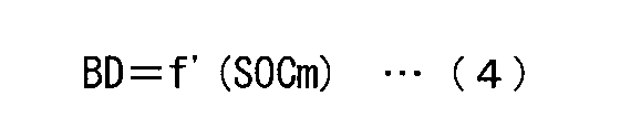
(主因子)
充電優先順位づけ指標ICm及び放電優先順位づけ指標IDmは、SOCの目標値SOCtのSOC演算部1204により演算されたSOCの演算値SOCmに対する差ΔSOCm=SOCt-SOCmを主因子として第1項に含む。充電優先順位づけ指標ICmの第1項の係数ACは正の値をとり、放電優先順位づけ指標IDmの第1項の係数ADは負の値をとる。これにより、差ΔSOCmが大きくなるほど充電優先順位が上がり放電優先順位が下がり、SOCの演算値SOCmが目標値SOCtを大きく下回るNaS電池1004に優先的に充電電力が割り当てられ、SOCの演算値SOCmが目標値SOCtを大きく上回るNaS電池1004に優先的に放電電力が割り当てられるので、SOCを目標値SOCtに近づけることが容易になる。 (Main factor)
The charge prioritization index ICm and the discharge prioritization index IDm include, as a main factor, a difference ΔSOCm = SOCt−SOCm, which is a difference between the SOC target value SOCt and the SOC calculated value SOCm calculated by theSOC calculation unit 1204. . The coefficient AC of the first term of the charge prioritization index ICm takes a positive value, and the coefficient AD of the first term of the discharge prioritization index IDm takes a negative value. Thus, as the difference ΔSOCm increases, the charging priority increases and the discharge priority decreases, and the charging power is preferentially assigned to the NaS battery 1004 where the calculated SOC value SOCm is significantly lower than the target value SOCt, and the calculated SOC value SOCm is Since discharge power is preferentially assigned to the NaS battery 1004 that greatly exceeds the target value SOCt, it becomes easy to bring the SOC close to the target value SOCt.
充電優先順位づけ指標ICm及び放電優先順位づけ指標IDmは、SOCの目標値SOCtのSOC演算部1204により演算されたSOCの演算値SOCmに対する差ΔSOCm=SOCt-SOCmを主因子として第1項に含む。充電優先順位づけ指標ICmの第1項の係数ACは正の値をとり、放電優先順位づけ指標IDmの第1項の係数ADは負の値をとる。これにより、差ΔSOCmが大きくなるほど充電優先順位が上がり放電優先順位が下がり、SOCの演算値SOCmが目標値SOCtを大きく下回るNaS電池1004に優先的に充電電力が割り当てられ、SOCの演算値SOCmが目標値SOCtを大きく上回るNaS電池1004に優先的に放電電力が割り当てられるので、SOCを目標値SOCtに近づけることが容易になる。 (Main factor)
The charge prioritization index ICm and the discharge prioritization index IDm include, as a main factor, a difference ΔSOCm = SOCt−SOCm, which is a difference between the SOC target value SOCt and the SOC calculated value SOCm calculated by the
(第1の副因子)
充電優先順位づけ指標ICm及び放電優先順位づけ指標IDmは、温度センサ1010により計測された温度の計測値Tmを第1の副因子として第2項に含む。充電優先順位づけ指標ICmの第2項の係数BCは、式(2)に示すようにSOCの演算値SOCmの関数f(SOCm)であることが望ましく、充電優先順位づけ指標ICmの第2項は、係数BCと温度の目標値Ttの計測値Tmに対する差ΔTm=Tt-Tmとの積である。 (First subfactor)
The charge prioritization index ICm and the discharge prioritization index IDm include the temperature measurement value Tm measured by thetemperature sensor 1010 as a first subfactor in the second term. The coefficient BC of the second term of the charge prioritization index ICm is preferably a function f (SOCm) of the calculated value SOCm of the SOC as shown in the equation (2), and the second term of the charge prioritization index ICm. Is the product of the coefficient BC and the difference ΔTm = Tt−Tm with respect to the measured value Tm of the target value Tt of temperature.
充電優先順位づけ指標ICm及び放電優先順位づけ指標IDmは、温度センサ1010により計測された温度の計測値Tmを第1の副因子として第2項に含む。充電優先順位づけ指標ICmの第2項の係数BCは、式(2)に示すようにSOCの演算値SOCmの関数f(SOCm)であることが望ましく、充電優先順位づけ指標ICmの第2項は、係数BCと温度の目標値Ttの計測値Tmに対する差ΔTm=Tt-Tmとの積である。 (First subfactor)
The charge prioritization index ICm and the discharge prioritization index IDm include the temperature measurement value Tm measured by the
関数f(SOCm)は、SOCの演算値SOCmが大きくなるほど大きくなることが望ましい。SOCmが相対的に小さいときには、差ΔTが大きくなっても温度の制限に起因して放電を停止せざるを得なくなる事態が発生しにくいので、係数BCを相対的に小さくすることが望ましいからである。また、SOCmが相対的に大きいときには、差ΔTが大きくなると温度の制限に起因して放電を停止せざるを得なくなる事態が発生しやすくなるので、係数BCを相対的に大きくすることが望ましいからである。
It is desirable that the function f (SOCm) increases as the calculated value SOCm of the SOC increases. When SOCm is relatively small, even if the difference ΔT is large, it is difficult to cause a situation where the discharge must be stopped due to the temperature limitation. Therefore, it is desirable to make the coefficient BC relatively small. is there. Further, when the SOCm is relatively large, a situation in which discharge must be stopped due to temperature limitation is likely to occur when the difference ΔT is large. Therefore, it is desirable to make the coefficient BC relatively large. It is.
電力貯蔵装置1002に要求される充放電電力の時間変化の実績又は予測に応じて第2項の係数を調整することも望ましい。
It is also desirable to adjust the coefficient of the second term in accordance with the track record or prediction of charge / discharge power required for the power storage device 1002.
その理由を説明する。第2項の係数BCを負の値とすると、温度の計測値Tmが高いNaS電池1004が優先的に充電される。NaS電池1004が充電されると、NaS電池1004の温度が下がるとともにΔSOCmが小さくなるので、NaS電池1004に放電させることが可能な放電時間及び放電電力の範囲が拡大する。したがって、第2項の係数BCを負の値とすることは、NaS電池1004に放電させることが可能な放電時間及び放電電力の範囲を拡大するという観点からは望ましいことである。
Explain why. When the coefficient BC of the second term is a negative value, the NaS battery 1004 having a high temperature measurement value Tm is preferentially charged. When the NaS battery 1004 is charged, the temperature of the NaS battery 1004 decreases and ΔSOCm decreases, so that the range of discharge time and discharge power that can be discharged to the NaS battery 1004 is expanded. Therefore, setting the coefficient BC of the second term to a negative value is desirable from the viewpoint of expanding the range of discharge time and discharge power that can be discharged to the NaS battery 1004.
その一方で、NaS電池1004が充電されると、放電優先順位が上がる傾向にあるため、充電されたNaS電池1004に放電電力が割り当てられる可能性が高くなる。これにより、第2項の係数BCを負の値とすると、温度の計測値Tmが高いNaS電池1004の充放電が繰り返され、温度の計測値Tmが高いNaS電池1004の温度がジュール熱によりさらに高くなってしまうという問題を生じる。
On the other hand, when the NaS battery 1004 is charged, the discharge priority tends to increase, so that there is a high possibility that discharge power is assigned to the charged NaS battery 1004. Accordingly, when the coefficient BC of the second term is a negative value, charging / discharging of the NaS battery 1004 having a high temperature measurement value Tm is repeated, and the temperature of the NaS battery 1004 having a high temperature measurement value Tm is further increased by Joule heat. This causes the problem of becoming high.
逆に、第2項の係数BCを正の値とすると、温度の計測値Tmが高いNaS電池1004が充電されにくくなる。NaS電池1004の充放電が行われていない間は、放熱によりNaS電池1004の温度は少しずつ低下する。充放電が行われていない間におけるNaS電池1004の温度の低下は、充電が行われている間におけるNaS電池1004の温度の低下よりも緩やかである。このため、短期的に見れば、NaS電池1004に放電させることが可能な放電時間及び放電電力の範囲は、充放電が行われていない間よりも充電が行われている間の方が拡大する。
Conversely, when the coefficient BC of the second term is a positive value, the NaS battery 1004 having a high temperature measurement value Tm is difficult to be charged. While the NaS battery 1004 is not being charged / discharged, the temperature of the NaS battery 1004 gradually decreases due to heat dissipation. The decrease in the temperature of the NaS battery 1004 while charging / discharging is not performed is more gradual than the decrease in the temperature of the NaS battery 1004 while charging is performed. For this reason, in the short term, the range of discharge time and discharge power that can be discharged by the NaS battery 1004 is larger during charging while it is not charged / discharged. .
しかし、充放電が行われていない間においては、ジュール熱は発生しないので、長期的に見れば、充放電を繰り返すよりも充放電を行わない方がNaS電池1004に放電させることが可能な放電時間及び放電電力の範囲が拡大する。
However, since no Joule heat is generated while charging / discharging is not performed, in the long term, it is possible to discharge the NaS battery 1004 without charging / discharging rather than repeating charging / discharging. The range of time and discharge power is expanded.
これらのことは、NaS電池1004に放電させることが可能な放電時間及び放電電力の範囲を拡大することができる第2項の係数BCは、電力貯蔵装置1002に要求される充放電電力の時間変化によって異なることを意味する。したがって、第2項の係数は、電力貯蔵装置1002に要求される充放電電力の時間変化の実績又は予測に応じて、NaS電池1004に放電させることが放電時間及び放電電力の範囲を拡大することができるように設定されることが望ましい。なお第2項の係数を「0」としても、電力貯蔵装置1002の運転は概ね適切な運転となる。
These factors are that the coefficient BC of the second term that can expand the range of discharge time and discharge power that can be discharged to the NaS battery 1004 is the time change of charge / discharge power required for the power storage device 1002. Means different. Therefore, the coefficient of the second term is that the discharge of the NaS battery 1004 to expand the range of discharge time and discharge power according to the track record or prediction of charge / discharge power required for the power storage device 1002. It is desirable to set so that Even when the coefficient of the second term is set to “0”, the operation of the power storage device 1002 is generally an appropriate operation.
ただし、NaS電池1004の仕様によっては、充放電が行われていない間におけるNaS電池1004の温度の低下が充電が行われている間におけるNaS電池1004の温度の低下がよりも急である場合もある。このような場合等は、第2項の係数BCは正の値であることが望ましい。これにより、温度の計測値Tmが高くなるほど充電優先順位が下がる。また、第2項の係数BCがSOCの演算値SOCmの関数であることも必須ではない。
However, depending on the specifications of the NaS battery 1004, the temperature of the NaS battery 1004 may decrease more rapidly than the temperature of the NaS battery 1004 while charging is being performed. is there. In such a case, the coefficient BC of the second term is preferably a positive value. As a result, the higher the measured temperature value Tm, the lower the charging priority. Further, it is not essential that the coefficient BC of the second term is a function of the calculated value SOCm of the SOC.
放電優先順位づけ指標IDmの第2項の係数BDは、式(4)に示すようにSOCの演算値SOCmの関数であることが望ましく、正の値をとり、放電優先順位づけ指標IDmの第2項は、係数BDと差ΔTm=Tt-Tmとの積である。これにより、温度の計測値Tmが高くなるほど放電優先順位が下がる。
The coefficient BD of the second term of the discharge prioritization index IDm is preferably a function of the calculated value SOCm of the SOC as shown in the equation (4), takes a positive value, and takes the first value of the discharge prioritization index IDm. The second term is the product of the coefficient BD and the difference ΔTm = Tt−Tm. As a result, the higher the temperature measurement value Tm, the lower the discharge priority.
関数f’(SOCm)は、SOCの演算値SOCmが大きくなるほど小さくなることが望ましい。SOCmが相対的に小さいときには、差ΔTが大きくなっても温度の制限に起因して放電を停止せざるを得なくなる事態が発生しにくいので、関数f’(SOCm)を相対的に大きくすることが望ましいからである。また、SOCmが相対的に大きいときには、差ΔTが大きくなると温度の制限に起因して放電を停止せざるを得なくなる事態が発生しやすくなるので、関数f’(SOCm)を相対的に小さくすることが望ましいからである。
It is desirable that the function f ′ (SOCm) decreases as the calculated value SOCm of the SOC increases. When the SOCm is relatively small, even if the difference ΔT is large, it is difficult to cause a situation in which the discharge must be stopped due to temperature limitation. Therefore, the function f ′ (SOCm) is relatively large. This is because it is desirable. Further, when SOCm is relatively large, a situation in which discharge must be stopped due to temperature limitation is likely to occur when the difference ΔT is large, and therefore the function f ′ (SOCm) is relatively small. This is because it is desirable.
温度の計測値Tmが高くなったNaS電池1004の温度がさらに高くなることを防止するため、温度の計測値Tmが閾値よりも高くなったNaS電池1004に放電優先順位をつけないようにしてもよい。ただし、放電優先順位をつけない場合でも充電優先順位をつけることは許容される。
In order to prevent the temperature of the NaS battery 1004 with the measured temperature value Tm from becoming higher, the discharge priority order may not be given to the NaS battery 1004 with the measured temperature value Tm higher than the threshold value. Good. However, even if the discharge priority is not set, it is allowed to set the charge priority.
NaS電池1004は、充電すると吸熱反応が発生し放電すると発熱反応が発生する二次電池であるので、これにより、温度が高いときに発熱反応の発生の頻度が少なくなるようにNaS電池1004が充放電され、NaS電池1004の温度が安定する。
Since the NaS battery 1004 is a secondary battery in which an endothermic reaction occurs when charged and an exothermic reaction occurs when discharged, the NaS battery 1004 is charged so that the frequency of the exothermic reaction is reduced when the temperature is high. As a result, the temperature of the NaS battery 1004 is stabilized.
充電すると発熱反応が発生し放電すると吸熱反応が発生する二次電池を採用する場合は、温度の計測値Tmが高くなるほど充電優先順位が下がるべきであるので、充電優先順位づけ指標ICmの第2項の係数BCは正の値をとる。第2項の係数BCは、式(2)に示すようにSOCの演算値SOCmの関数であることが望ましい。関数f(SOCm)は、SOCの演算値SOCmが大きくなるほど小さくなることが望ましい。SOCmが相対的に大きいときには、差ΔTmが大きくなっても温度の制限に起因して充電を停止せざるを得なくなる事態が発生しにくいので、関数f(SOCm)を相対的に大きくすることが望ましいからである。また、SOCmが相対的に小さいときには、差ΔTmが大きくなると温度の制限に起因して充電を停止せざるを得なくなる事態が発生しやすくなるので、関数f(SOCm)を相対的に小さくすることが望ましいからである。
When a secondary battery in which an exothermic reaction occurs when charging and an endothermic reaction occurs when discharged is used, the charging priority should be lowered as the temperature measurement value Tm increases, so the second charging priority index ICm is used. The term coefficient BC takes a positive value. The coefficient BC of the second term is preferably a function of the calculated value SOCm of SOC as shown in Expression (2). It is desirable that the function f (SOCm) decreases as the calculated value SOCm of the SOC increases. When SOCm is relatively large, even if the difference ΔTm increases, it is difficult to cause a situation where charging must be stopped due to temperature limitations. Therefore, the function f (SOCm) may be relatively increased. This is desirable. Further, when the SOCm is relatively small, if the difference ΔTm is large, a situation in which charging must be stopped due to temperature limitation is likely to occur. Therefore, the function f (SOCm) should be relatively small. This is because it is desirable.
式(3)に示す放電優先順位づけ指標IDmに代えて、式(5)に示す放電優先順位づけ指標IDmが使用されてもよい。式(5)に示す放電優先順位づけ指標IDmにおいては、式(3)の第2項BD×ΔTmがSOCの演算値SOCm及び温度の計測値Tmの関数f’’(SOCm,Tm)に置き換えられている。
Instead of the discharge prioritization index IDm shown in Formula (3), the discharge prioritization index IDm shown in Formula (5) may be used. In the discharge prioritization index IDm shown in Expression (5), the second term BD × ΔTm in Expression (3) is replaced with a function f ″ (SOCm, Tm) of the calculated value SOCm of SOC and the measured value Tm of temperature. It has been.

式(5)に示す放電優先順位づけ指標IDmが使用される場合は、複数のNaS電池1004の各々に放電電力の第1の上限値U1m及び第2の上限値U2mが設定される。第1の上限値U1mは、NaS電池1004の仕様又はNaS電池1004からの放電経路の仕様によって決まる放電電力の最大値であり、電力割り当て部1214は第1の上限値U1m以下の放電電力を複数のNaS電池1004の各々に割り当てる。第2の上限値U2は、NaS電池1004の温度が上限温度以下に維持される放電電力の最大値である。第2の上限値U2mは第1の上限値U1m以下に設定される。第1の上限値U1mは、複数のNaS電池1004の全部について同じであってもよいし、複数のNaS電池1004の全部又は一部について異なってもよい。第2の上限値U2mも、複数のNaS電池1004の全部について同じであってもよいし、複数のNaS電池1004の全部又は一部について異なってもよい。
When the discharge prioritization index IDm shown in Equation (5) is used, the first upper limit value U1m and the second upper limit value U2m of the discharge power are set in each of the plurality of NaS batteries 1004. The first upper limit value U1m is the maximum value of the discharge power determined by the specification of the NaS battery 1004 or the specification of the discharge path from the NaS battery 1004, and the power allocation unit 1214 generates a plurality of discharge powers equal to or less than the first upper limit value U1m. Assigned to each NaS battery 1004. The second upper limit value U2 is the maximum value of discharge power at which the temperature of the NaS battery 1004 is maintained below the upper limit temperature. The second upper limit value U2m is set to be equal to or less than the first upper limit value U1m. The first upper limit value U1m may be the same for all of the plurality of NaS batteries 1004, or may be different for all or part of the plurality of NaS batteries 1004. The second upper limit value U2m may be the same for all of the plurality of NaS batteries 1004, or may be different for all or some of the plurality of NaS batteries 1004.
関数f’’(SOCm,Tm)は、第2の上限値U2mの第1の上限値U1mに対する比U2m/U1mを因子として含み、比U2m/U1mが大きくなるほど大きくなる。したがって、比U2m/U1mが大きくなるほど放電優先順位が上がる。
The function f ″ (SOCm, Tm) includes a ratio U2m / U1m of the second upper limit value U2m to the first upper limit value U1m as a factor, and increases as the ratio U2m / U1m increases. Accordingly, the discharge priority increases as the ratio U2m / U1m increases.
第2の上限値U2mは、DOD(放電深度)が100%に達するまで連続放電が可能な放電電力の最大値である。
The second upper limit value U2m is the maximum value of discharge power that allows continuous discharge until the DOD (discharge depth) reaches 100%.
図4は、順位づけ部1212によって参照される放電時のNaS電池1004のDODと温度との関係を記述した情報の例を示す図である。図4には、横軸をDOD、縦軸を温度にとって、DODが0%であり温度が300℃である初期状態から1.0MW,0.8MW,0.6MWの放電電力を放電した場合のDOD及び温度の変化がそれぞれDOD-温度特性線1912,1914,1916に示され、DODが30%であり温度が305℃である初期状態から0.8MWの放電電力を放電した場合のDOD及び温度の変化がDOD-温度特性線1918に示されている。
FIG. 4 is a diagram illustrating an example of information describing the relationship between the DOD and temperature of the NaS battery 1004 at the time of discharging referred to by the ranking unit 1212. In FIG. 4, when the horizontal axis is DOD and the vertical axis is temperature, the discharge power of 1.0 MW, 0.8 MW, and 0.6 MW is discharged from the initial state where the DOD is 0% and the temperature is 300 ° C. Changes in DOD and temperature are shown in DOD-temperature characteristic lines 1912, 1914 and 1916, respectively. DOD and temperature when 0.8 MW of discharge power is discharged from the initial state where DOD is 30% and temperature is 305 ° C. This change is shown in the DOD-temperature characteristic line 1918.
順位づけ部1212が図4に示すNaS電池1004のDODと温度との関係を記述した参照情報を参照することにより、例えば、温度の計測値Tmが300℃でありDODの演算値DODmが0%であれば、放出電力を0.6MW以下とすれば温度が上限温度の340℃以下に維持されDODが100%に達するまで連続放電が可能であること、すなわち、第2の上限値U2mを0.6MWとすべきことがDOD-温度特性線1916からわかる。また、温度の計測値Tmが305℃でありDODの演算値DODが30%であれば、放出電力を0.8MW以下とすれば温度が上限温度の340℃以下に維持されDODが100%に達するまで連続放電が可能であること、すなわち、第2の上限値U2mを0.8MWとすべきことがDOD-温度特性線1918からわかる。
The ranking unit 1212 refers to the reference information describing the relationship between the DOD of the NaS battery 1004 and the temperature shown in FIG. 4, for example, the measured value Tm of the temperature is 300 ° C., and the calculated value DODm of the DOD is 0%. If the discharge power is 0.6 MW or less, the temperature is maintained at the upper limit temperature of 340 ° C. or lower and continuous discharge is possible until the DOD reaches 100%, that is, the second upper limit value U2m is set to 0. It can be seen from the DOD-temperature characteristic line 1916 that it should be 6 MW. Also, if the measured value Tm of the temperature is 305 ° C. and the calculated value DOD of the DOD is 30%, the temperature is maintained at the upper limit temperature of 340 ° C. or less and the DOD is reduced to 100% if the emission power is 0.8 MW or less It can be seen from the DOD-temperature characteristic line 1918 that continuous discharge is possible until it reaches, that is, the second upper limit value U2m should be 0.8 MW.
一般的には、温度が計測値TmでありDODが演算値DODmである初期状態から温度が上限温度以下でありDODが100%である末期状態へ至るDOD-温度特性線を特定し、特定したDOD-温度特性線に沿ってNaS電池1004の温度及びDODを変化させる放電電力を特定することにより、温度が上限温度以下に維持されDODが100%に達するまで連続放電が可能な放出電力の第2の上限値U2mが特定される。
In general, the DOD-temperature characteristic line from the initial state where the temperature is the measured value Tm and the DOD is the calculated value DODm to the final state where the temperature is below the upper limit temperature and the DOD is 100% is specified and specified. By specifying the discharge power that changes the temperature and DOD of the NaS battery 1004 along the DOD-temperature characteristic line, the discharge power can be continuously discharged until the temperature is kept below the upper limit temperature and the DOD reaches 100%. An upper limit value U2m of 2 is specified.
放電電力を第1の上限値U1mに一致させたときのNaS電池1004の温度及びDODの変化を表し温度が上限温度でありDODが100%である末期状態へ至るDOD-温度特性線1920よりも温度が低い範囲1922に初期状態が含まれるNaS電池1004は、DODが100%に達するまで第1の上限値U1mに一致する放出電力を連続放電しても温度は上限温度に達しないので、第2の上限値U2mは第1の上限値U1mに一致させられる。
It represents the change in the temperature and DOD of the NaS battery 1004 when the discharge power is made to coincide with the first upper limit value U1m, and represents the end state where the temperature is the upper limit temperature and the DOD is 100%. Since the NaS battery 1004 whose initial state is included in the low temperature range 1922 does not reach the upper limit temperature even if the discharged power corresponding to the first upper limit value U1m is continuously discharged until the DOD reaches 100%, the temperature does not reach the upper limit temperature. The upper limit value U2m of 2 is made to coincide with the first upper limit value U1m.
NaS電池1004の温度は、下限温度と上限温度との間に維持され、NaS電池1004のDODは、0%と100%との間にある。
The temperature of the NaS battery 1004 is maintained between the lower limit temperature and the upper limit temperature, and the DOD of the NaS battery 1004 is between 0% and 100%.
NaS電池1004の熱容量及び熱抵抗の影響により、NaS電池1004からの電力の放電を停止してもNaS電池1004の温度の上昇はすぐにはとまらないので、「上限温度」は、NaS電池1004が正常に動作する最高温度よりも低く設定することが望ましい。
Since the rise of the temperature of the NaS battery 1004 does not stop immediately even if the discharge of power from the NaS battery 1004 is stopped due to the influence of the heat capacity and thermal resistance of the NaS battery 1004, the “upper limit temperature” is determined by the NaS battery 1004. It is desirable to set it lower than the maximum temperature at which it operates normally.
図5に示すように、NaS電池1004の状態の変化を大まかにたどった直線状のDOD-温度特性線1924であっても高い精度を有する第2の上限値U2mが演算されるが、NaS電池1004の状態の変化を厳密にたどった曲線状のDOD-温度特性線1926であればより高い精度を有する第2の上限値U2mが演算される。図5に示すDOD-温度特性線1926は、初期状態の直後においてDODに対する温度の変化率が低くなる弓形状を有する。初期状態の直後においてDODに対する温度の変化率が低くなるのは、NaS電池1004の熱容量及び熱抵抗の影響である。
As shown in FIG. 5, the second upper limit value U2m having high accuracy is calculated even with a linear DOD-temperature characteristic line 1924 that roughly follows the change in the state of the NaS battery 1004. In the case of a curved DOD-temperature characteristic line 1926 that closely follows the change in the state of 1004, the second upper limit value U2m having higher accuracy is calculated. A DOD-temperature characteristic line 1926 shown in FIG. 5 has a bow shape in which the rate of change of temperature with respect to DOD is low immediately after the initial state. The rate of change in temperature relative to DOD immediately after the initial state is affected by the heat capacity and thermal resistance of the NaS battery 1004.
DODが100%に達するまで連続放電が可能な放電電力の最大値に代えて、設定された時間が経過するまで連続放電が可能な放出電力の最大値を第2の上限値U2mとしてもよい。
Instead of the maximum value of the discharge power that can be continuously discharged until the DOD reaches 100%, the maximum value of the discharge power that can be continuously discharged until the set time elapses may be set as the second upper limit value U2m.
(第2の副因子)
充電優先順位づけ指標ICm及び放電優先順位づけ指標IDmは、積算充放電電力演算部1206により演算された積算充放電電力の演算値IPmを第2の副因子として第3項に含む。充電優先順位づけ指標ICmの第3項の係数CC及び放電優先順位づけ指標IDmの第3項の係数CDは負の値をとる。これにより、積算充放電電力の演算値IPmが小さくなるほど充電優先順位及び放電優先順位が上がる。これにより、積算充放電電力が少ないNaS電池1004に優先的に充電電力及び放電電力が割り当てられるので、NaS電池1004の積算充放電電力が均一になり、NaS電池1004の劣化が均一になる。 (Second subfactor)
The charge prioritization index ICm and the discharge prioritization index IDm include the calculated value IPm of the integrated charge / discharge power calculated by the integrated charge / dischargepower calculation unit 1206 in the third term as a second subfactor. The coefficient CC of the third term of the charge prioritization index ICm and the coefficient CD of the third term of the discharge prioritization index IDm take negative values. Thereby, the charge priority and the discharge priority increase as the calculated value IPm of the integrated charge / discharge power decreases. As a result, charging power and discharging power are preferentially assigned to the NaS battery 1004 having a small accumulated charging / discharging power, so that the accumulating charging / discharging power of the NaS battery 1004 becomes uniform, and the deterioration of the NaS battery 1004 becomes uniform.
充電優先順位づけ指標ICm及び放電優先順位づけ指標IDmは、積算充放電電力演算部1206により演算された積算充放電電力の演算値IPmを第2の副因子として第3項に含む。充電優先順位づけ指標ICmの第3項の係数CC及び放電優先順位づけ指標IDmの第3項の係数CDは負の値をとる。これにより、積算充放電電力の演算値IPmが小さくなるほど充電優先順位及び放電優先順位が上がる。これにより、積算充放電電力が少ないNaS電池1004に優先的に充電電力及び放電電力が割り当てられるので、NaS電池1004の積算充放電電力が均一になり、NaS電池1004の劣化が均一になる。 (Second subfactor)
The charge prioritization index ICm and the discharge prioritization index IDm include the calculated value IPm of the integrated charge / discharge power calculated by the integrated charge / discharge
積算充放電電力演算部1206に代えて積算充放電電流演算部が設けられた場合は、積算充放電電力の演算値IPmに代えて積算充放電電流の演算値が充電優先順位づけ指標ICm及び放電優先順位づけ指標IDmに第2の副因子として含まれ、積算充放電電流が少ないNaS電池1004に優先的に充電電力及び放電電力が割り当てられる。より一般的には、使用履歴反映量演算部により演算された使用履歴を反映する量が充電優先順位づけ指標ICm及び放電優先順位づけ指標IDmに第2の副因子として含まれ、使用履歴が少ないNaS電池1004に優先的に充電電力及び放電電力が割り当てられる。
When an integrated charge / discharge current calculation unit is provided in place of the integrated charge / discharge power calculation unit 1206, the calculated value of the integrated charge / discharge current is replaced with the charge prioritization index ICm and the discharge instead of the calculated value IPm of the integrated charge / discharge power. Charging power and discharging power are preferentially assigned to the NaS battery 1004 that is included as a second sub-factor in the priority index IDm and has a low integrated charge / discharge current. More generally, the amount reflecting the usage history calculated by the usage history reflection amount calculation unit is included as the second sub-factor in the charge prioritization index ICm and the discharge prioritization index IDm, and the usage history is small. Charge power and discharge power are preferentially assigned to the NaS battery 1004.
(第3及び第4の副因子)
放電容量の演算値の補正が充電末において行われる場合、充電優先順位づけ指標ICm及び放電優先順位づけ指標IDmは、要否判定部1208の判定結果を第3の因子として第4項に含み、充電末/放電末検出部1210の検出結果を第4の因子として第4項に含む。充電優先順位づけ指標ICmの第4項の係数DCは負の値をとり、放電優先順位づけ指標IDmの第4項の係数DDは正の値をとり、放電容量の演算値の補正の状態をあらわす値Smは、要否判定部1208により充電末における放電容量の演算値の補正が必要であると判定されると0から-1へ変化し、充電末/放電末検出部1210により充電末への到達が検出されると-1から1へ変化し、SOCが目標値SOCtに近づくと1から0へ変化する。これにより、要否判定部1208により充電末における放電容量の演算値の補正が必要であると判定されると充電優先順位が上がり放電優先順位が下がる。また、充電末/放電末検出部1210により充電末への到達が検出されると充電優先順位が下がり放電優先順位が上がる。これにより、充電末における放電容量の演算値の補正が必要なNaS電池1004に優先的に充電電力が割り当てられ、充電末における放電容量の演算値の補正が不要なNaS電池1004に優先的に放電電力が割り当てられるので、充電末における放電容量の演算値の補正が迅速に行われる。また、充電末へ到達していないNaS電池1004に優先的に充電電力が割り当てられ、充電末へ到達したNaS電池1004に優先的に放電電力が割り当てられるので、充電末における放電容量の演算値の補正の後にSOCを目標値に近づけることが容易になる。 (Third and fourth subfactors)
When the correction of the calculated value of the discharge capacity is performed at the end of charging, the charge prioritization index ICm and the discharge prioritization index IDm include the determination result of thenecessity determination unit 1208 as the third factor in the fourth term, The detection result of the end-of-charge / end-of-discharge detection unit 1210 is included in the fourth term as a fourth factor. The coefficient DC of the fourth term of the charge prioritization index ICm takes a negative value, the coefficient DD of the fourth term of the discharge prioritization index IDm takes a positive value, and indicates the state of correction of the calculated value of the discharge capacity. The expressed value Sm changes from 0 to −1 when the necessity determining unit 1208 determines that the calculation value of the discharge capacity at the end of charging is necessary, and the charging end / discharge end detecting unit 1210 returns to the end of charging. -1 is changed to 1 when the arrival is detected, and is changed from 1 to 0 when the SOC approaches the target value SOCt. As a result, if the necessity determination unit 1208 determines that the calculation value of the discharge capacity at the end of charging is required to be corrected, the charging priority is increased and the discharging priority is decreased. When the end of charge / discharge end detection unit 1210 detects the end of charge, the charge priority is lowered and the discharge priority is raised. Thereby, charging power is preferentially assigned to the NaS battery 1004 that requires correction of the calculated value of the discharge capacity at the end of charging, and preferentially discharged to the NaS battery 1004 that does not require correction of the calculated value of the discharge capacity at the end of charging. Since electric power is allocated, the calculation value of the discharge capacity at the end of charging is quickly corrected. Further, since the charging power is preferentially assigned to the NaS battery 1004 that has not reached the end of charging, and the discharging power is preferentially assigned to the NaS battery 1004 that has reached the end of charging, the calculated value of the discharge capacity at the end of charging is calculated. It becomes easy to bring the SOC close to the target value after the correction.
放電容量の演算値の補正が充電末において行われる場合、充電優先順位づけ指標ICm及び放電優先順位づけ指標IDmは、要否判定部1208の判定結果を第3の因子として第4項に含み、充電末/放電末検出部1210の検出結果を第4の因子として第4項に含む。充電優先順位づけ指標ICmの第4項の係数DCは負の値をとり、放電優先順位づけ指標IDmの第4項の係数DDは正の値をとり、放電容量の演算値の補正の状態をあらわす値Smは、要否判定部1208により充電末における放電容量の演算値の補正が必要であると判定されると0から-1へ変化し、充電末/放電末検出部1210により充電末への到達が検出されると-1から1へ変化し、SOCが目標値SOCtに近づくと1から0へ変化する。これにより、要否判定部1208により充電末における放電容量の演算値の補正が必要であると判定されると充電優先順位が上がり放電優先順位が下がる。また、充電末/放電末検出部1210により充電末への到達が検出されると充電優先順位が下がり放電優先順位が上がる。これにより、充電末における放電容量の演算値の補正が必要なNaS電池1004に優先的に充電電力が割り当てられ、充電末における放電容量の演算値の補正が不要なNaS電池1004に優先的に放電電力が割り当てられるので、充電末における放電容量の演算値の補正が迅速に行われる。また、充電末へ到達していないNaS電池1004に優先的に充電電力が割り当てられ、充電末へ到達したNaS電池1004に優先的に放電電力が割り当てられるので、充電末における放電容量の演算値の補正の後にSOCを目標値に近づけることが容易になる。 (Third and fourth subfactors)
When the correction of the calculated value of the discharge capacity is performed at the end of charging, the charge prioritization index ICm and the discharge prioritization index IDm include the determination result of the
放電容量の演算値の補正が放電末において行われる場合、要否判定部1208により放電末における放電容量の演算値の補正が必要であると判定されると充電優先順位が下がり放電優先順位が上がるべきである。また、充電末/放電末検出部1210により放電末への到達が検出されると充電優先順位が上がり放電優先順位が下がるべきである。このため、充電優先順位づけ指標ICmの第4項の係数DCは正の値をとり、放電優先順位づけ指標IDmの第4項の係数DDは負の値をとり、放電容量の演算値の補正の状態をあらわす値Smは、要否判定部1208により放電末における放電容量の演算値の補正が必要であると判定されると0から-1へ変化し、充電末/放電末検出部1210により放電末への到達が検出されると-1から1へ変化し、SOCが目標値SOCtに近づくと1から0へ変化する。これにより、放電末における放電容量の演算値の補正が不要なNaS電池1004に優先的に充電電力が割り当てられ、放電末における放電容量の演算値の補正が必要なNaS電池1004に優先的に放電電力が割り当てられるので、放電末における放電容量の演算値の補正が迅速に行われる。また、放電末へ到達したNaS電池1004に優先的に充電電力が割り当てられ、放電末へ到達していないNaS電池1004に優先的に放電電力が割り当てられるので、放電容量の演算値の補正の後においてSOCを目標値に近づけることが容易になる。
When correction of the calculated value of discharge capacity is performed at the end of discharge, if the necessity determination unit 1208 determines that correction of the calculated value of discharge capacity at the end of discharge is necessary, the charge priority is lowered and the discharge priority is raised. Should. In addition, when the end of charge / end of discharge detection unit 1210 detects arrival of the end of discharge, the charge priority should be raised and the discharge priority should be lowered. For this reason, the coefficient DC of the fourth term of the charge prioritization index ICm takes a positive value, the coefficient DD of the fourth term of the discharge prioritization index IDm takes a negative value, and the calculation value of the discharge capacity is corrected. The value Sm representing the state of changes from 0 to −1 when the necessity determining unit 1208 determines that the calculation value of the discharge capacity at the end of the discharge needs to be corrected. When arrival at the end of the discharge is detected, the value changes from -1 to 1, and when the SOC approaches the target value SOCt, the value changes from 1 to 0. As a result, charging power is preferentially assigned to the NaS battery 1004 that does not require correction of the calculated value of the discharge capacity at the end of discharge, and preferentially discharged to the NaS battery 1004 that requires correction of the calculated value of the discharge capacity at the end of discharge. Since electric power is allocated, the calculation value of the discharge capacity at the end of the discharge is quickly corrected. In addition, since the charging power is preferentially assigned to the NaS battery 1004 that has reached the end of discharge, and the discharging power is preferentially assigned to the NaS battery 1004 that has not reached the end of discharge, after correcting the calculated value of the discharge capacity In this case, it is easy to bring the SOC close to the target value.
(因子の寄与の大きさ)
係数AC,BC,CC,DCの絶対値は、それぞれ、主因子、第1の副因子、第2の副因子、第3及び第4の副因子の充電優先順位への寄与の大きさを示す。また、係数AD,BD,CD,DDの絶対値は、それぞれ、主因子、第1の副因子、第2の副因子、第3及び第4の副因子の充電優先順位への寄与の大きさを示す。充電優先順位づけ指標ICmが小さくなるほど充電優先順位を上げる場合は、係数AC,BC,CC,DCの正負は反転され、放電優先順位づけ指標IDmが小さくなるほど放電優先順位を上げる場合は、係数AD,BD,CD,DDの正負は反転される。 (The magnitude of the factor contribution)
The absolute values of the coefficients AC, BC, CC, and DC indicate the magnitude of the contribution of the main factor, the first subfactor, the second subfactor, the third and fourth subfactors to the charging priority, respectively. . The absolute values of the coefficients AD, BD, CD, and DD are the magnitudes of contribution of the main factor, the first sub-factor, the second sub-factor, the third and fourth sub-factors to the charging priority, respectively. Indicates. When the charging priority is increased as the charging priority index ICm decreases, the signs of the coefficients AC, BC, CC, and DC are reversed, and when the discharging priority is increased as the discharge priority index IDm decreases, the coefficient AD , BD, CD, DD are inverted.
(因子の削除及び追加)
式(1)に示す充電優先順位づけ指標ICm及び式(3)に示す放電優先順位づけ指標IDmは、例示であり、電力貯蔵装置1002の仕様に応じて変更される。特に、第1から第3までの副因子の全部又は一部を削除すること及び第1から第3までの副因子以外の副因子を追加することは当然に予定されている。 (Deleting and adding factors)
The charge prioritization index ICm shown in Expression (1) and the discharge prioritization index IDm shown in Expression (3) are examples, and are changed according to the specifications of thepower storage device 1002. In particular, it is naturally planned to delete all or part of the first to third subfactors and to add subfactors other than the first to third subfactors.
式(1)に示す充電優先順位づけ指標ICm及び式(3)に示す放電優先順位づけ指標IDmは、例示であり、電力貯蔵装置1002の仕様に応じて変更される。特に、第1から第3までの副因子の全部又は一部を削除すること及び第1から第3までの副因子以外の副因子を追加することは当然に予定されている。 (Deleting and adding factors)
The charge prioritization index ICm shown in Expression (1) and the discharge prioritization index IDm shown in Expression (3) are examples, and are changed according to the specifications of the
(充電優先順位づけ指標ICm及び放電優先順位づけ指標IDmの共通化)
式(1)に示す充電優先順位づけ指標ICm及び式(3)に示す放電優先順位づけ指標IDmに含まれる因子には、充電優先順位及び放電優先順位の一方を上げ他方を下げることに寄与する因子と、充電優先順位及び放電優先順位の両方を上げる又は下げることに寄与する因子と、が混在している。このため、充電優先順位づけ指標ICmと放電優先順位づけ指標IDmとが別々に決められる。 (Commonization of charge prioritization index ICm and discharge prioritization index IDm)
Factors included in the charge prioritization index ICm shown in equation (1) and the discharge prioritization index IDm shown in equation (3) contribute to raising one of the charge priority and discharge priority and lowering the other. Factors and factors that contribute to raising or lowering both charging priority and discharging priority are mixed. For this reason, the charge prioritization index ICm and the discharge prioritization index IDm are determined separately.
しかし、このような混在が解消されれば、充電優先順位づけ指標ICmと放電優先順位づけ指標IDmとを共通化してもよい。ただし、共通化した場合、共通化された指標が大きくなるほど充電優先順位を上げ放電優先順位を下げること、又は、共通化された指標が小さくなるほど充電優先順位を上げ放電優先順位を下げることが要求される。
However, if such a mixture is eliminated, the charge prioritization index ICm and the discharge prioritization index IDm may be shared. However, in the case of commonization, the higher the common index, the higher the charging priority and the lower the discharge priority, or the smaller the common index, the higher the charging priority and the lower the discharge priority. Is done.
(電力割り当て部1214)
電力割り当て部1214は、順位づけ部1212によりつけられた充電優先順位が高いNaS電池1004から低いNaS電池1004へ順に充電電力を割り当て、順位づけ部1212によりつけられた放電優先順位が高いNaS電池1004から低いNaS電池1004へ順に放電電力を割り当てる。複数のNaS電池1004の各々への充電電力の割り当てにあたっては、未割り当ての充電電力がNaS電池1004の最大充電電力より多い場合は、最大充電電力が割り当てられ、未割り当ての充電電力がNaS電池1004の最大充電電力と同じかNaS電池1004の最大充電電力より少ない場合は未割り当ての充電電力の全部が割り当てられる。同様に、複数のNaS電池1004の各々への放電電力の割り当てにあたっては、未割り当ての放電電力がNaS電池1004の最大放電電力より多い場合は、最大放電電力が割り当てられ、未割り当ての放電電力がNaS電池1004の最大放電電力と同じかNaS電池1004の最大放電電力より少ない場合は未割り当ての放電電力の全部が割り当てられる。 (Power allocation unit 1214)
Thepower allocating unit 1214 sequentially allocates charging power from the NaS battery 1004 with a high charging priority assigned by the ranking unit 1212 to the NaS battery 1004 with a low charging priority, and the NaS battery 1004 with a high discharging priority assigned by the ranking unit 1212. To the lower NaS battery 1004 in order. In assigning the charging power to each of the plurality of NaS batteries 1004, if the unassigned charging power is greater than the maximum charging power of the NaS battery 1004, the maximum charging power is assigned, and the unassigned charging power is assigned to the NaS battery 1004. If the charging power is equal to or less than the maximum charging power of the NaS battery 1004, all of the unassigned charging power is allocated. Similarly, when assigning the discharge power to each of the plurality of NaS batteries 1004, if the unassigned discharge power is larger than the maximum discharge power of the NaS battery 1004, the maximum discharge power is assigned, and the unassigned discharge power is If the maximum discharge power of the NaS battery 1004 is equal to or less than the maximum discharge power of the NaS battery 1004, all of the unassigned discharge power is allocated.
電力割り当て部1214は、順位づけ部1212によりつけられた充電優先順位が高いNaS電池1004から低いNaS電池1004へ順に充電電力を割り当て、順位づけ部1212によりつけられた放電優先順位が高いNaS電池1004から低いNaS電池1004へ順に放電電力を割り当てる。複数のNaS電池1004の各々への充電電力の割り当てにあたっては、未割り当ての充電電力がNaS電池1004の最大充電電力より多い場合は、最大充電電力が割り当てられ、未割り当ての充電電力がNaS電池1004の最大充電電力と同じかNaS電池1004の最大充電電力より少ない場合は未割り当ての充電電力の全部が割り当てられる。同様に、複数のNaS電池1004の各々への放電電力の割り当てにあたっては、未割り当ての放電電力がNaS電池1004の最大放電電力より多い場合は、最大放電電力が割り当てられ、未割り当ての放電電力がNaS電池1004の最大放電電力と同じかNaS電池1004の最大放電電力より少ない場合は未割り当ての放電電力の全部が割り当てられる。 (Power allocation unit 1214)
The
例えば、割り当てなければならない全充電電力が1.5MWであり複数のNaS電池1004の各々の最大充電電力が1MWである場合、充電優先順位が1番目のNaS電池1004に最大充電電力と同じ1MWの充電電力が割り当てられ、充電優先順位が2番目のNaS電池1004に残余の0.5MWの充電電力が割り当てられ、充電優先順位が3番目及び4番目のNaS電池1004には充電電力が割り当てられない。
For example, if the total charging power that must be allocated is 1.5 MW and the maximum charging power of each of the plurality of NaS batteries 1004 is 1 MW, the charging priority is 1 MW that is the same as the maximum charging power for the first NaS battery 1004. Charging power is allocated, the remaining charging power of 0.5 MW is allocated to the NaS battery 1004 with the second charging priority, and charging power is not allocated to the third and fourth NaS batteries 1004 with the charging priority. .
(充電優先順位及び放電優先順位の充電電力及び放電電力の割り当てへの反映)
図6は、充電優先順位及び放電優先順位の充電電力及び放電電力の割り当てへの反映を説明するグラフである。図7は、充電優先順位の充電電力の割り当てへの反映を説明するグラフである。図6及び図7のグラフでは、時間が横軸、全充放電電力が縦軸にとられている。正の全充放電電力は全充電電力をあらわし、負の充放電電力は全放電電力をあらわす。図6及び図7のグラフには、NaS電池A,B,C,Dに割り当てられた充電電力及び放電電力がそれぞれに固有のハッチングであらわされている。 (Reflecting the charging priority and discharging priority in the allocation of charging power and discharging power)
FIG. 6 is a graph for explaining the reflection of charging priority and discharging priority on allocation of charging power and discharging power. FIG. 7 is a graph for explaining the reflection of the charging priority order to the allocation of charging power. In the graphs of FIGS. 6 and 7, time is plotted on the horizontal axis and total charge / discharge power is plotted on the vertical axis. Positive total charge / discharge power represents total charge power, and negative charge / discharge power represents total discharge power. In the graphs of FIGS. 6 and 7, the charging power and the discharging power allocated to the NaS batteries A, B, C, and D are represented by their own hatching.
NaS電池A,B,C,Dの順に充電優先順位が低くなる場合、図6に示すように、全充電電力が増加すると、NaS電池A,B,C,Dの順に充電電力が割り当てられ、全充電電力が減少すると、NaS電池D,C,B,Aの順に充電電力の割り当てが解消される。
When the charging priority is lowered in the order of NaS batteries A, B, C, and D, as shown in FIG. 6, when the total charging power is increased, charging power is assigned in the order of NaS batteries A, B, C, and D. When the total charging power decreases, the allocation of charging power is canceled in the order of NaS batteries D, C, B, and A.
同様に、NaS電池D,C,B,Aの順に放電優先順位が低くなる場合、図6に示すように、全放電電力が増加すると、NaS電池D,C,B,Aの順に放電電力が割り当てられ、全放電電力が減少すると、NaS電池A,B,C,Dの順に放電電力の割り当てが解消される。
Similarly, when the discharge priority is lowered in the order of NaS batteries D, C, B, A, as shown in FIG. 6, when the total discharge power is increased, the discharge power is increased in the order of NaS batteries D, C, B, A. When assigned and the total discharge power is reduced, the assignment of discharge power is canceled in the order of NaS batteries A, B, C, and D.
タイミングTにおいてNaS電池A,B,C,Dの順に充電優先順位が低くなる状態からNaS電池B,A,C,Dの順に充電優先順位が低くなる状態に変化した場合、図7に示すように、充電優先順位の変化が充電電力の割り当てに即時に反映される。このことは、放電電力の割り当てにおいても同様である。ただし、「即時」とはいっても、計測、演算等の処理に要する時間だけ反映が遅れることは許容される。
When the state in which the charging priority is lowered in the order of NaS batteries A, B, C, and D at timing T changes to the state in which the charging priority is lowered in the order of NaS batteries B, A, C, and D, as shown in FIG. In addition, the change in charge priority is immediately reflected in the allocation of charge power. The same applies to the allocation of discharge power. However, even if it is “immediately”, the reflection is allowed to be delayed by the time required for processing such as measurement and calculation.
(充放電司令部1216)
充放電司令部1216は、電力割り当て部1214により割り当てられた充放電電力の充放電を双方向変換器1012に指令する。 (Charge / Discharge Command Unit 1216)
The charge /discharge command unit 1216 instructs the bidirectional converter 1012 to charge / discharge the charge / discharge power allocated by the power allocation unit 1214.
充放電司令部1216は、電力割り当て部1214により割り当てられた充放電電力の充放電を双方向変換器1012に指令する。 (Charge / Discharge Command Unit 1216)
The charge /
また、充放電司令部1216は、要否判定部1208により放電容量の演算値の補正が必要であると判定されたNaS電池1004を放電容量の演算値の補正が行われる充電末又は放電末まで充放電させる指令を双方向変換器1012へ出力する。
In addition, the charge / discharge command unit 1216 determines that the necessity determination unit 1208 determines that the calculation value of the discharge capacity needs to be corrected until the charge end or the end of discharge at which the calculation value of the discharge capacity is corrected. A command for charging / discharging is output to bidirectional converter 1012.
さらに、充放電司令部1216は、双方向変換器1012の運転の停止及び再開を制御する。
Furthermore, the charge / discharge command unit 1216 controls the stop and restart of the operation of the bidirectional converter 1012.
(放電容量の演算値の補正)
図8は、NaS電池1004の放電深度と電圧との関係を示すグラフである。 (Correction of calculated value of discharge capacity)
FIG. 8 is a graph showing the relationship between the discharge depth ofNaS battery 1004 and the voltage.
図8は、NaS電池1004の放電深度と電圧との関係を示すグラフである。 (Correction of calculated value of discharge capacity)
FIG. 8 is a graph showing the relationship between the discharge depth of
図8に示すように、ナトリウム硫化物(Na2S5)及び単体イオウ(S)が正極活物質として存在する二相域にある充電末(図8のグラフの左端付近)においては、充電がすすむほどNaS電池1004の電圧が高くなる。充電末以外の二相域においては、電圧は放電深度によらず概ね一定である。ナトリウム硫化物(Na2Sx)のみが正極活物質として存在する一相域にある放電末(図8のグラフの右端付近)においては、放電が進むほどNaS電池1004の電圧が低くなる。
As shown in FIG. 8, at the end of charging (near the left end of the graph of FIG. 8) in the two-phase region where sodium sulfide (Na 2 S 5 ) and simple sulfur (S) exist as the positive electrode active material, charging is not performed. The voltage of the NaS battery 1004 increases as the progress proceeds. In the two-phase region other than the end of charging, the voltage is substantially constant regardless of the depth of discharge. At the end of discharge (near the right end of the graph of FIG. 8) in a one-phase region where only sodium sulfide (Na 2 S x ) exists as the positive electrode active material, the voltage of the NaS battery 1004 decreases as the discharge proceeds.
放電容量の演算値の補正は、充電末になるまでNaS電池1004が充電された状態、又は、放電末(一相域に含まれる放電深度)になるまでNaS電池1004が放電された状態で行われる。
Correction of the calculated value of the discharge capacity is performed in a state where the NaS battery 1004 is charged until the end of charging, or in a state where the NaS battery 1004 is discharged until the end of discharge (the depth of discharge included in one phase region). Is called.
(電力貯蔵装置1002の運転及びSOCの目標値SOCt)
電力貯蔵装置1002の運転の形態は、パターン運転と電力平滑運転とに大別される。 (Operation ofpower storage device 1002 and SOC target value SOCt)
The mode of operation of thepower storage device 1002 is broadly divided into pattern operation and power smoothing operation.
電力貯蔵装置1002の運転の形態は、パターン運転と電力平滑運転とに大別される。 (Operation of
The mode of operation of the
パターン運転とは、1日の電力需要の変動に応じて充放電を行う運転である。例えば、電力需要が少ない夜間に充電を行い、電力需要が少ない昼間に放電を行うパターン運転が一般的に行われる。パターン運転が行われる場合、時間ごとの充放電電力があらかじめ設定されることが多い。
The pattern operation is an operation in which charging / discharging is performed in accordance with fluctuations in the daily power demand. For example, pattern operation is generally performed in which charging is performed at night when power demand is low and discharging is performed during the day when power demand is low. When pattern operation is performed, charge / discharge power for each time is often set in advance.
電力平滑運転とは、より短い電力需要の変動に応じて充放電を行う運転である。電力貯蔵装置1002が電力平滑運転を行う場合、SOCの目標値SOCtは、約50%に設定されることが多い。
Power smoothing operation is an operation that performs charging and discharging according to shorter fluctuations in power demand. When the power storage device 1002 performs the power smoothing operation, the SOC target value SOCt is often set to about 50%.
なお、パターン運転及び電力平滑運転のいずれにおいても、SOCの目標値SOCtは、NaS電池1004の放電容量の演算値を充電末において補正するときは、一時的に100%付近に設定され、NaS電池1004の放電容量の演算値を放電末において補正するときは、一時的に0%の付近に設定される。
Note that, in both the pattern operation and the power smoothing operation, the SOC target value SOCt is temporarily set near 100% when the calculated value of the discharge capacity of the NaS battery 1004 is corrected at the end of charging, and the NaS battery When the calculated value of the discharge capacity of 1004 is corrected at the end of the discharge, it is temporarily set near 0%.
(電力貯蔵装置1002の手動運転)
複数のNaS電池1004の各々への充電電力及び放電電力の割り当てを手動で行ってもよい。 (Manual operation of power storage device 1002)
Allocation of charging power and discharging power to each of the plurality ofNaS batteries 1004 may be performed manually.
複数のNaS電池1004の各々への充電電力及び放電電力の割り当てを手動で行ってもよい。 (Manual operation of power storage device 1002)
Allocation of charging power and discharging power to each of the plurality of
そのような充電電力及び放電電力の手動の割り当てを可能にするため、電力貯蔵装置1002は、放電優先順位及び充電優先順位を表示部1115に表示し、充電電力及び放電電力の割り当ての入力を操作部1020で受け付ける。放電優先順位及び充電優先順位に加えて、推奨される充電電力及び放電電力の割り当てを表示部1115に表示してもよい。操作部1020が入力を受け付けた充電電力及び放電電力は、充放電指令部1236へ送られる。
In order to enable manual allocation of such charging power and discharging power, the power storage device 1002 displays the discharging priority order and the charging priority order on the display unit 1115, and operates the input of the charging power and discharging power allocation. Accepted by the unit 1020. In addition to the discharge priority and the charge priority, a recommended charge power and discharge power allocation may be displayed on the display unit 1115. The charging power and discharging power received by the operation unit 1020 are sent to the charge / discharge command unit 1236.
<2 第2実施形態>
(第2実施形態の概略)
第2実施形態は、第1実施形態の順位づけ部1212及び電力割り当て部1214に代えて採用される区分決定部2004、区分内順位づけ部2006及び電力割り当て部2008に関する。第1実施形態と第2実施形態との主な違いは、NaS電池1004の充電優先度及び放電優先度の決定の形態である。第2実施形態においては、SOCの目標値SOCtとSOCの演算値SOCmとの差ΔSOCm=SOCt-SOCmを主因子として含む区分決定指標JmがNaS電池1004が属する充電優先度区分及び放電優先区分に反映され、区分内優先順位づけ指標KmがNaS電池1004の区分内充電優先順位及び区分内放電優先順位に反映される。また、属する充電優先度区分が高いNaS電池1004から低いNaS電池1004へ順に充電電力が割り当てられ、属する放電優先度区分が高いNaS電池1004から低いNaS電池1004へ順に放電電力が割り当てられる。さらに、属する充電優先度区分が同じNaS電池1004については区分内充電優先順位が高いNaS電池1004から低いNaS電池1004へ順に充電電力が割り当てられ、属する放電優先度区分が同じNaS電池1004については区分内放電優先順位が高いNaS電池1004から低いNaS電池1004へ順に放電電力が割り当てられる。 <2 Second Embodiment>
(Outline of the second embodiment)
The second embodiment relates to acategory determination unit 2004, an intra-segment ranking unit 2006, and a power allocation unit 2008 that are employed instead of the ranking unit 1212 and the power allocation unit 1214 of the first embodiment. The main difference between the first embodiment and the second embodiment is the mode of determining the charging priority and discharging priority of the NaS battery 1004. In the second embodiment, the division determination index Jm including the difference ΔSOCm = SOCt−SOCm as a main factor between the SOC target value SOCt and the calculated SOC value SOCm is the charge priority category and discharge priority category to which the NaS battery 1004 belongs. The intra-category prioritization index Km is reflected in the intra-category charge priority and the intra-category discharge priority of the NaS battery 1004. Further, charging power is assigned in order from the NaS battery 1004 having a higher charge priority category to the lower NaS battery 1004, and discharging power is assigned in order from the NaS battery 1004 having a higher discharge priority category to the lower NaS battery 1004. Further, for the NaS batteries 1004 having the same charge priority category, the charge power is assigned in order from the NaS battery 1004 having the highest in-category charge priority to the lower NaS battery 1004, and for the NaS batteries 1004 having the same discharge priority category. Discharge power is assigned in order from the NaS battery 1004 having the highest internal discharge priority to the NaS battery 1004 having the lower priority.
(第2実施形態の概略)
第2実施形態は、第1実施形態の順位づけ部1212及び電力割り当て部1214に代えて採用される区分決定部2004、区分内順位づけ部2006及び電力割り当て部2008に関する。第1実施形態と第2実施形態との主な違いは、NaS電池1004の充電優先度及び放電優先度の決定の形態である。第2実施形態においては、SOCの目標値SOCtとSOCの演算値SOCmとの差ΔSOCm=SOCt-SOCmを主因子として含む区分決定指標JmがNaS電池1004が属する充電優先度区分及び放電優先区分に反映され、区分内優先順位づけ指標KmがNaS電池1004の区分内充電優先順位及び区分内放電優先順位に反映される。また、属する充電優先度区分が高いNaS電池1004から低いNaS電池1004へ順に充電電力が割り当てられ、属する放電優先度区分が高いNaS電池1004から低いNaS電池1004へ順に放電電力が割り当てられる。さらに、属する充電優先度区分が同じNaS電池1004については区分内充電優先順位が高いNaS電池1004から低いNaS電池1004へ順に充電電力が割り当てられ、属する放電優先度区分が同じNaS電池1004については区分内放電優先順位が高いNaS電池1004から低いNaS電池1004へ順に放電電力が割り当てられる。 <2 Second Embodiment>
(Outline of the second embodiment)
The second embodiment relates to a
第1実施形態における「充電優先度」及び「放電優先度」とは、それぞれ、「充電優先順位」及び「放電優先順位」であり、第1実施形態においては、2台以上のNaS電池1004に重複して同じ「充電優先順位」及び「放電優先順位」がつけられることはない。一方、第2実施形態における「充電優先度」及び「放電優先度」とは、それぞれ、「充電優先度区分」及び「放電優先度区分」であり、第2実施形態においては、2台以上のNaS電池1004が重複して同じ「充電優先度区分」及び「放電優先度区分」に属することがある。
“Charge priority” and “discharge priority” in the first embodiment are “charge priority” and “discharge priority”, respectively. In the first embodiment, two or more NaS batteries 1004 are provided. The same “charging priority” and “discharging priority” are not given repeatedly. On the other hand, “charge priority” and “discharge priority” in the second embodiment are “charge priority category” and “discharge priority category”, respectively. In the second embodiment, two or more units are used. The NaS battery 1004 may overlap and belong to the same “charge priority category” and “discharge priority category”.
(概略)
図9に示すように、第2実施形態においては、NaS電池1004が属する充電優先度区分及び放電優先度区分を決定する区分決定部2004と、充電優先度区分及び放電優先度区分ごとにNaS電池1004に区分内充電優先順位及び区分内放電優先順位をつける区分内順位づけ部2006と、NaS電池1004に充電電力及び放電電力を割り当てる電力割り当て部2006と、が設けられる。 (Outline)
As shown in FIG. 9, in the second embodiment, aclassification determination unit 2004 that determines a charge priority category and a discharge priority category to which the NaS battery 1004 belongs, and a NaS battery for each charge priority category and discharge priority category. An intra-segment ranking unit 2006 that assigns the intra-category charge priority and intra-category discharge priority to 1004, and a power allocation unit 2006 that allocates charge power and discharge power to the NaS battery 1004 are provided.
図9に示すように、第2実施形態においては、NaS電池1004が属する充電優先度区分及び放電優先度区分を決定する区分決定部2004と、充電優先度区分及び放電優先度区分ごとにNaS電池1004に区分内充電優先順位及び区分内放電優先順位をつける区分内順位づけ部2006と、NaS電池1004に充電電力及び放電電力を割り当てる電力割り当て部2006と、が設けられる。 (Outline)
As shown in FIG. 9, in the second embodiment, a
(区分決定部2004)
区分決定部2004は、式(6)に示す区分決定指標Jmを反映させて複数のNaS電池1004を層別し複数のNaS電池1004の各々が属する充電優先度区分及び放電優先度区分を決定する。区分決定部2004は、区分決定指標Jmが大きくなるほど充電優先度区分を上げ放電優先度区分を下げる。 (Classification part 2004)
Thedivision determination unit 2004 stratifies the plurality of NaS batteries 1004 by reflecting the classification determination index Jm shown in Expression (6), and determines the charge priority category and the discharge priority category to which each of the plurality of NaS batteries 1004 belongs. . The category determination unit 2004 increases the charge priority category and decreases the discharge priority category as the category determination index Jm increases.
区分決定部2004は、式(6)に示す区分決定指標Jmを反映させて複数のNaS電池1004を層別し複数のNaS電池1004の各々が属する充電優先度区分及び放電優先度区分を決定する。区分決定部2004は、区分決定指標Jmが大きくなるほど充電優先度区分を上げ放電優先度区分を下げる。 (Classification part 2004)
The
(区分決定指標Jm)
区分決定指標Jmは、SOCの目標値SOCtのSOC演算部1204により演算されたSOCの演算値SOCmに対する差ΔSOCm=SOCt-SOCmを主因子として第1項に含む。これにより、差ΔSOCmが大きくなるほど充電優先度区分が上がり放電優先度区分が下がり、SOCの演算値SOCmが目標値SOCtを大きく下回るNaS電池1004に優先的に充電電力が割り当てられ、SOCの演算値SOCmが目標値SOCtを大きく上回るNaS電池1004に優先的に放電電力が割り当てられるので、SOCを目標値SOCtに近づけることが容易になる。 (Division determination index Jm)
The division determination index Jm includes, in the first term, a difference ΔSOCm = SOCt−SOCm with respect to the calculated value SOCm of the SOC calculated by theSOC calculation unit 1204 of the SOC target value SOCt as a main factor. Thus, as the difference ΔSOCm increases, the charging priority section increases and the discharge priority section decreases, and the charging power is preferentially assigned to the NaS battery 1004 where the calculated SOC value SOCm is much lower than the target value SOCt, and the calculated SOC value Since discharge power is preferentially assigned to the NaS battery 1004 whose SOCm greatly exceeds the target value SOCt, it becomes easy to bring the SOC close to the target value SOCt.
区分決定指標Jmは、SOCの目標値SOCtのSOC演算部1204により演算されたSOCの演算値SOCmに対する差ΔSOCm=SOCt-SOCmを主因子として第1項に含む。これにより、差ΔSOCmが大きくなるほど充電優先度区分が上がり放電優先度区分が下がり、SOCの演算値SOCmが目標値SOCtを大きく下回るNaS電池1004に優先的に充電電力が割り当てられ、SOCの演算値SOCmが目標値SOCtを大きく上回るNaS電池1004に優先的に放電電力が割り当てられるので、SOCを目標値SOCtに近づけることが容易になる。 (Division determination index Jm)
The division determination index Jm includes, in the first term, a difference ΔSOCm = SOCt−SOCm with respect to the calculated value SOCm of the SOC calculated by the
区分決定指標Jmは、第1実施形態の充電優先順位づけ指標ICm及び放電優先順位づけ指標IDmに含まれる副因子と同様の副因子を含んでもよい。ただし、その場合は、第1実施形態の「充電優先順位づけ指標ICm及び放電優先順位づけ指標IDmの共通化」の欄で説明したように、充電優先順位をつけるための指標と放電優先順位をつけるための指標とを別々にする必要が生じることがある。
The classification determination index Jm may include the same subfactor as the subfactor included in the charge prioritization index ICm and the discharge prioritization index IDm of the first embodiment. However, in this case, as described in the column of “Commonization of Charging Prioritization Index ICm and Discharge Prioritization Index IDm” in the first embodiment, the index for setting the charging priority and the discharge priority are set. It may be necessary to separate the index for attaching.
(充電優先度区分及び放電優先度区分)
図10は、第2実施形態の充電優先度区分を説明する図である。 (Charge priority category and discharge priority category)
FIG. 10 is a diagram illustrating the charging priority classification according to the second embodiment.
図10は、第2実施形態の充電優先度区分を説明する図である。 (Charge priority category and discharge priority category)
FIG. 10 is a diagram illustrating the charging priority classification according to the second embodiment.
複数の充電優先度区分は、区分決定指標Jmの閾値により分けられる。例えば、3個の充電優先度区分がある場合、図10に示すように、1番目の充電優先区分と2番目の充電優先度区分とを分ける閾値TH12を20%とし、2番目の充電優先度区分と3番目の充電優先度区分とをわける閾値TH23を-20%とする。この場合、ΔSOCm≧20%のNaS電池1004は第1の充電優先度区分に属し、20%≧ΔSOCm≧-20%のNaS電池1004は第2の充電優先度区分に属し、-20%≧ΔSOCmのNaS電池1004は第3の充電優先度区分に属する。
The plurality of charge priority categories are classified according to the threshold value of the category determination index Jm. For example, when there are three charging priority categories, as shown in FIG. 10, the threshold TH12 for dividing the first charging priority category and the second charging priority category is set to 20%, and the second charging priority level is set. The threshold TH23 that separates the section from the third charge priority section is set to −20%. In this case, the NaS battery 1004 with ΔSOCm ≧ 20% belongs to the first charge priority category, and the NaS battery 1004 with 20% ≧ ΔSOCm ≧ −20% belongs to the second charge priority category, and −20% ≧ ΔSOCm NaS battery 1004 belongs to the third charge priority category.
放電優先度区分も、充電優先度区分と同様に、区分決定指標Jmの閾値により分けられる。
Similarly to the charge priority category, the discharge priority category is also classified by the threshold value of the category determination index Jm.
これにより、区分決定指標Jmがわずかに変化しても属する充電優先度区分及び放電優先度区分が変化しないことが多いので、充電優先度度区分及び放電優先度区分の頻繁な変化に起因する不都合が抑制される。
As a result, even if the classification determination index Jm changes slightly, the charge priority category and the discharge priority category to which it belongs often does not change, and thus inconvenience due to frequent changes in the charge priority category and the discharge priority category. Is suppressed.
(区分内順位づけ部2006)
区分内順位づけ部2006は、式(7)に示す区分内順位づけ指標Kmを反映させて、充電優先度区分ごとにNaS電池1004の各々に区分内優先順位をつけ、放電優先度区分ごとにNaS電池1004の各々に区分内放電優先順位をつける。区分内順位づけ部2006は、区分内順位づけ指標Kmが小さくなるほど区分内充電優先順位及び区分内放電優先順位を上げる。 (Intra-segment ranking unit 2006)
Theintra-sector ranking unit 2006 reflects the intra-sector ranking index Km shown in Equation (7), assigns an intra-sector priority to each of the NaS batteries 1004 for each charge priority category, and sets the priority for each discharge priority category. Each NaS battery 1004 is given an intra-section discharge priority. The intra-segment ranking unit 2006 increases the intra-segment charging priority and the intra-segment discharge priority as the intra-segment ranking index Km decreases.
区分内順位づけ部2006は、式(7)に示す区分内順位づけ指標Kmを反映させて、充電優先度区分ごとにNaS電池1004の各々に区分内優先順位をつけ、放電優先度区分ごとにNaS電池1004の各々に区分内放電優先順位をつける。区分内順位づけ部2006は、区分内順位づけ指標Kmが小さくなるほど区分内充電優先順位及び区分内放電優先順位を上げる。 (Intra-segment ranking unit 2006)
The

(区分内順位づけ指標Km)
区分内順位づけ指標Kmは、積算充放電電力演算部1206により演算された積算充放電電力の演算値IPmを第1の因子として含む。これにより、積算充放電電力の演算値IPmが小さくなるほど充電優先順位及び放電優先順位が上がる。これにより、積算充放電電力が少ないNaS電池1004に優先的に充電電力及び放電電力が割り当てられるので、NaS電池1004の積算充放電電力が均一になり、NaS電池1004の劣化が均一になる。積算充放電電力に代えて積算充放電電流等の使用履歴を反映する量が区分内順位づけ指標Kmに第1の因子として含まれ、使用履歴が少ないNaS電池1004に優先的に充電電力及び放電電力が割り当てられるようにしてもよい。 (Intra-category ranking index Km)
The intra-section ranking index Km includes the calculated value IPm of the integrated charge / discharge power calculated by the integrated charge / dischargepower calculation unit 1206 as a first factor. Thereby, the charge priority and the discharge priority increase as the calculated value IPm of the integrated charge / discharge power decreases. As a result, charging power and discharging power are preferentially assigned to the NaS battery 1004 with low accumulated charging / discharging power, so that the integrated charging / discharging power of the NaS battery 1004 becomes uniform, and the deterioration of the NaS battery 1004 becomes uniform. The amount reflecting the usage history such as the cumulative charging / discharging current instead of the cumulative charging / discharging power is included as the first factor in the in-category ranking index Km, and the charging power and discharging are preferentially applied to the NaS battery 1004 with a small usage history. Electric power may be allocated.
区分内順位づけ指標Kmは、積算充放電電力演算部1206により演算された積算充放電電力の演算値IPmを第1の因子として含む。これにより、積算充放電電力の演算値IPmが小さくなるほど充電優先順位及び放電優先順位が上がる。これにより、積算充放電電力が少ないNaS電池1004に優先的に充電電力及び放電電力が割り当てられるので、NaS電池1004の積算充放電電力が均一になり、NaS電池1004の劣化が均一になる。積算充放電電力に代えて積算充放電電流等の使用履歴を反映する量が区分内順位づけ指標Kmに第1の因子として含まれ、使用履歴が少ないNaS電池1004に優先的に充電電力及び放電電力が割り当てられるようにしてもよい。 (Intra-category ranking index Km)
The intra-section ranking index Km includes the calculated value IPm of the integrated charge / discharge power calculated by the integrated charge / discharge
(区分決定指標Jmと区分内順位づけ指標Kmとの関係)
区分内順位づけ指標Kmは、区分決定指標Jmとは異なる指標であり、区分内順位づけ指標Kmに含まれる因子と区分決定指標Jmに含まれる因子とは重複しない。これにより、区分決定指標Jmと異なる区分内順位づけ指標Kmが区分内優先順位及び区分内放電優先順位に反映されるので、充電電力及び放電電力がより適切に割り当てられる。 (Relationship between classification determination index Jm and classification ranking index Km)
The intra-segment ranking index Km is an index different from the intra-segment ranking index Jm, and the factor included in the intra-segment ranking index Km and the factor included in the intra-segment determination index Jm do not overlap. Accordingly, the intra-category ranking index Km different from the intra-segment determination index Jm is reflected in the intra-category priority and intra-category discharge priority, so that charging power and discharging power are more appropriately assigned.
(区分内順位づけ指標Kmに含まれる他の因子)
区分内順位づけ指標Kmが区分決定指標Jmと異なる指標である限り、区分内順位づけ指標Kmは、第1の因子に代えて又は第1の因子に加えて、以下の第2から第4までの因子を含んでいてもよいし、以下の第2から第4までの因子以外の因子を含んでいてもよい。ただし、その場合は、第1実施形態の「充電優先順位づけ指標ICm及び放電優先順位づけ指標IDmの共通化」の欄で説明したように、区分内充電優先順位をつけるための指標と区分内放電優先順位をつけるための指標とを別々にする必要が生じることがある。 (Other factors included in the ranking index Km)
As long as the intra-segment ranking index Km is an index different from the segment determination index Jm, the intra-category ranking index Km is replaced with the first factor or in addition to the first factor, the following second to fourth These factors may be included, or factors other than the following second to fourth factors may be included. However, in that case, as described in the column of “Commonization of Charging Prioritization Index ICm and Discharge Prioritization Index IDm” in the first embodiment, an index and an intra-category index for assigning an intra-category charge priority It may be necessary to separate the index for setting the discharge priority.
すなわち、区分内順位づけ指標Kmが温度センサ1010により計測された温度の計測値Tmを第2の因子として含んでいてもよく、区分内順位づけ部2006が温度の計測値Tmが高くなるほど区分内充電優先順位を上げ区分内放電優先順位を下げるようにしてもよい。
That is, the intra-segment ranking index Km may include the temperature measurement value Tm measured by the temperature sensor 1010 as the second factor, and the intra-segment ranking unit 2006 increases the temperature measurement value Tm. The charging priority may be raised and the intra-segment discharge priority may be lowered.
放電容量の演算値の補正が充電末において行われる場合、区分内順位づけ指標Kmが要否判定部1208の判定結果を因子として含み、区分内順位づけ部2006が要否判定部1208により充電末における放電容量の演算値の補正が必要であると判定されると区分内充電優先順位を上げ区分内放電優先順位を下げるようにしてもよい。
When correction of the calculated value of the discharge capacity is performed at the end of charging, the intra-category ranking index Km includes the determination result of the necessity determining unit 1208 as a factor, and the intra-category ranking unit 2006 uses the necessity determining unit 1208 to determine the end of charging. When it is determined that correction of the calculated value of the discharge capacity is necessary, the in-category charge priority may be raised and the in-category discharge priority may be lowered.
また、放電容量の演算値の補正が充電末において行われる場合、区分内順位づけ指標Kmが充電末/放電末検出部1210の検出結果を因子として含み、区分内順位づけ部2006が充電末/放電末検出部1210により充電末への到達が検知されると区分内充電優先順位を下げ区分内放電優先順位を上げるようにしてもよい。
In addition, when correction of the calculated value of the discharge capacity is performed at the end of charging, the intra-category ranking index Km includes the detection result of the end-of-charge / discharge end detecting unit 1210 as a factor, and the intra-category ranking unit 2006 determines the end of charging / When arrival at the end of charging is detected by the end-of-discharge detection unit 1210, the in-category charge priority may be lowered and the in-category discharge priority may be raised.
充電すると発熱反応が発生し放電すると吸熱反応が発生する二次電池を採用する場合は、区分内順位づけ部2006が温度の計測値Tmが高くなるほど区分内充電優先順位を下げるようにする。
When adopting a secondary battery in which an exothermic reaction occurs when charging and an endothermic reaction occurs when discharging, the intra-segment ranking unit 2006 lowers the intra-segment charging priority as the temperature measurement value Tm increases.
放電容量の演算値の補正が放電末において行われる場合、区分内順位づけ部2006が要否判定部1208により放電末における放電容量の演算値の補正が必要であると判定されると区分内充電優先順位を下げ区分内放電優先順位を上げるようにする。
When correction of the calculated value of the discharge capacity is performed at the end of the discharge, the intra-segment ranking unit 2006 determines that the correction of the calculated value of the discharge capacity at the end of the discharge is necessary by the necessity determination unit 1208. Lower priority and increase discharge priority within category.
また、放電容量の演算値の補正が放電末において行われる場合、区分内順位づけ部2006が充電末/放電末検出部1210により放電末への到達が検知されると区分内充電優先順位を上げ区分内放電優先順位を下げるようにする。
Further, when correction of the calculated value of the discharge capacity is performed at the end of discharge, the intra-segment ranking unit 2006 increases the intra-segment charge priority when the end of discharge is detected by the end of charge / end of discharge detection unit 1210. Lower the discharge priority within the category.
区分内順位づけ指標Kmに含まれる因子は、第1実施形態の充電優先順位づけ指標ICm及び放電優先順位づけ指標IDmに含まれる場合と同様の効果をもたらす。
The factor included in the intra-category ranking index Km brings the same effect as that included in the charge prioritization index ICm and the discharge prioritization index IDm of the first embodiment.
(電力割り当て部2008)
電力割り当て部2008は、区分決定部2004により決定された属する充電優先度区分が高いNaS電池1004から低いNaS電池1004へ順に充電電力を割り当て、区分決定部2004により決定された属する放電優先度区分が高いNaS電池1004から低いNaS電池1004へ順に放電電力を割り当てる。また、電力割り当て部2008は、属する充電優先度区分が同じNaS電池1004については区分内順位づけ部2006によりつけられた区分内充電優先順位が高いNaS電池1004から低いNaS電池1004へ順に充電電力を割り当て、属する放電優先度区分が同じNaS電池1004については区分内順位づけ部2006によりつけられた区分内放電優先順位が高いNaS電池1004から低いNaS電池1004へ順に放電電力を割り当てる。 (Power allocation unit 2008)
Thepower allocation unit 2008 allocates charging power in order from the NaS battery 1004 having the higher charge priority category to which it belongs, determined by the category determination unit 2004, to the lower NaS battery 1004, and the discharge priority category to which the category determination unit 2004 belongs is assigned. Discharge power is allocated in order from the high NaS battery 1004 to the low NaS battery 1004. Further, the power allocation unit 2008 assigns the charging power in order from the NaS battery 1004 with the highest intra-segment charge priority assigned by the intra-segment ranking unit 2006 to the lower NaS battery 1004 for the NaS batteries 1004 with the same charge priority category. For the NaS batteries 1004 with the same assigned discharge priority category, the discharge power is assigned in order from the NaS battery 1004 with the highest intra-category discharge priority assigned by the intra-segment ranking unit 2006 to the lower NaS battery 1004.
電力割り当て部2008は、区分決定部2004により決定された属する充電優先度区分が高いNaS電池1004から低いNaS電池1004へ順に充電電力を割り当て、区分決定部2004により決定された属する放電優先度区分が高いNaS電池1004から低いNaS電池1004へ順に放電電力を割り当てる。また、電力割り当て部2008は、属する充電優先度区分が同じNaS電池1004については区分内順位づけ部2006によりつけられた区分内充電優先順位が高いNaS電池1004から低いNaS電池1004へ順に充電電力を割り当て、属する放電優先度区分が同じNaS電池1004については区分内順位づけ部2006によりつけられた区分内放電優先順位が高いNaS電池1004から低いNaS電池1004へ順に放電電力を割り当てる。 (Power allocation unit 2008)
The
<3 第3実施形態>
第3実施形態は、第2実施形態の区分内充電優先順位及び区分内放電優先順位の順位づけに代えて採用される区分内充電優先順位及び区分内放電優先順位の順位づけに関する。 <3 Third Embodiment>
The third embodiment relates to the ranking of the intra-category charge priority and the intra-category discharge priority adopted instead of the intra-category charge priority and the intra-category discharge priority of the second embodiment.
図11は、第3実施形態の区分内充電優先順位の順位づけを説明する図である。図11は、時間がT1,T2,T3,T4,・・・と経過したときのNaS電池1,2,・・・,nの区分内充電優先順位を示している。
FIG. 11 is a diagram for explaining the prioritization of in-category charging priority according to the third embodiment. FIG. 11 shows the in-section charging priority of the NaS batteries 1, 2,..., N when the time has elapsed as T1, T2, T3, T4,.
図11に示すように、第3実施形態の区分内充電優先順位の順位づけにあたっては、時間が経過すると区分内充電優先順位が循環的に入れ替えられる。区分内放電優先順の順位づけも同様に行われる。
As shown in FIG. 11, in the ranking of the intra-category charging priority of the third embodiment, the intra-category charging priority is cyclically switched over time. The ranking of the discharge priority within the category is performed in the same manner.
<4 第4実施形態>
第4実施形態は、第1実施形態の充電優先順位及び放電優先順位の順位づけに代えて採用される充電優先順位及び放電優先順位の順位づけに関する。 <4 Fourth Embodiment>
The fourth embodiment relates to ranking of charging priority and discharging priority employed instead of ranking of charging priority and discharging priority of the first embodiment.
第4実施形態は、第1実施形態の充電優先順位及び放電優先順位の順位づけに代えて採用される充電優先順位及び放電優先順位の順位づけに関する。 <4 Fourth Embodiment>
The fourth embodiment relates to ranking of charging priority and discharging priority employed instead of ranking of charging priority and discharging priority of the first embodiment.
図12は、第4実施形態の充電優先順位及び放電優先順位の順位づけを説明する図である。図12は、m個の特定のNaS電池1004(以下では、「特定NaS電池」という)及び特定NaS電池以外のNaS電池1004(以下では、「非特定NaS電池」という)の充電優先順位及び放電優先順位を示している。
FIG. 12 is a diagram for explaining the order of charge priority and discharge priority according to the fourth embodiment. FIG. 12 shows the charge priority and discharge of m specific NaS batteries 1004 (hereinafter referred to as “specific NaS batteries”) and NaS batteries 1004 other than the specific NaS batteries (hereinafter referred to as “non-specific NaS batteries”). Indicates the priority order.
図12に示すように、第4実施形態の充電優先順位及び放電優先順位の順位づけにあたっては、特定NaS電池に最も高い充電優先順位及び放電優先順位がつけられる。つまり、1番目からm番目までの充電優先順位及び放電優先順位が特定NaS電池につけられ、m+1番目からm+n番目までの充電優先順位及び放電優先順位が非特定NaS電池につけられる。これにより、特定NaS電池に優先的に充電電力及び放電電力が割り当てられるので、劣化するNaS電池1004が特定NaS電池に集中し、保全が容易になる。
As shown in FIG. 12, in order to rank the charging priority and discharging priority in the fourth embodiment, the highest charging priority and discharging priority are assigned to the specific NaS battery. That is, the first to mth charging priorities and discharging priorities are assigned to specific NaS batteries, and the (m + 1) th to m + nth charging priorities and discharging priorities are assigned to non-specific NaS batteries. As a result, charge power and discharge power are preferentially assigned to the specific NaS battery, so that the deteriorated NaS battery 1004 concentrates on the specific NaS battery, and maintenance becomes easy.
特定NaS電池につけられる充電優先順位及び放電優先順位は、固定されていてもよいが、充電優先順位づけ指標ICm及び放電優先順位づけ指標IDmが反映されるようにしてもよいし、時間が経過すると循環的に入れ替えられるようにしてもよい。
The charge priority and the discharge priority assigned to the specific NaS battery may be fixed, but the charge priority index ICm and the discharge priority index IDm may be reflected, or when time passes. You may make it replace | circulate cyclically.
非特定NaS電池には、第1実施形態と同様に、充電優先順位づけ指標ICm及び放電優先順位づけ指標IDmを反映して充電優先順位及び放電優先順位がつけられる。
As in the first embodiment, the non-specific NaS battery is given a charge priority and a discharge priority by reflecting the charge prioritization index ICm and the discharge prioritization index IDm.
特定NaS電池は、あらかじめ選択されたNaS電池1004であってもよいが、セルに故障が発生したNaS電池1004を特定NaS電池とすれば、構成するセルに故障が発生したNaS電池1004に劣化が集中し、保全が容易になる。
The specific NaS battery may be a NaS battery 1004 selected in advance. However, if the NaS battery 1004 in which a failure has occurred in the cell is a specific NaS battery, the NaS battery 1004 in which the failure has occurred in the constituent cells will deteriorate. Concentration and easy maintenance.
<5 第5実施形態>
第5実施形態は、第2実施形態の放電優先度区分及び充電優先度区分の決定に代えて採用される充電優先度区分及び放電優先度区分の決定に関する。 <5 Fifth Embodiment>
The fifth embodiment relates to determination of a charge priority category and a discharge priority category employed instead of the determination of the discharge priority category and the charge priority category of the second embodiment.
図13は、第5実施形態の充電優先度区分及び放電優先度区分の決定を説明する図である。図13は、m個の特定の特定NaS電池及びn個の非特定NaS電池の充電優先度区分及び放電優先度区分を示している。
FIG. 13 is a diagram for explaining determination of the charge priority category and the discharge priority category of the fifth embodiment. FIG. 13 shows charge priority categories and discharge priority categories of m specific specific NaS batteries and n non-specific NaS batteries.
図13に示すように、第5実施形態の充電優先度区分及び放電優先度区分の決定にあたっては、特定NaS電池が属する放電優先度区分及び充電優先度区分が最も高い1番目の放電優先度区分及び充電優先度区分に決定される。これにより、特定NaS電池に優先的に充電電力及び放電電力が割り当てられるので、劣化するNaS電池1004が特定NaS電池に集中し、保全が容易になる。
As shown in FIG. 13, in determining the charge priority category and the discharge priority category of the fifth embodiment, the discharge priority category to which the specific NaS battery belongs and the first discharge priority category having the highest charge priority category. And the charging priority category. Thereby, charge power and discharge power are preferentially assigned to the specific NaS battery, so that the deteriorated NaS battery 1004 concentrates on the specific NaS battery, and maintenance becomes easy.
特定NaS電池につけられる区分内充電優先順位及び区分内放電優先順位は、固定されていてもよいが、区分内順位づけ指標Kmが反映されるようにしてもよいし、時間が経過すると循環的に入れ替えられるようにしてもよい。
The intra-category charge priority and intra-category discharge priority assigned to a specific NaS battery may be fixed, but the intra-category ranking index Km may be reflected, and cyclically as time passes. You may make it replace.
非特定NaS電池の属する放電優先度区分及び充電優先度区分は第2実施形態と同様に区分決定指標Jmを反映して決定され、非特定NaS電池には、第2実施形態と同様に区分内順位づけ指標Kmを反映して区分内充電優先順位及び区分内放電優先順位がつけられる。
The discharge priority classification and the charge priority classification to which the non-specific NaS battery belongs are determined by reflecting the classification determination index Jm as in the second embodiment, and the non-specific NaS battery is classified in the same category as in the second embodiment. Reflecting the ranking index Km, the intra-category charge priority and the intra-category discharge priority are assigned.
<6 第6実施形態>
第6実施形態は、第2実施形態の区分内充電優先順位及び区分内放電優先順位の順位づけに代えて採用される区分内充電優先順位及び区分内放電優先順位の順位づけに関する。 <6 Sixth Embodiment>
The sixth embodiment relates to the ranking of the intra-category charge priority and the intra-category discharge priority employed instead of the intra-category charge priority and the intra-category discharge priority of the second embodiment.
図14は、第6実施形態の区分内充電優先順位及び区分内放電優先順位の順位づけを説明する図である。図14は、ひとつの充電優先度区分及び放電優先度区分に属するm個の特定の特定NaS電池及びn個の非特定NaS電池の区分内充電優先順位及び区分内放電優先順位を示している。
FIG. 14 is a diagram illustrating the ranking of the in-category charge priority and the in-category discharge priority in the sixth embodiment. FIG. 14 shows the intra-category charge priority and intra-category discharge priority of m specific NaS batteries and n non-specific NaS batteries belonging to one charge priority category and discharge priority category.
図14に示すように、第6実施形態の区分内充電優先順位及び区分内放電優先順位の順位づけにあたっては、特定NaS電池に最も高い区分内充電優先順位及び区分内放電優先順位がつけられる。つまり、1番目からm番目までの区分内充電優先順位及び区分内放電優先順位が特定NaS電池につけられ、m+1番目からm+n番目までの区分内充電優先順位及び区分内放電優先順位が非特定NaS電池につけられる。これにより、特定NaS電池に優先的に充電電力及び放電電力が割り当てられるので、劣化するNaS電池1004が特定NaS電池に集中し、保全が容易になる。
As shown in FIG. 14, in order to rank the intra-segment charge priority and intra-segment discharge priority in the sixth embodiment, the highest intra-segment charge priority and intra-segment discharge priority are assigned to the specific NaS battery. That is, the first to mth intra-section charge priority and intra-section discharge priority are assigned to the specific NaS battery, and the m + 1-th to m + n-th intra-section charge priority and intra-section discharge priority are non-specific NaS batteries. It is attached to. Thereby, charge power and discharge power are preferentially assigned to the specific NaS battery, so that the deteriorated NaS battery 1004 concentrates on the specific NaS battery, and maintenance becomes easy.
特定NaS電池につけられる区分内充電優先順位及び区分内放電優先順位は、固定されていてもよいが、区分内順位づけ指標Kmが反映されるようにしてもよいし、時間が経過すると循環的に入れ替えられるようにしてもよい。
The intra-category charge priority and intra-category discharge priority assigned to a specific NaS battery may be fixed, but the intra-category ranking index Km may be reflected, and cyclically as time passes. You may make it replace.
非特定NaS電池には、第2実施形態と同様に、区分内順位づけ指標Kmを反映して区分内充電優先順位及び区分内放電優先順位がつけられる。
As in the second embodiment, the non-specific NaS battery is given an intra-category charge priority and an intra-category discharge priority reflecting the intra-category ranking index Km.
<7 第7実施形態>
第7実施形態は、第1実施形態の充電優先順位の充電電力の割り当てへの反映及び放電優先順位の放電電力への割り当ての反映に代えて採用される充電優先順位の充電電力の割り当てへの反映及び放電優先順位の放電電力への割り当ての反映に関する。 <7 Seventh Embodiment>
In the seventh embodiment, the charging priority assigned to the charging power allocation and the charging priority assigned to the discharging power assigned in the first embodiment are replaced with the charging priority assigned charging power allocation. The present invention relates to reflection and reflection of allocation of discharge priority to discharge power.
図15は、第7実施形態の充電優先順位の充電電力の割り当てへの反映を説明するグラフである。図15のグラフでは、時間が横軸、全充放電電力が縦軸にとられている。正の全充放電電力は充電電力をあらわし、負の充放電電力は放電電力をあらわしている。図15のグラフには、NaS電池A,B,C,Dに割り当てられた充電電力がそれぞれに固有のハッチングであらわされている。
FIG. 15 is a graph for explaining the reflection of the charging priority of the seventh embodiment on the allocation of charging power. In the graph of FIG. 15, time is plotted on the horizontal axis and total charge / discharge power is plotted on the vertical axis. Positive total charge / discharge power represents charge power, and negative charge / discharge power represents discharge power. In the graph of FIG. 15, charging power assigned to the NaS batteries A, B, C, and D is represented by hatching specific to each.
タイミングTにおいてNaS電池A,B,C,Dの順に充電優先順位が低くなる状態からNaS電池A,C,B,Dの順に充電優先順位が低くなる状態に変化した場合、NaS電池B,Cの充電優先順位の入れ替わりにより、NaS電池BからNaS電池Cへの充電電力の割り当て先の変更が必要になる。しかし、充電優先順位の変化を充電電力の割り当てに即時に反映すると、NaS電池B,Cの充電電力が急激に変化する。そこで、図15に示すように、全充電電力の減少によりNaS電池Bへの充電電力の割り当てがなくなった後に変化後の充電優先順位を充電電力の割り当てに反映させる遅延処理を行うことが望ましい。これにより、充電電力の割り当て又はその解消が急に行われることが抑制され、全充電電力が安定する。
When the state in which the charging priority is lowered in the order of NaS batteries A, B, C, and D at timing T changes to the state in which the charging priority is lowered in the order of NaS batteries A, C, B, and D, NaS batteries B and C Therefore, it is necessary to change the allocation destination of the charging power from the NaS battery B to the NaS battery C. However, if the change in the charging priority is immediately reflected in the allocation of the charging power, the charging power of the NaS batteries B and C changes rapidly. Therefore, as shown in FIG. 15, it is desirable to perform a delay process for reflecting the changed charging priority in the allocation of the charging power after the allocation of the charging power to the NaS battery B is eliminated due to the decrease in the total charging power. Thereby, it is suppressed that charging power is assigned or canceled suddenly, and all charging power is stabilized.
放電優先順位の放電電力の割り当てへの反映についても、同様の遅延処理を行うことが望ましい。第2実施形態の充電優先度区分及び区分内充電優先順位の充電電力への割り当てのへの反映並びに放電優先度区分及び区分内放電優先順位の放電電力への割り当てへの反映についても、同様の遅延処理を行うことが望ましい。
It is desirable to perform the same delay process for reflecting the discharge priority in the allocation of discharge power. The same applies to the reflection of the charge priority category and the intra-category charge priority assigned to the charge power and the reflection of the discharge priority category and the intra-category discharge priority assigned to the discharge power of the second embodiment. It is desirable to perform a delay process.
<8 第8実施形態>
第8実施形態は、第1実施形態の充電優先順位の充電電力の割り当てへの反映及び放電優先順位の放電電力への割り当ての反映に代えて採用される充電優先順位の充電電力の割り当てへの反映及び放電優先順位の放電電力への割り当ての反映に関する。 <8 Eighth Embodiment>
In the eighth embodiment, the charging priority assigned to the charging power allocation and the charging priority assigned to the discharging power assigned in the first embodiment are replaced with the charging priority assigned charging power allocation. The present invention relates to reflection and reflection of allocation of discharge priority to discharge power.
図16は、第8実施形態の充電優先順位の充電電力の割り当てへの反映を説明するグラフである。図16のグラフでは、時間が横軸、全充放電電力が縦軸にとられている。正の全充放電電力は充電電力をあらわし、負の充放電電力は放電電力をあらわしている。図16のグラフには、NaS電池A,B,C,Dに割り当てられた充電電力がそれぞれに固有のハッチングであらわされている。
FIG. 16 is a graph for explaining the reflection of the charging priority of the eighth embodiment on the allocation of charging power. In the graph of FIG. 16, time is plotted on the horizontal axis and total charge / discharge power is plotted on the vertical axis. Positive total charge / discharge power represents charge power, and negative charge / discharge power represents discharge power. In the graph of FIG. 16, the charging power assigned to the NaS batteries A, B, C, and D is represented by hatching specific to each.
タイミングTにおいてNaS電池A,B,C,Dの順に充電優先順位が低くなる状態からNaS電池A,C,B,Dの順に充電優先順位が低くなる状態に変化した場合、NaS電池B,Cの充電優先順位の入れ替わりにより、NaS電池BからNaS電池Cへの充電電力の割り当て先の変更が必要になる。しかし、充電優先順位の変化を充電電力の割り当てに即時に反映すると、NaS電池B,Cの充電電力が急激に変化する。そこで、図16に示すように、NaS電池BからNaS電池Cへ充電電力の割り当て先を少しずつ変更する遅延処理を行うことが望ましい。これにより、充電電力の割り当て又はその解消が急に行われることが抑制され、全充電電力が安定する。
When the state in which the charging priority is lowered in the order of NaS batteries A, B, C, and D at timing T changes to the state in which the charging priority is lowered in the order of NaS batteries A, C, B, and D, NaS batteries B and C Therefore, it is necessary to change the allocation destination of the charging power from the NaS battery B to the NaS battery C. However, if the change in the charging priority is immediately reflected in the allocation of the charging power, the charging power of the NaS batteries B and C changes rapidly. Therefore, as shown in FIG. 16, it is desirable to perform a delay process in which the assignment destination of the charging power from the NaS battery B to the NaS battery C is changed little by little. Thereby, it is suppressed that charging power is assigned or canceled suddenly, and all charging power is stabilized.
放電優先順位の放電電力の割り当てへの反映についても、同様の遅延処理を行うことが望ましい。第2実施形態の充電優先度区分及び区分内充電電優先順位の充電電力への割り当てのへの反映並びに放電優先度区分及び区分内放電優先順位の放電電力への割り当てへの反映についても、同様の遅延処理を行うことが望ましい。
It is desirable to perform the same delay process for reflecting the discharge priority in the allocation of discharge power. The same applies to the reflection of the charge priority category and the intra-segment charge priority in the assignment of the second embodiment to the charge power, and the reflection of the discharge priority category and the intra-segment discharge priority to the discharge power. It is desirable to perform the delay processing.
<9 第9実施形態>
第9実施形態は、第2実施形態の充電優先度区分及び放電優先度区分に代えて採用される充電優先度区分及び放電優先度区分に関する。 <9 Ninth Embodiment>
The ninth embodiment relates to a charge priority category and a discharge priority category adopted instead of the charge priority category and the discharge priority category of the second embodiment.
第9実施形態は、第2実施形態の充電優先度区分及び放電優先度区分に代えて採用される充電優先度区分及び放電優先度区分に関する。 <9 Ninth Embodiment>
The ninth embodiment relates to a charge priority category and a discharge priority category adopted instead of the charge priority category and the discharge priority category of the second embodiment.
図17は、第9実施形態の充電優先度区分を説明する図である。
FIG. 17 is a diagram for explaining the charging priority classification according to the ninth embodiment.
第9実施形態においても、複数の充電優先度区分は、区分決定指標Jmの閾値により分けられる。ただし、充電優先区分を上げるときの閾値よりも充電優先度区分を下げるときの閾値が充電優先度が低い方にずらされ、放電優先度区分を上げるときの閾値よりも放電優先度区分を下げるときの閾値が放電優先度が低い方にずらされる。これにより、充電優先度区分及び放電優先度区分の頻繁な変化に起因する不都合が抑制される。
Also in the ninth embodiment, the plurality of charge priority categories are divided by the threshold value of the category determination index Jm. However, the threshold for lowering the charge priority category is shifted to the lower charge priority than the threshold for increasing the charge priority category, and the discharge priority category is lower than the threshold for increasing the discharge priority category. Is shifted to a lower discharge priority. Thereby, the inconvenience resulting from the frequent change of the charge priority category and the discharge priority category is suppressed.
例えば、3個の充電優先度区分がある場合、図17に示すように、2番目から1番目へ充電優先度区分を上げるときの閾値TH12Uを21%とし、1番目から2番目へ充電優先度区分を下げるときの閾値TH12Dを19%とする。また、3番目から2番目へ充電優先度区分を下げるときの閾値TH23Uを-19%とし、2番目から3番目へ充電優先度区分を上げるときの閾値を-21%とする。
For example, when there are three charge priority categories, as shown in FIG. 17, the threshold TH12U when raising the charge priority category from the second to the first is set to 21%, and the charge priority from the first to the second. The threshold value TH12D for lowering the classification is set to 19%. Further, the threshold TH23U when lowering the charging priority classification from the third to the second is set to -19%, and the threshold value raising the charging priority classification from the second to the third is set to -21%.
<10 第10実施形態>
第10実施形態は、電力貯蔵網10002に関する。第10実施形態の電力貯蔵網10002には、複数の充放電単位の充放電を制御する制御装置が設けられる。複数の制御装置は、階層的な制御装置網を構成し、下位制御装置から上位制御装置へ指標又は指標を決定するために必要な情報、最大充電電力及び最大放電電力が通知され、上位制御装置から下位制御装置へ充電電力及び放電電力の割り当てが通知される。「充放電単位」とは、独立して充放電を行う単位であり、制御装置を備える電力貯蔵装置を意味する場合もあるし、制御装置を備えないNaS電池そのものを意味する場合もある。 <10 Tenth Embodiment>
The tenth embodiment relates to apower storage network 10002. The power storage network 10002 of the tenth embodiment is provided with a control device that controls charging / discharging of a plurality of charging / discharging units. The plurality of control devices constitutes a hierarchical control device network, and information necessary for determining an index or an index, a maximum charge power, and a maximum discharge power are notified from the lower level control device to the higher level control device. The lower control device is notified of the allocation of charging power and discharging power. The “charge / discharge unit” is a unit for performing charge / discharge independently, and may mean a power storage device including a control device, or may refer to a NaS battery itself that does not include a control device.
第10実施形態は、電力貯蔵網10002に関する。第10実施形態の電力貯蔵網10002には、複数の充放電単位の充放電を制御する制御装置が設けられる。複数の制御装置は、階層的な制御装置網を構成し、下位制御装置から上位制御装置へ指標又は指標を決定するために必要な情報、最大充電電力及び最大放電電力が通知され、上位制御装置から下位制御装置へ充電電力及び放電電力の割り当てが通知される。「充放電単位」とは、独立して充放電を行う単位であり、制御装置を備える電力貯蔵装置を意味する場合もあるし、制御装置を備えないNaS電池そのものを意味する場合もある。 <10 Tenth Embodiment>
The tenth embodiment relates to a
図18は、第10実施形態の電力貯蔵網10002のブロック図である。
FIG. 18 is a block diagram of the power storage network 10002 of the tenth embodiment.
図18に示すように、複数のNaS電池10004の充放電は制御装置10006により制御され、複数のNaS電池10008の充放電は制御装置10010により制御される。複数のNaS電池10004及び制御装置10006は、充放電単位10012を構成し、複数のNaS電池10008及び制御装置10010も、充放電単位10014を構成する。充放電単位10012,10014及びそれ自身で充放電単位を構成するNaS電池10016の充放電は、制御装置10018により制御される。充放電単位10012,10014、NaS電池10016及び制御装置は10018は、さらに大きな充放電単位10020を構成する。
As shown in FIG. 18, charging / discharging of the plurality of NaS batteries 10004 is controlled by the control device 10006, and charging / discharging of the plurality of NaS batteries 10008 is controlled by the control device 10010. The plurality of NaS batteries 10004 and the control device 10006 constitute a charge / discharge unit 10012, and the plurality of NaS batteries 10008 and the control device 10010 also constitute a charge / discharge unit 10014. Charging / discharging of the NaS battery 10016 which comprises a charging / discharging unit by charging / discharging unit 10012 and 10014 and itself is controlled by the control apparatus 10018. The charge / discharge units 10012 and 10014, the NaS battery 10016, and the control device 10018 constitute a larger charge / discharge unit 10020.
同様に、複数のNaS電池10022の充放電は制御装置10024により制御される。複数のNaS電池10022及び制御装置10024は、充放電単位10026を構成する。充放電単位10026及びそれ自身で充放電単位を構成するNaS電池10028の充放電は、制御装置10030により制御される。充放電単位10026、NaS電池10028及び制御装置10030は、さらに大きな充放電単位10032を構成する。
Similarly, charging / discharging of the plurality of NaS batteries 10022 is controlled by the control device 10024. The plurality of NaS batteries 10022 and the control device 10024 constitute a charge / discharge unit 10026. Charging / discharging of the NaS battery 10022 which constitutes charging / discharging unit by itself and charging / discharging unit 10026 is controlled by the control apparatus 10030. The charge / discharge unit 10026, the NaS battery 1000028, and the control device 10030 constitute a larger charge / discharge unit 10032.
充放電単位10020,10032の充放電は、制御装置10034により制御される。
Charging / discharging of the charging / discharging units 10020, 10032 is controlled by the control device 10034.
制御装置10006,10010,10018,10024,10030,10034は、充放電単位をNaS電池とみなして、第1実施形態の制御装置又は第1実施形態の制御装置に第2実施形態ないし第10実施形態で説明した変形を加えた制御装置と同様に、充放電単位の充放電を制御する。
The control devices 10006, 10010, 10018, 10024, 10030, and 10034 regard the charging / discharging unit as a NaS battery, and the control device of the first embodiment or the control device of the first embodiment is the second embodiment to the tenth embodiment. The charge / discharge of the charge / discharge unit is controlled in the same manner as in the control device to which the modification described above is added.
電力貯蔵網10002が備えるNaS電池及び制御装置の数は電力貯蔵網10002の仕様に応じて増減され、制御装置網における階層の数は電力貯蔵網10002の仕様に応じて増減される。
The number of NaS batteries and control devices provided in the power storage network 10002 is increased or decreased according to the specifications of the power storage network 10002, and the number of layers in the control device network is increased or decreased according to the specifications of the power storage network 10002.
図19は、上位制御装置10104により充放電を制御される第1の充放電単位が備える下位制御装置10102及び複数の第1の充放電単位の充放電を制御する上位制御装置10104のブロック図である。電力貯蔵網10002においては、例えば、制御装置10006が下位制御装置10102となり、制御装置10018が上位制御装置10104となり、充放電単位10012,10014及びNaS電池10016が第1の充放電単位となる。
FIG. 19 is a block diagram of the lower order control device 10102 included in the first charge / discharge unit whose charge / discharge is controlled by the higher order control device 10104 and the higher order control device 10104 that controls the charge / discharge of the plurality of first charge / discharge units. is there. In the power storage network 10002, for example, the control device 10006 serves as the lower control device 10102, the control device 10018 serves as the higher control device 10104, and the charge / discharge units 10012 and 10014 and the NaS battery 10016 serve as the first charge / discharge unit.
図19に示すように、上位制御装置10104は、下位制御装置10102と通信する通信部10106と、第1の充放電単位への充電電力及び放電電力の割り当てを決定する電力割り当て決定部10108と、を備える。
As shown in FIG. 19, the upper control apparatus 10104 includes a communication unit 10106 that communicates with the lower control apparatus 10102, a power allocation determination unit 10108 that determines allocation of charge power and discharge power to the first charge / discharge unit, Is provided.
通信部10106は、割り当てた充電電力及び放電電力を下位制御装置10102へ送信し、下位制御装置10102から、充電優先度及び放電優先度に反映される指標又は指標を特定するのに必要な情報と、最大充電電力と、最大放電電力とを受信する。「指標を特定するのに必要な情報」には、例えば、指標に含まれる因子がある。
The communication unit 10106 transmits the assigned charging power and discharging power to the lower-level control device 10102, and information necessary for specifying an index or an index reflected in the charging priority and the discharging priority from the lower-level control device 10102. The maximum charge power and the maximum discharge power are received. “Information necessary for specifying an index” includes, for example, factors included in the index.
電力割り当て決定部10108は、第1の充放電単位をNaS電池とみなして、通信部10106により受信された指標又は指標を特定するのに必要な情報から特定した指標を反映させて第1の充放電単位の充電優先度及び放電優先度を決定し、充電優先度が高い第1の充放電単位から低い第1の充放電単位へ順に充電電力を割り当て、放電優先度が高い充放電単位から低い充放電単位へ順に放電電力を割り当てる。
The power allocation determining unit 10108 regards the first charging / discharging unit as a NaS battery, reflects the index received from the communication unit 10106 or the information necessary to identify the index, and reflects the first charging / discharging unit. The charge priority and the discharge priority of the discharge unit are determined, the charge power is assigned in order from the first charge / discharge unit having the highest charge priority to the first charge / discharge unit having the lower charge priority, and the charge priority is decreased from the charge / discharge unit having the higher discharge priority. Discharge power is allocated to charge / discharge units in order.
下位制御装置10102は、上位制御装置10104と通信する通信部10110と、下位制御装置10102により充放電を制御される第2の充放電単位への充電電力及び放電電力の割り当てを決定する電力割り当て決定部10112と、を備える。
The lower-level control apparatus 10102 determines the power allocation determination that determines the allocation of the charging power and the discharge power to the communication unit 10110 that communicates with the higher-level control apparatus 10104 and the second charge / discharge unit whose charging / discharging is controlled by the lower-level control apparatus 10102 Unit 10112.
通信部10110は、割り当てられた充電電力及び放電電力を上位制御装置10104から受信し、指標又は指標を特定するために必要な情報、最大充電電力及び最大放電電力を上位制御装置10104へ送信する。通信部10110が送信する最大充電電力は、複数の第2の充放電単位の各々の最大充電電力の合計であり、通信部10110が送信する最大放電電力は、複数の第2の充放電単位の各々の最大放電電力の合計である。
The communication unit 10110 receives the assigned charging power and discharging power from the host controller 10104, and transmits information necessary for specifying the index or the index, the maximum charging power and the maximum discharging power to the host controller 10104. The maximum charging power transmitted by the communication unit 10110 is the sum of the maximum charging powers of each of the plurality of second charging / discharging units, and the maximum discharging power transmitted by the communication unit 10110 is the plurality of second charging / discharging units. It is the sum of each maximum discharge power.
電力割り当て部10112は、通信部10102により受信された割り当てられた充電電力及び放電電力を分割して第2の充放電単位に割り当てる。
The power allocation unit 10112 divides the allocated charging power and discharging power received by the communication unit 10102 and allocates them to the second charging / discharging unit.
このように複数の制御装置を設け、上位制御装置10104と下位制御装置10102との間で情報のやり取りを行うことにより、ひとつの制御装置が行う処理が減少するので、多数のNaS電池の充放電の制御が容易になる。
By providing a plurality of control devices in this manner and exchanging information between the host control device 10104 and the lower control device 10102, the processing performed by one control device is reduced, so that charging / discharging of a large number of NaS batteries is performed. It becomes easy to control.
<11 第11実施形態>
第11実施形態は、電力貯蔵装置11002を含むマイクログリッド11004に関する。 <11th Embodiment>
The eleventh embodiment relates to amicrogrid 11004 including a power storage device 11002.
第11実施形態は、電力貯蔵装置11002を含むマイクログリッド11004に関する。 <11th Embodiment>
The eleventh embodiment relates to a
図20は、第11実施形態のマイクログリッド11004のブロック図である。「マイクログリッド」とは、電力の需要地に分散型電源を設置した小規模の電力供給網であり、「分散型エネルギーシステム」等とも呼ばれる。
FIG. 20 is a block diagram of the microgrid 11004 of the eleventh embodiment. A “microgrid” is a small-scale power supply network in which a distributed power source is installed in a place where power is demanded, and is also called a “distributed energy system” or the like.
図20に示すように、マイクログリッド11004においては、分散型電源11006、負荷11008及び電力貯蔵装置11002が系統11010に接続される。分散型電源11006、負荷11008及び電力貯蔵装置11002の運転は、マイクログリッド制御システム11012により制御される。
As shown in FIG. 20, in the microgrid 11004, a distributed power source 11006, a load 11008, and a power storage device 11002 are connected to the system 11010. The operation of the distributed power source 11006, the load 11008, and the power storage device 11002 is controlled by the microgrid control system 11012.
分散型電源11006としては、特に制限されないが、太陽光その他の自然エネルギーを利用した発電機、例えば、太陽光発電装置が用いられる。生ごみ・廃木・廃プラスチック等を原料として製造されたガスを燃料に用いる燃料電池等を分散型電源11006として用いてもよい。
The distributed power source 11006 is not particularly limited, but a generator using sunlight or other natural energy, for example, a solar power generator is used. A fuel cell or the like that uses, as a fuel, a gas produced using raw garbage, waste wood, waste plastic, or the like as a raw material may be used as the distributed power source 11006.
分散型電源11006により発電された電力の全部又は一部は、系統11010を経由して電力貯蔵装置11002へ送電され、電力貯蔵装置11002に蓄積される。
All or part of the power generated by the distributed power source 11006 is transmitted to the power storage device 11002 via the system 11010 and accumulated in the power storage device 11002.
電力貯蔵装置には、第1実施形態の電力貯蔵装置1002又は第1実施形態の電力貯蔵装置1002に第2実施形態ないし第9実施形態で説明した変形を加えた電力貯蔵装置が採用される。
As the power storage device, the power storage device 1002 according to the first embodiment or the power storage device obtained by adding the modifications described in the second to ninth embodiments to the power storage device 1002 according to the first embodiment is employed.
<12 その他>
この発明は詳細に説明されたが、上述の説明は全ての局面において例示であって、この発明は上述の説明に限定されない。例示されていない無数の変形例が、この発明の範囲から外れることなく想定されうる。特に、説明した事項を組み合わせることは当然に予定されている。 <12 Others>
Although the present invention has been described in detail, the above description is illustrative in all aspects, and the present invention is not limited to the above description. Innumerable variations not illustrated may be envisaged without departing from the scope of the present invention. In particular, it is naturally planned to combine the items described.
Claims (29)
- 複数の二次電池の充放電を制御する制御装置であって、
複数の二次電池の各々の充放電電流を計測する充放電電流計測部と、
充放電電力が指令値となるように複数の二次電池の各々の充放電を制御する双方向変換器と、
前記充放電電流計測部により計測された充放電電流の計測値を積算し複数の二次電池の各々の放電容量を演算する放電容量演算部と、
前記放電容量演算部により演算された放電容量の演算値から複数の二次電池の各々の充電状態を演算する充電状態演算部と、
第1の指標を反映させて複数の二次電池の各々の充電優先度及び放電優先度を決定する優先度決定部と、
前記優先度決定部により決定された充電優先度が高い二次電池から低い二次電池へ順に充電電力を割り当て、前記優先度決定部により決定された放電優先度が高い二次電池から低い二次電池へ順に放電電力を割り当てる電力割り当て部と、
前記電力割り当て部により割り当てられた充放電電力の充放電を前記双方向変換器に指令する充放電司令部と、
を備え、
第1の指標は、
前記充電状態演算部により演算された充電状態の演算値に対する充電状態の目標値の差、
を因子として含み、
前記優先度決定部は、
前記充電状態演算部により演算された充電状態の演算値に対する充電状態の目標値の差が大きくなるほど充電優先度を上げ放電優先度を下げる、
制御装置。 A control device for controlling charging and discharging of a plurality of secondary batteries,
A charge / discharge current measuring unit for measuring the charge / discharge current of each of the plurality of secondary batteries;
A bidirectional converter that controls charging / discharging of each of the plurality of secondary batteries such that charging / discharging power becomes a command value;
A discharge capacity calculation unit that calculates the discharge capacity of each of the plurality of secondary batteries by integrating the measured values of the charge / discharge current measured by the charge / discharge current measurement unit;
A charge state calculation unit that calculates the charge state of each of the plurality of secondary batteries from the calculated value of the discharge capacity calculated by the discharge capacity calculation unit;
A priority determination unit that determines the charge priority and the discharge priority of each of the plurality of secondary batteries by reflecting the first index;
The charging power is allocated in order from the secondary battery having the higher charging priority determined by the priority determination unit to the secondary battery having the lower charging priority, and the secondary battery having the lower discharge priority determined by the priority determination unit A power allocation unit that sequentially allocates discharge power to the battery;
A charge / discharge command unit that commands the bidirectional converter to charge / discharge the charge / discharge power allocated by the power allocation unit;
With
The first indicator is
The difference in the target value of the charge state with respect to the calculated value of the charge state calculated by the charge state calculation unit,
As a factor,
The priority determining unit
The charge priority is raised and the discharge priority is lowered as the difference between the charge state calculation value calculated by the charge state calculation unit and the charge state target value increases.
Control device. - 請求項1の制御装置において、
複数の二次電池の各々の温度を計測する温度センサ、
をさらに備え、
複数の二次電池は、
放電すると発熱反応が発生する二次電池であり、
第1の指標は、
前記温度センサにより計測された温度の計測値、
を因子として含み、
前記優先度決定部は、
前記温度センサにより計測された温度の計測値が高くなるほど放電優先度を下げる、
制御装置。 The control device according to claim 1,
A temperature sensor for measuring the temperature of each of the plurality of secondary batteries,
Further comprising
Multiple secondary batteries
A secondary battery that generates an exothermic reaction when discharged,
The first indicator is
A temperature measurement value measured by the temperature sensor;
As a factor,
The priority determining unit
The discharge priority is lowered as the measured value of the temperature measured by the temperature sensor increases.
Control device. - 請求項1の制御装置において、
複数の二次電池の各々の温度を計測する温度センサ、
をさらに備え、
複数の二次電池は、
充電すると発熱反応が発生する二次電池であり、
第1の指標は、
前記温度センサにより計測された温度の計測値、
を因子として含み、
前記優先度決定部は、
前記温度センサにより計測された温度の計測値が高くなるほど充電優先度を下げる、
制御装置。 The control device according to claim 1,
A temperature sensor for measuring the temperature of each of the plurality of secondary batteries,
Further comprising
Multiple secondary batteries
A secondary battery that generates an exothermic reaction when charged.
The first indicator is
A temperature measurement value measured by the temperature sensor;
As a factor,
The priority determining unit
The charging priority is lowered as the measured value of the temperature measured by the temperature sensor increases.
Control device. - 請求項1の制御装置において、
前記電力割り当て部は、
複数の二次電池の各々に第1の上限値以下の放電電力を割り当て、
前記制御装置は、
複数の二次電池の各々の温度を計測する温度センサと、
複数の二次電池の各々について前記温度センサにより計測された温度の計測値及び前記放電容量演算部により演算された放電容量の演算値から温度が上限温度以下に維持される放電電力の第2の上限値を演算する上限値演算部と、
をさらに備え、
前記第1の指標は、
前記上限値演算部により演算された第2の上限値の第1の上限値に対する比を因子として含み、
前記優先度決定部は、
前記上限値演算部により演算された第2の上限値の第1の上限値に対する比が大きくなるほど放電優先度を上げる、
制御装置。 The control device according to claim 1,
The power allocation unit
Allocating discharge power below the first upper limit value to each of the plurality of secondary batteries,
The control device includes:
A temperature sensor that measures the temperature of each of the plurality of secondary batteries;
A second discharge power at which the temperature is maintained at an upper limit temperature or less from the measured value of the temperature measured by the temperature sensor and the calculated value of the discharge capacity calculated by the discharge capacity calculating unit for each of the plurality of secondary batteries. An upper limit calculator for calculating the upper limit;
Further comprising
The first indicator is
A ratio of the second upper limit value calculated by the upper limit calculation unit to the first upper limit value as a factor;
The priority determining unit
Increasing the discharge priority as the ratio of the second upper limit value calculated by the upper limit calculation unit to the first upper limit value increases,
Control device. - 請求項1の制御装置において、
複数の二次電池の各々について充電末における放電容量の演算値の補正の要否を判定する要否判定部、
をさらに備え、
第1の指標は、
前記要否判定部の判定結果、
を因子として含み、
前記優先度決定部は、
前記要否判定部により充電末における放電容量の演算値の補正が必要であると判定されると充電優先度を上げ放電優先度を下げる、
制御装置。 The control device according to claim 1,
A necessity determination unit for determining whether or not the correction of the calculated value of the discharge capacity at the end of charging is necessary for each of the plurality of secondary batteries;
Further comprising
The first indicator is
The determination result of the necessity determination unit,
As a factor,
The priority determining unit
When it is determined by the necessity determination unit that correction of the calculated value of the discharge capacity at the end of charging is necessary, the charge priority is raised and the discharge priority is lowered,
Control device. - 請求項1の制御装置において、
複数の二次電池の各々について放電末における放電容量の演算値の補正の要否を判定する要否判定部、
をさらに備え、
第1の指標は、
前記要否判定部の判定結果、
を因子として含み、
前記優先度決定部は、
前記要否判定部により放電末における放電容量の演算値の補正が必要であると判定されると充電優先度を下げ放電優先度を上げる、
制御装置。 The control device according to claim 1,
A necessity determination unit that determines whether or not correction of the calculated value of the discharge capacity at the end of discharge is necessary for each of the plurality of secondary batteries,
Further comprising
The first indicator is
The determination result of the necessity determination unit,
As a factor,
The priority determining unit
When it is determined by the necessity determining unit that correction of the calculated value of the discharge capacity at the end of the discharge is necessary, the charge priority is lowered and the discharge priority is raised.
Control device. - 請求項1の制御装置において、
複数の二次電池の各々について放電容量の演算値の補正が行われる充電末への到達を検出する充電末検出部、
をさらに備え、
第1の指標は、
前記充電末検出部の検出結果、
を因子として含み、
前記優先度決定部は、
前記充電末検出部により充電末への到達が検出されると充電優先度を下げ放電優先度を上げる、
制御装置。 The control device according to claim 1,
An end-of-charge detection unit that detects arrival at the end of charge in which the calculation value of the discharge capacity is corrected for each of the plurality of secondary batteries;
Further comprising
The first indicator is
The detection result of the end-of-charge detection unit,
As a factor,
The priority determining unit
When arrival at the end of charge is detected by the end of charge detection unit, the charge priority is lowered and the discharge priority is raised,
Control device. - 請求項1の制御装置において、
複数の二次電池の各々について放電容量の演算値の補正が行われる放電末への到達を検出する放電末検出部、
を備え、
第1の指標は、
前記放電末検出部の検出結果、
をさらに因子として含み、
前記優先度決定部は、
前記放電末検出部により放電末への到達が検出されると充電優先度を上げ放電優先度を下げる、
制御装置。 The control device according to claim 1,
A discharge end detection unit that detects the arrival at the end of the discharge in which the calculation value of the discharge capacity is corrected for each of the plurality of secondary batteries;
With
The first indicator is
Detection result of the discharge end detection unit,
Is further included as a factor,
The priority determining unit
When arrival at the end of discharge is detected by the end of discharge detection unit, the charge priority is raised and the discharge priority is lowered,
Control device. - 請求項1の制御装置において、
複数の二次電池の各々の使用の履歴を反映する量を演算する使用履歴反映量演算部、
をさらに備え、
第1の指標は、
前記使用履歴反映量演算部により演算された使用の履歴を反映する量、
を因子として含み、
前記優先度決定部は、
使用の履歴が少なくなるほど充電優先度及び放電優先度を上げる、
制御装置。 The control device according to claim 1,
A usage history reflection amount calculation unit for calculating an amount reflecting the usage history of each of the plurality of secondary batteries;
Further comprising
The first indicator is
An amount that reflects the usage history calculated by the usage history reflection amount calculation unit;
As a factor,
The priority determining unit
Increase the charging priority and discharging priority as the usage history decreases.
Control device. - 請求項1の制御装置において、
前記優先度決定部は、
第1の指標を反映させて複数の二次電池の各々に充電優先順位及び放電優先順位をつける順位づけ部、
を備え、
前記電力割り当て部は、
前記順位づけ部によりつけられた充電優先順位が高い二次電池から低い二次電池へ順に充電電力を割り当て、前記順位づけ部によりつけられた放電優先順位が高い二次電池から低い二次電池へ順に放電電力を割り当てる、
制御装置。 The control device according to claim 1,
The priority determining unit
A ranking unit that reflects the first index and assigns a charge priority and a discharge priority to each of the plurality of secondary batteries;
With
The power allocation unit
Charging power is allocated in order from a secondary battery having a high charge priority assigned by the ranking unit to a secondary battery having a low charge priority, and from a secondary battery having a high discharge priority assigned by the ranking unit to a secondary battery having a low priority. Assign discharge power in order,
Control device. - 請求項1の制御装置において、
前記優先度決定部は、
第1の指標により複数の二次電池を層別し複数の二次電池の各々が属する充電優先度区分及び放電優先度区分を決定する区分決定部、
を備え、
前記制御装置は、
第1の指標とは異なる第2の指標を反映させて、充電優先度区分ごとに二次電池の各々に区分内充電優先順位をつけ、放電優先度区分ごとに二次電池の各々に区分内放電優先順位をつける区分内順位づけ部、
をさらに備え、
前記電力割り当て部は、
前記区分決定部により決定された属する充電優先度区分が高い二次電池から低い二次電池へ順に充電電力を割り当て、前記区分決定部により決定された属する放電優先度区分が高い二次電池から低い二次電池へ順に放電電力を割り当て、
属する充電優先度区分が同じ二次電池については前記区分内順位づけ部によりつけられた区分内充電優先順位が高い二次電池から低い二次電池へ順に充電電力を割り当て、属する放電優先度区分が同じ二次電池については前記区分内順位づけ部によりつけられた区分内放電優先順位が高い二次電池から低い二次電池へ順に放電電力を割り当てる、
制御装置。 The control device according to claim 1,
The priority determining unit
A classification determination unit that stratifies a plurality of secondary batteries according to a first index and determines a charge priority classification and a discharge priority classification to which each of the plurality of secondary batteries belongs;
With
The control device includes:
Reflecting a second index different from the first index, assigning a charge priority within each category to each secondary battery for each charge priority category, and assigning each secondary battery to each discharge priority category. In-category ranking section that gives priority to discharge,
Further comprising
The power allocation unit
Charge power is assigned in order from a secondary battery having a higher charge priority category determined by the category determination unit to a secondary battery having a lower priority, and the discharge priority category determined by the category determination unit is lower from a secondary battery having a higher priority. Allocate discharge power to secondary batteries in order,
For secondary batteries with the same charge priority category, charge power is allocated in order from the secondary battery with the highest charge priority within the category set by the rank ranking unit to the secondary battery with the lower priority, and the discharge priority category belongs to For the same secondary battery, the discharge power is allocated in order from the secondary battery having the higher discharge priority within the category set by the rank ranking unit to the secondary battery having the lower priority.
Control device. - 請求項11の制御装置において、
複数の二次電池の各々の温度を計測する温度センサ、
をさらに備え、
複数の二次電池は、
放電すると発熱反応が発生する二次電池であり、
第2の指標は、
前記温度センサにより計測された温度の計測値、
を因子として含み、
前記区分内順位づけ部は、
前記温度センサにより計測された温度の計測値が高くなるほど区分内放電優先度を下げる、
制御装置。 The control device according to claim 11, wherein
A temperature sensor for measuring the temperature of each of the plurality of secondary batteries,
Further comprising
Multiple secondary batteries
A secondary battery that generates an exothermic reaction when discharged,
The second indicator is
A temperature measurement value measured by the temperature sensor;
As a factor,
The intra-segment ranking unit
The higher the measured value of the temperature measured by the temperature sensor, the lower the discharge priority within the category,
Control device. - 請求項11の制御装置において、
複数の二次電池の各々の温度を計測する温度センサ、
をさらに備え、
複数の二次電池は、
充電すると発熱反応が発生する二次電池であり、
第2の指標は、
前記温度センサにより計測された温度の計測値、
を因子として含み、
前記区分内順位づけ部は、
前記温度センサにより計測された温度の計測値が高くなるほど区分内充電優先度順位を下げる、
制御装置。 The control device according to claim 11, wherein
A temperature sensor for measuring the temperature of each of the plurality of secondary batteries,
Further comprising
Multiple secondary batteries
A secondary battery that generates an exothermic reaction when charged.
The second indicator is
A temperature measurement value measured by the temperature sensor;
As a factor,
The intra-segment ranking unit
The higher the measured value of the temperature measured by the temperature sensor, the lower the charging priority rank in the category,
Control device. - 請求項11の制御装置において、
複数の二次電池の各々について充電末における放電容量の演算値の補正の要否を判定する要否判定部、
をさらに備え、
第2の指標は、
前記要否判定部の判定結果、
を因子として含み、
前記区分内順位づけ部は、
前記要否判定部により充電末における放電容量の演算値の補正が必要であると判定されると区分内充電優先順位を上げ区分内放電優先順位を下げる、
制御装置。 The control device according to claim 11, wherein
A necessity determination unit for determining whether or not the correction of the calculated value of the discharge capacity at the end of charging is necessary for each of the plurality of secondary batteries;
Further comprising
The second indicator is
The determination result of the necessity determination unit,
As a factor,
The intra-segment ranking unit
When it is determined by the necessity determination unit that correction of the calculated value of the discharge capacity at the end of charging is necessary, the charge priority within the category is raised and the discharge priority within the category is lowered,
Control device. - 請求項11の制御装置において、
複数の二次電池の各々について放電末における放電容量の演算値の補正の要否を判定する要否判定部、
をさらに備え、
第2の指標は、
前記要否判定部の判定結果、
を因子として含み、
前記区分内順位づけ部は、
前記要否判定部により放電末における放電容量の演算値の補正が必要であると判定されると区分内充電優先順位を下げ区分内放電優先順位を上げる、
制御装置。 The control device according to claim 11, wherein
A necessity determination unit that determines whether or not correction of the calculated value of the discharge capacity at the end of discharge is necessary for each of the plurality of secondary batteries,
Further comprising
The second indicator is
The determination result of the necessity determination unit,
As a factor,
The intra-segment ranking unit
When it is determined by the necessity determining unit that correction of the calculated value of the discharge capacity at the end of the discharge is necessary, the charge priority within the category is lowered and the discharge priority within the category is raised.
Control device. - 請求項11の制御装置において、
複数の二次電池の各々について放電容量の演算値の補正が行われる充電末への到達を検知する充電末検出部、
をさらに備え、
第2の指標は、
前記充電末検出部の検出結果、
を因子として含み、
前記区分内順位づけ部は、
前記充電末検出部により充電末への到達が検知されると区分内充電優先順位を下げ区分内放電優先順位を上げる、
制御装置。 The control device according to claim 11, wherein
An end-of-charge detection unit that detects arrival at the end of charge in which the calculation value of the discharge capacity is corrected for each of the plurality of secondary batteries;
Further comprising
The second indicator is
The detection result of the end-of-charge detection unit,
As a factor,
The intra-segment ranking unit
When arrival at the end of charging is detected by the end-of-charge detection unit, the in-category charge priority is lowered and the in-category discharge priority is raised,
Control device. - 請求項11の制御装置において、
複数の二次電池の各々について放電容量の演算値の補正が行われる放電末への到達を検知する放電末検出部、
をさらに備え、
第2の指標は、
前記放電末検出部の検出結果、
を因子として含み、
前記区分内順位づけ部は、
前記放電末検出部により放電末への到達が検知されると区分内充電優先順位を上げ区分内放電優先順位を下げる、
制御装置。 The control device according to claim 11, wherein
A discharge end detection unit for detecting the arrival at the end of the discharge in which the calculation value of the discharge capacity is corrected for each of the plurality of secondary batteries;
Further comprising
The second indicator is
Detection result of the discharge end detection unit,
As a factor,
The intra-segment ranking unit
When arrival at the end of discharge is detected by the end-of-discharge detection unit, the charge priority within the category is raised and the discharge priority within the category is lowered,
Control device. - 請求項11の制御装置において、
複数の二次電池の各々の使用の履歴を反映する量を演算する使用履歴反映量演算部、
をさらに備え、
第2の指標は、
前記使用履歴反映量演算部により演算された使用の履歴を反映する量、
を因子として含み、
前記優先度決定部は、
使用の履歴が少なくなるほど充電優先度及び放電優先度を上げる、
制御装置。 The control device according to claim 11, wherein
A usage history reflection amount calculation unit for calculating an amount reflecting the usage history of each of the plurality of secondary batteries;
Further comprising
The second indicator is
An amount that reflects the usage history calculated by the usage history reflection amount calculation unit;
As a factor,
The priority determining unit
Increase the charging priority and discharging priority as the usage history decreases.
Control device. - 請求項11の制御装置において、
前記区分内順位づけ部は、
複数の二次電池のうちの特定の二次電池に最も高い区分内充電優先順位及び区分内放電優先順位をつける、
制御装置。 The control device according to claim 11, wherein
The intra-segment ranking unit
A specific secondary battery among a plurality of secondary batteries is given the highest intra-section charge priority and intra-section discharge priority.
Control device. - 請求項1の制御装置において、
前記優先度決定部は、
第1の指標により複数の二次電池を層別し複数の二次電池の各々が属する充電優先度区分及び放電優先度区分を決定する区分決定部、
を備え、
前記制御装置は、
充電優先度区分ごとに二次電池の各々に充電優先順位をつけ、時間が経過すると充電優先順位を循環的に入れ替え、放電優先度区分ごとに二次電池の各々に放電の優先順位をつけ、時間が経過すると放電優先順位を循環的に入れ替える区分内順位づけ部、
をさらに備え、
前記電力割り当て部は、
前記区分決定部により決定された属する充電優先度区分が高い二次電池から低い二次電池へ順に充電電力を割り当て、前記区分決定部により決定された属する放電優先度区分が高い二次電池から低い二次度へ順に放電電力を割り当て、
属する充電優先度区分が同じ二次電池については前記区分内順位づけ部によりつけられた区分内充電優先順位が高い二次電池から低い二次電池へ順に充電電力を割り当て、属する放電優先度区分が同じ二次電池については前記区分内順位づけ部によりつけられた区分内放電優先順位が高い二次電池から低い二次電池へ順に放電電力を割り当てる、
制御装置。 The control device according to claim 1,
The priority determining unit
A classification determination unit that stratifies a plurality of secondary batteries according to a first index and determines a charge priority classification and a discharge priority classification to which each of the plurality of secondary batteries belongs;
With
The control device includes:
A charge priority is assigned to each of the secondary batteries for each charge priority category, and the charge priority is cyclically replaced as time passes, and a discharge priority is assigned to each of the secondary batteries for each discharge priority category, Intra-segment ranking unit that cyclically replaces discharge priority over time,
Further comprising
The power allocation unit
Charge power is assigned in order from a secondary battery having a higher charge priority category determined by the category determination unit to a secondary battery having a lower priority, and the discharge priority category determined by the category determination unit is lower from a secondary battery having a higher priority. Assign discharge power to secondary degree in order
For secondary batteries with the same charge priority category, charge power is allocated in order from the secondary battery with the highest charge priority within the category set by the rank ranking unit to the secondary battery with the lower priority, and the discharge priority category belongs to For the same secondary battery, the discharge power is allocated in order from the secondary battery having the higher discharge priority within the category set by the rank ranking unit to the secondary battery having the lower priority.
Control device. - 請求項11の制御装置において、
前記区分決定部が充電優先度区分を上げるときの第1の指標の閾値よりも前記区分決定部が充電優先度区分を下げるときの第1の指標の閾値の方が充電優先度が低い方向にずらされている、
制御装置。 The control device according to claim 11, wherein
The threshold of the first index when the classification determination unit lowers the charge priority category is lower in charge priority than the threshold of the first index when the classification determination unit increases the charge priority classification Staggered,
Control device. - 請求項1ないし請求項21のいずれかの制御装置において、
前記電力割り当て部は、
前記優先度決定部により決定された充電優先度の変化により第1の二次電池から第2の二次電池への充電電力の割り当て先の変更が必要になった場合、全充電電力の減少により第1の二次電池への充電電力の割り当てがなくなった後に充電優先度の変化を充電電力の割り当てに反映させ、前記優先度決定部により決定された放電優先度の変化により第1の二次電池から第2の二次電池への放電電力の割り当て先の変更が必要になった場合、全放電電力の減少により第1の二次電池への放電電力の割り当てがなくなった後に放電優先度の変化を放電電力の割り当てに反映させる、
制御装置。 The control device according to any one of claims 1 to 21,
The power allocation unit
When it is necessary to change the allocation destination of the charging power from the first secondary battery to the second secondary battery due to the change in the charging priority determined by the priority determining unit, the decrease in the total charging power A change in charge priority is reflected in the allocation of charge power after the charge power is no longer assigned to the first secondary battery, and the first secondary is determined by the change in discharge priority determined by the priority determination unit. When it is necessary to change the allocation destination of the discharge power from the battery to the second secondary battery, the discharge priority is changed after the discharge power is no longer allocated to the first secondary battery due to the decrease in the total discharge power. Reflect the change in the discharge power allocation,
Control device. - 請求項1ないし請求項22のいずれかの制御装置において、
前記電力割り当て部は、
前記優先度決定部により決定された充電優先度の変化により第1の二次電池から第2の二次電池への充電電力の割り当て先の変更が必要になった場合、第1の二次電池から第2の二次電池へ充電電力の割り当て先を少しずつ変更し、前記優先度決定部により決定された放電優先度の変化により第1の二次電池から第2の二次電池への放電電力の割り当て先の変更が必要になった場合、第1の二次電池から第2の二次電池へ放電電力の割り当て先を少しずつ変更する、
制御装置。 The control device according to any one of claims 1 to 22,
The power allocation unit
When it is necessary to change the charging power allocation destination from the first secondary battery to the second secondary battery due to the change in the charging priority determined by the priority determination unit, the first secondary battery From the first secondary battery to the second secondary battery due to a change in the discharge priority determined by the priority determination unit. When it is necessary to change the power allocation destination, the discharge power allocation destination is changed little by little from the first secondary battery to the second secondary battery.
Control device. - 請求項1ないし請求項23のいずれかの制御装置において、
前記優先度決定部は、
複数の二次電池のうちの特定の二次電池の充電優先度及び放電優先度を最も高くする、
制御装置。 The control device according to any one of claims 1 to 23,
The priority determining unit
The charge priority and the discharge priority of a specific secondary battery among a plurality of secondary batteries are set to the highest,
Control device. - 請求項1ないし請求項24のいずれかの制御装置において、
前記充放電司令部は、前記電力割り当て部により充電電力又は放電電力が割り当てられていない二次電池の充放電を制御する双方向変換器の全部又は一部の運転を停止させる、
制御装置。 The control device according to any one of claims 1 to 24,
The charge / discharge command unit stops operation of all or part of the bidirectional converter that controls charge / discharge of a secondary battery to which charge power or discharge power is not allocated by the power allocation unit,
Control device. - 請求項25の制御装置において、
前記充放電司令部は、前記電力割り当て部により充電電力又は放電電力が割り当てられていない二次電池のうちの充電優先度又は放電優先度が最も高い二次電池の充放電を制御する双方向変換器以外の双方向変換器の運転を停止させる、
制御装置。 The control device of claim 25,
The charge / discharge command unit is configured to perform bidirectional conversion for controlling charge / discharge of a secondary battery having the highest charge priority or discharge priority among secondary batteries to which charge power or discharge power is not allocated by the power allocation unit. Stop the operation of bidirectional converters other than
Control device. - 請求項25の制御装置において、
前記充放電司令部は、前記電力割り当て部により充電電力又は放電電力が割り当てられていない二次電池のうちの充電優先度又は放電優先度が最も高い二次電池の充放電を制御する双方向変換器の運転を停止させ新たに充電電力又は放電電力が割り当てられる前に運転を再開させる、
制御装置。 The control device of claim 25,
The charge / discharge command unit is configured to perform bidirectional conversion for controlling charge / discharge of a secondary battery having the highest charge priority or discharge priority among secondary batteries to which charge power or discharge power is not allocated by the power allocation unit. Stop the operation of the vessel and restart the operation before a new charge or discharge power is allocated,
Control device. - 複数の充放電単位の充放電を制御する制御装置を複数備える制御装置網であって、
複数の第1の充放電単位の充放電を制御する上位制御装置と、
前記第1の充放電単位の各々の全部又は一部に備えられ第2の充放電単位の充放電を制御する下位制御装置と、
を備え、
前記上位制御装置は、
前記下位制御装置と通信し、割り当てた充電電力及び放電電力を前記下位制御装置へ送信し、前記下位制御装置から、充電優先度及び放電優先度に反映される指標又は指標を特定するために必要な情報を受信する第1の通信部と、
前記第1の通信部により受信された指標又は指標を特定するために必要な情報から特定した指標を反映させて第1の充放電単位の充電優先度及び放電優先度を決定し、充電優先度が高い第1の充放電単位から低い第1の充放電単位へ順に充電電力を割り当て、放電優先度が高い充放電単位から低い充放電単位へ順に放電電力を割り当てる電力割り当て決定部と、
を備え、
前記下位制御装置は、
前記上位制御装置と通信し、割り当てられた充電電力及び放電電力を前記上位制御装置から受信し、上位制御装置へ指標又は指標を特定するために必要な情報を送信する第2の通信部、
を備え、
指標は、
充電状態の演算値に対する充電状態の目標値の差、
を因子として含み、
前記電力割り当て部は、
充電状態の演算値に対する充電状態の目標値の差が大きくなるほど充電優先度を上げ放電優先度を下げる、
制御装置網。 A control device network comprising a plurality of control devices for controlling charge / discharge of a plurality of charge / discharge units,
A host controller that controls charging / discharging of a plurality of first charging / discharging units;
A low-order control device that controls charging / discharging of a second charging / discharging unit provided in all or part of each of the first charging / discharging units;
With
The host controller is
Necessary for communicating with the lower-level control device, transmitting the assigned charging power and discharging power to the lower-level control device, and identifying the index or index reflected in the charging priority and discharging priority from the lower-level control device A first communication unit for receiving various information;
The charging priority and the discharge priority of the first charge / discharge unit are determined by reflecting the index received from the first communication unit or the information necessary for specifying the index, and the charging priority is determined. A power allocation determining unit that sequentially allocates charging power from a high first charging / discharging unit to a low first charging / discharging unit, and sequentially allocates discharging power from a charging / discharging unit having a high discharging priority to a low charging / discharging unit;
With
The subordinate control device
A second communication unit that communicates with the host controller, receives the assigned charging power and discharge power from the host controller, and transmits an index or information necessary to identify the index to the host controller;
With
The indicator is
The difference of the target value of the charging state from the calculated value of the charging state,
As a factor,
The power allocation unit
Increasing the charge priority and lowering the discharge priority as the difference between the charge state calculation value and the charge state target value increases,
Control device network. - 複数の二次電池の充放電を制御する制御方法であって、
(a) 複数の二次電池の各々の充放電電流を計測する工程と、
(b) 前記工程(a)において計測された充放電電流の計測値を積算し複数の二次電池の各々の放電容量を演算する工程と、
(c) 前記工程(b)において演算された放電容量の演算値から複数の二次電池の各々の充電状態を演算する工程と、
(d) 第1の指標を反映させて複数の二次電池の各々の充電優先度及び放電優先度を決定する工程と、
(e) 前記工程(d)において決定された充電優先度が高い二次電池から低い二次電池へ順に充電電力を割り当て、前記工程(d)において決定された放電優先度が高い二次電池から低い二次電池へ順に放電電力を割り当てる工程と、
(f) 前記工程(e)において割り当てられた充放電電力の充放電を指令する工程と、
(g) 充放電電力が前記工程(g)において指令された指令値となるように複数の二次電池の各々の充放電を制御する工程と、
を備え、
第1の指標は、
前記工程(c)において演算された充電状態の演算値に対する充電状態の目標値の差、
を因子として含み、
前記工程(d)は、
前記工程(c)において演算された充電状態の演算値に対する充電状態の目標値の差が大きくなるほど充電優先度を上げ放電優先度を下げる、
制御方法。 A control method for controlling charging / discharging of a plurality of secondary batteries,
(a) measuring a charge / discharge current of each of the plurality of secondary batteries;
(b) calculating the discharge capacity of each of the plurality of secondary batteries by integrating the measured values of the charge / discharge current measured in the step (a);
(c) calculating a charge state of each of the plurality of secondary batteries from the calculated value of the discharge capacity calculated in the step (b);
(d) determining a charging priority and a discharging priority of each of the plurality of secondary batteries by reflecting the first index;
(e) Assign charging power in order from a secondary battery having a high charge priority determined in the step (d) to a secondary battery having a low priority, and from a secondary battery having a high discharge priority determined in the step (d). Assigning discharge power to the lower secondary batteries in order;
(f) commanding charge / discharge of the charge / discharge power allocated in step (e);
(g) controlling charging / discharging of each of the plurality of secondary batteries so that the charge / discharge power becomes the command value commanded in the step (g);
With
The first indicator is
The difference of the target value of the charge state with respect to the calculated value of the charge state calculated in the step (c),
As a factor,
The step (d)
Increasing the charging priority and decreasing the discharging priority as the difference between the charging state calculated value calculated in the step (c) and the charging state target value increases.
Control method.
Priority Applications (4)
| Application Number | Priority Date | Filing Date | Title |
|---|---|---|---|
| EP10821843.9A EP2487771B1 (en) | 2009-10-05 | 2010-09-16 | Controller, controller network and control method |
| JP2011535326A JP5628820B2 (en) | 2009-10-05 | 2010-09-16 | Control device, control device network, and control method |
| CN201080041894.9A CN102577010B (en) | 2009-10-05 | 2010-09-16 | Controller, controller network and control method |
| US13/419,794 US8928288B2 (en) | 2009-10-05 | 2012-03-14 | Controller, controller network and control method |
Applications Claiming Priority (2)
| Application Number | Priority Date | Filing Date | Title |
|---|---|---|---|
| JP2009231260 | 2009-10-05 | ||
| JP2009-231260 | 2009-10-05 |
Related Child Applications (1)
| Application Number | Title | Priority Date | Filing Date |
|---|---|---|---|
| US13/419,794 Continuation US8928288B2 (en) | 2009-10-05 | 2012-03-14 | Controller, controller network and control method |
Publications (1)
| Publication Number | Publication Date |
|---|---|
| WO2011043172A1 true WO2011043172A1 (en) | 2011-04-14 |
Family
ID=43856645
Family Applications (1)
| Application Number | Title | Priority Date | Filing Date |
|---|---|---|---|
| PCT/JP2010/066010 WO2011043172A1 (en) | 2009-10-05 | 2010-09-16 | Controller, controller network and control method |
Country Status (5)
| Country | Link |
|---|---|
| US (1) | US8928288B2 (en) |
| EP (1) | EP2487771B1 (en) |
| JP (1) | JP5628820B2 (en) |
| CN (1) | CN102577010B (en) |
| WO (1) | WO2011043172A1 (en) |
Cited By (40)
| Publication number | Priority date | Publication date | Assignee | Title |
|---|---|---|---|---|
| JP2013099233A (en) * | 2011-11-07 | 2013-05-20 | Toyota Motor Corp | Charging system of battery |
| US20130234669A1 (en) * | 2011-08-31 | 2013-09-12 | North Carolina State University | Intelligent integrated battery module |
| CN103563210A (en) * | 2011-05-31 | 2014-02-05 | 株式会社Lg化学 | System for storing power comprising modularized BMS connection structure and method for controlling same |
| JP2014524099A (en) * | 2011-05-31 | 2014-09-18 | エルジー・ケム・リミテッド | Power storage system including modularized BMS connection structure and control method thereof |
| WO2014167802A1 (en) * | 2013-04-12 | 2014-10-16 | パナソニック 株式会社 | Storage battery management system and storage battery management method |
| US9219879B2 (en) | 2009-11-13 | 2015-12-22 | Corning Optical Communications LLC | Radio-over-fiber (ROF) system for protocol-independent wired and/or wireless communication |
| US9240835B2 (en) | 2011-04-29 | 2016-01-19 | Corning Optical Communications LLC | Systems, methods, and devices for increasing radio frequency (RF) power in distributed antenna systems |
| US9253003B1 (en) | 2014-09-25 | 2016-02-02 | Corning Optical Communications Wireless Ltd | Frequency shifting a communications signal(S) in a multi-frequency distributed antenna system (DAS) to avoid or reduce frequency interference |
| US9258052B2 (en) | 2012-03-30 | 2016-02-09 | Corning Optical Communications LLC | Reducing location-dependent interference in distributed antenna systems operating in multiple-input, multiple-output (MIMO) configuration, and related components, systems, and methods |
| US9319138B2 (en) | 2010-02-15 | 2016-04-19 | Corning Optical Communications LLC | Dynamic cell bonding (DCB) for radio-over-fiber (RoF)-based networks and communication systems and related methods |
| US9325429B2 (en) | 2011-02-21 | 2016-04-26 | Corning Optical Communications LLC | Providing digital data services as electrical signals and radio-frequency (RF) communications over optical fiber in distributed communications systems, and related components and methods |
| WO2016063351A1 (en) * | 2014-10-21 | 2016-04-28 | 東芝三菱電機産業システム株式会社 | Charge/discharge management device |
| US9338823B2 (en) | 2012-03-23 | 2016-05-10 | Corning Optical Communications Wireless Ltd | Radio-frequency integrated circuit (RFIC) chip(s) for providing distributed antenna system functionalities, and related components, systems, and methods |
| JP2016131434A (en) * | 2015-01-13 | 2016-07-21 | 住友電気工業株式会社 | Energy management system, energy management method, and computer program |
| US9420542B2 (en) | 2014-09-25 | 2016-08-16 | Corning Optical Communications Wireless Ltd | System-wide uplink band gain control in a distributed antenna system (DAS), based on per band gain control of remote uplink paths in remote units |
| US9455784B2 (en) | 2012-10-31 | 2016-09-27 | Corning Optical Communications Wireless Ltd | Deployable wireless infrastructures and methods of deploying wireless infrastructures |
| US9525488B2 (en) | 2010-05-02 | 2016-12-20 | Corning Optical Communications LLC | Digital data services and/or power distribution in optical fiber-based distributed communications systems providing digital data and radio frequency (RF) communications services, and related components and methods |
| US9525472B2 (en) | 2014-07-30 | 2016-12-20 | Corning Incorporated | Reducing location-dependent destructive interference in distributed antenna systems (DASS) operating in multiple-input, multiple-output (MIMO) configuration, and related components, systems, and methods |
| US9531452B2 (en) | 2012-11-29 | 2016-12-27 | Corning Optical Communications LLC | Hybrid intra-cell / inter-cell remote unit antenna bonding in multiple-input, multiple-output (MIMO) distributed antenna systems (DASs) |
| CN106803680A (en) * | 2016-09-22 | 2017-06-06 | 蔚来汽车有限公司 | The energy management method and system in echelon battery energy storage power station |
| US9730228B2 (en) | 2014-08-29 | 2017-08-08 | Corning Optical Communications Wireless Ltd | Individualized gain control of remote uplink band paths in a remote unit in a distributed antenna system (DAS), based on combined uplink power level in the remote unit |
| US9729267B2 (en) | 2014-12-11 | 2017-08-08 | Corning Optical Communications Wireless Ltd | Multiplexing two separate optical links with the same wavelength using asymmetric combining and splitting |
| JP2017163711A (en) * | 2016-03-09 | 2017-09-14 | 大和ハウス工業株式会社 | Power supply system |
| US9775123B2 (en) | 2014-03-28 | 2017-09-26 | Corning Optical Communications Wireless Ltd. | Individualized gain control of uplink paths in remote units in a distributed antenna system (DAS) based on individual remote unit contribution to combined uplink power |
| US9813229B2 (en) | 2007-10-22 | 2017-11-07 | Corning Optical Communications Wireless Ltd | Communication system using low bandwidth wires |
| JP2018057199A (en) * | 2016-09-30 | 2018-04-05 | Necプラットフォームズ株式会社 | Power control unit, power control method, and power control system |
| CN108092301A (en) * | 2016-11-23 | 2018-05-29 | 江苏三棱智慧物联发展股份有限公司 | A kind of composite reproducible energy electricity generation system mobile control system |
| US10014944B2 (en) | 2010-08-16 | 2018-07-03 | Corning Optical Communications LLC | Remote antenna clusters and related systems, components, and methods supporting digital data signal propagation between remote antenna units |
| US10096909B2 (en) | 2014-11-03 | 2018-10-09 | Corning Optical Communications Wireless Ltd. | Multi-band monopole planar antennas configured to facilitate improved radio frequency (RF) isolation in multiple-input multiple-output (MIMO) antenna arrangement |
| US10110308B2 (en) | 2014-12-18 | 2018-10-23 | Corning Optical Communications Wireless Ltd | Digital interface modules (DIMs) for flexibly distributing digital and/or analog communications signals in wide-area analog distributed antenna systems (DASs) |
| US10128951B2 (en) | 2009-02-03 | 2018-11-13 | Corning Optical Communications LLC | Optical fiber-based distributed antenna systems, components, and related methods for monitoring and configuring thereof |
| US10135533B2 (en) | 2014-11-13 | 2018-11-20 | Corning Optical Communications Wireless Ltd | Analog distributed antenna systems (DASS) supporting distribution of digital communications signals interfaced from a digital signal source and analog radio frequency (RF) communications signals |
| JP2018186676A (en) * | 2017-04-27 | 2018-11-22 | 大和ハウス工業株式会社 | Power supply system |
| US10187151B2 (en) | 2014-12-18 | 2019-01-22 | Corning Optical Communications Wireless Ltd | Digital-analog interface modules (DAIMs) for flexibly distributing digital and/or analog communications signals in wide-area analog distributed antenna systems (DASs) |
| JP2019165539A (en) * | 2018-03-19 | 2019-09-26 | 東芝三菱電機産業システム株式会社 | Storage battery system and charge/discharge loss calculation device therefor |
| CN111082459A (en) * | 2020-01-02 | 2020-04-28 | 中车株洲电力机车有限公司 | Method, device and system for controlling grid connection of distributed energy storage power supply |
| US10659163B2 (en) | 2014-09-25 | 2020-05-19 | Corning Optical Communications LLC | Supporting analog remote antenna units (RAUs) in digital distributed antenna systems (DASs) using analog RAU digital adaptors |
| WO2021084658A1 (en) * | 2019-10-30 | 2021-05-06 | 日本電信電話株式会社 | Power control device, power control method, and program |
| US11178609B2 (en) | 2010-10-13 | 2021-11-16 | Corning Optical Communications LLC | Power management for remote antenna units in distributed antenna systems |
| WO2023210327A1 (en) * | 2022-04-27 | 2023-11-02 | 京セラ株式会社 | Electricity storage system, and control method |
Families Citing this family (38)
| Publication number | Priority date | Publication date | Assignee | Title |
|---|---|---|---|---|
| US11687112B2 (en) | 2006-12-06 | 2023-06-27 | Solaredge Technologies Ltd. | Distributed power harvesting systems using DC power sources |
| US11735910B2 (en) | 2006-12-06 | 2023-08-22 | Solaredge Technologies Ltd. | Distributed power system using direct current power sources |
| US8947194B2 (en) | 2009-05-26 | 2015-02-03 | Solaredge Technologies Ltd. | Theft detection and prevention in a power generation system |
| US11888387B2 (en) | 2006-12-06 | 2024-01-30 | Solaredge Technologies Ltd. | Safety mechanisms, wake up and shutdown methods in distributed power installations |
| GB2498790A (en) | 2012-01-30 | 2013-07-31 | Solaredge Technologies Ltd | Maximising power in a photovoltaic distributed power system |
| JP2013179729A (en) * | 2012-02-28 | 2013-09-09 | Omron Corp | Storage battery control device, storage battery control method, program, power storage system and power supply system |
| JP5122699B1 (en) * | 2012-03-12 | 2013-01-16 | 株式会社日立製作所 | Power storage system and storage module control method |
| US9444270B2 (en) * | 2012-08-02 | 2016-09-13 | Sandisk Technologies Llc | Wireless power transfer |
| JP5856934B2 (en) * | 2012-09-14 | 2016-02-10 | 株式会社日立製作所 | Storage battery system control method |
| CN102938573B (en) * | 2012-11-12 | 2014-08-13 | 广东欧珀移动通信有限公司 | Intelligent charging device and charging method thereof |
| WO2014137845A1 (en) * | 2013-03-04 | 2014-09-12 | University Of Vermont And State Agricultural College | Systems and methods for random-access power management using packetization |
| US9548619B2 (en) * | 2013-03-14 | 2017-01-17 | Solaredge Technologies Ltd. | Method and apparatus for storing and depleting energy |
| CN103248089A (en) * | 2013-04-11 | 2013-08-14 | 鸿富锦精密工业(深圳)有限公司 | Power management system and electronic devices thereof |
| EP2863514A1 (en) * | 2013-10-18 | 2015-04-22 | Iveco France S.A. | Onboard installation and method for providing/collecting electric power and automotive vehicle equipped with such an installation |
| CN103997052B (en) * | 2014-04-23 | 2016-08-17 | 国家电网公司 | A kind of method of the active power controller of many energy-accumulating power stations |
| CN105281379B (en) * | 2014-06-06 | 2018-04-10 | 天硕电网科技股份有限公司 | The charging method and charging equipment of secondary cell |
| US10126723B2 (en) | 2015-01-30 | 2018-11-13 | General Electric Company | Performing passive maintenance on an energy storage farm |
| US9979195B2 (en) | 2015-01-30 | 2018-05-22 | General Electric Company | Power distribution in energy storage farms |
| CN106451582A (en) * | 2015-08-11 | 2017-02-22 | 中兴通讯股份有限公司 | Method and apparatus to control the power charge and power discharge |
| JP6573120B2 (en) * | 2016-01-26 | 2019-09-11 | 株式会社Gsユアサ | State estimation device, power storage element module, vehicle, and state estimation method |
| US11177663B2 (en) | 2016-04-05 | 2021-11-16 | Solaredge Technologies Ltd. | Chain of power devices |
| DE102016207574A1 (en) * | 2016-05-03 | 2017-11-09 | Robert Bosch Gmbh | Method for operating a battery system, battery management system and battery system |
| TW201742350A (en) * | 2016-05-30 | 2017-12-01 | 微星科技股份有限公司 | Rechargeable battery and charging method thereof |
| JP6796402B2 (en) * | 2016-06-09 | 2020-12-09 | 大和ハウス工業株式会社 | Power supply system |
| US11150618B2 (en) | 2016-09-21 | 2021-10-19 | University Of Vermont And State Agricultural College | Packetized energy management control systems and methods of using the same |
| WO2018057818A1 (en) | 2016-09-21 | 2018-03-29 | University Of Vermont And State Agricultural College | Systems and methods for randomized, packet-based power management of conditionally-controlled loads and bi-directional distributed energy storage systems |
| CN108859795B (en) * | 2017-05-09 | 2020-09-01 | 郑州宇通客车股份有限公司 | Trolley bus charging power distribution method |
| WO2019058821A1 (en) * | 2017-09-22 | 2019-03-28 | 株式会社村田製作所 | Power storage apparatus |
| KR102515606B1 (en) * | 2017-10-31 | 2023-03-28 | 삼성에스디아이 주식회사 | Method, battery pack, and electronic device for displaying battery charge capacity |
| CN107681671A (en) * | 2017-11-03 | 2018-02-09 | 华泰慧能(北京)能源技术有限公司 | A kind of battery energy storage system for considering priority level participates in the control method of power grid frequency modulation |
| US11106260B2 (en) * | 2018-02-13 | 2021-08-31 | Microsoft Technology Licensing, Llc | Smart charging platform |
| JP7167791B2 (en) * | 2019-03-20 | 2022-11-09 | トヨタ自動車株式会社 | Supply and demand control device |
| CN110138051A (en) * | 2019-06-17 | 2019-08-16 | 中国铁塔股份有限公司 | A kind of cell managing device, system and control method |
| CN110244229A (en) * | 2019-07-30 | 2019-09-17 | 联想(北京)有限公司 | Battery control method and electronic equipment |
| CN111934387B (en) * | 2020-08-18 | 2022-06-21 | 四川赛柏智晶科技有限公司 | Method for charging and discharging storage battery |
| US11888334B2 (en) * | 2020-10-27 | 2024-01-30 | Caterpillar Inc. | Methods and systems for charging or discharging energy storage systems |
| CN113541174B (en) * | 2021-07-08 | 2024-02-23 | 国网湖南省电力有限公司 | Method and system for distributing PCS active power by energy storage AGC considering SOC sequencing |
| EP4312339A1 (en) * | 2022-07-25 | 2024-01-31 | Ionex Energy Inc. | Battery energy stations and charging management methods thereof |
Citations (5)
| Publication number | Priority date | Publication date | Assignee | Title |
|---|---|---|---|---|
| JPH0833240A (en) * | 1994-07-20 | 1996-02-02 | Hitachi Ltd | Secondary battery power storage system |
| JP2000116014A (en) * | 1998-10-06 | 2000-04-21 | Hitachi Ltd | Power storing device |
| JP2003244854A (en) * | 2002-02-13 | 2003-08-29 | Mitsubishi Heavy Ind Ltd | Charge and discharge controller for storage apparatus, charge and discharge control method, and power storage system |
| JP2008084677A (en) * | 2006-09-27 | 2008-04-10 | Ngk Insulators Ltd | Control method of sodium-sulfur battery |
| JP2009011138A (en) * | 2007-06-29 | 2009-01-15 | Toyota Motor Corp | Power supply system and vehicle with the same, method of controlling power supply system, and computer readable recording medium recorded with program for making computer perform the control method |
Family Cites Families (12)
| Publication number | Priority date | Publication date | Assignee | Title |
|---|---|---|---|---|
| CN1042907C (en) * | 1992-04-16 | 1999-04-14 | 本田技研工业株式会社 | Method for expressing rest capacity of battery used in electrically driven vehicle |
| JP3599387B2 (en) * | 1994-11-07 | 2004-12-08 | 東京電力株式会社 | Power storage system |
| JP4097182B2 (en) | 2001-12-27 | 2008-06-11 | パナソニックEvエナジー株式会社 | Secondary battery polarization voltage estimation method, secondary battery remaining capacity estimation method and apparatus, and battery pack system |
| JP2004184135A (en) * | 2002-11-29 | 2004-07-02 | Sanyo Electric Co Ltd | Remaining-capacity calculating system of battery |
| US7239112B2 (en) * | 2004-05-10 | 2007-07-03 | International Business Machines Corporation | Battery overcharging compensation system and method |
| US7573233B1 (en) * | 2005-11-28 | 2009-08-11 | Quallion Llc | Battery system configured to survive failure of one or more batteries |
| JP5401003B2 (en) * | 2006-01-27 | 2014-01-29 | シャープ株式会社 | Solar power system |
| FR2901070B1 (en) * | 2006-05-11 | 2013-04-26 | Commissariat Energie Atomique | METHOD FOR MANAGING A BATTERY OR A PARK OF RECHARGEABLE BATTERIES UTILIZING THE CHARGING WHIPPING EFFECT |
| JP4577294B2 (en) * | 2006-10-24 | 2010-11-10 | 株式会社デンソー | Battery state detection device |
| JP4949902B2 (en) * | 2007-03-16 | 2012-06-13 | 日本碍子株式会社 | Secondary battery power control method |
| JP4874874B2 (en) * | 2007-06-06 | 2012-02-15 | トヨタ自動車株式会社 | Vehicle power supply |
| US8598848B2 (en) * | 2008-01-25 | 2013-12-03 | Eveready Battery Company, Inc. | Battery end of life determination |
-
2010
- 2010-09-16 CN CN201080041894.9A patent/CN102577010B/en active Active
- 2010-09-16 EP EP10821843.9A patent/EP2487771B1/en active Active
- 2010-09-16 JP JP2011535326A patent/JP5628820B2/en active Active
- 2010-09-16 WO PCT/JP2010/066010 patent/WO2011043172A1/en active Application Filing
-
2012
- 2012-03-14 US US13/419,794 patent/US8928288B2/en active Active
Patent Citations (5)
| Publication number | Priority date | Publication date | Assignee | Title |
|---|---|---|---|---|
| JPH0833240A (en) * | 1994-07-20 | 1996-02-02 | Hitachi Ltd | Secondary battery power storage system |
| JP2000116014A (en) * | 1998-10-06 | 2000-04-21 | Hitachi Ltd | Power storing device |
| JP2003244854A (en) * | 2002-02-13 | 2003-08-29 | Mitsubishi Heavy Ind Ltd | Charge and discharge controller for storage apparatus, charge and discharge control method, and power storage system |
| JP2008084677A (en) * | 2006-09-27 | 2008-04-10 | Ngk Insulators Ltd | Control method of sodium-sulfur battery |
| JP2009011138A (en) * | 2007-06-29 | 2009-01-15 | Toyota Motor Corp | Power supply system and vehicle with the same, method of controlling power supply system, and computer readable recording medium recorded with program for making computer perform the control method |
Cited By (69)
| Publication number | Priority date | Publication date | Assignee | Title |
|---|---|---|---|---|
| US9813229B2 (en) | 2007-10-22 | 2017-11-07 | Corning Optical Communications Wireless Ltd | Communication system using low bandwidth wires |
| US10128951B2 (en) | 2009-02-03 | 2018-11-13 | Corning Optical Communications LLC | Optical fiber-based distributed antenna systems, components, and related methods for monitoring and configuring thereof |
| US9219879B2 (en) | 2009-11-13 | 2015-12-22 | Corning Optical Communications LLC | Radio-over-fiber (ROF) system for protocol-independent wired and/or wireless communication |
| US9319138B2 (en) | 2010-02-15 | 2016-04-19 | Corning Optical Communications LLC | Dynamic cell bonding (DCB) for radio-over-fiber (RoF)-based networks and communication systems and related methods |
| US9525488B2 (en) | 2010-05-02 | 2016-12-20 | Corning Optical Communications LLC | Digital data services and/or power distribution in optical fiber-based distributed communications systems providing digital data and radio frequency (RF) communications services, and related components and methods |
| US9853732B2 (en) | 2010-05-02 | 2017-12-26 | Corning Optical Communications LLC | Digital data services and/or power distribution in optical fiber-based distributed communications systems providing digital data and radio frequency (RF) communications services, and related components and methods |
| US10014944B2 (en) | 2010-08-16 | 2018-07-03 | Corning Optical Communications LLC | Remote antenna clusters and related systems, components, and methods supporting digital data signal propagation between remote antenna units |
| US11212745B2 (en) | 2010-10-13 | 2021-12-28 | Corning Optical Communications LLC | Power management for remote antenna units in distributed antenna systems |
| US11224014B2 (en) | 2010-10-13 | 2022-01-11 | Corning Optical Communications LLC | Power management for remote antenna units in distributed antenna systems |
| US11178609B2 (en) | 2010-10-13 | 2021-11-16 | Corning Optical Communications LLC | Power management for remote antenna units in distributed antenna systems |
| US11671914B2 (en) | 2010-10-13 | 2023-06-06 | Corning Optical Communications LLC | Power management for remote antenna units in distributed antenna systems |
| US10205538B2 (en) | 2011-02-21 | 2019-02-12 | Corning Optical Communications LLC | Providing digital data services as electrical signals and radio-frequency (RF) communications over optical fiber in distributed communications systems, and related components and methods |
| US9325429B2 (en) | 2011-02-21 | 2016-04-26 | Corning Optical Communications LLC | Providing digital data services as electrical signals and radio-frequency (RF) communications over optical fiber in distributed communications systems, and related components and methods |
| US9813164B2 (en) | 2011-02-21 | 2017-11-07 | Corning Optical Communications LLC | Providing digital data services as electrical signals and radio-frequency (RF) communications over optical fiber in distributed communications systems, and related components and methods |
| US9240835B2 (en) | 2011-04-29 | 2016-01-19 | Corning Optical Communications LLC | Systems, methods, and devices for increasing radio frequency (RF) power in distributed antenna systems |
| JP2014524099A (en) * | 2011-05-31 | 2014-09-18 | エルジー・ケム・リミテッド | Power storage system including modularized BMS connection structure and control method thereof |
| CN103563210A (en) * | 2011-05-31 | 2014-02-05 | 株式会社Lg化学 | System for storing power comprising modularized BMS connection structure and method for controlling same |
| EP2717423A2 (en) * | 2011-05-31 | 2014-04-09 | LG Chem, Ltd. | System for storing power comprising modularized bms and method for controlling same |
| EP2717423A4 (en) * | 2011-05-31 | 2015-04-22 | Lg Chemical Ltd | System for storing power comprising modularized bms and method for controlling same |
| US9488977B2 (en) | 2011-05-31 | 2016-11-08 | Lg Chem, Ltd. | Power storage system having modularized BMS connection structure and method for controlling the system |
| US9444275B2 (en) * | 2011-08-31 | 2016-09-13 | North Carolina State University | Intelligent integrated battery module |
| US20130234669A1 (en) * | 2011-08-31 | 2013-09-12 | North Carolina State University | Intelligent integrated battery module |
| JP2013099233A (en) * | 2011-11-07 | 2013-05-20 | Toyota Motor Corp | Charging system of battery |
| US9948329B2 (en) | 2012-03-23 | 2018-04-17 | Corning Optical Communications Wireless, LTD | Radio-frequency integrated circuit (RFIC) chip(s) for providing distributed antenna system functionalities, and related components, systems, and methods |
| US9338823B2 (en) | 2012-03-23 | 2016-05-10 | Corning Optical Communications Wireless Ltd | Radio-frequency integrated circuit (RFIC) chip(s) for providing distributed antenna system functionalities, and related components, systems, and methods |
| US9813127B2 (en) | 2012-03-30 | 2017-11-07 | Corning Optical Communications LLC | Reducing location-dependent interference in distributed antenna systems operating in multiple-input, multiple-output (MIMO) configuration, and related components, systems, and methods |
| US9258052B2 (en) | 2012-03-30 | 2016-02-09 | Corning Optical Communications LLC | Reducing location-dependent interference in distributed antenna systems operating in multiple-input, multiple-output (MIMO) configuration, and related components, systems, and methods |
| US9455784B2 (en) | 2012-10-31 | 2016-09-27 | Corning Optical Communications Wireless Ltd | Deployable wireless infrastructures and methods of deploying wireless infrastructures |
| US9531452B2 (en) | 2012-11-29 | 2016-12-27 | Corning Optical Communications LLC | Hybrid intra-cell / inter-cell remote unit antenna bonding in multiple-input, multiple-output (MIMO) distributed antenna systems (DASs) |
| WO2014167802A1 (en) * | 2013-04-12 | 2014-10-16 | パナソニック 株式会社 | Storage battery management system and storage battery management method |
| JP2014207790A (en) * | 2013-04-12 | 2014-10-30 | パナソニック株式会社 | Management system of storage battery and management method of storage battery |
| US9775123B2 (en) | 2014-03-28 | 2017-09-26 | Corning Optical Communications Wireless Ltd. | Individualized gain control of uplink paths in remote units in a distributed antenna system (DAS) based on individual remote unit contribution to combined uplink power |
| US10256879B2 (en) | 2014-07-30 | 2019-04-09 | Corning Incorporated | Reducing location-dependent destructive interference in distributed antenna systems (DASS) operating in multiple-input, multiple-output (MIMO) configuration, and related components, systems, and methods |
| US9525472B2 (en) | 2014-07-30 | 2016-12-20 | Corning Incorporated | Reducing location-dependent destructive interference in distributed antenna systems (DASS) operating in multiple-input, multiple-output (MIMO) configuration, and related components, systems, and methods |
| US9929786B2 (en) | 2014-07-30 | 2018-03-27 | Corning Incorporated | Reducing location-dependent destructive interference in distributed antenna systems (DASS) operating in multiple-input, multiple-output (MIMO) configuration, and related components, systems, and methods |
| US10397929B2 (en) | 2014-08-29 | 2019-08-27 | Corning Optical Communications LLC | Individualized gain control of remote uplink band paths in a remote unit in a distributed antenna system (DAS), based on combined uplink power level in the remote unit |
| US9730228B2 (en) | 2014-08-29 | 2017-08-08 | Corning Optical Communications Wireless Ltd | Individualized gain control of remote uplink band paths in a remote unit in a distributed antenna system (DAS), based on combined uplink power level in the remote unit |
| US9253003B1 (en) | 2014-09-25 | 2016-02-02 | Corning Optical Communications Wireless Ltd | Frequency shifting a communications signal(S) in a multi-frequency distributed antenna system (DAS) to avoid or reduce frequency interference |
| US9420542B2 (en) | 2014-09-25 | 2016-08-16 | Corning Optical Communications Wireless Ltd | System-wide uplink band gain control in a distributed antenna system (DAS), based on per band gain control of remote uplink paths in remote units |
| US10659163B2 (en) | 2014-09-25 | 2020-05-19 | Corning Optical Communications LLC | Supporting analog remote antenna units (RAUs) in digital distributed antenna systems (DASs) using analog RAU digital adaptors |
| US9515855B2 (en) | 2014-09-25 | 2016-12-06 | Corning Optical Communications Wireless Ltd | Frequency shifting a communications signal(s) in a multi-frequency distributed antenna system (DAS) to avoid or reduce frequency interference |
| US9788279B2 (en) | 2014-09-25 | 2017-10-10 | Corning Optical Communications Wireless Ltd | System-wide uplink band gain control in a distributed antenna system (DAS), based on per-band gain control of remote uplink paths in remote units |
| WO2016063351A1 (en) * | 2014-10-21 | 2016-04-28 | 東芝三菱電機産業システム株式会社 | Charge/discharge management device |
| JPWO2016063351A1 (en) * | 2014-10-21 | 2017-08-31 | 東芝三菱電機産業システム株式会社 | Charge / discharge management device |
| US10224724B2 (en) | 2014-10-21 | 2019-03-05 | Toshiba Mitsubishi-Electric Industrial Systems Corporation | Charge/discharge management device |
| US10096909B2 (en) | 2014-11-03 | 2018-10-09 | Corning Optical Communications Wireless Ltd. | Multi-band monopole planar antennas configured to facilitate improved radio frequency (RF) isolation in multiple-input multiple-output (MIMO) antenna arrangement |
| US10135533B2 (en) | 2014-11-13 | 2018-11-20 | Corning Optical Communications Wireless Ltd | Analog distributed antenna systems (DASS) supporting distribution of digital communications signals interfaced from a digital signal source and analog radio frequency (RF) communications signals |
| US10523326B2 (en) | 2014-11-13 | 2019-12-31 | Corning Optical Communications LLC | Analog distributed antenna systems (DASS) supporting distribution of digital communications signals interfaced from a digital signal source and analog radio frequency (RF) communications signals |
| US10135561B2 (en) | 2014-12-11 | 2018-11-20 | Corning Optical Communications Wireless Ltd | Multiplexing two separate optical links with the same wavelength using asymmetric combining and splitting |
| US9729267B2 (en) | 2014-12-11 | 2017-08-08 | Corning Optical Communications Wireless Ltd | Multiplexing two separate optical links with the same wavelength using asymmetric combining and splitting |
| US10187151B2 (en) | 2014-12-18 | 2019-01-22 | Corning Optical Communications Wireless Ltd | Digital-analog interface modules (DAIMs) for flexibly distributing digital and/or analog communications signals in wide-area analog distributed antenna systems (DASs) |
| US10361783B2 (en) | 2014-12-18 | 2019-07-23 | Corning Optical Communications LLC | Digital interface modules (DIMs) for flexibly distributing digital and/or analog communications signals in wide-area analog distributed antenna systems (DASs) |
| US10110308B2 (en) | 2014-12-18 | 2018-10-23 | Corning Optical Communications Wireless Ltd | Digital interface modules (DIMs) for flexibly distributing digital and/or analog communications signals in wide-area analog distributed antenna systems (DASs) |
| US10523327B2 (en) | 2014-12-18 | 2019-12-31 | Corning Optical Communications LLC | Digital-analog interface modules (DAIMs) for flexibly distributing digital and/or analog communications signals in wide-area analog distributed antenna systems (DASs) |
| JP2016131434A (en) * | 2015-01-13 | 2016-07-21 | 住友電気工業株式会社 | Energy management system, energy management method, and computer program |
| JP2019193571A (en) * | 2015-01-13 | 2019-10-31 | 住友電気工業株式会社 | Energy management system, energy management method, and computer program |
| JP2017163711A (en) * | 2016-03-09 | 2017-09-14 | 大和ハウス工業株式会社 | Power supply system |
| CN106803680B (en) * | 2016-09-22 | 2020-01-10 | 蔚来汽车有限公司 | Energy management method and system for echelon battery pack energy storage power station |
| CN106803680A (en) * | 2016-09-22 | 2017-06-06 | 蔚来汽车有限公司 | The energy management method and system in echelon battery energy storage power station |
| US11121554B2 (en) | 2016-09-30 | 2021-09-14 | Nec Platforms, Ltd. | Electrical power control apparatus, electrical power control method and electrical power control system |
| JP2018057199A (en) * | 2016-09-30 | 2018-04-05 | Necプラットフォームズ株式会社 | Power control unit, power control method, and power control system |
| CN108092301A (en) * | 2016-11-23 | 2018-05-29 | 江苏三棱智慧物联发展股份有限公司 | A kind of composite reproducible energy electricity generation system mobile control system |
| JP2018186676A (en) * | 2017-04-27 | 2018-11-22 | 大和ハウス工業株式会社 | Power supply system |
| JP2019165539A (en) * | 2018-03-19 | 2019-09-26 | 東芝三菱電機産業システム株式会社 | Storage battery system and charge/discharge loss calculation device therefor |
| WO2021084658A1 (en) * | 2019-10-30 | 2021-05-06 | 日本電信電話株式会社 | Power control device, power control method, and program |
| JPWO2021084658A1 (en) * | 2019-10-30 | 2021-05-06 | ||
| JP7342964B2 (en) | 2019-10-30 | 2023-09-12 | 日本電信電話株式会社 | Power control device, power control method, and program |
| CN111082459A (en) * | 2020-01-02 | 2020-04-28 | 中车株洲电力机车有限公司 | Method, device and system for controlling grid connection of distributed energy storage power supply |
| WO2023210327A1 (en) * | 2022-04-27 | 2023-11-02 | 京セラ株式会社 | Electricity storage system, and control method |
Also Published As
| Publication number | Publication date |
|---|---|
| CN102577010B (en) | 2015-06-24 |
| US20120169291A1 (en) | 2012-07-05 |
| JPWO2011043172A1 (en) | 2013-03-04 |
| EP2487771A4 (en) | 2017-03-08 |
| CN102577010A (en) | 2012-07-11 |
| EP2487771A1 (en) | 2012-08-15 |
| US8928288B2 (en) | 2015-01-06 |
| JP5628820B2 (en) | 2014-11-19 |
| EP2487771B1 (en) | 2018-10-24 |
Similar Documents
| Publication | Publication Date | Title |
|---|---|---|
| JP5628820B2 (en) | Control device, control device network, and control method | |
| JP5591815B2 (en) | Control device, control device network, and control method | |
| JP5519665B2 (en) | Battery control device and battery control method | |
| EP2985857A1 (en) | Storage battery management system and storage battery management method | |
| JP6669164B2 (en) | Control device and control system | |
| KR20150106912A (en) | Secondary cell system having plurality of cells, and method for distributing charge/discharge electric power | |
| WO2016185660A1 (en) | Distributed power supply system, and control method of distributed power supply system | |
| JP6430775B2 (en) | Storage battery device | |
| US11509153B2 (en) | Charge/discharge control method for storage system and charge/discharge control device | |
| KR20200048913A (en) | Stand-alone household energy storage system based on waste battery | |
| WO2023065588A1 (en) | Controller and method for balancing discharge or charge of battery pack in energy storage system | |
| WO2016158900A1 (en) | Control apparatus, device control apparatus, control system, control method and program | |
| CN114362288B (en) | Method, system and storage medium for regulating balance among battery clusters | |
| US20160118796A1 (en) | Method for the Overall Optimization of the Operation of Distributed Storage Devices in an Electrical Power Supply System Having Distributed Generators and Loads | |
| US11128162B2 (en) | Method and system for allocating a power request to a plurality of batteries connected in parallel | |
| JP2023030289A (en) | Control device for battery unit | |
| KR102133558B1 (en) | Cell balancing apparatus and method using fan | |
| JP2020202623A (en) | Power management system | |
| JP7399695B2 (en) | Charge/discharge control method for power storage system and charge/discharge control device | |
| EP3098894A1 (en) | Apparatus for calculating charging/discharging conditions employable in high-temperature operation type secondary battery | |
| WO2015145818A1 (en) | Power adjustment control device and power adjustment control method | |
| JP2023017295A (en) | Charge/discharge control method of power storage system | |
| JP2016025676A (en) | Charge/discharge control method of storage battery |
Legal Events
| Date | Code | Title | Description |
|---|---|---|---|
| WWE | Wipo information: entry into national phase |
Ref document number: 201080041894.9 Country of ref document: CN |
|
| 121 | Ep: the epo has been informed by wipo that ep was designated in this application |
Ref document number: 10821843 Country of ref document: EP Kind code of ref document: A1 |
|
| WWE | Wipo information: entry into national phase |
Ref document number: 2011535326 Country of ref document: JP |
|
| WWE | Wipo information: entry into national phase |
Ref document number: 2010821843 Country of ref document: EP |
|
| NENP | Non-entry into the national phase |
Ref country code: DE |