WO2011024649A1 - 受信装置及び干渉電力推定方法 - Google Patents
受信装置及び干渉電力推定方法 Download PDFInfo
- Publication number
- WO2011024649A1 WO2011024649A1 PCT/JP2010/063682 JP2010063682W WO2011024649A1 WO 2011024649 A1 WO2011024649 A1 WO 2011024649A1 JP 2010063682 W JP2010063682 W JP 2010063682W WO 2011024649 A1 WO2011024649 A1 WO 2011024649A1
- Authority
- WO
- WIPO (PCT)
- Prior art keywords
- reference signal
- interference power
- frequency
- time
- value
- Prior art date
- Legal status (The legal status is an assumption and is not a legal conclusion. Google has not performed a legal analysis and makes no representation as to the accuracy of the status listed.)
- Ceased
Links
Images



Classifications
-
- H—ELECTRICITY
- H04—ELECTRIC COMMUNICATION TECHNIQUE
- H04J—MULTIPLEX COMMUNICATION
- H04J11/00—Orthogonal multiplex systems, e.g. using WALSH codes
- H04J11/0023—Interference mitigation or co-ordination
-
- H—ELECTRICITY
- H04—ELECTRIC COMMUNICATION TECHNIQUE
- H04W—WIRELESS COMMUNICATION NETWORKS
- H04W24/00—Supervisory, monitoring or testing arrangements
- H04W24/08—Testing, supervising or monitoring using real traffic
Definitions
- the present invention relates to a receiver and an interference power estimation method in a mobile communication system.
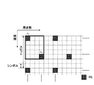
- a reference signal mapped discontinuously on the time / frequency axis as shown in FIG. 1 is used to measure SIR.
- RS reference signal
- E
- Interference power estimation method described above when the channel variation between the two reference channel variation value r 1 obtained from each signal, r c (thick frame in FIG. 1) is small, i.e., compared with the fluctuation period of the instantaneous fading Thus, when the reference signal is sufficiently close in time and frequency and the influence of fluctuations in instantaneous fading is limited, highly accurate interference power estimation can be performed. However, when the moving speed is high or the delay spread is large, the correlation of fading fluctuation between the channel fluctuation values r 1 and r c obtained from the two reference signals is low, and r 1 and r c There is an influence of fluctuation of instantaneous fading between them. At this time, in the above interference power estimation method, the accuracy of interference power estimation is greatly degraded. As a result, there is a problem that the SIR that is the reception quality cannot be accurately measured.
- the present invention has been made in view of such a point, and even when the correlation between fading fluctuations between reference signals is low, a receiving apparatus capable of accurately obtaining interference quality by performing interference power estimation with high accuracy
- Another object of the present invention is to provide an interference power estimation method.
- the receiving apparatus of the present invention includes a reference signal extraction unit that extracts a reference signal from a received signal including a plurality of reference signals that are discontinuous in the time / frequency plane and obtains a channel fluctuation value, and a specific signal in the time / frequency plane.
- Linear synthesizing means for linearly synthesizing channel fluctuation values respectively obtained from reference signals surrounding time / frequency reference signals with a predetermined weight, and interference power estimating means for estimating interference power using the linearly synthesized linearly synthesized values; It is characterized by comprising.
- the interference power estimation means estimates the interference power by averaging the difference between the linear composite value and the channel fluctuation value obtained from the specific time / frequency reference signal. It is preferable to obtain a value.
- the reference signal on the time / frequency plane is mapped to an arrangement used in the LTE system.
- the interference power estimation method of the present invention includes a step of receiving a signal including a plurality of reference signals that are discontinuous in a time / frequency plane, a step of obtaining a channel fluctuation value by extracting the reference signal from the signal, and the time A step of linearly synthesizing a channel variation value obtained from a reference signal surrounding a reference signal of a specific time / frequency in a frequency plane with a predetermined weight, and a step of estimating interference power using the linearly synthesized linearly synthesized value; It is characterized by comprising.
- this method it is possible to interpolate a fading fluctuation in a region partitioned by a reference signal surrounding a reference signal of a specific time / frequency on the time / frequency plane. As a result, even when the correlation of fading fluctuations between reference signals is low, interference power estimation can be performed with high accuracy, and as a result, accurate reception quality can be obtained.
- the difference between the linear composite value and the channel fluctuation value obtained from the specific time / frequency reference signal may be square-averaged to obtain an estimated interference power value. preferable.
- the reference signal in the time / frequency plane is mapped to an arrangement used in the LTE system.
- the channel fluctuation values obtained from RS 3 and RS 4 are r 1 , r 2 , r 3 and r 4 , respectively, and the reference signals RS 1 and RS 2 are separated from the reference signal RS c by 3 subcarriers and 4 symbols, respectively.
- a signal including a plurality of reference signals that are discontinuous in the time / frequency plane is received, the reference signal is extracted from the signal, and a reference signal having a specific time / frequency in the time / frequency plane is obtained. Since the surrounding reference signal is linearly synthesized with a predetermined weight and the interference power is estimated using the linearly synthesized linearly synthesized value, the interference power can be accurately detected even when the correlation of fading fluctuations between the reference signals is low. An accurate reception quality can be obtained by performing estimation.
- a signal including a plurality of reference signals that are discontinuous in the time / frequency plane is received, the reference signal is extracted from the signal, and a specific time / frequency in the time / frequency plane is obtained.
- the channel fluctuation values respectively obtained from the reference signals surrounding the reference signals are linearly synthesized with a predetermined weight, and the interference power is estimated using the linearly synthesized linearly synthesized values.
- a reference signal surrounding a specific time / frequency reference signal in the time / frequency plane is obtained by linearly synthesizing the reference signal surrounding the specific time / frequency reference signal in the time / frequency plane with a predetermined weight. It is possible to interpolate the fading fluctuation in the area partitioned by. As a result, even when the correlation of fading fluctuation between reference signals is low, interference power estimation can be performed with high accuracy.
- FIG. 2 is a diagram showing the arrangement of RSs in the downlink used in the LTE system.
- RSs are arranged every 6 subcarriers in the first and fifth symbols of each slot on the time / frequency plane.
- an area partitioned by four RSs that is, two RSs of each first symbol of a certain slot and a slot adjacent thereto and two RSs adjacent to each other in the frequency direction of the two RSs (
- the RS of the fifth symbol of the slot is located inside a region surrounded by a thick line in FIG.
- this RS arrangement there are four RSs, that is, two RSs of each fifth symbol of a certain slot and a slot adjacent thereto, and two RSs adjacent to each other in the frequency direction of the two RSs.
- the RS of the first symbol of the adjacent slot is located inside the partitioned area.
- the area composed of the four adjacent RSs in the first symbol of the slot overlaps the area composed of the four adjacent RSs in the fifth symbol of the slot. ing.
- channel fluctuation values r 2k + 1, l obtained from the received signal of the RS of the fifth symbol in the slot shown in FIG. 2 and the channels obtained from the received signals of the four RSs of the first symbol of the slots surrounding it.
- Interference power is estimated by interpolating fading fluctuations with the fluctuation values r 2k, l , r 2k, l + 1 , r 2 (k + 1), l , r 2 (k + 1), l + 1 as one unit to obtain the variance of the received signal.
- a process of interpolating fading fluctuation is performed in an area formed by four RSs adjacent to the first symbol or the fifth symbol of the slot. That is, the channel fluctuation values obtained from the received signals of the RSs surrounding the RS of a specific time / frequency in the time / frequency plane are linearly synthesized with a predetermined weight, and the RS of the specific time / frequency is linearly synthesized from the linearly synthesized linearly synthesized value.
- the channel fluctuation value obtained from the received signal is subtracted, the subtracted value after subtraction is averaged, and the average value after averaging is used as the estimated value of interference power. Further, the SIR is measured using the estimated value of the interference power.
- FIG. 3 is a diagram for explaining weighting at the time of linear synthesis in the present invention.
- a channel fluctuation value obtained from an RS of a specific time / frequency from the reference signal RS c is denoted by r c, and RS 1 , RS 2 , RS 3 , RS 4 that are four RSs surrounding the reference signal RS c. It is set to r 1, r 2, r 3 , r 4 channel fluctuation values obtained from each.
- the reference signal RS 1 is arranged a subcarrier and c symbols away from the reference signal RS c
- the reference signal RS 2 is arranged b b carriers and c symbols away from the reference signal RS c
- the reference signal RS 3 is the reference signal RS
- the reference signal RS 4 is arranged at a distance of b subcarriers and d symbols from the reference signal RS c .
- the interpolated channel fluctuation value r c ′ weighted according to the distances to the reference signals RS 1 , RS 2 , RS 3 , RS 4 is expressed by the following equation (1).
- r c ′ (bd ⁇ r 1 + ad ⁇ r 2 + bc ⁇ r 3 + ac ⁇ r 4 ) / ⁇ (a + b) (c + d) ⁇ Equation (1)
- the interference power is estimated using the interpolated channel fluctuation value r c ′.
- the interference power estimation value is obtained by normalizing the variance of the channel fluctuation value r c obtained from the interpolation channel fluctuation value r c ′ and RS c (the following equation (2)).
- 2 ) / X X 1 + [(a 2 + b 2 ) (c 2 + d 2 ) / ⁇ (a + b) (c + d) ⁇ 2 ]
- the reference signal of a specific time and frequency as the reference signal r c a reference signal which surrounds a reference signal r c a reference signal r 1, r 2, r 3 , r 4, a reference signal RS 1, RS 2
- the reference signal RS c is arranged 3 subcarriers and 4 symbols apart from each other, and the reference signals RS 3 and RS 4 are arranged 3 subcarriers and 3 symbols apart from the reference signal RS c , respectively.
- the interpolation reference channel fluctuation values r c ′ and X are as follows.
- the reference signal surrounding the reference signal RS c is interpolated with the reference signals RS 1 , RS 2 , RS 3 , RS 4 as a unit to interpolate the channel variation, and the average power and variance of the received reference signal are obtained,
- N L and N K are the numbers of RSs in the average interval in the frequency direction and the time direction, respectively.
- the interference power estimation method described above since the fading fluctuation in the region partitioned by the reference signal surrounding the reference signal of the specific time / frequency is interpolated in the time / frequency plane, the reference Even when the correlation between fading fluctuations between signals is low, interference power estimation can be performed with high accuracy, and as a result, accurate reception quality can be obtained.
- an RS of an RS used in the LTE system An arrangement area may be mentioned. That is, in the RS arrangement as shown in FIGS. 4 and 5, the area surrounded by the thick line is the interpolation area or the interpolation unit.
- the RS arrangement is as shown in FIG. 4
- the RS arrangement configuration (number of symbols and position) shown in FIG. 4 is determined from the viewpoint of channel estimation accuracy and overhead.
- FIG. 5 RS is mapped to the first symbol and the fifth symbol in each slot every six subcarriers for each antenna.
- the RSs for the third and fourth antennas are mapped to the same subcarrier as the first and second antennas, respectively, only in the second symbol in the slot.
- an RS arrangement as shown in FIG. 5 is obtained.
- the number of antennas is 1 or 2 (1 antenna port, 2 antenna ports), as shown in FIG. 2, RS is mapped to the first symbol and the fourth symbol in each slot every 6 subcarriers for each antenna. Is done.
- the RSs for the third and fourth antennas are mapped to the same subcarrier as the first and second antennas, respectively, only in the second symbol in the slot.
- FIG. 6 is a diagram showing a schematic configuration of a receiving apparatus according to the present invention.
- the mobile terminal device is a receiving device in the LTE system
- 6 includes a reception antenna 11, a reception unit 12, an FFT (Fast Fourier Transform) unit 13, an RS extraction unit 14, a weighting synthesis unit 15, a subtraction unit 16, and a square averaging unit. 17 is mainly composed.
- the mobile terminal apparatus also includes a transmission unit, which is omitted for the sake of simplicity.
- the receiving unit 12 receives the OFDM signal from the radio base station device via the receiving antenna 11.
- the receiving unit 12 outputs the OFDM signal to the FFT unit 13.
- the FFT unit 13 performs FFT on the OFDM signal and converts it to a frequency domain signal.
- the FFT unit 13 outputs the signal after the FFT to the RS extraction unit 14.
- the RS extraction unit 14 extracts the RS from the signal after the FFT. For example, the RS extraction unit 14 extracts reception signals corresponding to the reference signals RS c , RS 1 , RS 2 , RS 3 , and RS 4 in FIG. 3, and channel variation values r c , r 1 , r 2 , and r 3, respectively. , determine the r 4. The outputs channel fluctuation value r 1 to be used for weighting and combining, r 2, r 3, the r 4 to the weighting combining unit 15, and outputs channel fluctuation value r c to the subtraction unit 16.
- the weighting / synthesizing unit 15 uses the channel fluctuation values r 1 , r 2 , r 3 , and r 4 to obtain an interpolated channel fluctuation value r c ′ according to Equation (1).
- the RS arrangement shown in FIG. 4 or 5 is known in the mobile terminal apparatus.
- a, b, c, and d in FIG. 3 are also known on the mobile terminal device side from the RS arrangement.
- the weighting / synthesizing unit 15 obtains the interpolation reference signal r c ′ from the equation (1) using the reference signals r 1 , r 2 , r 3 , r 4 and a, b, c, d. it can.
- the weighting synthesis unit 15 outputs the interpolated channel fluctuation value r c ′ to the subtraction unit 16.
- Subtraction unit 16 RS and channel fluctuation value r c obtained from the reference signal extracted by the extraction section 14, 'the difference between (
- the subtraction unit 16 outputs the obtained difference to the square averaging unit 17.
- the square averaging unit 17 obtains an estimated value of interference power using the difference obtained by the subtracting unit 16. That is, the square averaging unit 17 obtains an estimated value of the interference power according to the equation (2). Also in this case, since a, b, c, and d in FIG. 3 are known on the mobile terminal device side, the square averaging unit 17 uses the difference and a, b, c, and d to obtain the formula (2 ) To obtain an estimated value of interference power.
- the average SIR can be obtained by the above formula (3) using the estimated interference power value obtained in this way.
- This SIR is highly accurate because the interference power is accurately estimated without being affected by fading fluctuations by the interference power estimation method according to the present invention.
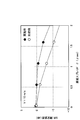
- the accuracy of SIR measurement was evaluated by computer simulation.
- the system bandwidth is 5 MHz
- the subcarrier interval is 15 kHz
- the number of subcarriers is 300.
- the transmitter of the radio base station apparatus time-multiplexes a 5-symbol pseudo-random data signal and 2-symbol RS in one slot of 0.5 msec length, and signals in the time domain by IFFT (Inverse Fast Fourier Transform). After conversion to CP, CP was added. Also, the FFT timing synchronization at the receiving unit on the mobile terminal device side is ideal.
- the interference power component was white Gaussian noise, and the average received SIR was fixed at 10 dB.
- r. m. s root mean square delay spread ⁇ ( ⁇ sec) and moving speed v (m / s) were used as parameters.
- the averaging period is the entire transmission signal band in the frequency direction, and the measurement is performed intermittently at a time rate of 10% while moving in the time direction by 30 meters. The results are shown in FIGS.
- An SIR measurement error obtained by using the interference power estimation method according to the present invention was taken as an example (black circle), and an SIR measurement error obtained by the conventional method shown in FIG. 1 was taken as a comparative example (white circle).
- the measurement error increases as the delay spread increases.
- the interference power can be accurately measured by interpolating the channel fluctuation in the frequency direction, the measurement error is relatively small.
- An SIR measurement error obtained by using the interference power estimation method according to the present invention was taken as an example (black circle), and an SIR measurement error obtained by the conventional method shown in FIG. 1 was taken as a comparative example (white circle).
- the average measurement error can be within 1 dB at a moving speed ⁇ 60 (m / s).
- the present invention is not limited to the above embodiment, and can be implemented with various modifications.
- a case has been described in which the downlink of the LTE system is assumed and the reception apparatus is a reception apparatus of a mobile terminal apparatus.
- the present invention is not limited to this, and OFDM transmission is performed for uplink transmission. Any system that applies transmission can be applied to a receiving apparatus of a radio base station apparatus.
- RS in the LTE system has been described in the above embodiment, the present invention is not limited to this, and can be applied regardless of the correlation of fading fluctuation between RSs. is there.
Landscapes
- Engineering & Computer Science (AREA)
- Computer Networks & Wireless Communication (AREA)
- Signal Processing (AREA)
- Mobile Radio Communication Systems (AREA)
- Monitoring And Testing Of Transmission In General (AREA)
Abstract
Description
rc’=(bd・r1+ad・r2+bc・r3+ac・r4)/{(a+b)(c+d)} 式(1)
そして、この補間チャネル変動値rc’を用いて、干渉電力の推定を行う。すなわち、補間チャネル変動値rc’とRScから求めたチャネル変動値rcの分散を正規化することにより干渉電力の推定値とする(下記式(2))。
E(|rc’-rc|2)/X
X=1+[(a2+b2)(c2+d2)/{(a+b)(c+d)}2] 式(2)
rc’=(3r1+3r2+4r3+4r4)/14
X=123/98
したがって、干渉電力の推定値は、rc’=(3r1+3r2+4r3+4r4)/14として、E(|rc’-rc|2)(Eはアンサンブル平均)の値に98/123を乗じた値となる。

Claims (8)
- 時間・周波数平面において不連続である複数の参照信号を含む受信信号から前記参照信号を取り出す参照信号抽出手段と、前記時間・周波数平面における特定の時間・周波数の参照信号を取り囲む参照信号からそれぞれ求めたチャネル変動値を所定の重み付けで線形合成する線形合成手段と、前記線形合成した線形合成値を用いて干渉電力を推定する干渉電力推定手段と、を具備することを特徴とする受信装置。
- 前記干渉電力推定手段は、前記線形合成値と前記特定の時間・周波数の参照信号から求めたチャネル変動値との間の差分を2乗平均して干渉電力の推定値を得ることを特徴とする請求項1記載の受信装置。
- 前記時間・周波数平面における参照信号は、LTEシステムで使用する配置にマッピングされていることを特徴とする請求項1記載の受信装置。
- 前記特定の時間・周波数の参照信号を参照信号RScから求めたチャネル変動値をrcとし、前記参照信号を取り囲む参照信号RS1,RS2,RS3,RS4からそれぞれ求めたチャネル変動値をr1,r2,r3,r4とし、前記参照信号RS1,RS2が前記参照信号RScからそれぞれ3サブキャリア、4シンボル離れて配置され、前記参照信号RS3,RS4が前記参照信号RScからそれぞれ3サブキャリア、3シンボル離れて配置されており、前記所定の重み付けがrc’=(3r1+3r2+4r3+4r4)/14であり、E(|rc’-rc|2)(Eはアンサンブル平均)の値に98/123を乗じた値を干渉電力の推定値とすることを特徴とする請求項1記載の受信装置。
- 時間・周波数平面において不連続である複数の参照信号を含む信号を受信する工程と、前記信号から前記参照信号を取り出す工程と、前記時間・周波数平面における特定の時間・周波数の参照信号を取り囲む参照信号からそれぞれ求めたチャネル変動値を所定の重み付けで線形合成する工程と、前記線形合成した線形合成値を用いて干渉電力を推定する工程と、を具備することを特徴とする干渉電力推定方法。
- 前記線形合成値と前記特定の時間・周波数の参照信号から求めたチャネル変動値との間の差分を2乗平均して干渉電力の推定値を得ることを特徴とする請求項5記載の干渉電力推定方法。
- 前記時間・周波数平面における参照信号は、LTEシステムで使用する配置にマッピングされていることを特徴とする請求項5記載の干渉電力推定方法。
- 前記特定の時間・周波数の参照信号RScから求めたチャネル変動値をrcとし、前記参照信号RScを取り囲む参照信号RS1,RS2,RS3,RS4から求めたチャネル変動値をr1,r2,r3,r4とし、前記参照信号RS1,RS2が前記参照信号RScからそれぞれ3サブキャリア、4シンボル離れて配置され、前記参照信号RS3,RS4が前記参照信号RScからそれぞれ3サブキャリア、3シンボル離れて配置されており、前記所定の重み付けがrc’=(3r1+3r2+4r3+4r4)/14であり、E(|rc’-rc|2)(Eはアンサンブル平均)の値に98/123を乗じた値を干渉電力の推定値とすることを特徴とする請求項5記載の干渉電力推定方法。
Priority Applications (2)
| Application Number | Priority Date | Filing Date | Title |
|---|---|---|---|
| US13/391,697 US20120178393A1 (en) | 2009-08-24 | 2010-08-12 | Receiving apparatus and interference power estimation method |
| CN201080037626XA CN102484891A (zh) | 2009-08-24 | 2010-08-12 | 接收装置和干扰功率估计方法 |
Applications Claiming Priority (2)
| Application Number | Priority Date | Filing Date | Title |
|---|---|---|---|
| JP2009-193534 | 2009-08-24 | ||
| JP2009193534A JP5016006B2 (ja) | 2009-08-24 | 2009-08-24 | 受信装置及び干渉電力推定方法 |
Publications (1)
| Publication Number | Publication Date |
|---|---|
| WO2011024649A1 true WO2011024649A1 (ja) | 2011-03-03 |
Family
ID=43627755
Family Applications (1)
| Application Number | Title | Priority Date | Filing Date |
|---|---|---|---|
| PCT/JP2010/063682 Ceased WO2011024649A1 (ja) | 2009-08-24 | 2010-08-12 | 受信装置及び干渉電力推定方法 |
Country Status (4)
| Country | Link |
|---|---|
| US (1) | US20120178393A1 (ja) |
| JP (1) | JP5016006B2 (ja) |
| CN (1) | CN102484891A (ja) |
| WO (1) | WO2011024649A1 (ja) |
Families Citing this family (5)
| Publication number | Priority date | Publication date | Assignee | Title |
|---|---|---|---|---|
| JP5753808B2 (ja) * | 2012-03-16 | 2015-07-22 | 株式会社Nttドコモ | 無線通信システムの評価装置 |
| KR20160057423A (ko) * | 2013-09-30 | 2016-05-23 | 후지쯔 가부시끼가이샤 | 신호 측정 방법, 사용자 장비, 및 기지국 |
| WO2015069811A1 (en) * | 2013-11-06 | 2015-05-14 | Mediatek Singapore Pte. Ltd. | Reception failure feedback scheme in wireless local area networks |
| CN114421994B (zh) * | 2022-01-05 | 2023-07-25 | 西安信电装备工程中心有限公司 | 轨道交通车辆差分总线干扰抑制方法 |
| CN115883002A (zh) * | 2022-12-23 | 2023-03-31 | 中国电子科技集团公司第五十四研究所 | 一种功率自动调整的上行tdma信号干扰方法 |
Family Cites Families (7)
| Publication number | Priority date | Publication date | Assignee | Title |
|---|---|---|---|---|
| CN101496325B (zh) * | 2006-07-25 | 2012-07-04 | 富士通株式会社 | 多载波通信系统中的干扰噪声估计方法和接收处理方法以及干扰噪声估计装置和接收机 |
| US8213943B2 (en) * | 2007-05-02 | 2012-07-03 | Qualcomm Incorporated | Constrained hopping of DL reference signals |
| JP2009065403A (ja) * | 2007-09-06 | 2009-03-26 | Nec Corp | 無線通信における受信品質推定方法および装置 |
| US8514975B2 (en) * | 2008-08-21 | 2013-08-20 | Lg Electronics Inc. | Method and apparatus for transmitting reference signal in wireless communication system |
| US20100184380A1 (en) * | 2009-01-20 | 2010-07-22 | Qualcomm Incorporated | Mitigating intercarrier and intersymbol interference in asynchronous wireless communications |
| US8953563B2 (en) * | 2009-04-24 | 2015-02-10 | Samsung Electronics Co., Ltd. | Method and system for multi-layer beamforming |
| US8385833B2 (en) * | 2009-04-30 | 2013-02-26 | Telefonaktiebolaget L M Ericsson (Publ) | Adaptive idle mode measurement methods and apparatus |
-
2009
- 2009-08-24 JP JP2009193534A patent/JP5016006B2/ja not_active Expired - Fee Related
-
2010
- 2010-08-12 US US13/391,697 patent/US20120178393A1/en not_active Abandoned
- 2010-08-12 CN CN201080037626XA patent/CN102484891A/zh active Pending
- 2010-08-12 WO PCT/JP2010/063682 patent/WO2011024649A1/ja not_active Ceased
Non-Patent Citations (1)
| Title |
|---|
| "IEICE Communications Society Conference 2008 Koen Ronbunshu 1", 2 September 2008, ISSN: 1349-1415, article MOTOTSUGU SUZUKI ET AL.: "A Study on SIR Measurement Method using RS for Service Area Estimation in LTE System", pages: 24 * |
Also Published As
| Publication number | Publication date |
|---|---|
| JP2011045027A (ja) | 2011-03-03 |
| US20120178393A1 (en) | 2012-07-12 |
| JP5016006B2 (ja) | 2012-09-05 |
| CN102484891A (zh) | 2012-05-30 |
Similar Documents
| Publication | Publication Date | Title |
|---|---|---|
| US11695672B2 (en) | Communication system determining time of arrival using matching pursuit | |
| JP2024084752A (ja) | マルチキャリア位相ベース定位のためのシステムおよび方法 | |
| JP5939824B2 (ja) | 移動通信システムのオフセット推定方法及び装置 | |
| US7852909B2 (en) | Method and apparatus for estimating frequency offset and timing offset of one or more mobile stations (MSs) | |
| WO2010142692A1 (en) | Rf fingerprinting for location estimation | |
| CN113423061B (zh) | 对处于5g网络下的终端设备的定位方法和装置 | |
| CN105024951B (zh) | 一种功率时延谱pdp估计方法及装置 | |
| KR20090033399A (ko) | 멀티 캐리어 통신 시스템에서의 간섭 잡음 추정 방법 및 수신 처리 방법과 간섭 잡음 추정 장치 및 수신기 | |
| JP5016006B2 (ja) | 受信装置及び干渉電力推定方法 | |
| CN112585874B (zh) | 用于信号检测的本底噪声估计 | |
| CN108989259B (zh) | 无线综测仪窄带物理上行共享信道的时偏估计方法及系统 | |
| CN117320046A (zh) | Crs搜索方法、lte时间对齐误差测定方法和用户设备 | |
| WO2011137631A1 (zh) | 测距码检测方法和装置 | |
| US7719954B2 (en) | Apparatus and method for measuring noises in a wireless communication system | |
| Suárez-Casal et al. | Experimental assessment of WiMAX transmissions under highly time-varying channels | |
| CN106850483B (zh) | 一种用于无线通信系统的相位误差估计方法及装置 | |
| CN110602014B (zh) | 基于lte下行参考信号的采样时刻偏差估计方法 | |
| CN111211850B (zh) | 噪声估计方法、装置、基站设备和计算机可读存储介质 | |
| JP5099124B2 (ja) | 無線通信品質推定方法及び装置 | |
| US9769687B2 (en) | Method and related mobile device for determining a reference signal received power | |
| US12335004B2 (en) | Sounding reference signal beamformer enhancement with timing correction | |
| CN103188182B (zh) | 基于快变多普勒信道的频谱估计方法及装置 | |
| CN102223335A (zh) | 一种时偏估计方法和装置 | |
| CN101662446A (zh) | 信道估计方法及装置 | |
| WO2007075073A1 (en) | Apparatus and method for estimating channel in communication system supporting ofdm/ofdma |
Legal Events
| Date | Code | Title | Description |
|---|---|---|---|
| WWE | Wipo information: entry into national phase |
Ref document number: 201080037626.X Country of ref document: CN |
|
| 121 | Ep: the epo has been informed by wipo that ep was designated in this application |
Ref document number: 10811699 Country of ref document: EP Kind code of ref document: A1 |
|
| NENP | Non-entry into the national phase |
Ref country code: DE |
|
| WWE | Wipo information: entry into national phase |
Ref document number: 13391697 Country of ref document: US |
|
| 122 | Ep: pct application non-entry in european phase |
Ref document number: 10811699 Country of ref document: EP Kind code of ref document: A1 |