WO2011024314A1 - 状態遷移検証装置およびその方法 - Google Patents
状態遷移検証装置およびその方法 Download PDFInfo
- Publication number
- WO2011024314A1 WO2011024314A1 PCT/JP2009/065209 JP2009065209W WO2011024314A1 WO 2011024314 A1 WO2011024314 A1 WO 2011024314A1 JP 2009065209 W JP2009065209 W JP 2009065209W WO 2011024314 A1 WO2011024314 A1 WO 2011024314A1
- Authority
- WO
- WIPO (PCT)
- Prior art keywords
- state
- classification
- transition
- states
- state set
- Prior art date
- Legal status (The legal status is an assumption and is not a legal conclusion. Google has not performed a legal analysis and makes no representation as to the accuracy of the status listed.)
- Ceased
Links
Images










Classifications
-
- G—PHYSICS
- G06—COMPUTING OR CALCULATING; COUNTING
- G06F—ELECTRIC DIGITAL DATA PROCESSING
- G06F11/00—Error detection; Error correction; Monitoring
- G06F11/28—Error detection; Error correction; Monitoring by checking the correct order of processing
Definitions
- the present invention relates to a state transition verification apparatus and method for verifying compatibility between a state transition system and verification contents in a system design process such as software.
- Verification of compatibility between state transition system and verification contents is to verify whether the state transition system that represents the behavior of the design target system satisfies the verification contents that are the specifications of the system.
- the state transition system satisfies the verification content, if any condition of the state transition system satisfies the pre-condition Pre, it must transition to a state that satisfies the post-condition Post after the event Event occurs. is there. At this time, the verification content is premised on the occurrence of the event Event in any state that satisfies the precondition Pre.
- the difference set P-WP is calculated to verify the compatibility, and if the P-WP is an empty set, the state transition system satisfies the verification contents. If the P-WP is not an empty set, the P-WP Output the element as a counterexample.
- the present invention provides a state transition verification apparatus and method for generating and outputting information capable of easily grasping the characteristics of a state causing a nonconformity.
- the state transition verification device of the present invention is First to input a state transition system defined by a plurality of states defined by combinations of values of one or more internal variables, a plurality of events, and a state transition caused by the occurrence of each event Input means;
- a second input means for inputting verification contents defined by a set of post-conditions that the value should satisfy,
- First search means for searching from the state transition system the state set P that satisfies the pre-conditions;
- a second search unit that searches the state transition system for a state set WP that transitions to a transition destination state that satisfies the posterior condition when the one event occurs;
- Classification table generation means for generating a classification table that describes all internal variables of all the states and whether or not they belong to the state set P and the state set WP with respect to all the states of
- classification table Using the classification table, generate a classification tree that classifies all the states into the state set P and the presence / absence of the state set WP based on the values of internal variables included in all the states.
- State classification means; In the classification tree, a leaf node indicating that it belongs to the state set P and does not belong to the state set WP is assigned a label indicating incompatibility with the verification content, and the classification tree to which the label is assigned is output. 1 output means, Is provided.
- FIG. 6 is a diagram illustrating a precondition set P according to the first embodiment.
- 10 is a detailed flowchart of process 2 according to the first embodiment.
- FIG. 6 is a diagram for explaining event filter processing according to the first embodiment.
- FIG. 6 is a diagram for explaining post-condition filtering processing according to the first embodiment.
- FIG. 10 is a diagram illustrating the weakest precondition set WP according to the first embodiment.
- FIG. 3 is a diagram showing a classification table according to the first embodiment.
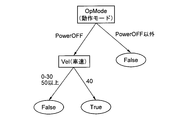
- FIG. 3 is a diagram illustrating a classification tree according to the first embodiment.
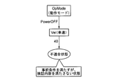
- FIG. 4 is a diagram illustrating an output example according to the first embodiment.
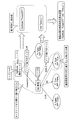
- 9 is a flowchart showing an overall processing flow according to the second embodiment.
- FIG. 10 is a diagram illustrating a classification table according to the second embodiment.
- FIG. 10 is a diagram illustrating a classification tree according to the second embodiment.
- FIG. 10 is a diagram illustrating an output example according to the second embodiment.
- 10 is a flowchart showing an overall processing flow according to the third embodiment.
- FIG. 20 is a view for explaining process 5 of FIG.
- Cruise controller is a type of vehicle control system that automatically maintains a constant vehicle speed without stepping on the accelerator pedal.
- the throttle opening is adjusted appropriately with respect to the current vehicle speed. For example, if the current vehicle speed is slower than the target vehicle speed, the throttle opening is increased. If the acceleration button is pressed, the target vehicle speed is added by a certain amount.
- the cruise controller holds a plurality of internal variables representing the current vehicle speed, the target vehicle speed, etc. in order to realize these functions. Also, for various events such as pressing the acceleration button, a process of updating the internal variable is executed as defined.
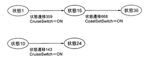
- Fig. 21 shows a part of the state transition system of the cruise controller.
- the state transition system is a comprehensive description of the behavior of the target system (here, the cruise controller). It is a state that is a snapshot of all internal variable values held by the system, and the state transitions that occur when various events occur. It is defined as a certain state transition.
- a circle represents a state
- an arrow connecting two states represents a state transition.
- State 15 is an internal variable OpMode (operation mode) “Standby”, CRNE (target vehicle speed) is 0, Vel (vehicle speed) is 130, and CruiseLamp (cruise ramp) is “ON”.
- OpMode (operation mode) changes from “PowerOFF” to “Standby”
- CruiseLamp cruise lamp
- State 10 the internal variable OpMode (operation mode) is “PowerOFF”, OFFCRNe (target vehicle speed) is 0, Vel (vehicle speed) is 40, and CruiseLamp (cruise lamp) is “OFF”.
- the state transits to another state 24 (state transition 143).
- State 24 is a state in which the internal variable OpMode (operation mode) is “PowerOFF”, CRNe (target vehicle speed) is 0, Vel (vehicle speed) is 40, and CruiseLamp (cruise lamp) is “OFF”.
- this verification content satisfies the pre-condition Pre, it is requested to transition to a state satisfying the post-condition Post after the event Event occurs.
- the verification content is premised on the occurrence of the event Event in any state that satisfies the precondition Pre.
- State 1 in FIG. 21 satisfies the precondition, and after the occurrence of the event “CruiseSwitchON”, the state transitions to state 15 by the state transition 359. Therefore, state 1 satisfies the verification content.
- the state set P satisfying the precondition Pre and the state set WP satisfying the weakest precondition WP (Event, Post) are calculated, and the difference set P-WP is calculated. It is done by asking.
- the difference set P-WP is a set of a state that transitions to a state that satisfies the precondition but does not satisfy the postcondition after the occurrence of the event, and a state that satisfies the precondition but does not generate the event. If the difference set P-WP is not an empty set, the difference set P-WP is output as a state set as a counterexample of verification.
- state 10 is one of the counterexamples that do not satisfy the verification content.
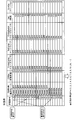
- FIG. 22 shows an example of the output result of the counter example state set.
- the first column of the table is the state number that uniquely identifies the state, and the second and subsequent columns are the values of each internal variable of the state. From this table, it is difficult to grasp the characteristics of the state of the difference set P-WP, that is, what value of the internal variable the state does not satisfy the verification content. In actual product development, the number of counter-examples and the number of internal variables are further increased, and the problem becomes more serious.
- the present invention is intended to solve such a problem so that the characteristics of the state of the difference set P-WP can be easily grasped.
- FIG. 1 is a block diagram showing a configuration of a state transition verification device according to an embodiment of the present invention.
- This state transition verification device includes a first input unit 11 for inputting a state transition system, a second input unit 12 for inputting verification content data, a precondition search unit (first search unit) 13, and a weakest precondition search unit.
- (Second search means) 14 classification table generation means 15, state classification means 16, classification result output means (first output means) 17, feature quantity extraction means (extraction means) 18, nonconforming content output means (second output means) ) 19, verification content correction candidate determination means (acquisition means) 20, and verification content correction candidate output means (third output means) 21.
- the feature quantity extraction means 18 and the nonconformity content output means 19 are elements mainly related to the third embodiment, and the verification content correction candidate determination means 20 and the verification content correction candidate output means 21 are mainly related to the fourth embodiment. Since these are elements, these elements will not be described in this embodiment, but will be described in the respective embodiments 3 and 4.
- the first input means 11 reads a state transition system defined by the state table and the state transition table from, for example, a memory, a hard disk, an optical disk, etc., and inputs it to the apparatus.
- the state table includes an identifier (state number) of each state and variable values of all internal variables.
- An example of the state table is shown in FIG. For example, in state 1, the internal variable OpMode (operation mode) is “PowerOFF”, CRNe (target vehicle speed) is 0, CruiseLamp (cruise ramp) is “OFF”, SetLamp (set ramp) is “OFF”, CruiseSwitch (cruise switch) Is “OFF”, Vel (vehicle speed) is 130, and Throttle (throttle) is 0.
- the initial state is state 0.
- the state transition table includes an identifier (transition number) of each state transition, a state identifier of the state transition source (transition source), a state identifier of the state transition destination (transition destination), and the content of the transition (event).
- An example of the state transition table is shown in FIG.
- the state transition 23 (transition number) in the state transition table is a transition due to the event “CruiseSwitchOn”, and transitions to the state 14 when the event occurs in the state 0.
- the second input means 12 reads the data of the verification content defined by the combination of the precondition Pre, the event Event, and the postcondition Post from a recording medium such as a memory, a hard disk, or an optical disk and inputs it.
- the precondition is a conditional expression that the value of the internal variable of the transition source state should satisfy
- the event Event is one of the events included in the state transition system
- the post condition is the event Event that occurred in the transition source state This is a conditional expression that the value of the internal variable of the transition destination state should satisfy.
- the precondition search means (first search means) 13 reads the state table and the preconditions of the verification contents, and searches for the state set P of the state transition system that satisfies the preconditions of the verification contents.
- the retrieved state set P is output to the classification table generating means 15.
- the precondition search unit 13 may include a reading unit that reads data from the state transition system storage unit 11 and a reading unit that reads data from the verification content storage unit 12.
- the weakest precondition search means (second search means) 14 reads the state table, the state transition table, the event of the verification content and the postcondition, and the weakest precondition of the verification content (the post-event when the event occurs) A state set WP of a state transition system that satisfies a necessary and sufficient condition of a state transitioning to a state satisfying a condition) is searched.
- the weakest precondition retrieval unit 14 outputs the retrieved state set WP to the classification table generation unit 15.
- the classification table generation means 15 is based on the state table, state set P, and state set WP, and belongs to all internal variables of the state and state set P and state set WP respectively for all states of the state transition system. A classification table describing the presence / absence is generated. The classification table generation unit 15 outputs the classification table to the state classification unit 16.
- the state classification unit 16 uses the classification table generated by the classification table generation unit 15 to generate a classification tree that classifies each state into whether or not it belongs to the state set P, WP based on its internal variable value.
- Arbitrary known algorithms can be used to generate a classification tree, for example, an ID3 algorithm (J.R, Quinlan, “Induction of DecisionsTrees”, Chap. 4 “ID3”, 1986) can be used. With this ID3, the expected value of the average information amount when calculating whether the state set P and state set WP belong for each internal variable of the state is calculated, and the internal variable that maximizes the average information amount is selected. , Recursively make the tree a node.
- the classification result output means (first output means) 17 labels the leaf node indicating the classification that both the state sets P and WP belong in the classification tree with “conformity state” meaning the state that matches the verification contents. Label a leaf node indicating that it belongs to the state set P but does not belong to the state set WP with a “non-conforming state” meaning a state that does not match the verification contents, and classify that it does not belong to the state set P Is labeled “unrelated” which means a state unrelated to the verification contents.
- the classification result output means 17 outputs the labeled classification tree.
- the classification tree may be output to an output interface such as a display device or a printer and presented to the user.
- the apparatus may further include a storage device that stores the classification tree.
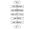
- FIG. 4 is a flowchart of the overall processing of the apparatus according to the first embodiment.
- Step1 Provides 1: Precondition search
- the precondition search means 13 reads the state table of FIG. 2 and the above-described verification contents (preconditions), and searches the state transition system state set P that satisfies the preconditions of the verification contents.
- state 0 is not included in state set P because it does not satisfy the precondition
- state 1 is included in state set P because it satisfies the precondition.
- the precondition search means 13 outputs the precondition state set P thus obtained to the classification table generation means 15.
- Step2 Provides the weakest precondition search means 14 reads the state table and state transition table of FIG. 2 and the above verification content (event, postcondition), and obtains the state set WP of the state transition system that satisfies the weakest precondition of the verification content. Search for.
- Fig. 6 shows the detailed flow of this process.
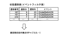
- Process 2-1 obtains a state transition table (after event filtering) in which only transitions (rows) including the verification event are extracted from the state transition table. For example, as shown in FIG. 7, the state transitions 0 to 22 are not extracted because these events are different from the verification event “Event” “CruiseSwitchON”. On the other hand, the state transition 23 is extracted because this event coincides with the event (CruiseSwitchON) of the verification content. In this way, the state transition table (after event filtering) shown on the right side of FIG. 7 is obtained.
- the state transition table (after post-condition filter) that extracts only the transitions (rows) having the transition destination that satisfies the post-condition of the verification content obtain.
- the transition destination state 23 of the state transition 167 is extracted to satisfy the post condition (Post) of the verification content.
- state transitions 191 and 215 are extracted. In this way, the state transition table (after the post-condition filter) shown on the right side of FIG. 8 is obtained.
- the state number of the transition source is acquired from all the state transitions in the state transition table (after the post-condition filter), and is a set of the acquired state numbers.
- the weakest precondition set WP ⁇ 7, 8, 9,.
- the weakest precondition search means 14 outputs the weakest precondition set WP thus obtained to the classification table generation means 15.
- Step3 Process 3: Generate classification table
- the classification table generating means 15 includes all the internal variables of the state for all the states in the state transition system. Then, a classification table describing the precondition state set P and the presence / absence of belonging to the state set WP is generated. The generated classification table is shown in FIG.
- the classification table in FIG. 10 includes all items in the state table (state number, all internal variables), items indicating whether or not they belong to the precondition state set P, and items indicating whether or not they belong to the weakest precondition state set WP. have. For example, since the state 0 does not include both the state sets P and WP, both items are “FALSE”. Since state 1 is included in both state sets P and WP, both items are “TRUE”. Since the state 10 is included in the state set P and not included in the WP, the affiliation to the precondition set P is “TRUE” and the affiliation to the weakest precondition set WP is “FALSE”.
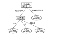
- Step4 (Process 4: State classification) Based on the classification table of FIG. 10, the state classification means 16 generates a classification tree for classifying the state set into whether or not it belongs to the precondition set P and the weakest precondition set WP.
- the generated classification tree is shown in FIG.
- a leaf node of the classification tree indicates whether or not it belongs to the precondition set P and the weakest precondition set WP. Nodes other than the leaf node (top node, intermediate node) correspond to one of a plurality of internal variables, and are child nodes.
- the branch extending to is the value that the internal variable can take.
- the leaf node represents a classification result (whether or not belonging to P, WP) for an internal variable value represented by a path uniquely determined from the top node.
- a state where the OpMode (operation mode) is “PowerOFF” and the Vel (vehicle speed) is 50 or more is determined to belong to both the precondition set P and the weakest precondition set WP.
- a state in which the OpMode (operation mode) is “PowerOFF” and the Vel (vehicle speed) is 40 belongs to the precondition set P, but is determined not to belong to the weakest precondition set WP.
- Step5 (Process 5: Classification result output)
- the classification result output means 17 is the classification tree of FIG. 11, the “adapted state” label is assigned to the leaf node whose affiliation to the state sets P and WP is “TRUE”, and the affiliation to the state set P is “TRUE”.
- a “non-conforming state” label is attached to a leaf node whose affiliation to the state set WP is “FALSE”
- an “irrelevant” label is attached to a leaf node affiliation to the state set P is “FALSE”.
- the classification tree labeled in this way is shown in FIG. Note that leaf nodes whose affiliation to the state set P is “FALSE” include both those whose affiliation to the state set WP is “True” and those that are “False”. In the example of FIG. 11, only the latter exists.
- this classification tree has the state set as conforming state (state belonging to both state set P and state set WP), nonconforming state (state belonging to state set P but not belonging to state set WP), unrelated (state set P State not belonging to).
- the nonconforming state is an element of the difference set P-WP, and the difference set P-WP is also referred to as a nonconforming state set.
- the fact that the nonconforming state set is not an empty set means that a state incompatible with the verification content exists.
- a state in which the OpMode (operation mode) is “PowerOFF” and the Vel (vehicle speed) is 50 or more is determined as a conformity state, that is, a state that satisfies the preconditions and satisfies the verification contents. Further, a state in which the OpMode (operation mode) is “PowerOFF” and the Vel (vehicle speed) is 40 is determined as a non-conforming state, that is, a state in which the pre-condition is satisfied but the verification content is not satisfied. The states other than those do not satisfy the preconditions and are determined to be irrelevant to the verification contents. Regarding these classifications, it can also be confirmed that internal variables other than OpMode (operation mode) and Vel (vehicle speed) are irrelevant to the verification contents.
- the classification result output means 17 outputs the labeled classification tree to an output interface or the like and presents it to the user.
- the user can refer to the internal variables and variable values on the path from the top node to the leaf node indicating the nonconforming state, in particular, the nonconforming content (internal variables and variables common to the nonconforming state). Value combinations) can be easily grasped.
- a list of non-conformance states was simply output, but in this embodiment, the classification tree that classifies states into conformity states and non-conformance states is visually displayed, so that the contents of nonconformity can be easily visualized. I can grasp.
- the second embodiment is characterized in that it generates and outputs a classification tree that includes only classification into non-conforming state and omits classification into other states (conforming state and irrelevant state). It is intended to make it easier to understand.
- the apparatus configuration of the second embodiment relates to the same elements 11 to 17 as in FIG. Hereinafter, the description will be focused on differences from the first embodiment, and the description overlapping with the first embodiment will be omitted.
- the classification table generating means 15 Based on the state table and the state sets P and WP, the classification table generating means 15 has all the internal variables of the state and the condition “belongs to the state set P and does not belong to the state set WP for all states in the state transition system. Is generated (TRUE ⁇ or ⁇ FALSE).
- the state classification means 16 generates a classification tree for classifying the presence / absence of belonging to the state set P and not belonging to the state set WP based on the classification table.
- the classification result output means 17 attaches a non-conforming state label to a leaf node indicating “TRUE” (belonging to the state set P and not belonging to the state set WP) in this classification tree. Then, all leaf nodes indicating “FALSE” and edges connecting the leaf node and its parent node are deleted. Further, an operation for deleting a non-leaf node having no child node (a node other than the leaf node) and an edge connecting the non-leaf node and the parent node is continued until there is no non-leaf node having no child node. repeat. The classification result output means 17 outputs the classification tree obtained in this way.
- FIG. 13 is a flowchart of the overall processing of the apparatus according to the second embodiment. Most of the processing is the same as in Example 1. Processing different from that in the first embodiment is indicated by hatched blocks in FIG. Step 1 ⁇ (processing 1: precondition search) and Step2 ⁇ (processing 2: weakest precondition search) are the same as in the first embodiment. Here, Step 3 and subsequent steps will be described.
- Step3 (Process 3: Generate classification table) Based on the sets P and WP obtained in Step 2, the classification table generation means 15 determines whether or not the condition “belongs to the state set P and belongs to the state set WP” is satisfied for all states of the state table, and the determination result By adding the item (TRUE or FALSE) to the state table, the classification table shown in FIG. 14 is obtained.
- the classification table of FIG. 14 is an item indicating whether all items (state number, all internal variables) of the state table (FIG. 2) and whether or not the condition “belongs to state set P and does not belong to state set WP” is satisfied. have. For example, state 0 is “FALSE” because neither state set P nor WP is included. Since state 1 includes both state sets P and WP, it becomes “FALSE”. Similarly, states 2 to 9 are “FALSE”. Since the state 10 is included in the state set P and not included in the state set WP, it becomes “TRUE”.
- Step4 Process 4: State classification
- the state classification means 16 generates a classification tree that classifies the state set into the presence / absence of the condition “belongs to the state set P and does not belong to the state set WP” from the classification table obtained in Step 3 (FIG. 14).
- the generated classification tree is shown in FIG. A state in which the OpMode (operation mode) is “Power OFF” and the Vel (vehicle speed) is 40 is determined to satisfy this condition (TRUE), and the other states are determined not to satisfy the condition (FALSE).
- Step5 Classification result output
- Classification result output means 17 in the classification tree obtained in Step 5 (Fig. 15) to the leaf node indicating "TRUE” (condition “belonging to state set P and not to state set WP"), state transition system and A non-conformance status label indicating non-conformance of the verification content is attached.
- all leaf nodes indicating “FALSE” and edges connecting the leaf node and its parent node are deleted.
- the classification tree shown in FIG. 16 is obtained.
- the second embodiment by outputting a classification tree including only the classification to the nonconforming state, it is possible to more easily grasp the nonconforming content (combination of internal variables and variable values that characterize the nonconforming state). .
- the third embodiment outputs nonconformity content (a combination of an internal variable of a state and a value of each internal variable) that is a feature of a nonconforming state (a state belonging to the state set P and not belonging to the state set WP). It is intended to make it easier to grasp the nonconformity content.
- the apparatus configuration of the third embodiment relates to the elements 11 to 16, 18, and 19 in FIG. 1, and uses the feature amount extraction means 18 and the nonconforming content output means 19 and does not use the classification result output means 17. Very different from 1.
- description will be made centering on differences from the first embodiment, and description of portions overlapping with the first embodiment will be omitted.
- the feature quantity extraction means (extraction means) 18 is a leaf node indicating a classification from the top node of the classification tree generated by the state classification means 16 to a nonconforming state (a state belonging to the state set P and not belonging to the state set WP).
- An internal variable that characterizes the nonconforming state by obtaining a combination of all the non-leaf nodes (top node, intermediate node) that exist on the path that uniquely connects the nodes and the label (value) of the edge directly under each non-leaf node And combination of variable values (contents of nonconformity).
- Non-conforming content output means (second output means) 19 outputs the non-conforming content obtained by the feature quantity extracting means 18.
- the nonconforming content is presented to the user via an output interface, for example.
- FIG. 17 is a flowchart of the overall processing of the apparatus according to the third embodiment. Most of the processing is the same as in Example 1. Processing different from that in the first embodiment is indicated by hatched blocks in FIG. Step 1 (Process 1: Precondition Search) to Step 4 ⁇ (Process 4: State Classification) are the same as in the first embodiment. Here, Step 5 and subsequent steps will be described.
- Step5 Process 5: Feature extraction
- the feature quantity extraction means 18 performs a feature quantity extraction process on the classification tree of FIG. FIG. 18 shows an example of the processing contents.
- a path that uniquely connects the leaf node indicating the classification from the top node at the top to the incompatible state at the bottom is surrounded by a dotted line.
- a combination of internal variables and variable values (OpMode, “PowerOFF”) is obtained from node “OpMode (operation mode)” and edge “PowerOFF” immediately below node 1.
- a combination of internal variables and variable values (Vel, 40) is obtained from node 2 “Vel (vehicle speed)” on the path and edge “40” immediately below node 2.
- Step6 Process 6: Output nonconformity content
- the combination of internal variables and variable values (nonconformity content) that characterizes the nonconformity state is output, thereby making it easier to grasp the nonconformity content.
- the fourth embodiment is characterized by detecting and outputting correction candidates for the preconditions of the verification content, focusing on the possibility that the verification content (specification) is incorrect.
- the preconditions that are correction candidates are expressed in the same format as the nonconformity contents of the third embodiment, that is, by a set of state internal variables and values of the respective internal variables.
- the apparatus configuration of the third embodiment relates to the elements 11 to 16, 20, and 21 of FIG. 1, uses the verification content correction candidate determination means 20, the verification content correction candidate output means 21, and does not use the classification result output means 17. This is very different from Example 1.
- description will be made centering on differences from the first embodiment, and description of portions overlapping with the first embodiment will be omitted.
- the verification content correction candidate determination means (acquisition means) 20 is a classification tree generated by the state classification means 16 and all non-leaf existing on the path that uniquely connects the leaf node indicating the affiliation to the state set WP from the top node. By obtaining a combination of the node (top node, intermediate node) and the label (value) of the edge immediately below the non-leaf node, a correction candidate for the precondition of the verification content is acquired.
- the leaf nodes indicating the affiliation to the state set WP include both those of “True” and “False” that belong to the state set P.
- the verification content correction candidate output means (third output means) 21 outputs the verification content correction candidates obtained by the verification content correction candidate determination means 20.
- the correction candidate for the verification content may be presented to the user via an output interface, for example.
- the use of this correction candidate is expected to eliminate the nonconformity.
- FIG. 19 is a flowchart of the overall processing of the apparatus according to the fourth embodiment. Most of the processing is the same as in Example 1. The processing different from that in the first embodiment is indicated by hatched blocks in FIG. Step 1 (Process 1: Precondition Search) to Step 4 ⁇ (Process 4: State Classification) are the same as in the first embodiment. Here, Step 5 and subsequent steps will be described.
- Step5 (Process 5: Verification content modification candidate decision)
- the verification content correction candidate determination means 20 performs processing on the classification tree of FIG. FIG. 20 shows an example of processing contents.
- the path that uniquely connects the leaf node indicating the affiliation to the weakest precondition WP at the bottom from the top node at the top is surrounded by a dotted line.
- the combination of the internal variable and the variable value (OpMode, “PowerOFF”) is obtained from the node 1 “OpMode (operation mode)” and the edge “PowerOFF” immediately below the node 1.
- a combination of internal variables and variable values (Vel, “50 or more”) is obtained from node 2 “Vel (vehicle speed)” on the path and an edge “50 or more” immediately below node 2.
- Step6 (Process 6: Verification content correction candidate output)
- the verification content correction candidate output means 21 outputs the correction candidate “OpMode:“ PowerOFF ”, Vel:“ 50 or more ”” obtained by the verification content correction candidate determination means 20.
- the state transition verification in FIG. 1 can also be realized by using, for example, a general-purpose computer device as basic hardware. That is, each element provided in the apparatus of FIG. 1 may be realized by causing a computer to execute a program describing an instruction to perform processing of each element. At this time, the state transition verification device may be realized by installing the above program in a computer device in advance, or may be stored in a storage medium such as a hard disk, a memory device, or an optical disk, or may be realized via a network. You may implement
Landscapes
- Engineering & Computer Science (AREA)
- Theoretical Computer Science (AREA)
- Quality & Reliability (AREA)
- Physics & Mathematics (AREA)
- General Engineering & Computer Science (AREA)
- General Physics & Mathematics (AREA)
- Stored Programmes (AREA)
Abstract
[課題]不適合を発生する状態の特徴を容易に把握する。 [解決手段]本発明の装置は、1つ以上の内部変数の値の組合せで定義される複数の状態と、複数のイベントと、イベントの発生に起因して生じる状態遷移とを含む状態遷移系を入力する手段と、事前条件とイベントと事後条件との組により定義される検証内容を入力する手段と、事前条件を満たす状態集合Pを状態遷移系から検索する手段と、検証内容のイベントが発生したときに事後条件を満たす遷移先状態に遷移する状態集合WPを状態遷移系から検索する手段と、状態遷移系の全ての状態の各々に関して、全ての内部変数と、状態集合P、WPへの所属有無とを記述した分類テーブルを生成する手段と、前記全ての状態をそれらの内部変数に基づき、状態集合P、WPへの所属有無へ分類する分類木を生成する手段と、状態集合Pに所属し状態集合WPに所属しないことを示す葉ノードに不適合状態ラベルを付与する手段とを備える。
Description
本発明は、例えばソフトウェアを始めとするシステムの設計工程における、状態遷移系と検証内容との適合性を検証する状態遷移検証装置およびその方法に関する。
「状態遷移系と検証内容との適合性検証」とは、設計対象システムの振舞いを表す状態遷移系が、当該システムの仕様である検証内容を満たすかを検証する事である。
文献1(E. Dijkstra, “A Discipline of Programming”, Chap. 3 “The Characterization of Semantics”, 1976)に記載されるように、検証内容は一般的に事前条件Pre、イベントEvent、事後条件Postの組合せ(Pre, Event, Post)で定義され、検証内容を満たすとは論理式「Pre => WP(Event, Post)」が成り立つ事である。ここで最弱事前条件WP(Event, Post)は、状態のイベントEventが発生した後に事後条件Postを満たす状態に遷移する為の、状態遷移系の状態に関する必要十分条件である。
つまり、状態遷移系が検証内容を満たす事は、状態遷移系の任意の状態に対して、事前条件Preを満たすならば、イベントEventが発生した後に事後条件Postを満たす状態に必ず遷移する事である。この際、検証内容は、事前条件Preを満たす任意の状態でイベントEventの発生を前提としている。
上記の論理式を集合論で言い換えると、事前条件を満たす状態集合をP、最弱事前条件WP(Event, Post)を満たす状態集合をWPで表したとき、検証内容を満たすとはP⊆ WPが成り立つ事である。
従来の検証技術では、適合性を検証するために差集合P-WPを計算し、P-WPが空集合であれば状態遷移系は検証内容を満たすとし、空集合でないときはP-WPの要素を反例として出力する。
従来の検証方法では、不適合が発生した場合の反例として、不適合を発生する状態のリストを出力していた。その為、不適合を発生する状態の特徴の把握(つまり状態のどの内部変数が、どの値のときに不適合が発生するか)と、不適合を解決する修正案の検討が困難であった。
本発明は、不適合を発生する状態の特徴を容易に把握することが可能な情報を生成および出力する状態遷移検証装置およびその方法を提供する。
本発明の状態遷移検証装置は、
それぞれ1つ以上の内部変数の値の組合せで定義される複数の状態と、複数のイベントと、各前記イベントの発生に起因して生じる状態遷移とにより定義される状態遷移系を入力する第1入力手段と、
遷移元状態の前記内部変数の値が満たすべき事前条件と、前記複数のイベントのうちの1つのイベントと、前記遷移元状態で前記1つのイベントが発生したときに遷移先状態の前記内部変数の値が満たすべき事後条件との組により定義される検証内容を入力する第2入力手段と、
前記事前条件を満たす状態集合Pを前記状態遷移系から検索する第1検索手段と、
前記1つのイベントが発生したときに前記事後条件を満たす遷移先状態に遷移する状態集合WPを前記状態遷移系から検索する第2検索手段と、
前記状態遷移系の全ての状態に関して、前記全ての状態のそれぞれの全ての内部変数と、前記状態集合Pおよび前記状態集合WPへの所属有無とを記述した分類テーブルを生成する分類テーブル生成手段と、
前記分類テーブルを用いて、前記全ての状態を、前記全ての状態のそれぞれに含まれる内部変数の値に基づき、前記状態集合Pおよび前記状態集合WPへの所属有無へ分類する分類木を生成する状態分類手段と、
前記分類木において前記状態集合Pに所属し前記状態集合WPに所属しないことを示す葉ノードに、前記検証内容との不適合を表すラベルを付与し、前記ラベルが付与された分類木を出力する第1出力手段と、
を備える。
それぞれ1つ以上の内部変数の値の組合せで定義される複数の状態と、複数のイベントと、各前記イベントの発生に起因して生じる状態遷移とにより定義される状態遷移系を入力する第1入力手段と、
遷移元状態の前記内部変数の値が満たすべき事前条件と、前記複数のイベントのうちの1つのイベントと、前記遷移元状態で前記1つのイベントが発生したときに遷移先状態の前記内部変数の値が満たすべき事後条件との組により定義される検証内容を入力する第2入力手段と、
前記事前条件を満たす状態集合Pを前記状態遷移系から検索する第1検索手段と、
前記1つのイベントが発生したときに前記事後条件を満たす遷移先状態に遷移する状態集合WPを前記状態遷移系から検索する第2検索手段と、
前記状態遷移系の全ての状態に関して、前記全ての状態のそれぞれの全ての内部変数と、前記状態集合Pおよび前記状態集合WPへの所属有無とを記述した分類テーブルを生成する分類テーブル生成手段と、
前記分類テーブルを用いて、前記全ての状態を、前記全ての状態のそれぞれに含まれる内部変数の値に基づき、前記状態集合Pおよび前記状態集合WPへの所属有無へ分類する分類木を生成する状態分類手段と、
前記分類木において前記状態集合Pに所属し前記状態集合WPに所属しないことを示す葉ノードに、前記検証内容との不適合を表すラベルを付与し、前記ラベルが付与された分類木を出力する第1出力手段と、
を備える。
本発明により、不適合を発生する状態の特徴を容易に把握することが可能な情報を生成および出力することが可能となる。
以降に記載する本発明の実施例1~4は、単純なクルーズコントローラを題材にして説明される。ここでは、各実施例の説明に先立ち、クルーズコントローラの概要と、本件発明者が本発明を着想するに至った技術的背景について説明する。
クルーズコントローラは、アクセルペダルを踏まなくても自動的に一定車速を維持する車両制御システムの一種である。目標車速を維持する為に、現在の車速に対して適切にスロットルの開度を調整する。例えば、現在の車速が目標車速よりも遅ければ、スロットル開度を上げる。また、加速ボタンが押されれば、目標車速を一定量加算する。
クルーズコントローラは、これらの機能を実現するために、現在車速や目標車速などを表す複数の内部変数を保持する。また、加速ボタンを押すなどの各種イベントに対して、定められた通り内部変数を更新する処理を実行する。
図21はクルーズコントローラの状態遷移系の一部分を取り出して示したものである。
状態遷移系は、対象システム(ここではクルーズコントローラ)の振舞いを網羅的に記述したものであり、システムが保持する全内部変数値のスナップショットである状態と、各種イベント発生に伴う状態の移り変わりである状態遷移とで定義される。図21では丸が状態を、二つの状態を結ぶ矢印が状態遷移を表す。
状態1は内部変数OpMode(動作モード)が“PowerOFF”、 CRNe(目標車速)が0、Vel(車速)が130、CruiseLamp(クルーズランプ)が“OFF”の状態である。イベント“CruiseSwitch=ON”の発生後に、別の状態15に遷移する(状態遷移359)。状態15は内部変数OpMode(動作モード)“Standby”、CRNe(目標車速)が0、Vel(車速)が130、CruiseLamp(クルーズランプ)が“ON”の状態である。OpMode(動作モード)が“PowerOFF”から“Standby”へ、CruiseLamp(クルーズランプ)が“OFF”から“ON”へ変化している。
また状態10は、内部変数OpMode(動作モード)が“PowerOFF”、 CRNe(目標車速)が0、Vel(車速)が40、CruiseLamp(クルーズランプ)が”OFF”の状態である。イベントCruiseSwitch=“ON”の発生後に、別の状態24に遷移する(状態遷移143)。状態24は内部変数OpMode(動作モード)が“PowerOFF”、 CRNe(目標車速)が0、Vel(車速)が40、CruiseLamp(クルーズランプ)が“OFF”の状態である。
ここで上記クルーズコントローラに対する検証内容を以下のように設定したとする。
Pre(事前条件):「OpMode(動作モード)= “PowerOFF” && Vel(車速)≧40」
Event(イベント):「CruiseSwitchON」
Post(事後条件):「OpMode(動作モード)= “Standby” && CruiseLamp(クルーズランプ)= “ON”」
この検証内容は、事前条件Preを満たすならば、イベントEventが発生した後に事後条件Postを満たす状態に遷移することを要求する。この際、検証内容は、事前条件Preを満たす任意の状態でイベントEventの発生を前提としている。
Pre(事前条件):「OpMode(動作モード)= “PowerOFF” && Vel(車速)≧40」
Event(イベント):「CruiseSwitchON」
Post(事後条件):「OpMode(動作モード)= “Standby” && CruiseLamp(クルーズランプ)= “ON”」
この検証内容は、事前条件Preを満たすならば、イベントEventが発生した後に事後条件Postを満たす状態に遷移することを要求する。この際、検証内容は、事前条件Preを満たす任意の状態でイベントEventの発生を前提としている。
図21の状態1は事前条件を満たし、イベント“CruiseSwitchON”の発生後に状態遷移359により事後条件を満たす状態15へ遷移している。従って、状態1は検証内容を満たす。一方で、図21の状態10は、事前条件を満たすものの、イベント“CruiseSwitch=ON”による遷移先である状態24は、内部変数OpMode(動作モード)が”PowerOFF”、CruiseLamp(クルーズランプ)が”OFF”であるため、事後条件を満たさない。従って、状態10は検証内容を満たさない。
上記状態遷移系が検証内容を満たすか否かの検証は、事前条件Preを満たす状態集合P、最弱事前条件WP(Event, Post)を満たす状態集合WPを計算し、差集合P-WPを求める事で行われる。差集合P-WPは、事前条件を満たすがイベントの発生後に事後条件を満たさない状態に遷移する状態と、事前条件を満たすが当該イベントが発生しない状態との集合である。差集合P-WPが空集合ではない場合は、差集合P-WPを、検証の反例の状態集合として出力する。
本例では、状態10が検証内容を満たさない反例の1つとなる。図22に反例の状態集合の出力結果例を示す。表の一列目は状態を一意に識別する状態番号、二列目以降は状態の各内部変数の値である。この表からでは、差集合P-WPの状態の特徴、つまり内部変数がどのような値のときに状態が検証内容を満たさないのか、を把握する事は困難である。実際の製品開発等では、反例の状態数も内部変数の数も更に多くなり、問題は更に深刻化する。
本発明は、このような問題を解決して、差集合P-WPの状態の特徴を容易に把握できるようにしようとするものである。
図1は本発明の一実施形態に係る状態遷移検証装置の構成を示すブロック図である。
この状態遷移検証装置は、状態遷移系を入力する第1入力手段11、検証内容のデータを入力する第2入力手段12、事前条件検索手段(第1検索手段)13、最弱事前条件検索手段(第2検索手段)14、分類テーブル生成手段15、状態分類手段16、分類結果出力手段(第1出力手段)17、特徴量抽出手段(抽出手段)18、不適合内容出力手段(第2出力手段)19、検証内容修正候補決定手段(取得手段)20、検証内容修正候補出力手段(第3出力手段)21を備える。
ただし、特徴量抽出手段18、不適合内容出力手段19は主に実施例3に関連する要素であり、検証内容修正候補決定手段20、検証内容修正候補出力手段21は主に実施例4に関連する要素であるため、これらの要素ついては本実施例での説明は行わず、それぞれの実施例3,4の中で説明する。
第1入力手段11は、状態表と、状態遷移表とで定義される状態遷移系を、例えばメモリ、ハードディスク、光ディスク等から読み込み、本装置へ入力する。
状態表は、各状態の識別子(状態番号)と、全内部変数の変数値とを含む。状態表の一例を図2に示す。例えば、状態1は内部変数OpMode(動作モード)が“PowerOFF”、 CRNe(目標車速)が0、CruiseLamp(クルーズランプ)が“OFF”、SetLamp(セットランプ)が“OFF”、CruiseSwitch(クルーズスイッチ)が“OFF”、Vel(車速)が130、Throttle(スロットル)が0、の状態である。初期状態は状態0である。
状態遷移表は各状態遷移の識別子(遷移番号)と状態遷移元の状態識別子(遷移元)と状態遷移先の状態識別子(遷移先)と遷移の内容(イベント)とを含む。状態遷移表の一例を図3に示す。例えば、状態遷移表の状態遷移23(遷移番号)は、イベント「CruiseSwitchOn」による遷移であり、状態0のときに当該イベントの発生により状態14に遷移する。
第2入力手段12は、事前条件Pre、イベントEvent、事後条件Postの組合せで定義される検証内容のデータを、例えばメモリ、ハードディスク、光ディスク等の記録媒体から読み出して入力する。事前条件は遷移元状態の内部変数の値が満たすべき条件式であり、イベントEventは状態遷移系に含まれるイベントのうちの1つであり、事後条件は、遷移元状態でイベントEventが発生したときに遷移先状態の内部変数の値が満たすべき条件式である。
本実施例1では検証内容として、先に示した下記のものを用いる。
Pre(事前条件):「OpMode(動作モード)= “PowerOFF” && Vel(車速)≧40」
Event(イベント):「CruiseSwitchON」
Post(事後条件):「OpMode(動作モード)= “Standby” && CruiseLamp(クルーズランプ)=”ON”」
事前条件検索手段(第1検索手段)13は、状態表と検証内容の事前条件とを読み込み、検証内容の事前条件を満たす状態遷移系の状態集合Pを検索する。検索した状態集合Pを分類テーブル生成手段15に出力する。事前条件検索手段13は、状態遷移系記憶手段11からデータを読み込む読み込み手段、検証内容記憶手段12からデータを読み込む読み込み手段を有してもよい。
Event(イベント):「CruiseSwitchON」
Post(事後条件):「OpMode(動作モード)= “Standby” && CruiseLamp(クルーズランプ)=”ON”」
事前条件検索手段(第1検索手段)13は、状態表と検証内容の事前条件とを読み込み、検証内容の事前条件を満たす状態遷移系の状態集合Pを検索する。検索した状態集合Pを分類テーブル生成手段15に出力する。事前条件検索手段13は、状態遷移系記憶手段11からデータを読み込む読み込み手段、検証内容記憶手段12からデータを読み込む読み込み手段を有してもよい。
最弱事前条件検索手段(第2検索手段)14は、状態表と、状態遷移表と、検証内容のイベントおよび事後条件とを読み込み、検証内容の最弱事前条件(イベントが発生したときに事後条件を満たす状態に遷移する状態の必要十分条件)を満たす状態遷移系の状態集合WPを検索する。最弱事前条件検索手段14は、検索した状態集合WPを分類テーブル生成手段15に出力する。
分類テーブル生成手段15は、状態表と、状態集合Pと、状態集合WPとに基づき、状態遷移系の全ての状態に関して状態の全ての内部変数と、状態集合Pと状態集合WPそれぞれへの所属有無とを記述した分類テーブルを生成する。分類テーブル生成手段15は、分類テーブルを状態分類手段16に出力する。
状態分類手段16は、分類テーブル生成手段15で生成された分類テーブルを用いて、各状態をその内部変数値に基づき状態集合P, WPへの所属有無へ分類する分類木を生成する。分類木の生成には既に知られている任意のアルゴリズムを用いることができ、例えばID3アルゴリズム(J.R, Quinlan, “Induction of Decision Trees”, Chap. 4 “ID3”, 1986)を用いることができる。このID3では、状態の各内部変数に対し状態集合Pと状態集合WPの所属有無を決定した場合における平均情報量の期待値を計算し、その中で平均情報量が最大になる内部変数を選び、それを木のノードにする操作を再帰的に行う。
分類結果出力手段(第1出力手段)17は、分類木において、状態集合P、WP共に属するとの分類を示す葉ノードに、検証内容と適合する状態を意味する「適合状態」をラベル付けし、状態集合Pに属するが状態集合WPに属さないとの分類を示す葉ノードに、検証内容との不適合な状態を意味する「不適合状態」をラベル付けし、状態集合Pに所属しないとの分類を示す葉ノードに検証内容と無関係な状態を意味する「無関係」をラベル付けする。分類結果出力手段17は、ラベル付けした分類木を出力する。分類木は、表示装置またはプリンタ等の出力インターフェースに出力して、ユーザに提示されてもよい。本装置は分類木を記憶する記憶装置をさらに備えてもよい。
以下、図2の状態表、図3の状態遷移表、上記した検証内容の例に基づき、本装置の動作を具体的に説明する。
図4は、実施例1に係る装置の全体処理のフローチャートである。
Step1 (処理1:事前条件検索)
事前条件検索手段13が、図2の状態表と、上記の検証内容(事前条件)とを読み込み、検証内容の事前条件を満たす、状態遷移系の状態集合Pを検索する。
事前条件検索手段13が、図2の状態表と、上記の検証内容(事前条件)とを読み込み、検証内容の事前条件を満たす、状態遷移系の状態集合Pを検索する。
具体的に、事前条件検索手段13は、図5に示すように、図2の状態表における事前条件を満たす状態番号を逐次特定し、特定した状態番号の集合である状態集合P = {1, 2, 3, 4, 5, 6, 7, 8, 9, 10, 24, … }を得る。例えば状態0は事前条件を満たさないので状態集合Pには含まれないが、状態1は事前条件を満たすので状態集合Pに含まれる。
事前条件検索手段13は、このようにして得た事前条件状態集合Pを分類テーブル生成手段15に出力する。
Step2 (処理2:最弱事前条件検索)
最弱事前条件検索手段14は、図2の状態表および状態遷移表と、上記検証内容(イベント、事後条件)とを読み込み、検証内容の最弱事前条件を満たす状態遷移系の状態集合WPを検索する。
最弱事前条件検索手段14は、図2の状態表および状態遷移表と、上記検証内容(イベント、事後条件)とを読み込み、検証内容の最弱事前条件を満たす状態遷移系の状態集合WPを検索する。
図6は本処理の詳細フローを示す。
処理2-1(イベントフィルタ)では、状態遷移表から検証内容のイベントを含む遷移(行)のみを抽出した状態遷移表(イベントフィルタ後)を得る。例えば図7に示すように、状態遷移0から22は、これらのイベントが検証内容のイベント(Event)「CruiseSwitchON」と異なるので抽出されない。一方で状態遷移23はこのイベントが検証内容のイベント(Event)「CruiseSwitchON」と一致するため抽出される。このようにして図7の右に示す状態遷移表(イベントフィルタ後)が得られる。
処理2-2(事後条件フィルタ)では、状態遷移表(イベントフィルタ後)において、検証内容の事後条件を満たす遷移先をもつ遷移(行)のみを抽出した状態遷移表(事後条件フィルタ後)を得る。例えば、状態遷移23の遷移先状態14は、図8下の状態表(図2の一部を参考のために切り出したもの)から分かるように事後条件(Post)「OpMode(動作モード)=“Standby” && CruiseLamp(クルーズランプ)=“ON”」を満たさないため抽出されない。一方で状態遷移167の遷移先状態23は、検証内容の事後条件(Post)を満たすため抽出される。同様に状態遷移191、215なども抽出される。このようにして図8の右に示す状態遷移表(事後条件フィルタ後)が得られる。
処理2-3(状態リスト取得)では、図9に示すように、状態遷移表(事後条件フィルタ後)の全ての状態遷移から遷移元の状態番号を取得し、取得した状態番号の集合である最弱事前条件集合WP={7,8,9,…}を得る。
最弱事前条件検索手段14はこのようにして得た最弱事前条件集合WPを分類テーブル生成手段15に出力する。
Step3(処理3:分類テーブル生成)
分類テーブル生成手段15は、図2の状態表と、図5下の状態集合Pと、図9下の状態集合WPとに基づき、状態遷移系の全ての状態に関して、状態の全ての内部変数と、事前条件状態集合Pおよび状態集合WPへの所属有無とを記述した分類テーブルを生成する。生成された分類テーブルを図10に示す。
分類テーブル生成手段15は、図2の状態表と、図5下の状態集合Pと、図9下の状態集合WPとに基づき、状態遷移系の全ての状態に関して、状態の全ての内部変数と、事前条件状態集合Pおよび状態集合WPへの所属有無とを記述した分類テーブルを生成する。生成された分類テーブルを図10に示す。
図10の分類テーブルは、状態表の全項目(状態番号、全内部変数)と、事前条件状態集合Pへの所属有無を示す項目と、最弱事前条件状態集合WPへの所属有無を示す項目を持つ。例えば状態0は状態集合P、WP共に含まれないので、各項目は共に「FALSE」となる。状態1は状態集合P、WP共に含まれるので、各項目は共に「TRUE」となる。状態10は状態集合Pに含まれ、WPに含まれないので、事前条件集合Pへの所属が「TRUE」、最弱事前条件集合WPへの所属が「FALSE」となる。
Step4 (処理4:状態分類)
状態分類手段16は、図10の分類テーブルに基づき、状態集合を事前条件集合Pと最弱事前条件集合WPへの所属有無へ分類するための分類木を生成する。生成された分類木を図11に示す。分類木の葉ノードは事前条件集合Pと最弱事前条件集合WPへの所属有無を表し、葉ノード以外のノード(トップノード、中間ノード)は複数の内部変数のうちの一つに対応し、子ノードへ延びる枝はその内部変数の取り得る値である。葉ノードは、トップノードから一意に定まる経路によって表される内部変数値に対する分類結果(P,WPへの所属有無)を表す。
状態分類手段16は、図10の分類テーブルに基づき、状態集合を事前条件集合Pと最弱事前条件集合WPへの所属有無へ分類するための分類木を生成する。生成された分類木を図11に示す。分類木の葉ノードは事前条件集合Pと最弱事前条件集合WPへの所属有無を表し、葉ノード以外のノード(トップノード、中間ノード)は複数の内部変数のうちの一つに対応し、子ノードへ延びる枝はその内部変数の取り得る値である。葉ノードは、トップノードから一意に定まる経路によって表される内部変数値に対する分類結果(P,WPへの所属有無)を表す。
図11の分類木から、例えば、OpMode(動作モード)が“PowerOFF”、Vel(車速)が50以上である状態は、事前条件集合Pと最弱事前条件集合WP共に所属すると判定される。また、OpMode(動作モード)が“PowerOFF”、Vel(車速)が40である状態は、事前条件集合Pに所属するが、最弱事前条件集合WPには所属しないと判定される。
Step5 (処理5:分類結果出力)
分類結果出力手段17は、図11の分類木で、状態集合P、WPへの所属が共に「TRUE」である葉ノードに“適合状態”ラベルを、状態集合Pへの所属が「TRUE」であり、状態集合WPへの所属が「FALSE」である葉ノードに“不適合状態”ラベルを、そして状態集合Pへの所属が「FALSE」である葉ノードに“無関係”ラベルを付する。このようにラベル付けされた分類木を図12に示す。なお状態集合Pへの所属が「FALSE」である葉ノードは、状態集合WPへの所属が「True」であるものも「False」であるものも両方含む。図11の例では後者のみが存在する。
分類結果出力手段17は、図11の分類木で、状態集合P、WPへの所属が共に「TRUE」である葉ノードに“適合状態”ラベルを、状態集合Pへの所属が「TRUE」であり、状態集合WPへの所属が「FALSE」である葉ノードに“不適合状態”ラベルを、そして状態集合Pへの所属が「FALSE」である葉ノードに“無関係”ラベルを付する。このようにラベル付けされた分類木を図12に示す。なお状態集合Pへの所属が「FALSE」である葉ノードは、状態集合WPへの所属が「True」であるものも「False」であるものも両方含む。図11の例では後者のみが存在する。
したがって、この分類木は、状態集合を適合状態(状態集合Pにも状態集合WPにも属する状態)、不適合状態(状態集合Pに属するが状態集合WPに属さない状態)、無関係(状態集合Pに属さない状態)に分類する。不適合状態は、差集合P-WPの要素であり、差集合P-WPは不適合状態集合とも称される。不適合状態集合が空集合でない事は、検証内容と不適合な状態が存在することを意味する。
図11の分類木において例えば、OpMode(動作モード)が“PowerOFF”、Vel(車速)が50以上である状態は適合状態、即ち事前条件を満たし検証内容を満たす状態と判定される。また、OpMode(動作モード)が“PowerOFF”、Vel(車速)が40である状態は不適合状態、即ち事前条件を満たすが検証内容を満たさない状態と判定される。それらの以外の状態は事前条件を満たさず、検証内容に無関係な状態であると判定される。尚、これらの分類に関して、OpMode(動作モード)、Vel(車速)以外の内部変数は、検証内容と無関係である事も確認できる。
分類結果出力手段17は、ラベル付けされた分類木を出力インターフェース等に出力して、ユーザに提示する。ユーザはこの分類木を参照することで、特にトップノードから不適合状態を示す葉ノードへ至るパス上の内部変数と変数値とを参照することで、不適合内容(不適合状態に共通する内部変数と変数値の組合せ)を容易に把握できる。すなわち従来は単に不適合状態のリストを出力していたのに対し、本実施例では状態を適合状態と不適合状態に分類する分類木を可視的に表示することで、不適合内容を可視的に容易に把握できる。
本実施例2は、不適合状態への分類のみを含み、それ以外への状態(適合状態および無関係な状態)への分類を省略した分類木を生成および出力することを特徴し、これにより不適合内容の把握をより容易化しようとするものである。本実施例2の装置構成は、図1と同じ要素11~17に関連する。以下実施例1との差分を中心に説明し、実施例1と重複する説明は省略する。
分類テーブル生成手段15は、状態表と、状態集合P,WPに基づき、状態遷移系の全ての状態に関して、状態の全ての内部変数と、条件「状態集合Pに所属して状態集合WP所属しない」の充足有無(TRUE or FALSE)を記述した分類テーブルを生成する。
状態分類手段16は、この分類テーブルに基づき「状態集合Pに所属して状態集合WP所属しない」への所属有無を分類する分類木を生成する。
分類結果出力手段17は、この分類木で、「TRUE」(状態集合Pに所属して状態集合WPに所属しない)を示す葉ノードに不適合状態ラベルを付する。そして、「FALSE」を示す全ての葉ノードと、当該葉ノードとその親ノードとを接続するエッジを削除する。更に、子ノードを持たない非葉ノード(葉ノード以外のノード)と、その非葉ノードと親ノードを接続するエッジとを削除する操作を、子ノードを持たない非葉ノードが存在しなくなるまで繰り返す。分類結果出力手段17はこのようにして得た分類木を出力する。
図13は実施例2に係る装置の全体処理のフローチャートである。大半の処理は実施例1と同じである。実施例1と異なる処理を、図13ではハッチング付きのブロックで示す。Step1 (処理1:事前条件検索)およびStep2 (処理2:最弱事前条件検索)は実施例1と同じである。ここではStep3以降を説明する。
Step3(処理3:分類テーブル生成)
分類テーブル生成手段15は、Step2で得た集合P,WPに基づき、状態表の全状態について、条件「状態集合Pに所属して状態集合WPに所属する」の充足有無を判定し、判定結果(TRUE or FALSE)の項目を状態表に追加することにより、図14に示す分類テーブルを得る。
分類テーブル生成手段15は、Step2で得た集合P,WPに基づき、状態表の全状態について、条件「状態集合Pに所属して状態集合WPに所属する」の充足有無を判定し、判定結果(TRUE or FALSE)の項目を状態表に追加することにより、図14に示す分類テーブルを得る。
したがって、図14の分類テーブルは、状態表(図2)の全項目(状態番号、全内部変数)と、条件「状態集合Pに所属して状態集合WPに所属しない」の充足有無を表す項目を持つ。例えば状態0は状態集合P、WP共に含まれないので「FALSE」となる。状態1は状態集合P、WP共に含まれるので「FALSE」となる。状態2~9も同様に「FALSE」となる。状態10は状態集合Pに含まれ、状態集合WPに含まれないので「TRUE」となる。
Step4 (処理4:状態分類)
状態分類手段16は、Step3で得た分類テーブル(図14)から、状態集合を条件「状態集合Pに所属して状態集合WPに所属しない」の充足有無へ分類する分類木を生成する。生成した分類木を図15に示す。OpMode(動作モード)が“PowerOFF”、Vel(車速)が40である状態は、この条件を満たすと判定され(TRUE)、それ以外の状態は条件を満たさないと判定される(FALSE)。
状態分類手段16は、Step3で得た分類テーブル(図14)から、状態集合を条件「状態集合Pに所属して状態集合WPに所属しない」の充足有無へ分類する分類木を生成する。生成した分類木を図15に示す。OpMode(動作モード)が“PowerOFF”、Vel(車速)が40である状態は、この条件を満たすと判定され(TRUE)、それ以外の状態は条件を満たさないと判定される(FALSE)。
Step5 (処理5:分類結果出力)
分類結果出力手段17は、Step5で得た分類木(図15)において、「TRUE」(条件「状態集合Pに所属して状態集合WPに所属しない」)を示す葉ノードに、状態遷移系と検証内容の不適合を意味する不適合状態ラベルを付する。また「FALSE」を示す全ての葉ノードと、当該葉ノードとその親ノードとを接続するエッジを削除する。この結果、図16に示す分類木が得られる。
分類結果出力手段17は、Step5で得た分類木(図15)において、「TRUE」(条件「状態集合Pに所属して状態集合WPに所属しない」)を示す葉ノードに、状態遷移系と検証内容の不適合を意味する不適合状態ラベルを付する。また「FALSE」を示す全ての葉ノードと、当該葉ノードとその親ノードとを接続するエッジを削除する。この結果、図16に示す分類木が得られる。
図16において、OpMode(動作モード)が“PowerOFF”、Vel(車速)が40である状態は不適合状態に分類される。不適合状態以外への分類は分類木上から省略される。
このように本実施例2では、不適合状態への分類のみを含む分類木を出力することで、不適合内容(不適合状態を特徴付ける内部変数と変数値の組合せ)の把握をより容易化することができる。
(変形例)
実施例1の状態分類生成手段で生成した分類木(例えば図11参照)を用いて、本実施例2と同様の出力を得ることも可能である。すなわち、実施例1の分類木で、「P:True, WP:False」(状態集合Pに所属して状態集合WPに所属しない)を示す葉ノードに不適合状態ラベルを付する。そして、それ以外の全ての葉ノード(すなわち「P:False, WP:False」または「P:True, WP:True」または「P:False, WP:True」を示す葉ノード)と、当該葉ノードとその親ノードとを接続するエッジを削除する。更に、子ノードを持たない非葉ノード(葉ノード以外のノード)と、その非葉ノードと親ノードを接続するエッジとを削除する操作を、子ノードを持たない非葉ノードが存在しなくなるまで繰り返す。このようにしても図11の分類木から、図16に示す分類木を得ることができる。
実施例1の状態分類生成手段で生成した分類木(例えば図11参照)を用いて、本実施例2と同様の出力を得ることも可能である。すなわち、実施例1の分類木で、「P:True, WP:False」(状態集合Pに所属して状態集合WPに所属しない)を示す葉ノードに不適合状態ラベルを付する。そして、それ以外の全ての葉ノード(すなわち「P:False, WP:False」または「P:True, WP:True」または「P:False, WP:True」を示す葉ノード)と、当該葉ノードとその親ノードとを接続するエッジを削除する。更に、子ノードを持たない非葉ノード(葉ノード以外のノード)と、その非葉ノードと親ノードを接続するエッジとを削除する操作を、子ノードを持たない非葉ノードが存在しなくなるまで繰り返す。このようにしても図11の分類木から、図16に示す分類木を得ることができる。
本実施例3は、不適合状態(状態集合Pに属して状態集合WPに属さない状態)の特徴である不適合内容(状態の内部変数と、各内部変数の値との組)を出力することを特徴とし、これにより不適合内容の把握をより容易化しようとするものである。
本実施例3の装置構成は、図1の要素11~16、18,19に関連し、特徴量抽出手段18と不適合内容出力手段19を用い、分類結果出力手段17を用いないことが実施例1と大きく異なる。以下実施例1との差分を中心に説明し、実施例1と重複する部分の説明は省略する。
特徴量抽出手段(抽出手段)18は、状態分類手段16で生成された分類木のトップノードから、不適合状態(状態集合Pに属して状態集合WPに属さない状態)への分類を示す葉ノードを一意に結ぶパス上に存在する全ての非葉ノード(トップノード、中間ノード)と、各非葉ノードの直下のエッジのラベル(値)との組合せを得る事で、不適合状態を特徴付ける内部変数と変数値の組合せ(不適合内容)を取得する。
不適合内容出力手段(第2出力手段)19は、特徴量抽出手段18で得た不適合内容を出力する。不適合内容は例えば出力インターフェースを介してユーザに提示される。
図17は本実施例3に係る装置の全体処理のフローチャートである。大半の処理は実施例1と同じである。実施例1と異なる処理を、図17ではハッチング付きのブロックで示す。Step1 (処理1:事前条件検索)からStep4 (処理4:状態分類)までは実施例1と同じである。ここではStep5以降を説明する。
Step5(処理5:特徴量抽出)
特徴量抽出手段18は、図11の分類木を対象に特徴量抽出処理を行う。図18にこの処理内容の一例を示す。最上部のトップノードから、最下部の不適合状態への分類を示す葉ノードを一意に結ぶパスが、点線で囲まれている。
特徴量抽出手段18は、図11の分類木を対象に特徴量抽出処理を行う。図18にこの処理内容の一例を示す。最上部のトップノードから、最下部の不適合状態への分類を示す葉ノードを一意に結ぶパスが、点線で囲まれている。
このパスにおいて例えば、ノード1「OpMode(動作モード)」とノード1直下のエッジ「PowerOFF」から、内部変数と変数値の組合せ(OpMode、“PowerOFF”)が得られる。同様にパス上のノード2「Vel(車速)」とノード2直下のエッジ「40」から、内部変数と変数値の組合せ(Vel、40)が得られる。これらを合わせる事で、不適合状態を特徴付ける内部変数と変数値の組合せである不適合内容「OpMode=“PowerOFF”、Vel=40」が得られる。
Step6 (処理6:不適合内容出力)
不適合内容出力手段19は、特徴量抽出手段18で得られた不適合内容「OpMode(動作モード)=“PowerOFF”、Vel(車速)=40」を出力する。
不適合内容出力手段19は、特徴量抽出手段18で得られた不適合内容「OpMode(動作モード)=“PowerOFF”、Vel(車速)=40」を出力する。
以上、本実施例3によれば、不適合状態を特徴づける内部変数と変数値の組合せ(不適合内容)を出力することにより、不適合内容の把握がより容易になる。
状態遷移系と検証内容との適合性検証において不適合が発生する場合、状態遷移系に誤りが含まれる可能性と、検証内容(仕様)が誤っている可能性、両方の可能性が存在する。本実施例4は検証内容(仕様)が誤っている可能性に絞って、検証内容の事前条件の修正候補を検出して出力することを特徴とする。修正候補である事前条件は、実施例3の不適合内容と同じ形式、即ち状態の内部変数と各内部変数の値の組で表現される。
本実施例3の装置構成は、図1の要素11~16、20,21に関連し、検証内容修正候補決定手段20、検証内容修正候補出力手段21を用い、分類結果出力手段17を用いないことが実施例1と大きく異なる。以下実施例1との差分を中心に説明し、実施例1と重複する部分の説明は省略する。
検証内容修正候補決定手段(取得手段)20は、状態分類手段16で生成した分類木でトップノードから、状態集合WPへの所属を示す葉ノードを一意に結ぶパス上に存在する全ての非葉ノード(トップノード、中間ノード)と、非葉ノード直下のエッジのラベル(値)との組合せを得る事で、検証内容の事前条件の修正候補を取得する。状態集合WPへの所属を示す葉ノードは、状態集合Pへの所属が「True」のものと「False」のものとの両方を含む。
検証内容修正候補出力手段(第3出力手段)21は、検証内容修正候補決定手段20で得た、検証内容の修正候補を出力する。検証内容の修正候補は例えば出力インターフェースを介してユーザに提示されてもよい。この修正候補を用いることで不適合の解消が期待される。
図19は本実施例4に係る装置の全体処理のフローチャートである。大半の処理は実施例1と同じである。実施例1と異なる処理を、図19ではハッチング付きのブロックで示す。Step1 (処理1:事前条件検索)からStep4 (処理4:状態分類)までは実施例1と同じである。ここではStep5以降を説明する。
Step5 (処理5:検証内容修正候補決定)
検証内容修正候補決定手段20は、図11の分類木を対象に処理を行う。図20に処理内容の一例を示す。
検証内容修正候補決定手段20は、図11の分類木を対象に処理を行う。図20に処理内容の一例を示す。
最上部のトップノードから、最下部の最弱事前条件WPへの所属を示す葉ノードを一意に結ぶパスが点線で囲まれている。このパスにおいて、例えば、ノード1「OpMode(動作モード)」とノード1直下のエッジ「PowerOFF」から、内部変数と変数値の組合せ(OpMode、“PowerOFF”)が得られる。同様にパス上のノード2「Vel(車速)」とノード2直下のエッジ「50以上」から、内部変数と変数値の組合せ(Vel、“50以上”)が得られる。これら合わせる事で、検証内容の事前条件の修正候補「OpMode:“PowerOFF”、Vel:“50以上”」が得られる。この修正候補を事前条件として用いることで不適合が解消される可能性が高まる。
Step6 (処理6:検証内容修正候補出力)
検証内容修正候補出力手段21は、検証内容修正候補決定手段20で得られた修正候補「OpMode:“PowerOFF”、Vel:“50以上”」を出力する。
検証内容修正候補出力手段21は、検証内容修正候補決定手段20で得られた修正候補「OpMode:“PowerOFF”、Vel:“50以上”」を出力する。
以上、本実施例4によれば、不適合を解決する修正候補を出力することにより、検証内容の修正作業を容易化することができる。
なお図1の状態遷移検証は、例えば、汎用のコンピュータ装置を基本ハードウエアとして用いることでも実現することが可能である。すなわち、図1の装置が備える各要素は、各要素の処理を行う指示を記述したプログラムをコンピュータに実行させることにより実現してもよい。このとき、状態遷移検証装置は、上記のプログラムをコンピュータ装置にあらかじめインストールすることで実現してもよいし、ハードディスク、メモリ装置、光ディスク等の記憶媒体に記憶して、あるいはネットワークを介して上記のプログラムを配布して、このプログラムをコンピュータ装置に適宜インストールすることで実現してもよい。
Claims (5)
- それぞれ1つ以上の内部変数の値の組合せで定義される複数の状態と、複数のイベントと、各前記イベントの発生に起因して生じる状態遷移とにより定義される状態遷移系を入力する第1入力手段と、
遷移元状態の前記内部変数の値が満たすべき事前条件と、前記複数のイベントのうちの1つのイベントと、前記遷移元状態で前記1つのイベントが発生したときに遷移先状態の前記内部変数の値が満たすべき事後条件との組により定義される検証内容を入力する第2入力手段と、
前記事前条件を満たす状態集合Pを前記状態遷移系から検索する第1検索手段と、
前記1つのイベントが発生したときに前記事後条件を満たす遷移先状態に遷移する状態集合WPを前記状態遷移系から検索する第2検索手段と、
前記状態遷移系の全ての状態に関して、前記全ての状態のそれぞれの全ての内部変数と、前記状態集合Pおよび前記状態集合WPへの所属有無とを記述した分類テーブルを生成する分類テーブル生成手段と、
前記分類テーブルを用いて、前記全ての状態を、前記全ての状態のそれぞれに含まれる内部変数の値に基づき、前記状態集合Pおよび前記状態集合WPへの所属有無へ分類する分類木を生成する状態分類手段と、
前記分類木において前記状態集合Pに所属し前記状態集合WPに所属しないことを示す葉ノードに、前記検証内容との不適合を表すラベルを付与し、前記ラベルが付与された分類木を出力する第1出力手段と、
を備えた状態遷移検証装置。 - 前記分類テーブル生成手段は、前記状態遷移系の全ての状態に関して、前記全ての状態のそれぞれの全ての内部変数と、前記状態集合Pに所属しかつ前記状態集合WPへ所属しないとの条件の充足有無とを記述した分類テーブルを生成し、
前記状態分類手段は、前記全ての状態を、前記全ての状態のそれぞれに含まれる内部変数に基づき、前記条件の充足有無へ分類する分類木を生成し、
前記第1出力手段は、
(A)前記分類木において前記条件を充足することを示す葉ノードに前記ラベルを付与し、
(B)前記条件を充足しないことを示す葉ノードと、前記葉ノードとその親ノード間に接続するエッジとを削除し、
(C)子ノードを持たない非葉ノードと、前記非葉ノードとその親ノード間に接続するエッジとを削除する操作を、子ノードを持たない非葉ノードが存在しなくなるまで繰り替えし、
(A)~(C)の処理によって得られた分類木を出力する
ことを特徴とする請求項1に記載の装置。 - 前記分類木のトップノードから、前記状態集合Pに属し前記状態集合WPに属さないこと示す前記葉ノードを一意に結ぶパス上に存在するすべての非葉ノードの内部変数と、前記非葉ノードの直下のエッジの変数値との組合せを抽出する抽出手段と、
前記組合せを出力する第2出力手段と、
をさらに備えたことを特徴とする請求項1に記載の装置。 - 前記分類木のトップノードから、前記状態集合WPへの所属を示す葉ノードを一意に結ぶパス上に存在する全ての非葉ノードの内部変数と、前記非葉ノードの直下のエッジの変数値との組合せを取得する取得手段と、
前記組合せを、前記事前条件の修正候補として出力する第3出力手段と、
を備えたことを特徴とする請求項1に記載の装置。 - コンピュータにおいて実行する状態遷移検証方法であって、
それぞれ1つ以上の内部変数の値の組合せで定義される複数の状態と、複数のイベントと、各前記イベントの発生に起因して生じる状態遷移とによって定義される状態遷移系を入力する第1入力ステップと、
遷移元状態の前記内部変数の値が満たすべき事前条件と、前記複数のイベントのうちの1つのイベントと、前記遷移元状態で前記1つのイベントが発生したときに遷移先状態の前記内部変数の値が満たすべき事後条件との組により定義される検証内容を入力する第2入力ステップpと、
前記事前条件を満たす状態集合Pを前記状態遷移系から検索する第1検索ステップと、
前記1つのイベントが発生したときに前記事後条件を満たす遷移先状態に遷移する状態集合WPを前記状態遷移系から検索する第2検索ステップと、
前記状態遷移系の全ての状態に関して、前記全ての状態のそれぞれの全ての内部変数と、前記状態集合Pおよび前記状態集合WPへの所属有無とを記述した分類テーブルを生成する分類テーブル生成ステップと、
前記分類テーブルを用いて、前記全ての状態を、前記全ての状態のそれぞれに含まれる内部変数の値に基づき、前記状態集合Pおよび前記状態集合WPへの所属有無へ分類する分類木を生成する状態分類ステップと、
前記分類木において前記状態集合Pに所属し前記状態集合WPに所属しないことを示す葉ノードに、前記検証内容との不適合を表すラベルを付与し、前記ラベルが付与された分類木を出力する第1出力ステップと、
を備えた状態遷移検証方法。
Priority Applications (1)
| Application Number | Priority Date | Filing Date | Title |
|---|---|---|---|
| PCT/JP2009/065209 WO2011024314A1 (ja) | 2009-08-31 | 2009-08-31 | 状態遷移検証装置およびその方法 |
Applications Claiming Priority (1)
| Application Number | Priority Date | Filing Date | Title |
|---|---|---|---|
| PCT/JP2009/065209 WO2011024314A1 (ja) | 2009-08-31 | 2009-08-31 | 状態遷移検証装置およびその方法 |
Publications (1)
| Publication Number | Publication Date |
|---|---|
| WO2011024314A1 true WO2011024314A1 (ja) | 2011-03-03 |
Family
ID=43627438
Family Applications (1)
| Application Number | Title | Priority Date | Filing Date |
|---|---|---|---|
| PCT/JP2009/065209 Ceased WO2011024314A1 (ja) | 2009-08-31 | 2009-08-31 | 状態遷移検証装置およびその方法 |
Country Status (1)
| Country | Link |
|---|---|
| WO (1) | WO2011024314A1 (ja) |
Citations (2)
| Publication number | Priority date | Publication date | Assignee | Title |
|---|---|---|---|---|
| JP2007011605A (ja) * | 2005-06-29 | 2007-01-18 | Kansai Electric Power Co Inc:The | ソフトウェア動作仕様のモデル検査支援装置およびこれを備えたモデル検査システム並びにモデル検査支援プログラム |
| JP2009176246A (ja) * | 2008-01-28 | 2009-08-06 | Internatl Business Mach Corp <Ibm> | システムの動作を検証するシステムおよび方法 |
-
2009
- 2009-08-31 WO PCT/JP2009/065209 patent/WO2011024314A1/ja not_active Ceased
Patent Citations (2)
| Publication number | Priority date | Publication date | Assignee | Title |
|---|---|---|---|---|
| JP2007011605A (ja) * | 2005-06-29 | 2007-01-18 | Kansai Electric Power Co Inc:The | ソフトウェア動作仕様のモデル検査支援装置およびこれを備えたモデル検査システム並びにモデル検査支援プログラム |
| JP2009176246A (ja) * | 2008-01-28 | 2009-08-06 | Internatl Business Mach Corp <Ibm> | システムの動作を検証するシステムおよび方法 |
Similar Documents
| Publication | Publication Date | Title |
|---|---|---|
| CN110928772B (zh) | 一种测试方法及装置 | |
| Stahl et al. | Rapid prototyping of CBR applications with the open source tool myCBR | |
| CN102317940B (zh) | 信息处理装置、信息处理方法以及程序 | |
| US20230196812A1 (en) | Document lineage management system | |
| CN103827853A (zh) | 最小化规则管理系统中的规则集 | |
| US20160210224A1 (en) | Generating a test scenario template from runs of test scenarios belonging to different organizations | |
| CN118885465A (zh) | 基于生成式ai大语言模型知识库构建方法、系统及设备 | |
| CN109189469A (zh) | 基于反射的安卓应用微服务化方法及系统 | |
| WO2009044971A1 (en) | Method and system for determining interface compatibility based on component model | |
| CN105446705A (zh) | 用于确定配置文件的特性的方法和装置 | |
| CN109189374A (zh) | 基于对象引用链的对象构造代码生成方法及系统 | |
| KR102229768B1 (ko) | 사용자 맞춤형 추천을 위한 집단지성형 사례기반추론 시스템 및 그 방법 | |
| CN119938662B (zh) | 一种基于规则数据驱动的数据清洗方法及数据清洗引擎 | |
| CN120803879B (zh) | 应用于运维技术服务的多维度知识抽取构建方法及系统 | |
| US20060129418A1 (en) | Method and apparatus for analyzing functionality and test paths of product line using a priority graph | |
| Oluwagbemi et al. | Automatic generation of test cases from activity diagrams for UML based testing (UBT) | |
| Schuster et al. | Incremental discovery of process models using trace fragments | |
| Frohme | Active automata learning with adaptive distinguishing sequences | |
| JP3415310B2 (ja) | テストケース作成装置 | |
| JP2019117442A (ja) | グラフ生成方法、情報処理装置およびグラフ生成プログラム | |
| US20250005318A1 (en) | System and method for automated data-driven domain model synthesis | |
| CN120872811A (zh) | 一种基于大模型和检索增强生成的测试项生成系统及方法 | |
| CN120162233A (zh) | 车机功能测试指令的生成方法、可读存储介质及程序产品 | |
| JP2005173671A (ja) | リンク診断装置、リンク診断方法およびリンク診断プログラム。 | |
| Bontemps | Relating inter-agent and intra-agent specifications (the case of live sequence charts) |
Legal Events
| Date | Code | Title | Description |
|---|---|---|---|
| 121 | Ep: the epo has been informed by wipo that ep was designated in this application |
Ref document number: 09848759 Country of ref document: EP Kind code of ref document: A1 |
|
| NENP | Non-entry into the national phase |
Ref country code: DE |
|
| 122 | Ep: pct application non-entry in european phase |
Ref document number: 09848759 Country of ref document: EP Kind code of ref document: A1 |
|
| NENP | Non-entry into the national phase |
Ref country code: JP |