WO2010146971A1 - Mobile station device, base station device, radio communication method and communication program - Google Patents
Mobile station device, base station device, radio communication method and communication program Download PDFInfo
- Publication number
- WO2010146971A1 WO2010146971A1 PCT/JP2010/058749 JP2010058749W WO2010146971A1 WO 2010146971 A1 WO2010146971 A1 WO 2010146971A1 JP 2010058749 W JP2010058749 W JP 2010058749W WO 2010146971 A1 WO2010146971 A1 WO 2010146971A1
- Authority
- WO
- WIPO (PCT)
- Prior art keywords
- station apparatus
- control channel
- uplink
- mobile station
- information format
- Prior art date
Links
Images


Classifications
-
- H—ELECTRICITY
- H04—ELECTRIC COMMUNICATION TECHNIQUE
- H04L—TRANSMISSION OF DIGITAL INFORMATION, e.g. TELEGRAPHIC COMMUNICATION
- H04L5/00—Arrangements affording multiple use of the transmission path
- H04L5/003—Arrangements for allocating sub-channels of the transmission path
- H04L5/0053—Allocation of signaling, i.e. of overhead other than pilot signals
-
- H—ELECTRICITY
- H04—ELECTRIC COMMUNICATION TECHNIQUE
- H04W—WIRELESS COMMUNICATION NETWORKS
- H04W52/00—Power management, e.g. TPC [Transmission Power Control], power saving or power classes
- H04W52/04—TPC
- H04W52/54—Signalisation aspects of the TPC commands, e.g. frame structure
-
- H—ELECTRICITY
- H04—ELECTRIC COMMUNICATION TECHNIQUE
- H04L—TRANSMISSION OF DIGITAL INFORMATION, e.g. TELEGRAPHIC COMMUNICATION
- H04L5/00—Arrangements affording multiple use of the transmission path
- H04L5/0001—Arrangements for dividing the transmission path
- H04L5/0003—Two-dimensional division
- H04L5/0005—Time-frequency
- H04L5/0007—Time-frequency the frequencies being orthogonal, e.g. OFDM(A), DMT
- H04L5/001—Time-frequency the frequencies being orthogonal, e.g. OFDM(A), DMT the frequencies being arranged in component carriers
-
- H—ELECTRICITY
- H04—ELECTRIC COMMUNICATION TECHNIQUE
- H04L—TRANSMISSION OF DIGITAL INFORMATION, e.g. TELEGRAPHIC COMMUNICATION
- H04L5/00—Arrangements affording multiple use of the transmission path
- H04L5/003—Arrangements for allocating sub-channels of the transmission path
- H04L5/0037—Inter-user or inter-terminal allocation
-
- H—ELECTRICITY
- H04—ELECTRIC COMMUNICATION TECHNIQUE
- H04L—TRANSMISSION OF DIGITAL INFORMATION, e.g. TELEGRAPHIC COMMUNICATION
- H04L5/00—Arrangements affording multiple use of the transmission path
- H04L5/003—Arrangements for allocating sub-channels of the transmission path
- H04L5/0053—Allocation of signaling, i.e. of overhead other than pilot signals
- H04L5/0055—Physical resource allocation for ACK/NACK
-
- H—ELECTRICITY
- H04—ELECTRIC COMMUNICATION TECHNIQUE
- H04L—TRANSMISSION OF DIGITAL INFORMATION, e.g. TELEGRAPHIC COMMUNICATION
- H04L5/00—Arrangements affording multiple use of the transmission path
- H04L5/0091—Signaling for the administration of the divided path
-
- H—ELECTRICITY
- H04—ELECTRIC COMMUNICATION TECHNIQUE
- H04W—WIRELESS COMMUNICATION NETWORKS
- H04W52/00—Power management, e.g. TPC [Transmission Power Control], power saving or power classes
- H04W52/04—TPC
- H04W52/06—TPC algorithms
- H04W52/14—Separate analysis of uplink or downlink
- H04W52/146—Uplink power control
-
- H—ELECTRICITY
- H04—ELECTRIC COMMUNICATION TECHNIQUE
- H04W—WIRELESS COMMUNICATION NETWORKS
- H04W52/00—Power management, e.g. TPC [Transmission Power Control], power saving or power classes
- H04W52/04—TPC
- H04W52/18—TPC being performed according to specific parameters
-
- H—ELECTRICITY
- H04—ELECTRIC COMMUNICATION TECHNIQUE
- H04W—WIRELESS COMMUNICATION NETWORKS
- H04W52/00—Power management, e.g. TPC [Transmission Power Control], power saving or power classes
- H04W52/04—TPC
- H04W52/18—TPC being performed according to specific parameters
- H04W52/24—TPC being performed according to specific parameters using SIR [Signal to Interference Ratio] or other wireless path parameters
- H04W52/248—TPC being performed according to specific parameters using SIR [Signal to Interference Ratio] or other wireless path parameters where transmission power control commands are generated based on a path parameter
-
- H—ELECTRICITY
- H04—ELECTRIC COMMUNICATION TECHNIQUE
- H04W—WIRELESS COMMUNICATION NETWORKS
- H04W52/00—Power management, e.g. TPC [Transmission Power Control], power saving or power classes
- H04W52/04—TPC
- H04W52/30—TPC using constraints in the total amount of available transmission power
- H04W52/32—TPC of broadcast or control channels
- H04W52/325—Power control of control or pilot channels
-
- H—ELECTRICITY
- H04—ELECTRIC COMMUNICATION TECHNIQUE
- H04W—WIRELESS COMMUNICATION NETWORKS
- H04W52/00—Power management, e.g. TPC [Transmission Power Control], power saving or power classes
- H04W52/04—TPC
- H04W52/54—Signalisation aspects of the TPC commands, e.g. frame structure
- H04W52/58—Format of the TPC bits
-
- H—ELECTRICITY
- H04—ELECTRIC COMMUNICATION TECHNIQUE
- H04W—WIRELESS COMMUNICATION NETWORKS
- H04W72/00—Local resource management
- H04W72/04—Wireless resource allocation
- H04W72/044—Wireless resource allocation based on the type of the allocated resource
- H04W72/0453—Resources in frequency domain, e.g. a carrier in FDMA
-
- H—ELECTRICITY
- H04—ELECTRIC COMMUNICATION TECHNIQUE
- H04W—WIRELESS COMMUNICATION NETWORKS
- H04W72/00—Local resource management
- H04W72/20—Control channels or signalling for resource management
- H04W72/23—Control channels or signalling for resource management in the downlink direction of a wireless link, i.e. towards a terminal
-
- H—ELECTRICITY
- H04—ELECTRIC COMMUNICATION TECHNIQUE
- H04W—WIRELESS COMMUNICATION NETWORKS
- H04W52/00—Power management, e.g. TPC [Transmission Power Control], power saving or power classes
- H04W52/04—TPC
- H04W52/30—TPC using constraints in the total amount of available transmission power
- H04W52/34—TPC management, i.e. sharing limited amount of power among users or channels or data types, e.g. cell loading
-
- H—ELECTRICITY
- H04—ELECTRIC COMMUNICATION TECHNIQUE
- H04W—WIRELESS COMMUNICATION NETWORKS
- H04W88/00—Devices specially adapted for wireless communication networks, e.g. terminals, base stations or access point devices
- H04W88/02—Terminal devices
-
- H—ELECTRICITY
- H04—ELECTRIC COMMUNICATION TECHNIQUE
- H04W—WIRELESS COMMUNICATION NETWORKS
- H04W88/00—Devices specially adapted for wireless communication networks, e.g. terminals, base stations or access point devices
- H04W88/08—Access point devices
-
- Y—GENERAL TAGGING OF NEW TECHNOLOGICAL DEVELOPMENTS; GENERAL TAGGING OF CROSS-SECTIONAL TECHNOLOGIES SPANNING OVER SEVERAL SECTIONS OF THE IPC; TECHNICAL SUBJECTS COVERED BY FORMER USPC CROSS-REFERENCE ART COLLECTIONS [XRACs] AND DIGESTS
- Y02—TECHNOLOGIES OR APPLICATIONS FOR MITIGATION OR ADAPTATION AGAINST CLIMATE CHANGE
- Y02D—CLIMATE CHANGE MITIGATION TECHNOLOGIES IN INFORMATION AND COMMUNICATION TECHNOLOGIES [ICT], I.E. INFORMATION AND COMMUNICATION TECHNOLOGIES AIMING AT THE REDUCTION OF THEIR OWN ENERGY USE
- Y02D30/00—Reducing energy consumption in communication networks
- Y02D30/70—Reducing energy consumption in communication networks in wireless communication networks
Definitions
- the present invention relates to a mobile station device, a base station device, a wireless communication method, and a communication program.
- LTE Long Term Evolution
- EUTRA Evolved Universal Terrestrial Radio Access
- LTE-A Long Term Evolution-Advanced
- A-EUTRA Advanced Advanced Universal Access
- an orthogonal frequency division multiplexing (OFDM) system that is multicarrier transmission is used as a downlink.
- OFDM orthogonal frequency division multiplexing
- SC-FDMA Single-Carrier Frequency-Division Multiple Access
- a broadcast channel Physical Broadcast Channel; PBCH
- a downlink control channel Physical Downlink Control Channel; PDCCH
- a downlink shared channel PDCCH
- Physical Downlink Shared Channel PDSCH
- Multicast Channel Physical Multichannel Channel: PMCH
- Control Format Indicator Channel Physical Control Format Indicator ChannelHICQHHPCHH
- PHICH omatic Repeat Request Indicator Channel
- an uplink shared channel (PUSCH: Physical Uplink Shared Channel), an uplink control channel (PUCCH: Physical Uplink Control Channel), and a random access channel (PRACH) : Physical Random Access Channel).
- PUSCH Physical Uplink Shared Channel
- PUCCH Physical Uplink Control Channel
- PRACH random access channel
- the transmission power of the reference signal (Sounding Reference signal) is controlled by a plurality of parameters.
- the parameters for controlling the transmission power include a parameter based on a path loss measured from a downlink signal by the mobile station apparatus, a parameter notified from the base station apparatus to the mobile station apparatus, and the like.
- the parameters notified from the base station device to the mobile station device further include a parameter set in common between the mobile station devices, a parameter set for each mobile station device, and the like.
- a TPC command Transmission Power Control command
- Non-Patent Document 2 Section 53.3 describes the format of downlink control information transmitted on the downlink control channel.
- the format indicating the radio resource allocation of the uplink shared channel includes a TPC command for the uplink shared channel and the sounding reference signal.
- this format is referred to as an uplink grant.
- the format indicating the radio resource allocation of the downlink shared channel includes a TPC command for the uplink control channel.
- this format is referred to as a downlink grant (Downlink grant or Downlink assignment).
- format 3 and format 3A including only a plurality of TPC commands for a plurality of mobile station apparatuses are defined. Format 3 and format 3A differ in the number of bits of each TPC command included in the format.
- format 3 and format 3A are collectively referred to as format 3 / 3A.
- the base station apparatus notifies the mobile station apparatus of the identifier and one number, and the mobile station apparatus includes the number notified from the base station apparatus included in the format 3 / 3A including the identifier notified from the base station apparatus.
- the TPC command is recognized as a TPC command addressed to its own device.
- the base station apparatus In order to identify whether the TPC command included in the format 3 / 3A is for the uplink control channel or the uplink shared channel and the sounding reference signal, the base station apparatus assigns two identifiers, and one number for each identifier. Assign.
- the identifier corresponding to the uplink control channel is TPC-PUCCH-RNTI (Transmission Power Control-Physical Uplink Control Channel-Radio Network Temporary Identity ID) corresponding to the uplink shared channel-R It is called Power Control-Physical Shared Control Channel-Radio Network Temporary Identifier).
- format 3 / 3A needs to be received by a plurality of mobile station apparatuses, all the mobile station apparatuses are arranged in a common search space (Common Search Space) for searching for a downlink control channel, and addressed to a specific mobile station apparatus. It is not arranged in the mobile station device specific search space (User Equipment-specific Search Space) where the downlink control channel is arranged.
- Common Search Space Common Search Space
- User Equipment-specific Search Space User Equipment-specific Search Space
- the base station apparatus does not allocate radio resources of the uplink shared channel with the uplink grant or the downlink shared channel with the downlink grant to the mobile station apparatus, and the mobile station apparatus periodically When transmitting the uplink shared channel, the sounding reference signal, and the uplink control channel for the downlink shared channel, the base station device transmits a TPC command for controlling the transmission power of the uplink signal of the mobile station device. Used for.
- LTE-A has compatibility with LTE, that is, the base station apparatus of LTE-A performs radio communication simultaneously with both mobile stations of LTE-A and LTE, and LTE-A A mobile station apparatus A is required to be able to perform radio communication with both LTE-A and LTE base station apparatuses, and the use of the same channel structure as LTE is being studied.
- LTE-A uses a plurality of frequency bands having the same channel structure as LTE (hereinafter referred to as “carrier element (CC)” or “component carrier (CC)”).
- carrier element CC
- CC component carrier
- a broadcast channel, a downlink control channel, a downlink shared channel, a multicast channel, a control format indicator channel, and a HARQ indicator channel are transmitted for each downlink carrier element.
- An uplink shared channel, an uplink control channel, and a random access channel are assigned to each uplink carrier element. That is, in the frequency band aggregation, in the uplink and downlink, the base station device and the plurality of mobile station devices use an uplink control channel, an uplink shared channel, a downlink control channel, a downlink shared channel, etc.
- Is a technique for simultaneously transmitting and receiving a plurality of data and a plurality of control information see Chapter 5 of Non-Patent Document 3).
- TPC-PUCCH-RNTI e.g., TPC-PUCCH-RNTI, TPC-PUSCH-RNTI
- TPC-PUCCH-RNTI e.g., TPC-PUCCH-RNTI, TPC-PUSCH-RNTI
- a radio resource of an identifier for identifying format 3 / 3A and a radio resource of a downlink control channel transmitting format 3 / 3A are consumed.
- the present invention has been made in view of the above points, and an object thereof is to allocate a plurality of uplink carrier elements to a mobile station apparatus and to efficiently control the transmission power of the allocated uplink carrier elements.
- a mobile station apparatus, a base station apparatus, a wireless communication method, and a communication program are provided.
- the present invention has been made to solve the above problems, and the present invention provides a base station apparatus that performs wireless communication with a mobile station apparatus using a plurality of component carriers.
- Radio resource control for assigning an identifier for identifying an information format of a control channel for transmission power control and information for identifying a field for transmission power control for signals of a plurality of uplink component carriers in the information format
- a transmission processing unit for transmitting the control channel of the information format.
- the radio resource control unit allocates one downlink component carrier for transmitting the control channel of the information format for each mobile station apparatus, and transmits the transmission
- the processing unit transmits the control channel in the information format on a downlink component carrier assigned to the mobile station apparatus.
- the radio resource control unit allocates the same downlink component carrier as a downlink component carrier that transmits a control channel of the information format.
- the apparatus is divided into one or more groups, and the same identifier is assigned to a plurality of the mobile station apparatuses in the group.
- the radio resource control unit assigns different downlink component carriers as downlink component carriers that transmit the control channel of the information format.
- the same identifier is assigned to different groups of devices. According to the above configuration, the base station apparatus can reuse the identifier for each downlink carrier element, and the resource of the identifier can be reduced.
- the radio resource control unit allocates a different downlink component carrier as a downlink component carrier that transmits a control channel of the information format.
- a different identifier is always assigned to a group of devices. According to the above configuration, only one group of the mobile station apparatus corresponds to one identifier, management of the identifier of the base station apparatus is simplified, and the structure of the base station apparatus is simplified. Can do.
- the radio resource control unit may use the same downlink for all the mobile station apparatuses as a downlink component carrier that transmits a control channel of the information format.
- the transmission processing unit transmits all control channels of the information format using downlink component carriers assigned to the mobile station apparatus.
- the base station apparatus does not need to set and manage a downlink carrier element for receiving the control channel of the information format for each mobile station apparatus, and simplifies the configuration of the base station apparatus can do.
- the radio resource control unit divides uplink component carriers into a plurality of groups, and controls the information format for each group of uplink component carriers.
- a field for transmitting power control for a downlink component carrier transmitting a channel, the identifier, and signals of a plurality of uplink component carriers in a group of uplink component carriers in the information format;
- the transmission processing unit transmits the control channel of the information format on the downlink component carrier assigned to the mobile station apparatus for each group of uplink component carriers.
- the base station apparatus groups uplink carrier elements in a similar environment based on the environment of uplink carrier elements such as coverage of uplink carrier elements and interference from adjacent base station apparatuses. Since transmission power control information for a group of uplink carrier elements can be transmitted together, transmission power control suitable for the environment of the uplink carrier elements can be efficiently performed.
- the radio resource control unit transmits a downlink control channel having a different downlink component carrier for each group of uplink component carriers. It is allocated as a component carrier of a link, and the same identifier is allocated. According to the above configuration, the base station apparatus can reuse the identifier for each group of uplink carrier elements, and the resource of the identifier can be reduced.
- the radio resource control unit assigns a different identifier to each group of uplink component carriers and transmits a control channel of the information format.
- the same downlink component carrier is allocated as the component carrier of the first.
- the mobile station apparatus can identify a group of uplink carrier elements corresponding to the control channel of the information format from the identifier included in the detected control channel of the information format. Can reduce the number of downlink carrier elements that monitor the control channel of the information format.
- the present invention identifies an information format of a control channel for transmission power control allocated to the base station apparatus in a mobile station apparatus that performs radio communication with the base station apparatus using a plurality of component carriers.
- a radio resource control unit that manages a field for transmission power control for signals of a plurality of uplink component carriers in the information format, a reception processing unit that receives a control channel of the information format,
- a transmission power control unit configured to control transmission power of a signal for each uplink component carrier according to transmission power control information included in a transmission power control field for the plurality of uplink component carriers.
- the radio resource control unit manages one downlink component carrier that receives the control channel of the information format assigned to the base station apparatus.
- the reception processing unit receives the control channel of the information format for the own device on a downlink component carrier assigned to the base station device. According to the above configuration, the mobile station apparatus only needs to monitor downlink control information with only one downlink carrier element, and the load when monitoring the control channel of the mobile station apparatus can be reduced.
- the radio resource control unit manages an identifier for identifying an information format of a control channel for radio resource allocation allocated to the base station apparatus.
- the reception processing unit receives an information format of the control channel for radio resource allocation, and the transmission power control unit includes an information format of the control channel for radio resource allocation for the same uplink component carrier, and When the information format of the control channel for transmission power control is received at the same time, the transmission power for each uplink component carrier is controlled by the transmission power control information included in the information format of the control channel for radio resource allocation.
- the base station apparatus detects whether the uplink channel corresponding to the information format of the control channel for radio resource allocation is correctly transmitted from the mobile station apparatus, so that the mobile station apparatus More accurate transmission power control because it is possible to correctly receive the information format of the control channel for radio resource allocation and to apply the transmission power control information included in the information format of the control channel for radio resource allocation. Can be performed.
- the radio resource control unit receives a control channel of the information format for each group of uplink component carriers allocated from the base station apparatus.
- the link component carrier, the identifier, and information for identifying fields for transmission power control of a plurality of uplink component carriers of the mobile station apparatus in the information format are managed, and the reception processing unit A format control channel is received by a downlink component carrier assigned to each group of uplink component carriers.
- the uplink carrier elements of similar environments are grouped. Since transmission power control information for a group of uplink carrier elements can be transmitted together, transmission power control suitable for the environment of the uplink carrier elements can be efficiently performed.
- the radio resource control unit receives a control channel of the information format assigned to the base station apparatus for each group of uplink component carriers. Managing different downlink component carriers and identifying a group of uplink component carriers to which the control channel of the information format corresponds from a downlink component carrier that has received the control channel of the information format .
- the base station apparatus can reuse the identifier for each group of uplink carrier elements, and the resource of the identifier can be reduced.
- the radio resource control unit receives a control channel of the information format assigned to the base station apparatus, and is common to uplink component carrier groups. Different downlink component carriers and different uplink component carriers are managed, and from the identifiers included in the information format control channel, a group of uplink component carriers corresponding to the format control channel is determined. It is characterized by identifying. According to the above configuration, the mobile station apparatus can identify a group of uplink carrier elements corresponding to the control channel of the information format from the identifier included in the detected control channel of the information format, and the mobile station It is possible to reduce the number of downlink carrier elements on which the apparatus monitors the control channel of the information format.
- the mobile station apparatus in a wireless communication method by a base station apparatus that performs wireless communication with a mobile station apparatus using a plurality of component carriers, has an information format of a control channel for transmission power control.
- a first step of assigning an identifier for identification, information for identifying a transmission power control field for signals of a plurality of uplink component carriers in the information format, and transmitting a control channel of the information format A wireless communication method comprising: a second step.
- one downlink component carrier for transmitting a control channel of the information format is allocated to each mobile station apparatus, and the second step This step is characterized in that the control channel of the information format is transmitted on a downlink component carrier allocated to the mobile station apparatus.
- the apparatus is divided into one or more groups, and the same identifier is assigned to the group of mobile station apparatuses.
- the mobile station to which a different downlink component carrier is allocated as a downlink component carrier that transmits a control channel of the information format.
- the same identifier is assigned to a group of devices.
- the mobile station to which a different downlink component carrier is allocated as a downlink component carrier that transmits a control channel of the information format.
- a feature is that a different identifier is always assigned to a group of devices.
- the first step may be the same downlink for all the mobile station apparatuses as a downlink component carrier that transmits the control channel of the information format. Allocate component carriers
- the second step is characterized in that all control channels of the information format are transmitted on downlink component carriers assigned to the mobile station apparatus.
- the first step divides an uplink component carrier into a plurality of groups, and controls the information format for each group of the uplink component carriers. Assigns information for identifying a transmission power control field for a signal of each uplink component carrier in a group of uplink component carriers in the group of uplink component carriers in the information format, the downlink component carrier transmitting the channel
- the control channel of the information format is transmitted by the component carrier assigned to the mobile station apparatus for each group of uplink component carriers.
- the first step is to transmit a downlink control channel having the information format to a different downlink component carrier for each group of the uplink component carriers. It is allocated as a component carrier of a link, and the same identifier is allocated.
- the first step is to assign a different identifier to each uplink component carrier group and transmit a control channel of the information format.
- the same downlink component carrier is allocated as the component carrier of the first.
- the present invention provides a wireless communication method by a mobile station apparatus that performs wireless communication with a base station apparatus using a plurality of component carriers, and a control channel for transmission power control assigned to the base station apparatus.
- a first step of managing an identifier for identifying an information format, a transmission power control field for signals of a plurality of uplink component carriers in the information format, and a step of receiving a control channel of the information format And a third step of controlling transmission power of a signal for each uplink component carrier by transmission power control information included in a transmission power control field for the plurality of uplink component carriers.
- a wireless communication method characterized by the above.
- the first step manages one downlink component carrier that receives the control channel of the information format assigned to the base station apparatus.
- the second step is characterized in that the control channel of the information format for the own device is received by a downlink component carrier assigned to the base station device.
- the first step manages an identifier for identifying an information format of a control channel for radio resource allocation assigned to the base station apparatus.
- the second step receives an information format of the control channel for radio resource allocation, and the third step includes an information format of the control channel for radio resource allocation for the same uplink component carrier;
- the transmission power for each uplink component carrier is controlled by the transmission power control information included in the information format of the control channel for radio resource allocation It is characterized by.
- the first step is a step of receiving a control channel of the information format for each group of uplink component carriers allocated from the base station apparatus.
- the second step includes: The control channel of the information format is received by a downlink component carrier assigned to each of the uplink component carrier groups.
- the first step is to receive a control channel of the information format assigned to the base station apparatus for each group of uplink component carriers. Managing different downlink component carriers, and further, the first step is to determine, from a downlink component carrier that has received the information format control channel, an uplink component carrier to which the information format control channel corresponds. It is characterized by identifying a group.
- the first step is common to uplink component carrier groups that receive the control channel of the information format assigned to the base station apparatus. Different identifiers are managed for each downlink component carrier and uplink component carrier, and the first step is that the control channel of the information format is determined from the identifier included in the control channel of the information format. A group of corresponding uplink component carriers is identified.
- the present invention enables a computer of a communication apparatus that performs radio communication with a mobile station apparatus using a plurality of component carriers to identify an information format of a control channel for transmission power control to the mobile station apparatus.
- a radio resource control section for assigning information for identifying a field for transmission power control for signals of a plurality of uplink component carriers in the information format, and a transmission process for transmitting a control channel of the information format This is a communication program characterized in that it functions as a unit.
- a computer of a communication apparatus that performs wireless communication with a base station apparatus using a plurality of component carriers is provided with an information format of a control channel for transmission power control assigned to the base station apparatus.
- a base station apparatus allocates a plurality of carrier elements to each mobile station apparatus, and configures a transmission power control format from TPC commands for the plurality of carrier elements of the plurality of mobile station apparatuses. It transmits with one carrier element.
- wireless communications system can perform control of the transmission power with respect to the several carrier element of the same mobile station apparatus efficiently.
- FIG. 1 is a conceptual diagram of a wireless communication system according to a first embodiment of the present invention. It is a figure which shows an example of the frequency band aggregation process which concerns on this embodiment. It is the schematic which shows an example of a structure of the downlink radio frame which concerns on this embodiment. It is the schematic which shows an example of a structure of the uplink radio frame which concerns on this embodiment. It is a schematic block diagram which shows the structure of base station apparatus b1 which concerns on this embodiment. It is a figure which shows an example of the various setting information which the memory
- FIG. 1 is a conceptual diagram of a radio communication system according to the first embodiment of the present invention.
- the radio communication system includes mobile station apparatuses A1 to A3 and a base station apparatus B1.
- the mobile station devices A1 to A3 and the base station device B1 perform communication using frequency band aggregation described later.
- FIG. 1 shows a downlink pilot channel (also referred to as a “downlink reference signal (DL RS)”) in radio communication (downlink) from the base station apparatus B1 to the mobile station apparatuses A1 to A3.
- DL RS downlink reference signal
- Broadcast channel Physical Broadcast Channel; PBCH
- downlink control channel Physical Downlink Channel; PDCCH
- downlink shared channel Physical Downlink Channel control; PDSCH channel, PDPCH
- PDSCH channel Physical Downlink Channel control; PDSCH channel, PDPCH
- HARQ indicator channel Physical Hybrid ARQ Indicator Channel.
- FIG. 1 is also referred to as an uplink pilot channel (or “Uplink Reference Signal (UL RS)” in radio communication (uplink) from the mobile station apparatuses A1 to A3 to the base station apparatus B1.
- An uplink control channel (PUCCH: Physical Uplink Control Channel), an uplink shared channel (PUSCH: Physical Uplink Shared Channel), and a random access channel (PRACH: Physical Random Access).
- the uplink reference signal is transmitted after being time-multiplexed with the uplink shared channel or the uplink control channel, and is used as a demodulation reference signal (Demodulation Reference Signal) used for propagation path compensation of the uplink shared channel and the uplink control channel.
- Demodulation Reference Signal demodulation Reference Signal
- the mobile station devices A1 to A3 are referred to as a mobile station device a1
- the base station device B1 is referred to as a base station device b1.
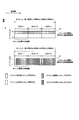
- FIG. 2 is a diagram illustrating an example of the frequency band aggregation processing according to the present embodiment.
- the horizontal axis represents the frequency domain
- the vertical axis represents the time domain.
- the downlink subframe D1 is configured by subframes of three carrier elements (DCC-1: Downlink Component Carrier-1, DCC-2, and DCC-3) having a bandwidth of 20 MHz.
- DCC-1 Downlink Component Carrier-1, DCC-2, and DCC-3
- a downlink control channel indicated by a hatched area by a grid line and a downlink shared channel indicated by an area not hatched are time-multiplexed. Assigned.
- the uplink subframe U1 is composed of three carrier elements (UCC-1: Uplink Component Carrier-1, UCC-2, UCC-3) having a bandwidth of 20 MHz.
- an uplink control channel indicated by a hatched area with diagonal grid lines, and an uplink shared channel indicated by a hatched area on the left diagonal line Are frequency-multiplexed and assigned.
- the base station apparatus b1 arranges a signal in a downlink shared channel of one or a plurality of downlink carrier elements among three downlink carrier elements in a certain downlink subframe, and transmits the signal to the mobile station apparatus a1.
- the mobile station apparatus a1 arranges a signal in an uplink shared channel of one or a plurality of uplink carrier elements among three uplink carrier elements in a certain uplink subframe, and transmits the signal to the base station apparatus b1. .
- FIG. 3 is a schematic diagram illustrating an example of a configuration of a downlink radio frame according to the present embodiment.
- FIG. 3 shows a configuration of a radio frame in a certain downlink carrier element.
- the horizontal axis represents the time domain
- the vertical axis represents the frequency domain.
- the radio frame of the downlink carrier element is composed of a plurality of downlink physical resource block (PRB) pairs (for example, an area surrounded by a broken line in FIG. 3).
- PRB downlink physical resource block
- One downlink physical resource block pair is composed of two downlink physical resource blocks (PRB bandwidth ⁇ slot) that are continuous in the time domain.
- One downlink physical resource block (unit surrounded by a thick line in FIG. 3) is composed of 12 subcarriers in the frequency domain, and is composed of 7 OFDM symbols in the time domain.
- a slot composed of 7 OFDM symbols, a subframe composed of 2 slots, and a radio frame composed of 10 subframes.
- a plurality of downlink physical resource blocks (PRBs) are arranged according to the bandwidth of the downlink carrier element.
- a unit including one subcarrier and one OFDM symbol is referred to as a downlink resource element (RE).
- RE downlink resource element
- a channel allocated in a downlink radio frame will be described.
- a downlink control channel for example, a downlink control channel, a downlink shared channel, and a downlink reference signal are allocated.
- the downlink control channel is arranged from the first OFDM symbol of the subframe, and the downlink shared channel is arranged in the remaining OFDM symbols of the subframe.
- the downlink pilot channel is not shown in FIG. 3 for the sake of simplicity of explanation, but the downlink pilot channel is distributed in the frequency domain and the time domain.
- the downlink control channel includes a communication including an information format such as a downlink grant, an uplink grant, and a transmission power control format (information format of a control channel for transmission power control).
- a downlink control information (DCI) signal which is information used for the control of, is arranged.
- the downlink grant is information indicating a modulation scheme for the downlink shared channel, information indicating a coding scheme, information indicating radio resource allocation, information on HARQ (Hybrid Automatic Repeat Request), and information about a downlink automatic repeat request.
- Consists of TPC command Transmission Power Control command
- the uplink grant is information indicating a modulation scheme for the uplink shared channel, information indicating a coding scheme, information indicating radio resource allocation, HARQ information, and uplink shared where the uplink grant indicates radio resource allocation.
- a channel and a TPC command for the sounding reference signal of the same uplink carrier element as the uplink shared channel are configured.
- HARQ means that, for example, the mobile station device a1 (base station device b1) transmits success or failure (ACK / NACK) of decoding of data information to the base station device b1 (mobile station device a1), and the mobile station device a1 ( When the base station apparatus b1) cannot decode the data information due to an error (NACK), the base station apparatus b1 (mobile station apparatus a1) retransmits the signal and the mobile station apparatus a1 (base station apparatus b1) receives the signal again.
- This is a technique for performing a decoding process on a composite signal with a signal that has already been received.
- the transmission power control format is composed of an uplink shared channel of each uplink carrier element of the plurality of mobile station apparatuses a1 or a TPC command for the uplink control channel.
- the number of bits of one TPC command included in the transmission power control format is the same, and the transmission power control format does not include the TPC commands for the uplink shared channel and the uplink control channel at the same time.
- the base station apparatus b1 selects the number of bits of one TPC command included in the transmission power control format, and notifies the mobile station apparatus a1 of the selected number of bits.
- the TPC command received in the downlink grant, uplink grant, and transmission power control format is applied after a predetermined time. In this embodiment, every time a TPC command is received, only the received TPC command is applied to transmission power control. However, a value obtained by accumulating the values of TPC commands received so far may be applied. .
- a sequence obtained by performing an exclusive OR with a cyclic redundancy check (CRC) code generated from the bit sequence of the downlink control information and the identifier is added. Furthermore, the mobile station apparatus a1 can obtain a cyclic redundancy check code by performing an exclusive OR with the identifier assigned to this sequence. That is, the mobile station apparatus a1 can determine from the identifier included in the downlink control channel whether the downlink control channel is transmitted to the own apparatus.
- CRC cyclic redundancy check
- the downlink grant and uplink grant transmitted to a specific mobile station device a1 include a C-RNTI (Cell-Radio Network Temporary Identifier), which is an identifier assigned to the mobile station device a1 by the base station device b1.
- C-RNTI Cell-Radio Network Temporary Identifier
- the TPC-PUCCH-RNTI Transmission Power Control-Physical Channel-Radio Network-Purdio-Tempor-CTP
- the base station apparatus b1 assigns to a plurality of mobile station apparatuses a1.
- TPC-RNTI Transmission Power Control-Physical Uplink Shared Channel-Radio Network Temporary Identifier
- TPC-PUCCHNT-RUCPC Transmission Power Control format-TPC-PUCCHNT-RUCPC
- TPC command included in the transmission power control format is for a physical uplink control channel, whether it is or not for the uplink shared channel and the sounding reference signal.
- a signal arranged in the downlink shared channel will be described.
- a data information (transport block) signal (referred to as a data signal) is arranged.
- the radio resources of the downlink shared channel are allocated using the downlink grant, and are arranged in the same downlink subframe as the downlink control channel including the downlink grant.
- the downlink shared channel indicated by the radio resource allocation by the downlink control channel and the downlink control channel is arranged in the same downlink carrier element.
- the present invention is not limited to this, and the downlink carrier element in which the downlink shared channel is arranged is identified from the downlink grant, and the downlink control channel and the downlink control channel indicate the assignment of radio resources.
- the shared channel may be arranged in different downlink carrier elements.
- the downlink control channel is arranged in one or more control channel elements (CCE).
- CCE control channel elements
- the control channel element is composed of a plurality of resource element groups (REG, also referred to as mini-CCE) distributed in the frequency time domain within the downlink carrier element.
- the resource element group is composed of four downlink resource elements that are continuous in the frequency domain except for the downlink reference signal within the same OFDM symbol of the same downlink carrier element.
- the downlink control channel is arranged in one, two, four, or eight control channel elements having consecutive numbers for identifying control channel elements.
- a common search space composed of predetermined control channel elements (Common Search Space) and a mobile station apparatus specific search space composed of the same or different control channel elements for each mobile station apparatus a1 (User Equipment- a specific search space) is configured for each downlink carrier element.
- the common search space and the mobile station apparatus specific search space are configured as different common search spaces and mobile station apparatus specific search spaces for each number of control channel elements in which the downlink control channel is arranged. That is, when the downlink control channel is arranged in one, two, four, or eight control channel elements, four mobile station apparatus specific search spaces are configured.
- different common search spaces and mobile station apparatus specific search spaces may be configured using the same control channel element.
- the common search space includes information such as a downlink control channel including information addressed to a plurality of mobile station apparatuses a1, such as a transmission power control format, and a downlink grant and uplink grant addressed to a specific mobile station apparatus a1.
- a downlink control channel is arranged.
- a downlink control channel including information such as a downlink grant and an uplink grant addressed to the mobile station apparatus a1 monitoring the mobile station apparatus specific search space is arranged.
- the base station apparatus b1 sets the downlink carrier element which monitors a downlink control channel in a common search space for every mobile station apparatus a1, and notifies the set downlink carrier element to the mobile station apparatus a1.
- the downlink carrier element that monitors the common search space set for each mobile station apparatus a1 is referred to as an anchor downlink carrier element.
- FIG. 4 is a schematic diagram illustrating an example of a configuration of an uplink radio frame according to the present embodiment.
- FIG. 4 shows the configuration of a radio frame in a certain uplink carrier element.
- the horizontal axis is the time domain
- the vertical axis is the frequency domain.
- the radio frame of the uplink carrier element is composed of a plurality of uplink physical resource block (PRB) pairs (for example, an area surrounded by a broken line in FIG. 4).
- PRB physical resource block
- One uplink physical resource block pair is composed of two uplink physical resource blocks (PRB bandwidth ⁇ slot) that are continuous in the time domain.
- One uplink physical resource block (unit surrounded by a thick line in FIG. 4) is composed of 12 subcarriers in the frequency domain, and is composed of 7 SC-FDMA symbols in the time domain. .
- uplink resource elements In the time domain, there are slots composed of 7 SC-FDMA symbols, subframes composed of 2 slots, and radio frames composed of 10 subframes.
- PRBs uplink physical resource blocks
- a unit composed of one subcarrier and one SC-FDMA symbol is referred to as an uplink resource element (RE).
- an uplink control channel for example, an uplink control channel, an uplink shared channel, and an uplink reference signal are allocated.
- the uplink control channel is allocated to uplink physical resource block pairs (regions hatched with left diagonal lines) at both ends of the bandwidth of the uplink carrier element. Note that the uplink control channel is spread by spreading codes in the frequency domain and the time domain, and is code-multiplexed.
- the uplink shared channel is allocated to uplink physical resource block pairs (regions not hatched) other than the uplink control channel.
- the mobile station apparatus a1 does not place a signal on both the uplink control channel and the uplink shared channel in a certain uplink subframe.
- a demodulation reference signal (not shown) is time-multiplexed and assigned to the uplink shared channel and the uplink control channel.
- the sounding reference signal is arranged in the last SC-FDMA symbol of a subframe having a period set by the base station apparatus b1 for each mobile station apparatus a1 in the time domain.
- the base station apparatus b1 is arranged in the frequency domain set for each mobile station apparatus a1.
- Uplink control information (UCI) signals which are information used for communication control, such as channel quality information, scheduling request (SR), ACK / NACK, and the like are arranged in the uplink control channel.
- the channel quality information is information indicating the transmission quality of the downlink channel measured by the mobile station apparatus a1 using the downlink reference signal.
- the scheduling request is information transmitted when the mobile station apparatus a1 requests the base station apparatus b1 to allocate uplink radio resources.
- ACK / NACK is information indicating success or failure of decoding of the downlink shared channel received by the mobile station apparatus a1.
- the radio resource of the uplink control channel for transmitting the channel quality information and the scheduling request is periodically allocated by the base station apparatus b1 for each mobile station apparatus a1.
- the radio resource of the uplink control channel for transmitting ACK / NACK corresponds to the control channel element in which the downlink grant indicating the allocation of the radio resource of the downlink shared channel corresponding to ACK / NACK is arranged in the frequency domain. It is a radio resource of the uplink control channel, and a radio resource after a predetermined time after receiving the downlink shared channel in the time domain is used.
- ACK / NACK radio resources of the same uplink carrier element are associated with radio resources of the downlink control channel of the same downlink carrier element.
- the TPC command for the uplink control channel included in the downlink grant is for an uplink carrier element in which the ACK / NACK radio resource corresponding to the downlink grant is arranged.
- a signal (referred to as a data signal) of data information (transport block) that is information other than uplink control information is arranged in the uplink shared channel.
- the radio resource of the uplink shared channel is allocated using the uplink grant, and is arranged in a subframe after a predetermined time from the subframe that has received the uplink grant.
- the mobile station apparatus a1 determines the uplink carrier element in which the uplink shared channel in which the uplink grant indicates radio resource allocation is arranged from the downlink carrier element that has received the uplink grant.
- the TPC command for the uplink shared channel and the sounding reference signal included in the uplink grant is for the uplink carrier element in which the uplink shared channel corresponding to the uplink ground is arranged.
- the present invention is not limited to this, and the uplink carrier element in which the uplink shared channel is arranged may be identified from the uplink grant.
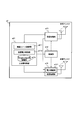
- FIG. 5 is a schematic block diagram showing the configuration of the base station apparatus b1 according to this embodiment.
- the base station device b1 includes an upper layer processing unit b11, a control unit b12, a reception processing unit b13, a plurality of reception antennas, a transmission processing unit b14, and a plurality of transmission antennas.
- the upper layer processing unit b11 includes a radio resource control unit b111, a transmission power control unit b112, and a storage unit b113.
- the receiving antenna and the transmitting antenna are configured differently, but the antenna may be shared by using a thyristor or the like that switches the input / output of a signal.
- the upper layer processing unit b11 outputs data information and the like for each downlink carrier element acquired from the upper node to the transmission processing unit b14.
- the upper layer processing unit b11 performs processing of a packet data integration protocol (PDCP: Packet Data Convergence Protocol) layer, a radio link control (RLC: Radio Link Control) layer, and a radio resource control (RRC: Radio Resource Control) layer.
- PDCP Packet Data Convergence Protocol
- RLC Radio Link Control
- RRC Radio Resource Control
- the radio resource control unit b111 of the upper layer processing unit b11 performs management of various setting information, communication status, buffer status, and the like of each mobile station apparatus a1.
- the transmission power control unit b112 of the higher layer processing unit b11 manages the uplink transmission power of each mobile station apparatus a1.
- the storage unit b113 of the upper layer processing unit b11 stores various setting information of the mobile station device a1 set by the radio resource control unit b111 and the transmission power control
- the radio resource control unit b111 included in the upper layer processing unit b11 transmits the number of downlink carrier elements and uplink carrier elements that the base station apparatus b1 can use for radio communication, and the mobile station apparatus a1 transmits simultaneously, Alternatively, a plurality of uplink carrier elements and downlink carrier elements are allocated to the mobile station apparatus a1 according to the number of downlink carrier elements and uplink carrier elements that can be received.
- the radio resource control unit b111 based on the channel quality information indicating the number of mobile station devices a1 accommodated in the downlink carrier element and the quality of the propagation path of the downlink carrier element received from the mobile station device a1, An anchor downlink carrier element that transmits a transmission power control format addressed to the device a1 is allocated to the mobile station device a1. Also, the radio resource control unit b111 sends the mobile station apparatus a1 C-RNTI for identifying the mobile station apparatus a1 and downlink control information, TPC-PUCCH-RNTI for identifying the transmission power control format, and TPC. -Assign and notify PUSCH-RNTI and TPC command number (field).
- the radio resource control unit b111 selects a plurality of downlink carrier elements and uplink carrier elements, and sets the selected downlink carrier elements and radio resources in the uplink carrier elements to the mobile station apparatus a1 as radio resources for arranging data information. assign.
- the radio resource control unit b111 transmits the downlink grant and the uplink grant indicating the allocation as downlink control information to the mobile station apparatus a1 via the transmission processing unit b14.
- the downlink grant and the uplink grant are added with a sequence obtained by performing an exclusive OR of the C-RNTI and the cyclic redundancy check code assigned to the mobile station apparatus a1 corresponding to the downlink grant or the uplink grant. .
- the radio resource control unit b111 manages various setting information, communication status, buffer status, and the like of each mobile station apparatus a1. Further, the radio resource control unit b111 generates information acquired in each channel of each downlink carrier element or acquires it from a higher-order node, and outputs the information to the transmission processing unit b14 for each downlink carrier element. For example, the radio resource control unit b111 generates downlink control information and outputs it to the transmission processing unit b14.
- the radio resource control unit b111 transmits uplink control information (ACK / NACK, channel quality information, scheduling request, and buffer status of the mobile station apparatus a1) notified from the mobile station apparatus a1 through the uplink control channel, and radio. Based on the various setting information of each mobile station apparatus a1 set by the resource control unit b111, control information is generated to control the reception processing unit and the transmission processing unit, and is output to the control unit b12. For example, when the transmission processing unit arranges the transmission power control format, the radio resource control unit b111 performs common search for the anchor downlink carrier element allocated to the mobile station device a1 corresponding to the TPC command included in the transmission power control format. The control information is output to the control unit b12 so that the transmission power control format is arranged in the space.
- uplink control information ACK / NACK, channel quality information, scheduling request, and buffer status of the mobile station apparatus a1 notified from the mobile station apparatus a1 through the uplink control channel, and radio.
- control information is generated to control the
- the transmission power control unit b112 included in the higher layer processing unit b11 is based on information notified from the other base station device b1, the received power of the uplink channel received from the mobile station device a1, and the like.
- the transmission power of the uplink channel is determined for each uplink carrier element of each mobile station apparatus a1.
- the information notified from the other base station apparatus b1 includes the amount of interference given to the other base station apparatus b1 given by the mobile station apparatus a1 communicating with the own apparatus, and the movement communicating with the other base station apparatus b1. This is information about the amount of interference that the station device a1 will give to the device itself.
- the transmission power control unit determines the transmission power of the uplink channel for each uplink carrier element of each mobile station apparatus 1a
- the transmission power control unit determines the value of the TPC command for controlling the transmission power for each uplink carrier element. Generate information for.
- the transmission power control unit b112 generates a transmission power control format by allocating the TPC commands for the mobile station apparatus a1 to which the same anchor downlink carrier element is assigned and the same TPC-PUCCH-RNTI or TPC-PUSCH-RNTI is assigned. And it transmits to the mobile station apparatus a1 via the transmission process part b14.
- the transmission power control unit b112 includes a TPC command for an uplink carrier element corresponding to the uplink grant or the downlink grant, via the transmission processing unit b14, Transmit to the mobile station device a1.
- exclusive OR of TPC-PUCCH-RNTI or TPC-PUSCH-RNTI and cyclic redundancy check code assigned to a plurality of mobile station apparatuses a1 corresponding to the transmission power control format is performed. A series is added. If the TPC command included in the transmission power control format is for the uplink control channel, TPC-PUCCH-RNTI is used. If the TPC command is for the uplink shared channel, TPC-PUSCH-RNTI is Used.
- the storage unit b113 of the higher layer processing unit b11 stores various setting information of the mobile station device a1 set by the radio resource control unit b111 and the transmission power control unit b112.
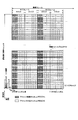
- FIG. 6 is a diagram illustrating an example of various setting information stored in the storage unit b113 according to the present embodiment.
- setting information for each of the N mobile station apparatuses a1 (A1, A2,..., AN) is stored, and the radio resource control unit b111 and the transmission power control unit b112 of the higher layer processing unit b11 are stored.
- the anchor downlink carrier element number, the TPC-PUCCH-RNTI and TPC-PUSCH-RNTI identifiers (hexadecimal), and the TPC-PUCCH-RNTI and TPC-PUSCH-RNTI are stored in the form of a table. is doing. Note that the TPC command number and transmission power for the uplink carrier element not assigned to the mobile station apparatus a1 are left blank.
- the base station apparatus b1 transmits the same TPC-PUSCH-RNTI and TPC to the mobile station apparatus a1 to which the same anchor downlink carrier element is allocated, as in the mobile station apparatus A1 and the mobile station apparatus AN in FIG. Assign PUCCH-RNTI.
- the base station apparatus b1 only has to transmit a transmission power control format including one TPC-PUCCH-RNTI and TPC-PUSCH-RNTI using one downlink carrier element.
- the base station apparatus b1 allocates the same anchor downlink carrier element when the number of mobile station apparatuses a1 to which the same anchor downlink carrier element is allocated is larger than the number of TPC commands that can be transmitted in the transmission power control format.
- the mobile station device a1 is divided into a plurality of groups, and the same TPC-PUCCH-RNTI and TPC-PUSCH-RNTI are assigned to each of the mobile station devices a1 in the same group.
- TPC-PUCCH-RNTI and TPC-PUSCH-RNTI assigned to the mobile station apparatus a1 to which different anchor downlink carrier elements are assigned may be the same or different.
- the base station apparatus b1 assigns the same TPC-PUCCH-RNTI or TPC-PUSCH-RNTI to the mobile station apparatus a1 to which different anchor downlink carrier elements are assigned, so that the TPC-PUCCH-RNTI is assigned to each downlink carrier element.
- TPC-PUSCH-RNTI can be reused, and identifier resources (information resources that can be expressed by the number of bits used for identifiers) can be reduced.
- the TPC-PUCCH-RNTI and TPC-PUSCH-RNTI assigned to the mobile station device a1 to which the different anchor downlink carrier elements are assigned by the base station device b1 different, one TPC-PUCCH-RNTI and TPC Only one group of mobile station apparatuses corresponds to -PUSCH-RNTI, management of the identifier of the base station apparatus b1 is simplified, and the structure of the base station apparatus b1 can be simplified.
- the same TPC command number is assigned regardless of the number of bits of one TPC command included in the transmission power control format, but one TPC command included in the transmission power control format is assigned.
- a different TPC command number may be assigned for each bit number.
- the control unit b12 generates a control signal for controlling the reception processing unit b13 and the transmission processing unit b14 based on the control information from the higher layer processing unit b11.
- the control unit b12 outputs the generated control signal to the reception processing unit b13 and the transmission processing unit b14 to control the reception processing unit b13 and the transmission processing unit b14.
- the reception processing unit b13 demodulates and decodes the reception signal received from the mobile station device a1 via the reception antenna according to the control signal input from the control unit b12, and outputs the decoded information to the upper layer processing unit b11. Specifically, the reception processing unit b13 converts the signal of each uplink carrier element received via each reception antenna into an intermediate frequency (down-conversion), removes unnecessary frequency components, and appropriately sets the signal level. The amplification level is controlled so as to be maintained, and based on the in-phase component and the quadrature component of the received signal, quadrature demodulation is performed, and the quadrature demodulated analog signal is converted into a digital signal.
- the receiving unit removes a portion corresponding to a guard interval (GI) from the converted digital signal.
- the receiving unit performs a fast Fourier transform (FFT) on the signal from which the guard interval is removed, and extracts a frequency domain signal.
- FFT fast Fourier transform
- the reception processing unit b13 separates the extracted signal into signals arranged in the uplink control channel, the uplink shared channel, the demodulation reference signal, and the sounding reference signal for each uplink carrier element. Also, since the uplink control channel is code-multiplexed, it is despread and separated. This separation is performed based on radio resource allocation information that is determined in advance by the base station apparatus b1 and notified to each mobile station apparatus a1. Further, an estimated value of the propagation path is obtained from the separated uplink reference signal, and the propagation paths of the uplink control channel and the uplink shared channel are compensated.
- the reception processing unit b13 performs an inverse discrete Fourier transform (IDFT) on the uplink shared channel, obtains a modulation symbol, and applies a bi-phase bias to each of the modulation symbol of the uplink control channel and the uplink shared channel.
- IFT inverse discrete Fourier transform
- Shift modulation (Binary Phase Shift Keying; BPSK), four-phase phase shift keying (Quadrature Phase Shift Keying; QPSK), 16-value quadrature amplitude modulation (16 Quadrature Amplitude Modulation; 64QAM Modulation value; ) Etc.
- the base station device b1 is a mobile station It demodulates the received signal using the modulation scheme reported in advance by the uplink grant to the location a1 respectively.
- the reception processing unit b13 transmits the demodulated encoded bits of the uplink control channel and the uplink shared channel to the mobile station device a1 by using a predetermined encoding method, or the base station device b1 transmits to each mobile station device a1. Decoding is performed at a coding rate notified in advance by the link grant, and data information and uplink control information are output to the upper layer processing unit b11.
- the reception processing unit b13 measures the reception power of the uplink reference signal received from each mobile station apparatus a1 and the reception signal of the uplink shared channel, measures the transmission quality of the channel of the uplink carrier element, and the upper layer processing unit output to b11.
- the transmission processing unit b14 generates a downlink reference signal according to the control signal input from the control unit b12, encodes and modulates the data information and the downlink control information input from the higher layer processing unit b11, and transmits the downlink reference signal. It arrange
- Encoding such as convolutional encoding and block encoding is performed, and the encoded bits are modulated by a modulation scheme such as QPSK, 16QAM, or 64QAM. Further, the mobile station device a1 generates a known sequence as a downlink reference signal, which is obtained by a predetermined rule based on a cell identifier for identifying the base station device b1, and is shared by the downlink control channel and the downlink. Multiplex channel and downlink reference signals.
- the transmission power control format is multiplexed in the common search space of the anchor downlink carrier element assigned to the mobile station apparatus a1 to which the TPC command included in the transmission power control format corresponds, and the downlink grant and the uplink grant are In the common search space of the anchor downlink carrier element allocated to the mobile station apparatus a1 corresponding to the downlink grant and the uplink grant, or the mobile station apparatus specific search space for each downlink carrier element allocated to the mobile station apparatus a1 Is multiplexed.
- the transmission processing unit b14 performs an inverse fast Fourier transform (IFFT) on the multiplexed modulation symbol, modulates the OFDM scheme, adds a guard interval to the OFDM symbol modulated by OFDM, and performs baseband digital Generate a signal, convert the baseband digital signal to an analog signal, generate in-phase and quadrature components of the intermediate frequency from the analog signal, remove excess frequency components for the intermediate frequency band, and increase the signal of the intermediate frequency
- the signal is converted (up-converted) into a frequency signal, an extra frequency component is removed, the power is amplified, and the signal is output to the transmitting antenna and transmitted.
- IFFT inverse fast Fourier transform
- FIG. 7 is a schematic block diagram showing the configuration of the mobile station apparatus a1 according to this embodiment.
- the mobile station device a1 includes an upper layer processing unit a11, a control unit a12, a reception processing unit a13, a plurality of reception antennas, a transmission processing unit a14, and a plurality of transmission antennas.
- the upper layer processing unit a11 includes a radio resource control unit a111, a transmission power control unit a112, and a storage unit a113.
- the transmission processing unit a14 includes a power amplification unit a141.
- the receiving antenna and the transmitting antenna are configured differently, but the antenna may be shared by using a thyristor or the like that has an effect of switching signal input / output.
- the upper layer processing unit a11 outputs data information for each uplink carrier element generated by a user operation or the like to the transmission processing unit a14.
- the upper layer processing unit a11 performs processing of the packet data integration protocol layer, the radio link control layer, and the radio resource control layer.
- the radio resource control unit a111 provided in the upper layer processing unit a11 manages various setting information, communication status, buffer status, and the like of the own device.
- the transmission power control unit a112 of the higher layer processing unit a11 manages uplink transmission power of the own apparatus.
- the storage unit a113 of the upper layer processing unit a11 stores various setting information of the own device managed by the radio resource control unit a111.
- the radio resource control unit a111 included in the higher layer processing unit a11 includes the downlink carrier element, uplink carrier element, anchor downlink carrier element, C-RNTI, TPC-PUCCH-RNTI, and TPC- to which the own apparatus is allocated. It manages various setting information such as PUSCH-RNTI. Also, the radio resource control unit a111 generates information to be arranged in each channel of each uplink carrier element, and outputs the information to the transmission processing unit a14 for each uplink carrier element. For example, the radio resource control unit a111 generates ACK / NACK for the data information of the downlink shared channel according to the result of the HARQ process, and outputs the generated ACK / NACK to the transmission processing unit a14.
- the radio resource control unit a111 transmits downlink control information (for example, downlink grant, uplink grant) notified from the base station apparatus b1 through the downlink control channel, and various settings of the own apparatus managed by the radio resource control unit a111. Based on the information, control information is generated to control the reception processing unit a13 and the transmission processing unit a14, and is output to the control unit a12. For example, when the reception processing unit a13 monitors the downlink control channel, the radio resource control unit a111 monitors the transmission power control format in the common search space of the anchor downlink carrier element, and the downlink grant and the uplink addressed to the own device. Control information is output to the control unit a12 so that the link grant is monitored in the common search space of the anchor downlink carrier element and the mobile station apparatus specific search space of each downlink carrier element.
- downlink control information for example, downlink grant, uplink grant
- the transmission power control unit a113 provided in the upper layer processing unit a11 determines the uplink channel from the TPC command notified from the base station device b1 or the path loss measured by the mobile station device a1 from the downlink reference signal. Control of transmission power is performed, and control information is generated to control the power amplifier a141, and is output to the controller a12.
- the storage unit a113 of the upper layer processing unit a11 stores various setting information of the own device managed by the radio resource control unit a111 and the transmission power control unit a112.
- FIG. 8 is a diagram illustrating an example of various setting information stored in the storage unit a113 according to the present embodiment. In FIG.
- the own apparatus sets the anchor downlink carrier element number set in the base station apparatus b1, the TPC-PUCCH-RNTI and TPC-PUSCH-RNTI identifiers (hexadecimal), the TPC-PUCCH-RNTI, and the TPC- For each PUSCH-RNTI, the TPC command number included in the transmission power control format supported by the uplink carrier element of the own device and the value of the transmission power currently designated by the TPC command are stored in the form of a table. is doing.
- the uplink carrier element corresponding to the downlink grant TPC command is the downlink grant element.
- An uplink carrier element to which the TPC command is applied and the downlink grant TPC command does not support the format 3 / 3A TPC command.
- the uplink carrier element corresponding to the uplink grant TPC command is the uplink grant element.
- the TPC command of the format 3 / 3A is applied to the uplink carrier element to which the TPC command is applied and the uplink grant TPC command is not supported.
- FIG. 9 is a diagram illustrating an example of a configuration of a transmission power control format according to the present embodiment.
- the transmission power control format includes M TPC commands (squares marked with TPC #i; i is an integer), and the hatched squares are generated from M TPC commands. This is a sequence obtained by performing an exclusive OR of the cyclic redundancy check code and TPC-PUCCH-RNTI (or TPC-PUSCH-RNTI).
- the mobile station apparatus a1 having the setting information as shown in FIG. 8 is a TPC-PUCCH-RNTI assigned to the own apparatus in the common search space of the downlink carrier element of DCC-2 that is the anchor downlink carrier element.
- the second TPC command of the detected transmission power control format is the TPC command for the uplink carrier element of UCC-1
- the third TPC command is the UCC.
- the fourth TPC command is determined as a TPC command for the UCC-3 uplink carrier element, and the value of the transmission power indicated by the TPC command in the storage unit a113 of the higher layer processing unit a11 is set. Update.
- the control unit a12 generates a control signal for controlling the reception processing unit a13 and the transmission processing unit a14 based on the control information from the upper layer processing unit a11.
- the control unit a12 outputs the generated control signal to the reception processing unit a13 and the transmission processing unit a14 to control the reception processing unit a13 and the transmission processing unit a14.
- the reception processing unit a13 demodulates and decodes the reception signal received from the base station apparatus b1 via the reception antenna according to the control signal input from the control unit a12, and outputs the decoded information to the higher layer processing unit a11. . Also, the reception processing unit a13 generates channel quality information based on the detected reception quality of the downlink reference signal and outputs the channel quality information to the transmission processing unit a14.
- the reception processing unit a13 converts each uplink carrier element signal received via each reception antenna into an intermediate frequency (down-conversion), removes unnecessary frequency components, and appropriately sets the signal level.
- the amplification level is controlled so as to be maintained, and based on the in-phase component and the quadrature component of the received signal, quadrature demodulation is performed, and the quadrature demodulated analog signal is converted into a digital signal.
- the receiving unit a13 removes a portion corresponding to the guard interval from the converted digital signal.
- the receiving unit a13 performs fast Fourier transform on the signal from which the guard interval is removed, and extracts a frequency domain signal.
- the reception processing unit a13 separates the extracted signal into signals arranged in the downlink control channel, the downlink shared channel, and the downlink reference signal for each downlink carrier element. This separation is performed based on radio resource allocation information notified by the downlink grant. Also, the reception processing unit a13 obtains an estimated value of the propagation path from the separated downlink reference signal, and compensates the propagation path of the downlink control channel and the downlink shared channel. Also, the reception processing unit a13 generates channel quality information based on the reception quality of the separated downlink reference signal and outputs the channel quality information to the transmission processing unit a14.
- the reception processing unit a13 demodulates the QPSK modulation scheme for the downlink control channel, and the transmission power control format is set as the common search space of the anchor downlink carrier element in the common search space of the anchor downlink carrier element.
- the downlink grant and the uplink grant are monitored in the mobile station device specific search space of each downlink carrier element, and decoding is attempted.
- the decoded downlink control information is output to the higher layer processing unit a11.
- the reception processing unit a13 performs demodulation of the modulation scheme notified by the downlink grant such as QPSK, 16QAM, and 64QAM on the downlink shared channel, performs decoding on the coding rate notified by the downlink grant,
- the data information is output to the upper layer processing unit a11.
- the transmission processing unit a14 generates an uplink reference signal according to the control signal input from the control unit a12, the data information input from the higher layer processing unit a11, ACK / NACK, and input from the reception processing unit a13
- the channel quality information is encoded and modulated, arranged in the uplink shared channel and the uplink control channel, multiplexed with the generated uplink reference signal, and transmitted to the base station apparatus b1 via the transmission antenna.
- the transmission processing unit a14 transmits the uplink control information and data information of each uplink carrier element input from the higher layer processing unit a11 and the reception processing unit a13 according to the control signal input from the control unit a12. Then, encoding such as turbo encoding, convolutional encoding, and block encoding is performed, and the encoded bits are modulated by a modulation scheme such as BPSK, QPSK, 16QAM, and 64QAM.
- a modulation scheme such as BPSK, QPSK, 16QAM, and 64QAM.
- the transmission processing unit a14 generates, as an uplink reference signal, a sequence known by the base station device b1, which is obtained according to a predetermined rule based on a cell identifier for identifying the base station device b1.
- the transmission processing unit a14 spreads the modulation symbol of the uplink control channel with a code, rearranges the modulation symbol of the uplink shared channel in parallel, and then performs discrete Fourier transform (DFT), and the generated uplink reference Multiplex with signal.
- DFT discrete Fourier transform
- the transmission processing unit a14 performs inverse fast Fourier transform on the multiplexed signal, performs SC-FDMA modulation, adds a guard interval to the SC-FDMA modulated SC-FDMA symbol, and generates a baseband digital signal
- the baseband digital signal is converted into an analog signal, the in-phase and quadrature components of the intermediate frequency are generated from the analog signal, the extra frequency components for the intermediate frequency band are removed, and the intermediate frequency signal is converted to the high frequency signal Is converted (up-converted) to remove excess frequency components, power-amplified, and output to a transmission antenna for transmission.
- the power amplifying unit a141 amplifies the transmission power of the uplink control channel, the uplink shared channel, and the sounding reference signal according to the control signal input from the control unit a12. Note that the transmission power of the demodulation reference signal is amplified to the same value as the transmission power of the channel on which the demodulation reference signal is time-multiplexed.
- FIG. 10 is a diagram showing a method of applying a TPC command to the uplink shared channel of the mobile station apparatus a1 according to this embodiment.
- the mobile station apparatus a1 has downlink carrier elements (DCC-1, DCC-2, DCC-3) and uplink carrier elements (UCC-1, UCC-2, UCC-3) as shown in FIG. A case where DCC-2 is set as an anchor downlink carrier element is shown.
- DCC-1, DCC-2, DCC-3 downlink carrier elements
- UCC-1, UCC-2, UCC-3 uplink carrier elements
- the horizontal axis indicates the time domain
- the square with a line on the diagonal grid indicates the transmission power control format including the TPC-PUSCH-RNTI allocated to the mobile station apparatus a1
- the vertical and horizontal Squares with grid lines indicate uplink grants
- hatched squares indicate uplink shared channels
- dotted squares indicate sounding reference signals
- thick arrows indicate transmit power control Format, an uplink carrier element corresponding to an uplink shared channel included in the uplink grant and a TPC command corresponding to the sounding reference signal, and a time when the TPC command is applied.
- the TPC command included in the uplink grant received by DCC-1 is for UCC-1
- the TPC command included in the uplink grant received by DCC-2 is for the uplink grant for UCC-2
- the TPC command included in the uplink grant received by DCC-3 is for UCC-3
- the transmission power control format received in the common search space of DCC-2 includes UCC-1 and UCC. -2 and TCC commands for UCC-3 are included.
- the TPC command in the transmission power control format received in the search space is for each uplink carrier element after four subframes after the transmission power control format is received.
- the mobile station apparatus a1 transmits the TPC command of the uplink grant for the same uplink carrier element and the TPC command of the format for transmission power control.
- the uplink grant TPC command is preferentially applied.
- the base station apparatus a1 detects whether the uplink shared channel corresponding to the uplink grant is transmitted from the mobile station apparatus a1, so that the mobile station apparatus a1 correctly receives the uplink grant and applies the TPC command. Therefore, it is possible to control transmission power more accurately by preferentially selecting an uplink grant TPC command.
- FIG. 11 is a flowchart showing an example of the operation of the base station apparatus b1 according to the present embodiment.
- the base station apparatus b1 uses the number of downlink carrier elements and uplink carrier elements that the base station apparatus b1 can use for wireless communication, and the downlink carrier elements that the mobile station apparatus a1 can transmit or receive simultaneously. Depending on the number of uplink carrier elements and the like, a plurality of uplink carrier elements and downlink carrier elements are allocated to the mobile station apparatus a1.
- the process proceeds to step S101.
- Step S101 The base station apparatus b1 performs this movement based on the channel quality information indicating the number of mobile station apparatuses a1 accommodated in the downlink carrier element and the quality of the propagation path of the downlink carrier element received from the mobile station apparatus a1.
- An anchor downlink carrier element that transmits a transmission power control format addressed to the station apparatus is allocated to the mobile station apparatus a1.
- the process proceeds to step S102.
- the base station apparatus b1 uses the transmission power control format and identifiers (TPC-PUCCH-RNTI, TPC-PUSCH-RNTI) for identifying the channel corresponding to the TPC command included in the transmission power control format. Then, a number for identifying a plurality of TPC commands for the uplink carrier element allocated to the mobile station apparatus a1 included in the transmission power control format is allocated to the mobile station apparatus a1.
- the base station apparatus b1 divides the mobile station apparatus a1 to which the same anchor downlink carrier element is allocated into a plurality of groups, and allocates the same TPC-PUCCH-RNTI and TPC-PUSCH-RNTI to each mobile station apparatus a1 in the same group. .
- Step S103 The base station apparatus b1 receives the amount of interference from the other base station apparatus b1 to the other base station apparatus b1 given by the mobile station apparatus a1 communicating with the base station apparatus b1, or the mobile station apparatus a1.
- the transmission power of the channel of the mobile station apparatus a1 is determined based on the received power of the uplink channel received from the mobile station apparatus a1.
- step S104 the process proceeds to step S104.
- Step S104 The base station apparatus b1 generates a TPC command to notify the mobile station apparatus a1 so that the transmission power of each uplink channel becomes the transmission power determined in step S103.
- step S105 The base station apparatus b1 generates a transmission power control format from the TPC command for each mobile station apparatus a1 to which the same identifier is assigned among the plurality of TPC commands generated in step S104.
- a TPC command is included in the uplink grant or the downlink grant.
- step S106 the process proceeds to step S106.
- Step S106 The base station apparatus b1 encodes and modulates downlink control information (transmission power control format, downlink grant, and uplink grant), and transmits it on the downlink control channel.
- the transmission power control format is arranged in the common search space of the anchor downlink carrier element assigned to each mobile station apparatus a1 in step S101, and the downlink grant and the uplink grant are the common search space of the anchor downlink carrier element, or It is arranged in the mobile station device specific search space of each downlink carrier element.
- the base station apparatus b1 ends the processing related to the control of the transmission power of each uplink channel.
- FIG. 12 is a flowchart showing an example of the operation of the mobile station apparatus a1 according to this embodiment.
- Step S200 The mobile station apparatus a1 is assigned a plurality of uplink carrier elements and downlink carrier elements used for radio communication from the base station apparatus b1.
- step S201 The mobile station apparatus a1 is assigned from the base station apparatus b1 an anchor downlink carrier element to which a transmission power control format addressed to itself is transmitted.
- step S202 proceeds to step S202.
- Step S202 The mobile station apparatus a1 uses the transmission power control format and identifiers (TPC-PUCCH-RNTI, TPC-PUSCH-RNTI) for identifying the channel corresponding to the TPC command included in the transmission power control format. Then, a number for identifying a plurality of TPC commands for uplink carrier elements assigned to the own device included in the transmission power control format is assigned from the base station device b1. Next, the process proceeds to step S203.
- Step S203 The mobile station apparatus a1 uses the TPC-PUCCH-RNTI and the TPC-PUSCH-RNTI in the common search space for the anchor downlink carrier element, and sets the transmission power control format to the common search space for the anchor downlink carrier element. A downlink grant and an uplink grant are monitored using C-RNTI in a mobile station apparatus specific search space of each downlink carrier element, and demodulation and decoding are attempted. Next, the process proceeds to step S204.
- Step S204 If the mobile station apparatus a1 succeeds in decoding the transmission power control format, downlink grant, or uplink grant in step S203, the mobile station apparatus a1 is included in the transmission power control format, downlink grant, or uplink grant. With the TPC command, the value of the TPC command for each uplink carrier element stored in the mobile station apparatus a1 is updated. Next, the process proceeds to step S205. (Step S205) The mobile station apparatus a1 applies the value of the TPC command updated in step S204 to the channel of the uplink subframe after a predetermined time, and transmits the uplink channel. After step S205, the mobile station apparatus a1 ends the process related to the control of the transmission power of each uplink channel.
- the base station apparatus b1 assigns a plurality of uplink carrier elements and a plurality of downlink carrier elements to the mobile station apparatus a1 and anchors the mobile station apparatus a1 to the anchor downlink carrier element.
- the set anchor downlink carrier element is notified to the mobile station apparatus a1, a plurality of TPC commands for each uplink carrier element of the mobile station apparatus a1 are collectively included in one downlink control information, and the set anchor downlink carrier is set Element transmits downlink control information including TPC commands for a plurality of uplink carrier elements, and the mobile station apparatus a1 includes only the set anchor downlink carrier elements and downlink control information including TPC commands for each of its own uplink carrier elements.
- the radio communication system needs to use only one downlink control information in order for the base station apparatus b1 to transmit the TPC command of each uplink carrier element to the mobile station apparatus a1, and the overhead of the downlink control information is reduced. Can be reduced.
- the wireless communication system only needs to monitor the downlink control information by the mobile station device a1 using only one downlink carrier element, and the processing when the downlink control information of the mobile station device a1 is monitored. The load can be reduced.
- the radio communication system sets one downlink carrier element as an anchor downlink carrier element among a plurality of downlink carrier elements allocated to the mobile station apparatus a1 by the base station apparatus b1, and sets the set 1
- the base station apparatus divides a plurality of uplink carrier elements allocated to the mobile station apparatus into a plurality (L) groups, and sets the downlink carrier element as an anchor downlink carrier element for each group of uplink carrier elements.
- L uplink carrier elements
- the upper layer processing unit of the mobile station device and the upper layer processing unit of the base station device are different.
- the configuration and functions of other components are the same as those in the first embodiment, and thus descriptions of the same functions as those in the first embodiment are omitted.
- the mobile station apparatus according to the present embodiment is referred to as a mobile station apparatus a2
- the base station apparatus is referred to as a base station apparatus b2.
- FIG. 13 is a schematic block diagram showing the configuration of the base station apparatus b2 according to the second embodiment of the present invention.
- the radio resource control unit b211, the transmission power control unit b212, and the storage unit b213 is different.
- the functions of other components are the same as those in the first embodiment. A description of the same functions as those in the first embodiment is omitted.
- the upper layer processing unit b21 outputs data information for each downlink carrier element to the transmission processing unit b14.
- the upper layer processing unit b21 performs processing of the packet data integration protocol layer, the radio link control layer, and the radio resource control layer.
- the radio resource control unit b211 of the upper layer processing unit b21 manages various setting information, communication status, buffer status, and the like of each mobile station device a2.
- the transmission power control unit b212 of the higher layer processing unit b21 manages the uplink transmission power of each mobile station device a2.
- the storage unit b213 of the upper layer processing unit b21 stores various setting information of the mobile station device a2 set by the radio resource control unit b211 and the transmission power control unit b212.
- the radio resource control unit b211 provided in the upper layer processing unit b21 transmits the number of downlink carrier elements and uplink carrier elements that the base station apparatus b2 can use for radio communication, and the mobile station apparatus a2 transmits simultaneously.
- a plurality of uplink carrier elements and downlink carrier elements are allocated to the mobile station device a2 in accordance with the number of downlink carrier elements and uplink carrier elements that can be received.
- the radio resource control unit b211 includes a plurality of uplink carrier elements based on the frequency band (for example, 800 MHz or 3 GHz) and coverage of the uplink carrier element managed by the base station apparatus b2, interference from the adjacent base station apparatus b2, and the like.
- the mobile station apparatus a2 is notified of the group configuration of the uplink carrier element.
- the radio resource control unit b211 also includes the number of mobile station devices a2 accommodated in the downlink carrier element, channel quality information indicating the quality of the propagation path of the downlink carrier element received from the mobile station device a2, and the frequency of the uplink carrier element Based on the band, coverage, interference from adjacent base station apparatus b2, etc., each mobile station apparatus a2 has an anchor downlink carrier element for transmitting a transmission power control format addressed to this mobile station apparatus a2 for each group of uplink carrier elements. Assign to. Further, the radio resource control unit b211 identifies the C-RNTI for identifying the downlink control information addressed to the mobile station apparatus a2 for each mobile station apparatus a2, and the transmission power control format for each anchor downlink carrier element. TPC-PUCCH-RNTI, TPC-PUSCH-RNTI, and TPC command number are assigned and notified.
- the radio resource control unit b211 may assign different downlink carrier elements to the anchor downlink carrier elements assigned to each group of uplink carrier elements, or the same downlink carrier element for a plurality of groups of uplink carrier elements. May be assigned as an anchor downlink carrier element.
- the radio resource control unit b211 may use the same TPC-PUCCH-RNTI and TPC-PUSCH-RNTI in a plurality of anchor downlink carrier elements when the anchor downlink carrier elements to be assigned are different for each group of uplink carrier elements.
- the mobile station apparatus a2 receives the group of uplink carrier elements corresponding to the transmission power control format from the anchor downlink carrier element that has detected the transmission power control format including TPC-PUCCH-RNTI or TPC-PUSCH-RNTI.
- the radio resource control unit b211 reduces the identifier resource by reusing the identifier resource allocated to the TPC-PUCCH-RNTI and TPC-PUSCH-RNTI for each group of uplink carrier elements. Can do.
- the radio resource control unit b211 may always assign different TPC-PUCCH-RNTI and TPC-PUSCH-RNTI for each group of uplink carrier elements when the anchor downlink carrier element to be allocated is different for each group of uplink carrier elements. Good. Thereby, the base station apparatus b2 only needs to manage TPC-PUCCH-RNTI and TPC-PUSCH-RNTI for the entire group of uplink carrier elements, and the structure of the base station apparatus b2 can be simplified.
- the radio resource control unit b211 when assigning the same downlink carrier element as an anchor downlink carrier element to a plurality of groups of uplink carrier elements, the radio resource control unit b211 has different TPC-PUCCH-RNTI and TPC-PUSCH for each group of uplink carrier elements -An RNTI may be assigned. Thereby, the mobile station device a2 can identify the group of uplink carrier elements to which the transmission power control format corresponds from the TPC-PUCCH-RNTI or TPC-PUSCH-RNTI included in the detected transmission power control format. In addition, the number of downlink carrier elements for monitoring the common search space by the mobile station device a2 can be reduced.
- the radio resource control unit b211 receives uplink control information (ACK / NACK, channel quality information, scheduling request, and buffer status of the mobile station device a2) notified from the mobile station device a2 through the uplink control channel, and radio Based on various setting information of each mobile station apparatus a2 set by the resource control unit b211, control information is generated to control the reception processing unit b13 and the transmission processing unit b14, and is output to the control unit b12. For example, when the transmission processing unit b14 arranges the transmission power control format, the radio resource control unit arranges in the common search space of the anchor downlink carrier element assigned to the group of uplink carrier elements corresponding to the transmission power control format. The control information is output to the control unit b12.
- uplink control information ACK / NACK, channel quality information, scheduling request, and buffer status of the mobile station device a2
- radio Based on various setting information of each mobile station apparatus a2 set by the resource control unit b211, control information is generated to control the reception processing unit b13 and the transmission
- the transmission power control unit b212 included in the higher layer processing unit b21 uses the same anchor downlink carrier element and the uplink carrier element of the mobile station apparatus a2 to which the same TPC-PUCCH-RNTI or TPC-PUSCH-RNTI is assigned.
- the TPC commands for the groups are collectively generated to generate a transmission power control format.
- the storage unit b213 of the higher layer processing unit b21 stores various setting information of the mobile station device a2 set by the radio resource control unit b211 and the transmission power control unit b212.
- FIG. 14 is a diagram illustrating an example of various setting information stored in the storage unit b213 according to the present embodiment.
- setting information for each of the N mobile station apparatuses a2 (A1, A2,..., AN) is stored, and the uplink carrier elements are UCC-1 and UCC-2 groups, UCC-3 And UCC-4 groups.
- the storage unit b213 includes an anchor downlink carrier as various setting information set for the UCC-1 and UCC-2 groups of the mobile station device A1 by the radio resource control unit b211 and the transmission power control unit b212.
- the element is “DCC-2”, the TPC-PUCCH-RNTI is “0001”, the TPC command number for the uplink control channel for UCC-1 is “2”, and the value of the TPC command for the uplink control channel of UCC-1 is “0 dBm”, the number of the TPC command for the uplink control channel for UCC-2 is “3”, the value of the TPC command for the uplink control channel of UCC-2 is “4 dBm”, and the TPC-PUSCH-RNTI is “0002”,
- For uplink shared channel for UCC-1 The PC command number is “4”, the TPC command value for the UCC-1 uplink shared channel is “0 dBm”, the TPC command number for the uplink control channel for UCC-2 is “1”, and the UCC-2 uplink
- the radio resource control unit b211 and the transmission power control unit b212 of the upper layer processing unit b21 set the anchor downlink carrier element number set for each mobile station apparatus a2 for each group of uplink carrier elements, the TPC-PUCCH-RNTI, For each TPC-PUSCH-RNTI identifier (hexadecimal number), TPC-PUCCH-RNTI, and TPC-PUSCH-RNTI, the TPC command included in the transmission power control format corresponding to the uplink carrier element of each mobile station apparatus a2
- the number and the value of transmission power currently instructed to each mobile station apparatus a2 by the TPC command are stored in the form of a table. In FIG. 14, the TPC command number and transmission power for the uplink carrier element not assigned to the mobile station device a2 by the base station device b2 are left blank.
- FIG. 15 is a schematic block diagram showing the configuration of the mobile station device a2 according to the second embodiment of the present invention.
- the upper layer processing unit a21 (FIG. 15) according to the present embodiment is compared with the upper layer processing unit a11 (FIG. 7) according to the first embodiment, a radio resource control unit a211 and a transmission power control unit storage unit b213 are obtained.
- the functions of other components transmission power control unit a112, control unit a12, reception processing unit a13, and transmission processing unit a14
- transmission power control unit a112, control unit a12, reception processing unit a13, and transmission processing unit a14 are the same as those in the first embodiment.
- a description of the same functions as those in the first embodiment is omitted.
- the upper layer processing unit a21 outputs data information for each uplink carrier element generated by a user operation or the like to the transmission processing unit a14.
- the upper layer processing unit a21 performs processing of the packet data integration protocol layer, the radio link control layer, and the radio resource control layer.
- the radio resource control unit a211 provided in the upper layer processing unit a21 performs management of various setting information, communication status, buffer status, and the like of the own device.
- the storage unit a213 of the upper layer processing unit a21 stores various setting information of the own device managed by the radio resource control unit a21.
- the radio resource control unit a211 provided in the higher layer processing unit a21 performs C-RNTI to which the own apparatus is assigned, downlink carrier element and uplink carrier element, group configuration of configured uplink carrier element, uplink carrier element It manages various setting information such as anchor downlink carrier elements and TPC-PUCCH-RNTI and TPC-PUSCH-RNTI for each group. Also, the radio resource control unit a211 generates information to be arranged in each channel of each uplink carrier element, and outputs the information to the transmission processing unit a14 for each uplink carrier element.
- the radio resource control unit a211 includes downlink control information (for example, downlink grant, uplink grant) notified from the base station apparatus b2 through the downlink control channel, and various settings of the own apparatus managed by the radio resource control unit a211. Based on the information, control information is generated to control the reception processing unit a13 and the transmission processing unit a14, and is output to the control unit a12.
- downlink control information for example, downlink grant, uplink grant
- the radio resource control unit a211 monitors the transmission power control format in the common search space of the anchor downlink carrier element for each group of uplink carrier elements, Control information is output to the control part a12 so that the downlink grant and uplink grant addressed may be monitored in the common search space of the anchor downlink carrier element and the mobile station apparatus specific search space of each downlink carrier element.
- the storage unit a213 of the higher layer processing unit a21 stores various setting information of the own device managed by the radio resource control unit a211 and the transmission power control unit a112.
- FIG. 16 is a diagram illustrating an example of various setting information stored in the storage unit a213 according to the present embodiment.
- the own apparatus sets the number of anchor downlink carrier elements set in the base station apparatus b2 for each of the uplink carrier element groups (UCC-1 and UCC-2 groups and UCC-3 and UCC-4 groups).
- TPC-PUCCH-RNTI and TPC-PUSCH-RNTI identifier hexadecimal number
- TPC-PUCCH-RNTI and TPC-PUSCH-RNTI a format for transmission power control corresponding to the uplink carrier element of the own device.
- the storage unit a213 stores the anchor downlink carrier element as “DCC-2”, TPC ⁇ as various setting information in which the group of UCC-1 and UCC-2 of the own device is set in the base station device b2.
- PUCCH-RNTI is “0001”
- TPC command number for uplink control channel for UCC-1 is “2”
- TPC command value for uplink control channel of UCC-1 is “0 dBm”
- uplink for UCC-2 The TPC command number for the control channel is “3”
- the TPC command value for the UCC-2 uplink control channel is “4 dBm”
- the TPC-PUSCH-RNTI is “0002”
- the command number is “4” and UCC-1 uplink
- the TPC command value for the shared channel is stored as “0 dBm”
- the TPC command number for the uplink control channel for UCC-2 is “1”
- FIG. 17 is a diagram showing a method of applying a TPC command to the uplink shared channel of the mobile station device a2 according to this embodiment.
- the mobile station device a2 has four downlink carrier elements (DCC-1, DCC-2, DCC-3, DCC-4) and four uplink carrier elements (UCC-1, UCC-2, UCC-3).
- DCC-1, DCC-2, DCC-3, DCC-4 the mobile station device a2 has four downlink carrier elements (DCC-1, DCC-2, DCC-3, DCC-4) and four uplink carrier elements (UCC-1, UCC-2, UCC-3).
- DCC-4 downlink carrier elements
- UCC-4 uplink carrier elements
- the horizontal axis indicates the time domain
- the squares with diagonal lines indicate the transmission power control format including TPC-PUSCH-RNTI assigned to the mobile station device a2
- the vertical and horizontal Squares with grid lines indicate uplink grants
- hatched squares indicate uplink shared channels
- dotted squares indicate sounding reference signals
- thick arrows for transmission power control The format, the uplink carrier element corresponding to the uplink shared channel included in the uplink grant and the TPC command corresponding to the sounding reference signal, and the time when the TPC command is applied are shown.
- the TPC command included in the uplink grant received by DCC-1 is for UCC-1
- the TPC command included in the uplink grant received by DCC-2 is the uplink for UCC-2
- the TPC command for the link grant and included in the uplink grant received by DCC-3 is for UCC-3.
- the transmission power control format received in the DCC-2 common search space includes TPC commands for UCC-1 and UCC-2, and the transmission power received in the DCC-3 common search space.
- the control format includes TPC commands for UCC-3 and UCC-4.
- the radio communication system has an environment in which the base station device b2 is similar based on the environment of the uplink carrier element such as the coverage of the uplink carrier element and the interference from the adjacent base station device b2. Since the uplink carrier elements can be grouped and TPC commands for the uplink carrier element group can be transmitted together, transmission power control suitable for the environment of the uplink carrier elements can be efficiently performed.
- the radio communication system sets one downlink carrier element as an anchor downlink carrier element among a plurality of downlink carrier elements allocated to the mobile station apparatus a1 by the base station apparatus b1, and sets the set 1
- the transmission power control format is transmitted using one anchor downlink carrier element.
- This embodiment demonstrates the case where a base station apparatus transmits the format for transmission power control by arbitrary one downlink carrier elements among the several downlink carrier elements allocated to the mobile station apparatus.
- the upper layer processing unit of the mobile station device and the upper layer processing unit of the base station device are different.
- the configuration and functions of other components are the same as those in the first embodiment, and thus descriptions of the same functions as those in the first embodiment are omitted.
- the mobile station apparatus according to the present embodiment is referred to as a mobile station apparatus a3
- the base station apparatus is referred to as a base station apparatus b3.
- FIG. 18 is a schematic block diagram showing the configuration of the base station apparatus b3 according to the third embodiment of the present invention.
- the radio resource control unit b311, the transmission power control unit b312, and the storage unit b313 is different.
- the functions of other components are the same as those in the first embodiment. A description of the same functions as those in the first embodiment is omitted.
- the upper layer processing unit b313 outputs data information for each downlink carrier element to the transmission processing unit b14.
- the upper layer processing unit b31 performs processing of the packet data integration protocol layer, the radio link control layer, and the radio resource control layer.
- the radio resource control unit b311 of the upper layer processing unit b31 performs management of various setting information, communication status, buffer status, and the like of each mobile station device a3.
- the transmission power control unit b312 of the higher layer processing unit b31 manages the uplink transmission power of each mobile station apparatus a3.
- the storage unit b313 of the upper layer processing unit b31 stores various setting information of the mobile station device a3 set by the radio resource control unit b311 and the transmission power control unit b312.
- the radio resource control unit b311 included in the upper layer processing unit b31 transmits the number of downlink carrier elements and uplink carrier elements that the base station apparatus b3 can use for radio communication, and the mobile station apparatus a2 transmits simultaneously, Alternatively, a plurality of uplink carrier elements and downlink carrier elements are allocated to the mobile station apparatus a3 according to the number of downlink carrier elements and uplink carrier elements that can be received. Also, the radio resource control unit b311 gives the mobile station apparatus a3 a C-RNTI for identifying downlink control information for the mobile station apparatus a3, and a TPC for identifying a transmission power control format for each anchor downlink carrier element. -PUCCH-RNTI, TPC-PUSCH-RNTI, and TPC command numbers are allocated and notified.
- the radio resource control unit b311 transmits uplink control information (ACK / NACK, channel quality information, scheduling request, and buffer status of the mobile station device a3) notified from the mobile station device a3 through the uplink control channel, and radio.
- uplink control information (ACK / NACK, channel quality information, scheduling request, and buffer status of the mobile station device a3) notified from the mobile station device a3 through the uplink control channel, and radio.
- control information is generated to control the reception processing unit b13 and the transmission processing unit b14, and is output to the control unit b12.
- the radio resource control unit b311 selects a downlink carrier element with good channel quality, and arranges it in the common search space of the selected downlink carrier element. Control information is output to the control part b12.
- the transmission power control unit b313 included in the higher layer processing unit b31 collects TPC commands for the mobile station device a2 to which the same TPC-PUCCH-RNTI or TPC-PUSCH-RNTI is assigned, and performs a transmission power control format. Is generated.
- the storage unit b313 of the higher layer processing unit b31 stores various setting information of the mobile station device a3 set by the radio resource control unit b311 and the transmission power control unit b312.
- FIG. 19 is a diagram illustrating an example of various setting information stored in the storage unit b313 according to the present embodiment. In FIG. 19, setting information for each of the N mobile station apparatuses (A1, A2,..., AN) is stored.
- the TPC-PUCCH-RNTI and TPC-PUSCH-RNTI identifiers (hexadecimal) set by the radio resource control unit b311 and the transmission power control unit b312 of the higher layer processing unit b31 for each of the mobile station devices a3, TPC- For each PUCCH-RNTI and TPC-PUSCH-RNTI, the number of the TPC command included in the transmission power control format corresponding to each uplink carrier element of the mobile station apparatus a3 and the current TPC command are instructed to the mobile station apparatus
- the transmission power value is stored in the form of a table. Note that the TPC command number and transmission power for the uplink carrier element not assigned to the mobile station device a3 by the base station device b3 are left blank.
- the storage unit b313 sets TPC-PUCCH-RNTI to “0001” and UCC-1 as various setting information set for the mobile station apparatus A1 by the radio resource control unit b311 and the transmission power control unit b312.
- the number of the TPC command for the uplink control channel for “2” is “2”
- the value of the TPC command for the uplink control channel of UCC-1 is “0 dBm”
- the number of the TPC command for the uplink control channel for UCC-2 is “3”.
- TPC command for the uplink control channel of UCC-2 is “4 dBm”
- the number of the TPC command for the uplink control channel for UCC-3 is “4”
- the value of the TPC command for the uplink control channel of UCC-3 is “1dBm”
- TPC-PUS H-RNTI is “0002”
- TPC command number for uplink shared channel for UCC-1 is “1”
- TPC command value for uplink shared channel of UCC-1 is “0 dBm”
- uplink for UCC-2 The TPC command number for the control channel is “2”
- the TPC command value for the UCC-2 uplink shared channel is “4 dBm”
- the TPC command number for the uplink control channel for UCC-3 is “3”
- UCC-3 The value of the TPC command for the uplink control channel is stored as “1 dBm”.
- FIG. 20 is a schematic block diagram showing the configuration of the mobile station device a3 according to the third embodiment of the present invention.
- the upper layer processing unit a31 (FIG. 20) according to the present embodiment is compared with the upper layer processing unit a11 (FIG. 7) according to the first embodiment, a radio resource control unit a311 and a transmission power control unit storage unit b313 are obtained.
- the functions of other components transmission power control unit a112, control unit a12, reception processing unit a13, and transmission processing unit a14
- transmission power control unit a112, control unit a12, reception processing unit a13, and transmission processing unit a14 are the same as those in the first embodiment.
- a description of the same functions as those in the first embodiment is omitted.
- the upper layer processing unit a31 outputs data information for each uplink carrier element generated by a user operation or the like to the transmission processing unit a14.
- the upper layer processing unit a31 performs processing of the packet data integration protocol layer, the radio link control layer, and the radio resource control layer.
- the radio resource control unit a311 included in the upper layer processing unit a31 performs management of various setting information, communication status, buffer status, and the like of the own device.
- the storage unit a313 of the upper layer processing unit a31 stores various setting information of the own device managed by the radio resource control unit a311 and the transmission power control unit a112.
- the radio resource control unit a311 included in the higher layer processing unit a31 performs the downlink carrier element and the uplink carrier element to which the own device is allocated, C-RNTI, TPC-PUCCH-RNTI, TPC-PUSCH-RNTI, etc. Manage various setting information. Also, the radio resource control unit a311 generates information to be arranged in each channel of each uplink carrier element, and outputs the information to the transmission processing unit b14 for each uplink carrier element.
- the radio resource control unit a311 includes downlink control information (for example, downlink grant, uplink grant) notified from the base station device b3 through the downlink control channel, and various settings of the own device managed by the radio resource control unit a311. Based on the information, control information is generated to control the reception processing unit b13 and the transmission processing unit b14, and is output to the control unit b12. For example, in the case where the reception processing unit b13 monitors the downlink control channel, the radio resource control unit a311 monitors the transmission power control format in the common search space of each downlink carrier element and monitors the transmission power control format. Control information is output to the control unit b12 so that the downlink grant and the uplink grant are monitored in the common search space and the mobile station device specific search space of each downlink carrier element.
- downlink control information for example, downlink grant, uplink grant
- control information is output to the control unit b12 so that the downlink grant and the uplink grant are monitored in the common search space and the mobile station device specific search
- the storage unit a313 of the higher layer processing unit a31 stores various setting information of the own device managed by the radio resource control unit a311 and the transmission power control unit a112.
- FIG. 21 is a diagram illustrating an example of various setting information stored in the storage unit a313 according to the present embodiment.
- the own apparatus sets the TPC-PUCCH-RNTI and TPC-PUSCH-RNTI identifiers (hexadecimal) set in the base station apparatus b3, and the own apparatus for each TPC-PUCCH-RNTI and TPC-PUSCH-RNTI.
- the TPC command number included in the transmission power control format to which the uplink carrier element corresponds and the value of the transmission power indicated by the own apparatus by the TPC command are stored in the form of a table.
- the storage unit a313 uses the TPC-PUCCH-RNTI as “0001” and the TPC command number for the uplink control channel for UCC-1 as various setting information set by the own device in the base station device b3.
- Is “2” the value of the TPC command for the uplink control channel of UCC-1 is “0 dBm”
- the number of the TPC command for the uplink control channel for UCC-2 is “3”
- the value of the uplink control channel for UCC-2 is
- the value of the TPC command is “4 dBm”
- the number of the TPC command for the uplink control channel for UCC-3 is “4”
- the value of the TPC command for the uplink control channel of UCC-3 is “1 dBm”
- TPC-PUSCH-RNTI the value of the TPC command for the uplink control channel of UCC-1 is “0 dBm”
- TPC-PUSCH-RNTI the value of the TPC command for the uplink control channel for UCC
- UCC-1 The TPC command number for the uplink shared channel is “1”, the TPC command value for the UCC-1 uplink shared channel is “0 dBm”, the TPC command number for the uplink control channel for UCC-2 is “2”, The value of the TPC command for the uplink shared channel of UCC-2 is “4 dBm”. The number of the TPC command for the uplink control channel for UCC-3 is “3”, and the value of the TPC command for the uplink control channel of UCC-3 is “ 1 dBm ".
- FIG. 22 is a diagram showing a method of applying a TPC command to the uplink shared channel of the mobile station device a3 according to this embodiment.
- the mobile station device a3 includes downlink carrier elements (DCC-1, DCC-2, DCC-3) and uplink carrier elements (UCC-1, UCC-2, UCC-3) as shown in FIG. Indicates assigned case.
- the horizontal axis indicates the time domain
- the squares with diagonal lines indicate the transmission power control format including the TPC-PUSCH-RNTI assigned to the mobile station device a3.
- a square with a grid line indicates an uplink grant
- a hatched square indicates an uplink shared channel
- a dotted square indicates a sounding reference signal
- a thick arrow indicates transmission power control. Format, an uplink carrier element corresponding to an uplink shared channel included in the uplink grant and a TPC command corresponding to the sounding reference signal, and a time when the TPC command is applied.
- the TPC command included in the uplink grant received by DCC-1 is for UCC-1
- the TPC command included in the uplink grant received by DCC-2 is the uplink for UCC-2
- the TPC command for the link grant and included in the uplink grant received by DCC-3 is for UCC-3.
- the format for transmission power control received in the common search space of each downlink carrier element (DCC-1, DCC-2, DCC-3) includes each uplink carrier element (UCC-1, UCC-2, UCC- A TPC command for 3) is included.
- the mobile station device a3 receives only one transmission power control format at the same time.
- the TPC command in the format for transmission power control received in space is for each uplink carrier element after four subframes after the format for transmission power control is received.
- the radio communication system monitors the transmission power control format for all the downlink carrier elements set in the base station apparatus b3 by the mobile station apparatus a3. Since the transmission power control format can be arranged in the common search space of all downlink carrier elements set in the mobile station apparatus a3, the base station apparatus b3 selects a downlink carrier element with good quality, or the downlink It is possible to increase the degree of freedom of arrangement of the transmission power control format, such as selecting a downlink carrier element with a small control channel overhead.
- the base station apparatus b1 may set all anchor downlink carrier elements assigned to the mobile station apparatus a1 to the same downlink carrier element. Thereby, the base station apparatus b1 does not need to set and manage an anchor downlink carrier element for every mobile station apparatus a1, and can simplify the structure of the base station apparatus b1.
- the base station apparatus b1 configures the transmission power control format from a plurality of TPC commands having the same number of bits. However, the base station apparatus b1 uses the fields of a plurality of TPC commands having the same number of bits.
- a format TPC command may be configured.
- the base station apparatus b1 sets a plurality of TPC command fields for the uplink carrier element for each mobile station apparatus a1, and uses the total number of bits of the fields of the plurality of TPC commands to use the uplink carrier element common TPC command and the uplink carrier.
- a TPC command for each element can be notified. This format is predetermined. Or it can be set.
- the base station apparatus b1 sets the TPC command configuration such as the number of bits of the TPC command for the uplink carrier element for each mobile station apparatus a1, and the mobile station included in the set TPC command configuration and the transmission power control format An area (field) including a TPC command for the device a1 may be notified to the mobile station device a1. Thereby, the base station apparatus b1 can transmit a TPC command having a configuration suitable for each mobile station apparatus a1.
- the base station apparatus b2 may configure different groups of uplink carrier elements for each mobile station apparatus a2. Thereby, not only the environment of the uplink carrier element but also the environment of the mobile station device a2 is taken into consideration, and the transmission power can be controlled more efficiently.
- a program that operates in the base station apparatus and mobile station apparatus related to the present invention is a program that controls a CPU (Central Processing Unit) or the like (a program that causes a computer to function) so as to realize the functions of the above-described embodiments related to the present invention. It may be. Information handled by these devices is temporarily stored in RAM (Random Access Memory) during the processing, and then stored in various ROMs such as Flash ROM (Read Only Memory) and HDD (Hard Disk Drive). Reading, correction, and writing are performed by the CPU as necessary.
- RAM Random Access Memory
- ROMs Read Only Memory
- HDD Hard Disk Drive
- the mobile station devices a1 to a3 and a part of the base station devices b1 to b3 in the above-described embodiment may be realized by a computer.
- the program for realizing the control function may be recorded on a computer-readable recording medium, and the program recorded on the recording medium may be read by a computer system and executed.
- the “computer system” is a computer system built in the mobile station devices a1 to a3 or the base station devices b1 to b3, and includes hardware such as an OS and peripheral devices.
- the “computer-readable recording medium” refers to a storage device such as a flexible medium, a magneto-optical disk, a portable medium such as a ROM or a CD-ROM, and a hard disk incorporated in a computer system. Furthermore, the “computer-readable recording medium” is a medium that dynamically holds a program for a short time, such as a communication line when transmitting a program via a network such as the Internet or a communication line such as a telephone line, In such a case, a volatile memory inside a computer system serving as a server or a client may be included and a program that holds a program for a certain period of time.
- the program may be a program for realizing a part of the functions described above, and may be a program capable of realizing the functions described above in combination with a program already recorded in a computer system.
- a part or all of the mobile station devices a1 to a3 and the base station devices b1 to b3 in the above-described embodiment may be realized as an LSI that is typically an integrated circuit, or a plurality of integrated circuits are combined. It may be realized as a chip set. Each functional block of the mobile station devices a1 to a3 and the base station devices b1 to b3 may be individually chipped, or a part or all of them may be integrated into a chip.
- the method of circuit integration is not limited to LSI, and may be realized by a dedicated circuit or a general-purpose processor.
- an integrated circuit based on the technology can be used.
Abstract
Description
例えば、LTE-Aでは、LTEと同一のチャネル構造の周波数帯域(以下、「キャリア要素(CC:Carrier Component)」、または、「コンポーネントキャリア(CC:Component Carrier)」と称する。)を複数用いて、1つの周波数帯域(広帯域な周波数帯域)として使用する技術(周波数帯域集約:Spectrum aggregation、Carrier aggregation、Frequency aggregationなどとも称される。)が提案されている。 LTE-A has compatibility with LTE, that is, the base station apparatus of LTE-A performs radio communication simultaneously with both mobile stations of LTE-A and LTE, and LTE-A A mobile station apparatus A is required to be able to perform radio communication with both LTE-A and LTE base station apparatuses, and the use of the same channel structure as LTE is being studied.
For example, LTE-A uses a plurality of frequency bands having the same channel structure as LTE (hereinafter referred to as “carrier element (CC)” or “component carrier (CC)”). Techniques used as one frequency band (broadband frequency band) (frequency band aggregation: also called spectrum aggregation, carrier aggregation, frequency aggregation, etc.) have been proposed.
上記構成によると、前記基地局装置が前記移動局装置に上りリンクのキャリア要素各々の送信電力制御情報を送信するために、1つの情報フォーマットの制御チャネルを用いればよく、下りリンクの制御情報のオーバーヘッドを減らすことができる。 (1) The present invention has been made to solve the above problems, and the present invention provides a base station apparatus that performs wireless communication with a mobile station apparatus using a plurality of component carriers. Radio resource control for assigning an identifier for identifying an information format of a control channel for transmission power control and information for identifying a field for transmission power control for signals of a plurality of uplink component carriers in the information format And a transmission processing unit for transmitting the control channel of the information format.
According to the above configuration, in order for the base station apparatus to transmit the transmission power control information of each uplink carrier element to the mobile station apparatus, a control channel of one information format may be used. Overhead can be reduced.
上記構成によると、前記移動局装置が1つの下りリンクのキャリア要素だけで下りリンク制御情報をモニターすればよく、前記移動局装置の制御チャネルをモニターする際の負荷を減らすことができる。 (2) Further, in the base station apparatus according to the present invention, the radio resource control unit allocates one downlink component carrier for transmitting the control channel of the information format for each mobile station apparatus, and transmits the transmission The processing unit transmits the control channel in the information format on a downlink component carrier assigned to the mobile station apparatus.
According to the above configuration, the mobile station apparatus only needs to monitor downlink control information with only one downlink carrier element, and the load when monitoring the control channel of the mobile station apparatus can be reduced.
上記構成によると、前記基地局装置が下りリンクのキャリア要素毎に識別子を再利用することができ、識別子のリソースを削減することができる。 (4) Also, in the base station apparatus according to the present invention, the radio resource control unit assigns different downlink component carriers as downlink component carriers that transmit the control channel of the information format. The same identifier is assigned to different groups of devices.
According to the above configuration, the base station apparatus can reuse the identifier for each downlink carrier element, and the resource of the identifier can be reduced.
上記構成によると、1つの識別子には1つの前記移動局装置のグループだけが対応することになり、前記基地局装置の識別子の管理が簡単になり、前記基地局装置の構造を簡略化することができる。 (5) Further, in the base station apparatus according to the present invention, the radio resource control unit allocates a different downlink component carrier as a downlink component carrier that transmits a control channel of the information format. A feature is that a different identifier is always assigned to a group of devices.
According to the above configuration, only one group of the mobile station apparatus corresponds to one identifier, management of the identifier of the base station apparatus is simplified, and the structure of the base station apparatus is simplified. Can do.
上記構成によると、前記基地局装置は、前記移動局装置毎に前記情報フォーマットの制御チャネルを受信する下りリンクのキャリア要素を設定し、管理する必要がなく、前記基地局装置の構成を簡略化することができる。 (6) Further, in the base station apparatus according to the present invention, the radio resource control unit may use the same downlink for all the mobile station apparatuses as a downlink component carrier that transmits a control channel of the information format. And the transmission processing unit transmits all control channels of the information format using downlink component carriers assigned to the mobile station apparatus.
According to the above configuration, the base station apparatus does not need to set and manage a downlink carrier element for receiving the control channel of the information format for each mobile station apparatus, and simplifies the configuration of the base station apparatus can do.
上記構成によると、前記基地局装置は、上りリンクのキャリア要素のカバレッジや隣接する基地局装置からの干渉などの上りリンクのキャリア要素の環境に基づき、似た環境の上りリンクのキャリア要素をグループにし、上りリンクのキャリア要素のグループに対する送信電力制御情報をまとめて送信できるので、上りリンクのキャリア要素の環境に適した送信電力の制御を効率的に行なうことができる。 (7) Further, in the base station apparatus according to the present invention, the radio resource control unit divides uplink component carriers into a plurality of groups, and controls the information format for each group of uplink component carriers. A field for transmitting power control for a downlink component carrier transmitting a channel, the identifier, and signals of a plurality of uplink component carriers in a group of uplink component carriers in the information format; And the transmission processing unit transmits the control channel of the information format on the downlink component carrier assigned to the mobile station apparatus for each group of uplink component carriers. .
According to the above configuration, the base station apparatus groups uplink carrier elements in a similar environment based on the environment of uplink carrier elements such as coverage of uplink carrier elements and interference from adjacent base station apparatuses. Since transmission power control information for a group of uplink carrier elements can be transmitted together, transmission power control suitable for the environment of the uplink carrier elements can be efficiently performed.
上記構成によると、前記基地局装置が上りリンクのキャリア要素のグループ毎に識別子を再利用することができ、識別子のリソースを削減することができる。 (8) In the base station apparatus according to the present invention, the radio resource control unit transmits a downlink control channel having a different downlink component carrier for each group of uplink component carriers. It is allocated as a component carrier of a link, and the same identifier is allocated.
According to the above configuration, the base station apparatus can reuse the identifier for each group of uplink carrier elements, and the resource of the identifier can be reduced.
上記構成によると、前記移動局装置は、検出した前記情報フォーマットの制御チャネルに含まれる識別子から前記情報フォーマットの制御チャネルが対応する上りリンクのキャリア要素のグループを識別することができ、移動局装置が前記情報フォーマットの制御チャネルをモニターする下りリンクのキャリア要素の数を減らすことができる。 (9) Also, in the base station apparatus according to the present invention, the radio resource control unit assigns a different identifier to each group of uplink component carriers and transmits a control channel of the information format. The same downlink component carrier is allocated as the component carrier of the first.
According to the above configuration, the mobile station apparatus can identify a group of uplink carrier elements corresponding to the control channel of the information format from the identifier included in the detected control channel of the information format. Can reduce the number of downlink carrier elements that monitor the control channel of the information format.
上記構成によると、前記移動局装置は上りリンクのキャリア要素各々の送信電力制御情報を送信するために、1つの前記情報フォーマットの制御チャネルを用いればよく、制御チャネルのオーバーヘッドを減らすことができる。 (10) Further, the present invention identifies an information format of a control channel for transmission power control allocated to the base station apparatus in a mobile station apparatus that performs radio communication with the base station apparatus using a plurality of component carriers. A radio resource control unit that manages a field for transmission power control for signals of a plurality of uplink component carriers in the information format, a reception processing unit that receives a control channel of the information format, A transmission power control unit configured to control transmission power of a signal for each uplink component carrier according to transmission power control information included in a transmission power control field for the plurality of uplink component carriers.
According to the above configuration, the mobile station apparatus only needs to use one control channel of the information format in order to transmit the transmission power control information of each uplink carrier element, and the overhead of the control channel can be reduced.
上記構成によると、前記移動局装置が1つの下りリンクのキャリア要素だけで下りリンク制御情報をモニターすればよく、前記移動局装置の制御チャネルをモニターする際の負荷を減らすことができる。 (11) Further, in the mobile station apparatus according to the present invention, the radio resource control unit manages one downlink component carrier that receives the control channel of the information format assigned to the base station apparatus. The reception processing unit receives the control channel of the information format for the own device on a downlink component carrier assigned to the base station device.
According to the above configuration, the mobile station apparatus only needs to monitor downlink control information with only one downlink carrier element, and the load when monitoring the control channel of the mobile station apparatus can be reduced.
上記構成によると、前記基地局装置は、前記無線リソース割り当て用の制御チャネルの情報フォーマットが対応する上りリンクのチャネルが前記移動局装置から正しく送信されたかを検出することで、前記移動局装置が前記無線リソース割り当て用の制御チャネルの情報フォーマットを正しく受信し、前記無線リソース割り当て用の制御チャネルの情報フォーマットに含まれる送信電力制御情報を適用したかを把握できるため、より正確な送信電力の制御を行なうことができる。 (12) Further, in the mobile station apparatus according to the present invention, the radio resource control unit manages an identifier for identifying an information format of a control channel for radio resource allocation allocated to the base station apparatus. The reception processing unit receives an information format of the control channel for radio resource allocation, and the transmission power control unit includes an information format of the control channel for radio resource allocation for the same uplink component carrier, and When the information format of the control channel for transmission power control is received at the same time, the transmission power for each uplink component carrier is controlled by the transmission power control information included in the information format of the control channel for radio resource allocation. Features.
According to the above configuration, the base station apparatus detects whether the uplink channel corresponding to the information format of the control channel for radio resource allocation is correctly transmitted from the mobile station apparatus, so that the mobile station apparatus More accurate transmission power control because it is possible to correctly receive the information format of the control channel for radio resource allocation and to apply the transmission power control information included in the information format of the control channel for radio resource allocation. Can be performed.
上記構成によると、上記構成によると、上りリンクのキャリア要素のカバレッジや隣接する基地局装置からの干渉などの上りリンクのキャリア要素の環境に基づき、似た環境の上りリンクのキャリア要素をグループにし、上りリンクのキャリア要素のグループに対する送信電力制御情報をまとめて送信できるので、上りリンクのキャリア要素の環境に適した送信電力の制御を効率的に行なうことができる。 (13) Further, in the mobile station apparatus according to the present invention, the radio resource control unit receives a control channel of the information format for each group of uplink component carriers allocated from the base station apparatus. The link component carrier, the identifier, and information for identifying fields for transmission power control of a plurality of uplink component carriers of the mobile station apparatus in the information format are managed, and the reception processing unit A format control channel is received by a downlink component carrier assigned to each group of uplink component carriers.
According to the above configuration, according to the above configuration, based on the uplink carrier element environment such as the uplink carrier element coverage and interference from adjacent base station apparatuses, the uplink carrier elements of similar environments are grouped. Since transmission power control information for a group of uplink carrier elements can be transmitted together, transmission power control suitable for the environment of the uplink carrier elements can be efficiently performed.
上記構成によると、前記基地局装置が上りリンクのキャリア要素のグループ毎に識別子を再利用することができ、識別子のリソースを削減することができる。 (14) Further, according to the present invention, in the mobile station apparatus, the radio resource control unit receives a control channel of the information format assigned to the base station apparatus for each group of uplink component carriers. Managing different downlink component carriers and identifying a group of uplink component carriers to which the control channel of the information format corresponds from a downlink component carrier that has received the control channel of the information format .
According to the above configuration, the base station apparatus can reuse the identifier for each group of uplink carrier elements, and the resource of the identifier can be reduced.
上記構成によると、前記移動局装置は、検出した前記情報フォーマットの制御チャネルに含まれる識別子から前記情報フォーマットの制御チャネルが対応する上りリンクのキャリア要素のグループを識別することができ、前記移動局装置が前記情報フォーマットの制御チャネルをモニターする下りリンクのキャリア要素の数を減らすことができる。 (15) Also, in the mobile station apparatus according to the present invention, the radio resource control unit receives a control channel of the information format assigned to the base station apparatus, and is common to uplink component carrier groups. Different downlink component carriers and different uplink component carriers are managed, and from the identifiers included in the information format control channel, a group of uplink component carriers corresponding to the format control channel is determined. It is characterized by identifying.
According to the above configuration, the mobile station apparatus can identify a group of uplink carrier elements corresponding to the control channel of the information format from the identifier included in the detected control channel of the information format, and the mobile station It is possible to reduce the number of downlink carrier elements on which the apparatus monitors the control channel of the information format.
前記第2のステップは、全ての前記情報フォーマットの制御チャネルを前記移動局装置に割り当てた下りリンクのコンポーネントキャリアで送信することを特徴とする。 (21) Further, in the radio communication method according to the present invention, the first step may be the same downlink for all the mobile station apparatuses as a downlink component carrier that transmits the control channel of the information format. Allocate component carriers
The second step is characterized in that all control channels of the information format are transmitted on downlink component carriers assigned to the mobile station apparatus.
以下、図面を参照しながら本発明の第1の実施形態について詳しく説明する。 (First embodiment)
Hereinafter, a first embodiment of the present invention will be described in detail with reference to the drawings.
図1は、本発明の第1実施形態に係る無線通信システムの概念図である。図1において、無線通信システムは、移動局装置A1~A3、及び基地局装置B1を具備する。移動局装置A1~A3と基地局装置B1とは、後述する周波数帯域集約を用いた通信を行う。
図1は、基地局装置B1から移動局装置A1~A3への無線通信(下りリンク)では、下りリンクパイロットチャネル(または、「下りリンクリファレンスシグナル(Downlink Reference Signal;DL RS)」とも称する。)、報知チャネル(Physical Broadcast Channel;PBCH)、下りリンク制御チャネル(Physical Downlink Control Channel;PDCCH)、下りリンク共用チャネル(Physical Downlink Shared Channel;PDSCH)、マルチキャストチャネル(Physical Multicast Channel;PMCH)、制御フォーマットインディケータチャネル(Physical Control Format Indicator Channel;PCFICH)、HARQインディケータチャネル(Physical Hybrid ARQ Indicator Channel;PHICH)が割り当てられることを示す。 <About wireless communication systems>
FIG. 1 is a conceptual diagram of a radio communication system according to the first embodiment of the present invention. In FIG. 1, the radio communication system includes mobile station apparatuses A1 to A3 and a base station apparatus B1. The mobile station devices A1 to A3 and the base station device B1 perform communication using frequency band aggregation described later.
FIG. 1 shows a downlink pilot channel (also referred to as a “downlink reference signal (DL RS)”) in radio communication (downlink) from the base station apparatus B1 to the mobile station apparatuses A1 to A3. , Broadcast channel (Physical Broadcast Channel; PBCH), downlink control channel (Physical Downlink Channel; PDCCH), downlink shared channel (Physical Downlink Channel control; PDSCH channel, PDPCH) Channel (Physical Control ormat Indicator Channel; indicates that PHICH) is assigned; PCFICH), HARQ indicator channel (Physical Hybrid ARQ Indicator Channel.
以下、移動局装置A1~A3を移動局装置a1といい、基地局装置B1を基地局装置b1という。 Further, FIG. 1 is also referred to as an uplink pilot channel (or “Uplink Reference Signal (UL RS)” in radio communication (uplink) from the mobile station apparatuses A1 to A3 to the base station apparatus B1. ), An uplink control channel (PUCCH: Physical Uplink Control Channel), an uplink shared channel (PUSCH: Physical Uplink Shared Channel), and a random access channel (PRACH: Physical Random Access). The uplink reference signal is transmitted after being time-multiplexed with the uplink shared channel or the uplink control channel, and is used as a demodulation reference signal (Demodulation Reference Signal) used for propagation path compensation of the uplink shared channel and the uplink control channel. There is a sounding reference signal used to estimate the state of the uplink propagation path.
Hereinafter, the mobile station devices A1 to A3 are referred to as a mobile station device a1, and the base station device B1 is referred to as a base station device b1.
図2は、本実施形態に係る周波数帯域集約処理の一例を示す図である。図2において、横軸は周波数領域、縦軸は時間領域を示す。
図2に示すように、下りリンクのサブフレームD1は、20MHzの帯域幅を持った3つのキャリア要素(DCC-1:Downlink Component Carrier-1、DCC-2、DCC-3)のサブフレームによって構成されている。この下りリンクのキャリア要素(下りキャリア要素という)のサブフレーム各々には、格子状の線でハッチングした領域が示す下りリンク制御チャネルと、ハッチングをしない領域が示す下りリンク共用チャネルと、が時間多重されて割り当てられる。
一方、上りリンクのサブフレームU1は、20MHzの帯域幅を持った3つのキャリア要素(UCC-1:Uplink Component Carrier-1、UCC-2、UCC-3)によって構成されている。この上りリンクのキャリア要素(上りキャリア要素という)のサブフレーム各々には、斜めの格子状の線でハッチングした領域が示す上りリンク制御チャネルと、左斜線でハッチングした領域が示す上りリンク共用チャネルと、が周波数多重されて割り当てられる。 <About frequency band aggregation>
FIG. 2 is a diagram illustrating an example of the frequency band aggregation processing according to the present embodiment. In FIG. 2, the horizontal axis represents the frequency domain, and the vertical axis represents the time domain.
As shown in FIG. 2, the downlink subframe D1 is configured by subframes of three carrier elements (DCC-1: Downlink Component Carrier-1, DCC-2, and DCC-3) having a bandwidth of 20 MHz. Has been. In each subframe of the downlink carrier element (referred to as downlink carrier element), a downlink control channel indicated by a hatched area by a grid line and a downlink shared channel indicated by an area not hatched are time-multiplexed. Assigned.
On the other hand, the uplink subframe U1 is composed of three carrier elements (UCC-1: Uplink Component Carrier-1, UCC-2, UCC-3) having a bandwidth of 20 MHz. In each subframe of the uplink carrier element (referred to as an uplink carrier element), an uplink control channel indicated by a hatched area with diagonal grid lines, and an uplink shared channel indicated by a hatched area on the left diagonal line , Are frequency-multiplexed and assigned.
図3は、本実施形態に係る下りリンクの無線フレームの構成の一例を示す概略図である。図3は、ある下りキャリア要素における無線フレームの構成を示す。図3において、横軸は時間領域、縦軸は周波数領域である。
図3に示すように、下りキャリア要素の無線フレームは、複数の下りリンクの物理リソースブロック(PRB;Physical Resource Block)ペア(例えば、図3の破線で囲まれた領域)から構成されている。この下りリンクの物理リソースブロックペアは、無線リソースの割り当てなどの単位であり、予め決められた幅の周波数帯(PRB帯域幅)及び時間帯(2個のスロット=1個のサブフレーム)からなる。
1個の下りリンクの物理リソースブロックペアは、時間領域で連続する2個の下りリンクの物理リソースブロック(PRB帯域幅×スロット)から構成される。1個の下りリンクの物理リソースブロック(図3において、太線で囲まれている単位)は、周波数領域において12個のサブキャリアから構成され、時間領域において7個のOFDMシンボルから構成される。 <About downlink radio frames>
FIG. 3 is a schematic diagram illustrating an example of a configuration of a downlink radio frame according to the present embodiment. FIG. 3 shows a configuration of a radio frame in a certain downlink carrier element. In FIG. 3, the horizontal axis represents the time domain, and the vertical axis represents the frequency domain.
As shown in FIG. 3, the radio frame of the downlink carrier element is composed of a plurality of downlink physical resource block (PRB) pairs (for example, an area surrounded by a broken line in FIG. 3). This downlink physical resource block pair is a unit such as radio resource allocation, and is composed of a frequency band (PRB bandwidth) and a time band (2 slots = 1 subframe) having a predetermined width. .
One downlink physical resource block pair is composed of two downlink physical resource blocks (PRB bandwidth × slot) that are continuous in the time domain. One downlink physical resource block (unit surrounded by a thick line in FIG. 3) is composed of 12 subcarriers in the frequency domain, and is composed of 7 OFDM symbols in the time domain.
下りリンクの各サブフレームでは、例えば、下りリンク制御チャネルと、下りリンク共用チャネルと、下りリンクリファレンスシグナルとが割り当てられる。下りリンク制御チャネルはサブフレームの先頭のOFDMシンボルから配置され、下りリンク共用チャネルはサブフレームの残りのOFDMシンボルに配置される。下りリンクパイロットチャネルについては、説明の簡略化のため図3において図示を省略するが、下りリンクパイロットチャネルは周波数領域と時間領域において分散して配置される。 Hereinafter, a channel allocated in a downlink radio frame will be described.
In each downlink subframe, for example, a downlink control channel, a downlink shared channel, and a downlink reference signal are allocated. The downlink control channel is arranged from the first OFDM symbol of the subframe, and the downlink shared channel is arranged in the remaining OFDM symbols of the subframe. The downlink pilot channel is not shown in FIG. 3 for the sake of simplicity of explanation, but the downlink pilot channel is distributed in the frequency domain and the time domain.
下りリンク制御チャネルには、下りリンクグラント(Downlink grant)、上りリンクグラント(Uplink grant)、送信電力制御用フォーマット(送信電力制御用の制御チャネルの情報フォーマット)などの情報フォーマットで構成される、通信の制御に用いられる情報である下りリンク制御情報(Downlink Control Information;DCI)の信号が配置される。 First, the signals arranged in the downlink control channel will be described.
The downlink control channel includes a communication including an information format such as a downlink grant, an uplink grant, and a transmission power control format (information format of a control channel for transmission power control). A downlink control information (DCI) signal, which is information used for the control of, is arranged.
尚、HARQとは、例えば、移動局装置a1(基地局装置b1)がデータ情報の復号の成否(ACK/NACK)を基地局装置b1(移動局装置a1)に送信し、移動局装置a1(基地局装置b1)が誤りによりデータ情報を復号できない(NACK)場合に基地局装置b1(移動局装置a1)が信号を再送し、移動局装置a1(基地局装置b1)が再度受信した信号とすでに受信した信号との合成信号に対して復号処理を行う技術である。 Note that the downlink grant is information indicating a modulation scheme for the downlink shared channel, information indicating a coding scheme, information indicating radio resource allocation, information on HARQ (Hybrid Automatic Repeat Request), and information about a downlink automatic repeat request. Consists of TPC command (Transmission Power Control command) for uplink control channel of uplink carrier element that transmits ACK (ACKnowledgement; positive response) / NACK (Negative-ACKnowledgement; negative response) for downlink shared channel indicating allocation . The uplink grant is information indicating a modulation scheme for the uplink shared channel, information indicating a coding scheme, information indicating radio resource allocation, HARQ information, and uplink shared where the uplink grant indicates radio resource allocation. A channel and a TPC command for the sounding reference signal of the same uplink carrier element as the uplink shared channel are configured.
Note that HARQ means that, for example, the mobile station device a1 (base station device b1) transmits success or failure (ACK / NACK) of decoding of data information to the base station device b1 (mobile station device a1), and the mobile station device a1 ( When the base station apparatus b1) cannot decode the data information due to an error (NACK), the base station apparatus b1 (mobile station apparatus a1) retransmits the signal and the mobile station apparatus a1 (base station apparatus b1) receives the signal again. This is a technique for performing a decoding process on a composite signal with a signal that has already been received.
尚、下りリンクグラント、上りリンクグラント、送信電力制御用フォーマットで受信したTPCコマンドは予め定められた時間後から適用する。また、本実施形態では、TPCコマンドを受信する毎に、受信したTPCコマンドだけを送信電力制御に適用するが、今までに受信したTPCコマンドの値を累積した値を適用するようにしてもよい。 The transmission power control format is composed of an uplink shared channel of each uplink carrier element of the plurality of mobile station apparatuses a1 or a TPC command for the uplink control channel. The number of bits of one TPC command included in the transmission power control format is the same, and the transmission power control format does not include the TPC commands for the uplink shared channel and the uplink control channel at the same time. Further, the base station apparatus b1 selects the number of bits of one TPC command included in the transmission power control format, and notifies the mobile station apparatus a1 of the selected number of bits.
The TPC command received in the downlink grant, uplink grant, and transmission power control format is applied after a predetermined time. In this embodiment, every time a TPC command is received, only the received TPC command is applied to transmission power control. However, a value obtained by accumulating the values of TPC commands received so far may be applied. .
下りリンク共用チャネルには、データ情報(トランスポートブロック;Transport Block)の信号(データ信号という)が配置される。下りリンク共用チャネルの無線リソースは、下りリンクグラントを用いて割り当てられ、この下りリンクグラントを含む下りリンク制御チャネルと同一の下りリンクのサブフレームに配置される。本実施形態では、下りリンク制御チャネルと下りリンク制御チャネルにより無線リソースの割り当てを示された下りリンク共用チャネルは同じ下りキャリア要素に配置される。尚、本発明はこれに限らず、下りリンクグラントから下りリンク共用チャネルを配置する下りキャリア要素を識別するようにし、下りリンク制御チャネルと下りリンク制御チャネルにより無線リソースの割り当てを示された下りリンク共用チャネルを異なる下りキャリア要素に配置してもよい。 Next, a signal arranged in the downlink shared channel will be described.
In the downlink shared channel, a data information (transport block) signal (referred to as a data signal) is arranged. The radio resources of the downlink shared channel are allocated using the downlink grant, and are arranged in the same downlink subframe as the downlink control channel including the downlink grant. In the present embodiment, the downlink shared channel indicated by the radio resource allocation by the downlink control channel and the downlink control channel is arranged in the same downlink carrier element. The present invention is not limited to this, and the downlink carrier element in which the downlink shared channel is arranged is identified from the downlink grant, and the downlink control channel and the downlink control channel indicate the assignment of radio resources. The shared channel may be arranged in different downlink carrier elements.
下りリンク制御チャネルは、1つまたはそれ以上の制御チャネル要素(ControlChannel Element;CCE)に配置される。制御チャネル要素は、下りキャリア要素内の周波数時間領域において分散している複数のリソースエレメントグループ(Resource Element Group;REG。また、mini-CCEとも称する。)から構成される。リソースエレメントグループは、同一の下りキャリア要素の、同一OFDMシンボル内において、下りリンクリファレンスシグナルを除いて、周波数領域で連続している4個の下りリンクのリソースエレメントから構成される。例えば、下りリンク制御チャネルは制御チャネル要素を識別する番号が連続している1個、2個、4個、または8個の制御チャネル要素に配置される。 Hereinafter, radio resources for arranging the downlink control channel will be described.
The downlink control channel is arranged in one or more control channel elements (CCE). The control channel element is composed of a plurality of resource element groups (REG, also referred to as mini-CCE) distributed in the frequency time domain within the downlink carrier element. The resource element group is composed of four downlink resource elements that are continuous in the frequency domain except for the downlink reference signal within the same OFDM symbol of the same downlink carrier element. For example, the downlink control channel is arranged in one, two, four, or eight control channel elements having consecutive numbers for identifying control channel elements.
図4は、本実施形態に係る上りリンクの無線フレームの構成の一例を示す概略図である。図4は、ある上りキャリア要素における無線フレームの構成を示す。図4において、横軸は時間領域、縦軸は周波数領域である。
図4に示すように、上りキャリア要素の無線フレームは、複数の上りリンクの物理リソースブロック(PRB;Physical Resource Block)ペア(例えば、図4の破線で囲まれた領域)から構成されている。この上りリンクの物理リソースブロックペアは、無線リソースの割り当てなどの単位であり、予め決められた幅の周波数帯(PRB帯域幅)及び時間帯(2個のスロット=1個のサブフレーム)からなる。
1個の上りリンクの物理リソースブロックペアは、時間領域で連続する2個の上りリンクの物理リソースブロック(PRB帯域幅×スロット)から構成される。1個の上りリンクの物理リソースブロック(図4において、太線で囲まれている単位)は、周波数領域において12個のサブキャリアから構成され、時間領域において7個のSC-FDMAシンボルから構成される。 <Uplink radio frame>
FIG. 4 is a schematic diagram illustrating an example of a configuration of an uplink radio frame according to the present embodiment. FIG. 4 shows the configuration of a radio frame in a certain uplink carrier element. In FIG. 4, the horizontal axis is the time domain, and the vertical axis is the frequency domain.
As shown in FIG. 4, the radio frame of the uplink carrier element is composed of a plurality of uplink physical resource block (PRB) pairs (for example, an area surrounded by a broken line in FIG. 4). This uplink physical resource block pair is a unit such as radio resource allocation, and is composed of a frequency band (PRB bandwidth) and a time band (2 slots = 1 subframe) having a predetermined width. .
One uplink physical resource block pair is composed of two uplink physical resource blocks (PRB bandwidth × slot) that are continuous in the time domain. One uplink physical resource block (unit surrounded by a thick line in FIG. 4) is composed of 12 subcarriers in the frequency domain, and is composed of 7 SC-FDMA symbols in the time domain. .
上りリンクの各サブフレームでは、例えば、上りリンク制御チャネル、上りリンク共用チャネル、及び上りリンクリファレンスシグナルが割り当てられる。
上りリンク制御チャネルは、上りキャリア要素の帯域幅の両端の上りリンクの物理リソースブロックペア(左斜線でハッチングされた領域)に割り当てられる。尚、上りリンク制御チャネルは周波数領域と時間領域において拡散符号により拡散し、符号多重をする。
上りリンク共用チャネルは、上りリンク制御チャネル以外の上りリンクの物理リソースブロックペア(ハッチングされない領域)に割り当てられる。尚、移動局装置a1は、ある1つの上りリンクのサブフレームにおいて、上りリンク制御チャネル及び上りリンク共用チャネルの両方に信号を配置しない。
復調リファレンスシグナル(図示せず)は、上りリンク共用チャネル及び上りリンク制御チャネルに時間多重されて割り当てられる。サウンディングリファレンスシグナルは、時間領域において、基地局装置b1が移動局装置a1毎に設定した周期のサブフレームの最後のSC-FDMAシンボルに配置され。周波数領域において、基地局装置b1が移動局装置a1毎に設定した周波数領域に配置される。 Hereinafter, a channel allocated in an uplink radio frame will be described.
In each uplink subframe, for example, an uplink control channel, an uplink shared channel, and an uplink reference signal are allocated.
The uplink control channel is allocated to uplink physical resource block pairs (regions hatched with left diagonal lines) at both ends of the bandwidth of the uplink carrier element. Note that the uplink control channel is spread by spreading codes in the frequency domain and the time domain, and is code-multiplexed.
The uplink shared channel is allocated to uplink physical resource block pairs (regions not hatched) other than the uplink control channel. The mobile station apparatus a1 does not place a signal on both the uplink control channel and the uplink shared channel in a certain uplink subframe.
A demodulation reference signal (not shown) is time-multiplexed and assigned to the uplink shared channel and the uplink control channel. The sounding reference signal is arranged in the last SC-FDMA symbol of a subframe having a period set by the base station apparatus b1 for each mobile station apparatus a1 in the time domain. In the frequency domain, the base station apparatus b1 is arranged in the frequency domain set for each mobile station apparatus a1.
上りリンク制御チャネルには、チャネル品質情報、スケジューリング要求(SR:Scheduling Request)、ACK/NACKなど、通信の制御に用いられる情報である上りリンク制御情報(Uplink Control Information;UCI)の信号が配置される。
尚、チャネル品質情報は、移動局装置a1が下りリンクのリファレンスシグナルで測定した下りリンクのチャネルの伝送品質を示す情報である。また、スケジューリング要求は、移動局装置a1が基地局装置b1に上りリンクの無線リソースの割り当てを要求するときに送信する情報である。また、ACK/NACKは、移動局装置a1が受信した下りリンク共用チャネルの復号の成否を示す情報である。 First, the signals arranged in the uplink control channel will be described.
Uplink control information (UCI) signals, which are information used for communication control, such as channel quality information, scheduling request (SR), ACK / NACK, and the like are arranged in the uplink control channel. The
The channel quality information is information indicating the transmission quality of the downlink channel measured by the mobile station apparatus a1 using the downlink reference signal. The scheduling request is information transmitted when the mobile station apparatus a1 requests the base station apparatus b1 to allocate uplink radio resources. Further, ACK / NACK is information indicating success or failure of decoding of the downlink shared channel received by the mobile station apparatus a1.
上りリンク共用チャネルには、上りリンク制御情報以外の情報であるデータ情報(トランスポートブロック;Transport Block)の信号(データ信号という)が配置される。上りリンク共用チャネルの無線リソースは、上りリンクグラントを用いて割り当てられ、この上りリンクグラントを受信したサブフレームから予め定められた時間後のサブフレームに配置される。本実施形態では、移動局装置a1は上りリンクグラントを受信した下りキャリア要素から、上りリンクグラントが無線リソース割り当てを示す上りリンク共用チャネルが配置される上りキャリア要素を判定する。また、上りリンクグラントに含まれる上りリンク共用チャネルとサウンディングリファレンスシグナルに対するTPCコマンドは上りリンクグランドが対応する上りリンク共用チャネルが配置される上りキャリア要素に対するものである。尚、本発明はこれに限らず、上りリンクグラントから上りリンク共用チャネルが配置される上りキャリア要素が識別されるようにしてもよい。 Next, a signal arranged in the uplink shared channel will be described.
A signal (referred to as a data signal) of data information (transport block) that is information other than uplink control information is arranged in the uplink shared channel. The radio resource of the uplink shared channel is allocated using the uplink grant, and is arranged in a subframe after a predetermined time from the subframe that has received the uplink grant. In this embodiment, the mobile station apparatus a1 determines the uplink carrier element in which the uplink shared channel in which the uplink grant indicates radio resource allocation is arranged from the downlink carrier element that has received the uplink grant. The TPC command for the uplink shared channel and the sounding reference signal included in the uplink grant is for the uplink carrier element in which the uplink shared channel corresponding to the uplink ground is arranged. The present invention is not limited to this, and the uplink carrier element in which the uplink shared channel is arranged may be identified from the uplink grant.
図5は、本実施形態に係る基地局装置b1の構成を示す概略ブロック図である。図示するように、基地局装置b1は、上位層処理部b11、制御部b12、受信処理部b13、複数の受信アンテナ、送信処理部b14、及び、複数の送信アンテナ、を含んで構成される。また、上位層処理部b11は、無線リソース制御部b111と送信電力制御部b112と記憶部b113を含んで構成される。尚、図5では、受信アンテナと送信アンテナとを別の構成としたが、信号の入出力を切り替える作用のあるサイリスタなどを用いてアンテナを共有するようにしてもよい。 <About the configuration of the base station apparatus b1>
FIG. 5 is a schematic block diagram showing the configuration of the base station apparatus b1 according to this embodiment. As illustrated, the base station device b1 includes an upper layer processing unit b11, a control unit b12, a reception processing unit b13, a plurality of reception antennas, a transmission processing unit b14, and a plurality of transmission antennas. The upper layer processing unit b11 includes a radio resource control unit b111, a transmission power control unit b112, and a storage unit b113. In FIG. 5, the receiving antenna and the transmitting antenna are configured differently, but the antenna may be shared by using a thyristor or the like that switches the input / output of a signal.
尚、本実施形態では、送信電力制御用フォーマットに含まれる1つのTPCコマンドのビット数に関係なく、同じTPCコマンドの番号を割り当てているが、送信電力制御用フォーマットに含まれる1つのTPCコマンドのビット数毎に、異なるTPCコマンドの番号を割り当ててもよい。 Also, by making the TPC-PUCCH-RNTI and TPC-PUSCH-RNTI assigned to the mobile station device a1 to which the different anchor downlink carrier elements are assigned by the base station device b1 different, one TPC-PUCCH-RNTI and TPC Only one group of mobile station apparatuses corresponds to -PUSCH-RNTI, management of the identifier of the base station apparatus b1 is simplified, and the structure of the base station apparatus b1 can be simplified.
In this embodiment, the same TPC command number is assigned regardless of the number of bits of one TPC command included in the transmission power control format, but one TPC command included in the transmission power control format is assigned. A different TPC command number may be assigned for each bit number.
具体的には、受信処理部b13は、各受信アンテナを介して受信した各上りキャリア要素の信号を、中間周波数に変換し(ダウンコンバート)、不要な周波数成分を除去し、信号レベルが適切に維持されるように増幅レベルを制御し、受信した信号の同相成分及び直交成分に基づいて、直交復調し、直交復調されたアナログ信号をディジタル信号に変換する。受信部は、変換したディジタル信号からガードインターバル(Guard Interval;GI)に相当する部分を除去する。受信部は、ガードインターバルを除去した信号に対して高速フーリエ変換(Fast Fourier Transform;FFT)を行い、周波数領域の信号を抽出する。 The reception processing unit b13 demodulates and decodes the reception signal received from the mobile station device a1 via the reception antenna according to the control signal input from the control unit b12, and outputs the decoded information to the upper layer processing unit b11.
Specifically, the reception processing unit b13 converts the signal of each uplink carrier element received via each reception antenna into an intermediate frequency (down-conversion), removes unnecessary frequency components, and appropriately sets the signal level. The amplification level is controlled so as to be maintained, and based on the in-phase component and the quadrature component of the received signal, quadrature demodulation is performed, and the quadrature demodulated analog signal is converted into a digital signal. The receiving unit removes a portion corresponding to a guard interval (GI) from the converted digital signal. The receiving unit performs a fast Fourier transform (FFT) on the signal from which the guard interval is removed, and extracts a frequency domain signal.
具体的には、送信処理部b14は、上位層処理部b11から入力された下りキャリア要素各々の下りリンク制御情報、及びデータ情報を、制御部b12から入力された制御信号に従って、ターボ符号化、畳込み符号化、ブロック符号化等の符号化を行い、符号化ビットをQPSK、16QAM、64QAM等の変調方式で変調する。また、基地局装置b1を識別するためのセル識別子などを基に予め定められた規則で求まる、移動局装置a1が既知の系列を下りリンクリファレンスシグナルとして生成し、下りリンク制御チャネルと下りリンク共用チャネルと下りリンクリファレンスシグナルを多重する。 The transmission processing unit b14 generates a downlink reference signal according to the control signal input from the control unit b12, encodes and modulates the data information and the downlink control information input from the higher layer processing unit b11, and transmits the downlink reference signal. It arrange | positions to a link control channel and a downlink shared channel, multiplexes with the produced | generated downlink reference signal, and transmits a signal to the mobile station apparatus a1 via a transmission antenna.
Specifically, the transmission processing unit b14 performs turbo coding on the downlink control information and data information of each downlink carrier element input from the higher layer processing unit b11 according to the control signal input from the control unit b12. Encoding such as convolutional encoding and block encoding is performed, and the encoded bits are modulated by a modulation scheme such as QPSK, 16QAM, or 64QAM. Further, the mobile station device a1 generates a known sequence as a downlink reference signal, which is obtained by a predetermined rule based on a cell identifier for identifying the base station device b1, and is shared by the downlink control channel and the downlink. Multiplex channel and downlink reference signals.
図7は、本実施形態に係る移動局装置a1の構成を示す概略ブロック図である。図示するように、移動局装置a1は、上位層処理部a11、制御部a12、受信処理部a13、複数の受信アンテナ、送信処理部a14、及び、複数の送信アンテナ、を含んで構成される。また、上位層処理部a11は、無線リソース制御部a111と送信電力制御部a112と記憶部a113を含んで構成される。また、送信処理部a14は、電力増幅部a141を含んで構成される。尚、図7では、受信アンテナと送信アンテナとを別の構成としたが、信号の入出力を切り替える作用のあるサイリスタなどを用いてアンテナを共有するようにしてもよい。 <About configuration of mobile station apparatus a1>
FIG. 7 is a schematic block diagram showing the configuration of the mobile station apparatus a1 according to this embodiment. As illustrated, the mobile station device a1 includes an upper layer processing unit a11, a control unit a12, a reception processing unit a13, a plurality of reception antennas, a transmission processing unit a14, and a plurality of transmission antennas. The upper layer processing unit a11 includes a radio resource control unit a111, a transmission power control unit a112, and a storage unit a113. The transmission processing unit a14 includes a power amplification unit a141. In FIG. 7, the receiving antenna and the transmitting antenna are configured differently, but the antenna may be shared by using a thyristor or the like that has an effect of switching signal input / output.
受信処理部a13は、下りリンク共用チャネルに対して、QPSK、16QAM、64QAM等の下りリンクグラントで通知された変調方式の復調を行ない、下りリンクグラントで通知された符号化率に対する復号を行い、データ情報を上位層処理部a11へ出力する。 The reception processing unit a13 demodulates the QPSK modulation scheme for the downlink control channel, and the transmission power control format is set as the common search space of the anchor downlink carrier element in the common search space of the anchor downlink carrier element. The downlink grant and the uplink grant are monitored in the mobile station device specific search space of each downlink carrier element, and decoding is attempted. When the decoding of the downlink control channel is successful, the decoded downlink control information is output to the higher layer processing unit a11.
The reception processing unit a13 performs demodulation of the modulation scheme notified by the downlink grant such as QPSK, 16QAM, and 64QAM on the downlink shared channel, performs decoding on the coding rate notified by the downlink grant, The data information is output to the upper layer processing unit a11.
以下、無線通信システムの動作について説明をする。
図10は、本実施形態に係る移動局装置a1の上りリンク共用チャネルに対するTPCコマンドの適用方法を示す図である。図10では、移動局装置a1が、図2に示すような下りキャリア要素(DCC-1、DCC-2、DCC-3)と上りキャリア要素(UCC-1、UCC-2、UCC-3)を割り当てられ、アンカー下りキャリア要素としてDCC-2を設定された場合を示す。
図10において、横軸は時間領域を示し、斜めの格子上の線が付された四角は移動局装置a1に割り当てられたTPC-PUSCH-RNTIを含む送信電力制御用フォーマットを示し、縦と横の格子状の線が付された四角は上りリンクグラントを示し、斜線が付された四角は上りリンク共用チャネルを示し、点が付された四角はサウンディングリファレンスシグナルを示し、太い矢印は送信電力制御用フォーマット、及び上りリンクグラントに含まれる上りリンク共用チャネルとサウンディングリファレンスシグナルに対するTPCコマンドが対応する上りキャリア要素と、TPCコマンドを適用する時刻を示す。 <Operation of wireless communication system>
Hereinafter, the operation of the wireless communication system will be described.
FIG. 10 is a diagram showing a method of applying a TPC command to the uplink shared channel of the mobile station apparatus a1 according to this embodiment. In FIG. 10, the mobile station apparatus a1 has downlink carrier elements (DCC-1, DCC-2, DCC-3) and uplink carrier elements (UCC-1, UCC-2, UCC-3) as shown in FIG. A case where DCC-2 is set as an anchor downlink carrier element is shown.
In FIG. 10, the horizontal axis indicates the time domain, and the square with a line on the diagonal grid indicates the transmission power control format including the TPC-PUSCH-RNTI allocated to the mobile station apparatus a1, and the vertical and horizontal Squares with grid lines indicate uplink grants, hatched squares indicate uplink shared channels, dotted squares indicate sounding reference signals, thick arrows indicate transmit power control Format, an uplink carrier element corresponding to an uplink shared channel included in the uplink grant and a TPC command corresponding to the sounding reference signal, and a time when the TPC command is applied.
(ステップS100)基地局装置b1は、基地局装置b1が無線通信に用いることのできる下りキャリア要素と上りキャリア要素の数、及び移動局装置a1が同時に送信、又は受信することのできる下りキャリア要素と上りキャリア要素の数などに応じて、複数の上りキャリア要素と下りキャリア要素を移動局装置a1に割り当てる。次に、ステップS101に進む。
(ステップS101)基地局装置b1は、下りキャリア要素に収容している移動局装置a1の数、移動局装置a1から受信した下りキャリア要素の伝搬路の品質を示すチャネル品質情報に基づき、この移動局装置宛の送信電力制御用フォーマットを送信するアンカー下りキャリア要素を移動局装置a1に割り当てる。次に、ステップS102に進む。 FIG. 11 is a flowchart showing an example of the operation of the base station apparatus b1 according to the present embodiment.
(Step S100) The base station apparatus b1 uses the number of downlink carrier elements and uplink carrier elements that the base station apparatus b1 can use for wireless communication, and the downlink carrier elements that the mobile station apparatus a1 can transmit or receive simultaneously. Depending on the number of uplink carrier elements and the like, a plurality of uplink carrier elements and downlink carrier elements are allocated to the mobile station apparatus a1. Next, the process proceeds to step S101.
(Step S101) The base station apparatus b1 performs this movement based on the channel quality information indicating the number of mobile station apparatuses a1 accommodated in the downlink carrier element and the quality of the propagation path of the downlink carrier element received from the mobile station apparatus a1. An anchor downlink carrier element that transmits a transmission power control format addressed to the station apparatus is allocated to the mobile station apparatus a1. Next, the process proceeds to step S102.
(ステップS103)基地局装置b1は、他の基地局装置b1から通知される、自装置と通信している移動局装置a1が与える他の基地局装置b1への干渉量や、移動局装置a1から受信した上りリンクのチャネルの受信電力などに基づいて、移動局装置a1のチャネルの送信電力を決定する。次に、ステップS104に進む。 (Step S102) The base station apparatus b1 uses the transmission power control format and identifiers (TPC-PUCCH-RNTI, TPC-PUSCH-RNTI) for identifying the channel corresponding to the TPC command included in the transmission power control format. Then, a number for identifying a plurality of TPC commands for the uplink carrier element allocated to the mobile station apparatus a1 included in the transmission power control format is allocated to the mobile station apparatus a1. The base station apparatus b1 divides the mobile station apparatus a1 to which the same anchor downlink carrier element is allocated into a plurality of groups, and allocates the same TPC-PUCCH-RNTI and TPC-PUSCH-RNTI to each mobile station apparatus a1 in the same group. . Next, the process proceeds to step S103.
(Step S103) The base station apparatus b1 receives the amount of interference from the other base station apparatus b1 to the other base station apparatus b1 given by the mobile station apparatus a1 communicating with the base station apparatus b1, or the mobile station apparatus a1. The transmission power of the channel of the mobile station apparatus a1 is determined based on the received power of the uplink channel received from the mobile station apparatus a1. Next, the process proceeds to step S104.
(ステップS105)基地局装置b1は、ステップS104で生成した複数のTPCコマンドのうち、同じ識別子を割り当てた移動局装置a1各々に対するTPCコマンドから送信電力制御用フォーマットを生成する。また、上りリンクグラント、又は下りリンクグラントがある場合は、上りリンクグラント、下りリンクグラントにTPCコマンドを含める。次に、ステップS106に進む。 (Step S104) The base station apparatus b1 generates a TPC command to notify the mobile station apparatus a1 so that the transmission power of each uplink channel becomes the transmission power determined in step S103. Next, the process proceeds to step S105.
(Step S105) The base station apparatus b1 generates a transmission power control format from the TPC command for each mobile station apparatus a1 to which the same identifier is assigned among the plurality of TPC commands generated in step S104. When there is an uplink grant or a downlink grant, a TPC command is included in the uplink grant or the downlink grant. Next, the process proceeds to step S106.
ステップS106の後、基地局装置b1は、上りリンクの各チャネルの送信電力の制御に関する処理を終了する。 (Step S106) The base station apparatus b1 encodes and modulates downlink control information (transmission power control format, downlink grant, and uplink grant), and transmits it on the downlink control channel. The transmission power control format is arranged in the common search space of the anchor downlink carrier element assigned to each mobile station apparatus a1 in step S101, and the downlink grant and the uplink grant are the common search space of the anchor downlink carrier element, or It is arranged in the mobile station device specific search space of each downlink carrier element.
After step S106, the base station apparatus b1 ends the processing related to the control of the transmission power of each uplink channel.
(ステップS203)移動局装置a1は、アンカー下りキャリア要素の共通探索空間でTPC-PUCCH-RNTI、及びTPC-PUSCH-RNTIを用いて送信電力制御用フォーマットを、アンカー下りキャリア要素の共通探索空間と下りキャリア要素各々の移動局装置固有探索空間でC-RNTIを用いて下りリンクグラントと上りリンクグラントをモニターし、復調、復号を試みる。次に、ステップS204に進む。 (Step S202) The mobile station apparatus a1 uses the transmission power control format and identifiers (TPC-PUCCH-RNTI, TPC-PUSCH-RNTI) for identifying the channel corresponding to the TPC command included in the transmission power control format. Then, a number for identifying a plurality of TPC commands for uplink carrier elements assigned to the own device included in the transmission power control format is assigned from the base station device b1. Next, the process proceeds to step S203.
(Step S203) The mobile station apparatus a1 uses the TPC-PUCCH-RNTI and the TPC-PUSCH-RNTI in the common search space for the anchor downlink carrier element, and sets the transmission power control format to the common search space for the anchor downlink carrier element. A downlink grant and an uplink grant are monitored using C-RNTI in a mobile station apparatus specific search space of each downlink carrier element, and demodulation and decoding are attempted. Next, the process proceeds to step S204.
(ステップS205)移動局装置a1は、ステップS204で更新したTPCコマンドの値を、予め定められた時間後の上りリンクのサブフレームのチャネルに適用し、上りリンクのチャネルを送信する。
ステップS205の後、移動局装置a1は、上りリンクの各チャネルの送信電力の制御に関する処理を終了する。 (Step S204) If the mobile station apparatus a1 succeeds in decoding the transmission power control format, downlink grant, or uplink grant in step S203, the mobile station apparatus a1 is included in the transmission power control format, downlink grant, or uplink grant. With the TPC command, the value of the TPC command for each uplink carrier element stored in the mobile station apparatus a1 is updated. Next, the process proceeds to step S205.
(Step S205) The mobile station apparatus a1 applies the value of the TPC command updated in step S204 to the channel of the uplink subframe after a predetermined time, and transmits the uplink channel.
After step S205, the mobile station apparatus a1 ends the process related to the control of the transmission power of each uplink channel.
また、上記実施形態において、無線通信システムは、移動局装置a1が1つの下りキャリア要素だけで下りリンク制御情報をモニターすればよく、移動局装置a1の下りリンク制御情報をモニターする際の処理の負荷を減らすことができる。 As described above, according to the present embodiment, in the radio communication system, the base station apparatus b1 assigns a plurality of uplink carrier elements and a plurality of downlink carrier elements to the mobile station apparatus a1 and anchors the mobile station apparatus a1 to the anchor downlink carrier element. Is set, the set anchor downlink carrier element is notified to the mobile station apparatus a1, a plurality of TPC commands for each uplink carrier element of the mobile station apparatus a1 are collectively included in one downlink control information, and the set anchor downlink carrier is set Element transmits downlink control information including TPC commands for a plurality of uplink carrier elements, and the mobile station apparatus a1 includes only the set anchor downlink carrier elements and downlink control information including TPC commands for each of its own uplink carrier elements. To monitor. As a result, the radio communication system needs to use only one downlink control information in order for the base station apparatus b1 to transmit the TPC command of each uplink carrier element to the mobile station apparatus a1, and the overhead of the downlink control information is reduced. Can be reduced.
In the above embodiment, the wireless communication system only needs to monitor the downlink control information by the mobile station device a1 using only one downlink carrier element, and the processing when the downlink control information of the mobile station device a1 is monitored. The load can be reduced.
以下、図面を参照しながら本発明の第2の実施形態について詳しく説明する。 (Second Embodiment)
Hereinafter, a second embodiment of the present invention will be described in detail with reference to the drawings.
本実施形態では、上位層処理部b21は、下りキャリア要素毎のデータ情報を、送信処理部b14に出力する。また、上位層処理部b21は、パケットデータ統合プロトコル層、無線リンク制御層、無線リソース制御層の処理を行う。上位層処理部b21の無線リソース制御部b211は、移動局装置a2各々の各種設定情報、通信状態、及び、バッファ状況の管理などを行っている。上位層処理部b21の送信電力制御部b212は、移動局装置a2各々の上りリンクの送信電力の管理を行なっている。上位層処理部b21の記憶部b213は無線リソース制御部b211、及び送信電力制御部b212が設定した移動局装置a2各々の各種設定情報を記憶している。 Hereinafter, the process of the upper layer processing unit b21 of the base station apparatus b2 will be described.
In the present embodiment, the upper layer processing unit b21 outputs data information for each downlink carrier element to the transmission processing unit b14. The upper layer processing unit b21 performs processing of the packet data integration protocol layer, the radio link control layer, and the radio resource control layer. The radio resource control unit b211 of the upper layer processing unit b21 manages various setting information, communication status, buffer status, and the like of each mobile station device a2. The transmission power control unit b212 of the higher layer processing unit b21 manages the uplink transmission power of each mobile station device a2. The storage unit b213 of the upper layer processing unit b21 stores various setting information of the mobile station device a2 set by the radio resource control unit b211 and the transmission power control unit b212.
本実施形態では、上位層処理部a21は、ユーザの操作等により生成した上りキャリア要素毎のデータ情報を、送信処理部a14に出力する。また、上位層処理部a21は、パケットデータ統合プロトコル層、無線リンク制御層、無線リソース制御層の処理を行う。上位層処理部a21が備える無線リソース制御部a211は、自装置の各種設定情報、通信状態、及び、バッファ状況の管理などを行っている。上位層処理部a21の記憶部a213は無線リソース制御部a21が管理している自装置の各種設定情報を記憶している。 Hereinafter, the process of the upper layer processing unit a21 of the mobile station device a2 will be described.
In the present embodiment, the upper layer processing unit a21 outputs data information for each uplink carrier element generated by a user operation or the like to the transmission processing unit a14. The upper layer processing unit a21 performs processing of the packet data integration protocol layer, the radio link control layer, and the radio resource control layer. The radio resource control unit a211 provided in the upper layer processing unit a21 performs management of various setting information, communication status, buffer status, and the like of the own device. The storage unit a213 of the upper layer processing unit a21 stores various setting information of the own device managed by the radio resource control unit a21.
以下、図面を参照しながら本発明の第3の実施形態について詳しく説明する。 (Third embodiment)
Hereinafter, the third embodiment of the present invention will be described in detail with reference to the drawings.
本実施形態では、上位層処理部b313は、下りキャリア要素毎のデータ情報を、送信処理部b14に出力する。また、上位層処理部b31は、パケットデータ統合プロトコル層、無線リンク制御層、無線リソース制御層の処理を行う。上位層処理部b31の無線リソース制御部b311は、移動局装置a3各々の各種設定情報、通信状態、及び、バッファ状況の管理などを行っている。上位層処理部b31の送信電力制御部b312は、移動局装置a3各々の上りリンクの送信電力の管理を行なっている。上位層処理部b31の記憶部b313は無線リソース制御部b311、及び送信電力制御部b312が設定した移動局装置a3各々の各種設定情報を記憶している。 Hereinafter, the process of the upper layer processing unit b313 of the base station apparatus b3 will be described.
In the present embodiment, the upper layer processing unit b313 outputs data information for each downlink carrier element to the transmission processing unit b14. The upper layer processing unit b31 performs processing of the packet data integration protocol layer, the radio link control layer, and the radio resource control layer. The radio resource control unit b311 of the upper layer processing unit b31 performs management of various setting information, communication status, buffer status, and the like of each mobile station device a3. The transmission power control unit b312 of the higher layer processing unit b31 manages the uplink transmission power of each mobile station apparatus a3. The storage unit b313 of the upper layer processing unit b31 stores various setting information of the mobile station device a3 set by the radio resource control unit b311 and the transmission power control unit b312.
本実施形態では、上位層処理部a31は、ユーザの操作等により生成した上りキャリア要素毎のデータ情報を、送信処理部a14に出力する。また、上位層処理部a31は、パケットデータ統合プロトコル層、無線リンク制御層、無線リソース制御層の処理を行う。上位層処理部a31が備える無線リソース制御部a311は、自装置の各種設定情報、通信状態、及び、バッファ状況の管理などを行っている。上位層処理部a31の記憶部a313は無線リソース制御部a311と送信電力制御部a112が管理する自装置の各種設定情報を記憶している。 Hereinafter, processing of the upper layer processing unit a31 of the mobile station device a3 will be described.
In the present embodiment, the upper layer processing unit a31 outputs data information for each uplink carrier element generated by a user operation or the like to the transmission processing unit a14. The upper layer processing unit a31 performs processing of the packet data integration protocol layer, the radio link control layer, and the radio resource control layer. The radio resource control unit a311 included in the upper layer processing unit a31 performs management of various setting information, communication status, buffer status, and the like of the own device. The storage unit a313 of the upper layer processing unit a31 stores various setting information of the own device managed by the radio resource control unit a311 and the transmission power control unit a112.
また、基地局装置b1は移動局装置a1毎に上りキャリア要素に対するTPCコマンドのビット数などのTPCコマンドの構成を設定し、設定したTPCコマンドの構成と、送信電力制御用フォーマットに含まれる移動局装置a1に対するTPCコマンドが含まれる領域(フィールド)を、移動局装置a1に通知してもよい。これにより、基地局装置b1は、移動局装置a1毎に適した構成のTPCコマンドを送信することができる。 In the first embodiment, the base station apparatus b1 configures the transmission power control format from a plurality of TPC commands having the same number of bits. However, the base station apparatus b1 uses the fields of a plurality of TPC commands having the same number of bits. A format TPC command may be configured. The base station apparatus b1 sets a plurality of TPC command fields for the uplink carrier element for each mobile station apparatus a1, and uses the total number of bits of the fields of the plurality of TPC commands to use the uplink carrier element common TPC command and the uplink carrier. A TPC command for each element can be notified. This format is predetermined. Or it can be set.
The base station apparatus b1 sets the TPC command configuration such as the number of bits of the TPC command for the uplink carrier element for each mobile station apparatus a1, and the mobile station included in the set TPC command configuration and the transmission power control format An area (field) including a TPC command for the device a1 may be notified to the mobile station device a1. Thereby, the base station apparatus b1 can transmit a TPC command having a configuration suitable for each mobile station apparatus a1.
Claims (32)
- コンポーネントキャリアを複数用いて移動局装置との無線通信を行う基地局装置において、
前記移動局装置に、送信電力制御用の制御チャネルの情報フォーマットを識別するための識別子と、前記情報フォーマット内で複数の上りリンクのコンポーネントキャリアの信号に対する送信電力制御用のフィールドを識別するための情報を割り当てる無線リソース制御部と、
前記情報フォーマットの制御チャネルを送信する送信処理部とを備えること、
を特徴とする基地局装置。 In a base station apparatus that performs wireless communication with a mobile station apparatus using a plurality of component carriers,
An identifier for identifying an information format of a control channel for transmission power control, and a field for transmission power control for signals of a plurality of uplink component carriers in the information format. A radio resource control unit for assigning information;
A transmission processing unit for transmitting a control channel of the information format,
A base station apparatus characterized by the above. - 前記無線リソース制御部は、前記情報フォーマットの制御チャネルを送信する1つの下りリンクのコンポーネントキャリアを前記移動局装置毎に割り当て、
前記送信処理部は、前記情報フォーマットの制御チャネルを、前記移動局装置に割り当てた下りリンクのコンポーネントキャリアで送信すること、
を特徴とする請求項1に記載の基地局装置。 The radio resource control unit allocates one downlink component carrier for transmitting a control channel of the information format for each mobile station device,
The transmission processing unit transmits the control channel of the information format on a downlink component carrier assigned to the mobile station device;
The base station apparatus according to claim 1. - 前記無線リソース制御部は、前記情報フォーマットの制御チャネルを送信する下りリンクのコンポーネントキャリアとして、同じ下りリンクのコンポーネントキャリアを割り当てた前記移動局装置を1つまたはそれ以上のグループに分け、前記グループ内の複数の前記移動局装置に対して同じ前記識別子を割り当てること、
を特徴とする請求項2に記載の基地局装置。 The radio resource control unit divides the mobile station apparatus to which the same downlink component carrier is assigned as one or more groups as downlink component carriers that transmit the control channel of the information format, Assigning the same identifier to a plurality of the mobile station devices,
The base station apparatus according to claim 2. - 前記無線リソース制御部は、前記情報フォーマットの制御チャネルを送信する下りリンクのコンポーネントキャリアとして、異なる下りリンクのコンポーネントキャリアを割り当てた前記移動局装置の異なるグループに対して同じ前記識別子を割り当てること、
を特徴とする請求項2に記載の基地局装置。 The radio resource control unit assigns the same identifier to different groups of the mobile station apparatuses to which different downlink component carriers are assigned as downlink component carriers that transmit the control channel of the information format;
The base station apparatus according to claim 2. - 前記無線リソース制御部は、前記情報フォーマットの制御チャネルを送信する下りリンクのコンポーネントキャリアとして、異なる下りリンクのコンポーネントキャリアを割り当てた前記移動局装置のグループに対して必ず異なる識別子を割り当てること、
を特徴とする請求項2に記載の基地局装置。 The radio resource control unit, as a downlink component carrier that transmits the control channel of the information format, always assigns a different identifier to the group of mobile station devices that have assigned different downlink component carriers,
The base station apparatus according to claim 2. - 前記無線リソース制御部は、前記情報フォーマットの制御チャネルを送信する下りリンクのコンポーネントキャリアとして、全ての前記移動局装置に対して同じ下りリンクのコンポーネントキャリアを割り当て、
前記送信処理部は、全ての前記情報フォーマットの制御チャネルを前記移動局装置に割り当てた下りリンクのコンポーネントキャリアで送信すること、
を特徴とする請求項1に記載の基地局装置。 The radio resource control unit assigns the same downlink component carrier to all the mobile station devices as a downlink component carrier that transmits the control channel of the information format,
The transmission processing unit transmits all control channels of the information format on downlink component carriers assigned to the mobile station device;
The base station apparatus according to claim 1. - 前記無線リソース制御部は、上りリンクのコンポーネントキャリアを複数のグループに分け、前記上りリンクのコンポーネントキャリアのグループ毎に、前記情報フォーマットの制御チャネルを送信する下りリンクのコンポーネントキャリアと、前記識別子と、前記情報フォーマット内で上りリンクのコンポーネントキャリアのグループ内の複数の上りリンクのコンポーネントキャリアの信号に対する送信電力制御用のフィールドを識別するための情報とを割り当て、
前記送信処理部は、前記情報フォーマットの制御チャネルを、前記上りリンクのコンポーネントキャリアのグループ毎に前記移動局装置に割り当てた前記下りリンクのコンポーネントキャリアで送信すること、
を特徴とする請求項1に記載の基地局装置。 The radio resource control unit divides an uplink component carrier into a plurality of groups, and for each uplink component carrier group, a downlink component carrier that transmits a control channel of the information format, the identifier, Assigning information for identifying a field for transmission power control for signals of a plurality of uplink component carriers in a group of uplink component carriers in the information format;
The transmission processing unit transmits the control channel of the information format on the downlink component carrier assigned to the mobile station apparatus for each group of uplink component carriers;
The base station apparatus according to claim 1. - 前記無線リソース制御部は、前記上りリンクのコンポーネントキャリアのグループ毎に、異なる下りリンクのコンポーネントキャリアを前記情報フォーマットの制御チャネルを送信する下りリンクのコンポーネントキャリアとして割り当て、同じ前記識別子を割り当てること、
を特徴とする請求項7に記載の基地局装置。 The radio resource control unit allocates a different downlink component carrier as a downlink component carrier that transmits a control channel of the information format for each group of uplink component carriers, and assigns the same identifier.
The base station apparatus according to claim 7. - 前記無線リソース制御部は、前記上りリンクのコンポーネントキャリアのグループ毎に、異なる前記識別子を割り当て、前記情報フォーマットの制御チャネルを送信する下りリンクのコンポーネントキャリアとして同じ下りリンクのコンポーネントキャリアを割り当てること、
を特徴とする請求項7に記載の基地局装置。 The radio resource control unit allocates the different identifier for each group of uplink component carriers, and assigns the same downlink component carrier as a downlink component carrier that transmits the control channel of the information format;
The base station apparatus according to claim 7. - コンポーネントキャリアを複数用いて基地局装置との無線通信を行う移動局装置において、
前記基地局装置に割り当てられた、送信電力制御用の制御チャネルの情報フォーマットを識別するための識別子と、前記情報フォーマット内の複数の上りリンクのコンポーネントキャリアの信号に対する送信電力制御用のフィールドを管理する無線リソース制御部と、
前記情報フォーマットの制御チャネルを受信する受信処理部と、
前記複数の上りリンクのコンポーネントキャリアの送信電力制御用のフィールドに含まれる送信電力制御情報によって上りリンクのコンポーネントキャリア毎に信号の送信電力を制御する送信電力制御部とを備えること、
を特徴とする移動局装置。 In a mobile station apparatus that performs wireless communication with a base station apparatus using a plurality of component carriers,
An identifier for identifying the information format of the control channel for transmission power control assigned to the base station apparatus and a field for transmission power control for signals of a plurality of uplink component carriers in the information format are managed. A radio resource control unit,
A reception processing unit for receiving a control channel of the information format;
A transmission power control unit that controls transmission power of a signal for each uplink component carrier by transmission power control information included in a field for transmission power control of the plurality of uplink component carriers,
A mobile station apparatus characterized by the above. - 前記無線リソース制御部は、前記基地局装置に割り当てられた、前記情報フォーマットの制御チャネルを受信する1つの下りリンクのコンポーネントキャリアを管理し、
前記受信処理部は、自装置に対する前記情報フォーマットの制御チャネルを、前記基地局装置に割り当てられた下りリンクのコンポーネントキャリアで受信すること、
を特徴とする請求項10に記載の移動局装置。 The radio resource control unit manages one downlink component carrier that receives the control channel of the information format assigned to the base station apparatus,
The reception processing unit receives the control channel of the information format for the own device on a downlink component carrier assigned to the base station device;
The mobile station apparatus according to claim 10. - 前記無線リソース制御部は、前記基地局装置に割り当てられた、無線リソース割り当て用の制御チャネルの情報フォーマットを識別するための識別子を管理し、
前記受信処理部は、前記無線リソース割り当て用の制御チャネルの情報フォーマットを受信し、
前記送信電力制御部は、同じ上りリンクのコンポーネントキャリアに対する前記無線リソース割り当て用の制御チャネルの情報フォーマットと、前記送信電力制御用の制御チャネルの情報フォーマットを同時に受信した場合、前記無線リソース割り当て用の制御チャネルの情報フォーマットに含まれる前記送信電力制御情報によって上りリンクのコンポーネントキャリア毎の送信電力を制御すること、
を特徴とする請求項10に記載の移動局装置。 The radio resource control unit manages an identifier assigned to the base station apparatus for identifying an information format of a control channel for radio resource allocation;
The reception processing unit receives an information format of a control channel for radio resource allocation,
When the transmission power control unit simultaneously receives the information format of the control channel for radio resource allocation for the same uplink component carrier and the information format of the control channel for transmission power control, the transmission power control unit Controlling transmission power for each uplink component carrier according to the transmission power control information included in the information format of the control channel;
The mobile station apparatus according to claim 10. - 前記無線リソース制御部は、前記基地局装置から割り当てられた上りリンクのコンポーネントキャリアのグループ毎の、前記情報フォーマットの制御チャネルを受信する下りリンクのコンポーネントキャリアと前記識別子と前記情報フォーマット内で前記移動局装置の複数の上りリンクのコンポーネントキャリアの送信電力制御用のフィールドを識別するための情報を管理し、
前記受信処理部は、前記情報フォーマットの制御チャネルを、前記上りリンクのコンポーネントキャリアのグループ毎に割り当てられた下りリンクのコンポーネントキャリアで受信すること、
を特徴とする請求項10に記載の移動局装置。 The radio resource control unit is configured to receive a downlink component carrier that receives a control channel of the information format for each group of uplink component carriers allocated from the base station apparatus, the identifier, and the movement within the information format. Managing information for identifying fields for transmission power control of a plurality of uplink component carriers of a station device;
The reception processing unit receives the control channel of the information format on a downlink component carrier assigned to each group of the uplink component carriers;
The mobile station apparatus according to claim 10. - 前記無線リソース制御部は、前記基地局装置に割り当てられた、前記情報フォーマットの制御チャネルを受信する、上りリンクのコンポーネントキャリアのグループ毎に異なる下りリンクのコンポーネントキャリアを管理し、
前記情報フォーマットの制御チャネルを受信した下りリンクのコンポーネントキャリアから、前記情報フォーマットの制御チャネルが対応する上りリンクのコンポーネントキャリアのグループを識別すること、
を特徴とする請求項13に記載の移動局装置。 The radio resource control unit receives a control channel of the information format allocated to the base station apparatus, manages a different downlink component carrier for each group of uplink component carriers,
Identifying a group of uplink component carriers to which the control channel of the information format corresponds from a downlink component carrier that has received the control channel of the information format;
The mobile station apparatus according to claim 13. - 前記無線リソース制御部は、前記基地局装置に割り当てられた、前記情報フォーマットの制御チャネルを受信する、上りリンクのコンポーネントキャリアのグループで共通の下りリンクのコンポーネントキャリアと、上りリンクのコンポーネントキャリア毎に異なる識別子を管理し、
前記情報フォーマットの制御チャネルに含まれる前記識別子から、前記フォーマットの制御チャネルが対応する上りリンクのコンポーネントキャリアのグループを識別すること、
を特徴とする請求項13に記載の移動局装置。 The radio resource control unit receives a control channel of the information format assigned to the base station apparatus, and is shared by a downlink component carrier common to an uplink component carrier group and an uplink component carrier. Manage different identifiers,
Identifying an uplink component carrier group to which the control channel of the format corresponds from the identifier included in the control channel of the information format;
The mobile station apparatus according to claim 13. - コンポーネントキャリアを複数用いて移動局装置との無線通信を行う基地局装置による無線通信方法において、
前記移動局装置に、送信電力制御用の制御チャネルの情報フォーマットを識別するための識別子と、前記情報フォーマット内で複数の上りリンクのコンポーネントキャリアの信号に対する送信電力制御用のフィールドを識別するための情報を割り当てる第1のステップと、
前記情報フォーマットの制御チャネル送信する第2のステップとを備えること、
を特徴とする無線通信方法。 In a wireless communication method by a base station device that performs wireless communication with a mobile station device using a plurality of component carriers,
An identifier for identifying an information format of a control channel for transmission power control, and a field for transmission power control for signals of a plurality of uplink component carriers in the information format. A first step of assigning information;
A second step of transmitting a control channel of the information format;
A wireless communication method characterized by the above. - 前記第1のステップは、前記情報フォーマットの制御チャネルを送信する1つの下りリンクのコンポーネントキャリアを前記移動局装置毎に割り当て、
前記第2のステップは、前記情報フォーマットの制御チャネルを、前記移動局装置に割り当てた下りリンクのコンポーネントキャリアで送信すること、
を特徴とする請求項16に記載の無線通信方法。 In the first step, one downlink component carrier for transmitting a control channel of the information format is allocated to each mobile station device,
The second step is to transmit the control channel of the information format on a downlink component carrier assigned to the mobile station device;
The wireless communication method according to claim 16. - 前記第1のステップは、前記情報フォーマットの制御チャネルを送信する下りリンクのコンポーネントキャリアとして、同じ下りリンクのコンポーネントキャリアを割り当てた前記移動局装置を1つまたはそれ以上のグループに分け、前記移動局装置のグループに同じ前記識別子を割り当てること、
を特徴とする請求項17に記載の無線通信方法。 The first step divides the mobile station apparatus to which the same downlink component carrier is assigned as a downlink component carrier transmitting the control channel of the information format into one or more groups, and the mobile station Assigning the same identifier to a group of devices;
The wireless communication method according to claim 17. - 前記第1のステップは、前記情報フォーマットの制御チャネルを送信する下りリンクのコンポーネントキャリアとして、異なる下りリンクのコンポーネントキャリアを割り当てた前記移動局装置のグループに対して同じ前記識別子を割り当てること、
を特徴とする請求項17に記載の無線通信方法。 The first step assigns the same identifier to a group of the mobile station apparatuses to which different downlink component carriers are assigned as downlink component carriers that transmit the control channel of the information format;
The wireless communication method according to claim 17. - 前記第1のステップは、前記情報フォーマットの制御チャネルを送信する下りリンクのコンポーネントキャリアとして、異なる下りリンクのコンポーネントキャリアを割り当てた前記移動局装置のグループに対して必ず異なる識別子を割り当てること、
を特徴とする請求項17に記載の無線通信方法。 In the first step, as a downlink component carrier that transmits the control channel of the information format, a different identifier is necessarily assigned to the group of the mobile station apparatuses to which different downlink component carriers are assigned,
The wireless communication method according to claim 17. - 前記第1のステップは、前記情報フォーマットの制御チャネルを送信する下りリンクのコンポーネントキャリアとして、全ての前記移動局装置に対して同じ下りリンクのコンポーネントキャリアを割り当て、
前記第2のステップは、全ての前記情報フォーマットの制御チャネルを前記移動局装置に割り当てた下りリンクのコンポーネントキャリアで送信すること、
を特徴とする請求項16に記載の無線通信方法。 The first step assigns the same downlink component carrier to all the mobile station devices as a downlink component carrier that transmits the control channel of the information format,
The second step includes transmitting control channels of all the information formats on downlink component carriers assigned to the mobile station device,
The wireless communication method according to claim 16. - 前記第1のステップは、上りリンクのコンポーネントキャリアを複数のグループに分け、前記上りリンクのコンポーネントキャリアのグループ毎に、前記情報フォーマットの制御チャネルを送信する下りリンクのコンポーネントキャリアと前記識別子と前記情報フォーマット内で上りリンクのコンポーネントキャリアのグループ内の上りリンクのコンポーネントキャリア各々の信号に対する送信電力制御用のフィールドを識別するための情報を割り当て、
前記第2のステップは、前記情報フォーマットの制御チャネルを、前記上りリンクのコンポーネントキャリアのグループ毎に前記移動局装置に割り当てた前記コンポーネントキャリアで送信すること、
を特徴とする請求項16に記載の無線通信方法。 The first step divides an uplink component carrier into a plurality of groups, and transmits a control channel of the information format for each of the uplink component carrier groups, the identifier, and the information Allocating information for identifying a field for transmission power control for signals of each uplink component carrier in the group of uplink component carriers in the format,
In the second step, the control channel of the information format is transmitted on the component carrier assigned to the mobile station apparatus for each group of uplink component carriers.
The wireless communication method according to claim 16. - 前記第1のステップは、前記上りリンクのコンポーネントキャリアのグループ毎に、異なる下りリンクのコンポーネントキャリアを前記情報フォーマットの制御チャネルを送信する下りリンクのコンポーネントキャリアとして割り当て、同じ前記識別子を割り当てること、
を特徴とする請求項22に記載の無線通信方法。 In the first step, for each group of uplink component carriers, a different downlink component carrier is assigned as a downlink component carrier that transmits a control channel of the information format, and the same identifier is assigned.
The wireless communication method according to claim 22. - 前記第1のステップは、前記上りリンクのコンポーネントキャリアのグループ毎に、異なる前記識別子を割り当て、前記情報フォーマットの制御チャネルを送信する下りリンクのコンポーネントキャリアとして同じ下りリンクのコンポーネントキャリアを割り当てること、
を特徴とする請求項22に記載の無線通信方法。 The first step allocates the different identifier for each group of uplink component carriers, and assigns the same downlink component carrier as a downlink component carrier that transmits the control channel of the information format;
The wireless communication method according to claim 22. - コンポーネントキャリアを複数用いて基地局装置との無線通信を行う移動局装置による無線通信方法において、
前記基地局装置に割り当てられた、送信電力制御用の制御チャネルの情報フォーマットを識別するための識別子と、前記情報フォーマット内の複数の上りリンクのコンポーネントキャリアの信号に対する送信電力制御用のフィールドを管理する第1のステップと、
前記情報フォーマットの制御チャネルを受信する第2のステップと、
前記複数の上りリンクのコンポーネントキャリアの送信電力制御用のフィールドに含まれる送信電力制御情報によって上りリンクのコンポーネントキャリア毎に信号の送信電力を制御する第3のステップとを備えること、
を特徴とする無線通信方法。 In a wireless communication method by a mobile station apparatus that performs wireless communication with a base station apparatus using a plurality of component carriers,
An identifier for identifying the information format of the control channel for transmission power control assigned to the base station apparatus and a field for transmission power control for signals of a plurality of uplink component carriers in the information format are managed. A first step to:
A second step of receiving a control channel of the information format;
A third step of controlling transmission power of a signal for each uplink component carrier according to transmission power control information included in a transmission power control field for the plurality of uplink component carriers,
A wireless communication method characterized by the above. - 前記第1のステップは、前記基地局装置に割り当てられた、前記情報フォーマットの制御チャネルを受信する1つの下りリンクのコンポーネントキャリアを管理し、
前記第2のステップは、自装置に対する前記情報フォーマットの制御チャネルを、前記基地局装置に割り当てられた下りリンクのコンポーネントキャリアで受信すること、
を特徴とする請求項25に記載の無線通信方法。 The first step manages one downlink component carrier that receives the control channel of the information format assigned to the base station apparatus,
The second step is to receive a control channel of the information format for the own device on a downlink component carrier assigned to the base station device;
The wireless communication method according to claim 25. - 前記第1のステップは、前記基地局装置に割り当てられた、無線リソース割り当て用の制御チャネルの情報フォーマットを識別するための識別子を管理し、
前記第2のステップは、前記無線リソース割り当て用の制御チャネルの情報フォーマットを受信し、
前記第3のステップは、同じ上りリンクのコンポーネントキャリアに対する前記無線リソース割り当て用の制御チャネルの情報フォーマットと、前記送信電力制御用の制御チャネルの情報フォーマットを同時に受信した場合、前記無線リソース割り当て用の制御チャネルの情報フォーマットに含まれる前記送信電力制御情報によって上りリンクのコンポーネントキャリア毎の送信電力を制御すること、
を特徴とする請求項25に記載の無線通信方法。 The first step manages an identifier assigned to the base station apparatus for identifying an information format of a control channel for radio resource assignment,
The second step receives an information format of the control channel for radio resource allocation,
When the third step receives the information format of the control channel for radio resource allocation for the same uplink component carrier and the information format of the control channel for transmission power control at the same time, the third step Controlling transmission power for each uplink component carrier according to the transmission power control information included in the information format of the control channel;
The wireless communication method according to claim 25. - 前記第1のステップは、前記基地局装置から割り当てられた上りリンクのコンポーネントキャリアのグループ毎の、前記情報フォーマットの制御チャネルを受信する下りリンクのコンポーネントキャリアと前記識別子と前記情報フォーマット内で前記移動局装置の複数の上りリンクのコンポーネントキャリアの送信電力制御用のフィールドを識別するための情報を管理し、
前記第2のステップは、前記情報フォーマットの制御チャネルを、前記上りリンクのコンポーネントキャリアのグループ毎に割り当てられた下りリンクのコンポーネントキャリアで受信すること、
を特徴とする請求項25に記載の無線通信方法。 In the first step, for each uplink component carrier group allocated from the base station apparatus, a downlink component carrier that receives the control channel of the information format, the identifier, and the movement within the information format Managing information for identifying fields for transmission power control of a plurality of uplink component carriers of a station device;
Receiving the control channel in the information format on a downlink component carrier assigned to each group of uplink component carriers;
The wireless communication method according to claim 25. - 前記第1のステップは、前記基地局装置に割り当てられた、前記情報フォーマットの制御チャネルを受信する、上りリンクのコンポーネントキャリアのグループ毎に異なる下りリンクのコンポーネントキャリアを管理し、
更に、前記第1のステップは、前記情報フォーマットの制御チャネルを受信した下りリンクのコンポーネントキャリアから、前記情報フォーマットの制御チャネルが対応する上りリンクのコンポーネントキャリアのグループを識別すること、
を特徴とする請求項28に記載の無線通信方法。 The first step receives a control channel of the information format assigned to the base station apparatus, and manages different downlink component carriers for each group of uplink component carriers,
Further, the first step identifies a group of uplink component carriers to which the control channel of the information format corresponds from a downlink component carrier that has received the control channel of the information format.
The wireless communication method according to claim 28. - 前記第1のステップは、前記基地局装置に割り当てられた、前記情報フォーマットの制御チャネルを受信する、上りリンクのコンポーネントキャリアのグループで共通の下りリンクのコンポーネントキャリアと、上りリンクのコンポーネントキャリア毎に異なる識別子を管理し、
更に、前記第1のステップは、前記情報フォーマットの制御チャネルに含まれる前記識別子から、前記情報フォーマットの制御チャネルが対応する上りリンクのコンポーネントキャリアのグループを識別すること、
を特徴とする請求項28に記載の無線通信方法。 The first step receives a control channel of the information format assigned to the base station apparatus, and is shared by a downlink component carrier and an uplink component carrier common to a group of uplink component carriers. Manage different identifiers,
Further, the first step identifies, from the identifier included in the control channel of the information format, an uplink component carrier group to which the control channel of the information format corresponds,
The wireless communication method according to claim 28. - コンポーネントキャリアを複数用いて移動局装置との無線通信を行う通信装置のコンピュータを、
前記移動局装置に、送信電力制御用の制御チャネルの情報フォーマットを識別するための識別子と、前記情報フォーマット内で複数の上りリンクのコンポーネントキャリアの信号に対する送信電力制御用のフィールドを識別するための情報を割り当てる無線リソース制御部と、
前記情報フォーマットの制御チャネルを送信する送信処理部として、
機能させることを特徴とする通信プログラム。 A communication device computer that performs wireless communication with a mobile station device using a plurality of component carriers,
An identifier for identifying an information format of a control channel for transmission power control, and a field for transmission power control for signals of a plurality of uplink component carriers in the information format. A radio resource control unit for assigning information;
As a transmission processing unit for transmitting the control channel of the information format,
A communication program characterized by functioning. - コンポーネントキャリアを複数用いて基地局装置との無線通信を行う通信装置のコンピュータを、
前記基地局装置に割り当てられた、送信電力制御用の制御チャネルの情報フォーマットを識別するための識別子と、前記情報フォーマット内の複数の上りリンクのコンポーネントキャリアの信号に対する送信電力制御用のフィールドを管理する無線リソース制御部、
前記情報フォーマットの制御チャネルを受信する受信処理部と、
前記複数の上りリンクのコンポーネントキャリアの送信電力制御用のフィールドに含まれる送信電力制御情報によって上りリンクのコンポーネントキャリア毎に信号の送信電力を制御する送信電力制御部として、
機能させることを特徴とする通信プログラム。 A communication device computer that performs wireless communication with a base station device using a plurality of component carriers,
An identifier for identifying the information format of the control channel for transmission power control assigned to the base station apparatus and a field for transmission power control for signals of a plurality of uplink component carriers in the information format are managed. A radio resource control unit,
A reception processing unit for receiving a control channel of the information format;
As a transmission power control unit for controlling the transmission power of the signal for each uplink component carrier by the transmission power control information included in the transmission power control field of the plurality of uplink component carriers,
A communication program characterized by functioning.
Priority Applications (6)
| Application Number | Priority Date | Filing Date | Title |
|---|---|---|---|
| US13/378,430 US8995363B2 (en) | 2009-06-16 | 2010-05-24 | Mobile station apparatus, base station apparatus, and radio communication method |
| MX2011013803A MX2011013803A (en) | 2009-06-16 | 2010-05-24 | Mobile station device, base station device, radio communication method and communication program. |
| CN201080026881.4A CN102804867B (en) | 2009-06-16 | 2010-05-24 | Mobile station apparatus, base station apparatus and wireless communications method |
| JP2011519698A JP5395902B2 (en) | 2009-06-16 | 2010-05-24 | Mobile station apparatus, base station apparatus, and radio communication method |
| EP10789346.3A EP2445271B1 (en) | 2009-06-16 | 2010-05-24 | Mobile station device, base station device, radio communication method and communication program |
| US14/635,886 US10205574B2 (en) | 2009-06-16 | 2015-03-02 | Mobile station apparatus, base station apparatus, and radio communication method |
Applications Claiming Priority (2)
| Application Number | Priority Date | Filing Date | Title |
|---|---|---|---|
| JP2009142874 | 2009-06-16 | ||
| JP2009-142874 | 2009-06-16 |
Related Child Applications (2)
| Application Number | Title | Priority Date | Filing Date |
|---|---|---|---|
| US13/378,430 A-371-Of-International US8995363B2 (en) | 2009-06-16 | 2010-05-24 | Mobile station apparatus, base station apparatus, and radio communication method |
| US14/635,886 Continuation US10205574B2 (en) | 2009-06-16 | 2015-03-02 | Mobile station apparatus, base station apparatus, and radio communication method |
Publications (1)
| Publication Number | Publication Date |
|---|---|
| WO2010146971A1 true WO2010146971A1 (en) | 2010-12-23 |
Family
ID=43356292
Family Applications (2)
| Application Number | Title | Priority Date | Filing Date |
|---|---|---|---|
| PCT/JP2010/058750 WO2010146972A1 (en) | 2009-06-16 | 2010-05-24 | Mobile station device, base station device, radio communication method and communication program |
| PCT/JP2010/058749 WO2010146971A1 (en) | 2009-06-16 | 2010-05-24 | Mobile station device, base station device, radio communication method and communication program |
Family Applications Before (1)
| Application Number | Title | Priority Date | Filing Date |
|---|---|---|---|
| PCT/JP2010/058750 WO2010146972A1 (en) | 2009-06-16 | 2010-05-24 | Mobile station device, base station device, radio communication method and communication program |
Country Status (7)
| Country | Link |
|---|---|
| US (5) | US8995363B2 (en) |
| EP (2) | EP2445272A4 (en) |
| JP (2) | JP5395902B2 (en) |
| KR (1) | KR101600655B1 (en) |
| CN (2) | CN102804868B (en) |
| MX (2) | MX2011013799A (en) |
| WO (2) | WO2010146972A1 (en) |
Cited By (9)
| Publication number | Priority date | Publication date | Assignee | Title |
|---|---|---|---|---|
| CN102111863A (en) * | 2011-03-04 | 2011-06-29 | 电信科学技术研究院 | Transmit power control information and power control method, system and equipment |
| JP2013516871A (en) * | 2010-01-11 | 2013-05-13 | パナソニック株式会社 | Transmit power control signaling for communication systems using carrier aggregation |
| WO2013069656A1 (en) * | 2011-11-07 | 2013-05-16 | シャープ株式会社 | Terminal, base station, method, and integrated circuit |
| WO2013168791A1 (en) * | 2012-05-10 | 2013-11-14 | シャープ株式会社 | Terminal, communication method, and integrated circuit |
| WO2014181626A1 (en) * | 2013-05-09 | 2014-11-13 | 株式会社Nttドコモ | User terminal, wireless base station, and wireless communication method |
| CN104321994A (en) * | 2012-03-22 | 2015-01-28 | Lg电子株式会社 | Method for transmitting or receiving ACK/NACK signal |
| JP2015035714A (en) * | 2013-08-08 | 2015-02-19 | 富士通株式会社 | Radio communication method, radio communication system, and communication device |
| JP2015529990A (en) * | 2012-06-19 | 2015-10-08 | 日本テキサス・インスツルメンツ株式会社 | Selective power reduction to mitigate band interference |
| WO2019087369A1 (en) * | 2017-11-02 | 2019-05-09 | 株式会社Nttドコモ | User device, and transmission power control method |
Families Citing this family (63)
| Publication number | Priority date | Publication date | Assignee | Title |
|---|---|---|---|---|
| US7834807B2 (en) * | 2007-05-21 | 2010-11-16 | Spatial Digital Systems, Inc. | Retro-directive ground-terminal antenna for communication with geostationary satellites in slightly inclined orbits |
| CA2742801C (en) * | 2008-11-04 | 2016-07-26 | Nortel Networks Limited | Providing a downlink control structure in a first carrier to indicate control information in a second, different carrier |
| EP2445272A4 (en) * | 2009-06-16 | 2014-08-06 | Sharp Kk | Mobile station device, base station device, radio communication method and communication program |
| CN101998636B (en) * | 2009-08-14 | 2013-07-31 | 电信科学技术研究院 | Using method, system and equipment of terminal identification |
| JP5520003B2 (en) * | 2009-10-28 | 2014-06-11 | シャープ株式会社 | Radio communication system, base station apparatus, mobile station apparatus, radio communication system control method, base station apparatus control program, and mobile station apparatus control program |
| AU2010330967B2 (en) * | 2009-12-17 | 2013-08-01 | Lg Electronics Inc. | Apparatus and method of avoiding control channel blocking |
| CA2801007C (en) * | 2010-06-08 | 2016-01-05 | Samsung Electronics Co., Ltd. | Multiplexing control and data information from a user equipment in mimo transmission mode |
| EP2584845B1 (en) * | 2010-06-21 | 2017-03-08 | LG Electronics Inc. | Uplink control channel transmission control method in a multi-carrier system and terminal using same |
| TW201206105A (en) * | 2010-06-25 | 2012-02-01 | Htc Corp | Method of handling downlink control information indication and related communication device |
| WO2012090327A1 (en) | 2010-12-28 | 2012-07-05 | 富士通株式会社 | Wireless communication system, mobile station, base station and method of wireless communication |
| EP2704341B1 (en) * | 2011-04-25 | 2017-10-18 | LG Electronics Inc. | Efficient transmission of reference signals in wireless communication systems using carrier aggregation |
| JP5739221B2 (en) * | 2011-05-10 | 2015-06-24 | シャープ株式会社 | Base station apparatus, mobile station apparatus, wireless communication method, and integrated circuit |
| KR101584552B1 (en) * | 2011-09-25 | 2016-01-22 | 엘지전자 주식회사 | User equipment and method for transmitting uplink signal, and base station and method for receiving uplink signal |
| US9794887B2 (en) | 2011-09-30 | 2017-10-17 | Sharp Kabushiki Kaisha | Terminal apparatus, base station apparatus, method for terminal apparatus, and method for base station apparatus which can set appropriate uplink transmission power |
| US20130083739A1 (en) * | 2011-10-04 | 2013-04-04 | Sharp Laboratories Of America, Inc. | Devices for random access response scheduling |
| JP2013187819A (en) * | 2012-03-09 | 2013-09-19 | Sharp Corp | Base station, terminal, communication method and integrated circuit |
| KR101533208B1 (en) * | 2012-04-11 | 2015-07-01 | 가부시키가이샤 히다치 고쿠사이 덴키 | Radio system, radio base station, and management apparatus |
| JP2013229770A (en) * | 2012-04-26 | 2013-11-07 | Sharp Corp | Mobile station device, base station device, communication method, integrated circuit, and radio communication system |
| EP2845422B1 (en) * | 2012-05-03 | 2018-10-24 | Telefonaktiebolaget LM Ericsson (publ) | Radio network node, user equipment and methods therein |
| WO2013181810A1 (en) * | 2012-06-06 | 2013-12-12 | 华为技术有限公司 | Multiple access method, device and system |
| JP2014027412A (en) * | 2012-07-25 | 2014-02-06 | Kddi Corp | Transmission power control device, base station device, mobile station device, transmission power control method, and computer program |
| JP5932554B2 (en) * | 2012-08-02 | 2016-06-08 | 株式会社Nttドコモ | Wireless communication method, wireless communication system, wireless base station, and user terminal |
| US10142962B2 (en) * | 2012-10-05 | 2018-11-27 | Interdigital Patent Holdings, Inc. | Method and apparatus for enhancing coverage of machine type communication (MTC) devices |
| GB2508383B (en) * | 2012-11-29 | 2014-12-17 | Aceaxis Ltd | Processing interference due to non-linear products in a wireless network |
| CN103929803B (en) * | 2013-01-10 | 2018-03-23 | 电信科学技术研究院 | A kind of uplink power control commands transmission method and device |
| CN103929800B (en) * | 2013-01-11 | 2017-09-29 | 电信科学技术研究院 | A kind of PUCCH Poewr control methods and device |
| CN104995980B (en) * | 2013-03-27 | 2019-03-08 | 夏普株式会社 | Terminal installation, base station apparatus, communication means and integrated circuit |
| KR101611825B1 (en) | 2013-11-08 | 2016-04-14 | 주식회사 케이티 | Methods for controlling transmit power in an uplink and apppartuses thereof |
| CN104812046B (en) * | 2014-01-28 | 2019-03-05 | 电信科学技术研究院 | A kind of Poewr control method and device of up channel |
| US9426707B1 (en) | 2014-03-26 | 2016-08-23 | Sprint Spectrum L.P. | Handoff based on uplink and downlink reference signals |
| KR102301828B1 (en) | 2014-05-02 | 2021-09-14 | 삼성전자 주식회사 | Method and apparatus for real time transmission power control in wireless communication system |
| US9907071B2 (en) * | 2014-07-18 | 2018-02-27 | Qualcomm Incorporated | Resource management for UEs under coverage enhancement |
| WO2016019577A1 (en) * | 2014-08-08 | 2016-02-11 | Sony Corporation | Selectable configuration for uplink acknowledgement resources |
| US10020910B2 (en) * | 2015-01-30 | 2018-07-10 | Huawei Technologies., Ltd. | Systems, devices and methods for network communication |
| US10264564B2 (en) * | 2015-01-30 | 2019-04-16 | Futurewei Technologies, Inc. | System and method for resource allocation for massive carrier aggregation |
| WO2016122390A2 (en) * | 2015-01-30 | 2016-08-04 | Telefonaktiebolaget Lm Ericsson (Publ) | Harq ack/nack bundling of feca |
| US20160234778A1 (en) * | 2015-02-09 | 2016-08-11 | Qualcomm Incorporated | Battery status indication within a wi-fi beacon |
| US9560597B2 (en) | 2015-02-09 | 2017-01-31 | Qualcomm Incorporated | Battery status indication within a Wi-Fi Beacon |
| US10044376B2 (en) * | 2015-06-12 | 2018-08-07 | Samsung Electronics Co., Ltd | Apparatus and method for controlling transmission |
| WO2017070901A1 (en) | 2015-10-29 | 2017-05-04 | 华为技术有限公司 | Data transmission method, device and system |
| JP6467066B2 (en) * | 2015-11-05 | 2019-02-06 | 株式会社Nttドコモ | User terminal |
| US10547426B2 (en) * | 2016-03-14 | 2020-01-28 | Samsung Electronics Co., Ltd. | Transmission of sounding reference signals in communication systems with carrier aggregation |
| US10856327B2 (en) * | 2016-03-15 | 2020-12-01 | Ofinno, Llc | Energy detection threshold in a wireless device and wireless network |
| CN107547169B (en) * | 2016-06-28 | 2020-08-25 | 华为技术有限公司 | Data retransmission method and related device |
| US10687319B2 (en) * | 2016-08-08 | 2020-06-16 | Comcast Cable Communications, Llc | Group power control for a secondary cell |
| US10887941B2 (en) * | 2016-08-18 | 2021-01-05 | Qualcomm Incorporated | Retaining access to a shared radio frequency spectrum band during an uplink control portion of a transmission structure |
| JP2020065093A (en) * | 2017-02-03 | 2020-04-23 | 株式会社Nttドコモ | User apparatus and base station |
| US10986647B2 (en) | 2017-05-04 | 2021-04-20 | At&T Intellectual Property I, L.P. | Management of group common downlink control channels in a wireless communications system |
| CN108811151B (en) * | 2017-05-05 | 2020-09-29 | 华为技术有限公司 | Method for sending uplink information, terminal equipment and access network equipment |
| KR20200015513A (en) * | 2017-06-15 | 2020-02-12 | 파나소닉 인텔렉츄얼 프로퍼티 코포레이션 오브 아메리카 | Terminal and communication method |
| EP3641201B1 (en) * | 2017-06-16 | 2023-08-23 | LG Electronics Inc. | Method and apparatus for transmitting and receiving wireless signal in wireless communication system |
| PL3713314T3 (en) | 2017-09-07 | 2023-08-14 | Beijing Xiaomi Mobile Software Co., Ltd. | Uplink beam management |
| WO2019069572A1 (en) * | 2017-10-06 | 2019-04-11 | パナソニック インテレクチュアル プロパティ コーポレーション オブ アメリカ | Terminal, base station, transmission method, and reception method |
| US11191030B2 (en) * | 2017-10-06 | 2021-11-30 | Panasonic Intellectual Property Corporation Of America | Terminal, base station, transmission method, and reception method |
| EP3695658A1 (en) * | 2017-10-09 | 2020-08-19 | Telefonaktiebolaget LM Ericsson (publ) | Systems and methods for fast uplink power control |
| CN108768598B (en) * | 2018-03-27 | 2020-07-10 | 北京邮电大学 | Method and device for transmitting downlink control information in ultrahigh-reliability ultralow-time communication |
| CN110381573B (en) * | 2018-04-12 | 2021-11-09 | 维沃移动通信有限公司 | Power control method of sidelink and terminal equipment |
| CN112640378B (en) * | 2018-07-06 | 2024-03-12 | 株式会社Ntt都科摩 | Terminal, wireless communication method, base station and system |
| US11929836B2 (en) | 2018-09-05 | 2024-03-12 | Beijing Xiaomi Mobile Software Co., Ltd. | Feedback method and apparatus for grant-free uplink transmission, and storage medium |
| CN113170398A (en) * | 2018-09-28 | 2021-07-23 | 瑞典爱立信有限公司 | Uplink power control for multiple services |
| EP3932135A1 (en) * | 2019-02-25 | 2022-01-05 | QUALCOMM Incorporated | Feedback transmissions using uplink shared channel |
| US11792735B2 (en) * | 2019-10-14 | 2023-10-17 | Qualcomm Incorporated | Closed loop feedback power control for multicast transmissions |
| JPWO2022137305A1 (en) * | 2020-12-21 | 2022-06-30 |
Family Cites Families (87)
| Publication number | Priority date | Publication date | Assignee | Title |
|---|---|---|---|---|
| MY139337A (en) * | 2002-11-26 | 2009-09-30 | Interdigital Tech Corp | Bias error compensated initial transmission power control for data services |
| JP4244670B2 (en) * | 2003-03-19 | 2009-03-25 | 日本電気株式会社 | Mobile communication system, radio base station apparatus and operation control method thereof |
| JP4216694B2 (en) * | 2003-11-07 | 2009-01-28 | 株式会社エヌ・ティ・ティ・ドコモ | Base station and transmission power setting method in mobile communication system |
| BRPI0509486A (en) * | 2004-03-30 | 2007-09-11 | Matsushita Electric Ind Co Ltd | base station device, mobile station device, and data channel allocation method |
| BRPI0509327A (en) | 2004-03-30 | 2007-09-04 | Matsushita Electric Ind Co Ltd | base station apparatus, mobile station apparatus, and data channel programming method |
| US7961700B2 (en) * | 2005-04-28 | 2011-06-14 | Qualcomm Incorporated | Multi-carrier operation in data transmission systems |
| US20060252451A1 (en) * | 2005-05-06 | 2006-11-09 | Cho Sung R | Transmission power control device and method |
| JP4675167B2 (en) * | 2005-06-14 | 2011-04-20 | 株式会社エヌ・ティ・ティ・ドコモ | Channel allocation method, radio communication system, base station apparatus, user terminal |
| CN100393174C (en) * | 2005-10-21 | 2008-06-04 | 中兴通讯股份有限公司 | Method for realizing multi-carrier high-speed down group access of time-division synchronus CDMAS system |
| JP4684124B2 (en) * | 2006-02-16 | 2011-05-18 | 富士通株式会社 | Mobile station apparatus and transmission power control method in the same |
| CN101662820B (en) | 2007-01-09 | 2014-12-24 | 华为技术有限公司 | Base station device, mobile station device, control information transmitting method, control information receiving method and program |
| EP2103071A4 (en) * | 2007-01-09 | 2013-07-31 | Lg Electronics Inc | Method of transmitting and receiving scheduling information in a wireless communication system |
| JP5096754B2 (en) * | 2007-02-09 | 2012-12-12 | ボッシュ株式会社 | Brake control device for motorcycle |
| JP5224733B2 (en) * | 2007-06-19 | 2013-07-03 | 株式会社エヌ・ティ・ティ・ドコモ | Base station apparatus and user apparatus |
| US9344259B2 (en) * | 2007-06-20 | 2016-05-17 | Google Technology Holdings LLC | Control channel provisioning and signaling |
| US8503375B2 (en) | 2007-08-13 | 2013-08-06 | Qualcomm Incorporated | Coding and multiplexing of control information in a wireless communication system |
| KR101405974B1 (en) * | 2007-08-16 | 2014-06-27 | 엘지전자 주식회사 | Methods for transmitting codewords in multiple input multiple output system |
| KR101455982B1 (en) * | 2007-09-13 | 2014-11-03 | 엘지전자 주식회사 | Methods for data communication in mobile communication |
| KR100937432B1 (en) * | 2007-09-13 | 2010-01-18 | 엘지전자 주식회사 | Method of allocating radio resources in a wireless communication system |
| US8555148B2 (en) | 2007-09-18 | 2013-10-08 | Samsung Electronics Co., Ltd. | Methods and apparatus to generate multiple CRCs |
| EP2198532B1 (en) * | 2007-09-24 | 2013-12-25 | Nokia Corporation | Tpc command signaling in dl control channel - identifying the target and limiting blind decoding |
| KR101448309B1 (en) | 2007-09-28 | 2014-10-08 | 엘지전자 주식회사 | Method of monitoring downlink control channel in wireless communication system |
| US8739013B2 (en) * | 2007-09-28 | 2014-05-27 | Lg Electronics Inc. | Method for detecting control information in wireless communication system |
| US8848913B2 (en) * | 2007-10-04 | 2014-09-30 | Qualcomm Incorporated | Scrambling sequence generation in a communication system |
| EP2198659B1 (en) * | 2007-10-09 | 2015-06-03 | Telefonaktiebolaget LM Ericsson (publ) | An uplink power control method in a telecommunications network system that supports both common and separate tpc commands |
| US8233458B2 (en) * | 2008-01-07 | 2012-07-31 | Lg Electronics Inc. | Method of controlling transmission power in a wireless communication system |
| US8281201B2 (en) * | 2008-02-03 | 2012-10-02 | Lg Electronics Inc. | Method and apparatus for supporting HARQ |
| KR101459147B1 (en) * | 2008-02-04 | 2014-11-10 | 엘지전자 주식회사 | Method of transmitting transmit power control command in wireless communication system |
| KR101537607B1 (en) * | 2008-02-05 | 2015-07-29 | 엘지전자 주식회사 | Method of efficient transmitting a radio channel using a coordination field |
| US20110081940A1 (en) | 2008-03-13 | 2011-04-07 | Dirk Gerstenberger | Methods and Arrangements For Uplink Multicarrier Power Control in a Wireless Communications System |
| KR101507839B1 (en) * | 2008-03-14 | 2015-04-03 | 엘지전자 주식회사 | Method for channel allocating in wireless access system |
| US8687568B2 (en) * | 2008-03-14 | 2014-04-01 | Qualcomm Incorporated | Method and apparatus for scrambling for discrimination of semi persistent scheduling grants |
| US8665804B2 (en) * | 2008-03-19 | 2014-03-04 | Qualcomm Incorporated | Filtering semi-persistent scheduling false alarms |
| KR101487553B1 (en) * | 2008-03-20 | 2015-01-30 | 엘지전자 주식회사 | Method for monitoring control channel in wireless communication |
| KR100913473B1 (en) * | 2008-03-20 | 2009-08-25 | 엘지전자 주식회사 | Method for monitoring pdcch in wireless communication |
| WO2009116837A1 (en) * | 2008-03-21 | 2009-09-24 | Lg Electronics Inc. | Method of data communication in a wireless communication system |
| US9036564B2 (en) * | 2008-03-28 | 2015-05-19 | Qualcomm Incorporated | Dynamic assignment of ACK resource in a wireless communication system |
| WO2009132203A1 (en) * | 2008-04-25 | 2009-10-29 | Interdigital Patent Holdings, Inc. | Harq process utilization in multiple carrier wireless communications |
| MX2010011035A (en) * | 2008-04-28 | 2010-11-04 | Ericsson Telefon Ab L M | Methods and arrangements for downlink multi-carrier power control in a wireless communications system. |
| EP2272289B1 (en) | 2008-04-29 | 2016-12-07 | Telefonaktiebolaget LM Ericsson (publ) | Method and arrangement for transmit power control of multiple downlink carriers |
| US8619684B2 (en) * | 2008-05-01 | 2013-12-31 | Qualcomm Incorporated | Method and apparatus for downlink data arrival |
| US8295868B2 (en) * | 2008-06-09 | 2012-10-23 | Samsung Electronics Co., Ltd. | Downlink control information format for multiple codeword transmission |
| EP2291969B1 (en) * | 2008-06-19 | 2011-11-23 | Telefonaktiebolaget L M Ericsson (publ) | Signalling resource allocation in a telecommunications network |
| US8144712B2 (en) * | 2008-08-07 | 2012-03-27 | Motorola Mobility, Inc. | Scheduling grant information signaling in wireless communication system |
| US8311053B2 (en) * | 2008-09-15 | 2012-11-13 | Infineon Technologies Ag | Methods for controlling an uplink signal transmission power and communication devices |
| US20100067512A1 (en) * | 2008-09-17 | 2010-03-18 | Samsung Electronics Co., Ltd. | Uplink transmit diversity schemes with 4 antenna ports |
| EP3554170A1 (en) * | 2008-10-20 | 2019-10-16 | InterDigital Patent Holdings, Inc. | Carrier aggregation |
| WO2010047545A2 (en) * | 2008-10-22 | 2010-04-29 | 엘지전자 주식회사 | Efficient initial access system under a multi-carrier combination condition for supporting broadband |
| KR20100073976A (en) * | 2008-12-23 | 2010-07-01 | 엘지전자 주식회사 | Method and appratus of controlling uplink transmission power |
| US9520933B2 (en) * | 2009-01-12 | 2016-12-13 | Qualcomm Incorporated | Method and apparatus for enabling multiple transmission modes based on multiple search spaces |
| US8867999B2 (en) * | 2009-01-26 | 2014-10-21 | Qualcomm Incorporated | Downlink interference cancellation methods |
| EP3484080B1 (en) * | 2009-02-03 | 2021-04-07 | Nokia Solutions and Networks Oy | Apparatus and method for arq transmission |
| TWI508590B (en) | 2009-02-09 | 2015-11-11 | Interdigital Patent Holdings | Apparatus and method for uplink power control for a wireless transmitter/receiver unit utilizing multiple carriers |
| US8780833B2 (en) * | 2009-02-23 | 2014-07-15 | Lg Electronics Inc. | Control channel monitoring apparatus in multi-carrier system and method thereof |
| US20100215011A1 (en) | 2009-02-26 | 2010-08-26 | Interdigital Patent Holdings, Inc. | Method and apparatus for switching a resource assignment mode for a plurality of component carriers |
| US8305986B2 (en) * | 2009-03-09 | 2012-11-06 | Samsung Electronics Co., Ltd. | Method and apparatus for uplink transmissions and CQI reports with carrier aggregation |
| CN102349329A (en) * | 2009-03-12 | 2012-02-08 | 交互数字专利控股公司 | Method and apparatus for performing component carrier-specific reconfiguration |
| US20100254329A1 (en) * | 2009-03-13 | 2010-10-07 | Interdigital Patent Holdings, Inc. | Uplink grant, downlink assignment and search space method and apparatus in carrier aggregation |
| US8934417B2 (en) * | 2009-03-16 | 2015-01-13 | Google Technology Holdings LLC | Resource allocation in wireless communication systems |
| US8437798B2 (en) * | 2009-04-27 | 2013-05-07 | Motorola Mobility Llc | Uplink scheduling support in multi-carrier wireless communication systems |
| CN101610564B (en) | 2009-04-29 | 2015-04-01 | 中兴通讯股份有限公司 | Method for sending and detecting downlink control information |
| US9585108B2 (en) * | 2009-05-04 | 2017-02-28 | Qualcomm Incorporated | Method and apparatus for uplink power control in a multicarrier wireless communication system |
| US8885479B2 (en) * | 2009-05-07 | 2014-11-11 | Qualcomm Incorporated | Multicarrier retransmission feedback |
| KR101697782B1 (en) * | 2009-05-14 | 2017-01-19 | 엘지전자 주식회사 | Method and apparatus for monitoring control channel in multiple carrier system |
| CN101925155A (en) * | 2009-06-11 | 2010-12-22 | 中兴通讯股份有限公司 | Carrier distributing method and device of carrier aggregation system |
| EP2445272A4 (en) * | 2009-06-16 | 2014-08-06 | Sharp Kk | Mobile station device, base station device, radio communication method and communication program |
| WO2011037392A2 (en) * | 2009-09-24 | 2011-03-31 | 엘지전자 주식회사 | Method and apparatus for receiving downlink data in multi-carrier system |
| US9763197B2 (en) * | 2009-10-05 | 2017-09-12 | Qualcomm Incorporated | Component carrier power control in multi-carrier wireless network |
| HUE048492T2 (en) * | 2009-10-13 | 2020-07-28 | Ericsson Telefon Ab L M | Method and arrangement in a communication system |
| CN101714892B (en) * | 2009-11-02 | 2014-12-31 | 中兴通讯股份有限公司 | Method and system for transmitting downlink control information |
| CN104092520B (en) | 2009-12-03 | 2018-09-21 | 华为技术有限公司 | Method, base station and the user equipment of feeding back ACK/nack message when carrier wave polymerize |
| JP5108902B2 (en) * | 2010-01-11 | 2012-12-26 | 株式会社エヌ・ティ・ティ・ドコモ | Base station apparatus and radio communication control method |
| EP2343934A1 (en) | 2010-01-11 | 2011-07-13 | Panasonic Corporation | Transmit power control signaling for communication systems using carrier aggregation |
| US10439786B2 (en) | 2010-03-18 | 2019-10-08 | Qualcomm Incorporated | Methods of resolving PDCCH confusion in LTE |
| US8824387B2 (en) | 2010-03-19 | 2014-09-02 | Qualcomm Incorporated | Resource mapping for multicarrier operation |
| BR112012024374B1 (en) * | 2010-03-25 | 2022-02-22 | Sharp Kabushiki Kaisha | User equipment, base station apparatus, method of communication of a user equipment and method of communication of a base station apparatus |
| CN102884844A (en) | 2010-04-07 | 2013-01-16 | 宏达国际电子股份有限公司 | Communication device and method thereof |
| US8576791B2 (en) * | 2010-04-27 | 2013-11-05 | Qualcomm Incorporated | Sharing control channel resources |
| US8855053B2 (en) | 2010-06-18 | 2014-10-07 | Mediatek Inc. | Sounding mechanism and configuration under carrier aggregation |
| TW201206105A (en) | 2010-06-25 | 2012-02-01 | Htc Corp | Method of handling downlink control information indication and related communication device |
| US9350506B2 (en) | 2010-09-30 | 2016-05-24 | Qualcomm Incorporated | Aperiodic SRS for carrier aggregation |
| US20130155914A1 (en) * | 2011-12-20 | 2013-06-20 | Ping Wang | Resource allocation for pucch format 1b with channel selection in an lte-a tdd system |
| US9198181B2 (en) * | 2012-03-19 | 2015-11-24 | Blackberry Limited | Enhanced common downlink control channels |
| DK2847917T3 (en) | 2012-05-11 | 2019-02-18 | Ericsson Telefon Ab L M | FITTING AND PROCEDURE FOR DOWNLINK SCHEDULING |
| US11245507B2 (en) * | 2012-11-02 | 2022-02-08 | Texas Instruments Incorporated | Efficient allocation of uplink HARQ-ACK resources for LTE enhanced control channel |
| GB2507531B (en) | 2012-11-02 | 2015-05-06 | Broadcom Corp | Common search space configuration of a carrier |
| US9787458B2 (en) * | 2013-09-16 | 2017-10-10 | Nec Corporation | Methods and apparatus relating to LTE FDD-TDD inter-system carrier aggregation in advanced wireless communication systems |
-
2010
- 2010-05-24 EP EP10789347.1A patent/EP2445272A4/en not_active Withdrawn
- 2010-05-24 US US13/378,430 patent/US8995363B2/en active Active
- 2010-05-24 MX MX2011013799A patent/MX2011013799A/en active IP Right Grant
- 2010-05-24 CN CN201080026914.5A patent/CN102804868B/en active Active
- 2010-05-24 US US13/378,409 patent/US9072056B2/en active Active
- 2010-05-24 JP JP2011519698A patent/JP5395902B2/en active Active
- 2010-05-24 JP JP2011519699A patent/JP5432998B2/en active Active
- 2010-05-24 KR KR1020127000479A patent/KR101600655B1/en active IP Right Grant
- 2010-05-24 MX MX2011013803A patent/MX2011013803A/en active IP Right Grant
- 2010-05-24 EP EP10789346.3A patent/EP2445271B1/en active Active
- 2010-05-24 CN CN201080026881.4A patent/CN102804867B/en active Active
- 2010-05-24 WO PCT/JP2010/058750 patent/WO2010146972A1/en active Application Filing
- 2010-05-24 WO PCT/JP2010/058749 patent/WO2010146971A1/en active Application Filing
-
2015
- 2015-03-02 US US14/635,886 patent/US10205574B2/en not_active Expired - Fee Related
- 2015-05-18 US US14/715,219 patent/US9820241B2/en active Active
-
2017
- 2017-10-05 US US15/726,270 patent/US10382180B2/en not_active Expired - Fee Related
Non-Patent Citations (5)
| Title |
|---|
| "3rd Generation Partnership Project; Technical Specification Group Radio Access Network; Evolved Universal Terrestrial Radio Access (E-UTRA); Physical layer Procedures(Release8)", 3GPP TS 36.213, V.8.6.0, March 2009 (2009-03-01), pages 9 - 16, XP002661655, Retrieved from the Internet <URL:http://www.3gpp.org/ftp/Specs/archive/36_series/36.213/36213-860.zip> [retrieved on 20100621] * |
| 3GPP TR36.814 VL.0.2 (2009-03, May 2009 (2009-05-01) |
| 3GPP TS36.212 V8.6.0 (2009-03, 17 March 2009 (2009-03-17) |
| 3GPP TS36.213 V8.6.0 (2009-03, 17 March 2009 (2009-03-17) |
| See also references of EP2445271A4 |
Cited By (21)
| Publication number | Priority date | Publication date | Assignee | Title |
|---|---|---|---|---|
| JP2013516871A (en) * | 2010-01-11 | 2013-05-13 | パナソニック株式会社 | Transmit power control signaling for communication systems using carrier aggregation |
| US8767605B2 (en) | 2011-03-04 | 2014-07-01 | China Academy Of Telecommunications Technology | Transmit power control information and power control method, system and device |
| WO2012119513A1 (en) * | 2011-03-04 | 2012-09-13 | 电信科学技术研究院 | Transmit power control information and power control method, system and device |
| CN102111863A (en) * | 2011-03-04 | 2011-06-29 | 电信科学技术研究院 | Transmit power control information and power control method, system and equipment |
| KR101527825B1 (en) * | 2011-03-04 | 2015-06-10 | 차이나 아카데미 오브 텔레커뮤니케이션즈 테크놀로지 | Transmit power control information and power control method, system and device |
| CN103918323A (en) * | 2011-11-07 | 2014-07-09 | 夏普株式会社 | Terminal, base station, method, and integrated circuit |
| CN103918323B (en) * | 2011-11-07 | 2018-08-03 | 夏普株式会社 | terminal, base station, method and integrated circuit |
| US9832732B2 (en) | 2011-11-07 | 2017-11-28 | Sharp Kabushiki Kaisha | Terminal, base station, and communication method which set a transmission power of an uplink signal |
| JP2013098949A (en) * | 2011-11-07 | 2013-05-20 | Sharp Corp | Base station, terminal, communication system, and communication method |
| WO2013069656A1 (en) * | 2011-11-07 | 2013-05-16 | シャープ株式会社 | Terminal, base station, method, and integrated circuit |
| CN104321994A (en) * | 2012-03-22 | 2015-01-28 | Lg电子株式会社 | Method for transmitting or receiving ACK/NACK signal |
| US9717060B2 (en) | 2012-03-22 | 2017-07-25 | Lg Electronics Inc. | Method for transmitting or receiving ACK/NACK signal |
| JP2013236287A (en) * | 2012-05-10 | 2013-11-21 | Sharp Corp | Terminal, communication method, and integrated circuit |
| WO2013168791A1 (en) * | 2012-05-10 | 2013-11-14 | シャープ株式会社 | Terminal, communication method, and integrated circuit |
| US9661589B2 (en) | 2012-05-10 | 2017-05-23 | Sharp Kabushiki Kaisha | Terminal, communication method, and integrated circuit |
| CN104272820A (en) * | 2012-05-10 | 2015-01-07 | 夏普株式会社 | Terminal, communication method, and integrated circuit |
| JP2015529990A (en) * | 2012-06-19 | 2015-10-08 | 日本テキサス・インスツルメンツ株式会社 | Selective power reduction to mitigate band interference |
| JP2014220711A (en) * | 2013-05-09 | 2014-11-20 | 株式会社Nttドコモ | User terminal, radio base station, and radio communication method |
| WO2014181626A1 (en) * | 2013-05-09 | 2014-11-13 | 株式会社Nttドコモ | User terminal, wireless base station, and wireless communication method |
| JP2015035714A (en) * | 2013-08-08 | 2015-02-19 | 富士通株式会社 | Radio communication method, radio communication system, and communication device |
| WO2019087369A1 (en) * | 2017-11-02 | 2019-05-09 | 株式会社Nttドコモ | User device, and transmission power control method |
Also Published As
| Publication number | Publication date |
|---|---|
| US9072056B2 (en) | 2015-06-30 |
| MX2011013799A (en) | 2012-02-01 |
| EP2445271A4 (en) | 2014-10-15 |
| US20150249962A1 (en) | 2015-09-03 |
| CN102804868A (en) | 2012-11-28 |
| US20120093117A1 (en) | 2012-04-19 |
| US9820241B2 (en) | 2017-11-14 |
| US20150172029A1 (en) | 2015-06-18 |
| MX2011013803A (en) | 2012-02-01 |
| JPWO2010146972A1 (en) | 2012-12-06 |
| KR20120052928A (en) | 2012-05-24 |
| KR101600655B1 (en) | 2016-03-07 |
| EP2445271A1 (en) | 2012-04-25 |
| CN102804868B (en) | 2016-01-20 |
| JPWO2010146971A1 (en) | 2012-12-06 |
| US20180041974A1 (en) | 2018-02-08 |
| CN102804867A (en) | 2012-11-28 |
| EP2445271B1 (en) | 2018-02-21 |
| US10382180B2 (en) | 2019-08-13 |
| WO2010146972A1 (en) | 2010-12-23 |
| EP2445272A1 (en) | 2012-04-25 |
| US10205574B2 (en) | 2019-02-12 |
| EP2445272A4 (en) | 2014-08-06 |
| JP5395902B2 (en) | 2014-01-22 |
| CN102804867B (en) | 2016-07-27 |
| US20120087334A1 (en) | 2012-04-12 |
| US8995363B2 (en) | 2015-03-31 |
| JP5432998B2 (en) | 2014-03-05 |
Similar Documents
| Publication | Publication Date | Title |
|---|---|---|
| JP5395902B2 (en) | Mobile station apparatus, base station apparatus, and radio communication method | |
| JP4862086B2 (en) | Wireless communication system, base station apparatus, mobile station apparatus, wireless communication method, and integrated circuit | |
| CA2789364C (en) | Mobile station device, radio communication method and circuit device | |
| TWI765090B (en) | Terminal apparatus, base station apparatus, and communication method | |
| US20130102320A1 (en) | Radio communication system, base station device, mobile station device, radio communication method, and circuit device | |
| JP2011182348A5 (en) | ||
| US10750486B2 (en) | Terminal device, base station device, communication method, and integrated circuit | |
| WO2015019852A1 (en) | Terminal, base station, and communication method | |
| JP7011582B2 (en) | Terminal equipment, base station equipment, and communication methods | |
| JP6255642B2 (en) | Mobile station apparatus, base station apparatus, and communication method | |
| WO2017195659A1 (en) | Terminal device, base station device, communication method and integrated circuit | |
| WO2016125580A1 (en) | Terminal device, base station device, integrated circuit, and communication method | |
| JP5711338B2 (en) | Base station apparatus, mobile station apparatus, communication method, and integrated circuit | |
| WO2016125584A1 (en) | Terminal device, base station device, integrated circuit, and communication method | |
| JP5417409B2 (en) | Wireless communication system, base station apparatus, mobile station apparatus, wireless communication method, and integrated circuit | |
| JP2012143007A (en) | Radio communication system, radio communication method, mobile station device, and integrated circuit |
Legal Events
| Date | Code | Title | Description |
|---|---|---|---|
| WWE | Wipo information: entry into national phase |
Ref document number: 201080026881.4 Country of ref document: CN |
|
| 121 | Ep: the epo has been informed by wipo that ep was designated in this application |
Ref document number: 10789346 Country of ref document: EP Kind code of ref document: A1 |
|
| WWE | Wipo information: entry into national phase |
Ref document number: 2011519698 Country of ref document: JP |
|
| WWE | Wipo information: entry into national phase |
Ref document number: MX/A/2011/013803 Country of ref document: MX |
|
| NENP | Non-entry into the national phase |
Ref country code: DE |
|
| WWE | Wipo information: entry into national phase |
Ref document number: 13378430 Country of ref document: US |
|
| WWE | Wipo information: entry into national phase |
Ref document number: 2010789346 Country of ref document: EP |