WO2010143443A1 - Ophthalmologic imaging apparatus and ophthalmologic imaging method - Google Patents
Ophthalmologic imaging apparatus and ophthalmologic imaging method Download PDFInfo
- Publication number
- WO2010143443A1 WO2010143443A1 PCT/JP2010/003884 JP2010003884W WO2010143443A1 WO 2010143443 A1 WO2010143443 A1 WO 2010143443A1 JP 2010003884 W JP2010003884 W JP 2010003884W WO 2010143443 A1 WO2010143443 A1 WO 2010143443A1
- Authority
- WO
- WIPO (PCT)
- Prior art keywords
- light
- wavelength
- eye
- subject
- unit
- Prior art date
Links
- 238000003384 imaging method Methods 0.000 title claims abstract description 49
- 230000003287 optical effect Effects 0.000 claims abstract description 91
- 238000005286 illumination Methods 0.000 claims description 25
- 230000001678 irradiating effect Effects 0.000 claims description 4
- 238000000034 method Methods 0.000 claims description 3
- 238000004590 computer program Methods 0.000 claims 1
- 239000011521 glass Substances 0.000 description 24
- 230000002911 mydriatic effect Effects 0.000 description 18
- 230000005284 excitation Effects 0.000 description 17
- 230000005540 biological transmission Effects 0.000 description 15
- MOFVSTNWEDAEEK-UHFFFAOYSA-M indocyanine green Chemical compound [Na+].[O-]S(=O)(=O)CCCCN1C2=CC=C3C=CC=CC3=C2C(C)(C)C1=CC=CC=CC=CC1=[N+](CCCCS([O-])(=O)=O)C2=CC=C(C=CC=C3)C3=C2C1(C)C MOFVSTNWEDAEEK-UHFFFAOYSA-M 0.000 description 5
- 229960004657 indocyanine green Drugs 0.000 description 5
- 238000005516 engineering process Methods 0.000 description 3
- 230000004907 flux Effects 0.000 description 2
- 210000004087 cornea Anatomy 0.000 description 1
- 238000009792 diffusion process Methods 0.000 description 1
- 229910052736 halogen Inorganic materials 0.000 description 1
- 150000002367 halogens Chemical class 0.000 description 1
- 238000012986 modification Methods 0.000 description 1
- 230000004048 modification Effects 0.000 description 1
- 230000035945 sensitivity Effects 0.000 description 1
- 229910052724 xenon Inorganic materials 0.000 description 1
- FHNFHKCVQCLJFQ-UHFFFAOYSA-N xenon atom Chemical compound [Xe] FHNFHKCVQCLJFQ-UHFFFAOYSA-N 0.000 description 1
Images


Classifications
-
- A—HUMAN NECESSITIES
- A61—MEDICAL OR VETERINARY SCIENCE; HYGIENE
- A61B—DIAGNOSIS; SURGERY; IDENTIFICATION
- A61B3/00—Apparatus for testing the eyes; Instruments for examining the eyes
- A61B3/10—Objective types, i.e. instruments for examining the eyes independent of the patients' perceptions or reactions
- A61B3/14—Arrangements specially adapted for eye photography
-
- A—HUMAN NECESSITIES
- A61—MEDICAL OR VETERINARY SCIENCE; HYGIENE
- A61B—DIAGNOSIS; SURGERY; IDENTIFICATION
- A61B3/00—Apparatus for testing the eyes; Instruments for examining the eyes
- A61B3/10—Objective types, i.e. instruments for examining the eyes independent of the patients' perceptions or reactions
- A61B3/12—Objective types, i.e. instruments for examining the eyes independent of the patients' perceptions or reactions for looking at the eye fundus, e.g. ophthalmoscopes
Definitions
- the present invention relates to ophthalmologic imaging apparatuses and ophthalmologic imaging methods for capturing an image of a subject's eye.
- Fundus cameras that capture images of the fundus of a subject's eye include mydriatic fundus cameras and non-mydriatic fundus cameras.
- the mydriatic fundus cameras observe a subject's eye in which mydriatic drops are put using visible light and capture an image of the subject's eye.
- the non-mydriatic fundus cameras observe a subject's eye in which mydriatic drops are not put using near-infrared light and capture an image of the subject's eye.
- mydriatic and non-mydriatic fundus cameras that have functions of the mydriatic fundus cameras and the non-mydriatic fundus cameras.
- 9-66030 describes a mydriatic and non-mydriatic fundus camera that observes a subject's eye into which mydriatic drops are put using visible light by using an optical finder as means for observing a moving image.
- the optical path of reflected light from the fundus is changed to an optical path different from the path in the case of the observation of the subject's eye into which the mydriatic drops are put.
- the reflected light is guided to a charge-coupled device (CCD) that is image capturing means for a still image.
- CCD charge-coupled device
- Japanese Patent Application Laid-Open No. 8-256988 discusses a mydriatic and non-mydriatic fundus camera that is downsized using only one image capturing means.
- the technology of the No. 8-256988 discusses an optical element for optical path length correction that corrects an optical path difference generated due to a difference between the wavelengths of used light.
- the optical element is arranged in an optical path to a television camera that is an image capturing means.
- Japanese Patent Application Laid-Open No. 10-43139 discusses a device that has image capturing means for capturing an image using reflected light from the fundus of an eye illuminated by visible light or infrared light.
- image capturing means for capturing an image using reflected light from the fundus of an eye illuminated by visible light or infrared light.
- a bypass optical path for correcting an optical path length of the reflected light to the image capturing means is provided.
- the present invention is based on an assumption that a common imaging unit is used to capture an image using light that has different wavelengths (observation light and photographing light).
- a focusing unit for focusing on the imaging unit, as compared to the technology discussed in Japanese Patent Application Laid-Open No. 9-66030, smaller, lighter, and simple-structured apparatuses having fewer components and novel structure can be provided.
- an ophthalmologic imaging apparatus that captures an image of a subject's eye.
- the apparatus includes a focusing unit configured to focus light returned from the subject's eye that is illuminated by the light of a first wavelength, onto an imaging unit, and a moving unit configured to move the focusing unit based on an optical path length difference between the light of the first wavelength and the light of a second wavelength that is different from the first wavelength when light returned from the subject's eye that is illuminated by the light of the second wavelength is focused onto the imaging unit.
- an ophthalmologic imaging method for capturing an image of a subject's eye includes irradiating the subject's eye with the light of a first wavelength, focusing onto an imaging unit based on an optical path length difference between the light of the first wavelength and the light of a second wavelength that is different from the first wavelength, and irradiating the subject's eye with the light of the second wavelength.
- an ophthalmologic imaging apparatus that captures an image of a subject's eye.
- the apparatus includes an illumination optical system configured to irradiate the subject's eye with the light of a first wavelength and the light of a second wavelength that is different from the first wavelength, a photographing optical system having a focusing unit configured to focus light returned from the subject's eye that is illuminated by the illumination optical system onto an imaging unit, and a moving unit configured to move the focusing unit based on an optical path length difference between the light of the first wavelength and the light of the second wavelength.
- the smaller, lighter, and simply structured apparatuses having fewer components and novel structure than before can be provided.
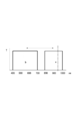
- Fig. 1A is a view illustrating structure of fundus camera according to first and second exemplary embodiment of the present invention.
- Fig. 1B is a view illustrating structure of fundus camera according to first and second exemplary embodiment of the present invention.
- Fig. 2A illustrates characteristics of each wavelength band.
- Fig. 2B illustrates characteristics of each wavelength band.
- Fig. 2C illustrates characteristics of each wavelength band.
- Fig. 2D illustrates characteristics of each wavelength band.
- Fig. 2E illustrates characteristics of each wavelength band.
- Fig. 3A illustrates transmission characteristics of each filter.
- Fig. 3B illustrates transmission characteristics of each filter.
- Fig. 3C illustrates transmission characteristics of each filter.
- Fig. 3D illustrates transmission characteristics of each filter.
- Fig. 1A is a view illustrating a structure of a non-mydriatic fundus camera according to an exemplary embodiment of the present invention.
- an observation light source 1 that includes a halogen lamp to an objective lens 2 that faces a subject's eye is an illumination optical system.
- the observation light source 1 a visible cut filter 3, a diffusion plate 4, a photographic light source 5 that comprises xenon tubes, a lens 6, a diaphragm 7, an eye-lens diaphragm 8, and a mirror 9 are arranged.
- relay lenses 10 and 11, a cornea stop 12, and a perforated mirror 13 are arranged in order.
- a reflecting mirror 14 is provided at the back of the observation light source 1.
- Fig. 2A illustrates transmission characteristics of the visible cut filter 3.
- the visible cut filter 3 does not pass light of visible wavelengths and passes light of near-infrared wavelengths of 680 nm or above.
- an observation and photographing optical system is arranged.
- a photographic diaphragm 15, a focus lens 16 that can move along an optical path, an imaging lens 17, a near-infrared cut filter 18 that can be inserted into and removed from the optical path, and an image capturing unit 19 are arranged.
- the image capturing unit 19 has sensitivity ranging from visible light to near-infrared light that is invisible, and can output moving images and still images.
- An output signal of the image capturing unit 19 is connected to a control unit (also referred to as display control unit) 31 and a monitor (also referred to as display unit) 32.
- An output signal of the control unit 31 is connected to the photographic light source 5, the focus lens 16 via a driving unit 33, and the near-infrared cut filter 18 (hereinafter, filters that select a wavelength of light for focusing on the image capturing unit may be referred to as wavelength selection units) via a driving unit 34.
- a photographing switch 35 for still image photographing is connected to the control unit 31 a photographing switch 35 for still image photographing.
- light flux from the observation light source 1 passes through the visible cut filter 3 and is obtained as a near-infrared wavelength.
- the wavelength is used as illumination light (also referred to as light of a first wavelength).
- illumination light also referred to as light of a first wavelength.
- a fundus of a subject's eye is illuminated.
- the image of the subject's eye is formed on an imaging surface of the image capturing unit 19 by the observation and photographing optical system.
- the near-infrared cut filter 18 is retracted from the optical path by the driving unit 34.
- the operator performs positioning such that the fundus is positioned at a desired point while observing the moving image output from the image capturing unit 19 with the monitor 32.
- the control unit 31 controls the focus lens 16 through the driving unit 33 to perform focusing operation.
- illumination light also referred to as light of a second wavelength
- visible light from the photographic light source 5 is used.
- the control unit 31 performs the focusing operation through the driving unit 33.
- the photographic light source 5 emits light
- the control unit 31 inserts the near-infrared cut filter 18 into the observation and photographing optical system through the driving unit 34.
- the image capturing unit 19 captures a still image, and the captured fundus image is displayed on the monitor 32.
- the control unit 31 stores an amount of movement of the focus lens 16 corresponding to an optical path difference between an arbitrary wavelength within a near-infrared wavelength range a of around 780 to 1000 nm and an arbitrary wavelength within a visible wavelength range b of around 400 to 700 nm shown in Fig. 2B.
- the control unit 31 further moves the focus lens 16 by the stored amount from the in-focus position at the observation through the driving unit 33.
- control unit 31 moves back the focus lens 16 by the above-described amount via the driving unit 33 and retracts the near-infrared cut filter 18 from the optical path via the driving unit 34.
- the driving control of the focus lens 16 by the control unit 31 is not limited to the automatic focusing.
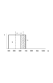
- Fig. 1B illustrates a structure of a fundus camera that can perform autofluorescence photographing according to the second exemplary embodiment of the present invention.
- Reference numerals the same as those in the drawing used in the above-described description represent the same components.
- an autofluorescence excitation filter 41 and an optical path length correction glass 42 which can be inserted into and removed from the optical path, are arranged so that they can be switched.
- an autofluorescence bandpass filter 43 and an optical path length correction glass 44 are arranged so that they can be switched.
- Output of the control unit 31 is connected to the autofluorescence excitation filter 41 and the optical path length correction glass 42 through a driving unit 45, and also connected to the autofluorescence bandpass filter 43 and the optical path length correction glass 44 through the driving unit 46.
- Fig. 3A illustrates transmission characteristics of the autofluorescence excitation filter 41.
- the autofluorescence excitation filter 41 transmits wavelengths of around 580 nm and blocks the other wavelengths.
- Fig. 3B illustrates transmission characteristics of the autofluorescence bandpass filter 43.
- the autofluorescence bandpass filter 43 transmits wavelengths of around 620 to 700 nm and blocks the other wavelengths.
- the dotted line shows the transmission characteristics of the autofluorescence excitation filter 41 in Fig. 3A. It shows that the transmission band in Fig. 3B does not overlap with the transmission band of the autofluorescence bandpass filter 43.
- the control unit 31 inserts the optical path length correction glass 42 into the optical path through the driving unit 45.
- the control unit 31 inserts the optical path length correction glass 44 into the optical path through the driving unit 46.
- the operator performs positioning such that the image of the fundus is positioned at a desired point while observing the moving image output from the image capturing unit 19 with the monitor 32. Then, the control unit 31 controls the focus lens 16 through the driving unit 33 to perform focusing operation.
- the control unit 31 switches the optical path length correction glass 42 to the autofluorescence excitation filter 41 via the driving unit 46.
- the control unit 31 switches the optical path length correction glass 44 to the autofluorescence bandpass filter 43 via the driving unit 46 in synchronization with the shooting, the control unit 31 performs focusing control of the focus lens 16.
- the photographic light source 5 emits light and still image photographing is performed.
- the image captured as an autofluorescence image generated at the fundus is displayed on the monitor 32.
- An optical path difference is generated due to a difference between a wavelength within the near-infrared wavelength range a of about 780 to 1000 nm and a wavelength within an autofluorescence fluorescence wavelength range c of about 620 to 700 nm shown in Fig. 2C.
- the control unit 31 stores a movement amount of the focus lens 16 corresponding to the optical path difference. In synchronization with the shooting, the control unit 31 moves the focus lens 16 by the movement amount.
- the control unit 31 switches the autofluorescence excitation filter 41 to the optical path length correction glass 42.
- the control unit 31 retracts the autofluorescence bandpass filter 43 and moves back the focus lens 16 by the movement amount.
- the near-infrared filter can be provided at a desired position in the illumination optical system or the observation and photographing optical system, and the thickness of the optical filter is not limited to a certain thickness.
- the visible cut filter 3 in front of the observation light source 1 is removed from Fig. 1B.
- illumination light from the observation light source 1 selectively includes visible light.
- illumination light also referred to as light of a first wavelength
- visible light is used.
- the control unit 31 performs control to insert the optical path length correction glass 42 into the optical path via the driving unit 45.
- the control unit 31 performs control to insert the optical path length correction glass 44 into the optical path via the driving unit 46.
- the operator performs positioning such that the image of the fundus is positioned at a desired point while observing the moving image output from the image capturing unit 19 with the monitor 32. Then, the control unit 31 drives the focus lens 16 to perform focusing operation.
- illumination light also referred to as light of a second wavelength
- visible light is used.
- the control unit 31 switches the optical path length correction glass 42 to the autofluorescence excitation filter 41 via the driving unit 45.
- the control unit 31 switches the optical path length correction glass 44 to the autofluorescence bandpass filter 43 via the driving unit 46.
- the control unit 31 performs control to move the focus lens 16. Simultaneously, the photographic light source 5 emits light and the still image photographing is performed. The captured image is displayed on the monitor 32.
- the control unit 31 stores a movement amount corresponding to an optical path difference generated due to a difference between a wavelength within the visible wavelength range b of around 400 to 700 nm and a wavelength within the autofluorescence fluorescence wavelength range c of around 620 to 700 nm shown in Fig. 2D. In synchronization with the shooting, the control unit 31 moves the focus lens 16 by the stored movement amount.
- the control unit 31 switches the autofluorescence excitation filter 41 to the optical path length correction glass 42. Further, the control unit 31 switches the autofluorescence bandpass filter 43 to the optical path length correction glass 44 and moves back the focus lens 16 by the stored movement amount.
- a fundus camera includes an infrared fluorescent (ICG (Indocyanine green)) excitation filter 51 and an infrared fluorescent (ICG) bandpass filter 53 in replace of the autofluorescence excitation filter 41 and the autofluorescence bandpass filter 43 illustrated in Fig. 1B respectively.
- ICG infrared fluorescent
- the infrared fluorescent (ICG) bandpass filter 53 and the optical path length correction glass 44 are arranged so that they can be switched.
- the infrared fluorescent excitation filter 51 and the optical path length correction glass 42 are driven in response to an instruction by the control unit 31 by the driving unit 45.
- the infrared fluorescent bandpass filter 53 and the optical path length correction glass 44 are driven by the driving unit 46.
- Fig. 3C illustrates transmission characteristics of the infrared fluorescent excitation filter 51.
- the infrared fluorescent excitation filter 51 transmits wavelengths of around 720 to 800 nm and blocks the other wavelengths.
- Fig. 3D illustrates transmission characteristics of the infrared fluorescent bandpass filter 53.
- the infrared fluorescent (ICG) bandpass filter 53 transmits wavelengths of around 820 to 900 nm and blocks the other wavelengths.
- the dotted line shows the transmission characteristics of the infrared fluorescent excitation filter 51 in Fig. 3D. It shows that the transmission band in Fig. 3D does not overlap with the transmission band of the infrared fluorescent bandpass filter 53.
- near-infrared wavelength is used as illumination light.
- the control unit 31 inserts the optical path length correction glass 42 into the optical path via the driving unit 45.
- the control unit 31 inserts the optical path length correction glass 44 via the driving unit 46.
- the operator performs positioning such that the image of the fundus is positioned at a desired point while observing the moving image output from the image capturing unit 19 with the monitor 32. Then, the control unit 31 drives the focus lens 16 to perform focusing operation.
- the control unit 31 switches the optical path length correction glass 42 to the infrared fluorescent excitation filter 51 via the driving unit 45.
- the control unit 31 switches the optical path length correction glass 44 to the infrared fluorescent bandpass filter 53 via the driving unit 46.
- the control unit 31 performs focusing control of the focus lens 16. Simultaneously, the photographic light source 5 emits light and the still image photographing is performed. The captured image is displayed on the monitor 32.
- the control unit 31 stores a movement amount corresponding to an optical path difference generated due to a difference between a wavelength within the near-infrared wavelength range a of around 780 to 1000 nm and a wavelength within an infrared fluorescence fluorescence wavelength range d of around 820 to 900 nm shown in Fig. 2E. In synchronization with the shooting, the control unit 31 moves the focus lens 16 by the movement amount.
- the control unit 31 switches the infrared fluorescent excitation filter 51 to the optical path length correction glass 42. Further, the control unit 31 switches the infrared fluorescent bandpass filter 53 to the optical path length correction glass 44. Further, the control unit 31 moves back the focus lens 16 to the original position by the movement amount.
- a dichroic mirror that can be inserted into and removed from the observation and photographing optical path can be used to correct the optical path when a light flux splitting unit for optical path splitting is inserted or retracted.
- aspects of the present invention can also be realized by a computer of a system or apparatus (or devices such as a CPU or MPU) that reads out and executes a program recorded on a memory device to perform the functions of the above-described embodiment(s), and by a method, the steps of which are performed by a computer of a system or apparatus by, for example, reading out and executing a program recorded on a memory device to perform the functions of the above-described embodiment(s).
- the program is provided to the computer for example via a etwork or from a recording medium of various types serving as the memory device (e.g., computer-readable medium).
Abstract
Description
Other Embodiments
Claims (12)
- An ophthalmologic imaging apparatus that captures an image of a subject's eye, the apparatus comprising:
a focusing unit configured to focus light returned from the subject's eye that is illuminated by the light of a first wavelength, onto an imaging unit; and
a moving unit configured to move the focusing unit based on an optical path length difference between the light of the first wavelength and the light of a second wavelength that is different from the first wavelength when light returned from the subject's eye that is illuminated by the light of the second wavelength is focused onto the imaging unit. - The ophthalmologic imaging apparatus according to claim 1, wherein the subject's eye and the imaging unit are conjugate to each other when the light returned from the subject's eye that is illuminated by the light of the first and second wavelengths is focused onto the imaging unit.
- The ophthalmologic imaging apparatus according to claim 1, further comprising:
an illumination optical system configured to irradiate the subject's eye with the light of the first and second wavelengths. - The ophthalmologic imaging apparatus according to claim 1, further comprising:
an observation light source that generates near-infrared light or visible light that contains the light of the first wavelength;
a photographing light source that generates visible light that contains the light of the second wavelength,
wherein, after the subject's eye is observed using the observation light source, the image of the subject's eye is captured using the photographing light source. - The ophthalmologic imaging apparatus according to claim 1, wherein the focusing unit further comprises a focus lens that can move along the optical path.
- The ophthalmologic imaging apparatus according to claim 1, further comprising:
a display control unit configured to display a moving image or a still image generated based on an output signal from the imaging unit, on a display unit. - The ophthalmologic imaging apparatus according to claim 1, further comprising:
a wavelength selection unit configured to select the wavelength of the light to be focused on the imaging unit; and
a control unit configured to control the wavelength selection unit to insert or retract the wavelength selection unit into or from the optical path. - An ophthalmologic imaging method for capturing an image of a subject's eye, the method comprising:
irradiating the subject's eye with the light of a first wavelength;
focusing onto an imaging unit based on an optical path length difference between the light of the first wavelength and the light of a second wavelength that is different from the first wavelength; and
irradiating the subject's eye with the light of the second wavelength. - The ophthalmologic imaging method according to claim 8, wherein the subject's eye and the imaging unit are conjugate to each other when the light returned from the subject's eye that is illuminated by the light of the first and second wavelengths is focused onto the imaging unit.
- A computer program that executes the ophthalmologic imaging method according to claim 8 using a computer.
- An ophthalmologic imaging apparatus that captures an image of a subject's eye, the apparatus comprising:
an illumination optical system configured to irradiate the subject's eye with the light of a first wavelength and the light of a second wavelength that is different from the first wavelength;
a photographing optical system having a focusing unit configured to focus light returned from the subject's eye that is illuminated by the illumination optical system, onto an imaging unit; and
a moving unit configured to move the focusing unit based on an optical path length difference between the light of the first wavelength and the light of the second wavelength. - The ophthalmologic imaging apparatus according to claim 11, wherein the fundus of the subject's eye and an imaging surface of the imaging unit are conjugate to each other when the light returned from the subject's eye that is illuminated by the light of the first and second wavelengths is focused onto the imaging unit.
Priority Applications (5)
| Application Number | Priority Date | Filing Date | Title |
|---|---|---|---|
| US13/119,635 US9332906B2 (en) | 2009-06-11 | 2010-06-10 | Ophthalmologic imaging apparatus and ophthalmologic imaging method |
| EP10731609.3A EP2440111B1 (en) | 2009-06-11 | 2010-06-10 | Ophthalmologic imaging apparatus and ophthalmologic imaging method |
| KR1020127000584A KR101377148B1 (en) | 2009-06-11 | 2010-06-10 | Ophthalmologic imaging apparatus and ophthalmologic imaging method |
| CN201080026151.4A CN102458228B (en) | 2009-06-11 | 2010-06-10 | Ophthalmologic imaging apparatus and ophthalmologic imaging method |
| US15/099,392 US9782072B2 (en) | 2009-06-11 | 2016-04-14 | Ophthalmologic imaging apparatus and ophthalmologic imaging method |
Applications Claiming Priority (4)
| Application Number | Priority Date | Filing Date | Title |
|---|---|---|---|
| JP2009140270 | 2009-06-11 | ||
| JP2009-140270 | 2009-06-11 | ||
| JP2010-130294 | 2010-06-07 | ||
| JP2010130294A JP5335734B2 (en) | 2009-06-11 | 2010-06-07 | Ophthalmic imaging apparatus and ophthalmic imaging method |
Related Child Applications (2)
| Application Number | Title | Priority Date | Filing Date |
|---|---|---|---|
| US13/119,635 A-371-Of-International US9332906B2 (en) | 2009-06-11 | 2010-06-10 | Ophthalmologic imaging apparatus and ophthalmologic imaging method |
| US15/099,392 Continuation US9782072B2 (en) | 2009-06-11 | 2016-04-14 | Ophthalmologic imaging apparatus and ophthalmologic imaging method |
Publications (1)
| Publication Number | Publication Date |
|---|---|
| WO2010143443A1 true WO2010143443A1 (en) | 2010-12-16 |
Family
ID=42673166
Family Applications (1)
| Application Number | Title | Priority Date | Filing Date |
|---|---|---|---|
| PCT/JP2010/003884 WO2010143443A1 (en) | 2009-06-11 | 2010-06-10 | Ophthalmologic imaging apparatus and ophthalmologic imaging method |
Country Status (6)
| Country | Link |
|---|---|
| US (2) | US9332906B2 (en) |
| EP (1) | EP2440111B1 (en) |
| JP (1) | JP5335734B2 (en) |
| KR (1) | KR101377148B1 (en) |
| CN (1) | CN102458228B (en) |
| WO (1) | WO2010143443A1 (en) |
Cited By (1)
| Publication number | Priority date | Publication date | Assignee | Title |
|---|---|---|---|---|
| JP2014147850A (en) * | 2014-05-28 | 2014-08-21 | Nidek Co Ltd | Fundus photographing apparatus |
Families Citing this family (9)
| Publication number | Priority date | Publication date | Assignee | Title |
|---|---|---|---|---|
| JP5021007B2 (en) * | 2009-08-27 | 2012-09-05 | キヤノン株式会社 | Ophthalmic photographing apparatus and camera used in the ophthalmic photographing apparatus |
| JP5371638B2 (en) * | 2009-09-01 | 2013-12-18 | キヤノン株式会社 | Ophthalmic imaging apparatus and method |
| JP2012050621A (en) * | 2010-08-31 | 2012-03-15 | Canon Inc | Imaging unit and control method thereof |
| JP6143421B2 (en) | 2012-03-30 | 2017-06-07 | キヤノン株式会社 | Optical coherence tomography apparatus and method |
| JP6124548B2 (en) * | 2012-10-17 | 2017-05-10 | キヤノン株式会社 | Ophthalmic imaging method and ophthalmic apparatus |
| JP6436613B2 (en) * | 2012-11-09 | 2018-12-12 | キヤノン株式会社 | Ophthalmic photographing apparatus and control method of ophthalmic photographing apparatus |
| JP6243087B2 (en) * | 2015-04-23 | 2017-12-06 | 富士フイルム株式会社 | Imaging apparatus, image processing method of imaging apparatus, and program |
| JP2017159089A (en) * | 2017-05-10 | 2017-09-14 | キヤノン株式会社 | Fundus imaging apparatus |
| CN113558567B (en) * | 2019-12-30 | 2023-07-25 | 深圳硅基智能科技有限公司 | Fundus camera for collecting fundus image |
Citations (6)
| Publication number | Priority date | Publication date | Assignee | Title |
|---|---|---|---|---|
| US4436388A (en) * | 1980-04-25 | 1984-03-13 | Canon Kabushiki Kaisha | Eye-fundus camera provided with automatic focusing function |
| JPH08256988A (en) | 1995-03-27 | 1996-10-08 | Topcon Corp | Tv relay lens unit for ophthalmologic photographing |
| JPH0966030A (en) | 1995-09-01 | 1997-03-11 | Kowa Co | Fundus camera |
| JPH1043139A (en) | 1997-05-26 | 1998-02-17 | Topcon Corp | Ophthalmologic device |
| US20020047989A1 (en) * | 2000-10-20 | 2002-04-25 | Naohisa Shibata | Fundus camera |
| US20070146535A1 (en) * | 1996-10-31 | 2007-06-28 | Nidek Co., Ltd. | Fundus camera |
Family Cites Families (9)
| Publication number | Priority date | Publication date | Assignee | Title |
|---|---|---|---|---|
| JPS5778839A (en) * | 1980-11-01 | 1982-05-17 | Canon Kk | Eye bottom camera |
| JPS60207636A (en) * | 1984-03-30 | 1985-10-19 | キヤノン株式会社 | Eyeground camera |
| JP2738849B2 (en) | 1988-10-06 | 1998-04-08 | 株式会社トプコン | Ophthalmic examination device |
| JPH02268733A (en) * | 1989-04-10 | 1990-11-02 | Canon Inc | Fundus camera having automatic focus matching function |
| JPH078457A (en) * | 1993-06-16 | 1995-01-13 | Topcon Corp | Ophthalmological measuring instrument |
| JPH07313466A (en) * | 1994-05-20 | 1995-12-05 | Nikon Corp | Fundus oculi photographing system |
| JPH08150121A (en) * | 1994-11-28 | 1996-06-11 | Canon Inc | Eyeground camera |
| JPH09289973A (en) * | 1996-04-26 | 1997-11-11 | Canon Inc | Eye ground camera |
| JP2008035944A (en) * | 2006-08-02 | 2008-02-21 | Topcon Corp | System for ophthalmologic imaging |
-
2010
- 2010-06-07 JP JP2010130294A patent/JP5335734B2/en active Active
- 2010-06-10 US US13/119,635 patent/US9332906B2/en active Active
- 2010-06-10 CN CN201080026151.4A patent/CN102458228B/en not_active Expired - Fee Related
- 2010-06-10 KR KR1020127000584A patent/KR101377148B1/en active IP Right Grant
- 2010-06-10 WO PCT/JP2010/003884 patent/WO2010143443A1/en active Application Filing
- 2010-06-10 EP EP10731609.3A patent/EP2440111B1/en active Active
-
2016
- 2016-04-14 US US15/099,392 patent/US9782072B2/en active Active
Patent Citations (6)
| Publication number | Priority date | Publication date | Assignee | Title |
|---|---|---|---|---|
| US4436388A (en) * | 1980-04-25 | 1984-03-13 | Canon Kabushiki Kaisha | Eye-fundus camera provided with automatic focusing function |
| JPH08256988A (en) | 1995-03-27 | 1996-10-08 | Topcon Corp | Tv relay lens unit for ophthalmologic photographing |
| JPH0966030A (en) | 1995-09-01 | 1997-03-11 | Kowa Co | Fundus camera |
| US20070146535A1 (en) * | 1996-10-31 | 2007-06-28 | Nidek Co., Ltd. | Fundus camera |
| JPH1043139A (en) | 1997-05-26 | 1998-02-17 | Topcon Corp | Ophthalmologic device |
| US20020047989A1 (en) * | 2000-10-20 | 2002-04-25 | Naohisa Shibata | Fundus camera |
Cited By (1)
| Publication number | Priority date | Publication date | Assignee | Title |
|---|---|---|---|---|
| JP2014147850A (en) * | 2014-05-28 | 2014-08-21 | Nidek Co Ltd | Fundus photographing apparatus |
Also Published As
| Publication number | Publication date |
|---|---|
| CN102458228B (en) | 2014-10-22 |
| US9332906B2 (en) | 2016-05-10 |
| US20110170063A1 (en) | 2011-07-14 |
| EP2440111A1 (en) | 2012-04-18 |
| KR101377148B1 (en) | 2014-04-01 |
| US20160228002A1 (en) | 2016-08-11 |
| JP2011015955A (en) | 2011-01-27 |
| JP5335734B2 (en) | 2013-11-06 |
| CN102458228A (en) | 2012-05-16 |
| US9782072B2 (en) | 2017-10-10 |
| KR20120027499A (en) | 2012-03-21 |
| EP2440111B1 (en) | 2017-04-26 |
Similar Documents
| Publication | Publication Date | Title |
|---|---|---|
| US9782072B2 (en) | Ophthalmologic imaging apparatus and ophthalmologic imaging method | |
| JP5084594B2 (en) | Ophthalmic imaging device | |
| US20070019160A1 (en) | Ring light fundus camera | |
| JP5386512B2 (en) | Ophthalmic imaging equipment | |
| JP2010220670A (en) | Fundus camera | |
| WO2012118010A1 (en) | Ophthalmologic imaging apparatus | |
| JP6124548B2 (en) | Ophthalmic imaging method and ophthalmic apparatus | |
| JP3024790B2 (en) | Fundus camera | |
| JP4447172B2 (en) | Fundus camera | |
| JP7098964B2 (en) | Fundus photography device | |
| JP6116188B2 (en) | Fundus imaging device | |
| JP7056242B2 (en) | Fundus photography device | |
| JP5989186B2 (en) | Ophthalmic imaging apparatus and method for controlling ophthalmic imaging apparatus | |
| JP2000232961A (en) | Fundus camera | |
| JP2003210409A (en) | Fundus camera | |
| JP7355194B2 (en) | fundus imaging device | |
| JP4612371B2 (en) | Ophthalmic imaging equipment | |
| JP3269675B2 (en) | Fundus camera | |
| JP5755200B2 (en) | Ophthalmic imaging apparatus and method | |
| JP2014226371A (en) | Ophthalmic photographing apparatus | |
| JP2022042896A (en) | Fundus photography device | |
| JP2014226370A (en) | Ophthalmic photographing apparatus |
Legal Events
| Date | Code | Title | Description |
|---|---|---|---|
| WWE | Wipo information: entry into national phase |
Ref document number: 201080026151.4 Country of ref document: CN |
|
| 121 | Ep: the epo has been informed by wipo that ep was designated in this application |
Ref document number: 10731609 Country of ref document: EP Kind code of ref document: A1 |
|
| WWE | Wipo information: entry into national phase |
Ref document number: 13119635 Country of ref document: US |
|
| NENP | Non-entry into the national phase |
Ref country code: DE |
|
| REEP | Request for entry into the european phase |
Ref document number: 2010731609 Country of ref document: EP |
|
| WWE | Wipo information: entry into national phase |
Ref document number: 2010731609 Country of ref document: EP |
|
| ENP | Entry into the national phase |
Ref document number: 20127000584 Country of ref document: KR Kind code of ref document: A |