WO2010137114A1 - Controller, in-vehicle device, system and method - Google Patents
Controller, in-vehicle device, system and method Download PDFInfo
- Publication number
- WO2010137114A1 WO2010137114A1 PCT/JP2009/059608 JP2009059608W WO2010137114A1 WO 2010137114 A1 WO2010137114 A1 WO 2010137114A1 JP 2009059608 W JP2009059608 W JP 2009059608W WO 2010137114 A1 WO2010137114 A1 WO 2010137114A1
- Authority
- WO
- WIPO (PCT)
- Prior art keywords
- cable
- length
- usb
- voltage
- vehicle device
- Prior art date
Links
Images


Classifications
-
- B—PERFORMING OPERATIONS; TRANSPORTING
- B60—VEHICLES IN GENERAL
- B60R—VEHICLES, VEHICLE FITTINGS, OR VEHICLE PARTS, NOT OTHERWISE PROVIDED FOR
- B60R16/00—Electric or fluid circuits specially adapted for vehicles and not otherwise provided for; Arrangement of elements of electric or fluid circuits specially adapted for vehicles and not otherwise provided for
- B60R16/02—Electric or fluid circuits specially adapted for vehicles and not otherwise provided for; Arrangement of elements of electric or fluid circuits specially adapted for vehicles and not otherwise provided for electric constitutive elements
- B60R16/023—Electric or fluid circuits specially adapted for vehicles and not otherwise provided for; Arrangement of elements of electric or fluid circuits specially adapted for vehicles and not otherwise provided for electric constitutive elements for transmission of signals between vehicle parts or subsystems
-
- H—ELECTRICITY
- H02—GENERATION; CONVERSION OR DISTRIBUTION OF ELECTRIC POWER
- H02H—EMERGENCY PROTECTIVE CIRCUIT ARRANGEMENTS
- H02H3/00—Emergency protective circuit arrangements for automatic disconnection directly responsive to an undesired change from normal electric working condition with or without subsequent reconnection ; integrated protection
- H02H3/26—Emergency protective circuit arrangements for automatic disconnection directly responsive to an undesired change from normal electric working condition with or without subsequent reconnection ; integrated protection responsive to difference between voltages or between currents; responsive to phase angle between voltages or between currents
- H02H3/32—Emergency protective circuit arrangements for automatic disconnection directly responsive to an undesired change from normal electric working condition with or without subsequent reconnection ; integrated protection responsive to difference between voltages or between currents; responsive to phase angle between voltages or between currents involving comparison of the voltage or current values at corresponding points in different conductors of a single system, e.g. of currents in go and return conductors
- H02H3/325—Emergency protective circuit arrangements for automatic disconnection directly responsive to an undesired change from normal electric working condition with or without subsequent reconnection ; integrated protection responsive to difference between voltages or between currents; responsive to phase angle between voltages or between currents involving comparison of the voltage or current values at corresponding points in different conductors of a single system, e.g. of currents in go and return conductors involving voltage comparison
Definitions
- the present invention relates to an in-vehicle device, a control device that controls communication with various devices connected to the in-vehicle device via, for example, USB, and a system including the in-vehicle device.
- USB devices are connected to in-vehicle devices via USB (Universal Serial Bus).
- In-vehicle devices include car audio and car navigation, and USB devices include hard disks (HD), music players, and sensors.
- HD hard disks
- the in-vehicle device has a USB control unit (USB control device).
- the USB control unit is connected to the USB connector.
- the USB cable includes a power line, a communication line, and a ground line.
- the USB control unit is connected to a power line that supplies power to the USB device.
- the USB control unit supplies power of +5 V (maximum current capacity 0.5 A) to the USB device connected to the in-vehicle device via the USB connector and the power line.
- USB devices operate with power supplied from the USB control unit.
- the guaranteed operating voltage range for USB devices follows the standard. Generally, it is DC + 5V ⁇ 5%.
- the standard includes USB 2.0.
- a voltage drop occurs in the USB cable.
- the voltage drop may cause the power supply voltage supplied to the USB device via the power cable to drop below an allowable value defined in the standard.
- the power supply voltage supplied to the USB device decreases, the USB device may not operate. In other words, the power consumed by the line resistance proportional to the USB cable length may cause the power supply voltage from the power supply of the USB control unit to drop, and the USB device operation guarantee voltage + 5V ⁇ 5% may not be satisfied.
- the maximum transmission distance between the USB control unit and the USB device is defined by the standard. For example, in USB 2.0, the maximum transmission distance is 5 m. Since the maximum transmission distance corresponds to the length of the USB cable connecting the USB control unit and the USB device, it is necessary to arrange the USB control unit and the USB device so as not to exceed the length.
- the USB control unit and the USB device may not be placed close to each other. It is also assumed that the maximum transmission distance is exceeded between the USB control unit and the USB device. If the distance between the USB control unit and the USB device exceeds the maximum transmission distance, the signal transmitted by the signal cable is attenuated, and the amplitude may be less than the allowable value specified in the standard.
- an amplifying device called a repeater or a booster must be installed between the USB control unit and the USB device.
- the repeater compensates for signal attenuation
- the booster compensates for voltage drop.
- the present invention has been made in view of the above points, and even when the distance between the control unit and the device exceeds the maximum transmission distance, the repeater and / or the booster are not required, and the control unit and the device It is an object of the present invention to provide a control device, an in-vehicle device, a system, and a method that can ensure communication quality between the devices.
- This control device A control device that controls communication between an in-vehicle device and a device connected to the in-vehicle device via a cable, A cable length detector for detecting the length of the cable; A communication control unit that performs control for ensuring communication quality between the in-vehicle device and the device based on the length of the cable detected by the cable length detection unit.
- This control device A control device that controls communication between an in-vehicle device and a device connected to the in-vehicle device via a cable, A cable length setting section for setting the cable length; A communication control unit that performs control for ensuring communication quality between the in-vehicle device and the device based on the cable length set by the cable length setting unit.
- This in-vehicle device has the above control device.
- This system A system having an in-vehicle device and a cable connected to the in-vehicle device and connected to the other end of the device,
- the cable is A detection line for detecting the length of the cable;
- a resistor having a resistance value corresponding to the length of the cable connected to the detection line and grounded at the other end;
- the in-vehicle device is A power supply for applying a voltage to the resistor;
- a second resistor connected to the power source and having the other end connected to the detection line;
- a voltage measuring unit that measures a voltage applied to the resistor when a voltage is applied by the power source; and A table showing the correspondence between the value of the voltage applied to the resistor and the length of the cable;
- a cable length detector for detecting the length of the cable;
- a communication control unit that performs control to ensure communication quality between the in-vehicle device and the device based on the length of the cable detected by the cable length detection unit;
- the cable length detecting unit detects the length of the cable by
- This system A system having an in-vehicle device and a cable connected to the in-vehicle device and connected to the other end of the device,
- the cable is A detection line for detecting the length of the cable,
- the detection line has a resistance value corresponding to the length of the cable
- the in-vehicle device is A power source for applying a voltage to the detection line;
- a second resistor connected to the power source and having the other end connected to the detection line;
- a voltage measuring unit for measuring a voltage applied to the detection line when a voltage is applied by the power source; and A table showing the correspondence between the value of the voltage applied to the detection line and the length of the cable;
- a cable length detector for detecting the length of the cable;
- a communication control unit that performs control to ensure communication quality between the in-vehicle device and the device based on the length of the cable detected by the cable length detection unit;
- the cable length detecting unit detects the length of the cable by referring to the table and obtaining the length of the
- This method A method in a control device for controlling communication between an in-vehicle device and a device connected to the in-vehicle device via a cable, A cable length detection step for detecting the length of the cable; A communication control step for performing control for ensuring communication quality between the in-vehicle device and the device based on the length of the cable detected by the cable length detection step.
- This method A method in a control device for controlling communication between an in-vehicle device and a device connected to the in-vehicle device via a cable, A cable length setting step for setting the cable length; A communication control step for performing control for ensuring communication quality between the in-vehicle device and the device based on the cable length set in the cable length setting step.
- control device in-vehicle device, system, and method, even when the maximum transmission distance is exceeded between the control unit and the device, the repeater and / or the booster are not required, and the control unit and the device can be connected. Communication quality can be secured.
- 1 is a block diagram showing a system to which an in-vehicle device, a USB cable, and a USB device according to an embodiment are applied. It is a functional block diagram which shows the microcomputer of the vehicle equipment according to one Example. It is explanatory drawing which shows control of the amplification factor of the transmission signal in the vehicle equipment according to one Example. It is explanatory drawing which shows control of the power supply voltage supplied to the power wire in the vehicle equipment according to one Example. It is a flowchart which shows operation
- movement of the vehicle equipment according to one Example. 1 is a block diagram showing a system to which an in-vehicle device, a USB cable, and a USB device according to an embodiment are applied.
- 1 is a block diagram showing a system to which an in-vehicle device, a USB cable, and a USB device according to an embodiment are applied.
- 1 is a block diagram showing a system to which an in-vehicle device, a USB cable, and a USB device according to an embodiment are applied.
- 1 is a block diagram showing a system to which an in-vehicle device, a USB cable, and a USB device according to an embodiment are applied. It is a flowchart which shows operation
- 1 is a block diagram showing a system to which an in-vehicle device, a USB cable, and a USB device according to an embodiment are applied.
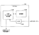
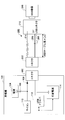
- FIG. 1 is a functional block diagram showing a system to which an in-vehicle device, a USB cable, and a USB device according to the present embodiment are applied.
- a system to which an in-vehicle device, a USB cable, and a USB device according to the present embodiment are applied.
- the present invention can be applied when controlling communication with a device connected to a vehicle-mounted device via a cable.
- This system has an in-vehicle device 100, a USB cable 200, and a USB device 300.
- the in-vehicle device 100 has a USB control device.
- the USB control device includes a connector 102, a power supply 104, a resistor 106, a diode 108, a microcomputer 110, a USB driver 112, and a variable power supply 114.
- the USB cable 200 includes a connector 202, a cable length detection line 204, a communication line (D +, D-) 206, a power supply line (VBUS) 208, and a USB connector 210.
- the GND line is omitted.
- an ID line may be included.
- the USB connector 210 includes a cable length detection resistor component 212 that is connected to the cable length detection line 204 and is grounded at the other end.
- the maximum length of the USB cable is defined by the USB standard. For example, USB 2.0 specifies 5m. Therefore, the USB cable 200 for connecting the in-vehicle device 100 and the USB device 300 should be used at 5 m or less. However, when the vehicle-mounted device 100 is installed in the vehicle, a USB cable that connects the connector 102 and the USB driver 112 and / or the variable power source 114 may be incorporated into the vehicle. When a USB cable that connects between the connector 102 and the USB driver 112 and / or the variable power supply 114 is incorporated in a vehicle, the connector is used even if the length of the USB cable 200 connected to the in-vehicle device 100 is 5 m. Since the length of the USB cable connecting between the terminal 102 and the USB driver 112 and / or the variable power source 114 is extended, the length substantially exceeds 5 m.
- the in-vehicle device 100 detects the length of the USB cable.
- the length of the USB cable is the length of the USB cable 200 connected to the connector 102 and the other end connected to the USB device 300.
- the in-vehicle device 100 adds the length of the USB cable connecting the connector 102 and the USB driver 112 and / or the variable power source 114 to the detected length of the USB cable 200, and based on the total length, Control is performed to ensure communication quality between the in-vehicle device 100 and the USB device 300.
- control for ensuring the communication quality between the in-vehicle device 100 and the USB device 300 the amplification factor of the signal transmitted through the communication line 206 and / or the power supply voltage supplied to the power supply line 208 are set.
- An example of control will be described.
- the present invention is not limited to the amplification factor of the signal transmitted through the communication line 206 and / or the power supply voltage supplied to the power supply line 208, and any control that can be performed to ensure the communication quality between the in-vehicle device 100 and the USB device 300. Parameters can be controlled.
- the USB cable 200 is connected to the connector 102.
- the connector 102 may be a female terminal of a USB A terminal.
- the connector 102 has five pins (PIN).
- the pins include a pin connected to the power supply line 208, two pins connected to the communication line 206, a pin connected to the cable length detection line 204, and a pin connected to GND (not shown). .
- the power supply 104 applies a voltage.
- the power source 104 is connected to the anode side of the diode 108 via the resistor 106, and the cathode side of the diode 108 is connected to the connector 102.
- the connector 102 is connected to the connector 202 of the USB cable 200, the cathode side of the diode 108 and the cable length detection line 204 are connected.
- the microcomputer 110 is connected to the anode side of the diode 108.
- the microcomputer 110 measures the voltage on the anode side of the diode 108.
- the microcomputer 110 measures the voltage applied to the cable length detection line 204 and the resistor 212. Then, the microcomputer 110 determines the length of the USB cable based on the voltage.
- FIG. 2 is a functional block diagram showing an example of the microcomputer 110 of the in-vehicle device 100.
- the microcomputer 110 includes an analog / digital converter (A / D) 1102, a USB cable length determination unit 1104, and a storage unit 1106.
- a / D analog / digital converter
- USB cable length determination unit 1104 USB cable length determination unit
- storage unit 1106 storage unit
- a / D 1102 is connected to the anode side of the diode 108.
- the A / D 1102 acquires the voltage value on the anode side of the diode 108 and converts it into a digital value.
- the A / D 1102 inputs the voltage value on the anode side of the diode 108 converted into a digital value to the USB cable length determination unit 114.
- the power source 104 applies a voltage via the resistor 106.
- the resistor 212 By connecting the in-vehicle device 100 and the USB cable 200, the resistor 212 having one end grounded is connected to the cathode side of the diode 108 via the cable length detection line 204.
- the resistance value of the resistor 212 is set corresponding to the cable length of the USB cable 200.
- the resistance value of the resistor 212 can be obtained from the potential on the anode side of the diode 108. . Since the resistance value of the resistor 212 can be obtained, the cable length of the USB cable 200 corresponding to the resistance value of the resistor 212 can be obtained.
- the storage unit 116 stores a table in which the anode side potential of the diode 108 and the resistance value of the resistor 212 are associated with each other, and a table in which the resistance value of the resistor 212 and the cable length of the USB cable 200 are associated with each other.
- the Both tables may be integrated into one table.
- a table in which the anode side potential of the diode 108 and the cable length of the USB cable 200 are associated with each other is stored.
- the USB cable length determination unit 114 refers to the table stored in the storage unit 116 and obtains the resistance value of the resistor 212 corresponding to the anode-side potential of the diode 108 input by the A / D 1102. Then, the USB cable length determination unit 114 obtains the cable length of the USB cable 200 corresponding to the resistance value of the resistor 212. The USB cable length determination unit 114 inputs the cable length of the USB cable 200 to the USB driver 112 and the variable power source 114.
- the USB driver 112 controls the amplification factor of the signal supplied to the USB cable 200.
- half-duplex transmission is applied as a communication mode.
- data cannot be transmitted or received from both sides at the same time, and transmission from only one direction can be performed by dividing time.
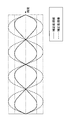
- FIG. 3 shows an example of a signal waveform of data transmitted by the in-vehicle device 100.
- a solid line is a waveform before correction processing.
- the waveform is before the gain is controlled in the in-vehicle device 100.
- the broken line is the waveform after the correction process. In other words, it is a waveform after the amplification factor is controlled in the in-vehicle device 100.
- Both waveforms are waveforms detected by the USB connector 210.
- the USB driver 112 estimates the attenuation amount of the transmission signal generated in the communication line 206 of the USB cable 200 based on the cable length of the USB cable 200 input by the microcomputer 110.
- the USB driver 112 estimates the attenuation amount of the transmission signal generated in the communication line 206 of the USB cable 200 including the length of the USB cable connecting the connector 102 and the USB driver 112 and / or the variable power supply 114. To do.
- the USB driver 112 amplifies the data to correct the attenuation.
- a table in which the cable length is associated with the amplification factor for the transmission signal may be prepared.
- the USB driver 112 amplifies the USB connector 210 of the USB cable 200 connected to the in-vehicle device 100 so that the amplitude is stipulated in the standard. For example, when the waveform after attenuation is estimated as indicated by a solid line, the USB driver 112 amplifies the waveform to be indicated by a broken line.
- the USB connector 210 may satisfy the amplitude defined in the standard. If it is estimated that the USB connector 210 satisfies the amplitude defined in the standard, the USB driver 112 may not perform amplification for correcting the attenuation amount. By performing amplification as necessary, power consumption can be reduced.
- the variable power source 114 controls the voltage supplied to the power line 208 of the USB cable 200.
- the supply voltage to the USB device 300 is defined as 5.0 ⁇ 0.25V.
- the variable power supply 114 estimates not only the power line 208 but also a voltage drop in the USB connector 210 and the USB cable connecting the connector 102 and the USB driver 112 and / or the variable power supply 114.
- the variable power source 114 increases the voltage value to correct the voltage drop.
- a table in which the cable length and the voltage value of the power supply voltage are associated may be prepared.
- the variable power supply 114 increases the voltage to be supplied so as to be a voltage specified by the standard at the USB connector 210 of the USB cable 200 connected to the in-vehicle device 100.
- the variable power supply 114 may be boosted using a DC-DC converter or the like, or may be boosted by a regulator type. Any type of power supply can be applied as long as the power supply voltage can be varied.
- the USB connector 210 may satisfy the voltage specified in the standard.
- the variable power source 114 may not increase the voltage for compensating for the voltage drop. Power consumption can be reduced by controlling the power supply voltage as necessary.
- FIG. 4 shows an example of setting the power supply voltage in the in-vehicle device.
- a solid line shows a voltage supplied to a conventional voltage line and an example in which the voltage does not satisfy the standard in the USB connector 210 due to a voltage drop.
- a broken line indicates a voltage supplied to the voltage line in the present embodiment and an example that satisfies the standard in the USB connector 210 even when the voltage drops due to a voltage drop.
- USB cable 200 The USB cable 200 will be described.
- the connector 202 is connected to the in-vehicle device 100.
- the connector 202 may be a USB A male terminal.
- the connector 202 has five pins (PIN) corresponding to the connector 102.
- the pins include a pin connected to the power supply line 208, two pins connected to the communication line 206, a pin connected to the cable length detection line 204, and a pin connected to GND (not shown). .
- the cable length detection line 204 is an electric wire used when the in-vehicle device 100 detects the cable length of the USB cable 200.
- a resistor 212 is connected to the other end of the cable length detection line 204 opposite to the connector 202.
- the cable length detection line 204 is preferably made of a material whose resistance value is small even when the length of the cable length detection line 204 changes. By configuring the cable length detection line 204 with a material having a small change in resistance value due to a change in length, the voltage applied to the cable length detection line 204 can be reduced. Since the voltage applied to the cable length detection line 204 can be reduced, the detection error of the voltage applied to the resistor 212 can be reduced.
- the detection error of the voltage applied to the resistor 212 can be reduced, the detection error of the cable length detected by the voltage applied to the resistor 212 can be reduced.
- a voltage is applied to the resistor 106 and the resistor 212 by the power source 104.
- the microcomputer 110 detects the length of the USB cable 200 by detecting the voltage applied to the resistor 212.
- the communication line 206 is a signal transmission line used for signal transfer.
- the communication line 206 includes a differential pair (D +) and a differential pair (D ⁇ ).
- the power line 208 is an electric wire for supplying power to the USB device 300.
- the USB connector 210 is connected to the USB device 300.
- the USB connector 210 may be, for example, a female terminal of a USB A terminal.
- the USB connector 212 has four pins (PIN).
- the pins include a pin connected to the power supply line 208, two pins connected to the communication line 206, and a pin connected to GND (not shown).
- the resistor 212 is configured by a resistor having a resistance value corresponding to the length of the USB cable length detection line 204.
- the resistor 212 is configured to be integrated with the USB connector 210.
- the type of the USB device 300 is not limited as long as it is a device connected by USB.
- a portable digital music player, a USB memory, and a hard disk (HD: Hard Disk) connected by USB are included.
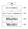
- FIG. 5 shows the operation of the system.
- the operation in the USB control device mounted on the in-vehicle device 100 is mainly described.
- the in-vehicle device 100 and the USB cable 200 are connected (step S502).
- the connector 102 of the in-vehicle device 100 and the connector 202 of the USB cable 200 are connected.
- the in-vehicle device 100 detects the cable length of the USB cable 200 connected to the in-vehicle device 100 (step S504).
- the power source 104 applies a voltage between the resistor 106 and the resistor 212.
- the A / D 1102 converts the voltage value on the anode side of the diode 108 into a digital value.
- the USB cable length determination unit 1104 acquires the cable length of the USB cable 200 corresponding to the voltage value.
- the in-vehicle device 100 controls the amplification factor of the signal transmitted through the communication line 206 (step S506).
- the USB driver 112 obtains the cable length including the length of the USB cable connecting the connector 102 and the USB driver 112 and / or the variable power source 114 based on the cable length detected in step S504. Then, the attenuation amount of the transmission signal is estimated based on the total length of the cable length.
- the USB driver 112 obtains an amplification factor necessary for correcting the attenuation amount.
- the USB driver 112 controls the amplification factor of the signal transmitted through the communication line 206 as necessary according to the amplification factor.
- the in-vehicle device 100 controls the power supply voltage supplied through the power supply line 208 (step S508).
- the variable power source 114 obtains the cable length including the length of the USB cable connecting the connector 102 and the USB driver 112 and / or the variable power source 114 based on the cable length detected in step S504. Then, the voltage drop is estimated based on the total length of the cable length.
- the variable power source 114 obtains a voltage value necessary to compensate for the voltage drop.
- the variable power supply 114 controls the power supply voltage supplied by the power supply line 208 in accordance with the voltage value.
- step S508 a power supply voltage is supplied from the in-vehicle device 100 to the USB device 300, and data is transmitted and received between the in-vehicle device 100 and the USB device 300.
- step S506 and the process of step S508 may be reversed or may be performed simultaneously.
- the USB driver 112 may set the amplification factor with reference to a table indicating the correspondence between the cable length and the amplification factor.
- variable power supply 114 may set the power supply voltage with reference to a table indicating the correspondence between the cable length and the voltage value.
- the transmission characteristics of the USB cable will vary depending on the USB cable manufacturer.
- the resistance value of the resistor 212 corresponding to the length of the USB cable varies depending on the manufacturer.
- the resistor 212 may be configured by a plurality of resistors in order to identify the manufacturer, and the manufacturer may be identified by a combination of the plurality of resistors. For example, you may make it have the 1st resistance for cable length detection, and the 2nd resistance for each manufacturer identification.
- the first resistor and the second resistor may be connected in parallel.
- the storage unit 1106 stores, for each manufacturing company, a table in which the anode-side potential of the diode 108 and the resistance value of the resistor 212 are associated, the resistance value of the resistor 212, and the USB.
- a table in which the cable length of the cable 200 is associated is stored. Both tables may be integrated into one table.
- a table in which the anode side potential of the diode 108 and the cable length of the USB cable 200 are associated with each other is stored. It is also assumed that the transmission characteristics of the USB cable vary depending on the material of the USB cable.
- the cable length of the USB cable 200 may be set for each material.
- the power supply voltage and / or the amplification factor may be set in the microcomputer 110.
- the power supply line 208 is supplied as necessary so as to compensate for the voltage drop in the USB cable.
- the power supply voltage can be controlled. Since the power supply voltage can be controlled so as to compensate for the voltage drop in the USB cable, the communication quality between the in-vehicle device 100 and the USB device 300 can be improved.
- the amplification factor of the signal can be controlled. Since the amplification factor of the transmission signal can be controlled so as to compensate the attenuation of the transmission signal in the communication line of the USB cable, the communication quality between the in-vehicle device and the USB device can be improved.
- the cable length detection line 204 and the resistor 212 are associated with each other, the cable length can be made variable. Then, the in-vehicle device 100 can recognize the cable length.
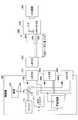
- FIG. 6 is a functional block diagram showing a system to which an in-vehicle device, a USB cable, and a USB device according to this modification are applied.
- This system has an in-vehicle device 100, a USB cable 200, and a USB device 300.
- the in-vehicle device 100 differs from the in-vehicle device described in the first embodiment in that it includes a plurality of connectors.
- FIG. 6 shows three connectors 102 1 , 102 2 , and 102 3 as an example.
- the number of connectors 102 may be two, or four or more.
- FIG. 6 shows one USB cable 200, but it may be two or three.
- the number of USB cables 200 equal to or less than the number of connectors 102 included in the in-vehicle device 100 can be used.
- a USB device 300 is connected to each USB cable 200.
- the in-vehicle device 100 performs control by sequentially switching the plurality of connectors 102.
- the in-vehicle device 100 sequentially determines the amplification factor of the signal transmitted through the communication line 206 of the USB cable 200 connected to each of the connectors 102 1 , 102 2 , and 102 3 and / or the power supply voltage supplied to the power supply line 208.
- Control For example, a USB cable 200 connected to connector 102 1 for the driver's seat, a USB cable 200 connected to connector 102 2 passenger, the USB cable 200 connected to connector 102 3 may be a rear seat .
- the driver's USB device 300 is connected to the USB connector 210 of the driver's USB cable 200
- the USB device 300 of the passenger's seat is connected to the USB connector 210 of the passenger's USB cable 200.
- the USB device 300 of the person in the rear seat is connected to the USB connector 210 of the USB cable 200 for the rear seat.
- the length of 200 is also different.
- the microcomputer 110 sequentially detects the cable length of the USB cable 200 by the method described in the first embodiment.
- the microcomputer 110 measures the anode-side potential of the diode 108 (108 1 , 108 2 , 108 3 ) connected to the connector 102 (102 1 , 102 2 , 102 3 ) to which the USB cable 200 is connected.
- the cable length of the USB cable 200 connected to the connector is detected.
- the potential on the anode side of the diode connected to each connector 102 (102 1 , 102 2 , 102 3 ) is measured sequentially in a predetermined order.
- the microcomputer 110 inputs information indicating the detected length of the USB cable 200 to the USB driver 112 and the variable power source 114.
- the USB driver 112 sequentially switches in a predetermined order, and controls the amplification factor of the signal supplied to the USB cable 200 connected to each connector 102 (102 1 , 102 2 , 102 3 ).
- variable power supply 114 is sequentially switched in a predetermined order to control the power supply voltage supplied to the USB cable 200 connected to each connector 102 (102 1 , 102 2 , 102 3 ).
- communication can be performed with a plurality of USB devices 300.
- the voltage drop in the plurality of USB cables is compensated.
- the power supply voltage supplied to the power supply line 208 can be controlled as necessary. Since the power supply voltage can be controlled so as to compensate for the voltage drop in the plurality of USB cables, the communication quality between the in-vehicle device 100 and the USB device 300 can be improved.
- the transmission signal is attenuated in the communication lines of the plurality of USB cables. So that the amplification factor of the transmission signal can be controlled as necessary. Since the amplification factor of the transmission signal can be controlled so as to compensate the attenuation of the transmission signal in the communication lines of the plurality of USB cables, the communication quality between the in-vehicle device 100 and the USB device 300 can be improved.
- the cable length detection line 204 and the resistor 212 are associated with each other, the cable length can be made variable. Then, the in-vehicle device 100 can recognize the cable length.
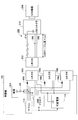
- FIG. 7 is a functional block diagram showing a system to which the in-vehicle device, the USB cable, and the USB device according to the present embodiment are applied.
- USB cable 200 includes a cable length detection resistance line 214 instead of the cable length detection line 204 and the resistance 212.
- the cable length detection resistance wire 214 is a resistance wire used when the in-vehicle device 100 detects the cable length of the USB cable 200.
- the cable length detection resistance wire 214 has a resistance value corresponding to the length of the cable length detection resistance wire 214.
- the cable length detection resistance wire 214 is preferably made of a material (material) whose resistance value varies depending on the length of the cable length detection resistance wire 204. By configuring the cable length detection resistance wire 214 with a material whose resistance value varies depending on the length, the length of the cable length detection resistance wire 214 is determined by the voltage applied to the cable length detection resistance wire 214 by the power source 104. Can be detected.
- the in-vehicle device 100 When the USB cable 200 is connected to the in-vehicle device 100, a voltage is applied to the resistor 106 and the cable length detection resistance wire 214 by the power source 104.
- the microcomputer 110 detects the length of the USB cable 200 by detecting the voltage applied to the cable length detection resistance line 214.
- the in-vehicle device 100 can be used without incorporating a resistor in the USB connector 210. Can detect the cable length.
- step S504 the in-vehicle device 100 detects the cable length of the USB cable 200 connected to the in-vehicle device 100.
- the power source 104 applies power to the resistor 106 and the cable length detection resistor line 214.
- the A / D 1102 converts the voltage value on the anode side of the diode 108 into a digital value.
- the cable length of the USB cable 200 corresponding to the voltage value is acquired by the USB cable length determination unit 114.
- the power supply line 208 is supplied as necessary so as to compensate for the voltage drop in the USB cable.
- the power supply voltage can be controlled. Since the power supply voltage can be controlled so as to compensate for the voltage drop in the USB cable, the communication quality between the in-vehicle device 100 and the USB device 300 can be improved.
- the attenuation of the transmission signal in the communication line 206 of the USB cable is compensated.
- the amplification factor of the transmission signal can be controlled. Since the amplification factor of the transmission signal can be controlled so as to compensate for the attenuation of the transmission signal in the communication line of the USB cable, the communication quality between the in-vehicle device 100 and the USB device 300 can be improved.
- the cable length can be made variable. Then, the in-vehicle device 100 can recognize the cable length.
- the cable length is detected based on the resistance value of the cable length detection resistance line 214, it is not necessary to incorporate a resistor in the USB connector 210.
- FIG. 8 is a functional block diagram showing a system to which an in-vehicle device, a USB cable, and a USB device according to this modification are applied.
- This system has an in-vehicle device 100, a USB cable 200, and a USB device 300.
- the in-vehicle device 100 differs from the in-vehicle device described in the second embodiment in that it includes a plurality of connectors.
- FIG. 8 shows three connectors 102 1 , 102 2 , and 102 3 as an example.
- the number of connectors may be two, or four or more.
- FIG. 8 shows one USB cable 200, but it may be two or three.
- the number of USB cables 200 equal to or less than the number of connectors of the in-vehicle device 100 can be used.
- a USB device 300 is connected to each USB cable 200.
- This USB cable 200 is different from the USB cable 200 shown in the modified example of the first embodiment in that a cable length detection resistance line 214 is provided instead of the cable length detection line 204 and the resistance 212.
- the cable length detection resistance wire 214 is a resistance wire used when the in-vehicle device 100 detects the cable length of the USB cable 200.
- the cable length detection resistance wire 214 has a resistance value corresponding to the length of the cable length detection resistance wire 214.
- the cable length detection resistance wire 214 is preferably made of a material (material) whose resistance value varies depending on the length of the cable length detection resistance wire 214. By configuring the cable length detection resistance wire 214 with a material whose resistance value varies depending on the length, the length of the cable length detection resistance wire 214 is determined by the voltage applied to the cable length detection resistance wire 214 by the power source 104. Can be detected.
- the microcomputer 110 detects the length of the USB cable 200 by detecting the voltage applied to the cable length detection resistance line 214.
- the cable length can be detected in the in-vehicle device 100 without incorporating a resistor in the USB connector 210.
- data can be transferred to / from a plurality of USB devices 300.
- the voltage drop in the plurality of USB cables is compensated.
- the power supply voltage supplied to the power supply line 208 can be controlled as necessary. Since the power supply voltage can be controlled so as to compensate for the voltage drop in the plurality of USB cables, the communication quality between the in-vehicle device 100 and the USB device 300 can be improved.
- the transmission signals of the communication lines 206 of the plurality of USB cables are transmitted.
- the amplification factor of the transmission signal can be controlled as necessary to compensate for the attenuation. Since the amplification factor of the transmission signal can be controlled so as to compensate the attenuation of the transmission signal in the communication lines 206 of the plurality of USB cables, the communication quality between the in-vehicle device 100 and the USB device 300 can be improved.
- the cable length can be made variable. Then, the in-vehicle device 100 can recognize the cable length.
- FIG. 9 is a functional block diagram illustrating a system to which the in-vehicle device, the USB cable, and the USB device according to the present embodiment are applied.
- This system differs from the system described in the first and second embodiments in the configurations of the in-vehicle device 100 and the USB cable 200.
- the cable length of the USB cable 200 connected to the in-vehicle device 100 is limited to a preset length.
- the cable length setting of the USB cable 200 can be changed. Since the cable length of the USB cable 200 can be set, a line for detecting the cable length of the USB cable 200 can be eliminated.
- the in-vehicle device 100 differs from the in-vehicle device described in the first embodiment in that it includes a cable length setting unit 116 instead of the power source 104, the resistor 106, and the diode 108.
- the cable length setting unit 116 is connected to the microcomputer 106 and sets the cable length of the USB cable 200 to be connected to the in-vehicle device 100. It may be set by the user.
- the microcomputer 106 inputs the cable length set by the cable length setting unit 116 to the USB driver 108 and the variable power supply 110. Since the processing by the USB driver 108 and the variable power source 110 is the same as that in the above-described embodiment, the description thereof is omitted.
- FIG. 10 shows the operation of this system.
- the in-vehicle device 100 and the USB cable 200 are connected (step S1002).
- the connector 102 of the in-vehicle device 100 and the connector 202 of the USB cable 200 are connected.
- the in-vehicle device 100 controls the amplification factor of the signal transmitted through the communication line 206 based on the cable length of the USB cable set in the in-vehicle device 100 (step S1004).
- the microcomputer 110 inputs the cable length set by the cable length setting unit 116 to the USB driver 112 and the variable power source 114.
- the USB driver 112 adds the length of the USB cable that connects the connector 102 to the USB driver 112 and / or the variable power source 114 based on the cable length of the USB cable input by the microcomputer 110. Ask. Then, the attenuation amount of the transmission signal is estimated based on the total value of the cable length.
- the USB driver 112 obtains an amplification factor necessary for correcting the attenuation amount.
- the USB driver 112 controls the amplification factor of the signal transmitted through the communication line 206 as necessary according to the amplification factor.
- the in-vehicle device 100 controls the power supply voltage supplied from the power line 208 based on the cable length of the USB cable set in the in-vehicle device 100 (step S1006).
- the variable power supply 114 has a cable length including the length of the USB cable connecting the connector 102 and the USB driver 112 and / or the variable power supply 114 based on the cable length of the USB cable input by the microcomputer 110. Ask. Then, the voltage drop is estimated based on the total value of the cable length.
- the variable power source 114 obtains a voltage value necessary to compensate for the voltage drop.
- the variable power supply 114 controls the power supply voltage supplied by the power supply line 208 in accordance with the voltage value.
- step S1006 a power supply voltage is supplied from the in-vehicle device 100 to the USB device 300, and data is transmitted and received between the in-vehicle device 100 and the USB device 300.
- step S1004 and the process of step S1006 may be reversed or may be performed simultaneously.
- the USB driver 112 may set the amplification factor with reference to a table indicating the correspondence between the cable length and the amplification factor.
- variable power supply 114 may set the power supply voltage with reference to a table indicating the correspondence between the cable length and the voltage value.
- USB cable length of the USB cable 200 may be set for each manufacturer. It is also assumed that the transmission characteristics of the USB cable vary depending on the material of the USB cable. The cable length of the USB cable 200 may be set for each material.
- the power supply line 208 is supplied as necessary so as to compensate for the voltage drop in the USB cable.
- the power supply voltage can be controlled. Since the power supply voltage can be controlled so as to compensate for the voltage drop in the USB cable, the communication quality between the in-vehicle device 100 and the USB device 300 can be improved.
- the attenuation of the transmission signal in the communication line 206 of the USB cable is compensated.
- the amplification factor of the transmission signal can be controlled. Since the amplification factor of the transmission signal can be controlled so as to compensate the attenuation of the transmission signal in the communication line 206 of the USB cable, the communication quality between the in-vehicle device 100 and the USB device 300 can be improved.
- the cable length of the USB cable since the cable length of the USB cable is set, it is not necessary to provide the cable length detection line 204 or the cable length detection resistance line 214 on the USB cable. Since there is no need to provide the cable length detection line 204 or the cable length detection resistance line 214 on the USB cable, the conventional USB cable can be used.
- FIG. 11 is a functional block diagram illustrating a system to which an in-vehicle device, a USB cable, and a USB device according to the present modification are applied.
- This system has an in-vehicle device 100, a USB cable 200, and a USB device 300.
- the in-vehicle device 100 differs from the in-vehicle device described in the third embodiment in that it includes a plurality of connectors.
- FIG. 11 shows three connectors 102 1 , 102 2 , and 102 3 as an example.
- the number of connectors may be two, or four or more.
- FIG. 11 shows one USB cable 200, but it may be two or three.
- the number of USB cables 200 equal to or less than the number of connectors of the in-vehicle device 100 can be used.
- a USB device 300 is connected to each USB cable 200.
- the in-vehicle device 100 is different from the in-vehicle device described in the modification of the first embodiment in that it includes a cable length setting unit 116 instead of the power source 104, the resistor 106, and the diode 108.
- the cable length setting unit 116 is connected to the microcomputer 110 and sets the cable length of the USB cable 200 to be connected to the in-vehicle device 100 for each connector 102. For each connector 102, the microcomputer 110 inputs the cable length set by the cable length setting unit 116 to the USB driver 112 and the variable power source 114. Since the processing by the USB driver 112 and the variable power source 114 is the same as that of the third embodiment described above, description thereof is omitted.
- data can be transferred to / from a plurality of USB devices 300.
- the voltage drop in the plurality of USB cables is compensated.
- the power supply voltage supplied to the power supply line 208 can be controlled as necessary. Since the power supply voltage can be controlled so as to compensate for the voltage drop in the plurality of USB cables, the communication quality between the in-vehicle device 100 and the USB device 300 can be improved.
- the transmission signals of the communication lines 206 of the plurality of USB cables are transmitted.
- the amplification factor of the transmission signal can be controlled as necessary to compensate for the attenuation. Since the amplification factor of the transmission signal can be controlled so as to compensate the attenuation of the transmission signal in the communication lines of the plurality of USB cables, the communication quality between the in-vehicle device 100 and the USB device 300 can be improved.
- the cable length of the USB cable is set, it is not necessary to provide the cable length detection line 204 or the cable length detection resistance line 214 on the USB cable. Since there is no need to provide the cable length detection line 204 or the cable length detection resistance line 214 on the USB cable, the conventional USB cable can be used.
- a control device that controls communication between the in-vehicle device and a device connected to the in-vehicle device via a cable.
- the control device includes a cable length detection unit as a cable length determination unit 1104 that detects the length of the cable, and the on-vehicle device and the device based on the cable length detected by the cable length detection unit.
- a USB driver 112 that performs control for ensuring communication quality between the communication device and a communication control unit as the variable power source 114.
- the in-vehicle device 100 equipped with the control device can detect the cable length of the cable 200.
- the communication control unit can compensate for a voltage drop of the power supply voltage supplied to the power line of the cable and / or compensate for attenuation of a signal transmitted through the signal line of the cable.
- the communication control unit changes the power supply voltage supplied to the power line of the cable based on the length of the cable detected by the cable length detection unit, so that the power supply in the connector connected to the device
- a power supply voltage control unit is provided as the variable power supply 114 that controls the voltage.
- the communication control unit is a connector connected to the device by changing the amplification factor of the signal supplied to the communication line of the cable based on the cable length detected by the cable length detection unit.
- the power supply voltage control unit when the length of the cable detected by the cable length detection unit plus the length of the cable inside the control device exceeds a predetermined length satisfying the standard, the power supply voltage at the connector connected to the device is controlled.
- the power supply voltage can be controlled as necessary.
- the amplification factor control unit when the length of the cable detected by the cable length detection unit plus the length of the cable inside the control device exceeds a predetermined length satisfying the standard
- the amplitude of the connector connected to the device is controlled by changing the amplification factor of the signal supplied to the communication line of the cable.
- the communication line of the cable By changing the amplification factor of the supplied signal, the amplification factor can be controlled as necessary.
- the cable has a detection line for detecting the length of the cable, and a resistor having a resistance value corresponding to the length of the cable connected to the detection line and grounded at the other end.
- the control device includes a power source that applies a voltage to the resistor, a second resistor that is connected to the power source and has the other end connected to the detection line, and a voltage that is applied by the power source.
- a voltage measuring unit configured to measure a voltage applied to the resistor; and a table indicating a correspondence between a value of the voltage applied to the resistor and a length of the cable.
- the cable length detecting unit detects the length of the cable by referring to the table and obtaining the length of the cable corresponding to the voltage applied to the resistor measured by the voltage measuring unit.
- the length of the cable can be detected by obtaining the length of the cable corresponding to the voltage applied to the resistance measured by the voltage measuring unit.
- the cable has a detection line for detecting the length of the cable, and the detection line has a resistance value corresponding to the length of the cable.
- the control device applies a voltage to the detection line, a second resistor connected to the power supply, the other end connected to the detection line, and the power supply.
- a voltage measuring unit for measuring a voltage applied to the detection line, and a table indicating a correspondence between the value of the voltage applied to the detection line and the length of the cable.
- the cable length detecting unit detects the length of the cable by referring to the table and obtaining the length of the cable corresponding to the voltage applied to the detection line measured by the voltage measuring unit.
- the length of the cable can be detected by obtaining the length of the cable corresponding to the voltage applied to the detection line measured by the voltage measuring unit.
- a control device that controls communication between the in-vehicle device and a device connected to the in-vehicle device via a cable.
- the control device ensures the communication quality between the in-vehicle device and the device based on the cable length setting unit for setting the cable length and the length of the USB cable set by the cable length setting unit.
- a communication control unit that performs control for the purpose.
- the cable length setting unit By having the cable length setting unit, the cable length of the cable 200 can be set in the in-vehicle device 100 on which the control device is mounted.
- the communication control unit By having the communication control unit, it is possible to ensure communication quality between the mounting machine 100 and the device.
- the communication control unit can compensate for a voltage drop of the power supply voltage supplied to the power line of the cable and / or compensate for attenuation of a signal transmitted through the signal line of the cable.
- the communication control unit changes the power supply voltage supplied to the power supply line of the cable based on the cable length set by the cable length setting unit, whereby the power supply in the connector connected to the device A power supply voltage control unit for controlling the voltage is included.
- the communication control unit is a connector connected to the device by changing the amplification factor of the signal supplied to the communication line of the cable based on the cable length set by the cable length setting unit.
- An amplification factor control unit for controlling the amplitude of the.
- an in-vehicle device having the control device described above is provided.
- a system including an in-vehicle device and a cable connected to the in-vehicle device and connected to the device at the other end.
- the cable includes a detection line for detecting the length of the cable, and a resistor having a resistance value corresponding to the length of the cable connected to the detection line and grounded at the other end.
- the in-vehicle device includes a power source that applies a voltage to the resistor, a second resistor that is connected to the power source and the other end is connected to the detection line, and the resistor when the voltage is applied by the power source.
- a voltage measuring unit for measuring a voltage applied to the resistor, a table indicating a correspondence between a value of the voltage applied to the resistor and a cable length, a cable length detecting unit for detecting a cable length, and the cable And a communication control unit that performs control for ensuring communication quality between the in-vehicle device and the device based on the length of the cable detected by the length detection unit.
- the cable length detecting unit detects the length of the cable by referring to the table and obtaining the length of the cable corresponding to the voltage applied to the resistor measured by the voltage measuring unit.
- the length of the cable can be detected by obtaining the length of the cable corresponding to the voltage applied to the resistor measured by the voltage measuring unit.
- the communication control unit can compensate for a voltage drop of the power supply voltage supplied to the power line of the cable and / or compensate for attenuation of a signal transmitted through the signal line of the cable.
- a system including an in-vehicle device and a cable connected to the in-vehicle device and connected to the device at the other end.
- the cable has a detection line for detecting the length of the cable, and the detection line has a resistance value corresponding to the length of the cable.
- the vehicle-mounted device has a power source that applies a voltage to the detection line, a second resistor that is connected to the power source and has the other end connected to the detection line, and when the voltage is applied by the power source, A voltage measuring unit for measuring a voltage applied to the detection line; a table indicating a correspondence between a value of the voltage applied to the detection line and a cable length; and a cable length detection unit for detecting the cable length; And a communication control unit that performs control for ensuring communication quality between the in-vehicle device and the device based on the length of the cable detected by the cable length detection unit.
- the cable length detecting unit detects the length of the cable by referring to the table and obtaining the length of the cable corresponding to the voltage applied to the detection line measured by the voltage measuring unit.
- the length of the cable can be detected by obtaining the length of the cable corresponding to the voltage applied to the detection line measured by the voltage measuring unit.
- the communication control unit can compensate for a voltage drop of the power supply voltage supplied to the power line of the cable and / or compensate for attenuation of a signal transmitted through the signal line of the cable.
Abstract
Provided is a controller which controls communication between an in-vehicle device and a device connected to the in-vehicle device through a cable. The controller has a cable length detecting section which detects the length of the cable, and a communication control section which performs control so as to ensure communication qualities between the in-vehicle device and the device.
Description
本発明は、車載機、該車載機に例えばUSBを介して接続される各種機器との間の通信を制御する制御装置、及び該車載機を含むシステムに関する。
The present invention relates to an in-vehicle device, a control device that controls communication with various devices connected to the in-vehicle device via, for example, USB, and a system including the in-vehicle device.
車載機に、USB(Universal Serial Bus)を介して、各種の機器(以下、USB機器と呼ぶ)を接続することが行われている。車載機にはカーオーディオやカーナビゲーションなどが含まれ、USB機器にはハードディスク(HD: hard disk)や音楽プレイヤー、センサなどが含まれる。
Various devices (hereinafter referred to as USB devices) are connected to in-vehicle devices via USB (Universal Serial Bus). In-vehicle devices include car audio and car navigation, and USB devices include hard disks (HD), music players, and sensors.
例えば、車載機は、USB制御ユニット(USB制御装置)を有する。USB制御ユニットはUSBコネクタと接続される。USBケーブルを介して、車載機の有するコネクタとUSB機器の有するUSBコネクタとが接続されることにより、車載機とUSB機器とが接続される。USBケーブルは、電源線、通信線、及びアース線を含む。
For example, the in-vehicle device has a USB control unit (USB control device). The USB control unit is connected to the USB connector. By connecting the connector of the in-vehicle device and the USB connector of the USB device via the USB cable, the in-vehicle device and the USB device are connected. The USB cable includes a power line, a communication line, and a ground line.
USB制御ユニットには、USB機器に電源を供給する電源線が接続される。USB制御ユニットは、USBコネクタ及び電源線を介して、当該車載機と接続されたUSB機器に、+5V(最大電流容量0.5A)の電源を供給する。
The USB control unit is connected to a power line that supplies power to the USB device. The USB control unit supplies power of +5 V (maximum current capacity 0.5 A) to the USB device connected to the in-vehicle device via the USB connector and the power line.
USB機器は、USB制御ユニットから供給される電源により動作する。USB機器の動作保証電圧範囲は、規格に従う。一般的には、DC+5V±5%である。該規格には、USB2.0が含まれる。
USB devices operate with power supplied from the USB control unit. The guaranteed operating voltage range for USB devices follows the standard. Generally, it is DC + 5V ± 5%. The standard includes USB 2.0.
USB制御ユニットとUSB機器との間をUSBケーブルにより接続する場合、該USBケーブルにおいて電圧降下が生じる。該USBケーブルの長さが長くなる場合には、該電圧降下により、電源ケーブルを介してUSB機器に供給される電源電圧が規格に規定されている許容値未満に低下することもある。USB機器に供給される電源電圧が低下することにより、USB機器が動作しなくなる場合がある。換言すれば、USBケーブル長に比例する線路抵抗により消費される電力により、USB制御ユニットの電源からの電源電圧が電圧降下し、USB機器の動作保証電圧+5V±5%を満たさない場合がある。
When connecting the USB control unit and the USB device with a USB cable, a voltage drop occurs in the USB cable. When the length of the USB cable is increased, the voltage drop may cause the power supply voltage supplied to the USB device via the power cable to drop below an allowable value defined in the standard. When the power supply voltage supplied to the USB device decreases, the USB device may not operate. In other words, the power consumed by the line resistance proportional to the USB cable length may cause the power supply voltage from the power supply of the USB control unit to drop, and the USB device operation guarantee voltage + 5V ± 5% may not be satisfied.
USB制御ユニットとUSB機器との間の最大伝送距離は、規格により規定されている。例えば、USB2.0では、最大伝送距離は5mである。最大伝送距離はUSB制御ユニットとUSB機器との間を接続するUSBケーブルの長さに相当するため、該長さを超えないように、USB制御ユニットとUSB機器とを配置する必要がある。
The maximum transmission distance between the USB control unit and the USB device is defined by the standard. For example, in USB 2.0, the maximum transmission distance is 5 m. Since the maximum transmission distance corresponds to the length of the USB cable connecting the USB control unit and the USB device, it is necessary to arrange the USB control unit and the USB device so as not to exceed the length.
しかし、車載機が搭載される車内の環境によっては、USB制御ユニットとUSB機器とを近接して配置できない場合がある。USB制御ユニットとUSB機器との間が最大伝送距離を超えることも想定される。USB制御ユニットとUSB機器との間が最大伝送距離を超える場合には、信号ケーブルにより送信される信号が減衰し、規格に規定される許容値未満の振幅となることもある。
However, depending on the environment in which the in-vehicle device is installed, the USB control unit and the USB device may not be placed close to each other. It is also assumed that the maximum transmission distance is exceeded between the USB control unit and the USB device. If the distance between the USB control unit and the USB device exceeds the maximum transmission distance, the signal transmitted by the signal cable is attenuated, and the amplitude may be less than the allowable value specified in the standard.
USB制御ユニットとUSB機器との間の距離が最大伝送距離を超える場合に、該USB制御ユニットとUSB機器との間に、リピータと呼ばれる増幅装置を設置したり、昇圧器を設置したりすることも行われている。該リピータにより信号の減衰が補償され、昇圧器により電圧降下が補償される。しかし、リピータ及び/又は昇圧器を設置することが困難である場合もある。
When the distance between the USB control unit and the USB device exceeds the maximum transmission distance, an amplifying device called a repeater or a booster must be installed between the USB control unit and the USB device. Has also been done. The repeater compensates for signal attenuation, and the booster compensates for voltage drop. However, it may be difficult to install repeaters and / or boosters.
本発明は、上述の点に鑑みてなされたものであり、制御ユニットと機器との間が最大伝送距離を超える場合においても、リピータ及び/又は昇圧器を必要とせずに、制御ユニットと機器との間の通信品質を確保できる制御装置、車載機及びシステム並びに方法を提供することを目的とする。
The present invention has been made in view of the above points, and even when the distance between the control unit and the device exceeds the maximum transmission distance, the repeater and / or the booster are not required, and the control unit and the device It is an object of the present invention to provide a control device, an in-vehicle device, a system, and a method that can ensure communication quality between the devices.
本制御装置は、
車載機と、該車載機にケーブルを介して接続される機器との間の通信を制御する制御装置であって、
ケーブルの長さを検出するケーブル長検出部と、
該ケーブル長検出部により検出されたケーブルの長さに基づいて、前記車載機と前記機器との間の通信品質を確保するための制御を行う通信制御部と
を有する。 This control device
A control device that controls communication between an in-vehicle device and a device connected to the in-vehicle device via a cable,
A cable length detector for detecting the length of the cable;
A communication control unit that performs control for ensuring communication quality between the in-vehicle device and the device based on the length of the cable detected by the cable length detection unit.
本制御装置は、
車載機と、該車載機にケーブルを介して接続される機器との間の通信を制御する制御装置であって、
ケーブルの長さを設定するケーブル長設定部と、
該ケーブル長設定部により設定されたケーブルの長さに基づいて、前記車載機と前記機器との間の通信品質を確保するための制御を行う通信制御部と
を有する。 This control device
A control device that controls communication between an in-vehicle device and a device connected to the in-vehicle device via a cable,
A cable length setting section for setting the cable length;
A communication control unit that performs control for ensuring communication quality between the in-vehicle device and the device based on the cable length set by the cable length setting unit.
本車載機は、上記制御装置を有する。
This in-vehicle device has the above control device.
本システムは、
車載機と、該車載機に接続され他端が機器と接続されるケーブルとを有するシステムであって、
前記ケーブルは、
該ケーブルの長さを検出するための検知線と、
該検知線と接続され他端が接地された該ケーブルの長さに対応した抵抗値を有する抵抗と
を有し、
前記車載機は、
前記抵抗に電圧を印加する電源と、
該電源に接続され、他端が前記検知線に接続される第2の抵抗と、
前記電源により電圧が印加された場合に、前記抵抗に印加される電圧を測定する電圧測定部と、
前記抵抗に印加される電圧の値と、ケーブルの長さとの対応を示すテーブルと、
ケーブルの長さを検出するケーブル長検出部と、
該ケーブル長検出部により検出されたケーブルの長さに基づいて、前記車載機と前記機器との間の通信品質を確保するための制御を行う通信制御部と
を有し、
前記ケーブル長検出部は、前記テーブルを参照し、前記電圧測定部により測定された前記抵抗に印加される電圧に対応するケーブルの長さを求めることにより、ケーブルの長さを検出する。 This system
A system having an in-vehicle device and a cable connected to the in-vehicle device and connected to the other end of the device,
The cable is
A detection line for detecting the length of the cable;
A resistor having a resistance value corresponding to the length of the cable connected to the detection line and grounded at the other end;
The in-vehicle device is
A power supply for applying a voltage to the resistor;
A second resistor connected to the power source and having the other end connected to the detection line;
A voltage measuring unit that measures a voltage applied to the resistor when a voltage is applied by the power source; and
A table showing the correspondence between the value of the voltage applied to the resistor and the length of the cable;
A cable length detector for detecting the length of the cable;
A communication control unit that performs control to ensure communication quality between the in-vehicle device and the device based on the length of the cable detected by the cable length detection unit;
The cable length detecting unit detects the length of the cable by referring to the table and obtaining the length of the cable corresponding to the voltage applied to the resistor measured by the voltage measuring unit.
本システムは、
車載機と、該車載機に接続され他端が機器と接続されるケーブルとを有するシステムであって、
前記ケーブルは、
該ケーブルの長さを検出するための検知線
を有し、
該検知線は、該ケーブルの長さに対応した抵抗値を有し、
前記車載機は、
前記検知線に電圧を印加する電源と、
該電源に接続され、他端が前記検知線に接続される第2の抵抗と、
前記電源により電圧が印加された場合に、前記検知線に印加される電圧を測定する電圧測定部と、
前記検知線に印加される電圧の値と、ケーブルの長さとの対応を示すテーブルと、
ケーブルの長さを検出するケーブル長検出部と、
該ケーブル長検出部により検出されたケーブルの長さに基づいて、前記車載機と前記機器との間の通信品質を確保するための制御を行う通信制御部と
を有し、
前記ケーブル長検出部は、前記テーブルを参照し、前記電圧測定部により測定された前記検知線に印加される電圧に対応するケーブルの長さを求めることにより、ケーブルの長さを検出する。 This system
A system having an in-vehicle device and a cable connected to the in-vehicle device and connected to the other end of the device,
The cable is
A detection line for detecting the length of the cable,
The detection line has a resistance value corresponding to the length of the cable,
The in-vehicle device is
A power source for applying a voltage to the detection line;
A second resistor connected to the power source and having the other end connected to the detection line;
A voltage measuring unit for measuring a voltage applied to the detection line when a voltage is applied by the power source; and
A table showing the correspondence between the value of the voltage applied to the detection line and the length of the cable;
A cable length detector for detecting the length of the cable;
A communication control unit that performs control to ensure communication quality between the in-vehicle device and the device based on the length of the cable detected by the cable length detection unit;
The cable length detecting unit detects the length of the cable by referring to the table and obtaining the length of the cable corresponding to the voltage applied to the detection line measured by the voltage measuring unit.
本方法は、
車載機と、該車載機にケーブルを介して接続される機器との間の通信を制御する制御装置における方法であって、
ケーブルの長さを検出するケーブル長検出ステップと、
該ケーブル長検出ステップにより検出されたケーブルの長さに基づいて、前記車載機と前記機器との間の通信品質を確保するための制御を行う通信制御ステップと
を有する。 This method
A method in a control device for controlling communication between an in-vehicle device and a device connected to the in-vehicle device via a cable,
A cable length detection step for detecting the length of the cable;
A communication control step for performing control for ensuring communication quality between the in-vehicle device and the device based on the length of the cable detected by the cable length detection step.
本方法は、
車載機と、該車載機にケーブルを介して接続される機器との間の通信を制御する制御装置における方法であって、
ケーブルの長さを設定するケーブル長設定ステップと、
該ケーブル長設定ステップにより設定されたケーブルの長さに基づいて、前記車載機と前記機器との間の通信品質を確保するための制御を行う通信制御ステップと
を有する。 This method
A method in a control device for controlling communication between an in-vehicle device and a device connected to the in-vehicle device via a cable,
A cable length setting step for setting the cable length;
A communication control step for performing control for ensuring communication quality between the in-vehicle device and the device based on the cable length set in the cable length setting step.
開示の制御装置、車載機及びシステム並びに方法によれば、制御ユニットと機器との間が最大伝送距離を超える場合においても、リピータ及び/又は昇圧器を必要とせずに、制御ユニットと機器との間の通信品質を確保できる。
According to the disclosed control device, in-vehicle device, system, and method, even when the maximum transmission distance is exceeded between the control unit and the device, the repeater and / or the booster are not required, and the control unit and the device can be connected. Communication quality can be secured.
次に、本発明を実施するための形態を、以下の実施例に基づき図面を参照しつつ説明する。
なお、実施例を説明するための全図において、同一機能を有するものは同一符号を用い、繰り返しの説明は省略する。 Next, the form for implementing this invention is demonstrated, referring drawings based on the following Examples.
In all the drawings for explaining the embodiments, the same reference numerals are used for those having the same function, and repeated explanation is omitted.
<第1の実施例>
<システム>
図1は、本実施例に従った車載機と、USBケーブルと、USB機器とが適用されるシステムを示す機能ブロック図である。本実施例では、一例として、車載機と、該車載機にUSBケーブルを介して接続されるUSB機器との間の通信を制御する場合について説明するが、USBに限られず、車載機と、該車載機にケーブルを介して接続される機器との間の通信を制御する場合に適用できる。 <First embodiment>
<System>
FIG. 1 is a functional block diagram showing a system to which an in-vehicle device, a USB cable, and a USB device according to the present embodiment are applied. In this embodiment, as an example, a case where communication between an in-vehicle device and a USB device connected to the in-vehicle device via a USB cable is controlled will be described. The present invention can be applied when controlling communication with a device connected to a vehicle-mounted device via a cable.
本システムは、車載機100と、USBケーブル200と、USB機器300とを有する。
This system has an in-vehicle device 100, a USB cable 200, and a USB device 300.
車載機100は、USB制御装置を有する。該USB制御装置は、コネクタ102と、電源104と、抵抗106と、ダイオード108と、マイコン110と、USBドライバ112と、可変電源114とを有する。
The in-vehicle device 100 has a USB control device. The USB control device includes a connector 102, a power supply 104, a resistor 106, a diode 108, a microcomputer 110, a USB driver 112, and a variable power supply 114.
USBケーブル200は、コネクタ202と、ケーブル長検知線204と、通信線(D+,D-)206と、電源線(VBUS)208と、USBコネクタ210とを有する。図1において、GND線は省略される。また、ID線が含まれるようにしてもよい。また、USBコネクタ210は、ケーブル長検知線204と接続され、他端が接地されたケーブル長検知用抵抗部品212を有する。
The USB cable 200 includes a connector 202, a cable length detection line 204, a communication line (D +, D-) 206, a power supply line (VBUS) 208, and a USB connector 210. In FIG. 1, the GND line is omitted. Also, an ID line may be included. The USB connector 210 includes a cable length detection resistor component 212 that is connected to the cable length detection line 204 and is grounded at the other end.
USBケーブルの最大の長さは、USB規格により規定されている。例えば、USB2.0では、5mに規定されている。従って、車載機100とUSB機器300との間を接続するUSBケーブル200は5m以下で使用されるべきである。しかし、車両に車載機100が設置される際に、コネクタ102とUSBドライバ112及び/又は可変電源114との間を接続するUSBケーブルが車両に組み込まれる場合がある。コネクタ102とUSBドライバ112及び/又は可変電源114との間を接続するUSBケーブルが車両に組み込まれる場合には、車載機100に接続されるUSBケーブル200の長さが5mであっても、コネクタ102とUSBドライバ112及び/又は可変電源114との間を接続するUSBケーブルの長さの分延長されることになるため、実質的には5mを超える。
The maximum length of the USB cable is defined by the USB standard. For example, USB 2.0 specifies 5m. Therefore, the USB cable 200 for connecting the in-vehicle device 100 and the USB device 300 should be used at 5 m or less. However, when the vehicle-mounted device 100 is installed in the vehicle, a USB cable that connects the connector 102 and the USB driver 112 and / or the variable power source 114 may be incorporated into the vehicle. When a USB cable that connects between the connector 102 and the USB driver 112 and / or the variable power supply 114 is incorporated in a vehicle, the connector is used even if the length of the USB cable 200 connected to the in-vehicle device 100 is 5 m. Since the length of the USB cable connecting between the terminal 102 and the USB driver 112 and / or the variable power source 114 is extended, the length substantially exceeds 5 m.
本システムでは、車載機100は、USBケーブルの長さを検出する。該USBケーブルの長さは、コネクタ102と接続され、他端がUSB機器300と接続されるUSBケーブル200の長さである。そして、車載機100は、検出したUSBケーブル200の長さに、コネクタ102とUSBドライバ112及び/又は可変電源114との間を接続するUSBケーブルの長さを加え、該合計長に基づいて、車載機100とUSB機器300との間の通信品質を確保するための制御を行う。本実施例では、車載機100とUSB機器300との間の通信品質を確保するための制御として、通信線206により送信される信号の増幅率及び/又は電源線208に供給される電源電圧を制御する例について説明する。しかし、通信線206により送信される信号の増幅率及び/又は電源線208に供給される電源電圧に限られず、車載機100とUSB機器300との間の通信品質を確保するために制御できるあらゆるパラメータの制御が可能である。
In this system, the in-vehicle device 100 detects the length of the USB cable. The length of the USB cable is the length of the USB cable 200 connected to the connector 102 and the other end connected to the USB device 300. The in-vehicle device 100 adds the length of the USB cable connecting the connector 102 and the USB driver 112 and / or the variable power source 114 to the detected length of the USB cable 200, and based on the total length, Control is performed to ensure communication quality between the in-vehicle device 100 and the USB device 300. In this embodiment, as control for ensuring the communication quality between the in-vehicle device 100 and the USB device 300, the amplification factor of the signal transmitted through the communication line 206 and / or the power supply voltage supplied to the power supply line 208 are set. An example of control will be described. However, the present invention is not limited to the amplification factor of the signal transmitted through the communication line 206 and / or the power supply voltage supplied to the power supply line 208, and any control that can be performed to ensure the communication quality between the in-vehicle device 100 and the USB device 300. Parameters can be controlled.
<車載機>
車載機100について説明する。 <In-vehicle device>
The in-vehicle device 100 will be described.
車載機100について説明する。 <In-vehicle device>
The in-
コネクタ102は、USBケーブル200が接続される。例えば、コネクタ102は、USB A端子のメス端子であってもよい。該コネクタ102は、5本のピン(PIN)を有する。該ピンには、電源線208に接続されるピンと、通信線206に接続される2本のピンと、ケーブル長検知線204に接続されるピンと、GND(図示なし)に接続されるピンとが含まれる。
The USB cable 200 is connected to the connector 102. For example, the connector 102 may be a female terminal of a USB A terminal. The connector 102 has five pins (PIN). The pins include a pin connected to the power supply line 208, two pins connected to the communication line 206, a pin connected to the cable length detection line 204, and a pin connected to GND (not shown). .
電源104は、電圧を印加する。該電源104は、抵抗106を介して、ダイオード108のアノード側と接続され、該ダイオード108のカソード側は、コネクタ102と接続される。該コネクタ102がUSBケーブル200のコネクタ202と接続された場合、ダイオード108のカソード側とケーブル長検知線204とが接続される。
The power supply 104 applies a voltage. The power source 104 is connected to the anode side of the diode 108 via the resistor 106, and the cathode side of the diode 108 is connected to the connector 102. When the connector 102 is connected to the connector 202 of the USB cable 200, the cathode side of the diode 108 and the cable length detection line 204 are connected.
マイコン110は、ダイオード108のアノード側と接続される。マイコン110は、ダイオード108のアノード側の電圧を測定する。換言すれば、マイコン110は、ケーブル長検知線204と抵抗212に印加される電圧を測定する。そして、マイコン110は、該電圧に基づいて、USBケーブルの長さを判別する。
The microcomputer 110 is connected to the anode side of the diode 108. The microcomputer 110 measures the voltage on the anode side of the diode 108. In other words, the microcomputer 110 measures the voltage applied to the cable length detection line 204 and the resistor 212. Then, the microcomputer 110 determines the length of the USB cable based on the voltage.
図2は、車載機100のマイコン110の一例を示す機能ブロック図である。
FIG. 2 is a functional block diagram showing an example of the microcomputer 110 of the in-vehicle device 100.
マイコン110は、アナログ/デジタル変換器(A/D)1102と、USBケーブル長判別部1104と、記憶部1106とを有する。
The microcomputer 110 includes an analog / digital converter (A / D) 1102, a USB cable length determination unit 1104, and a storage unit 1106.
A/D1102は、ダイオード108のアノード側と接続される。A/D1102は、該ダイオード108のアノード側の電圧値を取得し、デジタル値に変換する。A/D1102は、デジタル値に変換したダイオード108のアノード側の電圧値をUSBケーブル長判別部114に入力する。
A / D 1102 is connected to the anode side of the diode 108. The A / D 1102 acquires the voltage value on the anode side of the diode 108 and converts it into a digital value. The A / D 1102 inputs the voltage value on the anode side of the diode 108 converted into a digital value to the USB cable length determination unit 114.
電源104は、抵抗106を介して電圧を印加する。車載機100とUSBケーブル200とが接続されることにより、ダイオード108のカソード側に、ケーブル長検知線204を介して、一端が接地された抵抗212が接続される。該抵抗212の抵抗値は、USBケーブル200のケーブル長に対応して設定される。車載機100とUSBケーブル200とが接続されると、ダイオード108のアノード側の電位は、抵抗212の抵抗値により変化する。従って、抵抗212の抵抗値とダイオード108のアノード側の電位(電圧値)とが対応付けられたテーブルを用意することにより、ダイオード108のアノード側の電位から抵抗212の抵抗値を求めることができる。抵抗212の抵抗値を求めることができるため、該抵抗212の抵抗値に対応するUSBケーブル200のケーブル長を求めることができる。
The power source 104 applies a voltage via the resistor 106. By connecting the in-vehicle device 100 and the USB cable 200, the resistor 212 having one end grounded is connected to the cathode side of the diode 108 via the cable length detection line 204. The resistance value of the resistor 212 is set corresponding to the cable length of the USB cable 200. When the in-vehicle device 100 and the USB cable 200 are connected, the potential on the anode side of the diode 108 changes depending on the resistance value of the resistor 212. Therefore, by preparing a table in which the resistance value of the resistor 212 is associated with the potential (voltage value) on the anode side of the diode 108, the resistance value of the resistor 212 can be obtained from the potential on the anode side of the diode 108. . Since the resistance value of the resistor 212 can be obtained, the cable length of the USB cable 200 corresponding to the resistance value of the resistor 212 can be obtained.
記憶部116は、ダイオード108のアノード側の電位と抵抗212の抵抗値とが対応付けられたテーブルと、抵抗212の抵抗値とUSBケーブル200のケーブル長とが対応付けられたテーブルとが格納される。両テーブルは1つのテーブルに統合されてもよい。1つのテーブルに統合される場合には、ダイオード108のアノード側の電位とUSBケーブル200のケーブル長とが対応付けられたテーブルが格納される。
The storage unit 116 stores a table in which the anode side potential of the diode 108 and the resistance value of the resistor 212 are associated with each other, and a table in which the resistance value of the resistor 212 and the cable length of the USB cable 200 are associated with each other. The Both tables may be integrated into one table. When integrated into one table, a table in which the anode side potential of the diode 108 and the cable length of the USB cable 200 are associated with each other is stored.
USBケーブル長判別部114は、記憶部116に格納されたテーブルを参照し、A/D1102により入力されたダイオード108のアノード側の電位に対応する抵抗212の抵抗値を求める。そして、USBケーブル長判別部114は、該抵抗212の抵抗値に対応するUSBケーブル200のケーブル長を求める。USBケーブル長判別部114は、USBケーブル200のケーブル長をUSBドライバ112及び可変電源114に入力する。
The USB cable length determination unit 114 refers to the table stored in the storage unit 116 and obtains the resistance value of the resistor 212 corresponding to the anode-side potential of the diode 108 input by the A / D 1102. Then, the USB cable length determination unit 114 obtains the cable length of the USB cable 200 corresponding to the resistance value of the resistor 212. The USB cable length determination unit 114 inputs the cable length of the USB cable 200 to the USB driver 112 and the variable power source 114.
USBドライバ112は、USBケーブル200に供給する信号の増幅率を制御する。USB2.0の規格では、通信モードとして、半二重伝送が適用される。半二重伝送では、双方向通信において、同時に双方からデータを送信したり、受信したりすることができず、時間を区切って片方向からの送信しかできない。
The USB driver 112 controls the amplification factor of the signal supplied to the USB cable 200. In the USB 2.0 standard, half-duplex transmission is applied as a communication mode. In half-duplex transmission, in bidirectional communication, data cannot be transmitted or received from both sides at the same time, and transmission from only one direction can be performed by dividing time.
図3は、車載機100により送信されるデータの信号波形の一例を示す。図3において、実線は補正処理前の波形である。換言すれば、車載機100において増幅率を制御する前の波形である。図3において、破線は補正処理後の波形である。換言すれば、車載機100において増幅率を制御した後の波形である。両波形は、USBコネクタ210において検出される波形である。
FIG. 3 shows an example of a signal waveform of data transmitted by the in-vehicle device 100. In FIG. 3, a solid line is a waveform before correction processing. In other words, the waveform is before the gain is controlled in the in-vehicle device 100. In FIG. 3, the broken line is the waveform after the correction process. In other words, it is a waveform after the amplification factor is controlled in the in-vehicle device 100. Both waveforms are waveforms detected by the USB connector 210.
USBドライバ112は、マイコン110により入力されたUSBケーブル200のケーブル長に基づいて、USBケーブル200の通信線206において発生する送信信号の減衰量を推定する。USBドライバ112は、コネクタ102とUSBドライバ112及び/又は可変電源114との間を接続するUSBケーブルの長さをも含めて、USBケーブル200の通信線206において発生する送信信号の減衰量を推定する。USBドライバ112は、データを送信する際には、該減衰量を補正するために増幅する。ケーブル長と送信信号に対する増幅率とが対応付けられたテーブルが用意されてもよい。USBドライバ112は、当該車載機100に接続されたUSBケーブル200のUSBコネクタ210において規格に規定される振幅となるように増幅する。例えば、USBドライバ112は、実線により示されるように減衰後の波形が推定される場合に、破線により示される波形となるように増幅する。
The USB driver 112 estimates the attenuation amount of the transmission signal generated in the communication line 206 of the USB cable 200 based on the cable length of the USB cable 200 input by the microcomputer 110. The USB driver 112 estimates the attenuation amount of the transmission signal generated in the communication line 206 of the USB cable 200 including the length of the USB cable connecting the connector 102 and the USB driver 112 and / or the variable power supply 114. To do. When transmitting data, the USB driver 112 amplifies the data to correct the attenuation. A table in which the cable length is associated with the amplification factor for the transmission signal may be prepared. The USB driver 112 amplifies the USB connector 210 of the USB cable 200 connected to the in-vehicle device 100 so that the amplitude is stipulated in the standard. For example, when the waveform after attenuation is estimated as indicated by a solid line, the USB driver 112 amplifies the waveform to be indicated by a broken line.
USBケーブル200の材質(材料)によっては、通信線206において送信信号が減衰しても、USBコネクタ210において、規格に規定された振幅を満足する場合がある。USBコネクタ210において規格に規定された振幅を満足すると推定される場合には、USBドライバ112は、該減衰量を補正するための増幅を行わないようにしてもよい。必要に応じて増幅を行うことにより、消費電力を低減できる。
Depending on the material (material) of the USB cable 200, even if the transmission signal attenuates on the communication line 206, the USB connector 210 may satisfy the amplitude defined in the standard. If it is estimated that the USB connector 210 satisfies the amplitude defined in the standard, the USB driver 112 may not perform amplification for correcting the attenuation amount. By performing amplification as necessary, power consumption can be reduced.
可変電源114は、USBケーブル200の電源線208に供給する電圧を制御する。USB2.0の規格では、USB機器300への供給電圧は5.0±0.25Vと規定されている。可変電源114は、電源線208だけでなく、USBコネクタ210、及びコネクタ102とUSBドライバ112及び/又は可変電源114との間を接続するUSBケーブルにおける電圧降下を推定する。可変電源114は、該電圧降下を補正するために電圧値を増加させる。ケーブル長と電源電圧の電圧値とが対応付けられたテーブルが用意されてもよい。可変電源114は、当該車載機100に接続されたUSBケーブル200のUSBコネクタ210において、規格に規定される電圧となるように供給する電圧を増加させる。可変電源114は、DC-DCコンバータなどを用いて昇圧を行うようにしてもよいし、レギュレータ型により昇圧を行うようにしてもよい。電源電圧を可変にできれば、いかなる種類の電源を適用できる。
The variable power source 114 controls the voltage supplied to the power line 208 of the USB cable 200. In the USB 2.0 standard, the supply voltage to the USB device 300 is defined as 5.0 ± 0.25V. The variable power supply 114 estimates not only the power line 208 but also a voltage drop in the USB connector 210 and the USB cable connecting the connector 102 and the USB driver 112 and / or the variable power supply 114. The variable power source 114 increases the voltage value to correct the voltage drop. A table in which the cable length and the voltage value of the power supply voltage are associated may be prepared. The variable power supply 114 increases the voltage to be supplied so as to be a voltage specified by the standard at the USB connector 210 of the USB cable 200 connected to the in-vehicle device 100. The variable power supply 114 may be boosted using a DC-DC converter or the like, or may be boosted by a regulator type. Any type of power supply can be applied as long as the power supply voltage can be varied.
USBケーブル200の材質(材料)によっては、電源線208において電圧降下が生じても、USBコネクタ210において、規格に規定された電圧を満足する場合がある。USBコネクタ210において規格に規定された電圧を満足すると推定される場合には、可変電源114は、該電圧降下を補償するための電圧の増加を行わないようにしてもよい。必要に応じて電源電圧の制御を行うことにより、消費電力を低減できる。
Depending on the material (material) of the USB cable 200, even if a voltage drop occurs in the power line 208, the USB connector 210 may satisfy the voltage specified in the standard. When it is estimated that the voltage specified in the standard in the USB connector 210 is satisfied, the variable power source 114 may not increase the voltage for compensating for the voltage drop. Power consumption can be reduced by controlling the power supply voltage as necessary.
図4は、車載機における電源電圧の設定例を示す。図4において、実線は従来における電圧線に供給される電圧と、該電圧が電圧降下によりUSBコネクタ210において規格を満たさなくなる例を示す。図4において、破線は本実施例における電圧線に供給される電圧と、該電圧が電圧降下により低下してもUSBコネクタ210において規格を満たす例を示す。
FIG. 4 shows an example of setting the power supply voltage in the in-vehicle device. In FIG. 4, a solid line shows a voltage supplied to a conventional voltage line and an example in which the voltage does not satisfy the standard in the USB connector 210 due to a voltage drop. In FIG. 4, a broken line indicates a voltage supplied to the voltage line in the present embodiment and an example that satisfies the standard in the USB connector 210 even when the voltage drops due to a voltage drop.
従来は、図4の実線で示されるように、車載機100において電源ケーブルに供給される電源電圧は5Vに設定される。5Vに設定された電源電圧は電圧降下(図4において、(1)により示す)のため、USBコネクタ210では、USB規格に規定される5.0±0.25Vを満足しない。5.0V-0.25V=4.75V未満に降下する。
Conventionally, as indicated by the solid line in FIG. 4, the power supply voltage supplied to the power cable in the in-vehicle device 100 is set to 5V. Since the power supply voltage set to 5 V is a voltage drop (indicated by (1) in FIG. 4), the USB connector 210 does not satisfy 5.0 ± 0.25 V defined by the USB standard. It drops below 5.0V-0.25V = 4.75V.
一方、図4の破線で示されるように、本実施例では、USBコネクタ210において規格を満足するように、電源線208、及びコネクタ102とUSBドライバ112及び/又は可変電源114との間を接続するUSBケーブルの長さに基づいて電源電圧が制御されるため、電圧降下(図4において、(2)により示す)が生じても、USBコネクタ210ではUSB規格に規定される5.0±0.25Vを満足する。車載機100において供給される電源電圧が5.0+0.25V=5.25Vを超えることもありうる。
On the other hand, as shown by the broken line in FIG. 4, in this embodiment, the USB connector 210 connects the power line 208 and the connector 102 to the USB driver 112 and / or the variable power source 114 so that the standard is satisfied. Since the power supply voltage is controlled based on the length of the USB cable to be used, even if a voltage drop (indicated by (2) in FIG. 4) occurs, the USB connector 210 is set to 5.0 ± 0.25 V defined by the USB standard. Satisfied. The power supply voltage supplied in the in-vehicle device 100 may exceed 5.0 + 0.25V = 5.25V.
<USBケーブル>
USBケーブル200について説明する。 <USB cable>
TheUSB cable 200 will be described.
USBケーブル200について説明する。 <USB cable>
The
コネクタ202は、車載機100が接続される。例えば、コネクタ202は、USB A端子のオス端子であってもよい。該コネクタ202は、コネクタ102に対応して、5本のピン(PIN)を有する。該ピンには、電源線208に接続されるピンと、通信線206に接続される2本のピンと、ケーブル長検知線204に接続されるピンと、GND(図示なし)に接続されるピンとが含まれる。
The connector 202 is connected to the in-vehicle device 100. For example, the connector 202 may be a USB A male terminal. The connector 202 has five pins (PIN) corresponding to the connector 102. The pins include a pin connected to the power supply line 208, two pins connected to the communication line 206, a pin connected to the cable length detection line 204, and a pin connected to GND (not shown). .
ケーブル長検知線204は、車載機100が、当該USBケーブル200のケーブル長を検知する際に使用される電線である。該ケーブル長検知線204のコネクタ202とは反対側の他端には抵抗212が接続される。ケーブル長検知線204は、該ケーブル長検知線204の長さが変化しても、抵抗値の変化が小さい材質であるのが好ましい。長さの変化による抵抗値の変化が小さい材質によりケーブル長検知線204を構成することにより、ケーブル長検知線204に印加される電圧を小さくできる。ケーブル長検知線204に印加される電圧を小さくできるため、抵抗212に印加される電圧の検出誤差を小さくできる。抵抗212に印加される電圧の検出誤差を小さくできるため、該抵抗212に印加される電圧により検出されるケーブル長の検出誤差を小さくできる。USBケーブル200が車載機100に接続されると、電源104により、抵抗106及び抵抗212に対して、電圧が印加される。マイコン110は、抵抗212に印加された電圧を検出することにより、USBケーブル200の長さを検出する。
The cable length detection line 204 is an electric wire used when the in-vehicle device 100 detects the cable length of the USB cable 200. A resistor 212 is connected to the other end of the cable length detection line 204 opposite to the connector 202. The cable length detection line 204 is preferably made of a material whose resistance value is small even when the length of the cable length detection line 204 changes. By configuring the cable length detection line 204 with a material having a small change in resistance value due to a change in length, the voltage applied to the cable length detection line 204 can be reduced. Since the voltage applied to the cable length detection line 204 can be reduced, the detection error of the voltage applied to the resistor 212 can be reduced. Since the detection error of the voltage applied to the resistor 212 can be reduced, the detection error of the cable length detected by the voltage applied to the resistor 212 can be reduced. When the USB cable 200 is connected to the in-vehicle device 100, a voltage is applied to the resistor 106 and the resistor 212 by the power source 104. The microcomputer 110 detects the length of the USB cable 200 by detecting the voltage applied to the resistor 212.
通信線206は、信号の転送に使用される信号送信線である。該通信線206には、差動対(D+)と差動対(D-)が含まれる。
The communication line 206 is a signal transmission line used for signal transfer. The communication line 206 includes a differential pair (D +) and a differential pair (D−).
電源線208は、USB機器300に電源を供給するための電線である。
The power line 208 is an electric wire for supplying power to the USB device 300.
USBコネクタ210は、USB機器300と接続される。USBコネクタ210は、例えば、USB A端子のメス端子であってもよい。該USBコネクタ212は、4本のピン(PIN)を有する。該ピンには、電源線208に接続されるピンと、通信線206に接続される2本のピンと、GND(図示なし)に接続されるピンとが含まれる。
The USB connector 210 is connected to the USB device 300. The USB connector 210 may be, for example, a female terminal of a USB A terminal. The USB connector 212 has four pins (PIN). The pins include a pin connected to the power supply line 208, two pins connected to the communication line 206, and a pin connected to GND (not shown).
抵抗212は、USBケーブル長検知線204の長さに対応する抵抗値を有する抵抗により構成される。該抵抗212は、USBコネクタ210と一体となるように構成される。
The resistor 212 is configured by a resistor having a resistance value corresponding to the length of the USB cable length detection line 204. The resistor 212 is configured to be integrated with the USB connector 210.
USB機器300は、USBで接続される機器であればその種類は問わない。例えば、携帯型デジタル音楽プレイヤー、USBメモリ、USBにより接続されるハードディスク(HD: Hard Disk)が含まれる。
The type of the USB device 300 is not limited as long as it is a device connected by USB. For example, a portable digital music player, a USB memory, and a hard disk (HD: Hard Disk) connected by USB are included.
<本システムの動作>
図5は、本システムの動作を示す。図5では、本車載機100に搭載されたUSB制御装置における動作が主に説明される。 <Operation of this system>
FIG. 5 shows the operation of the system. In FIG. 5, the operation in the USB control device mounted on the in-vehicle device 100 is mainly described.
図5は、本システムの動作を示す。図5では、本車載機100に搭載されたUSB制御装置における動作が主に説明される。 <Operation of this system>
FIG. 5 shows the operation of the system. In FIG. 5, the operation in the USB control device mounted on the in-
車載機100とUSBケーブル200とが接続される(ステップS502)。車載機100のコネクタ102とUSBケーブル200のコネクタ202とが接続される。
The in-vehicle device 100 and the USB cable 200 are connected (step S502). The connector 102 of the in-vehicle device 100 and the connector 202 of the USB cable 200 are connected.
車載機100は、当該車載機100に接続されたUSBケーブル200のケーブル長を検出する(ステップS504)。車載機100にUSBケーブル200が接続されると、電源104は、抵抗106と抵抗212との間に、電圧を印加する。A/D1102は、ダイオード108のアノード側の電圧値をデジタル値に変換する。該電圧値に対応するUSBケーブル200のケーブル長が、USBケーブル長判別部1104において取得される。
The in-vehicle device 100 detects the cable length of the USB cable 200 connected to the in-vehicle device 100 (step S504). When the USB cable 200 is connected to the in-vehicle device 100, the power source 104 applies a voltage between the resistor 106 and the resistor 212. The A / D 1102 converts the voltage value on the anode side of the diode 108 into a digital value. The USB cable length determination unit 1104 acquires the cable length of the USB cable 200 corresponding to the voltage value.
車載機100は、通信線206により送信される信号の増幅率を制御する(ステップS506)。USBドライバ112は、ステップS504により検出されたケーブル長に基づいて、コネクタ102とUSBドライバ112及び/又は可変電源114との間を接続するUSBケーブルの長さをも加えたケーブル長を求める。そして、該ケーブル長の合計長に基づいて、送信信号の減衰量を推定する。USBドライバ112は、該減衰量を補正するために必要な増幅率を求める。USBドライバ112は、該増幅率に従って、必要に応じて通信線206により送信される信号の増幅率を制御する。
The in-vehicle device 100 controls the amplification factor of the signal transmitted through the communication line 206 (step S506). The USB driver 112 obtains the cable length including the length of the USB cable connecting the connector 102 and the USB driver 112 and / or the variable power source 114 based on the cable length detected in step S504. Then, the attenuation amount of the transmission signal is estimated based on the total length of the cable length. The USB driver 112 obtains an amplification factor necessary for correcting the attenuation amount. The USB driver 112 controls the amplification factor of the signal transmitted through the communication line 206 as necessary according to the amplification factor.
車載機100は、電源線208により供給される電源電圧を制御する(ステップS508)。可変電源114は、ステップS504により検出されたケーブル長に基づいて、コネクタ102とUSBドライバ112及び/又は可変電源114との間を接続するUSBケーブルの長さをも加えたケーブル長を求める。そして、該ケーブル長の合計長に基づいて、電圧降下を推定する。可変電源114は、該電圧降下を補償するために必要な電圧値を求める。可変電源114は、該電圧値に従って、電源線208により供給される電源電圧を制御する。
The in-vehicle device 100 controls the power supply voltage supplied through the power supply line 208 (step S508). The variable power source 114 obtains the cable length including the length of the USB cable connecting the connector 102 and the USB driver 112 and / or the variable power source 114 based on the cable length detected in step S504. Then, the voltage drop is estimated based on the total length of the cable length. The variable power source 114 obtains a voltage value necessary to compensate for the voltage drop. The variable power supply 114 controls the power supply voltage supplied by the power supply line 208 in accordance with the voltage value.
ステップS508の後、車載機100からUSB機器300に電源電圧が供給され、車載機100とUSB機器300との間でデータの送受信が行われる。
After step S508, a power supply voltage is supplied from the in-vehicle device 100 to the USB device 300, and data is transmitted and received between the in-vehicle device 100 and the USB device 300.
本動作フローにおいて、ステップS506の処理とステップS508の処理は逆であってもよいし、同時に行われるようにしてもよい。
In this operation flow, the process of step S506 and the process of step S508 may be reversed or may be performed simultaneously.
ステップS506において、USBドライバ112は、ケーブル長と増幅率との対応を示すテーブルを参照して、増幅率を設定するようにしてもよい。
In step S506, the USB driver 112 may set the amplification factor with reference to a table indicating the correspondence between the cable length and the amplification factor.
ステップS508において、可変電源114は、ケーブル長と電圧値との対応を示すテーブルを参照して、電源電圧を設定するようにしてもよい。
In step S508, the variable power supply 114 may set the power supply voltage with reference to a table indicating the correspondence between the cable length and the voltage value.
USBケーブルにおける伝送特性は、該USBケーブルの製造会社により異なることも想定される。例えば、USBケーブルの長さに対応する抵抗212の抵抗値が製造会社により異なることも想定される。抵抗212の抵抗値が製造会社により異なる場合に、製造会社を識別するために、抵抗212を複数の抵抗により構成し、該複数の抵抗の組み合わせにより製造会社を識別するようにしてもよい。例えば、ケーブル長検出用の第1の抵抗と、各製造会社識別用の第2の抵抗とを有するようにしてもよい。第1の抵抗と第2の抵抗とは並列に接続されてもよい。製造会社を識別できるようにした場合、記憶部1106には、製造会社毎に、ダイオード108のアノード側の電位と抵抗212の抵抗値とが対応付けられたテーブルと、抵抗212の抵抗値とUSBケーブル200のケーブル長とが対応付けられたテーブルとが格納される。両テーブルは1つのテーブルに統合されてもよい。1つのテーブルに統合される場合には、ダイオード108のアノード側の電位とUSBケーブル200のケーブル長とが対応付けられたテーブルが格納される。また、USBケーブルにおける伝送特性は、該USBケーブルの材質により異なることも想定される。材質毎に、USBケーブル200のケーブル長が設定されてもよい。
It is assumed that the transmission characteristics of the USB cable will vary depending on the USB cable manufacturer. For example, it is assumed that the resistance value of the resistor 212 corresponding to the length of the USB cable varies depending on the manufacturer. When the resistance value of the resistor 212 differs depending on the manufacturer, the resistor 212 may be configured by a plurality of resistors in order to identify the manufacturer, and the manufacturer may be identified by a combination of the plurality of resistors. For example, you may make it have the 1st resistance for cable length detection, and the 2nd resistance for each manufacturer identification. The first resistor and the second resistor may be connected in parallel. When the manufacturing company can be identified, the storage unit 1106 stores, for each manufacturing company, a table in which the anode-side potential of the diode 108 and the resistance value of the resistor 212 are associated, the resistance value of the resistor 212, and the USB. A table in which the cable length of the cable 200 is associated is stored. Both tables may be integrated into one table. When integrated into one table, a table in which the anode side potential of the diode 108 and the cable length of the USB cable 200 are associated with each other is stored. It is also assumed that the transmission characteristics of the USB cable vary depending on the material of the USB cable. The cable length of the USB cable 200 may be set for each material.
上述した実施例において、電源電圧及び/又は増幅率はマイコン110において設定されるようにしてもよい。
In the embodiment described above, the power supply voltage and / or the amplification factor may be set in the microcomputer 110.
本実施例によれば、USBケーブルの長さが規格により規定される長さを超える場合であっても、該USBケーブルにおける電圧降下を補償するように、必要に応じて電源線208に供給する電源電圧を制御することができる。USBケーブルにおける電圧降下を補償するように電源電圧を制御することができるため、車載機100とUSB機器300との間の通信品質を改善できる。
According to the present embodiment, even when the length of the USB cable exceeds the length specified by the standard, the power supply line 208 is supplied as necessary so as to compensate for the voltage drop in the USB cable. The power supply voltage can be controlled. Since the power supply voltage can be controlled so as to compensate for the voltage drop in the USB cable, the communication quality between the in-vehicle device 100 and the USB device 300 can be improved.
本実施例によれば、USBケーブルの長さが規格により規定される長さを超える場合であっても、該USBケーブルの通信線における送信信号の減衰を補償するように、必要に応じて送信信号の増幅率を制御することができる。USBケーブルの通信線における送信信号の減衰を補償するように送信信号の増幅率を制御することができるため、車載機とUSB機器との間の通信品質を改善できる。
According to this embodiment, even when the length of the USB cable exceeds the length specified by the standard, transmission is performed as necessary so as to compensate for attenuation of the transmission signal in the communication line of the USB cable. The amplification factor of the signal can be controlled. Since the amplification factor of the transmission signal can be controlled so as to compensate the attenuation of the transmission signal in the communication line of the USB cable, the communication quality between the in-vehicle device and the USB device can be improved.
本実施例によれば、ケーブル長検知線204と抵抗212とが対応付けられているため、ケーブル長を可変にできる。そして、車載機100にケーブル長を認識させることができる。
According to the present embodiment, since the cable length detection line 204 and the resistor 212 are associated with each other, the cable length can be made variable. Then, the in-vehicle device 100 can recognize the cable length.
<変形例>
<システム>
図6は、本変形例に従った車載機と、USBケーブルと、USB機器とが適用されるシステムを示す機能ブロック図である。 <Modification>
<System>
FIG. 6 is a functional block diagram showing a system to which an in-vehicle device, a USB cable, and a USB device according to this modification are applied.
<システム>
図6は、本変形例に従った車載機と、USBケーブルと、USB機器とが適用されるシステムを示す機能ブロック図である。 <Modification>
<System>
FIG. 6 is a functional block diagram showing a system to which an in-vehicle device, a USB cable, and a USB device according to this modification are applied.
本システムは、車載機100と、USBケーブル200と、USB機器300とを有する。
This system has an in-vehicle device 100, a USB cable 200, and a USB device 300.
本車載機100は、第1の実施例において説明した車載機と、複数のコネクタを有する点で異なる。図6には、一例として、3個のコネクタ1021、1022、及び1023が示される。コネクタ102の数は2個であってもよいし、4個以上であってもよい。
The in-vehicle device 100 differs from the in-vehicle device described in the first embodiment in that it includes a plurality of connectors. FIG. 6 shows three connectors 102 1 , 102 2 , and 102 3 as an example. The number of connectors 102 may be two, or four or more.
図6には、1本のUSBケーブル200が描かれているが、2本であってもよいし、3本であってもよい。車載機100の有するコネクタ102の数以下のUSBケーブル200を使用できる。該USBケーブル200には、それぞれUSB機器300が接続される。
FIG. 6 shows one USB cable 200, but it may be two or three. The number of USB cables 200 equal to or less than the number of connectors 102 included in the in-vehicle device 100 can be used. A USB device 300 is connected to each USB cable 200.
本車載機100は、複数のコネクタ102を順次切り替えて制御を行う。本車載機100は、コネクタ1021、1022、及び1023それぞれに接続されるUSBケーブル200の通信線206により送信される信号の増幅率及び/又は電源線208に供給される電源電圧を順に制御する。例えば、コネクタ1021に接続されるUSBケーブル200は運転席用、コネクタ1022に接続されるUSBケーブル200は助手席用、コネクタ1023に接続されるUSBケーブル200には後部座席用としてもよい。例えば、運転席用のUSBケーブル200のUSBコネクタ210には運転手の有するUSB機器300が接続され、助手席用のUSBケーブル200のUSBコネクタ210には助手席の人の有するUSB機器300が接続され、後部座席用のUSBケーブル200のUSBコネクタ210には後部座席の人の有するUSB機器300が接続される。
The in-vehicle device 100 performs control by sequentially switching the plurality of connectors 102. The in-vehicle device 100 sequentially determines the amplification factor of the signal transmitted through the communication line 206 of the USB cable 200 connected to each of the connectors 102 1 , 102 2 , and 102 3 and / or the power supply voltage supplied to the power supply line 208. Control. For example, a USB cable 200 connected to connector 102 1 for the driver's seat, a USB cable 200 connected to connector 102 2 passenger, the USB cable 200 connected to connector 102 3 may be a rear seat . For example, the driver's USB device 300 is connected to the USB connector 210 of the driver's USB cable 200, and the USB device 300 of the passenger's seat is connected to the USB connector 210 of the passenger's USB cable 200. The USB device 300 of the person in the rear seat is connected to the USB connector 210 of the USB cable 200 for the rear seat.
車載機100が設置される位置から運転席、助手席、及び後部座席までの距離は、それぞれ異なるため、車載機100のコネクタ1021、1022、及び1023に、それぞれに接続されるUSBケーブル200の長さも異なる。
Since the distances from the position where the in-vehicle device 100 is installed to the driver's seat, the passenger seat, and the rear seat are different, the USB cables connected to the connectors 102 1 , 102 2 , and 102 3 of the in-vehicle device 100, respectively. The length of 200 is also different.
マイコン110は、第1の実施例において説明した方法により、USBケーブル200のケーブル長を順次検出する。マイコン110は、USBケーブル200が接続されたコネクタ102(1021、1022、1023)に接続されたダイオード108(1081、1082、1083)のアノード側の電位を測定することにより、該コネクタに接続されたUSBケーブル200のケーブル長を検出する。車載機100にUSBケーブル200が同時に接続された場合には、所定の順番で順次切り替えて各コネクタ102(1021、1022、1023)に接続されたダイオードのアノード側の電位を測定する。マイコン110は、検出したUSBケーブル200の長さを示す情報をUSBドライバ112及び可変電源114に入力する。
The microcomputer 110 sequentially detects the cable length of the USB cable 200 by the method described in the first embodiment. The microcomputer 110 measures the anode-side potential of the diode 108 (108 1 , 108 2 , 108 3 ) connected to the connector 102 (102 1 , 102 2 , 102 3 ) to which the USB cable 200 is connected. The cable length of the USB cable 200 connected to the connector is detected. When the USB cable 200 is connected to the in-vehicle device 100 at the same time, the potential on the anode side of the diode connected to each connector 102 (102 1 , 102 2 , 102 3 ) is measured sequentially in a predetermined order. The microcomputer 110 inputs information indicating the detected length of the USB cable 200 to the USB driver 112 and the variable power source 114.
USBドライバ112は、所定の順番で順次切り替えて、各コネクタ102(1021、1022、1023)に接続されたUSBケーブル200に供給する信号の増幅率を制御する。
The USB driver 112 sequentially switches in a predetermined order, and controls the amplification factor of the signal supplied to the USB cable 200 connected to each connector 102 (102 1 , 102 2 , 102 3 ).
可変電源114は、所定の順番で順次切り替えて、各コネクタ102(1021、1022、1023)に接続されたUSBケーブル200に供給する電源電圧を制御する。
The variable power supply 114 is sequentially switched in a predetermined order to control the power supply voltage supplied to the USB cable 200 connected to each connector 102 (102 1 , 102 2 , 102 3 ).
本変形例によれば、複数のUSB機器300との間で、通信を行うことができる。
According to this modification, communication can be performed with a plurality of USB devices 300.
本変形例によれば、複数のUSBケーブルの長さが異なり、さらに該長さが規格により規定される長さを超える場合であっても、該複数のUSBケーブルにおける電圧降下を補償するように、必要に応じて電源線208に供給する電源電圧を制御することができる。複数のUSBケーブルにおける電圧降下を補償するように電源電圧を制御することができるため、車載機100とUSB機器300との間の通信品質を改善できる。
According to the present modification, even when the lengths of the plurality of USB cables are different and the length exceeds the length specified by the standard, the voltage drop in the plurality of USB cables is compensated. The power supply voltage supplied to the power supply line 208 can be controlled as necessary. Since the power supply voltage can be controlled so as to compensate for the voltage drop in the plurality of USB cables, the communication quality between the in-vehicle device 100 and the USB device 300 can be improved.
本変形例によれば、複数のUSBケーブルの長さが異なり、さらに該長さが規格により規定される長さを超える場合であっても、該複数のUSBケーブルの通信線における送信信号の減衰を補償するように、必要に応じて送信信号の増幅率を制御することができる。複数のUSBケーブルの通信線における送信信号の減衰を補償するように送信信号の増幅率を制御することができるため、車載機100とUSB機器300との間の通信品質を改善できる。
According to this modification, even when the lengths of the plurality of USB cables are different and the length exceeds the length specified by the standard, the transmission signal is attenuated in the communication lines of the plurality of USB cables. So that the amplification factor of the transmission signal can be controlled as necessary. Since the amplification factor of the transmission signal can be controlled so as to compensate the attenuation of the transmission signal in the communication lines of the plurality of USB cables, the communication quality between the in-vehicle device 100 and the USB device 300 can be improved.
本変形例によれば、ケーブル長検知線204と抵抗212とが対応付けられているため、ケーブル長を可変にできる。そして、車載機100にケーブル長を認識させることができる。
According to this modification, since the cable length detection line 204 and the resistor 212 are associated with each other, the cable length can be made variable. Then, the in-vehicle device 100 can recognize the cable length.
<第2の実施例>
<システム>
図7は、本実施例に従った車載機と、USBケーブルと、USB機器とが適用されるシステムを示す機能ブロック図である。 <Second Embodiment>
<System>
FIG. 7 is a functional block diagram showing a system to which the in-vehicle device, the USB cable, and the USB device according to the present embodiment are applied.
<システム>
図7は、本実施例に従った車載機と、USBケーブルと、USB機器とが適用されるシステムを示す機能ブロック図である。 <Second Embodiment>
<System>
FIG. 7 is a functional block diagram showing a system to which the in-vehicle device, the USB cable, and the USB device according to the present embodiment are applied.
本システムは、第1の実施例において説明したシステムと同様であるが、USBケーブル200が、ケーブル長検知線204及び抵抗212の代わりにケーブル長検知用抵抗線214を有する点が異なる。
This system is the same as the system described in the first embodiment, except that the USB cable 200 includes a cable length detection resistance line 214 instead of the cable length detection line 204 and the resistance 212.
ケーブル長検知用抵抗線214は、車載機100が、当該USBケーブル200のケーブル長を検知する際に使用される抵抗線である。ケーブル長検知用抵抗線214は、該ケーブル長検知用抵抗線214の長さに対応した抵抗値を有する。ケーブル長検知用抵抗線214は、該ケーブル長検知用抵抗線204の長さによって抵抗値が変化する材質(材料)のものであるのが好ましい。長さによって抵抗値が変化する材質によりケーブル長検知用抵抗線214を構成することにより、電源104によりケーブル長検知用抵抗線214に印加される電圧によって、ケーブル長検知用抵抗線214の長さを検出できる。USBケーブル200が車載機100に接続されると、電源104により、抵抗106及びケーブル長検知用抵抗線214に対して、電圧が印加される。マイコン110は、ケーブル長検知用抵抗線214に印加された電圧を検出することにより、USBケーブル200の長さを検出する。ケーブル長検知用抵抗線214の長さに対応した抵抗値を有するケーブル長検知用抵抗線が含まれるUSBケーブル200を用意することにより、USBコネクタ210に抵抗を内蔵することなく、車載機100において、ケーブル長を検出できる。
The cable length detection resistance wire 214 is a resistance wire used when the in-vehicle device 100 detects the cable length of the USB cable 200. The cable length detection resistance wire 214 has a resistance value corresponding to the length of the cable length detection resistance wire 214. The cable length detection resistance wire 214 is preferably made of a material (material) whose resistance value varies depending on the length of the cable length detection resistance wire 204. By configuring the cable length detection resistance wire 214 with a material whose resistance value varies depending on the length, the length of the cable length detection resistance wire 214 is determined by the voltage applied to the cable length detection resistance wire 214 by the power source 104. Can be detected. When the USB cable 200 is connected to the in-vehicle device 100, a voltage is applied to the resistor 106 and the cable length detection resistance wire 214 by the power source 104. The microcomputer 110 detects the length of the USB cable 200 by detecting the voltage applied to the cable length detection resistance line 214. By preparing the USB cable 200 including a cable length detection resistance wire having a resistance value corresponding to the length of the cable length detection resistance wire 214, the in-vehicle device 100 can be used without incorporating a resistor in the USB connector 210. Can detect the cable length.
本車載機100及び本USB機器200は上述した第1の実施例と同様であるので、説明を省略する。
Since the in-vehicle device 100 and the USB device 200 are the same as those in the first embodiment described above, description thereof is omitted.
<本システムの動作>
本システムの動作は、図5に示される動作において、上述した第1の実施例とステップS504の処理が異なる。 <Operation of this system>
The operation of this system is different from the operation of the first embodiment described above in step S504 in the operation shown in FIG.
本システムの動作は、図5に示される動作において、上述した第1の実施例とステップS504の処理が異なる。 <Operation of this system>
The operation of this system is different from the operation of the first embodiment described above in step S504 in the operation shown in FIG.
ステップS504では、車載機100は、当該車載機100に接続されたUSBケーブル200のケーブル長を検出する。車載機100にUSBケーブル200が接続されると、電源104は、抵抗106、及びケーブル長検知用抵抗線214に電源を印加する。A/D1102は、ダイオード108のアノード側の電圧値をデジタル値に変換する。該電圧値に対応するUSBケーブル200のケーブル長が、USBケーブル長判別部114において取得される。
In step S504, the in-vehicle device 100 detects the cable length of the USB cable 200 connected to the in-vehicle device 100. When the USB cable 200 is connected to the in-vehicle device 100, the power source 104 applies power to the resistor 106 and the cable length detection resistor line 214. The A / D 1102 converts the voltage value on the anode side of the diode 108 into a digital value. The cable length of the USB cable 200 corresponding to the voltage value is acquired by the USB cable length determination unit 114.
本実施例によれば、USBケーブルの長さが規格により規定される長さを超える場合であっても、該USBケーブルにおける電圧降下を補償するように、必要に応じて電源線208に供給する電源電圧を制御することができる。USBケーブルにおける電圧降下を補償するように電源電圧を制御することができるため、車載機100とUSB機器300との間の通信品質を改善できる。
According to the present embodiment, even when the length of the USB cable exceeds the length specified by the standard, the power supply line 208 is supplied as necessary so as to compensate for the voltage drop in the USB cable. The power supply voltage can be controlled. Since the power supply voltage can be controlled so as to compensate for the voltage drop in the USB cable, the communication quality between the in-vehicle device 100 and the USB device 300 can be improved.
本実施例によれば、USBケーブルの長さが規格により規定される長さを超える場合であっても、該USBケーブルの通信線206における送信信号の減衰を補償するように、必要に応じて送信信号の増幅率を制御することができる。USBケーブルの通信線における送信信号の減衰を補償するように送信信号の増幅率を制御することができるため、車載機100とUSB機器300との間の通信品質を改善できる。
According to the present embodiment, even if the length of the USB cable exceeds the length specified by the standard, as necessary, the attenuation of the transmission signal in the communication line 206 of the USB cable is compensated. The amplification factor of the transmission signal can be controlled. Since the amplification factor of the transmission signal can be controlled so as to compensate for the attenuation of the transmission signal in the communication line of the USB cable, the communication quality between the in-vehicle device 100 and the USB device 300 can be improved.
本実施例によれば、ケーブル長検知用抵抗線214の抵抗値とケーブル長とが対応付けられているため、ケーブル長を可変にできる。そして、車載機100にケーブル長を認識させることができる。
According to this embodiment, since the resistance value of the cable length detection resistance line 214 and the cable length are associated with each other, the cable length can be made variable. Then, the in-vehicle device 100 can recognize the cable length.
本実施例によれば、ケーブル長検知用抵抗線214の抵抗値により、ケーブル長が検知されるため、USBコネクタ210に抵抗を内蔵する必要がない。
According to this embodiment, since the cable length is detected based on the resistance value of the cable length detection resistance line 214, it is not necessary to incorporate a resistor in the USB connector 210.
<変形例>
<システム>
図8は、本変形例に従った車載機と、USBケーブルと、USB機器とが適用されるシステムを示す機能ブロック図である。 <Modification>
<System>
FIG. 8 is a functional block diagram showing a system to which an in-vehicle device, a USB cable, and a USB device according to this modification are applied.
<システム>
図8は、本変形例に従った車載機と、USBケーブルと、USB機器とが適用されるシステムを示す機能ブロック図である。 <Modification>
<System>
FIG. 8 is a functional block diagram showing a system to which an in-vehicle device, a USB cable, and a USB device according to this modification are applied.
本システムは、車載機100と、USBケーブル200と、USB機器300とを有する。
This system has an in-vehicle device 100, a USB cable 200, and a USB device 300.
本車載機100は、第2の実施例において説明した車載機と、複数のコネクタを有する点で異なる。図8には、一例として、3個のコネクタ1021、1022、及び1023が示される。コネクタの数は2個であってもよいし、4個以上であってもよい。
The in-vehicle device 100 differs from the in-vehicle device described in the second embodiment in that it includes a plurality of connectors. FIG. 8 shows three connectors 102 1 , 102 2 , and 102 3 as an example. The number of connectors may be two, or four or more.
図8には、1本のUSBケーブル200が描かれているが、2本であってもよいし、3本であってもよい。車載機100の有するコネクタの数以下のUSBケーブル200を使用できる。該USBケーブル200には、それぞれUSB機器300が接続される。
FIG. 8 shows one USB cable 200, but it may be two or three. The number of USB cables 200 equal to or less than the number of connectors of the in-vehicle device 100 can be used. A USB device 300 is connected to each USB cable 200.
本USBケーブル200は、第1の実施例の変形例に示したUSBケーブル200と、ケーブル長検知線204及び抵抗212の代わりにケーブル長検知用抵抗線214を有する点が異なる。
This USB cable 200 is different from the USB cable 200 shown in the modified example of the first embodiment in that a cable length detection resistance line 214 is provided instead of the cable length detection line 204 and the resistance 212.
ケーブル長検知用抵抗線214は、車載機100が、当該USBケーブル200のケーブル長を検知する際に使用される抵抗線である。ケーブル長検知用抵抗線214は、該ケーブル長検知用抵抗線214の長さに対応した抵抗値を有する。ケーブル長検知用抵抗線214は、該ケーブル長検知用抵抗線214の長さによって抵抗値が変化する材質(材料)のものであるのが好ましい。長さによって抵抗値が変化する材質によりケーブル長検知用抵抗線214を構成することにより、電源104によりケーブル長検知用抵抗線214に印加される電圧によって、ケーブル長検知用抵抗線214の長さを検出できる。USBケーブル200が車載機100に接続されると、電源104により、抵抗106及びケーブル長検知用抵抗線214に対して、電圧が印加される。マイコン110は、ケーブル長検知用抵抗線214に印加された電圧を検出することにより、USBケーブル200の長さを検出する。
The cable length detection resistance wire 214 is a resistance wire used when the in-vehicle device 100 detects the cable length of the USB cable 200. The cable length detection resistance wire 214 has a resistance value corresponding to the length of the cable length detection resistance wire 214. The cable length detection resistance wire 214 is preferably made of a material (material) whose resistance value varies depending on the length of the cable length detection resistance wire 214. By configuring the cable length detection resistance wire 214 with a material whose resistance value varies depending on the length, the length of the cable length detection resistance wire 214 is determined by the voltage applied to the cable length detection resistance wire 214 by the power source 104. Can be detected. When the USB cable 200 is connected to the in-vehicle device 100, a voltage is applied to the resistor 106 and the cable length detection resistance wire 214 by the power source 104. The microcomputer 110 detects the length of the USB cable 200 by detecting the voltage applied to the cable length detection resistance line 214.
長さに対応した抵抗値を有するケーブル長検知用抵抗線214が含まれるUSBケーブル200を用意することにより、USBコネクタ210に抵抗を内蔵することなく、車載機100において、ケーブル長を検出できる。
By preparing the USB cable 200 including the cable length detection resistance wire 214 having a resistance value corresponding to the length, the cable length can be detected in the in-vehicle device 100 without incorporating a resistor in the USB connector 210.
本車載機100及び本USB機器300は上述した第1の実施例の変形例と同様であるので、説明を省略する。
Since the in-vehicle device 100 and the USB device 300 are the same as the modified example of the first embodiment described above, description thereof is omitted.
本変形例によれば、複数のUSB機器300との間で、データの転送を行うことができる。
According to this modification, data can be transferred to / from a plurality of USB devices 300.
本変形例によれば、複数のUSBケーブルの長さが異なり、さらに該長さが規格により規定される長さを超える場合であっても、該複数のUSBケーブルにおける電圧降下を補償するように、必要に応じて電源線208に供給する電源電圧を制御することができる。複数のUSBケーブルにおける電圧降下を補償するように電源電圧を制御することができるため、車載機100とUSB機器300との間の通信品質を改善できる。
According to the present modification, even when the lengths of the plurality of USB cables are different and the length exceeds the length specified by the standard, the voltage drop in the plurality of USB cables is compensated. The power supply voltage supplied to the power supply line 208 can be controlled as necessary. Since the power supply voltage can be controlled so as to compensate for the voltage drop in the plurality of USB cables, the communication quality between the in-vehicle device 100 and the USB device 300 can be improved.
本変形例によれば、複数のUSBケーブルの長さが異なり、さらに該長さが規格により規定される長さを超える場合であっても、該複数のUSBケーブルの通信線206における送信信号の減衰を補償するように、必要に応じて送信信号の増幅率を制御することができる。複数のUSBケーブルの通信線206における送信信号の減衰を補償するように送信信号の増幅率を制御することができるため、車載機100とUSB機器300との間の通信品質を改善できる。
According to this modification, even when the lengths of the plurality of USB cables are different and the length exceeds the length defined by the standard, the transmission signals of the communication lines 206 of the plurality of USB cables are transmitted. The amplification factor of the transmission signal can be controlled as necessary to compensate for the attenuation. Since the amplification factor of the transmission signal can be controlled so as to compensate the attenuation of the transmission signal in the communication lines 206 of the plurality of USB cables, the communication quality between the in-vehicle device 100 and the USB device 300 can be improved.
本実施例によれば、ケーブル長検知用抵抗線214の抵抗値とケーブル長とが対応付けられているため、ケーブル長を可変にできる。そして、車載機100にケーブル長を認識させることができる。
According to this embodiment, since the resistance value of the cable length detection resistance line 214 and the cable length are associated with each other, the cable length can be made variable. Then, the in-vehicle device 100 can recognize the cable length.
本変形例によれば、抵抗を含むケーブル長検知用抵抗線214の抵抗値により、ケーブル長が検知されるため、USBコネクタ210に抵抗を内蔵する必要がない。
According to this modification, since the cable length is detected by the resistance value of the cable length detection resistance line 214 including the resistance, it is not necessary to incorporate the resistance in the USB connector 210.
<第3の実施例>
<システム>
図9は、本実施例に従った車載機と、USBケーブルと、USB機器とが適用されるシステムを示す機能ブロック図である。 <Third embodiment>
<System>
FIG. 9 is a functional block diagram illustrating a system to which the in-vehicle device, the USB cable, and the USB device according to the present embodiment are applied.
<システム>
図9は、本実施例に従った車載機と、USBケーブルと、USB機器とが適用されるシステムを示す機能ブロック図である。 <Third embodiment>
<System>
FIG. 9 is a functional block diagram illustrating a system to which the in-vehicle device, the USB cable, and the USB device according to the present embodiment are applied.
本システムは、第1及び第2の実施例において説明したシステムと車載機100及びUSBケーブル200の構成が異なる。
This system differs from the system described in the first and second embodiments in the configurations of the in-vehicle device 100 and the USB cable 200.
本システムでは、車載機100に接続されるUSBケーブル200のケーブル長は、予め設定された長さのものに制限される。該USBケーブル200のケーブル長の設定は変更可能である。USBケーブル200のケーブル長を設定できることにより、USBケーブル200のケーブル長を検出するための線を不要にできる。
In this system, the cable length of the USB cable 200 connected to the in-vehicle device 100 is limited to a preset length. The cable length setting of the USB cable 200 can be changed. Since the cable length of the USB cable 200 can be set, a line for detecting the cable length of the USB cable 200 can be eliminated.
本車載機100は、第1の実施例において説明した車載機と、電源104、抵抗106、及びダイオード108の代わりにケーブル長設定部116を有する点で異なる。
The in-vehicle device 100 differs from the in-vehicle device described in the first embodiment in that it includes a cable length setting unit 116 instead of the power source 104, the resistor 106, and the diode 108.
ケーブル長設定部116は、マイコン106と接続され、当該車載機100に接続すべきUSBケーブル200のケーブル長を設定する。ユーザにより設定できるようにしてもよい。マイコン106は、ケーブル長設定部116により設定されたケーブル長をUSBドライバ108及び可変電源110に入力する。USBドライバ108及び可変電源110による処理は上述した実施例と同様であるため説明を省略する。
The cable length setting unit 116 is connected to the microcomputer 106 and sets the cable length of the USB cable 200 to be connected to the in-vehicle device 100. It may be set by the user. The microcomputer 106 inputs the cable length set by the cable length setting unit 116 to the USB driver 108 and the variable power supply 110. Since the processing by the USB driver 108 and the variable power source 110 is the same as that in the above-described embodiment, the description thereof is omitted.
<本システムの動作>
図10は、本システムの動作を示す。 <Operation of this system>
FIG. 10 shows the operation of this system.
図10は、本システムの動作を示す。 <Operation of this system>
FIG. 10 shows the operation of this system.
車載機100とUSBケーブル200とが接続される(ステップS1002)。車載機100のコネクタ102とUSBケーブル200のコネクタ202とが接続される。
The in-vehicle device 100 and the USB cable 200 are connected (step S1002). The connector 102 of the in-vehicle device 100 and the connector 202 of the USB cable 200 are connected.
車載機100は、当該車載機100に設定されたUSBケーブルのケーブル長に基づいて、通信線206により送信される信号の増幅率を制御する(ステップS1004)。マイコン110は、ケーブル長設定部116により設定されたケーブル長をUSBドライバ112及び可変電源114に入力する。USBドライバ112は、マイコン110により入力されたUSBケーブルのケーブル長に基づいて、コネクタ102とUSBドライバ112及び/又は可変電源114との間を接続するUSBケーブルの長さをも加えたケーブル長を求める。そして、該ケーブル長の合計値に基づいて、送信信号の減衰量を推定する。USBドライバ112は、該減衰量を補正するために必要な増幅率を求める。USBドライバ112は、該増幅率に従って、必要に応じて通信線206により送信される信号の増幅率を制御する。
The in-vehicle device 100 controls the amplification factor of the signal transmitted through the communication line 206 based on the cable length of the USB cable set in the in-vehicle device 100 (step S1004). The microcomputer 110 inputs the cable length set by the cable length setting unit 116 to the USB driver 112 and the variable power source 114. The USB driver 112 adds the length of the USB cable that connects the connector 102 to the USB driver 112 and / or the variable power source 114 based on the cable length of the USB cable input by the microcomputer 110. Ask. Then, the attenuation amount of the transmission signal is estimated based on the total value of the cable length. The USB driver 112 obtains an amplification factor necessary for correcting the attenuation amount. The USB driver 112 controls the amplification factor of the signal transmitted through the communication line 206 as necessary according to the amplification factor.
車載機100は、当該車載機100に設定されたUSBケーブルのケーブル長に基づいて、電源線208により供給される電源電圧を制御する(ステップS1006)。可変電源114は、マイコン110により入力されたUSBケーブルのケーブル長に基づいて、コネクタ102とUSBドライバ112及び/又は可変電源114との間を接続するUSBケーブルの長さをも加えたケーブル長を求める。そして、該ケーブル長の合計値に基づいて、電圧降下を推定する。可変電源114は、該電圧降下を補償するために必要な電圧値を求める。可変電源114は、該電圧値に従って、電源線208により供給される電源電圧を制御する。
The in-vehicle device 100 controls the power supply voltage supplied from the power line 208 based on the cable length of the USB cable set in the in-vehicle device 100 (step S1006). The variable power supply 114 has a cable length including the length of the USB cable connecting the connector 102 and the USB driver 112 and / or the variable power supply 114 based on the cable length of the USB cable input by the microcomputer 110. Ask. Then, the voltage drop is estimated based on the total value of the cable length. The variable power source 114 obtains a voltage value necessary to compensate for the voltage drop. The variable power supply 114 controls the power supply voltage supplied by the power supply line 208 in accordance with the voltage value.
ステップS1006の後、車載機100からUSB機器300に電源電圧が供給され、車載機100とUSB機器300との間でデータの送受信が行われる。
After step S1006, a power supply voltage is supplied from the in-vehicle device 100 to the USB device 300, and data is transmitted and received between the in-vehicle device 100 and the USB device 300.
本動作フローにおいて、ステップS1004の処理とステップS1006の処理は逆であってもよいし、同時に行われるようにしてもよい。
In this operation flow, the process of step S1004 and the process of step S1006 may be reversed or may be performed simultaneously.
ステップS1004において、USBドライバ112は、ケーブル長と増幅率との対応を示すテーブルを参照して、増幅率を設定するようにしてもよい。
In step S1004, the USB driver 112 may set the amplification factor with reference to a table indicating the correspondence between the cable length and the amplification factor.
ステップS1006において、可変電源114は、ケーブル長と電圧値との対応を示すテーブルを参照して、電源電圧を設定するようにしてもよい。
In step S1006, the variable power supply 114 may set the power supply voltage with reference to a table indicating the correspondence between the cable length and the voltage value.
USBケーブルにおける伝送特性は、該USBケーブルの製造会社により異なることも想定される。製造会社毎に、USBケーブル200のケーブル長が設定されてもよい。また、USBケーブルにおける伝送特性は、該USBケーブルの材質により異なることも想定される。材質毎に、USBケーブル200のケーブル長が設定されてもよい。
It is assumed that the transmission characteristics of the USB cable will vary depending on the USB cable manufacturer. The cable length of the USB cable 200 may be set for each manufacturer. It is also assumed that the transmission characteristics of the USB cable vary depending on the material of the USB cable. The cable length of the USB cable 200 may be set for each material.
本実施例によれば、USBケーブルの長さが規格により規定される長さを超える場合であっても、該USBケーブルにおける電圧降下を補償するように、必要に応じて電源線208に供給する電源電圧を制御することができる。USBケーブルにおける電圧降下を補償するように電源電圧を制御することができるため、車載機100とUSB機器300との間の通信品質を改善できる。
According to the present embodiment, even when the length of the USB cable exceeds the length specified by the standard, the power supply line 208 is supplied as necessary so as to compensate for the voltage drop in the USB cable. The power supply voltage can be controlled. Since the power supply voltage can be controlled so as to compensate for the voltage drop in the USB cable, the communication quality between the in-vehicle device 100 and the USB device 300 can be improved.
本実施例によれば、USBケーブルの長さが規格により規定される長さを超える場合であっても、該USBケーブルの通信線206における送信信号の減衰を補償するように、必要に応じて送信信号の増幅率を制御することができる。USBケーブルの通信線206における送信信号の減衰を補償するように送信信号の増幅率を制御することができるため、車載機100とUSB機器300との間の通信品質を改善できる。
According to the present embodiment, even if the length of the USB cable exceeds the length specified by the standard, as necessary, the attenuation of the transmission signal in the communication line 206 of the USB cable is compensated. The amplification factor of the transmission signal can be controlled. Since the amplification factor of the transmission signal can be controlled so as to compensate the attenuation of the transmission signal in the communication line 206 of the USB cable, the communication quality between the in-vehicle device 100 and the USB device 300 can be improved.
本実施例によれば、USBケーブルのケーブル長が設定されるため、USBケーブルにケーブル長検知線204又はケーブル長検知抵抗線214を設ける必要がない。USBケーブルにケーブル長検知線204又はケーブル長検知抵抗線214を設ける必要がないため、これまでのUSBケーブルを使用できる。
According to this embodiment, since the cable length of the USB cable is set, it is not necessary to provide the cable length detection line 204 or the cable length detection resistance line 214 on the USB cable. Since there is no need to provide the cable length detection line 204 or the cable length detection resistance line 214 on the USB cable, the conventional USB cable can be used.
<変形例>
<システム>
図11は、本変形例に従った車載機と、USBケーブルと、USB機器とが適用されるシステムを示す機能ブロック図である。 <Modification>
<System>
FIG. 11 is a functional block diagram illustrating a system to which an in-vehicle device, a USB cable, and a USB device according to the present modification are applied.
<システム>
図11は、本変形例に従った車載機と、USBケーブルと、USB機器とが適用されるシステムを示す機能ブロック図である。 <Modification>
<System>
FIG. 11 is a functional block diagram illustrating a system to which an in-vehicle device, a USB cable, and a USB device according to the present modification are applied.
本システムは、車載機100と、USBケーブル200と、USB機器300とを有する。
This system has an in-vehicle device 100, a USB cable 200, and a USB device 300.
本車載機100は、第3の実施例において説明した車載機と、複数のコネクタを有する点で異なる。図11には、一例として、3個のコネクタ1021、1022、及び1023が示される。コネクタの数は2個であってもよいし、4個以上であってもよい。
The in-vehicle device 100 differs from the in-vehicle device described in the third embodiment in that it includes a plurality of connectors. FIG. 11 shows three connectors 102 1 , 102 2 , and 102 3 as an example. The number of connectors may be two, or four or more.
図11には、1本のUSBケーブル200が描かれているが、2本であってもよいし、3本であってもよい。車載機100の有するコネクタの数以下のUSBケーブル200を使用できる。該USBケーブル200には、それぞれUSB機器300が接続される。
FIG. 11 shows one USB cable 200, but it may be two or three. The number of USB cables 200 equal to or less than the number of connectors of the in-vehicle device 100 can be used. A USB device 300 is connected to each USB cable 200.
本車載機100は、第1の実施例の変形例において説明した車載機と、電源104、抵抗106、及びダイオード108の代わりにケーブル長設定部116を有する点で異なる。
The in-vehicle device 100 is different from the in-vehicle device described in the modification of the first embodiment in that it includes a cable length setting unit 116 instead of the power source 104, the resistor 106, and the diode 108.
ケーブル長設定部116は、マイコン110と接続され、コネクタ102毎に、当該車載機100に接続すべきUSBケーブル200のケーブル長を設定する。マイコン110は、コネクタ102毎に、ケーブル長設定部116により設定されたケーブル長をUSBドライバ112及び可変電源114に入力する。USBドライバ112及び可変電源114による処理は上述した第3の実施例と同様であるため説明を省略する。
The cable length setting unit 116 is connected to the microcomputer 110 and sets the cable length of the USB cable 200 to be connected to the in-vehicle device 100 for each connector 102. For each connector 102, the microcomputer 110 inputs the cable length set by the cable length setting unit 116 to the USB driver 112 and the variable power source 114. Since the processing by the USB driver 112 and the variable power source 114 is the same as that of the third embodiment described above, description thereof is omitted.
本変形例によれば、複数のUSB機器300との間で、データの転送を行うことができる。
According to this modification, data can be transferred to / from a plurality of USB devices 300.
本変形例によれば、複数のUSBケーブルの長さが異なり、さらに該長さが規格により規定される長さを超える場合であっても、該複数のUSBケーブルにおける電圧降下を補償するように、必要に応じて電源線208に供給される電源電圧を制御することができる。複数のUSBケーブルにおける電圧降下を補償するように電源電圧を制御することができるため、車載機100とUSB機器300との間の通信品質を改善できる。
According to the present modification, even when the lengths of the plurality of USB cables are different and the length exceeds the length specified by the standard, the voltage drop in the plurality of USB cables is compensated. The power supply voltage supplied to the power supply line 208 can be controlled as necessary. Since the power supply voltage can be controlled so as to compensate for the voltage drop in the plurality of USB cables, the communication quality between the in-vehicle device 100 and the USB device 300 can be improved.
本変形例によれば、複数のUSBケーブルの長さが異なり、さらに該長さが規格により規定される長さを超える場合であっても、該複数のUSBケーブルの通信線206における送信信号の減衰を補償するように、必要に応じて送信信号の増幅率を制御することができる。複数のUSBケーブルの通信線における送信信号の減衰を補償するように送信信号の増幅率を制御することができるため、車載機100とUSB機器300との間の通信品質を改善できる。
According to this modification, even when the lengths of the plurality of USB cables are different and the length exceeds the length defined by the standard, the transmission signals of the communication lines 206 of the plurality of USB cables are transmitted. The amplification factor of the transmission signal can be controlled as necessary to compensate for the attenuation. Since the amplification factor of the transmission signal can be controlled so as to compensate the attenuation of the transmission signal in the communication lines of the plurality of USB cables, the communication quality between the in-vehicle device 100 and the USB device 300 can be improved.
本変形例によれば、USBケーブルのケーブル長が設定されるため、USBケーブルにケーブル長検知線204又はケーブル長検知抵抗線214を設ける必要がない。USBケーブルにケーブル長検知線204又はケーブル長検知抵抗線214を設ける必要がないため、これまでのUSBケーブルを使用できる。
According to this modification, since the cable length of the USB cable is set, it is not necessary to provide the cable length detection line 204 or the cable length detection resistance line 214 on the USB cable. Since there is no need to provide the cable length detection line 204 or the cable length detection resistance line 214 on the USB cable, the conventional USB cable can be used.
上述した実施例及び変形例によれば、車載機と、該車載機にケーブルを介して接続される機器との間の通信を制御する制御装置が提供される。該制御装置は、ケーブルの長さを検出するケーブル長判別部1104としてのケーブル長検出部と、該ケーブル長検出部により検出されたケーブルの長さに基づいて、前記車載機と前記機器との間の通信品質を確保するための制御を行うUSBドライバー112及び可変電源114としての通信制御部とを有する。
According to the embodiment and the modification described above, a control device that controls communication between the in-vehicle device and a device connected to the in-vehicle device via a cable is provided. The control device includes a cable length detection unit as a cable length determination unit 1104 that detects the length of the cable, and the on-vehicle device and the device based on the cable length detected by the cable length detection unit. A USB driver 112 that performs control for ensuring communication quality between the communication device and a communication control unit as the variable power source 114.
ケーブル長検出部を有することにより、当該制御装置が搭載された車載機100にケーブル200のケーブル長を検出させることができる。通信制御部を有することにより、車載機100とUSB機器300との間の通信品質を確保することができる。例えば、通信制御部は、ケーブルの電源線に供給する電源電圧の電圧降下の補償及び/又はケーブルの信号線により送信される信号の減衰の補償を行うことができる。
By having the cable length detection unit, the in-vehicle device 100 equipped with the control device can detect the cable length of the cable 200. By having the communication control unit, communication quality between the in-vehicle device 100 and the USB device 300 can be ensured. For example, the communication control unit can compensate for a voltage drop of the power supply voltage supplied to the power line of the cable and / or compensate for attenuation of a signal transmitted through the signal line of the cable.
さらに、前記通信制御部は、前記ケーブル長検出部により検出されたケーブルの長さに基づいて、該ケーブルの電源線に供給する電源電圧を変更することにより、前記機器に接続されるコネクタにおける電源電圧を制御する可変電源114としての電源電圧制御部を有する。
Further, the communication control unit changes the power supply voltage supplied to the power line of the cable based on the length of the cable detected by the cable length detection unit, so that the power supply in the connector connected to the device A power supply voltage control unit is provided as the variable power supply 114 that controls the voltage.
電源電圧制御部を有することにより、ケーブルの電源線に供給する電源電圧の電圧降下を補償できる。
∙ By having a power supply voltage control unit, it is possible to compensate for the voltage drop of the power supply voltage supplied to the power supply line of the cable.
さらに、前記通信制御部は、前記ケーブル長検出部により検出されたケーブルの長さに基づいて、該ケーブルの通信線に供給する信号の増幅率を変更することにより、前記機器に接続されるコネクタにおける振幅を制御する増幅率制御部を有する
増幅率制御部を有することにより、ケーブルの信号線により送信される信号の減衰を補償できる。 Furthermore, the communication control unit is a connector connected to the device by changing the amplification factor of the signal supplied to the communication line of the cable based on the cable length detected by the cable length detection unit. By having an amplification factor control unit that controls the amplitude of the signal, the attenuation of the signal transmitted through the signal line of the cable can be compensated.
増幅率制御部を有することにより、ケーブルの信号線により送信される信号の減衰を補償できる。 Furthermore, the communication control unit is a connector connected to the device by changing the amplification factor of the signal supplied to the communication line of the cable based on the cable length detected by the cable length detection unit. By having an amplification factor control unit that controls the amplitude of the signal, the attenuation of the signal transmitted through the signal line of the cable can be compensated.
さらに、前記電源電圧制御部は、前記ケーブル長検出部により検出されたケーブルの長さに当該制御装置内部のケーブルの長さを加えた長さが、規格を満足する所定の長さを超える場合に、前記ケーブルの電源線に供給する電源電圧を変更することにより、前記機器に接続されるコネクタにおける電源電圧を制御する。
Further, the power supply voltage control unit, when the length of the cable detected by the cable length detection unit plus the length of the cable inside the control device exceeds a predetermined length satisfying the standard In addition, by changing the power supply voltage supplied to the power supply line of the cable, the power supply voltage at the connector connected to the device is controlled.
ケーブル長検出部により検出されたケーブルの長さに、当該制御装置内部のケーブルの長さを加えた長さが、規格を満足する所定の長さを超える場合に、前記ケーブルの電源線に供給する電源電圧を変更することにより、必要に応じて電源電圧を制御できる。
When the length of the cable detected by the cable length detection unit plus the length of the cable inside the control device exceeds a predetermined length that satisfies the standard, it is supplied to the power line of the cable By changing the power supply voltage, the power supply voltage can be controlled as necessary.
さらに、前記増幅率制御部は、前記ケーブル長検出部により検出されたケーブルの長さに当該制御装置内部のケーブルの長さを加えた長さが、規格を満足する所定の長さを超える場合に、該ケーブルの通信線に供給する信号の増幅率を変更することにより、前記機器に接続されるコネクタにおける振幅を制御する。
Further, the amplification factor control unit, when the length of the cable detected by the cable length detection unit plus the length of the cable inside the control device exceeds a predetermined length satisfying the standard In addition, the amplitude of the connector connected to the device is controlled by changing the amplification factor of the signal supplied to the communication line of the cable.
前記ケーブル長検出部により検出されたケーブルの長さに、当該制御装置内部のケーブルの長さを加えた長さが、規格を満足する所定の長さを超える場合に、該ケーブルの通信線に供給する信号の増幅率を変更することにより、必要に応じて増幅率を制御できる。
When the length of the cable detected by the cable length detection unit plus the length of the cable inside the control device exceeds a predetermined length satisfying the standard, the communication line of the cable By changing the amplification factor of the supplied signal, the amplification factor can be controlled as necessary.
さらに、前記ケーブルは、該ケーブルの長さを検出するための検知線と、該検知線と接続され他端が接地された該ケーブルの長さに対応した抵抗値を有する抵抗とを有する。そして、当該制御装置は、前記抵抗に電圧を印加する電源と、該電源に接続され、他端が前記検知線に接続される第2の抵抗と、前記電源により電圧が印加された場合に、前記抵抗に印加される電圧を測定する電圧測定部と、前記抵抗に印加される電圧の値と、ケーブルの長さとの対応を示すテーブルとを有する。前記ケーブル長検出部は、前記テーブルを参照し、前記電圧測定部により測定された前記抵抗に印加される電圧に対応するケーブルの長さを求めることにより、ケーブルの長さを検出する。
Furthermore, the cable has a detection line for detecting the length of the cable, and a resistor having a resistance value corresponding to the length of the cable connected to the detection line and grounded at the other end. The control device includes a power source that applies a voltage to the resistor, a second resistor that is connected to the power source and has the other end connected to the detection line, and a voltage that is applied by the power source. A voltage measuring unit configured to measure a voltage applied to the resistor; and a table indicating a correspondence between a value of the voltage applied to the resistor and a length of the cable. The cable length detecting unit detects the length of the cable by referring to the table and obtaining the length of the cable corresponding to the voltage applied to the resistor measured by the voltage measuring unit.
該構成により、電圧測定部により測定された抵抗に印加される電圧に対応するケーブルの長さを求めることにより、ケーブルの長さを検出することができる。
With this configuration, the length of the cable can be detected by obtaining the length of the cable corresponding to the voltage applied to the resistance measured by the voltage measuring unit.
さらに、前記ケーブルは、該ケーブルの長さを検出するための検知線を有し、該検知線は該ケーブルの長さに対応した抵抗値を有する。そして、当該制御装置は、前記検知線に電圧を印加する電源と、該電源に接続され、他端が前記検知線に接続される第2の抵抗と、前記電源により電圧が印加された場合に、前記検知線に印加される電圧を測定する電圧測定部と、前記検知線に印加される電圧の値と、ケーブルの長さとの対応を示すテーブルとを有する。前記ケーブル長検出部は、前記テーブルを参照し、前記電圧測定部により測定された前記検知線に印加される電圧に対応するケーブルの長さを求めることにより、ケーブルの長さを検出する。
Furthermore, the cable has a detection line for detecting the length of the cable, and the detection line has a resistance value corresponding to the length of the cable. And when the voltage is applied by the power supply, the control device applies a voltage to the detection line, a second resistor connected to the power supply, the other end connected to the detection line, and the power supply. And a voltage measuring unit for measuring a voltage applied to the detection line, and a table indicating a correspondence between the value of the voltage applied to the detection line and the length of the cable. The cable length detecting unit detects the length of the cable by referring to the table and obtaining the length of the cable corresponding to the voltage applied to the detection line measured by the voltage measuring unit.
該構成により、電圧測定部により測定された前記検知線に印加される電圧に対応するケーブルの長さを求めることにより、ケーブルの長さを検出することができる。
With this configuration, the length of the cable can be detected by obtaining the length of the cable corresponding to the voltage applied to the detection line measured by the voltage measuring unit.
上述した実施例及び変形例によれば、車載機と、該車載機にケーブルを介して接続される機器との間の通信を制御する制御装置が提供される。該制御装置は、ケーブルの長さを設定するケーブル長設定部と、該ケーブル長設定部により設定されたUSBケーブルの長さに基づいて、前記車載機と前記機器との間の通信品質を確保するための制御を行う通信制御部とを有する。
According to the embodiment and the modification described above, a control device that controls communication between the in-vehicle device and a device connected to the in-vehicle device via a cable is provided. The control device ensures the communication quality between the in-vehicle device and the device based on the cable length setting unit for setting the cable length and the length of the USB cable set by the cable length setting unit. And a communication control unit that performs control for the purpose.
ケーブル長設定部を有することにより、当該制御装置が搭載された車載機100にケーブル200のケーブル長を設定できる。通信制御部を有することにより、載機100と機器との間の通信品質を確保することができる。例えば、通信制御部は、ケーブルの電源線に供給する電源電圧の電圧降下の補償及び/又はケーブルの信号線により送信される信号の減衰の補償を行うことができる。
By having the cable length setting unit, the cable length of the cable 200 can be set in the in-vehicle device 100 on which the control device is mounted. By having the communication control unit, it is possible to ensure communication quality between the mounting machine 100 and the device. For example, the communication control unit can compensate for a voltage drop of the power supply voltage supplied to the power line of the cable and / or compensate for attenuation of a signal transmitted through the signal line of the cable.
さらに、前記通信制御部は、前記ケーブル長設定部により設定されたケーブルの長さに基づいて、該ケーブルの電源線に供給する電源電圧を変更することにより、前記機器に接続されるコネクタにおける電源電圧を制御する電源電圧制御部を有する。
Further, the communication control unit changes the power supply voltage supplied to the power supply line of the cable based on the cable length set by the cable length setting unit, whereby the power supply in the connector connected to the device A power supply voltage control unit for controlling the voltage is included.
電源電圧制御部を有することにより、ケーブルの電源線に供給する電源電圧の電圧降下を補償できる。
∙ By having a power supply voltage control unit, it is possible to compensate for the voltage drop of the power supply voltage supplied to the power supply line of the cable.
さらに、前記通信制御部は、前記ケーブル長設定部により設定されたケーブルの長さに基づいて、該ケーブルの通信線に供給する信号の増幅率を変更することにより、前記機器に接続されるコネクタにおける振幅を制御する増幅率制御部を有する。
Further, the communication control unit is a connector connected to the device by changing the amplification factor of the signal supplied to the communication line of the cable based on the cable length set by the cable length setting unit. An amplification factor control unit for controlling the amplitude of the.
増幅率制御部を有することにより、USBケーブルの信号線により送信される信号の減衰を補償できる。
By having an amplification factor control unit, it is possible to compensate for the attenuation of the signal transmitted through the signal line of the USB cable.
上述した実施例及び変形例によれば、上述した制御装置を有する車載機が提供される。
According to the embodiment and the modification described above, an in-vehicle device having the control device described above is provided.
上述した実施例及び変形例によれば、車載機と、該車載機に接続され他端が機器と接続されるケーブルとを有するシステムが提供される。前記ケーブルは、該ケーブルの長さを検出するための検知線と、該検知線と接続され他端が接地された該ケーブルの長さに対応した抵抗値を有する抵抗とを有する。前記車載機は、前記抵抗に電圧を印加する電源と、該電源に接続され、他端が前記検知線に接続される第2の抵抗と、前記電源により電圧が印加された場合に、前記抵抗に印加される電圧を測定する電圧測定部と、前記抵抗に印加される電圧の値と、ケーブルの長さとの対応を示すテーブルと、ケーブルの長さを検出するケーブル長検出部と、該ケーブル長検出部により検出されたケーブルの長さに基づいて、前記車載機と前記機器との間の通信品質を確保するための制御を行う通信制御部とを有する。前記ケーブル長検出部は、前記テーブルを参照し、前記電圧測定部により測定された前記抵抗に印加される電圧に対応するケーブルの長さを求めることにより、ケーブルの長さを検出する。
According to the embodiment and the modification described above, a system including an in-vehicle device and a cable connected to the in-vehicle device and connected to the device at the other end is provided. The cable includes a detection line for detecting the length of the cable, and a resistor having a resistance value corresponding to the length of the cable connected to the detection line and grounded at the other end. The in-vehicle device includes a power source that applies a voltage to the resistor, a second resistor that is connected to the power source and the other end is connected to the detection line, and the resistor when the voltage is applied by the power source. A voltage measuring unit for measuring a voltage applied to the resistor, a table indicating a correspondence between a value of the voltage applied to the resistor and a cable length, a cable length detecting unit for detecting a cable length, and the cable And a communication control unit that performs control for ensuring communication quality between the in-vehicle device and the device based on the length of the cable detected by the length detection unit. The cable length detecting unit detects the length of the cable by referring to the table and obtaining the length of the cable corresponding to the voltage applied to the resistor measured by the voltage measuring unit.
該構成により、電圧測定部により測定された前記抵抗に印加される電圧に対応するケーブルの長さを求めることにより、ケーブルの長さを検出することができる。
通信制御部を有することにより、車載機100と機器との間の通信品質を確保することができる。例えば、通信制御部は、ケーブルの電源線に供給する電源電圧の電圧降下の補償及び/又はケーブルの信号線により送信される信号の減衰の補償を行うことができる。 With this configuration, the length of the cable can be detected by obtaining the length of the cable corresponding to the voltage applied to the resistor measured by the voltage measuring unit.
By having the communication control unit, it is possible to ensure communication quality between the in-vehicle device 100 and the device. For example, the communication control unit can compensate for a voltage drop of the power supply voltage supplied to the power line of the cable and / or compensate for attenuation of a signal transmitted through the signal line of the cable.
通信制御部を有することにより、車載機100と機器との間の通信品質を確保することができる。例えば、通信制御部は、ケーブルの電源線に供給する電源電圧の電圧降下の補償及び/又はケーブルの信号線により送信される信号の減衰の補償を行うことができる。 With this configuration, the length of the cable can be detected by obtaining the length of the cable corresponding to the voltage applied to the resistor measured by the voltage measuring unit.
By having the communication control unit, it is possible to ensure communication quality between the in-
上述した実施例及び変形例によれば、車載機と、該車載機に接続され他端が機器と接続されるケーブルとを有するシステムが提供される。前記ケーブルは、該ケーブルの長さを検出するための検知線を有し、該検知線は該ケーブルの長さに対応した抵抗値を有する。前記車載機は、前記検知線に電圧を印加する電源と、該電源に接続され、他端が前記検知線に接続される第2の抵抗と、前記電源により電圧が印加された場合に、前記検知線に印加される電圧を測定する電圧測定部と、前記検知線に印加される電圧の値と、ケーブルの長さとの対応を示すテーブルと、ケーブルの長さを検出するケーブル長検出部と、該ケーブル長検出部により検出されたケーブルの長さに基づいて、前記車載機と前記機器との間の通信品質を確保するための制御を行う通信制御部とを有する。前記ケーブル長検出部は、前記テーブルを参照し、前記電圧測定部により測定された前記検知線に印加される電圧に対応するケーブルの長さを求めることにより、ケーブルの長さを検出する。
According to the embodiment and the modification described above, a system including an in-vehicle device and a cable connected to the in-vehicle device and connected to the device at the other end is provided. The cable has a detection line for detecting the length of the cable, and the detection line has a resistance value corresponding to the length of the cable. The vehicle-mounted device has a power source that applies a voltage to the detection line, a second resistor that is connected to the power source and has the other end connected to the detection line, and when the voltage is applied by the power source, A voltage measuring unit for measuring a voltage applied to the detection line; a table indicating a correspondence between a value of the voltage applied to the detection line and a cable length; and a cable length detection unit for detecting the cable length; And a communication control unit that performs control for ensuring communication quality between the in-vehicle device and the device based on the length of the cable detected by the cable length detection unit. The cable length detecting unit detects the length of the cable by referring to the table and obtaining the length of the cable corresponding to the voltage applied to the detection line measured by the voltage measuring unit.
該構成により、電圧測定部により測定された前記検知線に印加される電圧に対応するケーブルの長さを求めることにより、ケーブルの長さを検出することができる。
通信制御部を有することにより、車載機100と機器との間の通信品質を確保することができる。例えば、通信制御部は、ケーブルの電源線に供給する電源電圧の電圧降下の補償及び/又はケーブルの信号線により送信される信号の減衰の補償を行うことができる。 With this configuration, the length of the cable can be detected by obtaining the length of the cable corresponding to the voltage applied to the detection line measured by the voltage measuring unit.
By having the communication control unit, it is possible to ensure communication quality between the in-vehicle device 100 and the device. For example, the communication control unit can compensate for a voltage drop of the power supply voltage supplied to the power line of the cable and / or compensate for attenuation of a signal transmitted through the signal line of the cable.
通信制御部を有することにより、車載機100と機器との間の通信品質を確保することができる。例えば、通信制御部は、ケーブルの電源線に供給する電源電圧の電圧降下の補償及び/又はケーブルの信号線により送信される信号の減衰の補償を行うことができる。 With this configuration, the length of the cable can be detected by obtaining the length of the cable corresponding to the voltage applied to the detection line measured by the voltage measuring unit.
By having the communication control unit, it is possible to ensure communication quality between the in-
以上、本発明は特定の実施例及び変形例を参照しながら説明されてきたが、各実施例及び変形例は単なる例示に過ぎず、当業者は様々な変形例、修正例、代替例、置換例等を理解するであろう。説明の便宜上、本発明の実施例に従った装置は機能的なブロック図を用いて説明されたが、そのような装置はハードウエアで、ソフトウエアで又はそれらの組み合わせで実現されてもよい。本発明は上記実施例に限定されず、本発明の精神から逸脱することなく、様々な変形例、修正例、代替例、置換例等が包含される。
Although the present invention has been described above with reference to specific embodiments and modifications, each embodiment and modification is merely illustrative, and those skilled in the art will recognize various modifications, modifications, alternatives, and substitutions. You will understand examples. For convenience of explanation, an apparatus according to an embodiment of the present invention has been described using a functional block diagram, but such an apparatus may be implemented in hardware, software, or a combination thereof. The present invention is not limited to the above-described embodiments, and various modifications, corrections, alternatives, substitutions, etc. are included without departing from the spirit of the present invention.
100 車載機
102(1021、1022、1023) コネクタ
104 電源
106 抵抗
108(1081、1082、1083) ダイオード
110 マイコン
1102 アナログ/デジタル変換器(A/D)
1104 USBケーブル長判別部
1106 記憶部
112 USBドライバ
114 可変電源
116 ケーブル長設定部
200 USBケーブル
202 コネクタ
204 ケーブル長検知線
206 信号線
208 電源線
210 USBコネクタ
212 抵抗
214 ケーブル長検知用抵抗線
300 USB機器 100vehicle apparatus 102 (102 1, 102 2, 102 3) connector 104 power 106 resistor 108 (108 1, 108 2, 108 3) diode 110 microcomputer 1102 analog / digital converter (A / D)
DESCRIPTION OFSYMBOLS 1104 USB cable length discrimination | determination part 1106 Memory | storage part 112 USB driver 114 Variable power supply 116 Cable length setting part 200 USB cable 202 Connector 204 Cable length detection line 206 Signal line 208 Power supply line 210 USB connector 212 Resistance 214 Cable length detection resistance line 300 USB machine
102(1021、1022、1023) コネクタ
104 電源
106 抵抗
108(1081、1082、1083) ダイオード
110 マイコン
1102 アナログ/デジタル変換器(A/D)
1104 USBケーブル長判別部
1106 記憶部
112 USBドライバ
114 可変電源
116 ケーブル長設定部
200 USBケーブル
202 コネクタ
204 ケーブル長検知線
206 信号線
208 電源線
210 USBコネクタ
212 抵抗
214 ケーブル長検知用抵抗線
300 USB機器 100
DESCRIPTION OF
Claims (15)
- 車載機と、該車載機にケーブルを介して接続される機器との間の通信を制御する制御装置であって、
ケーブルの長さを検出するケーブル長検出部と、
該ケーブル長検出部により検出されたケーブルの長さに基づいて、前記車載機と前記機器との間の通信品質を確保するための制御を行う通信制御部と
を有する制御装置。 A control device that controls communication between an in-vehicle device and a device connected to the in-vehicle device via a cable,
A cable length detector for detecting the length of the cable;
A control apparatus comprising: a communication control unit that performs control for ensuring communication quality between the in-vehicle device and the device based on a cable length detected by the cable length detection unit. - 請求項1に記載の制御装置において、
前記通信制御部は、
前記ケーブル長検出部により検出されたケーブルの長さに基づいて、該ケーブルの電源線に供給する電源電圧を変更することにより、前記機器に接続されるコネクタにおける電源電圧を制御する電源電圧制御部
を有する制御装置。 The control device according to claim 1,
The communication control unit
Based on the length of the cable detected by the cable length detection unit, the power supply voltage control unit that controls the power supply voltage in the connector connected to the device by changing the power supply voltage supplied to the power supply line of the cable Control device. - 請求項1に記載の制御装置において。
前記通信制御部は、
前記ケーブル長検出部により検出されたケーブルの長さに基づいて、該ケーブルの通信線に供給する信号の増幅率を変更することにより、前記機器に接続されるコネクタにおける振幅を制御する増幅率制御部
を有する制御装置。 The control device according to claim 1.
The communication control unit
Amplification rate control for controlling the amplitude of the connector connected to the device by changing the amplification rate of the signal supplied to the communication line of the cable based on the length of the cable detected by the cable length detection unit A control device having a unit. - 請求項2に記載の制御装置において、
前記電源電圧制御部は、前記ケーブル長検出部により検出されたケーブルの長さに当該制御装置内部のケーブルの長さを加えた長さが、規格を満足する所定の長さを超える場合に、前記ケーブルの電源線に供給する電源電圧を変更することにより、前記機器に接続されるコネクタにおける電源電圧を制御する制御装置。 The control device according to claim 2,
The power supply voltage control unit, when the length of the cable detected by the cable length detection unit plus the length of the cable inside the control device exceeds a predetermined length satisfying the standard, A control device that controls a power supply voltage in a connector connected to the device by changing a power supply voltage supplied to a power supply line of the cable. - 請求項3に記載の制御装置において、
前記増幅率制御部は、前記ケーブル長検出部により検出されたケーブルの長さに当該制御装置内部のケーブルの長さを加えた長さが、規格を満足する所定の長さを超える場合に、該ケーブルの通信線に供給する信号の増幅率を変更することにより、前記機器に接続されるコネクタにおける振幅を制御する制御装置。 The control device according to claim 3,
The amplification factor control unit, when the length of the cable detected by the cable length detection unit plus the length of the cable inside the control device exceeds a predetermined length satisfying the standard, A control device for controlling an amplitude in a connector connected to the device by changing an amplification factor of a signal supplied to the communication line of the cable. - 請求項1に記載の制御装置において、
前記ケーブルは、該ケーブルの長さを検出するための検知線と、該検知線と接続され他端が接地された該ケーブルの長さに対応した抵抗値を有する抵抗とを有し、
当該制御装置は、
前記抵抗に電圧を印加する電源と、
該電源に接続され、他端が前記検知線に接続される第2の抵抗と、
前記電源により電圧が印加された場合に、前記抵抗に印加される電圧を測定する電圧測定部と、
前記抵抗に印加される電圧の値と、ケーブルの長さとの対応を示すテーブルと
を有し、
前記ケーブル長検出部は、前記テーブルを参照し、前記電圧測定部により測定された前記抵抗に印加される電圧に対応するケーブルの長さを求めることにより、ケーブルの長さを検出する制御装置。 The control device according to claim 1,
The cable has a detection line for detecting the length of the cable, and a resistor having a resistance value corresponding to the length of the cable connected to the detection line and grounded at the other end.
The control device
A power supply for applying a voltage to the resistor;
A second resistor connected to the power source and having the other end connected to the detection line;
A voltage measuring unit that measures a voltage applied to the resistor when a voltage is applied by the power source; and
A table indicating the correspondence between the value of the voltage applied to the resistor and the length of the cable;
The said cable length detection part is a control apparatus which detects the length of a cable by calculating | requiring the length of the cable corresponding to the voltage applied to the said resistance measured by the said voltage measurement part with reference to the said table. - 請求項1に記載の制御装置において、
前記ケーブルは、該ケーブルの長さを検出するための検知線を有し、該検知線は該ケーブルの長さに対応した抵抗値を有し、
当該制御装置は、
前記検知線に電圧を印加する電源と、
該電源に接続され、他端が前記検知線に接続される第2の抵抗と、
前記電源により電圧が印加された場合に、前記検知線に印加される電圧を測定する電圧測定部と、
前記検知線に印加される電圧の値と、ケーブルの長さとの対応を示すテーブルと
を有し、
前記ケーブル長検出部は、前記テーブルを参照し、前記電圧測定部により測定された前記検知線に印加される電圧に対応するケーブルの長さを求めることにより、ケーブルの長さを検出する制御装置。 The control device according to claim 1,
The cable has a detection line for detecting the length of the cable, the detection line has a resistance value corresponding to the length of the cable,
The control device
A power source for applying a voltage to the detection line;
A second resistor connected to the power source and having the other end connected to the detection line;
A voltage measuring unit for measuring a voltage applied to the detection line when a voltage is applied by the power source; and
A table indicating the correspondence between the value of the voltage applied to the detection line and the length of the cable;
The cable length detection unit refers to the table, and obtains the length of the cable corresponding to the voltage applied to the detection line measured by the voltage measurement unit, thereby detecting the length of the cable. . - 車載機と、該車載機にケーブルを介して接続される機器との間の通信を制御する制御装置であって、
ケーブルの長さを設定するケーブル長設定部と、
該ケーブル長設定部により設定されたケーブルの長さに基づいて、前記車載機と前記機器との間の通信品質を確保するための制御を行う通信制御部と
を有する制御装置。 A control device that controls communication between an in-vehicle device and a device connected to the in-vehicle device via a cable,
A cable length setting section for setting the cable length;
A control apparatus comprising: a communication control unit that performs control for ensuring communication quality between the in-vehicle device and the device based on a cable length set by the cable length setting unit. - 請求項8に記載の制御装置において、
前記通信制御部は、
前記ケーブル長設定部により設定されたケーブルの長さに基づいて、該ケーブルの電源線に供給する電源電圧を変更することにより、前記機器に接続されるコネクタにおける電源電圧を制御する電源電圧制御部
を有する制御装置。 The control device according to claim 8, wherein
The communication control unit
Based on the length of the cable set by the cable length setting unit, the power supply voltage control unit that controls the power supply voltage in the connector connected to the device by changing the power supply voltage supplied to the power supply line of the cable Control device. - 請求項8に記載の制御装置において、
前記通信制御部は、
前記ケーブル長設定部により設定されたケーブルの長さに基づいて、該ケーブルの通信線に供給する信号の増幅率を変更することにより、前記機器に接続されるコネクタにおける振幅を制御する増幅率制御部
を有する制御装置。 The control device according to claim 8, wherein
The communication control unit
Based on the cable length set by the cable length setting unit, the gain control for controlling the amplitude of the connector connected to the device by changing the gain of the signal supplied to the communication line of the cable A control device having a unit. - 請求項1又は8に記載の制御装置を有することを特徴とする車載機。 A vehicle-mounted device comprising the control device according to claim 1 or 8.
- 車載機と、該車載機に接続され他端が機器と接続されるケーブルとを有するシステムであって、
前記ケーブルは、
該ケーブルの長さを検出するための検知線と、
該検知線と接続され他端が接地された該ケーブルの長さに対応した抵抗値を有する抵抗と
を有し、
前記車載機は、
前記抵抗に電圧を印加する電源と、
該電源に接続され、他端が前記検知線に接続される第2の抵抗と、
前記電源により電圧が印加された場合に、前記抵抗に印加される電圧を測定する電圧測定部と、
前記抵抗に印加される電圧の値と、ケーブルの長さとの対応を示すテーブルと、
ケーブルの長さを検出するケーブル長検出部と、
該ケーブル長検出部により検出されたケーブルの長さに基づいて、前記車載機と前記機器との間の通信品質を確保するための制御を行う通信制御部と
を有し、
前記ケーブル長検出部は、前記テーブルを参照し、前記電圧測定部により測定された前記抵抗に印加される電圧に対応するケーブルの長さを求めることにより、ケーブルの長さを検出するシステム。 A system having an in-vehicle device and a cable connected to the in-vehicle device and connected to the other end of the device,
The cable is
A detection line for detecting the length of the cable;
A resistor having a resistance value corresponding to the length of the cable connected to the detection line and grounded at the other end;
The in-vehicle device is
A power supply for applying a voltage to the resistor;
A second resistor connected to the power source and having the other end connected to the detection line;
A voltage measuring unit that measures a voltage applied to the resistor when a voltage is applied by the power source; and
A table showing the correspondence between the value of the voltage applied to the resistor and the length of the cable;
A cable length detector for detecting the length of the cable;
A communication control unit that performs control to ensure communication quality between the in-vehicle device and the device based on the length of the cable detected by the cable length detection unit;
The cable length detection unit is a system for detecting a cable length by referring to the table and obtaining a cable length corresponding to a voltage applied to the resistor measured by the voltage measurement unit. - 車載機と、該車載機に接続され他端が機器と接続されるケーブルとを有するシステムであって、
前記ケーブルは、
該ケーブルの長さを検出するための検知線
を有し、
該検知線は該ケーブルの長さに対応した抵抗値を有し、
前記車載機は、
前記検知線に電圧を印加する電源と、
該電源に接続され、他端が前記検知線に接続される第2の抵抗と、
前記電源により電圧が印加された場合に、前記検知線に印加される電圧を測定する電圧測定部と、
前記検知線に印加される電圧の値と、ケーブルの長さとの対応を示すテーブルと
ケーブルの長さを検出するケーブル長検出部と、
該ケーブル長検出部により検出されたケーブルの長さに基づいて、前記車載機と前記機器との間の通信品質を確保するための制御を行う通信制御部と
を有し、
前記ケーブル長検出部は、前記テーブルを参照し、前記電圧測定部により測定された前記検知線に印加される電圧に対応するケーブルの長さを求めることにより、ケーブルの長さを検出するシステム。 A system having an in-vehicle device and a cable connected to the in-vehicle device and connected to the other end of the device,
The cable is
A detection line for detecting the length of the cable,
The detection line has a resistance value corresponding to the length of the cable,
The in-vehicle device is
A power source for applying a voltage to the detection line;
A second resistor connected to the power source and having the other end connected to the detection line;
A voltage measuring unit for measuring a voltage applied to the detection line when a voltage is applied by the power source; and
A table indicating the correspondence between the value of the voltage applied to the detection line and the length of the cable; a cable length detection unit for detecting the length of the cable;
A communication control unit that performs control to ensure communication quality between the in-vehicle device and the device based on the length of the cable detected by the cable length detection unit;
The cable length detecting unit refers to the table, and detects a cable length by obtaining a cable length corresponding to a voltage applied to the detection line measured by the voltage measuring unit. - 車載機と、該車載機にケーブルを介して接続される機器との間の通信を制御する制御装置における方法であって、
ケーブルの長さを検出するケーブル長検出ステップと、
該ケーブル長検出ステップにより検出されたケーブルの長さに基づいて、前記車載機と前記機器との間の通信品質を確保するための制御を行う通信制御ステップと
を有する方法。 A method in a control device for controlling communication between an in-vehicle device and a device connected to the in-vehicle device via a cable,
A cable length detection step for detecting the length of the cable;
A communication control step of performing control for ensuring communication quality between the in-vehicle device and the device based on the length of the cable detected by the cable length detection step. - 車載機と、該車載機にケーブルを介して接続される機器との間の通信を制御する制御装置における方法であって、
ケーブルの長さを設定するケーブル長設定ステップと、
該ケーブル長設定ステップにより設定されたケーブルの長さに基づいて、前記車載機と前記機器との間の通信品質を確保するための制御を行う通信制御ステップと
を有する方法。 A method in a control device for controlling communication between an in-vehicle device and a device connected to the in-vehicle device via a cable,
A cable length setting step for setting the cable length;
A communication control step of performing control for ensuring communication quality between the in-vehicle device and the device based on the cable length set by the cable length setting step.
Priority Applications (7)
| Application Number | Priority Date | Filing Date | Title |
|---|---|---|---|
| JP2011515774A JP5177289B2 (en) | 2009-05-26 | 2009-05-26 | Control device, in-vehicle device, system and method |
| PCT/JP2009/059608 WO2010137114A1 (en) | 2009-05-26 | 2009-05-26 | Controller, in-vehicle device, system and method |
| CN200980159541.6A CN102448777B (en) | 2009-05-26 | 2009-05-26 | Controller, in-vehicle device, system and method |
| EP09845181.8A EP2436564B1 (en) | 2009-05-26 | 2009-05-26 | Controller, in-vehicle device, system and method |
| EP12171589.0A EP2514641B1 (en) | 2009-05-26 | 2009-05-26 | A control apparatus, an on-vehicle device and a method |
| US13/302,483 US20120065794A1 (en) | 2009-05-26 | 2011-11-22 | Control apparatus, an on-vehicle device and a method |
| US13/302,364 US9056588B2 (en) | 2009-05-26 | 2011-11-22 | Control apparatus, an on-vehicle device and a system |
Applications Claiming Priority (1)
| Application Number | Priority Date | Filing Date | Title |
|---|---|---|---|
| PCT/JP2009/059608 WO2010137114A1 (en) | 2009-05-26 | 2009-05-26 | Controller, in-vehicle device, system and method |
Related Child Applications (2)
| Application Number | Title | Priority Date | Filing Date |
|---|---|---|---|
| US13/302,483 Continuation US20120065794A1 (en) | 2009-05-26 | 2011-11-22 | Control apparatus, an on-vehicle device and a method |
| US13/302,364 Continuation US9056588B2 (en) | 2009-05-26 | 2011-11-22 | Control apparatus, an on-vehicle device and a system |
Publications (1)
| Publication Number | Publication Date |
|---|---|
| WO2010137114A1 true WO2010137114A1 (en) | 2010-12-02 |
Family
ID=43222256
Family Applications (1)
| Application Number | Title | Priority Date | Filing Date |
|---|---|---|---|
| PCT/JP2009/059608 WO2010137114A1 (en) | 2009-05-26 | 2009-05-26 | Controller, in-vehicle device, system and method |
Country Status (5)
| Country | Link |
|---|---|
| US (2) | US20120065794A1 (en) |
| EP (2) | EP2514641B1 (en) |
| JP (1) | JP5177289B2 (en) |
| CN (1) | CN102448777B (en) |
| WO (1) | WO2010137114A1 (en) |
Cited By (4)
| Publication number | Priority date | Publication date | Assignee | Title |
|---|---|---|---|---|
| WO2012131982A1 (en) * | 2011-03-31 | 2012-10-04 | 富士通株式会社 | Information processing apparatus, information processing system, and communication control method |
| JP2013025345A (en) * | 2011-07-15 | 2013-02-04 | Renesas Electronics Corp | Host unit and device, and communication system |
| JP2017163506A (en) * | 2016-03-11 | 2017-09-14 | 株式会社リコー | Communication equipment, control method for signal voltage amplitude level, and program |
| US9893954B2 (en) | 2015-03-04 | 2018-02-13 | Hyundai Motor Company | Method and apparatus for tuning CAN communication model |
Families Citing this family (8)
| Publication number | Priority date | Publication date | Assignee | Title |
|---|---|---|---|---|
| FR2995100B1 (en) * | 2012-09-05 | 2015-08-28 | Peugeot Citroen Automobiles Sa | ELECTRONIC EQUIPMENT CAPABLE OF GENERATING A POWER SUPPLY VOLTAGE FOR FEEDING A NOMADIC APPARATUS |
| TWI498704B (en) | 2012-11-06 | 2015-09-01 | 泰達電子公司 | Power converter capable of dynamically adjusting output voltage and power supply system using the same |
| US20160181850A1 (en) * | 2014-12-22 | 2016-06-23 | Microsoft Corporation | Wireless charging apparatus |
| JP6537316B2 (en) * | 2015-03-24 | 2019-07-03 | キヤノン株式会社 | POWER SUPPLY DEVICE, AND IMAGE FORMING APPARATUS PROVIDED WITH POWER SUPPLY DEVICE |
| US10266131B2 (en) * | 2016-04-14 | 2019-04-23 | GM Global Technology Operations LLC | Vehicle systems and methods using USB interfaces |
| KR102414499B1 (en) * | 2017-07-03 | 2022-06-29 | 엘지전자 주식회사 | Display device |
| JP7081294B2 (en) * | 2018-05-11 | 2022-06-07 | トヨタ自動車株式会社 | Electronic unit |
| US10969813B2 (en) * | 2019-04-15 | 2021-04-06 | Arista Networks, Inc. | Maximum power detection for powered devices |
Citations (2)
| Publication number | Priority date | Publication date | Assignee | Title |
|---|---|---|---|---|
| JPH08242211A (en) * | 1995-03-06 | 1996-09-17 | Nec Corp | Radio communication equipment |
| JP2007110503A (en) * | 2005-10-14 | 2007-04-26 | Nec Access Technica Ltd | Receiver and portable telephone set |
Family Cites Families (38)
| Publication number | Priority date | Publication date | Assignee | Title |
|---|---|---|---|---|
| US3603846A (en) * | 1969-05-06 | 1971-09-07 | Union Carbide Corp | Current detector circuit |
| US3727128A (en) * | 1971-08-09 | 1973-04-10 | Ferrin M Mc | Tdr cable fault location |
| FR2208520A5 (en) * | 1972-11-29 | 1974-06-21 | Charbonnages De France | |
| JPS562481Y2 (en) * | 1973-04-07 | 1981-01-21 | ||
| JPS56111917A (en) * | 1980-02-08 | 1981-09-04 | Matsushita Electric Ind Co Ltd | Electric power supply unit |
| EP0271969B1 (en) * | 1986-12-19 | 1994-11-30 | Sharp Kabushiki Kaisha | DC power-superposed multiplex transmission system with single parallel cable |
| US4785265A (en) * | 1987-10-01 | 1988-11-15 | The Babcock & Wilcox Company | Enhanced automatic line build out |
| US4962372A (en) * | 1989-05-30 | 1990-10-09 | Swier Eugene L | Self limiting cable supervisory device |
| US5159275A (en) * | 1989-12-06 | 1992-10-27 | Hitachi Denshi Kabushiki Kaisha | Method and apparatus for detecting cable length |
| US5245291A (en) * | 1989-12-06 | 1993-09-14 | Hitachi Denshi Kabushiki Kaisha | Method and apparatus for detecting cable length |
| US5059911A (en) * | 1990-10-24 | 1991-10-22 | The United States Of America As Represented By The Secretary Of The Navy | Cable fault location detector |
| JPH0613937A (en) * | 1992-06-26 | 1994-01-21 | Nec Corp | Transmission characteristic compensation circuit for interface cable |
| US5339022A (en) * | 1992-09-24 | 1994-08-16 | The Whitaker Corporation | Capacitive cable length indicator |
| GB9223094D0 (en) * | 1992-11-04 | 1992-12-16 | Beeman Terrence M | A fault-locator for use in locating high-resistance ground-faults in or on concentric ground electric power cables |
| US5479610A (en) * | 1993-11-01 | 1995-12-26 | Northrop Grumman Corporation | System interface fault isolator test set |
| JPH07222039A (en) | 1994-01-31 | 1995-08-18 | Mitsubishi Electric Corp | Power unit for video camera |
| US5636214A (en) * | 1995-06-07 | 1997-06-03 | 3Com Corporation | Backplane architecture for stackable ethernet repeater |
| US5742602A (en) * | 1995-07-12 | 1998-04-21 | Compaq Computer Corporation | Adaptive repeater system |
| US5818378A (en) * | 1997-06-10 | 1998-10-06 | Advanced Micro Devices, Inc. | Cable length estimation circuit using data signal edge rate detection and analog to digital conversion |
| JP2000181591A (en) | 1998-12-18 | 2000-06-30 | Pfu Ltd | Information processor provided with lvds interface signal amplitude setting function and lvds interface signal amplitude setting method |
| US6125048A (en) * | 1998-12-28 | 2000-09-26 | Lucent Technologies, Inc. | Method and apparatus for adjusting power delivered from a central power unit to a remote unit via a supply cable |
| US6614236B1 (en) * | 1999-03-17 | 2003-09-02 | Cisco Technology, Inc. | Cable link integrity detector |
| DE19935512A1 (en) * | 1999-07-28 | 2001-02-08 | Siemens Ag | Device for connecting an industrial control unit to an industrial control panel |
| JP3575345B2 (en) * | 1999-08-13 | 2004-10-13 | 日本電気株式会社 | Data transmission apparatus and method |
| JP2001176739A (en) * | 1999-12-14 | 2001-06-29 | Toyota Autom Loom Works Ltd | Electromagnetic induction type noncontact charging device for vehicle |
| KR100567002B1 (en) * | 2000-10-16 | 2006-04-03 | 마쯔시다덴기산교 가부시키가이샤 | Automated guided vehicle, operation control system and method for the same, and automotive vehicle |
| US6633800B1 (en) * | 2001-01-31 | 2003-10-14 | Ainsworth Inc. | Remote control system |
| US6573733B2 (en) * | 2001-02-08 | 2003-06-03 | Fluke Corporation | Capacitance measuring technique for estimating cable length |
| US6977867B2 (en) * | 2001-06-05 | 2005-12-20 | Geo-X Systems, Ltd. | Seismic data acquisition system |
| JP2005018291A (en) * | 2003-06-24 | 2005-01-20 | Fuji Xerox Co Ltd | Image signal transmitting device and information processor |
| US7463139B2 (en) * | 2004-10-18 | 2008-12-09 | Stmicroelectronics, Inc. | Method and system for driving a vehicle trailer tow connector |
| US7404091B1 (en) * | 2005-03-22 | 2008-07-22 | Extreme Networks, Inc. | Methods, systems, and computer program products for managing power allocation to a device powered over a network communications cable based on a cable characteristic |
| US7761719B2 (en) * | 2005-03-28 | 2010-07-20 | Akros Silicon Inc. | Ethernet module |
| US8576873B2 (en) * | 2006-11-30 | 2013-11-05 | Broadcom Corporation | System and method for controlling power delivered to a powered device based on channel impediments |
| US7989976B2 (en) * | 2007-01-16 | 2011-08-02 | Broadcom Corporation | System and method for controlling a power budget at a power source equipment using a PHY |
| JP2008305148A (en) | 2007-06-07 | 2008-12-18 | Kenwood Corp | Usb power supply booster |
| US8514916B2 (en) * | 2008-06-06 | 2013-08-20 | Viasat, Inc. | Connecting cable length detector |
| TWI374628B (en) * | 2008-11-11 | 2012-10-11 | Ic Plus Corp | Network transmitting apparatus and power saving method thereof |
-
2009
- 2009-05-26 EP EP12171589.0A patent/EP2514641B1/en not_active Not-in-force
- 2009-05-26 WO PCT/JP2009/059608 patent/WO2010137114A1/en active Application Filing
- 2009-05-26 CN CN200980159541.6A patent/CN102448777B/en active Active
- 2009-05-26 EP EP09845181.8A patent/EP2436564B1/en not_active Not-in-force
- 2009-05-26 JP JP2011515774A patent/JP5177289B2/en not_active Expired - Fee Related
-
2011
- 2011-11-22 US US13/302,483 patent/US20120065794A1/en not_active Abandoned
- 2011-11-22 US US13/302,364 patent/US9056588B2/en not_active Expired - Fee Related
Patent Citations (2)
| Publication number | Priority date | Publication date | Assignee | Title |
|---|---|---|---|---|
| JPH08242211A (en) * | 1995-03-06 | 1996-09-17 | Nec Corp | Radio communication equipment |
| JP2007110503A (en) * | 2005-10-14 | 2007-04-26 | Nec Access Technica Ltd | Receiver and portable telephone set |
Non-Patent Citations (1)
| Title |
|---|
| See also references of EP2436564A4 * |
Cited By (5)
| Publication number | Priority date | Publication date | Assignee | Title |
|---|---|---|---|---|
| WO2012131982A1 (en) * | 2011-03-31 | 2012-10-04 | 富士通株式会社 | Information processing apparatus, information processing system, and communication control method |
| JP5804051B2 (en) * | 2011-03-31 | 2015-11-04 | 富士通株式会社 | Information processing apparatus, information processing system, and communication control method |
| JP2013025345A (en) * | 2011-07-15 | 2013-02-04 | Renesas Electronics Corp | Host unit and device, and communication system |
| US9893954B2 (en) | 2015-03-04 | 2018-02-13 | Hyundai Motor Company | Method and apparatus for tuning CAN communication model |
| JP2017163506A (en) * | 2016-03-11 | 2017-09-14 | 株式会社リコー | Communication equipment, control method for signal voltage amplitude level, and program |
Also Published As
| Publication number | Publication date |
|---|---|
| EP2436564B1 (en) | 2014-07-16 |
| JP5177289B2 (en) | 2013-04-03 |
| EP2436564A4 (en) | 2012-12-05 |
| CN102448777A (en) | 2012-05-09 |
| EP2514641A2 (en) | 2012-10-24 |
| EP2514641A3 (en) | 2012-12-05 |
| JPWO2010137114A1 (en) | 2012-11-12 |
| EP2514641B1 (en) | 2014-07-16 |
| CN102448777B (en) | 2015-06-24 |
| US20120065807A1 (en) | 2012-03-15 |
| US20120065794A1 (en) | 2012-03-15 |
| EP2436564A1 (en) | 2012-04-04 |
| US9056588B2 (en) | 2015-06-16 |
Similar Documents
| Publication | Publication Date | Title |
|---|---|---|
| JP5177289B2 (en) | Control device, in-vehicle device, system and method | |
| US10054648B2 (en) | Power source voltage detection apparatus | |
| US8541984B2 (en) | Charging systems capable of determining the kind of coupled device and related methods thereof | |
| JP5763455B2 (en) | Host apparatus, device and communication system | |
| JP4488532B2 (en) | Sensor interface with integrated current measurement | |
| JP2013034038A (en) | Communication adapter for bicycle | |
| US20150362944A1 (en) | Systems and methods for cable resistance compensation | |
| US11131720B2 (en) | Electronic control device | |
| JP4743135B2 (en) | Detection system | |
| JP5952388B2 (en) | Sequencer analog output unit | |
| CN101213466A (en) | Circuit configuration for obtaining a binary output signal | |
| US9360344B2 (en) | Parallel reading of an analog sensor by two control units | |
| US20150123606A1 (en) | Wireless Charging System with Data Tunneling | |
| CN109391007B (en) | Vehicle and charging device | |
| JP2016003916A (en) | Current detection circuit | |
| KR20180113881A (en) | Modularized Signal Converting Apparatus and Information Processing Apparatus with Clock Synchronization | |
| WO2010100754A1 (en) | Detection system and electric system | |
| KR20170008095A (en) | Usb voltage compensation device of the vehicle multimedia system and method | |
| US20210036876A1 (en) | Power Supply Control Systems and Methods | |
| JP4710848B2 (en) | Detection system | |
| CN102555948A (en) | Control device, vehicle-mounted equipment, as well as system and method thereof | |
| CN108928310A (en) | Vehicle-mounted motor vehicle electrical system | |
| JP2008151519A (en) | Abnormality detection device | |
| JP2005082094A (en) | Short-circuiting position detection device for vehicle | |
| JPWO2009081522A1 (en) | Test equipment and measuring equipment |
Legal Events
| Date | Code | Title | Description |
|---|---|---|---|
| WWE | Wipo information: entry into national phase |
Ref document number: 200980159541.6 Country of ref document: CN |
|
| 121 | Ep: the epo has been informed by wipo that ep was designated in this application |
Ref document number: 09845181 Country of ref document: EP Kind code of ref document: A1 |
|
| WWE | Wipo information: entry into national phase |
Ref document number: 2011515774 Country of ref document: JP |
|
| WWE | Wipo information: entry into national phase |
Ref document number: 2009845181 Country of ref document: EP |
|
| NENP | Non-entry into the national phase |
Ref country code: DE |