WO2010124928A1 - Extending sdma by power loading for spatially non-separable users - Google Patents
Extending sdma by power loading for spatially non-separable users Download PDFInfo
- Publication number
- WO2010124928A1 WO2010124928A1 PCT/EP2010/054780 EP2010054780W WO2010124928A1 WO 2010124928 A1 WO2010124928 A1 WO 2010124928A1 EP 2010054780 W EP2010054780 W EP 2010054780W WO 2010124928 A1 WO2010124928 A1 WO 2010124928A1
- Authority
- WO
- WIPO (PCT)
- Prior art keywords
- mobile station
- signal
- data signal
- cell
- sinr
- Prior art date
- Legal status (The legal status is an assumption and is not a legal conclusion. Google has not performed a legal analysis and makes no representation as to the accuracy of the status listed.)
- Ceased
Links
Classifications
-
- H—ELECTRICITY
- H04—ELECTRIC COMMUNICATION TECHNIQUE
- H04B—TRANSMISSION
- H04B7/00—Radio transmission systems, i.e. using radiation field
- H04B7/02—Diversity systems; Multi-antenna system, i.e. transmission or reception using multiple antennas
- H04B7/04—Diversity systems; Multi-antenna system, i.e. transmission or reception using multiple antennas using two or more spaced independent antennas
- H04B7/06—Diversity systems; Multi-antenna system, i.e. transmission or reception using multiple antennas using two or more spaced independent antennas at the transmitting station
- H04B7/0613—Diversity systems; Multi-antenna system, i.e. transmission or reception using multiple antennas using two or more spaced independent antennas at the transmitting station using simultaneous transmission
- H04B7/0615—Diversity systems; Multi-antenna system, i.e. transmission or reception using multiple antennas using two or more spaced independent antennas at the transmitting station using simultaneous transmission of weighted versions of same signal
- H04B7/0617—Diversity systems; Multi-antenna system, i.e. transmission or reception using multiple antennas using two or more spaced independent antennas at the transmitting station using simultaneous transmission of weighted versions of same signal for beam forming
-
- H—ELECTRICITY
- H04—ELECTRIC COMMUNICATION TECHNIQUE
- H04B—TRANSMISSION
- H04B7/00—Radio transmission systems, i.e. using radiation field
- H04B7/02—Diversity systems; Multi-antenna system, i.e. transmission or reception using multiple antennas
- H04B7/04—Diversity systems; Multi-antenna system, i.e. transmission or reception using multiple antennas using two or more spaced independent antennas
- H04B7/0408—Diversity systems; Multi-antenna system, i.e. transmission or reception using multiple antennas using two or more spaced independent antennas using two or more beams, i.e. beam diversity
-
- H—ELECTRICITY
- H04—ELECTRIC COMMUNICATION TECHNIQUE
- H04B—TRANSMISSION
- H04B7/00—Radio transmission systems, i.e. using radiation field
- H04B7/02—Diversity systems; Multi-antenna system, i.e. transmission or reception using multiple antennas
- H04B7/04—Diversity systems; Multi-antenna system, i.e. transmission or reception using multiple antennas using two or more spaced independent antennas
- H04B7/06—Diversity systems; Multi-antenna system, i.e. transmission or reception using multiple antennas using two or more spaced independent antennas at the transmitting station
- H04B7/0697—Diversity systems; Multi-antenna system, i.e. transmission or reception using multiple antennas using two or more spaced independent antennas at the transmitting station using spatial multiplexing
-
- H—ELECTRICITY
- H04—ELECTRIC COMMUNICATION TECHNIQUE
- H04L—TRANSMISSION OF DIGITAL INFORMATION, e.g. TELEGRAPHIC COMMUNICATION
- H04L1/00—Arrangements for detecting or preventing errors in the information received
- H04L1/02—Arrangements for detecting or preventing errors in the information received by diversity reception
- H04L1/06—Arrangements for detecting or preventing errors in the information received by diversity reception using space diversity
- H04L1/0606—Space-frequency coding
-
- H—ELECTRICITY
- H04—ELECTRIC COMMUNICATION TECHNIQUE
- H04L—TRANSMISSION OF DIGITAL INFORMATION, e.g. TELEGRAPHIC COMMUNICATION
- H04L1/00—Arrangements for detecting or preventing errors in the information received
- H04L1/02—Arrangements for detecting or preventing errors in the information received by diversity reception
- H04L1/06—Arrangements for detecting or preventing errors in the information received by diversity reception using space diversity
- H04L1/0618—Space-time coding
-
- H—ELECTRICITY
- H04—ELECTRIC COMMUNICATION TECHNIQUE
- H04L—TRANSMISSION OF DIGITAL INFORMATION, e.g. TELEGRAPHIC COMMUNICATION
- H04L1/00—Arrangements for detecting or preventing errors in the information received
- H04L2001/0092—Error control systems characterised by the topology of the transmission link
Definitions
- the invention relates to a method for performing downstream transmissions in a wireless communications network, to a computer program product for implementing the method, to a base station, to a communications cell for a wireless communications network, and to a wireless communications network.
- SDMA space division multiple access
- WO 2007/133051 A discloses a method of transmitting at least one data stream using superposition coding (SPC) in a wireless communication system. More specifically, the method includes receiving feedback information from at least two access terminals (ATs), assigning the at least two ATs as a first or a second AT based on the feedback information, wherein the first AT has a smaller path loss that that of the second AT and vice versa, channel coding the at least one data stream by a channel coding scheme, modulating the at least one data stream using a layered modulation scheme, allocating wireless resources to symbols of the first AT and the second AT, and transmitting the symbols to at least one of the first AT and the second AT according to the allocated wireless resources.
- ATs access terminals
- modulating the at least one data stream using a layered modulation scheme allocating wireless resources to symbols of the first AT and the second AT, and transmitting the symbols to at least one of the first AT and the second AT according to the allocated wireless resources.
- a method for performing downstream transmissions in a wireless communications network comprising : selecting at least a first and a second mobile station in at least one of a plurality of beams of a communications cell using space-division multiple access, SDMA, the first mobile station having higher Signal to Interference and Noise Ratio, SINR, than the second mobile station, generating a downstream signal by combining a first data signal for the first mobile station with a second data signal for the second mobile station using non-zero amplitude scaling factors, and transm itting the downstream sig nal from a base station of the communications cell to the first and second mobile stations, the method further comprising: selecting the amplitude scaling factors of all the beams of the communications cell taking intra-cell inter-beam interference into account such that at least one target transmission characteristic (target metric) of the communications cell, in particular a weighted sum rate, a total transmit power, or a maximum cell throughput, is optimized.
- target metric target transmission characteristic
- Preferred embodiments overcome at least some of the limitations of SDMA resource usage.
- the inventors propose to reuse a single SDMA (+TDMA/DMA/CDMA) resource - for example a beam - multiple times, e.g. twice, thus improving the throughput of the mobile communication system.
- the re-use of a SDMA resource can be done by pairing two users (mobiles) with very different path loss conditions and using a power loading for each of the paired transmit signals.
- the mobile stations are usually equipped with non-linear receivers, e.g. using interference cancellation, the mobile station with the weaker SINR gets a much larger portion of the total transmit power than the mobile station with the stronger SINR.
- the inventive concept can be used as an add-on in the following way: Find users which are (nearly) spatially non-separable with strongly different SINR conditions. Pair them together. Whenever the low SINR mobile of an existing pair is scheduled, check whether there are still reserves for additional RDMA regarding SINR for it available. This means that the mobile station can still be served with a satisfying rate even when it gives away a small portion of its transmit power to its high SINR partner, resulting in an additional intra-cell interference for the low-SINR mobile. If this is still acceptable then the high SINR partner of the low SINR mobile is served on the same SDMA resource, e.g. with the same transmit antenna weights.
- the power balancing between all SDMA+RDMA users involved can be balanced in order to maximize the weighted sum rate.
- the weights can be chosen as one over the average expected estimated rate.
- power loading between different SDMA and RDMA resources may also be performed in order to optimize e.g. the resulting throughput.
- the power allocation per user is treated across all beams. This means that in the optimization of the target metric not only the intra-cell intra-beam interference is taken into account, but also the intra-cell inter-beam interference is considered.
- the method further comprises: in the first mobile station, before recovering the first data signal from the transmitted downstream signal, removing the contribution of the second data signal from the transmitted downstream signal, preferably by using non-linear interference cancellation, and in the second mobile station, recovering the second data signal from the transmitted downstream signal treating the contribution of the first data signal as noise.
- decoding can be done as follows:
- the low-SINR mobile station treats the weak transceiver signal for the high-SINR mobile as noise and thus ignores it.
- the high-SINR mobile station first decodes the signal intended for the low-SINR mobile and subtracts it from the sum transceiver signal. For the subtraction, the signal is weighted by the estimated channel. Afterwards, the high-SINR mobile station is able to decode its own signal from the remaining signal.
- the additional multiple access dimension on top of a SDMA resource can also be called RDMA (range division multiple access).
- the method further comprises: generating a common pre- coding vector for the data signals of the selected mobile stations by combining a pre-coding vector of the first mobile station with a pre-coding vector of the second mobile station.
- the communications cell uses adaptive beams instead of fixed beams, i.e. each user is allowed to use an individual pre-coding vector.
- the inventors propose using the same weights for paired RDMA users. This gives the following advantages: Dedicated pilot resources (required for channel estimation and equalization) can be re-used for all paired RDMA users, which reduces the required pilot overhead, and the consumption of the resource 'space' can be reduced, i.e. more SDMA resources will be available for other users.
- the difference between the SINR of the first selected mobile station and the SINR of the second selected mobile station is chosen to be larger than a threshold parameter.
- the threshold parameter can be determined e.g. by mapping the SINR to a parameter indicative of a transmission characteristic of the communications cell, e.g. the weighted sum rate.
- the pairing between two mobile stations may only be performed when the average weighted sum rate of the two individual mobile stations is smaller than the sum of the weighted sum rates of each of the paired mobiles, as will be described in further detail below.
- the method further comprises: selecting a third mobile station in a further beam of a further communications cell (e.g. from a neighbor sector or neighbor site) also serving the second mobile station, the third mobile station having higher SINR than the second mobile station, generating a further downstream signal for the second mobile station by combining the second data signal for the second mobile station with a third data signal for the third mobile station, and transmitting the downstream signal and the further downstream signal to the second mobile station using an open-loop or a closed-loop diversity scheme, preferably orthogonal block encoding, in particular space- frequency block encoding or space-time block encoding.
- any other open-loop or closed-loop diversity scheme like e.g.
- cyclic delay diversity - may replace orthogonal block encoding.
- multi-site processing i.e. the low SINR mobile of the RDMA pair is served from two different communications cells with distributed space- time/frequency-block-coding (STBC/SFBC) to improve its SINR.
- STBC/SFBC space- time/frequency-block-coding
- the high SINR RDMA partners do not use STBC/SFBC and are served from their own communications cell only.
- a further aspect is implemented in a base station for a communications cell of a wireless communications network, the base station being adapted to use space division multiple access, SDMA, and comprising: a selection unit for selecting at least a first and a second mobile station in at least one of a plurality of beams of the communications cell, the first mobile station having higher Signal to Interference and Noise Ratio, SINR, than the second mobile station, a signal generation unit for generating a downstream signal by combining a first data signal for the first mobile station with a second data signal for the second mobile station using non-zero amplitude scaling factors, and a transmission unit for transmitting the downstream signal from the base station to the first and second mobile stations, wherein the signal generation unit is adapted for selecting the amplitude scaling factors of the downstream signals of all the beams of the communications cell taking intra-cell inter-beam interference into account such that at least one target transmission characteristic of the communications cell, in particular a weighted sum rate, a total transmit power, or a maximum cell throughput, is optimized.
- SDMA Secure Digital Multiple Access
- two or more different mobile stations may be served.
- one may have a first and second mobile station served in beam j, a third and fourth mobile station served in beam k, a fifth and sixth mobile station served in beam I, etc.
- the scheduling and amplitude scaling task for the optimization is as follows: Choose the amplitude scaling factors for all beams in such a way that some metric is optimized; take into account the nonlinear MS (mobile stations') receivers with interference cancellation for RDMA user pairing; and allow and perform power loading per beam.
- the metric for optimization may for example be the weighted sum rate, which needs to be maximized.
- An alternative metric is the total transmit power under the constraint of some guaranteed bit rate for the mobile stations. The total transmit power needs to be minimized .
- Another alternative metric is the maximum cell sum throughput with the constraint of some guaranteed minimum (cell-edge) MS bit rate. This metric needs to be maximized. It will be understood that also a combined metric may be optimized, the combined metric being a function of two or more of the parameters described above.
- the signal generation unit is adapted to generate a common pre-coding vector for the data signals of the selected mobile stations by combining a pre-coding vector of the first mobile station with a pre-coding vector of the second mobile station.
- pre-coding vectors there exists a multitude of different adaptive beamforming algorithms, e.g. direction-based beamforming, Eigenbeamforming etc.
- the selection unit is adapted to select a first mobile station and a second mobile station having a difference of the SINR which is larger than a threshold parameter.
- a priority of the mobile stations may be taken into consideration as a condition for the pairing. For example, if the first / second mobile station has a higher priority than the second / first mobile station, the pairing may only be performed when the rate of the first / second mobile station with the pairing is at least two times the rate of the first / second mobile station without the pairing.
- a Communications cell comprising a base station of the type described above, a first mobile station which is adapted, before recovering the first data signal from the transmitted downstream signal, to remove the contribution of the second data signal from the transmitted downstream signal, preferably by using non-linear interference cancellation, and a second mobile station which is adapted to recover the second data signal from the transmitted downstream signal treating the contribution of the first data signal as noise.
- a wireless commun ications network comprising a communications cell as described above and at least one further communications cell as described above.
- a mobile station in the overlap region may be served by both communications cells e.g. with distributed Space-Time or Space- Frequency Block Encoding.
- a base station of the further communications cell comprises: a selection unit adapted for selecting a third mobile station in a beam of the further communications cell also serving the second mobile station, the third mobile station having higher SINR than the second mobile station, a generation unit adapted to generate a further downstream signal by combining the second data signal for the second mobile station with a third data signal for the third mobile station, and a transmitting unit for transmitting the further downstream signal to the second and third mobile stations, wherein an open-loop or a closed-loop diversity scheme, preferably orthogonal block encoding, in particular space-frequency block encoding or space-time block encoding is used for transmitting the downstream signal and the further downstream signal to the second mobile station.
- an open-loop or a closed-loop diversity scheme preferably orthogonal block encoding, in particular space-frequency block encoding or space-time block encoding is used for transmitting the downstream signal and the further downstream signal to the second mobile station.
- any other open-loop or closed-loop diversity scheme like e.g. cyclic delay diversity - may replace the orthogonal block encoding.
- multi-site processing can be performed for enhancing the overall performance, in particular the throughput, of the communications network.
- a final aspect of the invention is implemented in a computer program product comprising code means adapted to perform all the steps of the method as described above.
- the computer program product may be implemented in a suitable software or hardware, in particular a field programmable gate array (FPGA) or an application-specific integrated circuit (ASIC).
- FPGA field programmable gate array
- ASIC application-specific integrated circuit
- the computer program may be a distributed code being implemented on different physical entities such as base stations and mobile stations of a communications network.
- Fig. 1 shows a schematic diagram of an embodiment of a communications cell according to the invention
- Fig. 2 shows a schematic diagram of a communications network comprising two communications cells of the type shown in Fig. 1.
- a grid of N B fixed beams serving as SDMA resources can be formed.
- a number N[ J) of mobile stations (MS) is associated with cell j .
- MS mobile stations
- These MS are labeled MSm , with .
- the set s ⁇ contains all indices of MS associated with cell j .
- All mobile stations are further associated with one of the beams .
- the set S ⁇ contains all indices of MS associated with beam BJ J) .
- the sets are each subsets of the set s ⁇ . Further, all these sets are disjunct, i.e. . It will be understood that there are also the
- FIG. 1 shows an example of a Communications cell B j with four beams , , and generated by a base station BS j having a plurality of transmit antennas serving as a transmitting unit. There are overall fifteen mobile stations MS1 to MS15 in communications cell j . For the index sets in th is exampl e w e h a v e , a n d .
- a RDMA pairing of mobile stations can be performed on each of the beams. This means that two mobile stations with (very) different path loss conditions are paired and a power loading for each of the paired transmit signals is used.
- the mobile stations MS1 to MS15 are attributed to three different groups according to their SI ⁇ R.
- a first group comprises only low-SI ⁇ R mobile stations, in the present example MS1 , MS6, MS9, MS12, and MS15.
- a second group comprises MS3, MS5, MS14, MS8, MS1 1 as medium-SI ⁇ R mobile stations, and a third group comprises only high-SI ⁇ R mobile stations MS2, MS4, MS7, MS13, MS10.
- a low-SI ⁇ R mobile station can be paired with a a high-SINR mobile station, as the difference of their respective SINR values is above a threshold parameter ⁇ SINR.
- ⁇ SINR a threshold parameter
- the dependence of the remaining SINR after the pairing may be determined as a function f1 , f2 of the SINR of the two separate mobile stations MS1. MS2, i.e.
- SINR_MS1_Combined f1 (SINR_MS1 , SINR_MS2)
- SINR_MS2_Combined f2(SINR_MS1 , SINR_MS2)
- R1 g(SINR_MS1 )
- R1_C g(SINR_MS1_Combined)
- R2 g(SINR_MS2)
- R2_C g(SINR_MS2_Combined).
- the condition for paring of two mobile stations may then be given by the following inequality: 2 x (R1_C + R2_C) > (R1 + R2).
- An additional or alternative condition for the pairing can be based on the priority of the mobile stations: In case that MS1 has higher priority than MS2, the condition for pairing is: 2 x R1_C > R1 , and, in case that MS2 has higher priority than MS1 , the condition for pairing is 2 x R2_C > R2.
- the mobile stations MS1 to MS15 are equipped with non-linear receivers, e.g. using interference cancellation.
- the mobile station with the weaker SINR gets a much larger portion of the total transmit power than the mobile station with the stronger SINR.
- Decoding at the mobile stations for such pairings needs to be done as follows:
- the low-SINR mobile station treats the weak transceiver signal for the high-SINR mobile station as noise and thus ignores it.
- the high- SINR mobile station first decodes the transceiver signal intended for the low- SINR mobile station and the subtracts it from the sum transceiver signal. Afterwards it is able to decode its own signal from the remaining signal.
- a signal generation unit 11 of the base station BS j of Fig. 1 may generate a downstream signal b (I)
- the amplitude scaling factors for all users are zero, resulting in .
- the amplitude scaling factor is zero for a user v , the corresponding data signal is also zero, meaning that no data from the user's transmit queues is taken.
- the set of selected/paired mobile stations on beam is given by the set of indices , the set of non-selected users by the set of indices . Obviously, , i .e . each mobile station is either mobile station is either selected or not, and .
- the received signal column vector for mobile station MS m in cel l j is .
- the number of elements of is equal to the number of the mobile station's receive antennas channel matrix for mobile station MS m in communications cell j .
- n ( m 7) represents any additive noise such as thermal noise.
- the design of the receiver combing row weight vector can be done with different approaches.
- the vector could be either computed according to the maximum-ratio combining (MRC) approach, or it could be computed in such a way that the ratio of the desired signal with respect to the inter-cell interference is maximized.
- MRC maximum-ratio combining
- IRC interference- rejection combining
- the received signal after combining is:
- the considered RDMA paired mobile station MSm is a low-SINR mobile station.
- the intra-cell intra-beam interference cannot be cancelled and acts as additional interference for the desired signal.
- the RDMA user pairing must have ensured anyhow that this additional interference is at an acceptable level by having selected the , appropriately.
- the considered RDMA paired mobile station MSm is a high SINR mobile station:
- the mobile station can fully cancel the intra-cell intra-beam interference by means of nonlinear interference cancellation techniques.
- the resulting signal after interference cancellation becomes
- the amplitude scaling factors are chosen in such a way that the mobile station can cancel the intra-cell intra-beam interference with a high probability under the constraint that the other paired mobile station can decode its signal with the intra-cell intra-beam interference also with a high probability.
- the scheduling and amplitude scaling task is now: • Choose the amplitude scaling factors for all beams in such a way that some metric is optimized.
- the metric for optimization is for example the weighted sum rate, which needs to be maximized.
- Another alternative metric is the maximum cell sum throughput with the constraint of some guaranteed minimum (cell-edge) MS bit rate. This metric needs to be maximized.
- the power allocation per user is treated across all beams. This means that in the optimization of the target metric not only the intra-cell intra-beam interference is taken into account, but also the intra-cell inter-beam interference is considered.
- a potential scheduling result would be for example that high-SINR mobile station MS3 is paired with low-SINR mobile station MS1 on beam .
- the scheduler also selects medium-SINR mobile station MS8 on beam without an RDMA partner.
- the scheduler's optimization routine determines that the optimum is achieved if the power for is higher than for beam , i.e. for the common case of
- an user m will be allowed to use its individual precoding vector p m .
- the optimization problem will be increased in complexity as in principle each user can have fully individual weights.
- the angle of arrival ⁇ m for user m can be estimated in the uplink and used in the downlink for beam steering towards the same direction.
- User m and n now can be considered as suitable RDMA partners if their angle of arrivals are within a certain threshold. This can either be in linear space or in cosine-space
- a mean direction now can be chosen for beam steering. This can either be in linear space: or in cosine-space:
- the new 'compromise' direction can be chosen as a function of the two angles , e.g. taking into account the resulting antenna pattern, including the single element pattern, and the resulting antenna gains in the directions of interest.
- the angular thresholds have to decrease with increasing number of antenna elements, causing narrower beam patterns.
- the transmit weight p m for a given user m is determined from the principle component of its channel matrix H m . Users now can be paired for RDMA if their scalar product exceeds a certain threshold close to one (in case of normalized weights), meaning that their Eigenbeams wil l be strongly correlated : '
- the joint transmit weights can be formed by a re-normalized 'compromise' This solution can also be used for direction-based beamforming (or other adaptive beamforming techniques), when the Eigenbeamforming weights are replaced by the direction-based steering vectors (or the weights of any other adaptive beamforming technique).
- the new joint transmit weight vector can be any function of
- FIG. 2 only the base stations BS j and BS k of cell B j and cell B k together with two SDMA resources (beam B 1 ⁇ and beam B 2 (k) ) are shown, the cells B J , B k being part of a communications system 1.
- a pair of RDMA users (MS1 , MS2), resp. (MS2, MS3) is served inside each SDMA resource / beam B 1 ⁇ , B 2 (k) .
- mobile station MS2 in the overlapping region of the cells B j , B k resp. beams B 1 ⁇ , B 2 (k) belonging to the cells B j , B k is served jointly from two sites e.g. with distributed SFBC.
- the "inner" mobile stations MS1 and MS3 are served from their own cell (B j or B k ) exclusively.
- a fixed beamforming with precoding matrix P is performed as described above.
- the low SINR mobile station MSm is further associated with a certain beam in each of the two cells, i.e. we further have , M,v e ⁇ l,...,N B ⁇ .
- the low-SI ⁇ R MSm is paired with a high-SI ⁇ R MS« , , also associated with beam .
- the same low SI ⁇ R MS m is paired with another higher SI ⁇ R MSp , also associated with beam K
- the sum transmit signal is built up from data intended for MSm and MSn
- the sum transmit signal is built up from data intended for MSm and MSp .
- the transmission to the low SI ⁇ R mobile station MSm shall further be space-frequency or space-time block encoded (SFBC/STBC).
- SFBC/STBC space-frequency or space-time block encoded
- this resource pair is made up of adjacent resources which can therefore be indexed with k and k + ⁇ .
- space- frequency/space-time block encoding we use for example the orthogonal code
- the full signal transmit vector for each cell ⁇ ⁇ is obtained by multiplying the precoding matrix P to the vector of sum transmit signals per beam b ⁇ as described above for the single-cell case.
- the received signals for our considered low-SINR mobile station MSm and high-SINR mobile station MS « and MSp are as follows:
- the mobile stations MSn and MSp perform receive combining as described above for the single-cell scenario.
- the mobile station MSp In the cancellation of the intra-cell intra-beam interference coming from the transmission to mobile station MSm , the mobile station MSp must take into account the space-frequency (space-time) coding for mobile station MSm .
- the mobile station MSn can treat the transmission to mobile station MSm without taking the frequency (space-time) coding into account.
- the scheduling task is: • Choose the amplitude scaling factors for all beams and all cells in such a way that some metric is optimized. • Take into account the nonlinear MS receivers with interference cancellation for RDMA user pairing.
- the metric for optimization is for example the weighted sum rate, which needs to be maximized.
- Another alternative metric is the maximum cell sum throughput with the constraint of some guaranteed minimum (cell-edge) MS bit rate. This metric needs to be maximized.
- the combining of SDMA and RDMA resources as described above can be used to optimize the transmission characteristics of a communications system.
Landscapes
- Engineering & Computer Science (AREA)
- Computer Networks & Wireless Communication (AREA)
- Signal Processing (AREA)
- Mobile Radio Communication Systems (AREA)
Abstract
The invention relates to a method for performing downstream transmissions in a wireless communications network (1 ), the method comprising: selecting at least a first and a second mobile station (MS1,MS2 ) in at least one of a plurality of beams (B1
(i)
to B4
(i)of a communications cell (Bj) using space-division multiple access, SDMA, the first mobile station (MS1) having higher Signal to Interference and Noise Ratio, SINR, than the second mobile station (MS2), generating a downstream signal (b1
(j)) by combining a first data signal (d1
(j)) for the first mobile station (MS1 ) with a second data signal (d2
(j)) for the second mobile station (MS2) using non-zero amplitude scaling factors (f1,1
(j), f2,1
(j), transmitting the downstream signal (b1
(j)) from a base station (BSj) of the communications cell (Bj) to the first and second mobile stations (MS1, MS2), in the first mobile station (MS1 ), before recovering the first data signal (d1
(j)) from the transmitted downstream signal, removing the contribution of the second data signal (d2
(j)) from the transmitted downstream signal, preferably by using non-linear interference cancellation, and in the second mobile station (MS2), recovering the second data signal (d2
(j)) from the transmitted downstream signal treating the contribution of the first data signal (d1
(j)) as noise. The invention also relates to a communications cell (Bj) as well as to a communications network.
Description
Extending SDMA by Power Loading for Spatially Non-separable Users
Background of the Invention
The invention relates to a method for performing downstream transmissions in a wireless communications network, to a computer program product for implementing the method, to a base station, to a communications cell for a wireless communications network, and to a wireless communications network.
In wireless mobile communication systems, a multi-antenna downlink with multiuser Multiple-Input/Multiple Output (MU-MIMO) techniques for space division multiple access (SDMA) is of advantage. SDMA allows near-orthogonal spatial resources in the same (time-/frequency-/code-) resource, depending on the multiple access system. This can e.g. realized by fixed beams and ensuring a certain inter-beam distance, or by direction-based beamforming with a certain angular separation of users.
However, due to the number of transmit antennas and the spatial separation there is a natural limitation of (time-/frequency-/code-) resource re-usage in the spatial domain by SDMA. Moreover, mutual cross-talk limits the achievable rate due to intra-cell interference.
WO 2007/133051 A discloses a method of transmitting at least one data stream using superposition coding (SPC) in a wireless communication system. More
specifically, the method includes receiving feedback information from at least two access terminals (ATs), assigning the at least two ATs as a first or a second AT based on the feedback information, wherein the first AT has a smaller path loss that that of the second AT and vice versa, channel coding the at least one data stream by a channel coding scheme, modulating the at least one data stream using a layered modulation scheme, allocating wireless resources to symbols of the first AT and the second AT, and transmitting the symbols to at least one of the first AT and the second AT according to the allocated wireless resources.
Summary of the Invention
According to one aspect, a method for performing downstream transmissions in a wireless communications network is provided, the method comprising : selecting at least a first and a second mobile station in at least one of a plurality of beams of a communications cell using space-division multiple access, SDMA, the first mobile station having higher Signal to Interference and Noise Ratio, SINR, than the second mobile station, generating a downstream signal by combining a first data signal for the first mobile station with a second data signal for the second mobile station using non-zero amplitude scaling factors, and transm itting the downstream sig nal from a base station of the communications cell to the first and second mobile stations, the method further comprising: selecting the amplitude scaling factors of all the beams of the communications cell taking intra-cell inter-beam interference into account such that at least one target transmission characteristic (target metric) of the communications cell, in particular a weighted sum rate, a total transmit power, or a maximum cell throughput, is optimized.
Preferred embodiments overcome at least some of the limitations of SDMA resource usage.
The inventors propose to reuse a single SDMA (+TDMA/DMA/CDMA) resource - for example a beam - multiple times, e.g. twice, thus improving the throughput of the mobile communication system. As described above, the re-use of a SDMA resource can be done by pairing two users (mobiles) with very different path loss conditions and using a power loading for each of the paired transmit signals. As the mobile stations are usually equipped with non-linear receivers, e.g. using interference cancellation, the mobile station with the weaker SINR gets a much larger portion of the total transmit power than the mobile station with the stronger SINR.
In a pure SDMA system the inventive concept can be used as an add-on in the following way: Find users which are (nearly) spatially non-separable with strongly different SINR conditions. Pair them together. Whenever the low SINR mobile of an existing pair is scheduled, check whether there are still reserves for additional RDMA regarding SINR for it available. This means that the mobile station can still be served with a satisfying rate even when it gives away a small portion of its transmit power to its high SINR partner, resulting in an additional intra-cell interference for the low-SINR mobile. If this is still acceptable then the high SINR partner of the low SINR mobile is served on the same SDMA resource, e.g. with the same transmit antenna weights.
The power balancing between all SDMA+RDMA users involved can be balanced in order to maximize the weighted sum rate. For proportional fairness e.g. the weights can be chosen as one over the average expected estimated rate. For details relating this matter, see the article Optimum power allocation for the MIMO-BC zero-forcing precoder with per-antenna power constraints", Boccardi, F., Huang, H., Proceedings of Information Sciences and Systems, 2006 40th Annual Conference on, March 2006. Alternatively or in addition, power loading between different SDMA and RDMA resources may also be
performed in order to optimize e.g. the resulting throughput. In any case, in addition to the RDMA user pairing and power allocation per user within a beam, now the power allocation per user is treated across all beams. This means that in the optimization of the target metric not only the intra-cell intra-beam interference is taken into account, but also the intra-cell inter-beam interference is considered.
In one variant, the method further comprises: in the first mobile station, before recovering the first data signal from the transmitted downstream signal, removing the contribution of the second data signal from the transmitted downstream signal, preferably by using non-linear interference cancellation, and in the second mobile station, recovering the second data signal from the transmitted downstream signal treating the contribution of the first data signal as noise.
Consequently, decoding can be done as follows: The low-SINR mobile station treats the weak transceiver signal for the high-SINR mobile as noise and thus ignores it. The high-SINR mobile station first decodes the signal intended for the low-SINR mobile and subtracts it from the sum transceiver signal. For the subtraction, the signal is weighted by the estimated channel. Afterwards, the high-SINR mobile station is able to decode its own signal from the remaining signal. The additional multiple access dimension on top of a SDMA resource can also be called RDMA (range division multiple access).
In a further variant, the method further comprises: generating a common pre- coding vector for the data signals of the selected mobile stations by combining a pre-coding vector of the first mobile station with a pre-coding vector of the second mobile station. In this case, the communications cell uses adaptive beams instead of fixed beams, i.e. each user is allowed to use an individual pre-coding vector. The inventors propose using the same weights for paired
RDMA users. This gives the following advantages: Dedicated pilot resources (required for channel estimation and equalization) can be re-used for all paired RDMA users, which reduces the required pilot overhead, and the consumption of the resource 'space' can be reduced, i.e. more SDMA resources will be available for other users.
In yet another variant the difference between the SINR of the first selected mobile station and the SINR of the second selected mobile station is chosen to be larger than a threshold parameter. In the step of selecting a first and a second mobile station for the pairing, only mobile stations are paired which have a SINR difference which is above a certain threshold parameter. The threshold parameter (ΔSINR) can be determined e.g. by mapping the SINR to a parameter indicative of a transmission characteristic of the communications cell, e.g. the weighted sum rate. For example, the pairing between two mobile stations may only be performed when the average weighted sum rate of the two individual mobile stations is smaller than the sum of the weighted sum rates of each of the paired mobiles, as will be described in further detail below.
In one variant, the method further comprises: selecting a third mobile station in a further beam of a further communications cell (e.g. from a neighbor sector or neighbor site) also serving the second mobile station, the third mobile station having higher SINR than the second mobile station, generating a further downstream signal for the second mobile station by combining the second data signal for the second mobile station with a third data signal for the third mobile station, and transmitting the downstream signal and the further downstream signal to the second mobile station using an open-loop or a closed-loop diversity scheme, preferably orthogonal block encoding, in particular space- frequency block encoding or space-time block encoding. It will be understood that alternatively, any other open-loop or closed-loop diversity scheme - like e.g. cyclic delay diversity - may replace orthogonal block encoding. In this case,
case, multi-site processing is performed, i.e. the low SINR mobile of the RDMA pair is served from two different communications cells with distributed space- time/frequency-block-coding (STBC/SFBC) to improve its SINR. In contrast thereto, the high SINR RDMA partners do not use STBC/SFBC and are served from their own communications cell only.
A further aspect is implemented in a base station for a communications cell of a wireless communications network, the base station being adapted to use space division multiple access, SDMA, and comprising: a selection unit for selecting at least a first and a second mobile station in at least one of a plurality of beams of the communications cell, the first mobile station having higher Signal to Interference and Noise Ratio, SINR, than the second mobile station, a signal generation unit for generating a downstream signal by combining a first data signal for the first mobile station with a second data signal for the second mobile station using non-zero amplitude scaling factors, and a transmission unit for transmitting the downstream signal from the base station to the first and second mobile stations, wherein the signal generation unit is adapted for selecting the amplitude scaling factors of the downstream signals of all the beams of the communications cell taking intra-cell inter-beam interference into account such that at least one target transmission characteristic of the communications cell, in particular a weighted sum rate, a total transmit power, or a maximum cell throughput, is optimized.
The base station is adapted to perform SDMA, i.e. to re-use the same time- frequency resources with different beams (=precoding vectors) at the same time. Within each resource / beam, two or more different mobile stations may be served. In particular, in one multiple access resource one may have a first and second mobile station served in beam j, a third and fourth mobile station served in beam k, a fifth and sixth mobile station served in beam I, etc.
The scheduling and amplitude scaling task for the optimization is as follows: Choose the amplitude scaling factors for all beams in such a way that some metric is optimized; take into account the nonlinear MS (mobile stations') receivers with interference cancellation for RDMA user pairing; and allow and perform power loading per beam.
The metric for optimization may for example be the weighted sum rate, which needs to be maximized. An alternative metric is the total transmit power under the constraint of some guaranteed bit rate for the mobile stations. The total transmit power needs to be minimized . Another alternative metric is the maximum cell sum throughput with the constraint of some guaranteed minimum (cell-edge) MS bit rate. This metric needs to be maximized. It will be understood that also a combined metric may be optimized, the combined metric being a function of two or more of the parameters described above.
In one embodiment, the signal generation unit is adapted to generate a common pre-coding vector for the data signals of the selected mobile stations by combining a pre-coding vector of the first mobile station with a pre-coding vector of the second mobile station. For generating the pre-coding vectors, there exists a multitude of different adaptive beamforming algorithms, e.g. direction-based beamforming, Eigenbeamforming etc.
In another embodiment, the selection unit is adapted to select a first mobile station and a second mobile station having a difference of the SINR which is larger than a threshold parameter. It will be understood that alternatively or in addition, a priority of the mobile stations may be taken into consideration as a condition for the pairing. For example, if the first / second mobile station has a higher priority than the second / first mobile station, the pairing may only be performed when the rate of the first / second mobile station with the pairing is at least two times the rate of the first / second mobile station without the pairing.
Another aspect is implemented in a Communications cell comprising a base station of the type described above, a first mobile station which is adapted, before recovering the first data signal from the transmitted downstream signal, to remove the contribution of the second data signal from the transmitted downstream signal, preferably by using non-linear interference cancellation, and a second mobile station which is adapted to recover the second data signal from the transmitted downstream signal treating the contribution of the first data signal as noise.
Another aspect is implemented in a wireless commun ications network comprising a communications cell as described above and at least one further communications cell as described above. When two beams of the communications cells overlap, a mobile station in the overlap region may be served by both communications cells e.g. with distributed Space-Time or Space- Frequency Block Encoding.
In one embodiment of the communications network, a base station of the further communications cell comprises: a selection unit adapted for selecting a third mobile station in a beam of the further communications cell also serving the second mobile station, the third mobile station having higher SINR than the second mobile station, a generation unit adapted to generate a further downstream signal by combining the second data signal for the second mobile station with a third data signal for the third mobile station, and a transmitting unit for transmitting the further downstream signal to the second and third mobile stations, wherein an open-loop or a closed-loop diversity scheme, preferably orthogonal block encoding, in particular space-frequency block encoding or space-time block encoding is used for transmitting the downstream signal and the further downstream signal to the second mobile station. Alternatively, any other open-loop or closed-loop diversity scheme - like e.g.
cyclic delay diversity - may replace the orthogonal block encoding. In the way described above, multi-site processing can be performed for enhancing the overall performance, in particular the throughput, of the communications network.
A final aspect of the invention is implemented in a computer program product comprising code means adapted to perform all the steps of the method as described above. The computer program product may be implemented in a suitable software or hardware, in particular a field programmable gate array (FPGA) or an application-specific integrated circuit (ASIC). In particular, the computer program may be a distributed code being implemented on different physical entities such as base stations and mobile stations of a communications network.
Further features and advantages are stated in the following description of exemplary embodiments, with reference to the figures of the drawing, which shows significant details, and are defined by the claims. The individual features can be implemented individually by themselves, or several of them can be implemented in any desired combination.
Brief Description of the Drawings
Exemplary embodiments are shown in the diagrammatic drawing and are explained in the description below. The following are shown:
Fig. 1 shows a schematic diagram of an embodiment of a communications cell according to the invention, and
Fig. 2 shows a schematic diagram of a communications network comprising two communications cells of the type shown in Fig. 1.
Detailed Description of Preferred Embodiments
In the following, two different scenarios ( I.) and II.)) will be described, the first one being related to a single communications cell, the second one to multiple (two) communications cells, the first scenario being considered with fixed and adaptive beams, the second one only with fixed beams (for the sake of simplicity).
I.) Single-cell solution for SDMA + RDMA
Fixed Beams
Within each cell j , j = \,...,Nc , a grid of NB fixed beams serving as SDMA resources can be formed. For the following calculations, the beams will be labeled BJJ) , i = \,...,NB . A number N[J) of mobile stations (MS) is associated with cell j . These MS are labeled MSm , with
 . (The set sω contains all indices of MS associated with cell j .) All mobile stations are further associated with one of the beams
 . The set S^ contains all indices of MS associated with beam BJJ) . Obviously, the sets ,
 are each subsets of the set sω . Further, all these sets are disjunct, i.e.
 . It will be understood that there are also the
'classical' multiple access dimensions time, frequency and code, providing a set of orthogonal multiple access resources and that in each one of these resources, the decision on beams and pairings can be different.
Fig. 1 shows an example of a Communications cell Bj with four beams ,
 , and
, and
 generated by a base station BSj having a plurality of transmit antennas serving as a transmitting unit. There are overall fifteen mobile
 stations MS1 to MS15 in communications cell j . For the index sets in th is exampl e w e h a v e , a n d

 .
.
The transmit signal vector x with the grid of fixed beams is obtained by multiplying the precoding matrix P = [P1 p2 ...
 to the vector of sum transmit signals per beam with the sum transmit signal
 on beam denotes the data signal for one
 individual user v , and
 are real-valued amplitude scaling factors. The matrix P is made up of NB column vectors pκ , κ = \,...,NB , with the number of elements equal to the number of transmit antennas
 in cell j . For the
 element transmit signal vector we thus have x = P b .
On each of the beams , a RDMA pairing of mobile
 stations can be performed. This means that two mobile stations with (very) different path loss conditions are paired and a power loading for each of the paired transmit signals is used. In the example shown in Fig. 1 , the mobile stations MS1 to MS15 are attributed to three different groups according to their SIΝR. A first group comprises only low-SIΝR mobile stations, in the present example MS1 , MS6, MS9, MS12, and MS15. A second group comprises MS3, MS5, MS14, MS8, MS1 1 as medium-SIΝR mobile stations, and a third group comprises only high-SIΝR mobile stations MS2, MS4, MS7, MS13, MS10.
In each of the beams B1^ to B4 0), a low-SIΝR mobile station can be paired with a
a high-SINR mobile station, as the difference of their respective SINR values is above a threshold parameter ΔSINR. Thus, medium-SINR mobile stations cannot be paired with other mobile stations within the same beam B1^ to B4 0).
For fixing the threshold parameter ΔSINR for the pairing in a selection unit 10 of the base station BSj, a number of different possibilities exist. For example, in a first step, the dependence of the remaining SINR after the pairing may be determined as a function f1 , f2 of the SINR of the two separate mobile stations MS1. MS2, i.e.
SINR_MS1_Combined = f1 (SINR_MS1 , SINR_MS2) SINR_MS2_Combined = f2(SINR_MS1 , SINR_MS2),
and in a subsequent step, the SINR is mapped (using a function g) to a transmission characteristic of the cell Bj, e.g. a weighted sum rate R, i.e. R= g(SINR), such that:
R1 = g(SINR_MS1 ) R1_C = g(SINR_MS1_Combined) and
R2 = g(SINR_MS2)
R2_C= g(SINR_MS2_Combined).
The condition for paring of two mobile stations may then be given by the following inequality: 2 x (R1_C + R2_C) > (R1 + R2).
It will be understood that the above inequality may also be expressed in terms of the SINR by taking the inverse of the function g. An additional or alternative condition for the pairing can be based on the priority of the mobile stations: In case that MS1 has higher priority than MS2, the condition for pairing is: 2 x
R1_C > R1 , and, in case that MS2 has higher priority than MS1 , the condition for pairing is 2 x R2_C > R2.
The mobile stations MS1 to MS15 are equipped with non-linear receivers, e.g. using interference cancellation. Thus, the mobile station with the weaker SINR gets a much larger portion of the total transmit power than the mobile station with the stronger SINR. Decoding at the mobile stations for such pairings needs to be done as follows: The low-SINR mobile station treats the weak transceiver signal for the high-SINR mobile station as noise and thus ignores it. The high- SINR mobile station first decodes the transceiver signal intended for the low- SINR mobile station and the subtracts it from the sum transceiver signal. Afterwards it is able to decode its own signal from the remaining signal.
If such a RDMA pairing is performed, the real-valued amplitude scaling factors for the paired users within beam
 are nonzero, whereas the amplitude scaling factors for the other users are zero. For example, a signal generation unit 11 of the base station BSj of Fig. 1 may generate a downstream signal b (I)
= fi,i0) di0) + f2,i0) d2 0) for serving the paired mobile stations MS1 and MS2 of beam B1^. If no RDMA pairing is used within beam
 , i.e. if a medium SINR user (mobile station) is selected for this beam, only one of the amplitude scaling factors is nonzero, whereas the amplitude scaling factors for all other users

/ mobile stations are zero. If the beam BJJ) is not used at all, the amplitude scaling factors for all users are zero, resulting in . Additionally, if the
 amplitude scaling factor is zero for a user v , the corresponding data
 signal is also zero, meaning that no data from the user's transmit queues is taken. In the following, the set of selected/paired mobile stations on beam
 is given by the set of indices , the set of non-selected users by the set of indices
 . Obviously, , i .e . each mobile station is either
 mobile station is either selected or not, and .

The received signal column vector for mobile station MS m in cel l j is . The number of elements of is equal to the number

 of the mobile station's receive antennas
 channel matrix for mobile station MS m in communications cell j . Further,
 denotes the interference from neighbouring cells and n( m 7) represents any additive noise such as thermal noise. The signal after receiver combing with the row weight vector
 or further written out
Note that
 , i.e. the considered mobile station MSm is associated with beam .

 The design of the receiver combing row weight vector
 can be done with different approaches. The vector
 could be either computed according to the maximum-ratio combining (MRC) approach, or it could be computed in such a way that the ratio of the desired signal with respect to the inter-cell interference is maximized. The latter approach is also known as interference- rejection combining (IRC).
If no RDMA user pairing has been performed on beam , the received signal
 after combining is:

If RDMA user pairing has been performed on beam
 , the received signal after combining becomes:

We now have two possible different situations:
1 . The considered RDMA paired mobile station MSm is a low-SINR mobile station.
In this case, the intra-cell intra-beam interference cannot be cancelled and acts as additional interference for the desired signal. However, the RDMA user pairing must have ensured anyhow that this additional interference is at an acceptable level by having selected the , appropriately.

2. The considered RDMA paired mobile station MSm is a high SINR mobile station:
In this case the mobile station can fully cancel the intra-cell intra-beam interference by means of nonlinear interference cancellation techniques. The resulting signal after interference cancellation becomes

The amplitude scaling factors are chosen in such a way that the mobile station can cancel the intra-cell intra-beam interference with a high probability under
the constraint that the other paired mobile station can decode its signal with the intra-cell intra-beam interference also with a high probability.
The scheduling and amplitude scaling task is now: • Choose the amplitude scaling factors
 for all beams in such a way that some metric is optimized.
• Take into account the nonlinear MS receivers with interference cancellation for RDMA user pairing.
• Allow and perform power loading per beam meaning that we may have ≠ q

• The metric for optimization is for example the weighted sum rate, which needs to be maximized.
• An alternative metric is the total transmit power under the constraint of some guaranteed bit rate for the MS. The total transmit power needs to be minimized.
• Another alternative metric is the maximum cell sum throughput with the constraint of some guaranteed minimum (cell-edge) MS bit rate. This metric needs to be maximized.
In the process described herein, in addition to the RDMA user pairing and power allocation per user within a beam, the power allocation per user is treated across all beams. This means that in the optimization of the target metric not only the intra-cell intra-beam interference is taken into account, but also the intra-cell inter-beam interference is considered.
An illustrative example of the above procedure will be given in the following with reference to Fig. 1 : A potential scheduling result would be for example that high-SINR mobile station MS3 is paired with low-SINR mobile station MS1 on beam . For the amplitude scaling factors we have In addition,
 the scheduler also selects medium-SINR mobile station MS8 on beam
 without an RDMA partner. The scheduler's optimization routine determines that the optimum is achieved if the power for
 is higher than for beam
 , i.e. for the common case of

Adaptive beams
Instead of having the set of fixed transmit antenna weights, in the following, an user m will be allowed to use its individual precoding vector pm. The optimization problem will be increased in complexity as in principle each user can have fully individual weights.
It is now proposed to use the same weights for paired RDMA users, having the following advantages:
• Dedicated pilot resources (required for channel estimation and equalization) can be re-used for all paired RDMA users, which reduces the required pilot overhead, and
• The consumption of the resource 'space' will be reduced, i.e. more SDMA resources will be available for other users.
As there are many existing adaptive beamforming algorithms, in the following only two solutions will be described: direction-based beamforming and Eigenbeamforming.
Solution for direction-based beamforming:
The angle of arrival Θmfor user m can be estimated in the uplink and used in the downlink for beam steering towards the same direction. User m and n now can be considered as suitable RDMA partners if their angle of arrivals are within a certain threshold. This can either be in linear space or
 in cosine-space

For the joint weights of the RDMA paired users a mean direction now can be chosen for beam steering. This can either be in linear space:
 or in cosine-space:

Alternatively, the new 'compromise' direction
 can be chosen as a function of the two angles , e.g. taking into account the resulting antenna
 pattern, including the single element pattern, and the resulting antenna gains in the directions of interest.
The angular thresholds have to decrease with increasing number of antenna elements, causing narrower beam patterns.
Solution for Eigenbeamforming:
The transmit weight pm for a given user m is determined from the principle component of its channel matrix Hm . Users now can be paired for RDMA if their scalar product exceeds a certain threshold close to one (in case of normalized weights), meaning that their Eigenbeams wil l be strongly correlated : '

For RDMA pairs, the joint transmit weights can be formed by a re-normalized 'compromise'
 This solution can also be used for direction-based beamforming (or other adaptive beamforming techniques), when the Eigenbeamforming weights are replaced by the direction-based steering vectors (or the weights of any other adaptive beamforming technique).
Alternatively the new joint transmit weight vector can be any function of

II.) Multi-cell solution for RDMA + SDMA
Fixed beams
For the description of the multi-cell solution we make a slight modification of the notation. We introduce N11 as the total number of mobile stations MS in the
system with Nc cells. Obviously, . The mobile stations MS are now
 again labeled MSm , but with m s S = {\,...,Nu} . As opposed to the single-cell solution, the elements in the individual index sets for the cells do not run from 1 to , but simply contain some indices from the set s . For the index set s we now have . With this modification of the notation we can address the
 MS with the index m across the whole system and not just within the cell j .
In the multi-cell solution for RDMA + SDMA, low SINR mobile stations can be in the index sets of more than one cell, as shown in Fig. 2: MSm (here m = 2 ) can be found in the index set of cell
 and cell , and

 . In Fig. 2, only the base stations BSj and BSk of cell Bj and cell Bk together with two SDMA resources (beam B1^ and beam B2 (k)) are shown, the cells BJ, Bk being part of a communications system 1.
A pair of RDMA users (MS1 , MS2), resp. (MS2, MS3) is served inside each SDMA resource / beam B1^, B2 (k). Thus, mobile station MS2 in the overlapping region of the cells Bj, Bk resp. beams B1^, B2 (k) belonging to the cells Bj, Bk is served jointly from two sites e.g. with distributed SFBC. The "inner" mobile stations MS1 and MS3 are served from their own cell (Bj or Bk) exclusively.
. In Fig. 2, only the base stations BSj and BSk of cell Bj and cell Bk together with two SDMA resources (beam B1^ and beam B2 (k)) are shown, the cells BJ, Bk being part of a communications system 1.
A pair of RDMA users (MS1 , MS2), resp. (MS2, MS3) is served inside each SDMA resource / beam B1^, B2 (k). Thus, mobile station MS2 in the overlapping region of the cells Bj, Bk resp. beams B1^, B2 (k) belonging to the cells Bj, Bk is served jointly from two sites e.g. with distributed SFBC. The "inner" mobile stations MS1 and MS3 are served from their own cell (Bj or Bk) exclusively.
In all cells Bj, Bk a fixed beamforming with precoding matrix P is performed as described above. The low SINR mobile station MSm is further associated with a certain beam in each of the two cells, i.e. we further have ,
 M,v e {l,...,NB} . On the beam
 in cell B1, the low-SIΝR MSm is paired with a high-SIΝR MS« , , also associated with beam . On the beam in


 cell B2, the same low SIΝR MS m is paired with another higher SIΝR MSp , also associated with beam K Thus, the sum transmit signal is


 built up from data intended for MSm and MSn , whereas the sum transmit signal is built up from data intended for MSm and MSp . (In the example of Fig. 2 we have m = 2 , n = \ , and p = 3 .)
In the solution proposed herein, the transmission to the low SIΝR mobile station MSm shall further be space-frequency or space-time block encoded (SFBC/STBC). This requires that the data for mobile station MSm must be available in both serving cells Bj and Bk. So we need to look at a pair of frequency resources (e.g. adjacent subcarriers in an OFDMA system) or at a pair of time resources (e.g. adjacent OFDM symbols in an OFDMA system).
In the following, let us focus on the case where this resource pair is made up of adjacent resources which can therefore be indexed with k and k + \ . For space- frequency/space-time block encoding we use for example the orthogonal code
described by a nd therefore
 . (However, any other orthogonal code could also be used.)

We define the data vector for low SINR MSm on resources k and k + \ as . For cell B1 (i=1 ) the sum transmit signal on beam B^ on
 resource k is , and on resource k + \ it is
 ■ For ceN Bk (k=2) the sum transmit
 signal on beam
 on resource k is
 a OnMdU o UnI I r I CesSoUuUrI UceC k /C +-I- λI i Itl i IsS ' W V V eC
 assume that the amplitude scaling factors for all the mobile stations are the same for both resources k and

The full signal transmit vector for each cell χω is obtained by multiplying the precoding matrix P to the vector of sum transmit signals per beam bω as described above for the single-cell case. The received signals for our considered low-SINR mobile station MSm and high-SINR mobile station MS« and MSp are as follows:

Note that for the mobile stations MS« and MSp we consider the signals from cell BJ and cell Bk , respectively, as inter-cell interference in ,
 respectively.
The mobile stations MSn and MSp perform receive combining as described above for the single-cell scenario. In the cancellation of the intra-cell intra-beam interference coming from the transmission to mobile station MSm , the mobile station MSp must take into account the space-frequency (space-time) coding for mobile station MSm . According to the above described code c , the mobile station MSn can treat the transmission to mobile station MSm without taking the frequency (space-time) coding into account.
respectively.
The mobile stations MSn and MSp perform receive combining as described above for the single-cell scenario. In the cancellation of the intra-cell intra-beam interference coming from the transmission to mobile station MSm , the mobile station MSp must take into account the space-frequency (space-time) coding for mobile station MSm . According to the above described code c , the mobile station MSn can treat the transmission to mobile station MSm without taking the frequency (space-time) coding into account.
For the low SINR mobile station MSm we have to perform SFBC (STBC) decoding. We further detail the received signal for MSm :

and


We note that the newly defined matrices
 , satisfy
. We can therefore
 use the as the combining weight matrices that we apply to the vectors of
 the received signal
 and arrive at the 2-element received signal vectors after combining and finally after
 summing up all the individual , at


With this, we have extracted the desired data signal vector dm k for the low SINR MSm .
As in the single-cell scenario above the scheduling task is: • Choose the amplitude scaling factors for all beams and all cells in such
 a way that some metric is optimized.
• Take into account the nonlinear MS receivers with interference cancellation for RDMA user pairing.
a way that some metric is optimized.
• Take into account the nonlinear MS receivers with interference cancellation for RDMA user pairing.
• Take into account the potential collaboration of cells for serving low SINR MS with SFBC / STBC. • Allow and perform power loading per beam meaning that we may have ≠ q

• The metric for optimization is for example the weighted sum rate, which needs to be maximized.
• An alternative metric is the total transmit power under the constraint of some guaranteed bit rate for the MS. The total transmit power needs to be minimized.
• Another alternative metric is the maximum cell sum throughput with the constraint of some guaranteed minimum (cell-edge) MS bit rate. This metric needs to be maximized.
In summary, either within a single communications cell Bj or a plurality of communications cells Bj, Bk, the combining of SDMA and RDMA resources as described above can be used to optimize the transmission characteristics of a communications system.
The above description of the preferred embodiments has been given by way of example. From the disclosure given, those skilled in the art will not only understand the present invention and its attendant advantages, but will also find apparent various changes and modifications to the structures and methods disclosed. The applicant seeks, therefore, to cover all such changes and modifications as defined by the appended claims, and equivalents thereof.
Claims
1. Method for performing downstream transmissions in a wireless communications network (1 ), the method comprising: selecting at least a first and a second mobile station (MS1 , MS2) in at least one of a plurality of beams (B1^ to B4 0)) of a communications cell (Bj) using space-division multiple access, SDMA, the first mobile station (MS1 ) having higher Signal to Interference and Noise Ratio, SINR, than the second mobile station (MS2), generating a downstream signal (bi0)) by combining a first data signal
(di0)) for the first mobile station (MS1 ) with a second data signal (d20)) for the second mobile station (MS2) using non-zero amplitude scaling factors ft.Λ f2,i0)), and transmitting the downstream signal (bi0)) from a base station (BSj) of the communications cell (Bj) to the first and second mobile stations (MS1 ,
MS2), the method further comprising: selecting the amplitude scaling factors of all the beams (B1^ to B4 0)) of the communications cell (Bj) taking intra-cell inter-beam interference into account such that at least one target transmission characteristic of the communications cell (Bj) is optimized.
2. Method according to claim 1 , further comprising: in the first mobile station (MS1 ), before recovering the first data signal (di0)) from the transmitted downstream signal, removing the contribution of the second data signal (d20)) from the transmitted downstream signal, and in the second mobile station (MS2), recovering the second data signal (d20)) from the transmitted downstream signal treating the contribution of the first data signal (di0)) as noise,
3. Method according to claim 1 , further comprising: generating a common pre-coding vector for the data signals (di0), d2 0)) of the selected mobile stations (MS1 , MS2) by combining a pre-coding vector of the first mobile station (MS1 ) with a pre-coding vector of the second mobile station (MS2).
4. Method according to claim 1 , wherein the difference between the SINR of the first selected mobile station (MS1 ) and the SINR of the second selected mobile station (MS2) is chosen to be larger than a threshold parameter.
5. Method according to claim 1 , further comprising: selecting a third mobile station (MS3) in a further beam (B2 (k)) of a further communications cell (Bk) also serving the second mobile station (MS2), the third mobile station (MS3) having higher SINR than the second mobile station (MS2), generating a further downstream signal for the second mobile station (MS2) by combining the second data signal (d2 0)) for the second mobile station (MS2) with a third data signal for the third mobile station (MS3), and transmitting the downstream signal (bi0)) and the further downstream signal to the second mobile station (MS2) using an open-loop or closed- loop diversity scheme, preferably orthogonal block encoding, in particular space-frequency block encoding or space-time block encoding.
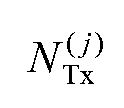
6. Base station (BSj) for a Communications cell (Bj) of a wireless communications network (1 ), the base station (BSj) being adapted to use space division multiple access, SDMA, and comprising: a selection unit (10) for selecting at least a first and a second mobile station (MS1 , MS2) in at least one of a plurality of beams (B1 0' to B4 0)) of the communications cell (Bj), the first mobile station (MS1 ) having higher Signal to Interference and Noise Ratio, SINR, than the second mobile station (MS2), a signal generation unit (11 ) for generating a downstream signal (bi0)) by combining a first data signal (di0)) for the first mobile station (MS1 ) with a second data signal (d2 0)) for the second mobile station (MS2) using nonzero amplitude scaling factors (f-i.Λ f2,i(l)), and a transmission unit (Njx^) for transmitting the downstream signal (bi0)) from the base station (BSj) to the first and second mobile stations (MS1 , MS2), wherein the signal generation unit (11 ) is adapted for selecting the amplitude scaling factors of the downstream signals of all the beams (B1^ to B4 0)) of the communications cell (Bj) taking intra-cell inter-beam interference into account such that at least one target transmission characteristic of the communications cell (Bj) is optimized.
7. Base station according to claim 6, wherein the signal generation unit (11 ) is adapted to generate a common pre-coding vector for the data signals (di0), d2 0)) of the selected mobile stations (MS1 , MS2) by combining a pre-coding vector of the first mobile station (MS1 ) with a pre-coding vector of the second mobile station (MS2).
8. Base station according to claim 6, wherein the selection unit (10) is adapted to select a first mobile station (MS1 ) and a second mobile station (MS2) having a difference of the SINR larger than a threshold parameter.
9. Communications cell (Bj), comprising: a base station (BSj) according to claim 6, a first mobile station (MS1 ) which is adapted, before recovering the first data signal (di0)) from the transmitted downstream signal, to remove the contribution of the second data signal (d2 0)) from the transmitted downstream signal, and, a second mobile station (MS2) which is adapted to recover the second data signal (d2 0)) from the transmitted downstream signal treating the contribution of the first data signal (di0)) as noise.
10. Wireless communications network (1 ) comprising a communications cell (Bj) according to claim 9 and at least one further communications cell (Bk) according to claim 9.
11. Wireless communications network according to claim 10, wherein a base station (BSk) of the further communications cell (Bk) comprises: a selection unit (10') adapted for selecting a third mobile station (MS3) in a beam (B2 (k)) of the further communications cell (Bk) also serving the second mobile station (MS2), the third mobile station (MS3) having higher SINR than the second mobile station (MS2), a signal generation unit (11 ') adapted to generate a further downstream signal by combining the second data signal (d2 0)) for the second mobile station (MS2) with a third data signal for the third mobile station (MS3), and a transmitting unit (NTx (k)) for transmitting the further downstream signal to the second and third mobile stations (MS2, MS3), wherein an open-loop or a closed-loop diversity scheme, preferably orthogonal block encoding, in particular space-frequency block encoding or space- time block encoding is used for transmitting the downstream signal (bi0)) and the further downstream signal to the second mobile station (MS2).
12. Computer program product comprising code means adapted to perform all the steps of the method according to claim 1.
Applications Claiming Priority (2)
| Application Number | Priority Date | Filing Date | Title |
|---|---|---|---|
| EP09290308.7 | 2009-04-27 | ||
| EP09290308A EP2246993A1 (en) | 2009-04-27 | 2009-04-27 | Extending SDMA by power loading for spatially non-separable users |
Publications (1)
| Publication Number | Publication Date |
|---|---|
| WO2010124928A1 true WO2010124928A1 (en) | 2010-11-04 |
Family
ID=41228608
Family Applications (1)
| Application Number | Title | Priority Date | Filing Date |
|---|---|---|---|
| PCT/EP2010/054780 Ceased WO2010124928A1 (en) | 2009-04-27 | 2010-04-13 | Extending sdma by power loading for spatially non-separable users |
Country Status (2)
| Country | Link |
|---|---|
| EP (1) | EP2246993A1 (en) |
| WO (1) | WO2010124928A1 (en) |
Citations (1)
| Publication number | Priority date | Publication date | Assignee | Title |
|---|---|---|---|---|
| WO2007133051A2 (en) | 2006-05-17 | 2007-11-22 | Lg Electronics Inc. | A method of implementing superposition coding for a forward link in a wireless commnication system |
Family Cites Families (1)
| Publication number | Priority date | Publication date | Assignee | Title |
|---|---|---|---|---|
| US20080260051A1 (en) * | 2007-04-23 | 2008-10-23 | Federico Boccardi | Method and apparatus for transmitting information simultaneously to multiple destinations over shared wireless resources |
-
2009
- 2009-04-27 EP EP09290308A patent/EP2246993A1/en not_active Withdrawn
-
2010
- 2010-04-13 WO PCT/EP2010/054780 patent/WO2010124928A1/en not_active Ceased
Patent Citations (1)
| Publication number | Priority date | Publication date | Assignee | Title |
|---|---|---|---|---|
| WO2007133051A2 (en) | 2006-05-17 | 2007-11-22 | Lg Electronics Inc. | A method of implementing superposition coding for a forward link in a wireless commnication system |
Non-Patent Citations (4)
| Title |
|---|
| BOCCARDI, F.; HUANG, H.: "Optimum power allocation for the MIMO-BC zero-forcing precoder with per-antenna power constraints", PROCEEDINGS OF INFORMATION SCIENCES AND SYSTEMS, March 2006 (2006-03-01) |
| KLEMENS FREUDENTHALER ET AL: "Novel SINR-to-CQI Mapping Maximizing the Throughput in HSDPA", IEEE WIRELESS COMMUNICATIONS AND NETWORKING CONFERENCE, 2007, WCNC 2007, 11 - 15 MARCH 2007, HONG KONG, IEEE OPERATIONS CENTER, PISCATAWAY, NJ, 1 March 2007 (2007-03-01), pages 2233 - 2237, XP031097555, ISBN: 978-1-4244-0658-6 * |
| PANASONIC: "Discussion on CQI Report Metric (SINR vs TBS)", 3GPP DRAFT; R1-074424, 3RD GENERATION PARTNERSHIP PROJECT (3GPP), MOBILE COMPETENCE CENTRE ; 650, ROUTE DES LUCIOLES ; F-06921 SOPHIA-ANTIPOLIS CEDEX ; FRANCE, vol. RAN WG1, no. Shanghai, China; 20071002, 2 October 2007 (2007-10-02), XP050107936 * |
| YUNJIAN JIA ET AL: "Impact of closed-loop power control on SDMA/TDMA system performance", VTC 2002-FALL. 2002 IEEE 56TH. VEHICULAR TECHNOLOGY CONFERENCE PROCEEDINGS. VANCOUVER, CANADA, SEPT. 24 - 28, 2002; [IEEE VEHICULAR TECHNOLGY CONFERENCE], NEW YORK, NY : IEEE, US LNKD- DOI:10.1109/VETECF.2002.1040532, vol. 3, 24 September 2002 (2002-09-24), pages 1825 - 1829, XP010608745, ISBN: 978-0-7803-7467-6 * |
Also Published As
| Publication number | Publication date |
|---|---|
| EP2246993A1 (en) | 2010-11-03 |
Similar Documents
| Publication | Publication Date | Title |
|---|---|---|
| Mao et al. | Rate-splitting multiple access for downlink communication systems: Bridging, generalizing, and outperforming SDMA and NOMA | |
| Shen et al. | MSE-based transceiver designs for the MIMO interference channel | |
| KR100995045B1 (en) | Method of transmitting precoded signal in cooperative multiple input / output communication system | |
| JP5628169B2 (en) | Method and apparatus for supporting multi-user and single-user MIMO in a wireless communication system | |
| RU2675383C2 (en) | Systems and methods for using inter-cell multiplexing gain in wireless cellular systems using distributed input-distributed output technology | |
| JP5119977B2 (en) | Radio resource allocation control apparatus and method, and radio base station | |
| US20120026956A1 (en) | Radio communication system, centralized station, control station apparatus, radio base station and coordinated transmission method | |
| TW201503622A (en) | System and method for applying channel reciprocity for radio frequency calibration in distributed communication and distributed output wireless communication | |
| WO2010032385A1 (en) | Radio communication device, radio communication system, and radio communication method | |
| TW201503620A (en) | System and method for applying inter-cell multiplex gain in a wireless cellular system via distributed input distributed output technology | |
| TW201501484A (en) | System and method for applying inter-cell multiplex gain in a wireless cellular system via distributed input distributed output technology | |
| Feng et al. | Interference management and user association for nested array-based massive MIMO HetNets | |
| Prashar et al. | Performance analysis of mimo-noma and siso-noma in downlink communication systems | |
| Kim et al. | Coordinated beamforming, interference-aware power control, and scheduling framework for 6G wireless networks | |
| Li et al. | Exploiting interactions of multiple interference for cooperative interference alignment | |
| Halabouni et al. | NOMA-MIMO in 5G network: a detailed survey on enhancing data rate | |
| Kim et al. | Coordinated beamforming with limited BS cooperation for multicell multiuser MIMO broadcast channel | |
| Kothari et al. | Massive MIMO Pre-coders for Cognitive Radio Network Performance Improvement: A Technological Survey | |
| WO2010124928A1 (en) | Extending sdma by power loading for spatially non-separable users | |
| Özbek et al. | Feedback strategies for multicell systems | |
| Iqbal et al. | Improving the performance of cell-edge users in 6G and beyond networks by utilizing a novel precoding-based hybrid CoMP transmission design | |
| Kaur et al. | Capacity enhancement of multiuser wireless communication system through adaptive non-linear pre coding | |
| Sk et al. | Energy‐aware power allocation using Ladybug Beetle Honey Badger Optimization in multiple‐input multiple‐output‐non‐orthogonal multiple access with multiple users | |
| Aboutorab et al. | A new resource allocation technique in MU-MIMO relay networks | |
| Salh et al. | Reduction Pilot Contamination in Downlink Multi-Cell for Massive MIMO Systems |
Legal Events
| Date | Code | Title | Description |
|---|---|---|---|
| 121 | Ep: the epo has been informed by wipo that ep was designated in this application |
Ref document number: 10713924 Country of ref document: EP Kind code of ref document: A1 |
|
| NENP | Non-entry into the national phase |
Ref country code: DE |
|
| 122 | Ep: pct application non-entry in european phase |
Ref document number: 10713924 Country of ref document: EP Kind code of ref document: A1 |