WO2010120113A2 - 예측 모드 선택 방법 및 장치와 그를 이용한 영상 부호화/복호화 방법 및 장치 - Google Patents
예측 모드 선택 방법 및 장치와 그를 이용한 영상 부호화/복호화 방법 및 장치 Download PDFInfo
- Publication number
- WO2010120113A2 WO2010120113A2 PCT/KR2010/002307 KR2010002307W WO2010120113A2 WO 2010120113 A2 WO2010120113 A2 WO 2010120113A2 KR 2010002307 W KR2010002307 W KR 2010002307W WO 2010120113 A2 WO2010120113 A2 WO 2010120113A2
- Authority
- WO
- WIPO (PCT)
- Prior art keywords
- prediction mode
- current block
- intra prediction
- bits
- bitstream
- Prior art date
- Legal status (The legal status is an assumption and is not a legal conclusion. Google has not performed a legal analysis and makes no representation as to the accuracy of the status listed.)
- Ceased
Links
Images


Classifications
-
- H—ELECTRICITY
- H04—ELECTRIC COMMUNICATION TECHNIQUE
- H04N—PICTORIAL COMMUNICATION, e.g. TELEVISION
- H04N19/00—Methods or arrangements for coding, decoding, compressing or decompressing digital video signals
- H04N19/10—Methods or arrangements for coding, decoding, compressing or decompressing digital video signals using adaptive coding
- H04N19/102—Methods or arrangements for coding, decoding, compressing or decompressing digital video signals using adaptive coding characterised by the element, parameter or selection affected or controlled by the adaptive coding
- H04N19/103—Selection of coding mode or of prediction mode
-
- H—ELECTRICITY
- H04—ELECTRIC COMMUNICATION TECHNIQUE
- H04N—PICTORIAL COMMUNICATION, e.g. TELEVISION
- H04N19/00—Methods or arrangements for coding, decoding, compressing or decompressing digital video signals
- H04N19/10—Methods or arrangements for coding, decoding, compressing or decompressing digital video signals using adaptive coding
- H04N19/102—Methods or arrangements for coding, decoding, compressing or decompressing digital video signals using adaptive coding characterised by the element, parameter or selection affected or controlled by the adaptive coding
- H04N19/103—Selection of coding mode or of prediction mode
- H04N19/11—Selection of coding mode or of prediction mode among a plurality of spatial predictive coding modes
-
- H—ELECTRICITY
- H04—ELECTRIC COMMUNICATION TECHNIQUE
- H04N—PICTORIAL COMMUNICATION, e.g. TELEVISION
- H04N19/00—Methods or arrangements for coding, decoding, compressing or decompressing digital video signals
- H04N19/10—Methods or arrangements for coding, decoding, compressing or decompressing digital video signals using adaptive coding
- H04N19/134—Methods or arrangements for coding, decoding, compressing or decompressing digital video signals using adaptive coding characterised by the element, parameter or criterion affecting or controlling the adaptive coding
- H04N19/136—Incoming video signal characteristics or properties
- H04N19/14—Coding unit complexity, e.g. amount of activity or edge presence estimation
-
- H—ELECTRICITY
- H04—ELECTRIC COMMUNICATION TECHNIQUE
- H04N—PICTORIAL COMMUNICATION, e.g. TELEVISION
- H04N19/00—Methods or arrangements for coding, decoding, compressing or decompressing digital video signals
- H04N19/60—Methods or arrangements for coding, decoding, compressing or decompressing digital video signals using transform coding
- H04N19/61—Methods or arrangements for coding, decoding, compressing or decompressing digital video signals using transform coding in combination with predictive coding
Definitions
- the present invention relates to a prediction mode selection method and apparatus, and an image encoding / decoding method and apparatus using the same. More specifically, the present invention relates to a method and apparatus for improving compression efficiency by simplifying a process of selecting a prediction mode for compressing an image, thereby improving compression speed and reducing the size of compressed data.
- Moving Picture Experts Group (MPEG) and Video Coding Experts Group (VCEG) have developed video compression techniques that are superior to the existing MPEG-4 Part 2 and H.263 standards.
- the new standard is called H.264 / AVC (Advanced Video Coding) and was jointly released as MPEG-4 Part 10 AVC and ITU-T Recommendation H.264.
- Image compression techniques such as H.264 / AVC use various prediction techniques such as inter prediction and intra prediction for efficient image compression.
- the intra prediction includes various prediction methods such as intra 4 ⁇ 4 prediction, intra 16 ⁇ 16 prediction, and intra 8 ⁇ 8 prediction, and each intra prediction includes a plurality of prediction modes.
- prediction is performed by selecting an optimal prediction mode having the best performance for compressing each block among a plurality of prediction modes. Therefore, the compression efficiency varies depending on which prediction mode is selected as the best prediction mode and the prediction is performed.
- a predetermined cost function is used after the prediction of the block is performed according to all prediction modes. After calculating the encoding cost, the prediction mode having the smallest encoding cost is selected.
- intra 4 ⁇ 4 prediction or intra 16 ⁇ 16 prediction requires prediction and calculating encoding cost by applying all prediction modes to determine an optimal prediction mode. This causes a problem in that the encoding process is complicated and the coding efficiency or the compression efficiency is lowered.
- the present invention has a main object of improving the compression efficiency by reducing the size of the compressed data by simplifying the process of selecting a prediction mode for compressing an image.
- an apparatus for encoding an image comprising: a prediction mode selector configured to select an intra prediction mode of a current block according to a change amount of a pixel value of an adjacent pixel of a current block to be encoded in an input image; An intra prediction encoder for encoding the residual block generated by intra prediction of the current block according to the intra prediction mode of the selected current block to generate coded coefficient bits; And generating and outputting a bitstream including the encoded coefficient bits and the prediction mode bits indicating the intra prediction mode of the selected current block in macroblock or subblock units, and selectively including the prediction mode bits in the bitstream according to the amount of change. It provides a video encoding apparatus comprising a bitstream generator to make.
- a method of encoding an image comprising: selecting an intra prediction mode of a current block according to a change amount of a pixel value of an adjacent pixel of a current block to be encoded in an input image; Encoding the residual block generated by intra-prediction of the current block according to the intra prediction mode of the selected current block, generating encoded coefficient bits; And generating a bitstream including encoded coefficient bits and prediction mode bits indicating an intra prediction mode of the selected current block in macroblock units or subblock units, and selectively including the prediction mode bits in the bitstream according to the amount of change. It provides a video encoding method comprising a.
- the apparatus for decoding an image from the bitstream in which the coefficient bits in which the residual block of the current block is encoded and the prediction mode bits of the current block are included in macroblock units or subblock units
- a bitstream extractor for extracting the encoded coefficient bits and the prediction mode bits
- a prediction mode selector for selecting a preset intra prediction mode or an intra prediction mode indicated by the extracted prediction mode bits as an intra prediction mode of the current block according to a change amount of pixel values of adjacent pixels of the current block
- an intra prediction decoder for reconstructing the residual block of the current block by decoding the encoded coefficient bits, and intra prediction of the current block according to the intra prediction mode of the selected current block to restore and output the current block.
- the method includes: from a bitstream in which coefficient bits in which a residual block of a current block is encoded and prediction mode bits of a current block are included in a macroblock unit or a subblock unit; Extracting the encoded coefficient bits and the prediction mode bits; Selecting an intra prediction mode indicated by a preset intra prediction mode or an extracted prediction mode bit as an intra prediction mode of the current block according to a change amount of pixel values of adjacent pixels of the current block; Reconstructing the residual block of the current block by decoding the encoded coefficient bits; Intra-prediction the current block according to the intra prediction mode of the selected current block; And reconstructing and outputting the current block by using the reconstructed residual block and the intra predicted current block.
- an apparatus for selecting a prediction mode comprising: a change amount calculator for calculating a change amount of a pixel value of an adjacent pixel of a current block; If the calculated variation is less than the threshold value, the preset intra prediction mode is selected as the intra prediction mode of the current block. If the calculated variation is greater than or equal to the threshold value, the selected intra prediction mode is selected according to the preset mode selection criteria.
- a mode selector which selects one intra prediction mode and selects the selected one intra prediction mode as an intra prediction mode of the current block; And a mode bit generator for generating and outputting a prediction mode bit indicating an intra prediction mode of the selected current block.
- a method of selecting a prediction mode comprising: calculating a change amount of a pixel value of an adjacent pixel of a current block; Selecting the preset intra prediction mode as the intra prediction mode of the current block when the calculated change amount is smaller than the threshold value; If the calculated variation is greater than or equal to the threshold, selecting one intra prediction mode from among a plurality of intra prediction modes according to a preset mode selection criterion to select one selected intra prediction mode as an intra prediction mode of the current block; ; And generating and outputting a prediction mode bit indicating an intra prediction mode of the selected current block.
- an apparatus for selecting a prediction mode comprising: a change amount calculator for calculating a change amount of a pixel value of an adjacent pixel of a current block; And if the calculated variation is less than the threshold, select the preset intra prediction mode as the intra prediction mode of the current block. If the variation is greater than or equal to the threshold, the coefficient block and the current block in which the residual block of the current block is encoded And a mode selector for selecting the intra prediction mode indicated by the prediction mode bits of the current block extracted from the bitstream including the prediction mode bits of the macroblock unit or the subblock unit as the intra prediction mode of the current block.
- a prediction mode selection device for selecting the intra prediction mode indicated by the prediction mode bits of the current block extracted from the bitstream including the prediction mode bits of the macroblock unit or the subblock unit as the intra prediction mode of the current block.
- a method of selecting a prediction mode comprising: calculating a change amount of a pixel value of an adjacent pixel of a current block; If the calculated change amount is smaller than the threshold, selecting the preset intra prediction mode as the intra prediction mode of the current block; And the prediction mode bits of the current block extracted from a bitstream in which the residual bits of the current block are encoded and the prediction mode bits of the current block are included in macroblock or subblock units when the amount of change is greater than or equal to the threshold. It provides a prediction mode selection method comprising the step of selecting the intra prediction mode indicated by the intra prediction mode of the current block.
- the compression process can be improved by simplifying a process of selecting a prediction mode for compressing an image, and the compression efficiency can be improved by reducing the size of the compressed data.
- FIG. 1 is a block diagram schematically illustrating a video encoding apparatus
- FIG. 2 is a block diagram schematically illustrating a video decoding apparatus
- 3 is an exemplary diagram illustrating nine intra 4 ⁇ 4 prediction modes
- 4 is an exemplary diagram illustrating four intra 16 ⁇ 16 prediction modes
- FIG. 5 is a block diagram schematically illustrating an image encoding apparatus according to an embodiment
- FIG. 6 is a block diagram schematically illustrating an apparatus for selecting a prediction mode for encoding according to an embodiment
- FIG. 7 is an exemplary diagram for describing a change amount of pixel values of adjacent pixels according to an exemplary embodiment
- FIG. 8 is a diagram illustrating nine intra 4 ⁇ 4 prediction modes in which an intra prediction order is changed according to an embodiment.
- FIG. 9 is an exemplary view briefly illustrating a bitstream included in macroblock units configured according to an embodiment
- FIG. 10 is a diagram schematically illustrating a bitstream included in a unit of a subblock configured according to an embodiment
- FIG. 11 is a flowchart illustrating a prediction mode selection method for encoding, according to an embodiment.
- FIG. 12 is a flowchart illustrating an image encoding method, according to an embodiment.
- FIG. 13 is a block diagram schematically illustrating an image decoding apparatus according to an embodiment
- FIG. 14 is a block diagram schematically illustrating an apparatus for selecting a prediction mode for decoding according to an embodiment
- 15 is a flowchart illustrating a method of selecting a prediction mode for decoding, according to an embodiment.
- 16 is a flowchart illustrating an image decoding method, according to an exemplary embodiment.
- a video encoding apparatus (Video Encoding Apparatus), a video decoding apparatus (Video Decoding Apparatus) or a prediction mode selection apparatus (Prediction Mode Selection Apparatus) to be described later will be a personal computer (PC), notebook computer, personal digital assistant (PDA) : Personal Digital Assistant (PMP), Portable Multimedia Player (PMP), PlayStation Portable (PSP: PlayStation Portable), Mobile Communication Terminal (Mobile Communication Terminal), etc., for communicating with various devices or wired or wireless communication network It refers to various devices including a communication device such as a communication modem, a memory for storing various programs and data for encoding or decoding an image or selecting a prediction mode, and a microprocessor for executing and operating a program.
- a communication device such as a communication modem
- a memory for storing various programs and data for encoding or decoding an image or selecting a prediction mode
- a microprocessor for executing and operating a program.
- the image encoded in the bitstream by the video encoding apparatus is real-time or non-real-time through the wired or wireless communication network, such as the Internet, local area wireless communication network, wireless LAN network, WiBro network, mobile communication network, or the like, or a cable, universal serial bus (USB: Universal)
- the image decoding apparatus may be transmitted to a video decoding apparatus through a communication interface such as a serial bus, decoded by the video decoding apparatus, reconstructed, and played back.
- the image encoding apparatus and the image decoding apparatus may be provided with a function for performing not only intra prediction but also inter prediction.
- the image encoding apparatus and the image decoding apparatus do not have a direct relationship with the embodiment of the present invention, a detailed description will be provided to prevent confusion.
- a moving picture is composed of a series of pictures, and each picture is divided into blocks.
- Each block is largely classified into an intra block and an inter block according to an encoding method.
- An intra block refers to a block that is encoded by using an intra prediction coding method.
- An intra prediction coding is performed by using pixels of blocks previously encoded, decoded, and reconstructed in a current picture that performs current encoding.
- a prediction block is generated by predicting pixels of a block and a difference value with pixels of the current block is encoded.
- An inter block refers to a block that is encoded using inter prediction coding.
- Inter prediction coding generates a prediction block by predicting a current block within a current picture by referring to one or more past or future pictures, and then generates a current block. This is a method of encoding the difference value with.
- a picture referred to for encoding or decoding the current picture is referred to as a reference picture.
- FIG. 1 is a block diagram schematically illustrating a video encoding apparatus.
- the image encoding apparatus 100 may include a predictor 110, a subtractor 120, a transformer 130, a quantizer 140, an encoder 150, an inverse quantizer, and an inverse quantizer. 160, an inverse transformer 170, and an adder 180.
- the predictor 110 intra-predictions the current block to generate a predicted block. That is, when the block to be currently encoded, that is, the current block is input, is input to the predictor 110, the original pixel values of the pixels of the current block are included in the plurality of intra prediction modes. A prediction block having predicted pixel values is generated and output by predicting according to a prediction direction of a selected intra prediction mode.
- the plurality of intra prediction modes may be a plurality of intra prediction modes according to a block mode of the current block or a plurality of intra prediction modes preset by a user.
- the multiple intra prediction modes are the prediction modes of the intra 16x16 mode defined by the H.264 / AVC standard.
- the plurality of intra prediction modes may be the horizontal mode and the vertical mode among the intra 16x16 modes. have.
- the subtractor 120 subtracts the current block and the prediction block to generate a residual block of the current block.
- the output residual block includes a residual signal, which has a value obtained by subtracting the prediction pixel value of the prediction block from the original pixel value of the current block.
- the transformer 130 transforms the residual block to generate a transformed block. That is, the transformer 130 converts the residual signal of the residual block output from the subtractor 120 into a frequency domain to generate and output a transform block having a transform coefficient.
- a method of transforming the residual signal into the frequency domain a Discrete Cosine Transform (DCT) -based transform or a Hadamard Transform (DCT) may be used, but the present invention is not limited thereto.
- Various transformation techniques such as the technique may be used, and the residual signal is transformed into a frequency domain and transformed into transformation coefficients.
- the quantizer 140 quantizes the transform block to generate a quantized transform block. That is, the quantizer 140 quantizes the transform coefficients of the transform block output from the transformer 130 to generate and output a quantized transform block having quantized transform coefficients.
- DZUTQ dead zone uniform threshold quantization
- DZUTQ quantization weighted matrix
- various quantization methods such as quantization improved therefrom may be used.
- the encoder 150 encodes the quantized transform block and outputs a bitstream. That is, the encoder 150 uses various encoding techniques, such as entropy encoding, on a frequency coefficient string scanned by various scan methods such as zigzag scan of the quantized transform coefficients output from the quantizer 140. To generate and output a bitstream including additional information necessary for encoding and decoding the corresponding block (for example, information on a prediction mode, a quantization coefficient, a motion vector, etc.). do.
- Inverse quantizer 160 inverse quantizes the quantized transform block. That is, the inverse quantizer 160 inversely quantizes and outputs quantized transform coefficients of the quantized transform block output from the quantizer 140.
- Inverse transformer 170 inversely transforms an inverse quantized transform block. That is, the inverse transformer 170 inversely transforms the transform coefficients inversely quantized by the inverse quantizer 160 to restore a residual block having the reconstructed residual coefficients.
- the adder 180 reconstructs the current block by adding the prediction block predicted by the predictor 110 and the residual block inversely transformed and reconstructed by the inverse transformer 170.
- the reconstructed current block may be transferred to the predictor 110 and used to predict another block such as the next block or the next picture.
- FIG. 2 is a block diagram schematically illustrating a video decoding apparatus.
- the image decoding apparatus 200 may include a decoder 210, an inverse quantizer 220, an inverse transformer 230, a predictor 240, and an adder 250.
- the decoder 210 extracts a quantized transform block by decoding the bitstream. That is, the decoder 210 decodes and inversely scans the bit string extracted from the input bitstream to restore the quantized transform block having the quantized transform coefficients. In this case, the decoder 210 decodes using an encoding technique such as entropy encoding used by the encoder 150 of the image encoding apparatus 100.
- Inverse quantizer 220 inverse quantizes the quantized transform block. That is, the inverse quantizer 220 inverse quantizes the quantized transform coefficients of the quantized transform block output from the decoder 210. In this case, the inverse quantizer 220 performs inverse quantization by performing the inverse quantization technique used by the quantizer 140 of the image encoding apparatus 100.
- the inverse transformer 230 inversely transforms the inverse quantized transform block output from the inverse quantizer 220 to restore the residual block. That is, the inverse transformer 230 reconstructs the residual block having the reconstructed residual signal by inversely transforming the inverse quantized transform coefficients of the inverse quantized transform block output from the inverse quantizer 220. Inverse conversion is performed by performing the conversion technique used in the converter 130 of the inverse.
- the predictor 240 generates a prediction block by predicting the current block according to the prediction direction according to the intra prediction mode extracted from the bitstream.
- the adder 250 reconstructs the current block by adding the prediction block and the reconstructed residual block. That is, the adder 250 adds the predicted pixel value of the predicted block output from the predictor 240 and the restored residual signal of the reconstructed residual block output from the inverse transformer 230 to calculate a reconstructed pixel value of the current block. Restore the current block.
- an optimal intra prediction mode is selected from a plurality of intra prediction modes as shown in FIGS. 3 and 4, and the selected optimal intra prediction mode is selected. Predict the block according to the prediction direction.
- 3 is an exemplary diagram illustrating nine intra 4x4 prediction modes.
- intra 4 ⁇ 4 prediction includes a vertical mode, a horizontal mode, a direct current mode, a diagonal down-left mode, and a diagonal down-right. There are nine prediction modes, including vertical-right mode, horizontal-down mode, vertical-left, and vertical-up modes, and nine prediction modes. Is given a mode number. Intra 8 ⁇ 8 prediction also has nine prediction modes similar to intra 4 ⁇ 4 prediction.
- 4 is an exemplary diagram illustrating four intra 16 ⁇ 16 prediction modes.
- intra 16 ⁇ 16 prediction includes four prediction modes including a vertical mode, a horizontal mode, a DC mode, and a plane mode. The mode number is given.
- FIG. 5 is a block diagram schematically illustrating an image encoding apparatus according to an embodiment.
- the image encoding apparatus 500 may include a prediction mode selector 510, an intra prediction encoder 520, and a bitstream generator 530.
- the prediction mode selector 510 selects the intra prediction mode of the current block according to the variation of the pixel value of the adjacent pixel of the current block to be encoded in the input image.
- the neighboring pixel of the current block may be one of pixels included in the neighboring block around the current block, and in particular, may be a pixel adjacent to the current block among the pixels included in the neighboring block.
- the adjacent pixels of the current block may be pixels that are encoded, decoded, and reconstructed by the intra prediction encoder 520.
- the prediction mode selector 510 may select the preset intra prediction mode as the intra prediction mode of the current block when the amount of change in the pixel value of the adjacent pixel of the current block is smaller than the threshold Thr.
- the preset intra prediction mode may include an intra prediction mode (for example, a DC mode in the case of H.264 / AVC) that predicts an average value of pixel values of adjacent pixels of the current block as predicted pixel values of the pixels of the current block. It may be the same.
- the prediction mode selector 510 selects one intra prediction mode from among a plurality of intra prediction modes according to a preset mode selection criterion when the amount of change in pixel values of adjacent pixels of the current block is greater than or equal to a threshold value.
- the intra prediction mode may be selected as the intra prediction mode of the current block.
- the prediction mode selector 510 selects one intra prediction mode by applying each of the plurality of intra prediction modes to preset mode selection criteria, and selects a DC mode among the plurality of intra prediction modes to the preset mode selection criteria.
- the preset mode selection criterion may be a mode selection criterion previously promised by the image encoding apparatus 500 and the image decoding apparatus 900 to be described later.
- RDO Rate-Distortion Optimization
- the prediction mode selector 510 may calculate an amount of change of pixel values of adjacent pixels of the current block by using a degree of scattering.
- the scatter diagram may be a dispersion, a standard deviation, a mean deviation, a quarter deviation, or the like.
- the prediction mode selector 510 may select the intra prediction mode of the current block by comparing the amount of change in pixel values of adjacent pixels of the current block with a threshold.
- the threshold may be set according to things such as the quantization coefficient and the quantization step size of the current block.
- the intra prediction encoder 520 encodes the residual block generated by intra prediction of the current block according to the intra prediction mode of the selected current block to generate coded coefficient bits.
- the intra prediction encoder 520 may be configured like the image encoding apparatus 100 described above with reference to FIG. 1. That is, the intra prediction encoder 520 generates a prediction block by predicting a current block according to the intra prediction mode selected by the prediction mode selector 510, and generates a residual block by subtracting the generated prediction block from the current block.
- the residual signal of the residual block may be transformed and quantized to generate quantized frequency coefficients, and then scanned and entropy encoding may be performed to generate encoded coefficient bits. In this case, the transform and / or quantization process may be selectively omitted depending on the implementation method.
- the current block may be determined in units of macroblocks or in units of subblocks.
- the macroblock may be 16 ⁇ 16 and the subblock may be 4 ⁇ 4, but the macroblock may be a block having various sizes.
- the macroblock may be a block of M ⁇ N size (where M and N are integers) such as 16 ⁇ 16 size, 32 ⁇ 32 size, 8 ⁇ 8 size, etc., and the subblock is larger than the size of the macroblock. If it is small, it may be a block of M ⁇ N size (where M and N are integers) such as 16 ⁇ 16 size, 32 ⁇ 32 size, 8 ⁇ 8 size, and the like.
- the intra prediction encoder 520 may reconstruct the residual block by inversely quantizing and inversely transforming the quantized frequency coefficients, and reconstruct the current block by adding the prediction block and the reconstructed residual block.
- the reconstructed pixels stored as described above may be transferred to the prediction mode selector 510 and used as adjacent pixels of the current block.
- the bitstream generator 530 generates a bitstream including coefficient bits encoded in macroblock units or subblock units and prediction mode bits indicating intra prediction modes of the selected current block. And output, but selectively includes the prediction mode bits in the bitstream according to the amount of change.
- the bitstream generator 530 may generate and output a bitstream by allocating coefficient bits encoded in macroblock units or subblock units before prediction mode bits.
- the bitstream generator 530 includes the encoded coefficient bits and the prediction mode bits in the bitstream in units of macroblocks, it is preferable to include the encoded coefficient bits before the prediction mode bits, and the bitstream generator 530. ) Includes the encoded coefficient bits and the prediction mode bits in the bitstream in units of subblocks, the encoded coefficient bits and the prediction mode bits may be freely included in the bitstream regardless of the arrangement order.
- the bitstream generator 530 includes a bitstream including both the encoded coefficient bits for the current block and the prediction mode bits for the current block only when the amount of change in pixel values of adjacent pixels of the current block is greater than or equal to the threshold. If the amount of change of the pixel value of the adjacent pixel of the current block is smaller than the threshold, the prediction mode bit for the current block is not included in the bitstream. Thus, if the amount of change in the pixel value of adjacent pixels in the current block is less than the threshold, the bitstream contains only the encoded coefficient bits of the current block.
- FIG. 6 is a block diagram schematically illustrating an apparatus for selecting a prediction mode for encoding according to an embodiment.
- the prediction mode selection apparatus for encoding according to an embodiment may be implemented by the prediction mode selector 510 in FIG. 5.
- the prediction mode selecting apparatus for encoding according to an embodiment is called a prediction mode selector 510.
- the prediction mode selector 510 may include a variation calculator 610, a mode selector 620, and a mode bit generator 630.
- the change amount calculator 610 calculates a change amount of the pixel value of the adjacent pixel of the current block.
- the change calculator 610 may calculate a change amount of pixel values of adjacent pixels among pixels included in the neighboring block of the current block by using a scatter diagram.
- the scatter diagram may be a statistical index indicating such things as variance, standard deviation, mean deviation, and quadrant deviation of adjacent pixels. Therefore, the amount of change in the pixel value of the adjacent pixel may be an indicator indicating how similar the adjacent pixels of the current block are to each other. The smaller the change amount, the more adjacent pixels in the current block can be regarded as similar.
- the change amount calculator 610 uses the equation 1 to determine the adjacent pixel.
- the change amount ⁇ p of the pixel value can be calculated.
- u k Pixel value of M adjacent pixels located at the top of the current block.
- the mode selector 620 selects the preset intra prediction mode as the intra prediction mode of the current block when the calculated change amount is smaller than the threshold value, and according to the preset mode selection criterion when the calculated change amount is greater than or equal to the threshold value.
- One intra prediction mode is selected from among a plurality of intra prediction modes to select one selected intra prediction mode as an intra prediction mode of the current block. That is, the mode selector 620 calculates and sets a threshold value appropriately, evaluates the similarity of adjacent pixels by comparing the change amount of the pixel value of the adjacent pixel calculated by the change amount calculator 610 with the threshold value, and evaluates the similarity. According to the intra prediction mode of the current block is selected.
- all intra prediction modes are performed, such as rate-distortion optimization, so that one intra prediction mode having a minimum rate-distortion cost is optimal.
- Select the prediction mode to select the intra prediction mode of the current block.
- the similarity of adjacent pixels of the current block is large, it is not necessary to perform rate-distortion optimization for a plurality of intra prediction modes, and the intra prediction mode having the best prediction efficiency when the similarity of adjacent pixels is large is selected. It is efficient to select in intra prediction mode.
- 7A of FIG. 7 illustrates pixels used to predict a block according to an intra 4 ⁇ 4 mode of H.264.
- 16 pixels a to p represent pixels of the current block
- 13 pixels A to M represent adjacent pixels of the current block.
- Intra prediction of the current block shown in 7A using nine prediction modes according to the intra 4 ⁇ 4 mode shown in FIG. 3 is performed according to nine prediction directions using pixel values of A to M that are already compressed and reconstructed. Perform intra prediction and encode.
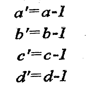
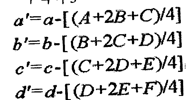
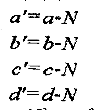
- Equation 2 when intra prediction is performed in the horizontal direction according to the horizontal mode, which is the first prediction mode shown in FIG. 3, the a, b, c, and d pixels of the first row of the current block are represented by Equation 2 and the following equation. It is predicted as
- the a, b, c, and d pixels of the first row of the current block are represented by the following equation. It is predicted as 3.
- a residual signal may be generated by performing prediction using pixel values of adjacent pixels in a similar manner.
- the current block may be predicted according to nine prediction modes for intra 4x4 mode prediction. It can be seen that all of the same results can be obtained. Therefore, if all the adjacent pixels of the current block have the same pixel value, it can be seen that the prediction performance or the compression performance does not degrade even if intra prediction is performed according to any one prediction mode.
- the prediction values of the respective prediction directions are similar, and thus intra prediction is performed according to one intra prediction mode as in the case where the neighboring pixels of the current block are all the same. Even if the prediction performance and the compression performance may not be degraded.
- the mode selector 620 sets an intra prediction mode having the best prediction efficiency and determines that the similarity of adjacent pixels is large because the amount of change calculated by the variation calculator 610 is smaller than the threshold value.
- the complicated intra prediction mode selection process may be omitted, and the preset intra prediction mode may be selected as the intra prediction mode of the current block. In this way, the computational amount for selecting the intra prediction mode of the current block can be reduced without degrading the performance of the intra prediction, thereby simplifying the implementation of the system and improving the compression performance by reducing the encoding speed.
- the preset intra prediction mode refers to an intra prediction mode that is previously promised and set in the image encoding apparatus and the image decoding apparatus, and thus may be predicted in the same intra prediction mode in the decoding process.
- the preset intra prediction mode may be, for example, an intra prediction mode such as a DC mode, which is an intra prediction mode that predicts an average value of pixel values of adjacent pixels as a prediction value, but is not limited thereto. Can be set.
- the mode selector 620 determines that the change amount calculated by the change amount calculator 610 is greater than or equal to the threshold value, and thus the similarity of adjacent pixels is small, the mode selector 620 performs intra prediction of one of a plurality of intra prediction modes according to a preset mode selection criterion. Mode is selected to select one selected intra prediction mode as the intra prediction mode of the current block.
- the preset mode selection criterion refers to a criterion for selecting an intra prediction mode that is optimal for a current block among a plurality of intra prediction modes in the image encoding apparatus and the image decoding apparatus. Can be set.
- the preset mode selection criterion may be, for example, rate-distortion optimization.
- Rate-distortion optimization is a rate-distortion using a predetermined cost function by predicting and encoding a current block according to each of a plurality of intra prediction modes. It is a technique of calculating an RD Cost (Rate Cost-Distortion Cost) and selecting an intra prediction mode in which the calculated rate-distortion cost is minimal as an optimal intra prediction mode.
- the above-described predetermined cost function may be a sum of absolute value (SAD), sum of absolute transformed difference (SATD), sum of squared difference (SSD), mean of absolute difference (MAD), lagrange function, and the like.
- SAD is the sum of the absolute values of the residual signal values of the 4x4 block.
- the SATD is a value obtained by adding an absolute value of coefficients generated by applying a Hadamard transform to a value of a residual signal of a 4 ⁇ 4 block.
- the SSD is a sum of squared values of the residual signal of the 4x4 block
- the MAD is an average value of the absolute values of the residual signal of the 4x4 block.
- the Lagrange function is a cost function created by including the length information of the bitstream in the cost function.
- the mode selector 620 may be configured to select one intra prediction mode from among a plurality of intra prediction modes according to a preset mode selection criterion so that the mode selector 620 selects the intra prediction mode of the current block.
- the order of applying the intra prediction mode to the preset mode selection criteria may be changed. That is, the mode selector 620 may select one intra prediction mode by sequentially applying each of the plurality of intra prediction modes to preset mode selection criteria. In this case, the mode selection criterion is selected from the DC mode among the plurality of intra prediction modes. Finally you can apply.
- the DC mode using the average value of the pixel values of the adjacent pixels as the intra prediction value is applied to the preset mode selection criteria. If the order is the second as shown in Fig. 3, it is because the probability that the second prediction mode is determined to be the optimal intra prediction mode is lowered. That is, once it is determined that the change amount of adjacent pixels is large by comparing the change amount and the threshold value, since the DC mode is unlikely to be selected as the optimal intra prediction mode for the current block, the order in which the DC mode is applied to the preset mode selection criteria As shown in FIG. 8, it is efficient to arrange the last one.
- the intra prediction mode that is optimal for the current block may be selected more quickly.
- it is applied to the preset mode selection criteria in the order of vertical mode, horizontal mode, diagonal left mode, diagonal right mode, vertical right mode, horizontal bottom mode, vertical left mode, horizontal top mode, and DC mode.
- One intra prediction mode may be selected as the intra prediction mode of the current block. To this end, as shown in FIG.
- the vertical mode and the horizontal mode are maintained as mode 0 and mode 1, respectively, the diagonal left mode is changed to mode 2, the diagonal right mode is changed to mode 3, and Change the vertical right mode to mode 4, the horizontal down mode to mode 5, the vertical left mode to mode 6, the horizontal top mode to mode 7, and the DC mode to mode 8 You can change the mode.
- the order of the four intra prediction modes of the intra 16x16 mode can also be changed so that the DC mode is the last.
- a threshold value which is a criterion for evaluating the degree of similarity of adjacent pixels, is compared with the calculated change amount other than the change amount of pixel values of adjacent pixels calculated by the change amount calculator 610.
- the mode selector 620 must be set appropriately. That is, the threshold value is information that serves as a criterion for determining the degree of similarity between adjacent pixels of the current block. Therefore, when the calculated change amount of the pixel value of the adjacent pixel is smaller than the set threshold value, the adjacent pixels of the current block may be determined to have similarities with each other.
- the mode selector 620 may calculate and set a threshold.
- the threshold value may be adaptively calculated and set according to a quantization coefficient (QP) and a quantization step size (Q step ).
- the quantization coefficient may be set to any integer value as a coefficient for adjusting the quantization.
- the quantization coefficient is set to one of integers from 0 to 51.
- the quantization step size is set based on quantization coefficients as information for adjusting the quantization intensity. For example, in H.264, the size of the quantization step is doubled whenever the quantization coefficient is increased by 6, so the size of the quantization step may be increased by 2 times whenever the quantization coefficient is increased by 6. .
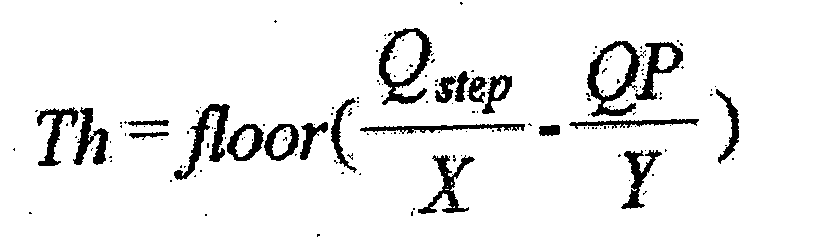
- This threshold may be calculated and set using Equation 6.
- the threshold value may be set by substituting a specific constant into X and substituting a specific constant into Y in Equation 6.
- These constants X and / or constants Y may be substituted by changing the value according to a set value of the quantization coefficient and / or quantization step size or a desired threshold value.
- the mode bit generator 630 may generate and output a prediction mode bit indicating the intra prediction mode of the selected current block. At this time, the mode bit generator 630 generates and outputs a prediction mode bit only when the change amount calculated by the change amount calculator 610 is greater than or equal to the threshold value, and does not generate the prediction mode bit when the change amount is less than the threshold value. You may not.
- the prediction mode bits may be included in the bitstream together with the encoded coefficient bits in the residual block of the current block. When the prediction blocks are included in the bitstream in units of macroblocks, the encoded coefficient bits may be allocated before the prediction mode bits. When included in the bitstream in units of subblocks, the encoded coefficient bits and the prediction mode bits may be included in the bitstream regardless of the order of each other.
- FIG. 9 is an exemplary view briefly illustrating a bitstream generated in units of macroblocks according to an embodiment.
- a bitstream generated in units of macroblocks by the bitstream generator 530 may be configured as shown in FIG. 9.
- 9A illustrates a structure of a bitstream generated according to a conventional compression technique
- FIG. 9B illustrates a structure of a bitstream generated in macroblock units according to an embodiment.
- the bitstream generated according to a conventional compression technique as shown in 9A shows a structure in which the mode bit field to which the prediction mode bits are assigned is placed in front of the coefficient bit field to which the encoded coefficient bits are assigned, while According to an embodiment, a bitstream generated in units of macroblocks has a structure in which a mode bit field to which prediction mode bits are allocated is disposed behind a coefficient bit field to which encoded coefficient bits are allocated.
- the structure of the bitstream shown in 9B shows the structure of the bitstream in which the encoded coefficient bits and the prediction mode bits are generated in macroblock units.
- the encoding of all the blocks of the macroblock is performed in the coefficient bit field to which the encoded coefficient bits are assigned. While the counted coefficient bits are included, the mode bit field to which the prediction mode bits are allocated may not include the prediction mode bits of all blocks (or subblocks) of the macroblock.
- the prediction mode selector 510 determines that the similarity of adjacent pixels is large when the amount of change of adjacent pixels of the current block is smaller than a threshold value, and selects a preset intra prediction mode as an intra prediction mode of the current block. Since the image encoding apparatus and the image decoding apparatus are set in advance, the image decoding apparatus may perform the intra prediction mode of the current block in the same manner as the image encoding apparatus, even if the bitstream does not include the prediction mode bit indicating the intra prediction mode of the corresponding block. It can be seen that the preset intra prediction mode. Therefore, when the intra prediction mode of the current block is selected as the preset intra prediction mode, the prediction mode bits for the block may not be included in the mode bit field, thereby improving the compression performance by reducing the size of the compressed data. You can.
- the reason why the bitstream generated in units of macroblocks is different from the structure of the bitstream generated according to a conventional compression technique according to an embodiment is as described above. This is because, when the mode is selected as the preset intra prediction mode, the prediction mode bits of the corresponding block are not included in the mode bit field of the bitstream. If the intra prediction mode of the current block is selected as the preset intra prediction mode, the mode bit field is preceded by the coefficient bit field like a bit stream generated according to a conventional compression technique without including the prediction mode bit in the mode bit field.
- the image decoding apparatus that receives the bitstream cannot normally distinguish the prediction mode bits and the coefficient bits. That is, the apparatus for decoding an image cannot know how far from the bitstream the prediction mode bit is or where the encoded coefficient bit starts.
- the order of the bitstream is changed by transmitting a coefficient bit field to which coded coefficient bits are allocated first, and then transmitting a mode bit field to which a prediction mode bit is allocated later.
- the image decoding apparatus may normally extract the encoded coefficient bits for each block of the macroblock based on the format of the predetermined encoded coefficient bits. Subsequently, the image decoding apparatus determines whether to select a preset intra prediction mode or an intra prediction mode indicated by the prediction mode bits as an intra prediction mode of the corresponding block according to the amount of change in the pixel value of the adjacent pixel of each block.
- intra prediction of the block is performed using the preset intra prediction mode without extracting the prediction mode bits of the bitstream, and the intra prediction mode indicated by the prediction mode bits is intra. Only when the prediction mode is selected, the prediction mode bit can be normally extracted from the mode bit field of the bitstream, and the intra block can be normally intra predicted by the intra prediction mode indicated by the prediction mode bit.
- FIG. 10 is a diagram schematically illustrating a bitstream included in a subblock unit configured according to an embodiment.
- the structure of the bitstream illustrated in FIG. 9B of FIG. 9 illustrates a structure of a bitstream generated by including encoded coefficient bits and prediction mode bits in macroblock units.
- a bitstream according to an embodiment may be generated by including encoded coefficient bits and prediction mode bits in subblock units.
- FIG. 10 illustrates a structure of a bitstream generated according to an embodiment when intra prediction coding is performed by dividing a 16 ⁇ 16 macroblock into 16 4 ⁇ 4 subblocks.
- 10 illustrates a structure of a bitstream generated by including prediction mode bits in macroblock units
- 10B illustrates a structure of a bitstream generated by including encoded coefficient bits and prediction mode bits in subblock units.
- 16 4x4 subblocks included in the 16x16 macroblock are included in the coefficient bit field.
- the first prediction mode bits for each of the sixteen 4x4 subblocks included in the 16x16 macroblock also included in the mode bit field.
- Sixteenth prediction mode bits are included in succession. That is, the coefficient bit field is allocated before the mode bit field and included in the bitstream.
- some or all of the first to sixteenth prediction mode bits may be selectively included in the bitstream according to the amount of change of the adjacent pixel of each subblock.
- the bitstream is generated by including the coefficient bits and the prediction mode bits encoded in sub-block units, as shown in 10B, one sub for each of the 16 4x4 subblocks included in the 16x16 macroblock. After the coefficient bit field and the mode bit field for the block are arranged, the coefficient bit field and the mode bit field for the next subblock are arranged.
- the first prediction mode bit is placed after the first coefficient bit and then the second prediction mode bit is placed after the second coefficient bit, and arranged in this order so that at last the sixteenth prediction bit is followed by the sixteenth coefficient bit. The bit is placed.
- the prediction mode bit is included or not included in the bitstream according to the amount of change in the pixel value of the adjacent pixel of the current block. Accordingly, the bitstream shown in 10B represents a case where the prediction mode bits of all subblocks of the 16 4x4 sized subblocks included in the 16x16 sized macroblock are included in the bitstream.
- the neighboring pixels of the second subblock and the third subblock are included.
- the prediction mode bits of the corresponding subblock that is, the second subblock and the third subblock, are not generated or generated. It is not included because it is not assigned to the bitstream. 10C illustrates this case by way of example.
- the prediction mode bits are allocated before the encoded coefficient bits in units of subblocks, but the present invention is not limited thereto and may be allocated in the reverse order. That is, the encoded coefficient bits may be allocated before the prediction mode bits to configure the bitstream.
- the image decoding apparatus predicts a corresponding subblock by comparing a change amount of adjacent pixels of a subblock to be encoded in advance with a threshold value. This is because it is possible to determine whether the mode bit is generated and included in the bitstream.
- the bitstream corresponds to the bitstream. Extract only the encoded coefficient bits of the subblock, decode the corresponding subblock, and change the pixel value of the adjacent pixel of the next subblock to be greater than or equal to the threshold so that the prediction mode bits of the subblock are included in the bitstream. If it is determined that the macroblock is decoded by extracting the prediction mode bits as well as the encoded coefficient bits of the corresponding subblock in the bitstream.
- an image decoding apparatus that receives and decodes a bitstream decodes the corresponding macroblock. Since the coded coefficient bits and the prediction mode bits for each of the sixteen subblocks must be stored in the same memory as the buffer until the C is completed, the required memory capacity is increased. In addition, in the case of configuring the bitstream by including the coefficient bits and the prediction mode encoded in macroblock units, as described above, the coefficient bit field to which the encoded coefficient bits are allocated is preceded by the mode bit field to which the prediction mode bits are allocated. The configuration of the bitstream is not flexible because it must be allocated and included in the bitstream.
- FIG. 11 is a flowchart illustrating a prediction mode selection method for encoding, according to an embodiment.
- an intra prediction mode of the current block should be selected.
- the prediction mode selector that is, the prediction mode selector 510 calculates a change amount of pixel values of adjacent pixels of the current block (S1110), and compares the calculated change amount with a threshold value (S1120).
- the prediction mode selector 510 determines that the similarity of adjacent pixels of the current block is large and selects the preset intra prediction mode as the intra prediction mode of the current block (S1130). In this case, since the preset intra prediction mode selected as the intra prediction mode of the current block is previously promised in the image decoding apparatus, the prediction mode selector 510 does not generate a prediction mode bit for indicating the intra prediction mode of the current block. (S1140). If a prediction mode bit is generated, it is not included in the bitstream.
- the prediction mode selector 510 determines that the similarity of the adjacent pixels of the current block is small and determines one of the plurality of intra prediction modes according to a preset mode selection criterion.
- the intra prediction mode is selected (S1150), and the selected one intra prediction mode is selected as the intra prediction mode of the current block (S1160).
- a prediction mode bit indicating an intra prediction mode of the selected current block is generated (S1170). The generated prediction mode bits are included in the bitstream.
- the prediction mode selector 510 when the intra prediction mode of the current block is selected, the prediction mode selector 510 is equal to the rate-distortion optimization in a certain case (when the amount of change in the pixel value of the adjacent pixel is smaller than the threshold value). Since it is possible to select a preset intra prediction mode as an intra prediction mode of the current block without performing a complicated process of selecting an optimal intra prediction mode according to all selection criteria, the amount of calculation for selecting an intra prediction mode can be reduced. Not only can the implementation be simplified, but the coding speed can be improved, thereby improving the compression performance.
- FIG. 12 is a flowchart illustrating an image encoding method, according to an exemplary embodiment.
- the intra prediction mode of the current block is selected according to the amount of change in pixel values of adjacent pixels of the current block to be encoded (S1210), and the residual block generated by intra prediction of the current block is encoded according to the intra prediction mode of the selected current block.
- the bitstream is output by including the coefficient bits and the prediction mode bits encoded by the residual block of the current block in macroblock units or subblock units, and selectively include the prediction mode bits in the bitstream according to the amount of change (S1220). S1230).
- the output bitstream may include a coefficient bit field to which coded coefficient bits are allocated and a mode bit field to which prediction mode bits are allocated, and the coefficient bit and the prediction mode bits encoded in macroblock units are included in the bitstream.
- the coefficient bit field may be disposed in front of the mode bit field.
- the coefficient bit field may be included in the bitstream regardless of the order of each other.
- the encoded coefficient bits and the prediction mode bits are included in subblock units, the encoded coefficient bits of one subblock are placed before the prediction mode bits, and the encoded coefficient bits of the next subblock are placed before the prediction mode bits.
- the encoded coefficient bits and the prediction mode bits of all subblocks may be disposed in the bitstream.
- the intra prediction mode of the current block is selected according to the amount of change in pixel values of adjacent pixels of the current block, thereby reducing the amount of computation for selecting the intra prediction mode and saving time for the selection.
- the prediction mode bits may or may not be included in the bitstream according to the amount of change in the pixel value of adjacent pixels in the current block, thereby reducing the data size of the bitstream, thereby improving the compression efficiency. Can be improved.
- FIG. 13 is a block diagram schematically illustrating an image decoding apparatus according to an embodiment.
- the image decoding apparatus 1300 may include a bitstream extractor 1310, a prediction mode selector 1320, and an intra prediction decoder 1330.
- the bitstream extractor 1310 extracts encoded coefficient bits and prediction mode bits from a bitstream in which the residual bits of the current block are encoded and the prediction mode bits of the current block are included in macroblock units or subblock units.
- the bitstream includes coefficient bits encoded in macroblock units and prediction mode bits
- the encoded coefficient bits are included before the prediction mode bits.
- the prediction mode selector 1320 selects the preset intra prediction mode or the intra prediction mode indicated by the extracted prediction mode bits as the intra prediction mode of the current block according to the amount of change in the pixel value of the adjacent pixel of the current block. For example, the prediction mode selector 1320 may select the preset intra prediction mode as the intra prediction mode of the current block when the amount of change of the pixel value of the adjacent pixel of the current block is smaller than the threshold, and the neighbor of the current block. When the amount of change in the pixel value of the pixel is greater than or equal to the threshold value, the intra prediction mode indicated by the prediction mode bits extracted from the bitstream may be selected as the intra prediction mode of the current block.
- the preset intra prediction mode may be an intra prediction mode that predicts an average value of pixel values of neighboring pixels of the current block as predicted pixel values of the pixels of the current block. Any intra prediction mode may be used as long as it is a promised intra prediction mode.
- the amount of change may be calculated using a scatter plot, which may be such as variance, standard deviation, mean deviation, quadrant deviation, and the like.
- the threshold may be set according to the quantization coefficients and the quantization step size of the current block.
- the intra prediction decoder 1330 recovers the residual block of the current block by decoding the coded coefficient bits, and intra-predicts the current block according to the intra prediction mode of the selected current block to restore and output the current block.
- the intra prediction decoder 1330 may be configured like the image decoding apparatus 200 described above with reference to FIG. 2. That is, the intra prediction decoder 1330 decodes the coded coefficient bits extracted from the bitstream to restore a quantized transform block having quantized transform coefficients, and inversely quantizes and inverse transforms the quantized transform coefficients to restore a residual block.
- the prediction block may be generated by predicting the current block according to the intra prediction mode of the current block selected by the prediction mode selector 1320, and then reconstructing the current block by adding the reconstructed residual block and the prediction block.
- an inverse quantization and / or inverse transformation process may be selectively omitted according to an implementation method.
- FIG. 14 is a block diagram schematically illustrating an apparatus for selecting a prediction mode for decoding according to an embodiment.
- An apparatus for selecting a prediction mode for decoding according to an embodiment may be implemented with a prediction mode selector 1310 in FIG. 13.
- the prediction mode selecting apparatus for decoding according to an embodiment is called a prediction mode selector 1310.
- the prediction mode selector 1310 may include a variation calculator 1410 and a mode selector 1420.
- the change amount calculator 1410 calculates a change amount of the pixel value of the adjacent pixel of the current block. Since the change calculator 1410 has the same or similar function as the change calculator 610 described above with reference to FIG. 6, a detailed description thereof will be omitted. However, while the variation calculator 610 described above with reference to FIG. 6 receives the pixel value of the adjacent pixel of the current block from the intra prediction encoder 520, the variation calculator 1410 intra-predicts the pixel value of the neighbor pixel of the current block. It may be received from the decoder 1330.
- the mode selector 1420 selects the preset intra prediction mode as the intra prediction mode of the current block when the calculated change amount is smaller than the threshold value, and when the change amount is greater than or equal to the threshold value, the residual block of the current block is encoded.
- An intra prediction mode indicated by the prediction mode bits of the current block extracted from the bitstream in which the coefficient bits and the prediction mode bits of the current block are included in the macroblock unit or the subblock unit is selected as the intra prediction mode of the current block.
- the mode selector 1420 determines that the similarity of adjacent pixels is large when the amount of change calculated by the amount of change calculator 1410 is smaller than the threshold value, and thus, the mode selector 1420 previously promises the intra prediction mode previously set in advance with the image encoding apparatus 500. It is selected as the intra prediction mode of the block.
- the mode selector 1420 determines that the similarity of adjacent pixels is small when the amount of change calculated by the change amount calculator 1410 is greater than or equal to the threshold value, and reads the prediction mode bits extracted from the bitstream to display the intra prediction represented by the prediction mode bits.
- the mode is selected as the intra prediction mode of the current block.
- the intra prediction mode of the current block thus selected is transferred to the intra prediction decoder 1330, and used by the intra prediction decoder 1330 to predict the current block.
- 15 is a flowchart illustrating a method of selecting a prediction mode for decoding according to an embodiment.
- the prediction mode selector 1320 of the image decoding apparatus 1300 calculates a change amount of pixel values of adjacent pixels of the current block in order to select an intra prediction mode of the current block (S1510). The change amount is compared with a threshold value (S1520).
- the prediction mode selector 1320 selects the preset intra prediction mode as the intra prediction mode of the current block (S1530).
- the preset intra prediction mode refers to an intra prediction mode set in advance with the image encoding apparatus 500.
- the prediction mode selector 1320 selects the intra prediction mode indicated by the prediction mode bits extracted from the bitstream as the intra prediction mode of the current block (S1540). .
- 16 is a flowchart illustrating an image decoding method, according to an exemplary embodiment.
- the image decoding apparatus 1300 extracts the coefficient bits and the prediction mode bits in which the residual block is encoded from the bitstream in macroblock units (S1610), and sets the intra prediction mode according to the change amount of the pixel value of the adjacent pixel of the current block.
- the intra prediction mode indicated by the prediction mode extracted from the bitstream is selected as the intra prediction mode of the current block (S1620).
- the image decoding apparatus 1300 reconstructs the residual block of the current block by decoding the encoded coefficient bits extracted from the bitstream in step S1610 (S1630), and predicts the current block according to the intra prediction mode of the current block selected in step S1620.
- the current block is restored using the reconstructed residual block and the intra-predicted current block in operation S1650.
- a 16 ⁇ 16 macroblock is intra prediction encoded in units of a 4 ⁇ 4 subblock, and the encoded coefficient bits and the prediction mode bits for each subblock are included in the macroblock unit to generate a bitstream.
- the bitstream includes the encoded coefficient bits for all subblocks in the coefficient bit field, as shown in 10A of FIG. 10, and the prediction mode bits for each subblock are included in the mode bit field. It is optionally included according to the amount of change in the pixel value.
- the image decoding apparatus 1300 extracts the encoded coefficient bits and the prediction mode bits for all the subblocks in the unit of macroblocks from the bitstream, stores them in a memory such as a buffer, and encodes each subblock stored in the memory.
- the coefficient bit is read and decoded, and since the hatched coefficient bits of each subblock extracted from the bitstream are included before the prediction mode bits of each subblock, the image decoding apparatus 1300 encodes the encoded coefficient bits of each subblock. Can read correctly.
- the image decoding apparatus 1300 reads the prediction mode bits for each subblock selectively included according to the amount of change of the neighboring pixels of the current block from the prediction mode bits extracted from the bitstream and stored in the memory, and thus the neighboring of each subblock.
- the intra prediction mode of each subblock is selected according to the amount of change in the pixel value of the pixel, and each subblock is predicted according to the intra prediction mode of each selected subblock, and the decoded coefficient bits for each subblock are decoded to restore each.
- the entire macroblock is reconstructed by reconstructing each subblock using the residual block of the subblock and each predicted subblock.
- the image decoding apparatus 1300 calculates a change amount of the pixel value of the adjacent pixel of the current block, and when the calculated change amount is smaller than the threshold value, the intra decoding unit 1300 is extracted from the bitstream and does not read the prediction mode bits stored in the memory. Selects the mode as the intra prediction mode of the current block, and if the calculated variation is greater than or equal to the threshold value, the intra block is represented by the intra prediction mode indicated by the prediction mode bit read from the bitstream and reading the prediction mode bits stored in the memory. Can be selected as the intra prediction mode.
- a 16 ⁇ 16 macroblock is intra prediction encoded in units of a 4 ⁇ 4 subblock, and the encoded coefficient bits and the prediction mode bits for each subblock are included in the subblock unit to generate a bitstream. If it is assumed that, as shown in 10B or 10C of FIG. 10, the coefficient bit field and the mode bit field are separated in units of subblocks, and the coefficient bit field includes encoded coefficient bits of each subblock. In the bit field, the prediction mode bits of each subblock are selectively included according to the change amount of the adjacent pixel.
- the image decoding apparatus 1300 extracts the encoded coefficient bits and the prediction mode bits for each subblock from the bitstream in units of macroblocks, and stores the encoded coefficient bits and prediction mode bits in a memory such as a buffer, and stores each subblock stored in the memory for each subblock. It is used to decode the encoded coefficient bits of the block or to select the intra prediction mode of each subblock according to the amount of change in the pixel value of the adjacent pixel of each subblock. Since the image decoding apparatus 1300 reads the encoded coefficient bits and the prediction mode bits from the memory for each subblock, the image decoding apparatus 1300 may read the encoded coefficient bits and the prediction mode bits correctly.
- the amount of change in the pixel value of the adjacent pixel of each subblock is first calculated and compared with the threshold to determine whether the prediction mode bits are included. Therefore, even when the coded coefficient bits of each subblock are disposed before the prediction mode bits, it is possible to determine whether the coded coefficient bits are encoded coefficient bits and read them correctly.
- the image decoding apparatus 1300 determines one subblock of each subblock as a current block to be decoded currently, calculates a change amount of pixel values of adjacent pixels of the current block, and when the calculated change amount is smaller than a threshold value.
- the preset intra prediction mode is selected as the intra prediction mode of the current block without reading the prediction mode bits extracted from the bitstream and stored in the memory. If the calculated variation is greater than or equal to the threshold value, it is extracted from the bitstream and stored in the memory.
- the intra prediction mode indicated by the prediction mode bit can be selected as the intra prediction mode of the current block.
- the current block After predicting the current block by using the selected intra prediction mode and decoding the encoded coefficient bits for the current block, the current block is restored, and the above-described process is repeated by setting the next subblock as the current block.
- the encoded coefficient bits and the prediction mode bits for the subblock in which the decoding process is completed may be deleted from a memory such as a buffer, thereby reducing the memory capacity of the system.
- the present invention is applied to an image processing field that compresses, transmits, decompresses, and displays a moving image, thereby simplifying a process of selecting a prediction mode for compressing an image, thereby improving a compression speed and compressing the size of the compressed data. It is a very useful invention that produces the effect of reducing the compression efficiency.
Landscapes
- Engineering & Computer Science (AREA)
- Multimedia (AREA)
- Signal Processing (AREA)
- Compression Or Coding Systems Of Tv Signals (AREA)
Abstract
Description


Claims (25)
- 영상을 부호화하는 장치에 있어서,입력 영상에서 부호화하고자 하는 현재 블록의 인접 화소의 화소값의 변화량에 따라 상기 현재 블록의 인트라 예측 모드를 선택하는 예측 모드 선택기;상기 선택된 현재 블록의 인트라 예측 모드에 따라 상기 현재 블록을 인트라 예측하여 생성한 잔차 블록을 부호화하여 부호화된 계수 비트를 생성하는 인트라 예측 부호화기; 및상기 부호화된 계수 비트 및 상기 선택된 현재 블록의 인트라 예측 모드를 나타내는 예측 모드 비트를 매크로블록 단위 또는 서브블록 단위로 포함하는 비트스트림을 생성하고 출력하되, 상기 변화량에 따라 상기 예측 모드 비트를 선택적으로 상기 비트스트림에 포함시키는 비트스트림 생성기를 포함하는 것을 특징으로 하는 영상 부호화 장치.
- 제 1 항에 있어서, 상기 비트스트림 생성기는,상기 부호화된 계수 비트 및 상기 예측 모드 비트를 상기 매크로블록 단위로 포함시키는 경우에는 상기 부호화된 계수 비트를 상기 예측 모드 비트보다 앞에 할당하여 상기 비트스트림을 생성하고 출력하는 것을 특징으로 하는 영상 부호화 장치.
- 제 1 항에 있어서, 상기 비트스트림 생성기는,상기 변화량이 임계값보다 크거나 같은 경우에만 상기 현재 블록에 대한 부호화된 계수 비트와 상기 현재 블록에 대한 예측 모드 비트를 함께 포함시켜 상기 비트스트림을 생성하고 출력하는 것을 특징으로 하는 영상 부호화 장치.
- 제 1 항에 있어서, 상기 예측 모드 선택기는,상기 변화량이 임계값보다 작은 경우에는 기 설정된 인트라 예측 모드를 상기 현재 블록의 인트라 예측 모드로서 선택하는 것을 특징으로 하는 영상 부호화 장치.
- 제 4 항에 있어서, 상기 기 설정된 인트라 예측 모드는,상기 현재 블록의 인접 화소의 화소값의 평균값을 상기 현재 블록의 화소들의 예측 화소값으로 예측하는 인트라 예측 모드인 것을 특징으로 하는 영상 부호화 장치.
- 제 1 항에 있어서, 상기 예측 모드 선택기는,상기 변화량이 임계값보다 크거나 같은 경우에는 기 설정된 모드 선택 기준에 따라 복수 개의 인트라 예측 모드 중 하나의 인트라 예측 모드를 선택하고 상기 선택된 하나의 인트라 예측 모드를 상기 현재 블록의 인트라 예측 모드로서 선택하는 것을 특징으로 하는 영상 부호화 장치.
- 제 6 항에 있어서, 상기 예측 모드 선택기는,상기 복수 개의 인트라 예측 모드 각각을 차례로 상기 기 설정된 모드 선택 기준에 적용하여 하나의 인트라 예측 모드를 선택하되, 상기 복수 개의 인트라 예측 모드 중 DC 모드를 상기 기 설정된 모드 선택 기준에 마지막으로 적용하는 것을 특징으로 하는 영상 부호화 장치.
- 제 1 항에 있어서, 상기 예측 모드 선택기는,상기 변화량을 산포도를 이용하여 계산하되, 상기 산포도는 분산, 표준편차, 평균편차 및 사분편차 중 하나인 것을 특징으로 하는 영상 부호화 장치.
- 제 1 항에 있어서, 상기 예측 모드 선택기는,상기 변화량을 임계값과 비교하여 상기 현재 블록의 인트라 예측 모드를 선택하되, 상기 임계값은 상기 현재 블록의 양자화 계수 및 양자화 단계 크기에 따라 설정되는 것을 특징으로 하는 영상 부호화 장치.
- 영상을 부호화하는 방법에 있어서,입력 영상에서 부호화하고자 하는 현재 블록의 인접 화소의 화소값의 변화량에 따라 상기 현재 블록의 인트라 예측 모드를 선택하는 단계;상기 선택된 현재 블록의 인트라 예측 모드에 따라 상기 현재 블록을 인트라 예측하여 생성한 잔차 블록을 부호화하여 부호화된 계수 비트를 생성하는 단계; 및상기 부호화된 계수 비트 및 상기 선택된 현재 블록의 인트라 예측 모드를 나타내는 예측 모드 비트를 매크로블록 단위 또는 서브블록 단위로 포함하는 비트스트림을 생성하되, 상기 변화량에 따라 상기 예측 모드 비트를 선택적으로 상기 비트스트림에 포함시키는 단계를 포함하는 것을 특징으로 하는 영상 부호화 방법.
- 영상을 복호화하는 장치에 있어서,현재 블록의 잔차 블록이 부호화된 계수 비트 및 상기 현재 블록의 예측 모드 비트가 매크로블록 단위 또는 서브블록 단위로 포함된 비트스트림으로부터 상기 부호화된 계수 비트 및 상기 예측 모드 비트를 추출하는 비트스트림 추출기;상기 현재 블록의 인접 화소의 화소값의 변화량에 따라 기 설정된 인트라 예측 모드 또는 상기 추출된 예측 모드 비트가 나타내는 인트라 예측 모드를 상기 현재 블록의 인트라 예측 모드로서 선택하는 예측 모드 선택기; 및상기 부호화된 계수 비트를 복호화하여 상기 현재 블록의 잔차 블록을 복원하고 상기 선택된 현재 블록의 인트라 예측 모드에 따라 상기 현재 블록을 인트라 예측하여 상기 현재 블록을 복원하고 출력하는 인트라 예측 복호화기를 포함하는 것을 특징으로 하는 영상 복호화 장치.
- 제 11 항에 있어서, 상기 비트스트림은,상기 부호화된 계수 비트 및 상기 예측 모드 비트가 상기 매크로블록 단위로 포함된 경우, 상기 부호화된 계수 비트가 상기 예측 모드 비트보다 앞에 할당된 것을 특징으로 하는 영상 복호화 장치.
- 제 11 항에 있어서, 상기 비트스트림 추출기는,상기 변화량이 임계값보다 크거나 같은 경우에만 상기 비트스트림으로부터 상기 현재 블록의 예측 모드 비트를 추출하는 것을 특징으로 하는 영상 복호화 장치.
- 제 11 항에 있어서, 상기 예측 모드 선택기는,상기 변화량이 임계값보다 작은 경우에는 상기 기 설정된 인트라 예측 모드를 상기 현재 블록의 인트라 예측 모드로서 선택하는 것을 특징으로 하는 영상 복호화 장치.
- 제 11 항에 있어서, 상기 예측 모드 선택기는,상기 변화량이 임계값보다 크거나 같은 경우에는 상기 추출된 예측 모드 비트가 나타내는 인트라 예측 모드를 상기 현재 블록의 인트라 예측 모드로서 선택하는 것을 특징으로 하는 영상 복호화 장치.
- 제 11 항에 있어서, 상기 기 설정된 인트라 예측 모드는,상기 현재 블록의 인접 화소의 화소값의 평균값을 상기 현재 블록의 화소들의 예측 화소값으로 예측하는 인트라 예측 모드인 것을 특징으로 하는 영상 복호화 장치.
- 제 11 항에 있어서, 상기 예측 모드 선택기는,상기 변화량을 산포도를 이용하여 계산하되, 상기 산포도는 분산, 표준편차, 평균편차 및 사분편차 중 하나인 것을 특징으로 하는 영상 복호화 장치.
- 제 11 항에 있어서, 상기 예측 모드 선택기는,상기 변화량을 임계값과 비교하여 상기 현재 블록의 인트라 예측 모드를 선택하되, 상기 임계값은 상기 현재 블록의 양자화 계수 및 양자화 단계 크기에 따라 설정되는 것을 특징으로 하는 영상 복호화 장치.
- 영상을 복호화하는 방법에 있어서,현재 블록의 잔차 블록이 부호화된 계수 비트 및 상기 현재 블록의 예측 모드 비트가 매크로블록 단위 또는 서브블록 단위로 포함된 비트스트림으로부터 상기 부호화된 계수 비트 및 상기 예측 모드 비트를 추출하는 단계;상기 현재 블록의 인접 화소의 화소값의 변화량에 따라 기 설정된 인트라 예측 모드 또는 상기 추출된 예측 모드 비트가 나타내는 인트라 예측 모드를 상기 현재 블록의 인트라 예측 모드로서 선택하는 단계;상기 부호화된 계수 비트를 복호화하여 상기 현재 블록의 잔차 블록을 복원하는 단계;상기 선택된 현재 블록의 인트라 예측 모드에 따라 상기 현재 블록을 인트라 예측하는 단계; 및상기 복원된 잔차 블록과 상기 인트라 예측된 현재 블록을 이용하여 상기 현재 블록을 복원하고 출력하는 단계를 포함하는 것을 특징으로 하는 영상 복호화 방법.
- 예측 모드를 선택하는 장치에 있어서,현재 블록의 인접 화소의 화소값의 변화량을 계산하는 변화량 계산기; 및상기 계산된 변화량이 임계값보다 작은 경우에는 기 설정된 인트라 예측 모드를 상기 현재 블록의 인트라 예측 모드로서 선택하고 상기 계산된 변화량이 상기 임계값보다 크거나 같은 경우에는 기 설정된 모드 선택 기준에 따라 복수 개의 인트라 예측 모드 중 하나의 인트라 예측 모드를 선택하여 상기 선택된 하나의 인트라 예측 모드를 상기 현재 블록의 인트라 예측 모드로서 선택하는 모드 선택기; 및상기 선택된 현재 블록의 인트라 예측 모드를 나타내는 예측 모드 비트를 생성하여 출력하는 모드 비트 생성기를 포함하는 것을 특징으로 하는 예측 모드 선택 장치.
- 제 20 항에 있어서, 상기 모드 비트 생성기는,상기 계산된 변화량이 상기 임계값보다 크거나 같은 경우에만 상기 예측 모드 비트를 생성하여 출력하는 것을 특징으로 하는 예측 모드 선택 장치.
- 제 20 항에 있어서, 상기 예측 모드 비트는,상기 현재 블록의 잔차 블록이 부호화된 계수 비트와 함께 포함되어 비트스트림에 포함되되, 상기 비트스트림이 매크로블록 단위로 포함된 경우에는 상기 부호화된 계수 비트는 상기 예측 모드 비트보다 앞에 할당되는 것을 특징으로 하는 예측 모드 선택 장치.
- 예측 모드를 선택하는 방법에 있어서,현재 블록의 인접 화소의 화소값의 변화량을 계산하는 단계;상기 계산된 변화량이 임계값보다 작은 경우에는 기 설정된 인트라 예측 모드를 상기 현재 블록의 인트라 예측 모드로서 선택하는 단계;상기 계산된 변화량이 상기 임계값보다 크거나 같은 경우에는 기 설정된 모드 선택 기준에 따라 복수 개의 인트라 예측 모드 중 하나의 인트라 예측 모드를 선택하여 상기 선택된 하나의 인트라 예측 모드를 상기 현재 블록의 인트라 예측 모드로서 선택하는 단계; 및상기 선택된 현재 블록의 인트라 예측 모드를 나타내는 예측 모드 비트를 생성하여 출력하는 단계를 포함하는 것을 특징으로 하는 예측 모드 선택 방법.
- 예측 모드를 선택하는 장치에 있어서,현재 블록의 인접 화소의 화소값의 변화량을 계산하는 변화량 계산기; 및상기 계산된 변화량이 임계값보다 작은 경우에는 기 설정된 인트라 예측 모드를 상기 현재 블록의 인트라 예측 모드로 선택하고, 상기 변화량이 상기 임계값보다 크거나 같은 경우에는 상기 현재 블록의 잔차 블록이 부호화된 계수 비트 및 상기 현재 블록의 예측 모드 비트가 매크로블록 단위 또는 서브블록 단위로 포함된 비트스트림으로부터 추출된 상기 현재 블록의 예측 모드 비트가 나타내는 인트라 예측 모드를 상기 현재 블록의 인트라 예측 모드로서 선택하는 모드 선택기를 포함하는 것을 특징으로 하는 예측 모드 선택 장치.
- 예측 모드를 선택하는 방법에 있어서,현재 블록의 인접 화소의 화소값의 변화량을 계산하는 단계;상기 계산된 변화량이 임계값보다 작은 경우에는 기 설정된 인트라 예측 모드를 상기 현재 블록의 인트라 예측 모드로 선택하는 단계; 및상기 변화량이 상기 임계값보다 크거나 같은 경우에는 상기 현재 블록의 잔차 블록이 부호화된 계수 비트 및 상기 현재 블록의 예측 모드 비트가 매크로블록 단위 또는 서브블록 단위로 포함된 비트스트림으로부터 추출된 상기 현재 블록의 예측 모드 비트가 나타내는 인트라 예측 모드를 상기 현재 블록의 인트라 예측 모드로서 선택하는 단계를 포함하는 것을 특징으로 하는 예측 모드 선택 방법.
Priority Applications (1)
| Application Number | Priority Date | Filing Date | Title |
|---|---|---|---|
| US13/264,311 US9641844B2 (en) | 2009-04-14 | 2010-04-14 | Method and apparatus for selecting a prediction mode, and image encoding/decoding method and apparatus using same |
Applications Claiming Priority (2)
| Application Number | Priority Date | Filing Date | Title |
|---|---|---|---|
| KR1020090032142A KR101379185B1 (ko) | 2009-04-14 | 2009-04-14 | 예측 모드 선택 방법 및 장치와 그를 이용한 영상 부호화/복호화 방법 및 장치 |
| KR10-2009-0032142 | 2009-04-14 |
Publications (2)
| Publication Number | Publication Date |
|---|---|
| WO2010120113A2 true WO2010120113A2 (ko) | 2010-10-21 |
| WO2010120113A3 WO2010120113A3 (ko) | 2011-01-06 |
Family
ID=42982995
Family Applications (1)
| Application Number | Title | Priority Date | Filing Date |
|---|---|---|---|
| PCT/KR2010/002307 Ceased WO2010120113A2 (ko) | 2009-04-14 | 2010-04-14 | 예측 모드 선택 방법 및 장치와 그를 이용한 영상 부호화/복호화 방법 및 장치 |
Country Status (3)
| Country | Link |
|---|---|
| US (1) | US9641844B2 (ko) |
| KR (1) | KR101379185B1 (ko) |
| WO (1) | WO2010120113A2 (ko) |
Cited By (3)
| Publication number | Priority date | Publication date | Assignee | Title |
|---|---|---|---|---|
| RU2688269C2 (ru) * | 2011-04-25 | 2019-05-21 | ЭлДжи ЭЛЕКТРОНИКС ИНК. | Способ внутреннего предсказания и кодер и декодер, использующие его |
| WO2020141833A1 (ko) * | 2019-01-02 | 2020-07-09 | 디지털인사이트 주식회사 | 영상 복호화 방법, 영상 부호화 방법, 영상 복호화 장치, 영상 부호화 장치 및 컴퓨터 판독 가능한 기록 매체 |
| US10904569B2 (en) | 2011-06-20 | 2021-01-26 | Electronics And Telecommunications Research Institute | Image encoding/decoding method using prediction block and apparatus for same |
Families Citing this family (32)
| Publication number | Priority date | Publication date | Assignee | Title |
|---|---|---|---|---|
| US8638863B1 (en) * | 2010-05-18 | 2014-01-28 | Google Inc. | Apparatus and method for filtering video using extended edge-detection |
| KR101444667B1 (ko) * | 2011-01-15 | 2014-09-30 | 에스케이 텔레콤주식회사 | 양방향 인트라 예측을 이용한 영상 부호화/복호화 방법 및 장치 |
| JP2012253722A (ja) * | 2011-06-07 | 2012-12-20 | Sony Corp | 画像符号化装置と画像復号装置およびその方法とプログラム |
| CN102857764B (zh) * | 2011-07-01 | 2016-03-09 | 华为技术有限公司 | 帧内预测模式处理的方法和装置 |
| US8886648B1 (en) | 2012-01-31 | 2014-11-11 | Google Inc. | System and method for computation of document similarity |
| JP5591838B2 (ja) * | 2012-02-02 | 2014-09-17 | 株式会社東芝 | 画像符号化装置、及び方法 |
| US9781447B1 (en) | 2012-06-21 | 2017-10-03 | Google Inc. | Correlation based inter-plane prediction encoding and decoding |
| KR20140003690A (ko) | 2012-06-22 | 2014-01-10 | 삼성디스플레이 주식회사 | 화소 데이터 압축 장치 |
| US9167268B1 (en) | 2012-08-09 | 2015-10-20 | Google Inc. | Second-order orthogonal spatial intra prediction |
| US9344742B2 (en) | 2012-08-10 | 2016-05-17 | Google Inc. | Transform-domain intra prediction |
| US9380298B1 (en) | 2012-08-10 | 2016-06-28 | Google Inc. | Object-based intra-prediction |
| US9369732B2 (en) | 2012-10-08 | 2016-06-14 | Google Inc. | Lossless intra-prediction video coding |
| GB2506937B (en) * | 2012-10-15 | 2015-06-10 | Toshiba Res Europ Ltd | A transceiver operating in a wireless communications network, a system and method for transmission in the network |
| KR101596085B1 (ko) * | 2012-12-18 | 2016-02-19 | 한양대학교 산학협력단 | 적응적인 인트라 예측을 이용한 영상 부호화/복호화 장치 및 방법 |
| US9628790B1 (en) | 2013-01-03 | 2017-04-18 | Google Inc. | Adaptive composite intra prediction for image and video compression |
| US20160073107A1 (en) * | 2013-04-15 | 2016-03-10 | Intellectual Discovery Co., Ltd | Method and apparatus for video encoding/decoding using intra prediction |
| JP2015015595A (ja) * | 2013-07-04 | 2015-01-22 | 富士通株式会社 | 動画像符号化装置、符号化モード判定方法及び符号化プログラム |
| US9247251B1 (en) | 2013-07-26 | 2016-01-26 | Google Inc. | Right-edge extension for quad-tree intra-prediction |
| JP6149707B2 (ja) * | 2013-11-25 | 2017-06-21 | 富士通株式会社 | 動画像符号化装置、動画像符号化方法、動画像符号化プログラム、及び動画像撮影装置 |
| WO2016137871A1 (en) * | 2015-02-23 | 2016-09-01 | Metzler Richard E S Lister | Systems, apparatus, and methods for bit level representation for data processing and analytics |
| KR101911587B1 (ko) * | 2015-08-03 | 2018-10-24 | 한양대학교 산학협력단 | 적응적인 인트라 예측을 이용한 영상 부호화/복호화 장치 및 방법 |
| CN116916007A (zh) | 2016-12-07 | 2023-10-20 | 株式会社Kt | 对视频进行解码或编码的方法和存储视频数据的设备 |
| KR20180107761A (ko) | 2017-03-22 | 2018-10-02 | 한국전자통신연구원 | 참조 블록을 사용하는 예측 방법 및 장치 |
| US10666943B2 (en) | 2017-09-15 | 2020-05-26 | Futurewei Technologies, Inc. | Block partition structure in video compression |
| KR20190056888A (ko) | 2017-11-17 | 2019-05-27 | 삼성전자주식회사 | 비디오 부호화 장치 및 방법 |
| KR20210149043A (ko) | 2019-04-19 | 2021-12-08 | 바이트댄스 아이엔씨 | 변환 스킵 모드를 위한 컨텍스트 코딩 |
| CN113728642B (zh) | 2019-04-24 | 2024-04-02 | 字节跳动有限公司 | 编解码视频的量化残差差分脉冲编解码调制表示 |
| EP3942799A4 (en) | 2019-05-01 | 2022-06-08 | ByteDance Inc. | INTRACODED VIDEO USING QUANTIZED RESIDUAL PULSE CODE MODULATION ENCODING |
| EP3949387A4 (en) | 2019-05-02 | 2022-05-18 | ByteDance Inc. | SIGNALING IN A TRANSFORM JUMP MODE |
| CN113785306B (zh) | 2019-05-02 | 2024-06-14 | 字节跳动有限公司 | 基于编解码树结构类型的编解码模式 |
| US11601135B2 (en) * | 2020-02-27 | 2023-03-07 | BTS Software Solutions, LLC | Internet of things data compression system and method |
| TWI725795B (zh) | 2020-03-27 | 2021-04-21 | 宏正自動科技股份有限公司 | 影像處理系統、影像處理裝置及影像處理方法 |
Family Cites Families (23)
| Publication number | Priority date | Publication date | Assignee | Title |
|---|---|---|---|---|
| US6148033A (en) * | 1997-11-20 | 2000-11-14 | Hitachi America, Ltd. | Methods and apparatus for improving picture quality in reduced resolution video decoders |
| US6983018B1 (en) * | 1998-11-30 | 2006-01-03 | Microsoft Corporation | Efficient motion vector coding for video compression |
| US6799294B1 (en) * | 2000-04-06 | 2004-09-28 | Lucent Technologies Inc. | Method and apparatus for generating channel error flags for error mitigation and/or concealment in source decoders |
| AU2003281133A1 (en) | 2002-07-15 | 2004-02-02 | Hitachi, Ltd. | Moving picture encoding method and decoding method |
| US7336720B2 (en) | 2002-09-27 | 2008-02-26 | Vanguard Software Solutions, Inc. | Real-time video coding/decoding |
| EP1558039A1 (en) * | 2004-01-21 | 2005-07-27 | Deutsche Thomson-Brandt Gmbh | Method and apparatus for generating/evaluating prediction information in picture signal encoding/decoding |
| KR20050112445A (ko) * | 2004-05-25 | 2005-11-30 | 경희대학교 산학협력단 | 예측 부호화/복호화 장치, 예측 부호화/복호화 방법 및 그방법을 수행하는 프로그램이 기록된 컴퓨터 판독가능한기록매체 |
| US20060193527A1 (en) * | 2005-01-11 | 2006-08-31 | Florida Atlantic University | System and methods of mode determination for video compression |
| US8130838B2 (en) * | 2005-03-22 | 2012-03-06 | Panasonic Corporation | Encoding device and dynamic image recording system using the encoding device |
| KR100727990B1 (ko) * | 2005-10-01 | 2007-06-13 | 삼성전자주식회사 | 영상의 인트라 예측 부호화 방법 및 그 방법을 사용하는부호화 장치 |
| US8036270B2 (en) * | 2006-07-27 | 2011-10-11 | Sharp Laboratories Of America, Inc. | Intra-frame flicker reduction in video coding |
| KR101365570B1 (ko) | 2007-01-18 | 2014-02-21 | 삼성전자주식회사 | 인트라 예측 부호화, 복호화 방법 및 장치 |
| KR101379255B1 (ko) | 2007-04-06 | 2014-03-28 | 삼성전자주식회사 | 미분 방정식을 이용한 인트라 예측 부호화, 복호화 방법 및장치 |
| US8428133B2 (en) * | 2007-06-15 | 2013-04-23 | Qualcomm Incorporated | Adaptive coding of video block prediction mode |
| US8571104B2 (en) * | 2007-06-15 | 2013-10-29 | Qualcomm, Incorporated | Adaptive coefficient scanning in video coding |
| BRPI0818444A2 (pt) * | 2007-10-12 | 2016-10-11 | Qualcomm Inc | codificação adaptativa de informação de cabeçalho de bloco de vídeo |
| KR101439847B1 (ko) * | 2008-01-02 | 2014-09-16 | 삼성전자주식회사 | 부호화 정보의 압축률 향상을 이용한 영상 부호화, 복호화방법 및 장치 |
| US8165204B2 (en) * | 2008-02-29 | 2012-04-24 | Michael Bronstein | Resource allocation for frame-based controller |
| KR20090097688A (ko) * | 2008-03-12 | 2009-09-16 | 삼성전자주식회사 | 영상의 인트라 예측 부호화/복호화 방법 및 장치 |
| US8385404B2 (en) * | 2008-09-11 | 2013-02-26 | Google Inc. | System and method for video encoding using constructed reference frame |
| US8325796B2 (en) * | 2008-09-11 | 2012-12-04 | Google Inc. | System and method for video coding using adaptive segmentation |
| US8326075B2 (en) * | 2008-09-11 | 2012-12-04 | Google Inc. | System and method for video encoding using adaptive loop filter |
| US8457211B2 (en) * | 2008-11-20 | 2013-06-04 | Texas Instruments Incorporated | System and method for image coding |
-
2009
- 2009-04-14 KR KR1020090032142A patent/KR101379185B1/ko not_active Expired - Fee Related
-
2010
- 2010-04-14 US US13/264,311 patent/US9641844B2/en not_active Expired - Fee Related
- 2010-04-14 WO PCT/KR2010/002307 patent/WO2010120113A2/ko not_active Ceased
Cited By (17)
| Publication number | Priority date | Publication date | Assignee | Title |
|---|---|---|---|---|
| US11006146B2 (en) | 2011-04-25 | 2021-05-11 | Lg Electronics Inc. | Intra-prediction method, and encoder and decoder using same |
| US10368090B2 (en) | 2011-04-25 | 2019-07-30 | Lg Electronics Inc. | Intra-prediction method, and encoder and decoder using same |
| US10645415B2 (en) | 2011-04-25 | 2020-05-05 | Lg Electronics Inc. | Intra-prediction method, and encoder and decoder using same |
| US11910010B2 (en) | 2011-04-25 | 2024-02-20 | Lg Electronics Inc. | Intra-prediction method, and encoder and decoder using same |
| RU2688269C2 (ru) * | 2011-04-25 | 2019-05-21 | ЭлДжи ЭЛЕКТРОНИКС ИНК. | Способ внутреннего предсказания и кодер и декодер, использующие его |
| US10904569B2 (en) | 2011-06-20 | 2021-01-26 | Electronics And Telecommunications Research Institute | Image encoding/decoding method using prediction block and apparatus for same |
| US10979734B2 (en) | 2011-06-20 | 2021-04-13 | Electronics And Telecommunications Research Institute | Image encoding/decoding method using prediction block and apparatus for same |
| US10986368B2 (en) | 2011-06-20 | 2021-04-20 | Electronics And Telecommunications Research Institute | Image encoding/decoding method using prediction block and apparatus for same |
| US10979735B2 (en) | 2011-06-20 | 2021-04-13 | Electronics And Telecommunications Research Institute | Image encoding/decoding method using prediction block and apparatus for same |
| US20210203986A1 (en) * | 2011-06-20 | 2021-07-01 | Electronics And Telecommunications Research Institute | Image encoding/decoding method using prediction block and apparatus for same |
| US11689742B2 (en) | 2011-06-20 | 2023-06-27 | Electronics And Telecommunications Research Institute | Image encoding/decoding method using prediction block and apparatus for same |
| US11711541B2 (en) | 2011-06-20 | 2023-07-25 | Electronics And Telecommunications Research Institute | Image encoding/decoding method using prediction block and apparatus for same |
| US12149737B2 (en) | 2011-06-20 | 2024-11-19 | Electronics And Telecommunications Research Institute | Image encoding/decoding method using prediction block and apparatus for same |
| US12244855B2 (en) | 2011-06-20 | 2025-03-04 | Electronics And Telecommunications Research Institute | Image encoding/decoding method using prediction block and apparatus for same |
| US11895289B2 (en) | 2019-01-02 | 2024-02-06 | Digitalinsights Inc. | Image decoding method, image encoding method, image decoding device, image encoding device, and computer-readable recording medium |
| WO2020141833A1 (ko) * | 2019-01-02 | 2020-07-09 | 디지털인사이트 주식회사 | 영상 복호화 방법, 영상 부호화 방법, 영상 복호화 장치, 영상 부호화 장치 및 컴퓨터 판독 가능한 기록 매체 |
| US12519927B2 (en) | 2019-01-02 | 2026-01-06 | Digitalinsights Inc. | Image decoding method, image encoding method, image decoding device, image encoding device, and computer-readable recording medium |
Also Published As
| Publication number | Publication date |
|---|---|
| US20120039388A1 (en) | 2012-02-16 |
| US9641844B2 (en) | 2017-05-02 |
| KR20100113703A (ko) | 2010-10-22 |
| KR101379185B1 (ko) | 2014-03-31 |
| WO2010120113A3 (ko) | 2011-01-06 |
Similar Documents
| Publication | Publication Date | Title |
|---|---|---|
| WO2011087323A2 (en) | Method and apparatus for encoding and decoding image by using large transform unit | |
| WO2011021910A2 (ko) | 인트라 예측 부호화/복호화 방법 및 장치 | |
| WO2011031044A2 (ko) | 고해상도 동영상의 부호화/복호화 방법 및 장치 | |
| WO2013109039A1 (ko) | 가중치예측을 이용한 영상 부호화/복호화 방법 및 장치 | |
| WO2010027170A2 (ko) | 예측 방향 전환과 선택적 부호화를 이용한 영상 부호화/복호화 장치 및 방법 | |
| WO2010027182A2 (ko) | 서브블록 내 임의 화소를 이용한 영상 부호화/복호화 방법 및 장치 | |
| WO2011126285A2 (ko) | 부호화 모드에 대한 정보를 부호화, 복호화하는 방법 및 장치 | |
| WO2011053021A2 (en) | Method and apparatus for encoding and decoding image by using rotational transform | |
| WO2019117636A1 (ko) | 비분리 2차 변환에 기반한 영상 코딩 방법 및 그 장치 | |
| WO2010151018A2 (ko) | 다차원 정수 변환을 이용한 영상 부호화/복호화 장치 및 방법 | |
| WO2017057953A1 (ko) | 비디오 코딩 시스템에서 레지듀얼 신호 코딩 방법 및 장치 | |
| WO2011010900A2 (ko) | 영상의 부호화 방법 및 장치, 영상 복호화 방법 및 장치 | |
| WO2018190594A1 (ko) | 비디오 신호를 엔트로피 인코딩, 디코딩하는 방법 및 장치 | |
| WO2011155758A2 (ko) | 고해상도 영상의 부호화/복호화 방법 및 이를 수행하는 장치 | |
| WO2012144876A2 (ko) | 인루프 필터링을 적용한 예측 방법을 이용한 영상 부호화/복호화 방법 및 장치 | |
| WO2011004986A2 (ko) | 영상 부호화/복호화 방법 및 장치 | |
| WO2012077960A2 (ko) | 임의의 형태의 블록을 이용한 인터예측에 의한 영상의 부호화/복호화 방법 및 장치 | |
| WO2011145819A2 (ko) | 영상 부호화/복호화 장치 및 방법 | |
| WO2012005551A2 (ko) | 변환 계수의 엔트로피 부호화/복호화 방법 및 장치 | |
| WO2009157665A2 (ko) | 블록 변환을 이용한 인트라 예측 방법 및 장치와 그를 이용한 영상 부호화/복호화 방법 및 장치 | |
| KR20100113703A (ko) | 예측 모드 선택 방법 및 장치와 그를 이용한 영상 부호화/복호화 방법 및 장치 | |
| WO2012046979A2 (ko) | 주파수 마스크 테이블을 이용한 주파수변환 블록 부호화 방법 및 장치와 그를 이용한 영상 부호화/복호화 방법 및 장치 | |
| WO2012026794A2 (ko) | 인트라 예측을 이용한 부호화 및 복호화 장치와 방법 | |
| WO2020256344A1 (ko) | 영상 코딩에서 변환 커널 세트를 나타내는 정보의 시그널링 | |
| WO2012011672A2 (ko) | 확장된 스킵모드를 이용한 영상 부호화/복호화 방법 및 장치 |
Legal Events
| Date | Code | Title | Description |
|---|---|---|---|
| 121 | Ep: the epo has been informed by wipo that ep was designated in this application |
Ref document number: 10764652 Country of ref document: EP Kind code of ref document: A2 |
|
| WWE | Wipo information: entry into national phase |
Ref document number: 13264311 Country of ref document: US |
|
| NENP | Non-entry into the national phase |
Ref country code: DE |
|
| 32PN | Ep: public notification in the ep bulletin as address of the adressee cannot be established |
Free format text: NOTING OF LOSS OF RIGHTS PURSUANT TO RULE 112(1) EPC (EPO FORM 1205A DATED 06/02/12) |
|
| 122 | Ep: pct application non-entry in european phase |
Ref document number: 10764652 Country of ref document: EP Kind code of ref document: A2 |