WO2010109645A1 - 被写体識別方法、被写体識別プログラムおよび被写体識別装置 - Google Patents
被写体識別方法、被写体識別プログラムおよび被写体識別装置 Download PDFInfo
- Publication number
- WO2010109645A1 WO2010109645A1 PCT/JP2009/056230 JP2009056230W WO2010109645A1 WO 2010109645 A1 WO2010109645 A1 WO 2010109645A1 JP 2009056230 W JP2009056230 W JP 2009056230W WO 2010109645 A1 WO2010109645 A1 WO 2010109645A1
- Authority
- WO
- WIPO (PCT)
- Prior art keywords
- subset
- node
- discriminator
- sample
- subject image
- Prior art date
- Legal status (The legal status is an assumption and is not a legal conclusion. Google has not performed a legal analysis and makes no representation as to the accuracy of the status listed.)
- Ceased
Links
Images









Classifications
-
- G—PHYSICS
- G06—COMPUTING OR CALCULATING; COUNTING
- G06V—IMAGE OR VIDEO RECOGNITION OR UNDERSTANDING
- G06V40/00—Recognition of biometric, human-related or animal-related patterns in image or video data
- G06V40/10—Human or animal bodies, e.g. vehicle occupants or pedestrians; Body parts, e.g. hands
- G06V40/16—Human faces, e.g. facial parts, sketches or expressions
- G06V40/161—Detection; Localisation; Normalisation
- G06V40/164—Detection; Localisation; Normalisation using holistic features
-
- G—PHYSICS
- G06—COMPUTING OR CALCULATING; COUNTING
- G06F—ELECTRIC DIGITAL DATA PROCESSING
- G06F18/00—Pattern recognition
- G06F18/20—Analysing
- G06F18/21—Design or setup of recognition systems or techniques; Extraction of features in feature space; Blind source separation
- G06F18/213—Feature extraction, e.g. by transforming the feature space; Summarisation; Mappings, e.g. subspace methods
- G06F18/2132—Feature extraction, e.g. by transforming the feature space; Summarisation; Mappings, e.g. subspace methods based on discrimination criteria, e.g. discriminant analysis
-
- G—PHYSICS
- G06—COMPUTING OR CALCULATING; COUNTING
- G06V—IMAGE OR VIDEO RECOGNITION OR UNDERSTANDING
- G06V10/00—Arrangements for image or video recognition or understanding
- G06V10/40—Extraction of image or video features
- G06V10/50—Extraction of image or video features by performing operations within image blocks; by using histograms, e.g. histogram of oriented gradients [HoG]; by summing image-intensity values; Projection analysis
Definitions
- the present invention uses a discriminator arranged at each node of the tree structure, and applies the discriminator from the root node, which is the vertex of the tree structure, to the terminal leaf node, so that the subject image and the non-subject image
- the identification accuracy of the subject is improved and the time required for the identification process is reduced.
- the present invention relates to a subject identification method, a subject identification program, and a subject identification device.
- a face image identification method for automatically identifying whether or not a human face is included in an image captured by a monitoring camera or an authentication camera.
- a technique such as a subspace method is generally used for such a face image identification method.
- a face image identification method using the Integral Image method a plurality of rectangular areas are set in an image, and the total value obtained by adding the feature values of all the pixels included in each rectangular area is used.
- a technique for detecting a face image based on this see Patent Document 1, Patent Document 2, and Non-Patent Document 1).
- the face angles are divided into predetermined angle ranges (for example, every 30 degrees), and templates corresponding to the divided ranges (discrimination) are determined. It is common to create a device in advance.
- the method of creating a template for each range of a predetermined angle in a so-called decision has a problem that the identification performance of subject identification is greatly influenced by the way of dividing the face angle. Also, how to divide the face angle is determined based on experience values such as experimental data, and it is not clear how the face angle can be divided to obtain better discrimination performance. .
- the number of stages of the tree structure and the way of branching are determined based on empirical values. It is not known whether better identification performance can be obtained if arranged.
- the number of templates increases / decreases depending on how the face angle is divided, and the combination of templates that are passed through at the time of identification changes depending on what kind of branch tree structure the template is classified into. Processing time varies. For this reason, there is a problem that the identification performance is sufficient but the processing time is too long, or the processing time is sufficiently short but the identification performance is insufficient.
- the areas of the rectangular areas for which the feature value summation value is calculated are compared. It is necessary to set large. However, if the area of the rectangular region is increased, the feature value summation value fluctuates greatly due to the influence of direct sunlight in an image where the direct sunlight hits the face, and the detection accuracy of the face image decreases. Also, when detecting a face image using the subspace method, the subspace method has a large amount of computation, and therefore processing time required for the face image detection process is increased.
- the face image identification method, the face image identification program, or the like that can reduce the processing time required for the identification process while improving the identification accuracy of the face image for a plurality of face orientations such as a front face and an oblique face. How to realize a face image identification device is a big problem.
- Such a problem occurs not only when identifying facial images by classifying them according to face orientation, but also when identifying facial features by classifying them into categories such as men, women, and races. It is a problem. Such a problem is not a problem that occurs only when a face image is an identification target, but is a problem that similarly occurs when a specific subject is the identification target.
- the present invention has been made to solve the above-described problems of the prior art, and when classifying a subject while classifying it into a plurality of categories, the time required for the identification process is improved while improving the identification accuracy of the subject. It is an object to provide a subject identification method, a subject identification program, and a subject identification device that can be shortened.
- the present invention uses a discriminator arranged at each node of the tree structure, and from the root node, which is the vertex of the tree structure, toward the terminal leaf node.
- the subset determination step when the subset including the most separated sample is first extracted from the subject image sample, the distance from the most separated sample is short. A predetermined number of the subject image samples are included in the subset and extracted.
- the present invention is characterized in that, in the above invention, the subset determining step stops the expansion of the subset when the number of variations of the subset is less than a predetermined threshold.
- the present invention is the above-described invention, wherein in the above invention, a branch that represents the mother set composed of the subsets determined as the leaf nodes by the leaf node determination step as a set of node candidates including a predetermined number of the subsets.
- An evaluation value calculating step for calculating an evaluation value indicating an acceptance rate of the non-subject image sample by the branching plan for each branching plan, and the evaluation value calculated by the evaluation value calculating step is minimized.
- Each of the node candidates included in the branching plan is determined as a node immediately below the root node, and when the node candidate includes a plurality of the subsets, the number of the subsets included in the node candidates All node decisions that determine all nodes are repeated by repeating the node determination until 1 becomes 1. Characterized in that it further includes a step.
- the present invention is the above invention, wherein the evaluation value calculation step is any one of the subset determined as the leaf node by the leaf node determination step and the discriminator corresponding to the subset.
- the acceptance rate of the non-subject image sample is calculated for every combination that assumes the input of any one of the subsets to the one discriminator, and the evaluation of the branching plan is performed based on the acceptance rate A value is calculated.
- the present invention is the above invention, wherein the evaluation value calculating step sets the maximum acceptance rate for all the subsets included in the node candidate for each of the node candidates included in the branching plan. Based on the representative acceptance rate of the node candidate, the evaluation value for the branch plan is calculated based on the representative acceptance rate of the node candidate included in the branch plan.
- the all-node determining step may include, when the node candidate determined as the node includes a plurality of the subsets, the non-subject image sample and the node candidate.
- the discriminator corresponding to the node candidate is derived by learning by the LDAArray method using all the included subsets as inputs.
- the present invention further includes an LDAArray step number determining step for determining the number of LDAArray steps in the discriminator so that the number of steps in which the discriminator calculates the non-subject image sample is minimized.
- the LDAArray stage number determining step may include the LDAArray stage number in the node and the LDAArray in all the subordinate nodes when the node corresponding to the discriminator has a subordinate node.
- the number of LDAArray stages is determined such that the total number of LDAArray stages, which is the sum of the number of stages, is minimized.
- the present invention uses a discriminator arranged at each node of the tree structure, and applies the discriminator from the root node that is the vertex of the tree structure toward the terminal leaf node, thereby subject image Feature selection program for selecting a plurality of feature quantities used for separation of a subject image sample and a non-subject image sample from a higher degree of separation between both samples.
- a leaf node determination procedure for determining a set of discriminators corresponding to a set as the leaf nodes is executed by a computer.
- the present invention uses a discriminator arranged at each node of the tree structure, and applies the discriminator from the root node that is the vertex of the tree structure toward the terminal leaf node, thereby subject image
- a non-subject image discriminating device for selecting a plurality of feature amounts used for separation of a subject image sample and a non-subject image sample from a higher number of the separation degree of both samples.
- a most separated sample selecting means for selecting the subject image sample most separated from the non-subject image sample as the most separated sample for the feature quantity selected by the feature quantity selecting means, and the most separated sample
- a subset including the most separated sample selected by the selection means is extracted from the subject image sample and the unit
- the classifier corresponding to the set is derived by learning by the LDAArray method, and the subset is determined by expanding the subset based on the classifier, and the subset determining unit After the determined subset is removed from the subject image sample, the feature amount selection unit, the most separated sample selection unit, and the subset determination unit are repeated to obtain the subset and the subset.
- a leaf node determining means for determining the corresponding set of discriminators as the leaf nodes.
- a predetermined number of feature quantities to be used for separation of the subject image sample and the non-subject image sample are selected from the ones with a higher degree of separation between both samples, and the non-subject image sample is selected for the selected feature quantity.
- the most separated subject image sample is selected as the most separated sample, a subset including the selected most separated sample is extracted from the subject image sample, and a discriminator corresponding to this subset is learned by the LDAArray method.
- a predetermined number of subject image samples are included in the subset from the shortest distance from the most separated sample. Since extraction is performed, there is an effect that the initial member of the subset can be determined by simple processing.
- the expansion of the subset is stopped, so by detecting the variation convergence of the number of members of the subset, There is an effect that the expansion of the subset can be stopped at an appropriate timing.
- the acceptance of non-subject image samples by the branching plan is provided.
- An evaluation value indicating the rate is calculated for each branch plan, and each of the node candidates included in the branch plan that has the smallest calculated evaluation value is determined as a node immediately below the root node, and a plurality of subsets are included in the node candidates. If all nodes are determined by repeating node determination until the number of subsets included in this node candidate is 1, all nodes in the identification tree structure are moved. The effect is that it can be determined automatically.
- the maximum acceptance rate for all subsets included in the node candidate is set as the representative acceptance rate of this node candidate, and then the branching plan is included. Since the evaluation value for the branch plan is calculated based on the representative acceptance rate of the included node candidates, the appropriate branch plan is calculated by calculating the evaluation value of the branch plan based on the representative acceptance rate for each node candidate. There is an effect that can be selected.
- the classifier corresponding to this node candidate is derived, so that an appropriate classifier can be derived for all the nodes other than the leaf nodes.
- the number of LDAArray stages in this discriminator is determined so that the number of stages in which the discriminator calculates the non-subject image sample is minimized, so that by suppressing the processing amount of each discriminator There is an effect that the processing time of the entire identification process can be reduced.
- the total number of LDAArray stages which is the sum of the number of LDAArray stages in this node and the number of LDAArray stages in all subordinate nodes, is minimized. Since the LDAArray stage number is determined, it is possible to determine the appropriate LDAArray stage number by appropriately estimating the processing amount of the discriminator corresponding to each node.
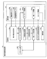
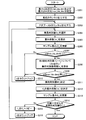
- FIG. 1 is a diagram showing an outline of a subject identification method according to the present invention.
- FIG. 2 is a block diagram illustrating the configuration of the face image identification apparatus according to the present embodiment.
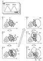
- FIG. 3 is a diagram showing an outline of the subset determination process.
- FIG. 4 is a diagram illustrating an example of leaf node information.
- FIG. 5 is a diagram illustrating an example of a branching plan.
- FIG. 6 is a diagram illustrating a combination of a subset and a discriminator and an acceptance rate.
- FIG. 7 is a diagram illustrating an example of all node information.
- FIG. 8 is a diagram showing an outline of the LDAArray stage number determination process.
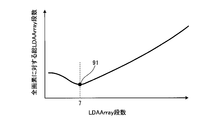
- FIG. 9 is a diagram illustrating a relationship between a predetermined number of LDAArray stages and the total number of LDAArray stages for all pixels.
- FIG. 10 is a diagram showing the face image detection capability.
- FIG. 11 is a flowchart illustrating a processing procedure of leaf node determination processing.
- FIG. 12 is a flowchart illustrating a processing procedure of all node determination processing.
- FIG. 13 is a diagram showing an outline of the LDAArray method.
- FIG. 14 is a block diagram showing the configuration of the LDAArray unit.
- FIG. 15 is a diagram illustrating processing for acquiring a feature amount from a sample image.
- FIG. 16 is a diagram illustrating a process of calculating an aggregate discriminator candidate.
- FIG. 17 is a diagram illustrating a process for calculating an offset of an aggregation discriminator candidate.
- FIG. 18 is a diagram illustrating an example of the aggregate discriminator selection.
- FIG. 19 is a diagram illustrating a process for deriving an aggregation classifier.
- FIG. 20 is a flowchart illustrating a processing procedure executed by the LDAArray unit.
- FIG. 21 is a flowchart showing the processing procedure of the aggregate discriminator determination process.
- FIG. 22 is a diagram showing an outline of the AdaBoost method.
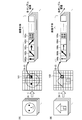
- FIG. 1 is a diagram showing an outline of a subject identification method according to the present invention. Note that (A) in the figure shows a case where facial images are classified and classified by face orientation, and (B) in the figure shows facial features in categories such as male, female, and race. Each case of classification and identification is shown.
- a “leaf node” that is a terminal node of a tree structure is determined by learning using an “LDAArray method” (FIG. 1A).
- FIG. 1A LDAArray method
- the “LDAArray method” is an improved version of the AdaBoost method that is widely used as a boosting learning method, and a predetermined number of unbinarized discriminators are represented by an LDA (Linear Discriminant Analysis) method.
- An aggregation discriminator is derived by aggregating using, and a final discriminator is derived based on the derived aggregation discriminator. Details of the LDAArray method will be described later with reference to FIG.
- discriminators to be placed at each node of the tree structure are determined in advance by decisions based on experience, and the branching method of the tree structure and the number of stages of the tree structure are also determined within the decisions. It was.
- each node of the tree structure is determined by learning using the above-described class A (face image sample group) and class B (non-face image sample group).
- class A face image sample group
- class B non-face image sample group
- the processing amount required for the identification processing is reduced by deriving the discriminator corresponding to each node while taking into account the processing amount required for learning by the LDAArray method.
- a “leaf node” that is a terminal node of a tree structure is determined (a1, a2, a3, a4 and a5).
- each “leaf node” is associated with a discriminator derived by learning by the LDAArray method and a “subset of class A” by which the discriminator can be separated from class B.
- subset a1 the subset of class A associated with leaf node a1
- subset a2 the subset of class A associated with leaf node a2
- subset a6 the “subset a6” associated with the other node a6 is a direct sum of the “subset a1” and the “subset a2”.
- FIG. 1A shows a case where the face image is classified while being classified according to the orientation of the face.
- the subject identification method according to the present invention can be applied to general identification processing using a tree structure. it can.
- the subject identification method according to the present invention is also applied to the case where the front face features are classified while being classified into categories such as men, women, and races. Can do.
- leaf nodes are determined by learning using the LDAArray method (b1, b2, b3, b4, b5, and b6 in the figure), and combinations of discriminators corresponding to these “leaf nodes” are determined. By evaluating, “other nodes” are determined (b7, b8 and b9 in the figure). The details of the classifier combination evaluation will be described later with reference to FIGS.
- the root node is b9
- the nodes immediately below the root node are b7, b8, b5 and b6, and the nodes directly below b7 are directly below b1, b2, and b8.
- a tree structure having nodes b3 and b4 is generated.
- each face image shown in FIG. 1B is a “class A subset” corresponding to each node.
- the leaf node b2 corresponds to a woman
- the leaf node b4 corresponds to a deeply carved person
- the leaf node b6 corresponds to a person who has received backlight.
- the face image shown in the other node b7 is a direct sum of the face image shown in the leaf node b1 (class A subset b1) and the face image shown in the leaf node b2 (class A subset b2). It becomes.
- the subject identification method according to the present invention generates a tree structure for identification based on learning by the LDAArray method, and determines each node while taking the processing amount into account when generating the tree structure. Therefore, the time required for the identification process can be shortened while improving the identification accuracy of the subject.
- LDAFlow method the subject identification method according to the present invention is referred to as “LDAFlow method”.
- LDAFlow method subject identification method according to the present invention is applied to a face image identification apparatus that identifies a face image and a non-face image (for example, a background image) will be described.
- FIG. 2 is a block diagram illustrating the configuration of the face image identification device 10 according to the present embodiment.
- the face image identification device 10 includes an LDAArray unit 100, a control unit 11, and a storage unit 12.
- control unit 11 identifies the subset determination unit 11a, the leaf node determination unit 11b, the branch plan generation unit 11c, the branch plan determination unit 11d, the other node determination unit 11e, and the LDAArray stage number determination unit 11f. 11g.
- storage part 12 memorize
- the all node information 12c includes leaf node information 12ca corresponding to the leaf node, and other node information 12cb corresponding to another node which is a node other than the leaf node.
- the LDAArray unit 100 is a processing unit that performs learning by the LDAArray method described above.
- the LDAArray unit 100 performs a process of receiving a predetermined face image sample set and a non-face image sample set from the control unit 11 and passing the discriminator derived by learning by the LDAArray method to the control unit 11.
- the configuration and processing contents of the LDAArray unit 100 will be described later with reference to FIG.
- the control unit 11 determines a leaf node in the tree structure for identification, and determines a branch of the tree structure and the number of stages based on the determined leaf node, thereby performing processing for determining all nodes in the tree structure It is. That is, the control unit 11 is a processing unit that performs tree structure determination by the “LDAFlow method”.
- the subset determination unit 11a Based on the face image sample 12a and the non-face image sample 12b read from the storage unit 12, the subset determination unit 11a temporarily determines a subset corresponding to each leaf node of the tree structure and determines a final subset. It is a processing part which performs the process to perform.
- the subset refers to a subset of the face image sample 12a that can be separated from the non-face image sample 12b by each leaf node when the entire face image sample 12a is the entire set.
- the subset determination unit 11a is also a processing unit that updates the subset temporarily determined using the discriminator received from the leaf node determination unit 11b. Then, the subset determination unit 11a repeats the notification of the tentatively determined subset to the leaf node determination unit 11b and the reception of the discriminator from the leaf node determination unit 11b, so that the final corresponding to each leaf node is obtained. A subset is determined and notified to the leaf node determination unit 11b.
- the leaf node determination unit 11b sends the subset (subset of the face image sample 12a) provisionally determined by the subset determination unit 11a and the non-face image sample 12b received via the subset determination unit 11a to the LDAArray unit 100.
- This is a processing unit that performs a process of notifying and receiving the discriminator derived by the LDAArray unit 100 as a temporary decision discriminator.
- the leaf node determination unit 11b notifies the temporarily determined discriminator to the subset determination unit 11a as needed, and repeats the process of receiving the subset determined temporarily by the subset determination unit 11a, thereby corresponding to each leaf node. The process of finally determining the discriminator and the subset to be performed is also performed. Then, the leaf node determination unit 11b registers the finally determined subset and classifier pair in the leaf node information 12ca of the storage unit 12.
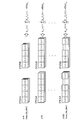
- FIG. 3 is a diagram showing an outline of the subset determination process.
- (A) in the figure shows the sample distribution for each feature amount used to separate class A (a set of face image samples 12a) and class B (a set of non-face image samples 12b).
- (B-1) to (B-6) in the figure show the procedure of the subset determination process, respectively.
- the sample distribution for the selected feature amount is represented as a graph in which class A and class B have overlapping portions.
- the degree of overlap between class A and class B differs for each feature amount.
- the horizontal axis represents the feature amount
- the vertical axis represents the frequency related to the sample distribution.
- the subset determination unit 11a selects a predetermined number of feature amounts from the one with the higher degree of separation between the class A and the class B.
- the subset determining unit 11a selects two feature amounts from the one with the higher degree of separation between class A and class B.
- the face image sample 31 belonging to class A and the non-face image sample 32 belonging to class B are arranged on a two-dimensional plane having two feature amounts as the vertical axis and the horizontal axis, respectively.
- the subset determination unit 11 a selects a sample (most separated sample 33) farthest from the center of gravity position of the non-face image sample 32 distribution from the face image samples 31.
- the subset determining unit 11a selects a predetermined number of face image samples 31 from the closest distance (Euclidean distance) from the most separated sample 33. In addition to A1 (see 34 in the figure). At the stage shown in FIG. 3B-2, the number of members of the subset A1 is four including the most separated sample 33.
- the subset determination unit 11a notifies the LDAArray unit 100 of the temporarily determined subset A1 (the number of members is 4) via the leaf node determination unit 11b. Then, the LDAArray unit 100 performs learning by the LDAArray method using the subset A1 (34) and class B (a set of non-face image samples 12b) as inputs, and determines the discriminator F1 corresponding to the subset A1 (34). To derive.
- the subset determination unit 11a uses the discriminator F1 to set the subset A1 ( The face image samples 31 other than 34) are evaluated.
- the face image sample 31 whose value evaluated by the discriminator F1 is equal to or greater than a predetermined value is added to the subset A1 (34) to generate a new subset A1 (35a).
- the number of members of the subset A1 (35a) is six including the most separated sample 33.
- the subset determining unit 11a notifies the temporarily determined subset A1 (35a) to the LDAArray unit 100 via the leaf node determining unit 11b, and the LDAArray unit 100 includes the subset A1 (35a) and the class B (non-face). Learning is performed by the LDAArray method using a set of image samples 12b as input, and a discriminator F1 corresponding to the subset A1 (35a) is derived.
- the subset determining unit 11a uses the discriminator F1 to evaluate the face image samples 31 other than the subset A1 (35a), and the face image sample whose value evaluated by the discriminator F1 is a predetermined value or more. 31 is added to the subset A1 (35a) to generate a new subset A1 (35b).
- the reconstruction and learning of the subset A1 shown in 34, 35a, and 35b in the figure are repeated, and the subset A1 is determined when the change in the number of members of the subset A1 becomes less than a predetermined threshold. Also, the discriminator F1 corresponding to the subset A1 is determined. The set of the subset A1 and the discriminator F1 determined in this way corresponds to the first leaf node.
- the subset determination unit 11a sets the subset A1 (35b) as shown in (B-4) of FIG. The face image sample 31 belonging to class A is removed.
- each leaf node is determined by repeating the procedures (B-2) to (B-5) in FIG.
- FIG. 3 shows the case where two feature amounts are selected from the one with the greater degree of separation between class A and class B.
- the feature amount to be selected is set to a predetermined number (n) of three or more. Also good.
- the face image sample 31 belonging to class A and the non-face image sample 32 belonging to class B may be arranged on an n-dimensional plane having n feature values as axes.
- the Euclidean distance in the n-dimensional plane may be used.
- the branch plan generation unit 11c is a processing unit that performs processing to generate a branch plan of a tree structure in which only leaf nodes are determined based on the leaf node information 12ca stored in the storage unit 12 by the leaf node determination unit 11b.
- the branch plan generation unit 11c also performs a process of notifying all the generated branch plans to the branch plan determination unit 11d.
- the branch plan generation unit 11c uses all combinations of leaf nodes ( n C 2 to n C i : 2 ⁇ i ⁇ n) as branch plans. Generate and notify all the generated branch plans to the branch plan decision unit 11d.
- the branch plan determination unit 11d is a processing unit that performs processing to narrow down all branch plans received from the branch plan generation unit 11c to one branch plan. Specifically, the branching plan determining unit 11d selects any one part for any one classifier with respect to the subsets (A1 to An) and classifiers (F1 to Fn) included in the leaf node information 12ca. The acceptance rate of class B is calculated for every combination that assumes a set input.
- the branch plan determination unit 11d calculates a representative acceptance rate that represents the group for each group included in each branch plan, and calculates an evaluation value for evaluating each branch plan based on the calculated representative acceptance rate. calculate. Then, the branch plan with the smallest evaluation value is determined as the branch to be used.
- the evaluation value refers to the acceptance rate of class B as the entire branch plan.
- the branch plan generation unit 11c for the group includes all combinations of leaf nodes ( n C 1 to n C i ; 1 ⁇ i ⁇ n) is generated as each branch plan.
- the branching plan determining unit 11d calculates the evaluation value of each branching plan, and determines the branching plan having the smallest evaluation value as a branch under the group. Furthermore, the branching plan determining unit 11d repeats these processes until all the groups are composed of only one leaf node.
- the other node determination unit 11e receives all branches determined from the branch plan determination unit 11d, that is, all nodes other than leaf nodes (other nodes), and determines a subset and a discriminator corresponding to the received other nodes. It is a processing part which performs the process to perform.
- the other node determination unit 11e calculates the direct sum of the subsets corresponding to the leaf nodes in the group. As a subset corresponding to. If the predetermined other node is a group of one leaf node, a subset and a discriminator corresponding to the leaf node are employed as they are.
- the other node determination unit 11e also performs a process of determining a discriminator corresponding to the determined subset. Specifically, the other node determination unit 11e notifies the LDAArray unit 100 of the determined subset. Then, the LDAArray unit 100 performs learning by the LDAArray method using the notified subset and class B (a set of non-face image samples 12b) as inputs, and derives and derives a discriminator corresponding to the subset. The classifier is returned to the other node determination unit 11e.
- the other node determination unit 11e determines a subset and a set of discriminators for all nodes (other nodes) other than the leaf node already determined by the leaf node determination unit 11b.
- the other node determination unit 11e determines a set of subsets and discriminators for all other nodes, the group and the branching relationship of each node are registered in the other node information 12cb.
- the face image sample 12a that does not belong to any subset may belong to the subset that is farthest from class B.
- the face image sample 12a may be deleted.
- FIG. 4 illustrates an example of leaf node information 12ca
- FIG. 5 illustrates an example of a branch plan generated by the branch plan generation unit 11c
- FIG. 6 illustrates a specific example of the branch determination process performed by the branch plan determination unit 11d, and the like.
- An example of the node information 12cb will be described using FIG.
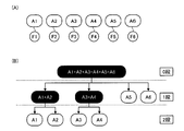
- FIG. 4 is a diagram illustrating an example of the leaf node information 12ca. Note that (A) in the figure shows an example of the leaf node information 12ca, and (B) in the figure shows a branching example using the leaf node information 12ca.
- FIG. 4A shows a case where six leaf nodes are determined by the leaf node determination unit 11b. As shown in FIG. 4A, the subset A1 and the discriminator F1 are determined as the first leaf node, the subset A2 and the discriminator F2 are determined as the second leaf node, and so on. In addition, six leaf nodes have been determined.
- FIG. 4B When six leaf nodes are determined in this way, for example, as shown in FIG. 4B, another node of the tree structure (a node indicated by white letters in the figure) 11e is determined.
- the level corresponding to the root node of the tree structure is referred to as 0 level, the level immediately below the root node as 1 level, and the level immediately below 1 level as 2 levels.
- the first-stage internal node that bundles the second-stage subset A1 and subset A2 is determined, and the second-stage subset A3 and subset A4 are bundled.
- the first internal node is determined.
- the root node of the 0th stage is determined as a node that bundles all the nodes of the first stage.
- the tree structure shown in FIG. 4B is an example, and the number of stages of the tree structure and the way of branching differ depending on the result of the determination process by the other node determination unit 11e.
- the description “A1 + A2” shown in the drawing represents a direct sum of the subset A1 and the subset A2.
- FIG. 5 is a diagram illustrating an example of a branching plan.
- an example of a branch plan generated by the branch plan generation unit 11c when six leaf nodes are determined is shown.
- a node corresponding to the subset A1 is referred to as a node A1.
- the branch plan generator 11c generates a branch plan 1 for branching into a group 1 consisting of node A1, node A2, node A3 and node A4 and a group 2 consisting of node A5 and node A6. To do. Further, a branch plan 2 is generated that branches into a group 1 composed of the nodes A1, A2 and A3, a group 2 composed of the nodes A4 and A5, and a group 3 composed only of the node A6.
- the branch plan generation unit 11c generates all grouping patterns for the six leaf nodes.
- a case where the branch plan generation unit 11c generates m grouping patterns, that is, a case where m branch plans are generated is illustrated.
- FIG. 6 is a diagram showing the relationship between the distribution of the subset and the threshold value of the discriminator and the acceptance rate.
- the acceptance rate in the figure refers to the acceptance rate of the class B image group when the class A threshold obtained by inputting the class A image group to the discriminator Fn is used.
- (A) in the figure shows the relationship between the distribution of the subset and the threshold value of the discriminator
- (B) in the figure shows the acceptance of class B (set of non-face image samples 12b) in each combination. Examples of rates are shown for each.
- 64 indicates a record for the discriminator F1
- 65 similarly indicates a record for the discriminator F2.
- the branching plan determining unit 11d performs all combinations of all subsets An included in the leaf node information 12ca and all discriminators Fn included in the leaf node information 12ca.
- the discriminator F1 and the subset A1 are originally generated as a set for one leaf node, when the subset A1 and the class B are input to the discriminator F1, the class B is selected from the subset A1. It should be able to be separated efficiently (see 61 in the figure).
- the acceptance rate of class B is a low value.
- the broken line shown by 61 in the figure corresponds to a predetermined deviation (for example, 3 ⁇ or 4 ⁇ ) in the class A distribution.
- the ratio of class B distributed on the class A side from the broken line is the acceptance rate of class B.
- the subset A2 is originally generated as a set with the discriminator F2
- when the subset A2 and class B are input to the discriminator F1 compared to the case where the subset A1 is input, Class B cannot be separated efficiently (see 62 in the figure).
- the compatibility between the classifier F1 and each subset is determined.
- the acceptance rate of class B is calculated for each combination of the discriminator and the subset. Based on the acceptance rate, a representative acceptance rate representing each group included in the branch plan is calculated. For example, the representative acceptance rate representing the group 1 shown in the branch plan 2 of FIG. 5 is calculated by the following procedure.
- the acceptance rate of class B when the classifier F1 and the subset A1 are combined is represented as AR (F1, A1).
- AR (F1, A1) 1%.
- the group 1 of the branch plan 2 includes three nodes A1 to A3. For this reason, the total number of combinations of classifiers and subsets is nine (3 ⁇ 3). In this case, the acceptance rates of the nine combinations are AR (F1, A1), AR (F1, A2), AR (F1, A3), AR (F2, A1), AR (F2, A2), AR, respectively. (F2, A3), AR (F3, A1), AR (F3, A2), and AR (F3, A3).
- branch plan determination unit 11d calculates the representative acceptance rate in the same manner for the other groups (group 2 and group 3) of the branch plan 2. Similarly, the branch plan determination unit 11d calculates the representative acceptance rate of the group included in each branch plan for all branch plans (in the case of FIG. 5, branch plan 1 to branch plan m).
- “ ⁇ ” represents the total sum regarding the number of groups, and “ ⁇ ” represents a predetermined adjustment value.
- the branching plan determining unit 11d calculates the evaluation value of each branching plan, and adopts the branching plan having the smallest evaluation value.
- branching plan determining unit 11d repeats the evaluation value calculation process until all the nodes included in each group become one. If all branches are determined, the branch plan determining unit 11d registers all the determined nodes and branch relationships in the all node information 12c of the storage unit 12.
- FIG. 7 is a diagram illustrating an example of all node information 12c.
- the nodes represented by white letters represent the other nodes determined by the branching plan determining unit 11d
- the other nodes represent the leaf nodes determined by the leaf node determining unit 11b. .
- the node (A1 + A2) consisting of a set of the subset (A1 + A2) and the discriminator F ⁇ is determined by the branching plan determining unit 11d as the first stage node.
- the discriminator F ⁇ is derived by learning by the LDAArray method by the LDAArray unit 100 having a subset (A1 + A2) and class B (a set of non-face image samples 12b) as inputs.
- a branch plan deciding unit 11d decides a node (A1 + A2 + A3 + A4 + A5 + A6) consisting of a set of a subset (A1 + A2 + A3 + A4 + A5 + A6) and a discriminator F ⁇ .
- the discriminator F ⁇ is derived by learning by the LDAArray method by the LDAArray unit 100 having a subset (A1 + A2 + A3 + A4 + A5 + A6) and class B (a set of non-face image samples 12b) as inputs.
- the all node information 12c is information including a subset and a discriminator corresponding to all the nodes constituting the tree structure.
- the other node determination unit 11e registers the other node information 12cb in the storage unit 12, the leaf node information 12ca and the other node information 12cb are combined to complete the entire node information 12c. Therefore, the LDA Array stage number determination unit 11f determines the “LDAArray stage number” of the discriminator corresponding to each node.
- the number of LDAArray stages refers to the number of aggregate discriminators (K) included in the discriminator derived by learning by the LDAArray method. Note that, by adjusting the number of LDAArray stages from the viewpoint of reducing the processing amount, it is possible to reduce the amount of calculation as a whole.
- the LDAArray stage number determination unit 11f is a processing unit that performs a process of determining the LDAArray stage number of the discriminator corresponding to each node included in the all node information 12c.
- the LDAArray stage number determination unit 11f determines the number of LDAArray stages of each discriminator so that the total number of LDAArray stages of class B when each discriminator is used is minimized.
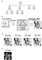
- FIG. 8 is a diagram showing an outline of the LDAArray stage number determination process. Note that (A) in the figure shows the arrangement of the discriminator as a premise for explanation, and (B) to (D) in the figure show the procedure for determining the number of LDAArray stages.
- the classifier F ⁇ is located at the root node, the classifiers F ⁇ , F ⁇ , F5, and F6 are subordinate to the classifier F ⁇ , and the classifiers F1 and F6 are subordinate to the classifier F ⁇ .
- the procedure of the LDAArray stage number determination process when F2 and discriminators F3 and F4 are arranged under the discriminator F ⁇ will be described below.
- the LDAArray stage number determination unit 11f first collates the class B image group with the discriminator F ⁇ , and each pixel of each image is excluded by what number of LDAArray stage numbers. Calculate. Specifically, such a pixel is excluded when the number of pixels to be excluded becomes a predetermined threshold value or less. In the case shown in the figure, the pixel in the upper left corner is in the 5th row, the adjacent pixel is in the 20th row, and the adjacent pixel is in the 30th row. Yes.
- the LDAArray stage number determination unit 11f uses the discriminators under the discriminator F ⁇ for pixels other than the pixels masked in FIG. 8B.
- the number of LDAArray stages to be excluded for each pixel is calculated.
- the number of stages obtained in (C) of FIG. 8 is added to the number of stages obtained in (B) of FIG.
- the number of stages of the second pixel from the upper left corner to the right in FIG. 8B is “20”, and the number of excluded stages when the discriminator F ⁇ is used for such a pixel is “5”.
- the LDAArray stage number determination unit 11f calculates the relationship between the total number of LDAArray stages for each pixel of class B and the predetermined number of LDAArray stages (10 stages in the figure).
- the discriminator F ⁇ and the discriminator F ⁇ pixels that could not be eliminated by a predetermined number of LDAArray stages (10 stages in the figure) are further masked (see FIG. 8D), for example, in the classifier F1. The number of exclusion stages is added.
- the LDAArray stage number determination unit 11f obtains the total number of LDAArray stages corresponding to the predetermined LDAArray stage number for each pixel while changing the predetermined LDAArray stage number from one stage to a predetermined stage number for each discriminator. Then, when the total number of LDAArray stages for each pixel is added for all pixels, the relationship between the predetermined number of LDAArray stages and the total number of LDAArray stages for all pixels is obtained for each discriminator.
- FIG. 9 is a diagram showing the relationship between a predetermined number of LDAArray stages and the total number of LDAArray stages for all pixels.
- the horizontal axis of the graph shown in the figure represents a predetermined number of LDAArray stages, and the vertical axis represents the total number of LDAArray stages for all pixels.
- the LDAArray step number determination unit 11f corresponds to the minimum value 91.
- the number of LDAArray stages is determined as the number of LDAArray stages of the corresponding discriminator. In the case shown in the figure, the number of LDAArray stages is seven.
- the LDAArray stage number determination unit 11f determines the LDAArray stage number for each discriminator included in the all node information 12c, and registers the determined LDAArray stage number in the all node information 12c.
- the identification unit 11g is a processing unit that performs input image discrimination processing using the completed tree structure included in the all-node information 12c, the discriminator arranged at each node of the tree structure, and the number of LDAArray stages of each discriminator. .
- the identification unit 11g uses the completed tree structure (for example, see FIG. 8A) and applies each discriminator from the root node, which is the vertex of the tree structure, to the terminal leaf node. By evaluating, it is determined which node the input image corresponds to. If none of the nodes correspond, the input image is determined to belong to class B (a set of non-face image samples 12b).
- the storage unit 12 is a storage unit configured by a storage device such as a nonvolatile memory or a hard disk drive, and stores a face image sample 12a, a non-face image sample 12b, and all node information 12c.
- the face image sample 12a is a group of face image samples belonging to class A.
- the non-face image sample 12b is a sample group of non-face images (for example, background images) belonging to class B. Since all node information 12c has already been described with reference to FIG. 4 or FIG. 7, description thereof is omitted here.
- FIG. 10 is a diagram showing the face image detection capability.
- the horizontal axis of the graph shown in FIG. 10 indicates the number of cases in which a non-face image is misrecognized as a face image, and the vertical axis indicates the ratio in which the face image is correctly recognized as a face image.
- the graph also shows LDAArray method data and AdaBoost method data, in addition to the LDAFlow method data performed by the face image identification device 10. Note that the number of face images and the number of non-face images used in the graph shown in FIG. 10 are both about 10,000.
- the positive recognition rate (see the solid curve) by the LDAFlow method is different from that of the other methods. It turned out to be higher.
- the graph shown in the figure uses the distribution of two populations of a class A face image group and a class B non-face image group, and the number of non-face images shown on the horizontal axis in the figure is represented by a face.
- a threshold value is set at a position that is erroneously recognized as an image
- a ratio in which the face image is correctly recognized as a face image with the threshold value is plotted in the vertical axis direction.
- the face image is correctly recognized as a face image even if the number of non-face images mistakenly recognized as face images increases. It can be seen that the ability to do is good.
- FIG. 11 is a flowchart illustrating a processing procedure of leaf node determination processing. This figure shows a case where the subset determining unit 11a selects one feature amount in the process of selecting a predetermined number of feature amounts from the one with the greater degree of separation between class A and class B. .
- a counter i is initialized to 1 (step S101), and a feature quantity that most separates class A and class B is selected (step S102). Then, a sample (MAX) that is most separated from class B with respect to the selected feature quantity is extracted from class A (step S103).
- the extracted MAX (most separated sample) and a predetermined number of class A samples within a predetermined distance are added to the subset (Ai) (step S104).
- the discriminator (Fi) is derived by performing learning using the LDAArray method using the subset (Ai) and class B (step S105).
- step S108 it is determined whether or not the change in the number of members of the subset (Ai) is less than the threshold ( ⁇ ) (step S108). If the change is less than the threshold ( ⁇ ) (step S108, Yes), the partial The set (Ai) is confirmed and removed from class A (step S109). On the other hand, when the determination condition of step S108 is not satisfied (step S108, No), the processing after step S105 is repeated.
- step S110 it is determined whether or not the number of samples remaining in the class A is equal to or less than a predetermined number or cannot be separated. If the determination condition of step S110 is satisfied (step S110, Yes), the process ends. To do. On the other hand, when the determination condition of step S110 is not satisfied (step S110, No), the counter i is counted up (step S111), and the processes after step S102 are repeated.
- FIG. 11 shows the case where the subset determining unit 11a selects one feature amount in the process of selecting a predetermined number of feature amounts from the one with the greater degree of separation between class A and class B. Two or more feature amounts may be selected.
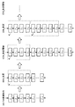
- FIG. 12 is a flowchart illustrating a processing procedure of all node determination processing.
- a subset extracted from class A is described as “class Ak”.
- “n” in the figure represents the number of leaf nodes determined by the leaf node determination unit 11b.
- counters i and k are each initialized to 1 (step S201), and a threshold ( ⁇ ) based on the variance of class Ak when discriminator Fi is used. Is calculated (step S202). Then, the acceptance rate of class B when the threshold value ( ⁇ ) is used is calculated (step S203).
- step S204 it is determined whether or not the counter k is equal to the number of leaf nodes n (step S204). If not equal (step S204, No), the counter k is incremented (step S205), and then step S203. The subsequent processing is repeated. On the other hand, when the determination condition of step S204 is satisfied (step S204, Yes), the process proceeds to step S206.
- step S206 it is determined whether or not the counter i is equal to the number of leaf nodes n (step S206). If the counter i is not equal (step S206, No), the counter i is counted up (step S207), and then step S203. The subsequent processing is repeated. On the other hand, when the determination condition of step S206 is satisfied (step S206, Yes), the process proceeds to step S208.
- the branch plan generation unit 11c generates each branch plan (step S208), and the branch plan determination unit 11d calculates a class B acceptance rate for each group included in each branch plan (step S209). Subsequently, the branching plan determining unit 11d calculates an evaluation value of each branching plan (step S210), and determines a branching plan having the smallest evaluation value as a new stage in the tree structure (step S211).
- step S212 it is determined whether or not the number of members of all the groups has reached 1 until the determined level (level in the tree structure) (step S212). If the number of members has all become 1 (step S212, Yes). ), The process is terminated. On the other hand, when the determination condition of step S212 is not satisfied (step S212, No), the processing after step S208 is repeated.
- the subset determination unit selects a predetermined number of feature amounts used for separating the subject image sample and the non-subject image sample from the one with the higher degree of separation between both samples, For the selected feature amount, the subject image sample that is most separated from the non-subject image sample is selected as the most separated sample, and a subset including the selected most separated sample is extracted from the subject image sample and the subset. And the leaf node determination unit determines a subset by expanding the subset based on the discriminator, and the determined subset is determined as a subject image sample. Subsets obtained by repeating feature selection, selection of most separated samples, and subset determination To constitute a face image identification apparatus to determine each and a set of classifiers corresponding to the subset as a leaf node.
- the above-described LDAFlow method can be applied not only to the identification of a face image but also to image identification such as banknote identification and currency identification.
- FIG. 22 is a diagram showing an outline of the AdaBoost method.
- the AdaBoost method is a learning method for deriving a final discriminator having a high correct answer rate by combining a large number of binarized discriminators that output binarized discrimination results such as YES / NO and positive / negative based on the learning results. It is.
- the classifiers to be combined are weak classifiers (hereinafter referred to as “weak classifiers”) whose correct answer rate slightly exceeds 50%. That is, in the AdaBoost method, a final discriminator with a high correct answer rate is derived by combining a number of weak discriminators with a low correct answer rate.
- the function sign () is a binarization function that is +1 if the value in the parentheses is 0 or more and -1 if the value is less than 0.
- the discriminator h s (x) is a binarization discriminator that takes a value of ⁇ 1 or +1. If it is determined as class B, it takes a value of -1.
- the discriminators h s (x) shown in the equation (1-1) are selected one by one in one learning, and the weighting coefficient ⁇ s corresponding to the selected discriminator h s (x) is selected.
- the final discriminator H (x) is derived by repeating the sequential determination process.
- the Adaboost method will be described in more detail.
- the learning sample is ⁇ (x 1 , y 1 ), ( x 2 , y 2 ),..., (x N , y N ) ⁇ .
- N is the total number of feature quantities to be discriminated.
- D s (i) is a sample weight when the s-th learning is performed on the i-th learning sample
- the discriminator corresponding to each feature quantity x i is h s (x i ) and the weighting coefficient of each discriminator is ⁇ s
- each formula used in the Adaboost method is It becomes.
- the error rate for each discriminator h s (for example, the probability of misclassifying a sample of class A as class B) ⁇ s is calculated using equation (2-1).
- the learning sample distribution for each discriminator h s is shown in (1) of the figure, as shown in (4) of the figure. It will be different from the distribution. Then, the number of learning times s is counted up, the distribution shown in (1) in the figure is updated with the distribution calculated in (4) in the figure, and then the processes after (2) in the figure are repeated.
- the equation (2-3) represents the next learning sample weight so that the best discriminator selected in (2) in the figure becomes a discriminator having an error rate of 0.5 in the next learning. It shows that D s + 1 is determined. In other words, the process of selecting the next best classifier is performed using the learning sample weight that the best classifier is not good at.
- the AdaBoost method repeats learning to perform selection of the discriminator and optimization of the weight coefficient of each discriminator, and finally, a final discriminator having a high correct answer rate can be derived.
- the discriminator h s (x) selected by the Adaboost method is a binarization discriminator, and finally the value held in the discriminator is 2 Output after converting to a value. That is, there is a problem in that a decision branch accompanying binary conversion is required, and the amount of calculation is increased.
- the RealBoost method uses a multi-value discriminator, so it is possible to avoid the problem of increasing the amount of computation due to the decision branch that occurs in the Adaboost method, but for each of the multi-values held by the multi-value discriminator. Since it is necessary to hold the corresponding weighting coefficient, there is a problem that the memory usage increases.
- the “LDAArray method” was devised, which avoids the problem of increased computational complexity due to decision branching and improves the identification accuracy without requiring a large memory as in the real boost method. Below, the outline
- FIG. 13 is a diagram showing an outline of the LDAArray method. Note that (A) in the figure shows an outline of the Adaboost method described with reference to FIG. 10, and (B) in the figure shows an outline of the LDAArray method. Also, the h i the binary discriminator shown in the figure (A), f i shown in the same figure (B) is a function before the h i is binarized by a predetermined threshold value Each unbinarized discriminator is shown.
- the discriminator having the smallest error rate is determined as h 1 in the first learning (see (A-1) in FIG. 13). Then, the weighting factor of h 1 is determined (see (A-2) in the figure). In the next learning, the sample for each sample is set so that h 1 becomes a discriminator having an error rate of 0.5. The weight is updated (see (A-3) in the figure).
- the final discriminator is derived by repeating selection of the discriminator, determination of the weight coefficient for the selected discriminator, and update of the sample weight.
- an aggregation discriminator is derived by aggregating a predetermined number of unbinarized discriminators fi using an LDA (Linear Discriminant Analysis) method,
- LDA Linear Discriminant Analysis
- the unbinarized discriminators are aggregated according to a predetermined procedure (see (B-1) in the figure), and the aggregate discriminators are derived using LDA (see (B-2) in the figure). ). Further, the weight coefficient of the derived aggregation discriminator is determined (see (B-3) in the figure), and the sample weight for each sample is updated (see (B-4) in the figure).
- the selection of the aggregate classifier, the determination of the weighting coefficient for the selected aggregate classifier, and the update of the sample weight are repeated to derive one final classifier.
- a predetermined number of unbinarized discriminators are linearly combined, so that it is possible to reduce the amount of calculation involved in the discrimination processing.
- wasteful decision branch (h i shown in FIG. 13 (A) is always (Decision branch accompanying binary conversion to be performed) can be reduced.
- the discrimination accuracy can be improved.
- FIG. 14 is a block diagram showing the configuration of the LDAArray unit 100.
- the LDAArray unit 100 includes a control unit 111 and a storage unit 112.
- the control unit 111 further includes an Adaboost processing unit 111a, an aggregate discriminator derivation unit 111b, an aggregate weight coefficient determination unit 111c, a sample weight update unit 111d, and a final discriminator determination unit 111e.
- the storage unit 112 stores a face image sample 112a, a non-face image sample 112b, an aggregate discriminator candidate 112c, an aggregate discriminator 112d, and an aggregate weight coefficient 112e.
- the LDAArray unit 100 includes the control unit 111 and the storage unit 112, each processing unit in the control unit 111 is arranged in the control unit 11 shown in FIG.
- Each information stored in the storage unit 112 may be stored in the storage unit 12 illustrated in FIG.
- the face image sample 112a shown in FIG. 14 is the same as the face image sample 12a shown in FIG. 2, and the non-face image sample 112b shown in FIG. 14 and the non-face image sample 12b shown in FIG. May be the same.
- the control unit 111 is a processing unit that performs processing for deriving a final discriminator by learning using the above-described LDAArray method.
- the Adaboost processing unit 111a is a processing unit that performs processing for executing the Adaboost method already described with reference to FIG. Further, the AdaBoost processing unit 111a repeats learning using the face image sample 112a and the non-face image sample 112b read from the storage unit 112 as samples, and collectively discriminates a set of the selected binarization discriminator and the determined weight coefficient. The processing to be passed to the container derivation unit 111b is also performed.
- the AdaBoost processing unit 111a updates the sample weight D s (see FIG. 22) with the received sample weight. Subsequently, the Adaboost processing unit 111a starts the selection of the binarization discriminator from the beginning. That is, after the learning frequency s shown in FIG. 22 is set to 1, the binarization discriminator selection process and the like are repeated.
- FIG. 15 is a diagram illustrating processing for acquiring a feature amount from a sample image.
- (A) in the figure shows a flow of processing for acquiring a feature amount from a face image
- (B) in the same drawing shows a flow of processing for acquiring a feature amount from a non-face image such as a background image. Respectively. Also, it is assumed that the size of each face image and each non-face image shown in the figure has been adjusted by a prior enlargement / reduction process.
- the face image is divided into blocks of a predetermined size (see (A-1) of the figure), and for each block, the edge direction, its strength (thickness), and overall strength (See (A-2) in the figure).
- feature quantities such as an upward edge strength 162a, an upper right edge strength 162b, a right edge strength 162c, a right lower edge strength 162d, and an overall strength 162e of the block 161 are extracted.
- the thickness of the arrows shown at 162a to 162e represents the strength.
- 162a to 162e shown in the figure are examples of feature amounts, and the types of feature amounts are not limited.
- the face image sample 112a is obtained by performing the same process on other face images.
- the non-face image is divided into blocks similar to the face image (see (B-1) of the figure), and the same procedure as the face image is performed for each block.
- feature amounts such as an upward edge strength 164a, an upper right edge strength 164b, a right edge strength 164c, a right lower edge strength 164d, and an overall strength 164e of the block 163 are extracted. Is done.
- the feature values for one non-face image are aligned.
- the non-face image sample 112b is obtained by performing the same process on other non-face images.
- the aggregation discriminator derivation unit 111b is a processing unit that performs processing for deriving the aggregation discriminator 112d in the LDAArray method described above. Specifically, the aggregate discriminator deriving unit 111b, when a predetermined number of binarization discriminators are selected by the Adaboost processing unit 111a, sets a combination of the selected binarization discriminator and the determined weight coefficient. Is a processing unit that performs processing for deriving an aggregate discriminator by combining these binarization discriminators by LDA.
- the aggregate discriminator derivation unit 111b derives an aggregate discriminator candidate 112c, which is an aggregate discriminator candidate, in accordance with the number of binarized discriminators, and one aggregate discriminator among the derived aggregate discriminator candidates 112c. A process for determining the discriminator 112d is also performed.
- the LDAArray method will be described using each mathematical expression. Assuming that the aggregation counter representing the number of times of deriving the aggregation discriminator is t (1 ⁇ t ⁇ T), the feature quantity is x, the aggregation discriminator corresponding to the feature quantity x is K t (x), and the predetermined offset value is th,
- the final discriminator F (x) It is expressed as equation (3-1).
- the function sign () is a binarization function that is +1 if the value in the parentheses is 0 or more and -1 if the value is less than 0. Note that the offset value th can be calculated in the same procedure as the offset t calculation procedure described later with reference to FIG.
- the aggregate discriminator K t (x) Is expressed as in equation (3-2).
- the offset value offset t in the equation (3-2) is not essential, and the final adjustment may be performed with the offset value th in the equation (3-1) after omitting the offset value offset t .
- the relationship between the unbinarized discriminator f s (i) and the binarized discriminator h s (i) is: It is expressed by equation (4). That is, the binarized discriminator h s (i) is obtained by binarizing the unbinarized discriminator f s (i) with the function sign ().
- each aggregation counter t for each aggregation counter t, one aggregation classifier Kt (x) is selected from among a plurality of aggregation classifier candidates, and the weight coefficient ⁇ corresponding to the selected aggregation classifier K t (x) is selected.
- the final discriminator F (x) is derived by repeating the process of sequentially determining t .
- the learning sample is ⁇ (x 1 , y 1 ), ( x 2 , y 2 ),..., (x N , y N ) ⁇ .
- N is the total number of feature quantities to be discriminated.
- L t (i) is a sample weight when the t-th discriminator aggregation is performed on the i-th learning sample
- Expression (5-3) indicates that the aggregation discriminator K t determines the next learning sample weight L t + 1 so that the next discriminator becomes a discriminator having an error rate of 0.5. ing.
- the learning sample weight L t + 1 in the next aggregation is updated, the learning sample weight L t is copied to the learning sample weight D s in the Adaboost process in the LDAarray method. Then, in AdaBoost process will be repeated classifier selection processing learning samples weights D s updated by LDAarray method as an initial value.
- the aggregate discriminator deriving unit 111b has two dimension numbers, that is, a minimum LDA dimension number (min_lda_dim) and a maximum LDA dimension number (max_lda_dim).
- the “dimension number” represents, for example, the number of feature quantities.
- values empirical values derived from the balance between processing time and accuracy can be used.
- an aggregate discriminator candidate 112c is derived by LDA. Then, the derivation process of the aggregate discriminator candidate 112c is repeated until the number of discriminators (s) becomes equal to the maximum number of LDA dimensions (max_lda_dim).
- an aggregate classifier candidate 112c in which two classifiers are aggregated when the minimum number of LDA dimensions (min_lda_dim) is 2 and the maximum number of LDA dimensions (max_lda_dim) is 5, an aggregate classifier candidate 112c in which two classifiers are aggregated, three classifiers are aggregated.
- the aggregate discriminator candidate 112c, the aggregate discriminator candidate 112c in which the four discriminators are aggregated, and the aggregate discriminator candidate 112c in which the five discriminators are aggregated are derived, respectively, and one of the derived aggregate discriminator candidates 112c is derived.
- One aggregation discriminator 112d is selected.
- FIG. 16 is a diagram illustrating a process of calculating an aggregate discriminator candidate.
- the minimum LDA dimension number (min_lda_dim) is 4 and the maximum LDA dimension number (max_lda_dim) is 20.
- the Adaboost processing unit 111a When the number of discriminators (s) selected by the Adaboost processing unit 111a is equal to 4, ie, the minimum number of LDA dimensions (min_lda_dim), the aggregate discriminator deriving unit 111b class A (face image sample 112a) and class B Discriminant analysis by LDA is performed using (non-face image sample 112b). In this way, the aggregate discriminator candidate k t4 (x) when s is 4 is calculated. The same processing is repeated until s is equal to 20, that is, the maximum number of LDA dimensions (max_lda_dim).
- FIG. 17 is a diagram illustrating processing for calculating the offset of the aggregation discriminator candidate 112c.
- 181a, 182a and 183a shown in the figure are graphs representing the probability density distribution of class A (face image sample 112a), and 181b, 182b and 183b shown in the figure are class B (non-face image sample 112b).
- Graphs representing the probability density distributions of are respectively shown.
- the horizontal axis shown in the figure the values of the aggregate classifier candidate (k s), the vertical axis represents probability density shown in the figure, represents respectively.
- offset t4 is calculated as a horizontal axis value corresponding to a point where the class A graph 181a and the class B graph 181b intersect. That is, offset t4 is adjusted so that the probability that a face image is mistakenly recognized as a non-face image is equal to the probability that a non-face image is mistakenly recognized as a face image. Further, the error rate ⁇ t4 is calculated as the area of the hatched portion shown in FIG.
- the aggregate discriminator deriving unit 111b calculates offset tn for each LDA dimension number (s).
- the aggregate discriminator deriving unit 111b calculates the candidate k tn (x) of each aggregate discriminator by performing the processing shown in FIG. 16 and FIG. Subsequently, the aggregate discriminator deriving unit 111b performs a process of selecting one aggregate discriminator 112d from the calculated aggregate discriminator candidates 112c.
- selection processing will be described with reference to FIG.
- FIG. 18 is a diagram illustrating an example of the aggregate discriminator selection.
- the total scan area for a sample image such as class B
- the LDA function is executed only once between the minimum number of LDA dimensions (min_lda_dim) and the maximum number of LDA dimensions (max_lda_dim).
- a graph 191 showing a change in the total scan area) is shown. Further, in the figure, the graph 191 illustrates the case where the minimum value 192 is taken when the LDA dimension number (s) is 6.
- the total scan area is n ⁇ image area + (max_lda_dim ⁇ n) ⁇ (area of area that could not be eliminated by n full scans). Become.
- the relationship between the total scan area calculated in this way and n is, for example, a graph 191.
- the aggregation discriminator deriving unit 111b performs the determination process shown in FIG. 18 using the aggregation discriminator candidate 112c corresponding to the aggregation counter t, and the LDA dimension number (s) candidate that minimizes the total scan area.
- k tn is selected as the aggregate discriminator K t .
- FIG. 18 shows the case where the candidate k tn having the LDA dimension number (s) that minimizes the total scan area is selected as the aggregate discriminator K t , but the LDA dimension number (s) is fixed. It is good. By doing so, since the processing load of the LDA processing does not change depending on the aggregation counter t, parallel processing becomes possible. Therefore, the processing time can be shortened.
- aggregate weight coefficient determination unit 111 c when the aggregate classifier deriving portion 111b has derived the aggregate classifier K t, and determines the weighting factor for the aggregate classifier K t (aggregate weight coefficient alpha t), as an aggregate weight factor 112e It is a processing unit that performs processing to be stored in the storage unit 112.
- the aggregation weighting coefficient ⁇ t is calculated using the above equation (5-2).
- Sample weight updating unit 111d each learning sample weight L in the next aggregated according to the aggregation weight coefficient alpha t determined by the aggregate classifier K t and aggregate weighting coefficient determining section 111c derived by aggregating discriminator deriving portion 111b This is a processing unit that performs a process of updating t + 1 (see Expression (5-3)). Further, the sample weight updating unit 111d is a learning sample weight L t, is also a processing unit performs a process of copying the learning samples weights D s to be used by the AdaBoost processing unit 111a.
- the aggregation discriminator 112d and the aggregation weighting coefficient 112e corresponding to the aggregation counter t are stored in the storage unit 112 while counting up the aggregation counter t.
- the final discriminator determining unit 111e sets the aggregation counter on condition that the correct answer rate of the final discriminator F using the aggregation discriminator 112d (K t ) and the aggregation weight coefficient 112e ( ⁇ t ) is equal to or greater than a predetermined value. End the loop using t. Note that the final discriminator determining unit 111e ends this loop even when there is no binarization discriminator (h s ) to be aggregated.
- Figure 19 is a diagram showing a process of deriving the aggregate classifier K t.
- the control unit 111 performs LDA candidate (aggregate classifier candidate) extraction (see Fig (A)), to determine the aggregate classifiers K 1 learning first (in the figure (See (B)).
- the storage unit 112 is a storage unit configured by a storage device such as a non-volatile memory or a hard disk drive, and includes a face image sample 112a, a non-face image sample 112b, an aggregation discriminator candidate 112c, an aggregation discriminator 112d, and an aggregation discriminator.
- the weight coefficient 112e is stored. Note that the information stored in the storage unit 112 has already been described in the description of the control unit 111, and thus the description thereof is omitted here.
- FIG. 20 is a flowchart showing a processing procedure executed by the LDAArray unit 100.
- the minimum LDA dimension (min_lda_dim) and the maximum LDA dimension (max_lda_dim) are set (step S301)
- the aggregation counter (t) is set to 1 (step S302)
- the Adaboost counter (s) is set. 1 (step S303). Note that when the discriminator f in FIG. 19 is represented using the aggregation counter (t) and the Adaboost counter (s), ft ⁇ s .
- the Adaboost processing unit 111a selects the best discriminator (h s ) (step S304), calculates the weight coefficient ( ⁇ s ) of the best discriminator (h s ) selected in step S304 (step S305). ), And updates the sample weight (D s ) for each sample (step S306).
- the aggregate discriminator deriving unit 111b determines whether or not the Adaboost counter (s) is equal to or greater than the minimum LDA dimension number (min_lda_dim) (step S307), and the Adaboost counter (s) is the minimum LDA dimension number. When it is less than (min_lda_dim) (No at Step S307), the Adaboost counter (s) is counted up (Step S310), and the processes after Step S304 are repeated.
- step S307 when the Adaboost counter (s) is equal to or greater than the minimum LDA dimension number (min_lda_dim) (step S307, Yes), LDA is performed on the unbinarized discriminators (f 1 to f s ), and the aggregate discriminator. A candidate (k s ) is calculated (step S308).
- step S309 it is determined whether or not the Adaboost counter (s) is equal to the maximum LDA dimension number (max_lda_dim) (step S309). If the Adaboost counter (s) is not equal to the maximum LDA dimension number (max_lda_dim), (No at Step S309), the Adaboost counter (s) is counted up (Step S310), and the processes after Step S304 are repeated.
- AdaBoost counter (s) is equal to the maximum LDA dimensionality (max_lda_dim) (step S309, Yes)
- K t the aggregate classifier
- the aggregation weight coefficient determination unit 111c determines the weight coefficient ( ⁇ t ) of the aggregation discriminator (K t ) (step S312), and the sample weight update unit 111d updates the sample weight (L t ) ( Step S313). Then, the final discriminator determining unit 111e either determines whether the class A and the class B are sufficiently separated based on the discrimination result by the final discriminator (F) or there is no unaggregated discriminator. It is determined whether or not the condition is satisfied (step S314).
- step S314, Yes If the determination condition of step S314 is satisfied (step S314, Yes), the final discriminator (F) is determined and the process ends.
- step S314, No when the determination condition of step S314 is not satisfied (step S314, No), the sample weight (L t ) used by the aggregate discriminator derivation unit 111b is copied to the sample weight (D s ) used by the Adaboost processing unit 111a. (Step S315). Then, the aggregation counter (t) is counted up (step S316), and the processes after step S303 are repeated.
- FIG. 21 is a flowchart showing the processing procedure of the aggregate discriminator determination process.
- the aggregate discriminator deriving unit 111b sets the initial value of the LDA dimension number (s) as the minimum LDA dimension number (min_lda_dim) (step S401), and calculates the total scan area (s ⁇ total area). (Step S402).
- a partial scan total area ((max_lda_dim-s) ⁇ residual area) is calculated (step S404). Then, the total scan area (total scan total area + partial scan total area) is calculated (step S405).
- Step S406 it is determined whether or not s is equal to the maximum number of LDA dimensions (max_lda_dim) (step S406). If s is not equal to the maximum number of LDA dimensions (max_lda_dim) (step S406, No), s is counted. (Step S407), the process after Step S402 is repeated. On the other hand, when s is equal to the maximum number of LDA dimensions (max_lda_dim) (Yes in step S406), the aggregate discriminator candidate (k s ) corresponding to the LDA dimension number (s) having the smallest total scan area is the aggregate discriminator. (K t ) (step S408), and the process is terminated.
- the LDAArray method it is possible to avoid the problem of an increase in the amount of calculation due to the decision branch in the Adaboost method, and to improve the identification accuracy without requiring a large memory as in the real boost method.
- the subject identification method, the subject identification program, and the subject identification device according to the present invention are useful when it is desired to perform processing for identifying a specific subject from a predetermined image with high speed and high accuracy. This is suitable for the case where it is desired to dynamically generate an identification tree structure in which containers are arranged.
Landscapes
- Engineering & Computer Science (AREA)
- Theoretical Computer Science (AREA)
- Physics & Mathematics (AREA)
- General Physics & Mathematics (AREA)
- Multimedia (AREA)
- Human Computer Interaction (AREA)
- Health & Medical Sciences (AREA)
- Oral & Maxillofacial Surgery (AREA)
- General Health & Medical Sciences (AREA)
- Computer Vision & Pattern Recognition (AREA)
- Data Mining & Analysis (AREA)
- Artificial Intelligence (AREA)
- Life Sciences & Earth Sciences (AREA)
- Bioinformatics & Cheminformatics (AREA)
- Bioinformatics & Computational Biology (AREA)
- Evolutionary Biology (AREA)
- Evolutionary Computation (AREA)
- General Engineering & Computer Science (AREA)
- Image Analysis (AREA)
Abstract
部分集合決定部が、被写体画像サンプルと非被写体画像サンプルとの分離に用いる複数の特徴量を両サンプルの分離度が高いほうから所定数だけ選択し、選択された特徴量について、非被写体画像サンプルと最も分離している被写体画像サンプルを最分離サンプルとして選択し、選択された最分離サンプルを含んだ部分集合を被写体画像サンプルから抽出するとともにこの部分集合に対応する判別器をLDAArray法による学習によって導出し、リーフノード決定部が、この判別器に基づいて部分集合を拡張していくことで部分集合を決定し、決定された部分集合を被写体画像サンプルから除去したうえで、特徴量選択、最分離サンプル選択および部分集合決定を繰り返すことで得られた部分集合およびこの部分集合に対応する判別器の組をリーフノードとしてそれぞれ決定するように顔画像識別装置を構成する。
Description
本発明は、木構造の各ノードにそれぞれ配置された判別器を用い、木構造の頂点であるルートノードから末端のリーフノードへ向かって判別器を適用していくことで被写体画像と非被写体画像とを識別する被写体識別方法、被写体識別プログラムおよび被写体識別装置に関し、特に、被写体を複数のカテゴリに分類しつつ識別する場合に、被写体の識別精度を向上しつつ、識別処理に要する時間を短縮することができる被写体識別方法、被写体識別プログラムおよび被写体識別装置に関する。
従来から、監視カメラや認証用カメラによって撮像された画像に人の顔が含まれているか否かを自動的に識別する顔画像識別手法が知られている。そして、かかる顔画像識別手法には、部分空間法などの技術が一般的に用いられている。
たとえば、Integral Image法を用いた顔画像識別手法としては、画像中に複数の矩形領域を設定したうえで、各矩形領域に含まれるすべての画素の特徴量を合算することで得られる合算値に基づいて顔画像を検出する技術がある(特許文献1、特許文献2および非特許文献1参照)。
そして、これらの技術を用いて複数の向きの顔を識別するためには、顔の角度を所定角度の範囲ごと(たとえば、30度ごと)に区切り、区切られた範囲にそれぞれ対応するテンプレート(判別器)をあらかじめ作成しておくことが一般的である。
また、作成したテンプレートをあらかじめ木構造に分類し、木構造の頂点であるルートノードから、木構造の末端であるリーフノードまでをたどることで、入力された顔画像がどのテンプレートに該当するかを判定する必要がある。
しかしながら、いわゆる決めうちで、所定角度の範囲ごとのテンプレートをあらかじめ作成しておく手法では、顔の角度の区切り方によって被写体識別の識別性能が大きく左右されるという問題がある。また、顔の角度をどのように区切るかは、実験データなどの経験値に基づいて決定されており、顔の角度をどのように区切ると、よりよい識別性能を得られるかは判明していない。
また、複数の顔の向きにそれぞれ対応するテンプレートを木構造に分類する際にも、木構造の段数や、分岐の仕方については、経験値に基づいて決定されており、各テンプレートをどのように配置すれば、よりよい識別性能が得られるかは判明していない。
そして、顔の角度をどのように区切るかによってテンプレートの数は増減し、テンプレートをどのような分岐の木構造に分類するかによって識別時に経由するテンプレートの組合せも変化することから、被写体識別に要する処理時間は変動する。このため、識別性能は十分であるが処理時間がかかりすぎたり、処理時間は十分に短いが識別性能が不十分であったりという問題もあった。
さらに、Integral Image法を用いた顔画像識別手法によって顔画像を検出する場合、顔画像検出処理に要する処理時間を短縮するためには、特徴量合算値の算出対象となる矩形領域の面積を比較的大きく設定する必要がある。しかし、矩形領域の面積を大きくすると、直射日光が顔に当たっている画像などでは、直射日光の影響で特徴量合算値が大きく変動し、顔画像の検出精度が低下してしまう。また、部分空間法を用いて顔画像を検出する場合、部分空間法は演算量が多いので、顔画像検出処理に要する処理時間がかさんでしまう。
これらのことから、正面顔や斜め顔といった複数の顔の向きについて、顔画像の識別精度を向上しつつ、識別処理に要する処理時間を短縮することができる顔画像識別方法、顔画像識別プログラムあるいは顔画像識別装置をいかにして実現するかが大きな課題となっている。
また、かかる課題は、顔画像を顔の向きで分類しつつ識別する場合に限らず、顔の特徴を男性、女性、人種のようなカテゴリに分類しつつ識別する場合についても同様に発生する課題である。そして、かかる課題は、顔画像を識別対象とする場合にのみ発生する課題ではなく、特定の被写体を識別対象とする場合についても同様に発生する課題である。
本発明は、上述した従来技術の課題を解決するためになされたものであり、被写体を複数のカテゴリに分類しつつ識別する場合に、被写体の識別精度を向上しつつ、識別処理に要する時間を短縮することができる被写体識別方法、被写体識別プログラムおよび被写体識別装置を提供することを目的とする。
上述した課題を解決し、目的を達成するために、本発明は、木構造の各ノードにそれぞれ配置された判別器を用い、前記木構造の頂点であるルートノードから末端のリーフノードへ向かって前記判別器を適用していくことで被写体画像と非被写体画像とを識別する被写体識別方法であって、被写体画像サンプルと非被写体画像サンプルとの分離に用いる複数の特徴量を両サンプルの分離度が高いほうから所定数だけ選択する特徴量選択工程と、前記特徴量選択工程によって選択された前記特徴量について、前記非被写体画像サンプルと最も分離している前記被写体画像サンプルを最分離サンプルとして選択する最分離サンプル選択工程と、前記最分離サンプル選択工程によって選択された前記最分離サンプルを含んだ部分集合を前記被写体画像サンプルから抽出するとともに前記部分集合に対応する前記判別器をLDAArray法による学習によって導出し、当該判別器に基づいて前記部分集合を拡張していくことで前記部分集合を決定する部分集合決定工程と、前記部分集合決定工程によって決定された前記部分集合を前記被写体画像サンプルから除去したうえで、前記特徴量選択工程、前記最分離サンプル選択工程および前記部分集合決定工程を繰り返すことで得られた前記部分集合および当該部分集合に対応する前記判別器の組を前記リーフノードとしてそれぞれ決定するリーフノード決定工程とを含んだことを特徴とする。
また、本発明は、上記の発明において、前記部分集合決定工程は、前記最分離サンプルを含んだ前記部分集合を前記被写体画像サンプルから最初に抽出する場合に、当該最分離サンプルからの距離が短いほうから所定数の前記被写体画像サンプルを当該部分集合に含めて抽出することを特徴とする。
また、本発明は、上記の発明において、前記部分集合決定工程は、前記部分集合の変動数が所定の閾値未満となった場合に、前記部分集合の拡張を停止することを特徴とする。
また、本発明は、上記の発明において、前記リーフノード決定工程によって前記リーフノードとしてそれぞれ決定された前記部分集合からなる母集合を所定個数の前記部分集合を含んだノード候補の集合としてあらわした分岐案について、前記分岐案による前記非被写体画像サンプルのアクセプト率を示す評価値を前記分岐案ごとにそれぞれ算出する評価値算出工程と、前記評価値算出工程によって算出された前記評価値が最小となる前記分岐案に含まれる前記ノード候補のそれぞれを前記ルートノード直下のノードとして決定するとともに、前記ノード候補に複数の前記部分集合が含まれる場合には、当該ノード候補に含まれる前記部分集合の個数が1となるまで前記ノードの決定を繰り返すことで、全てのノードを決定する全ノード決定工程とをさらに含んだことを特徴とする。
また、本発明は、上記の発明において、前記評価値算出工程は、前記リーフノード決定工程によって前記リーフノードとしてそれぞれ決定された前記部分集合および当該部分集合に対応する前記判別器について、いずれか1つの前記判別器に対していずれか1つの前記部分集合の入力を仮定したすべての組合せごとに前記非被写体画像サンプルのアクセプト率をそれぞれ算出し、該アクセプト率に基づいて前記分岐案についての前記評価値を算出することを特徴とする。
また、本発明は、上記の発明において、前記評価値算出工程は、前記分岐案に含まれるすべての前記ノード候補ごとに、当該ノード候補に含まれるすべての前記部分集合について最大の前記アクセプト率を当該ノード候補の代表アクセプト率としたうえで、前記分岐案に含まれる前記ノード候補の前記代表アクセプト率に基づいて前記分岐案についての前記評価値を算出することを特徴とする。
また、本発明は、上記の発明において、前記全ノード決定工程は、前記ノードとして決定された前記ノード候補に複数の前記部分集合が含まれる場合には、前記非被写体画像サンプルおよび当該ノード候補に含まれるすべての前記部分集合を入力としたLDAArray法による学習によって当該ノード候補に対応する前記判別器を導出することを特徴とする。
また、本発明は、上記の発明において、前記判別器が前記非被写体画像サンプルを演算する段数が最小となるように当該判別器における前記LDAArray段数を決定するLDAArray段数決定工程をさらに含んだことを特徴とする。
また、本発明は、上記の発明において、前記LDAArray段数決定工程は、前記判別器に対応する前記ノードが配下ノードを有する場合には、当該ノードにおける前記LDAArray段数およびすべての前記配下ノードにおける前記LDAArray段数との総和である総LDAArray段数が最小となるように前記LDAArray段数を決定することを特徴とする。
また、本発明は、木構造の各ノードにそれぞれ配置された判別器を用い、前記木構造の頂点であるルートノードから末端のリーフノードへ向かって前記判別器を適用していくことで被写体画像と非被写体画像とを識別する被写体識別プログラムであって、被写体画像サンプルと非被写体画像サンプルとの分離に用いる複数の特徴量を両サンプルの分離度が高いほうから所定数だけ選択する特徴量選択手順と、前記特徴量選択手順によって選択された前記特徴量について、前記非被写体画像サンプルと最も分離している前記被写体画像サンプルを最分離サンプルとして選択する最分離サンプル選択手順と、前記最分離サンプル選択手順によって選択された前記最分離サンプルを含んだ部分集合を前記被写体画像サンプルから抽出するとともに前記部分集合に対応する前記判別器をLDAArray法による学習によって導出し、当該判別器に基づいて前記部分集合を拡張していくことで前記部分集合を決定する部分集合決定手順と、前記部分集合決定手順によって決定された前記部分集合を前記被写体画像サンプルから除去したうえで、前記特徴量選択手順、前記最分離サンプル選択手順および前記部分集合決定手順を繰り返すことで得られた前記部分集合および当該部分集合に対応する前記判別器の組を前記リーフノードとしてそれぞれ決定するリーフノード決定手順とをコンピュータに実行させることを特徴とする。
また、本発明は、木構造の各ノードにそれぞれ配置された判別器を用い、前記木構造の頂点であるルートノードから末端のリーフノードへ向かって前記判別器を適用していくことで被写体画像と非被写体画像とを識別する被写体識別装置であって、被写体画像サンプルと非被写体画像サンプルとの分離に用いる複数の特徴量を両サンプルの分離度が高いほうから所定数だけ選択する特徴量選択手段と、前記特徴量選択手段によって選択された前記特徴量について、前記非被写体画像サンプルと最も分離している前記被写体画像サンプルを最分離サンプルとして選択する最分離サンプル選択手段と、前記最分離サンプル選択手段によって選択された前記最分離サンプルを含んだ部分集合を前記被写体画像サンプルから抽出するとともに前記部分集合に対応する前記判別器をLDAArray法による学習によって導出し、当該判別器に基づいて前記部分集合を拡張していくことで前記部分集合を決定する部分集合決定手段と、前記部分集合決定手段によって決定された前記部分集合を前記被写体画像サンプルから除去したうえで、前記特徴量選択手段、前記最分離サンプル選択手段および前記部分集合決定手段を繰り返すことで得られた前記部分集合および当該部分集合に対応する前記判別器の組を前記リーフノードとしてそれぞれ決定するリーフノード決定手段とを備えたことを特徴とする。
本発明によれば、被写体画像サンプルと非被写体画像サンプルとの分離に用いる複数の特徴量を両サンプルの分離度が高いほうから所定数だけ選択し、選択された特徴量について、非被写体画像サンプルと最も分離している被写体画像サンプルを最分離サンプルとして選択し、選択された最分離サンプルを含んだ部分集合を被写体画像サンプルから抽出するとともにこの部分集合に対応する判別器をLDAArray法による学習によって導出し、この判別器に基づいて部分集合を拡張していくことで部分集合を決定し、決定された部分集合を被写体画像サンプルから除去したうえで、特徴量選択、最分離サンプル選択および部分集合決定を繰り返すことで得られた部分集合およびこの部分集合に対応する判別器の組をリーフノードとしてそれぞれ決定することとしたので、学習によって識別用木構造を動的に生成するので、被写体の識別精度を向上しつつ、識別処理に要する時間を短縮することができるという効果を奏する。
また、本発明によれば、最分離サンプルを含んだ部分集合を被写体画像サンプルから最初に抽出する場合に、最分離サンプルからの距離が短いほうから所定数の被写体画像サンプルを部分集合に含めて抽出することとしたので、部分集合の初期メンバを簡便な処理で決定することができるという効果を奏する。
また、本発明によれば、部分集合の変動数が所定の閾値未満となった場合に、部分集合の拡張を停止することとしたので、部分集合のメンバ数の変動収束を検出することで、部分集合の拡張停止を適切なタイミングで行うことができるという効果を奏する。
また、本発明によれば、リーフノードとしてそれぞれ決定された部分集合からなる母集合を所定個数の部分集合を含んだノード候補の集合としてあらわした分岐案について、分岐案による非被写体画像サンプルのアクセプト率を示す評価値を分岐案ごとにそれぞれ算出し、算出された評価値が最小となる分岐案に含まれるノード候補のそれぞれをルートノード直下のノードとして決定するとともに、ノード候補に複数の部分集合が含まれる場合には、このノード候補に含まれる部分集合の個数が1となるまでノードの決定を繰り返すことで、全てのノードを決定することとしたので、識別用木構造の全ノードを動的に決定することができるという効果を奏する。
また、本発明によれば、リーフノードとしてそれぞれ決定された部分集合およびこの部分集合に対応する判別器について、いずれか1つの判別器に対していずれか1つの部分集合の入力を仮定したすべての組合せごとに非被写体画像サンプルのアクセプト率をそれぞれ算出し、算出したアクセプト率に基づいて分岐案についての評価値を算出することとしたので、各分岐案の精度および処理量を加味した評価値を用いることで、適切な分岐案を選択することができるという効果を奏する。
また、本発明によれば、分岐案に含まれるすべてのノード候補ごとに、ノード候補に含まれるすべての部分集合について最大のアクセプト率をこのノード候補の代表アクセプト率としたうえで、分岐案に含まれるノード候補の代表アクセプト率に基づいて分岐案についての評価値を算出することとしたので、ノード候補ごとの代表アクセプト率に基づいて分岐案の評価値を算出することで、適切な分岐案を選択することができるという効果を奏する。
また、本発明によれば、ノードとして決定されたノード候補に複数の部分集合が含まれる場合には、非被写体画像サンプルおよびこのノード候補に含まれるすべての部分集合を入力としたLDAArray法による学習によってこのノード候補に対応する判別器を導出することとしたので、リーフノード以外の全ノードについて適切な判別器を導出することができるという効果を奏する。
また、本発明によれば、判別器が非被写体画像サンプルを演算する段数が最小となるようにこの判別器におけるLDAArray段数を決定することとしたので、各判別器の処理量を抑制することによって、識別処理全体としての処理時間を低減することができるという効果を奏する。
また、本発明によれば、判別器に対応するノードが配下ノードを有する場合には、このノードにおけるLDAArray段数およびすべての配下ノードにおけるLDAArray段数との総和である総LDAArray段数が最小となるようにLDAArray段数を決定することとしたので、各ノードに対応する判別器の処理量を適切に見積もることで、適切なLDAArray段数を決定することができるという効果を奏する。
10 顔画像識別装置
11 制御部
11a 部分集合決定部
11b リーフノード決定部
11c 分岐案生成部
11d 分岐案決定部
11e 他ノード決定部
11f LDAArray段数決定部
11g 識別部
12 記憶部
12a 顔画像サンプル
12b 非顔画像サンプル
12c 全ノード情報
12ca リーフノード情報
12cb 他ノード情報
100 LDAArray部
111 制御部
111a アダブースト処理部
111b 集約判別器導出部
111c 集約重み係数決定部
111d サンプル重み更新部
111e 最終判別器決定部
112 記憶部
112a 顔画像サンプル
112b 非顔画像サンプル
112c 集約判別器候補
112d 集約判別器
112e 集約重み係数
11 制御部
11a 部分集合決定部
11b リーフノード決定部
11c 分岐案生成部
11d 分岐案決定部
11e 他ノード決定部
11f LDAArray段数決定部
11g 識別部
12 記憶部
12a 顔画像サンプル
12b 非顔画像サンプル
12c 全ノード情報
12ca リーフノード情報
12cb 他ノード情報
100 LDAArray部
111 制御部
111a アダブースト処理部
111b 集約判別器導出部
111c 集約重み係数決定部
111d サンプル重み更新部
111e 最終判別器決定部
112 記憶部
112a 顔画像サンプル
112b 非顔画像サンプル
112c 集約判別器候補
112d 集約判別器
112e 集約重み係数
以下に、添付図面を参照して、本発明に係る被写体識別手法の好適な実施例を詳細に説明する。なお、以下では、本発明に係る被写体識別手法の概要について図1を用いて説明した後に、本発明に係る被写体識別手法を適用した顔画像識別装置についての実施例を説明する。また、以下では、識別対象とする被写体を、顔画像とした場合について説明することとする。
図1は、本発明に係る被写体識別手法の概要を示す図である。なお、同図の(A)には、顔画像を顔の向きで分類しつつ識別する場合について、同図の(B)には、顔の特徴を男性、女性、人種のようなカテゴリに分類しつつ識別する場合について、それぞれ示している。
図1の(A)に示したように、本発明に係る被写体識別手法では、木構造(ツリー構造)の末端ノードである「リーフノード」を、「LDAArray法」による学習によって決定し(同図の(A-1)参照)、決定した「リーフノード」に基づいて木構造の各分岐である「内部ノード」と、木構造の頂点である「ルートノード」とを決定していくことで(同図の(A-2)参照)、判別用木構造を動的に生成する点に主たる特徴がある。
ここで、「LDAArray法」とは、ブースティング学習手法として広く用いられているアダブースト(AdaBoost)手法を、改良した手法であり、所定個数の未2値化判別器をLDA(Linear Discriminant Analysis)法を用いて集約することで集約判別器を導出し、導出した集約判別器に基づいて最終判別器を導出する。なお、LDAArray法の詳細については、図13以降を用いて後述することとする。
従来、判別用木構造(ツリー構造)の各ノード(ルートノード、内部ノードあるいはリーフノード)に配置された判別器を用いて顔画像の識別を行う場合、どのような判別器をどのノードに配置するかは、経験に基づいた、いわゆる、決めうちで行われていた。
すなわち、従来は、経験に基づいた決めうちによって、木構造の各ノードに配置する判別器をあらかじめ決定しており、木構造の分岐の仕方や木構造の段数についても、決めうちで決定していた。
このため、識別対象とする顔画像のサンプル群をクラスA、排除対象とする非顔画像のサンプル群をクラスBとした場合に、従来は、排除対象であるクラスBの排除率が十分に高くないという問題があった。これは、あらかじめ決めうちで決定された木構造が、クラスAとクラスBとを分離するための最適な木構造となっていなかったため、言い換えると、木構造が、実際のクラスAおよびクラスBのサンプル分布を反映していなかったため、と考えられる。
そこで、本発明に係る被写体識別手法では、上記したクラスA(顔画像サンプル群)およびクラスB(非顔画像サンプル群)を用いた学習によって木構造の各ノードを決定することとした。そして、かかる学習には、上記したLDAArray法を用いることで、各ノードに対応付けられる各判別器の判別精度を高めるとともに、最終的な木構造自体によるクラスBの排除率を高めることとした。
さらに、本発明に係る被写体識別手法では、LDAArray法による学習に要する処理量を加味しつつ、各ノードに対応する判別器を導出することで、識別処理に要する処理量を削減することとした。
具体的には、本発明に係る被写体識別手法は、図1の(A)に示したように、まず、木構造の末端ノードとなる「リーフノード」を決定する(同図のa1、a2、a3、a4およびa5)。ここで、各「リーフノード」には、LDAArray法による学習によってそれぞれ導出された判別器と、かかる判別器がクラスBから分離できる「クラスAの部分集合」とが対応付けられる。
そして、決定された「リーフノード」をどのように組み合わせるべきかについて、識別精度および処理量の双方を評価することで、「リーフノード」以外の「他ノード(内部ノードおよびルートノード)」を決定していく(同図のa6、a7、a8およびa9)。すなわち、木構造の段数や分岐の仕方は、あらかじめ定められておらず、「リーフノード」や「他ノード」の決定結果によってそれぞれ異なることとなる。
なお、リーフノードa1に対応付けられた「クラスAの部分集合」を「部分集合a1」、リーフノードa2に対応付けられたクラスAの部分集合を「部分集合a2」のように呼ぶこととすると、他ノードa6に対応付けられる「部分集合a6」は、「部分集合a1」と「部分集合a2」との直和となる。
ところで、図1の(A)では、顔画像を顔の向きで分類しつつ識別する場合を示したが、本発明に係る被写体識別手法は、木構造を用いた識別処理全般に適用することができる。たとえば、図1の(B)に示したように、正面顔の特徴を男性、女性、人種のようなカテゴリに分類しつつ識別する場合にも、本発明に係る被写体識別手法を適用することができる。
具体的には、LDAArray法による学習によって、「リーフノード」を決定し(同図のb1、b2、b3、b4、b5およびb6)、これらの「リーフノード」にそれぞれ対応する判別器の組み合わせを評価することで、「他ノード」を決定する(同図のb7、b8およびb9)。なお、判別器の組合せ評価の詳細については、図5および図6を用いて後述する。
このようにすることで、図1の(B)に示したように、ルートノードがb9、ルートノードの直下ノードがb7、b8、b5およびb6、b7の直下ノードがb1およびb2、b8の直下ノードがb3およびb4である木構造が生成されることになる。
ここで、図1の(B)に示した各顔画像は、各ノードに対応する「クラスAの部分集合」である。たとえば、リーフノードb2は女性に、リーフノードb4は彫りが深い人物に、リーフノードb6は逆光を受けた人物に、それぞれ対応していると考えられる。また、他ノードb7に示した顔画像は、リーフノードb1に示した顔画像(クラスAの部分集合b1)と、リーフノードb2に示した顔画像(クラスAの部分集合b2)との直和となる。
このように、本発明に係る被写体識別手法は、LDAArray法による学習に基づいて識別用の木構造を生成するとともに、木構造の生成においては処理量を加味しつつ各ノードを決定することとしたので、被写体の識別精度を向上しつつ、識別処理に要する時間を短縮することができる。また、以下では、本発明に係る被写体識別手法を、「LDAFlow法」と呼ぶこととする。
以下では、本発明に係る被写体識別手法(LDAFlow法)を、顔画像と非顔画像(たとえば、背景画像)との識別を行う顔画像識別装置に適用した場合について説明する。
図2は、本実施例に係る顔画像識別装置10の構成を示すブロック図である。同図に示すように、顔画像識別装置10は、LDAArray部100と、制御部11と、記憶部12とを備えている。
また、制御部11は、部分集合決定部11aと、リーフノード決定部11bと、分岐案生成部11cと、分岐案決定部11dと、他ノード決定部11eと、LDAArray段数決定部11fと、識別部11gとをさらに備えている。そして、記憶部12は、顔画像サンプル12aと、非顔画像サンプル12bと、全ノード情報12cとを記憶する。ここで、全ノード情報12cは、リーフノードに対応するリーフノード情報12caと、リーフノード以外のノードである他ノードに対応する他ノード情報12cbとを含む。
LDAArray部100は、上述したLDAArray法による学習を実行する処理部である。ここで、LDAArray部100は、所定の顔画像サンプル集合および非顔画像サンプル集合を制御部11から受け取り、LDAArray法による学習によって導出された判別器を制御部11へ渡す処理を行う。なお、このLDAArray部100の構成および処理内容については、図13以降を用いて後述することとする。
制御部11は、識別用の木構造におけるリーフノードを決定するとともに、決定したリーフノードに基づいて木構造の分岐や段数を決定することで、木構造における全ノードを決定する処理を行う処理部である。すなわち、制御部11は、「LDAFlow法」による木構造決定を行う処理部である。
部分集合決定部11aは、記憶部12から読み出した顔画像サンプル12aおよび非顔画像サンプル12bに基づき、木構造のリーフノードにそれぞれ対応する部分集合を仮決定するとともに、最終的な部分集合を決定する処理を行う処理部である。ここで、部分集合とは、顔画像サンプル12a全体を全体集合とした場合に、各リーフノードが、非顔画像サンプル12bから分離可能な顔画像サンプル12aの部分集合を指す。
また、部分集合決定部11aは、リーフノード決定部11bから受け取った判別器を用いて仮決定した部分集合の更新を行う処理部でもある。そして、部分集合決定部11aは、リーフノード決定部11bに対する仮決定した部分集合の通知と、リーフノード決定部11bからの判別器の受け取りとを繰り返すことで、各リーフノードに対応する最終的な部分集合を決定し、リーフノード決定部11bへ通知する。
リーフノード決定部11bは、部分集合決定部11aが仮決定した部分集合(顔画像サンプル12aの部分集合)と、部分集合決定部11a経由で受け取った非顔画像サンプル12bとをLDAArray部100部へ通知し、LDAArray部100が導出した判別器を仮決定判別器として受け取る処理を行う処理部である。
また、リーフノード決定部11bは、仮決定した判別器を部分集合決定部11aへ随時通知するとともに、部分集合決定部11aが仮決定した部分集合を受け取る処理を繰り返すことで、各リーフノードに対応する判別器および部分集合を最終的に決定する処理を併せて行う。そして、リーフノード決定部11bは、最終決定した部分集合および判別器の組を記憶部12のリーフノード情報12caに対して登録する。
ここで、部分集合決定部11aが行う部分集合決定処理の概要について図3を用いて説明しておく。図3は、部分集合決定処理の概要を示す図である。なお、同図の(A)には、クラスA(顔画像サンプル12aの集合)と、クラスB(非顔画像サンプル12bの集合)とを分離するために用いる特徴量ごとのサンプル分布を、同図の(B―1)~(B-6)には、部分集合決定処理の手順を、それぞれ示している。
図3の(A)に示したように、所定の特徴量を選択した場合、選択した特徴量についてのサンプル分布は、クラスAとクラスBとが重複部分をもつグラフとしてあらわされる。そして、クラスAとクラスBとの重複具合は、特徴量ごとにそれぞれ異なる。なお、図3の(A)における横軸は特徴量を、縦軸はサンプル分布に関する度数を、それぞれあらわしている。
そこで、部分集合決定部11aは、クラスAとクラスBとの分離度合いが大きいほうから所定数の特徴量を選択する。なお、以下では、部分集合決定部11aが、クラスAとクラスBとの分離度合いが大きいほうから2つの特徴量を選択した場合について説明する。また、以下では、2つの特徴量をそれぞれ縦軸および横軸とする2次元平面上に、クラスAに属する顔画像サンプル31およびクラスBに属する非顔画像サンプル32を配置した場合について説明する。
図3の(B-1)に示したように、クラスAに属する顔画像サンプル31を黒丸で、クラスBに属する非顔画像サンプル32を白丸で、それぞれあらわすと、各サンプルの分布図が得られる。ここで、部分集合決定部11aは、非顔画像サンプル32分布の重心位置から最も離れているサンプル(最分離サンプル33)を顔画像サンプル31の中から選択する。
つづいて、図3の(B-2)に示したように、部分集合決定部11aは、最分離サンプル33からの距離(ユークリッド距離)が近いほうから所定数の顔画像サンプル31を、部分集合A1に加える(同図の34参照)。なお、図3の(B-2)に示した段階では、部分集合A1のメンバ数は、最分離サンプル33を含めて4個である。
そして、部分集合決定部11aは、仮に決定した部分集合A1(メンバ数は4個)を、リーフノード決定部11b経由でLDAArray部100へ通知する。そして、LDAArray部100は、部分集合A1(34)とクラスB(非顔画像サンプル12bの集合)とを入力としたLDAArray法による学習を行い、部分集合A1(34)に対応する判別器F1を導出する。
つづいて、図3の(B-3)に示したように、リーフノード決定部11b経由で判別器F1を受け取ったならば、部分集合決定部11aは、判別器F1を用いて部分集合A1(34)以外の顔画像サンプル31を評価する。
そして、判別器F1によって評価された値が所定値以上である顔画像サンプル31を部分集合A1(34)に加え、あらたな部分集合A1(35a)を生成する。なお、図3の(B-3)に示した場合では、部分集合A1(35a)のメンバ数は最分離サンプル33を含めて6個である。
さらに、部分集合決定部11aは、仮決定した部分集合A1(35a)をリーフノード決定部11b経由でLDAArray部100へ通知し、LDAArray部100は、部分集合A1(35a)とクラスB(非顔画像サンプル12bの集合)とを入力としたLDAArray法による学習を行い、部分集合A1(35a)に対応する判別器F1を導出する。
つづいて、部分集合決定部11aは、かかる判別器F1を用いて部分集合A1(35a)以外の顔画像サンプル31を評価し、判別器F1によって評価された値が所定値以上である顔画像サンプル31を部分集合A1(35a)に加え、あらたな部分集合A1(35b)を生成する。
そして、同図の34、35aおよび35bに示した部分集合A1の再構成および学習を繰り返し、部分集合A1のメンバ数の変動が所定の閾値未満となった時点で部分集合A1を確定する。また、部分集合A1に対応する判別器F1についても確定する。なお、このようにして決定された部分集合A1および判別器F1の組が、1つめのリーフノードに対応することになる。
つづいて、部分集合A1(35b)が最終的な部分集合A1として決定されたとすると、部分集合決定部11aは、図3の(B-4)に示したように、部分集合A1(35b)をクラスAに属する顔画像サンプル31から除去する。
そして、図3の(B-5)に示したように、部分集合A1が除去された顔画像サンプル31について、最分離サンプル36の選択、部分集合A2(37a)の仮決定、学習に基づく部分集合A2(37a)の再構成を繰り返し、最終的な部分集合A2(37b)を確定する。また、部分集合A2に対応する判別器F2についても確定する。なお、このようにして決定された部分集合A2および判別器F2の組が、2つめのリーフノードに対応することになる。
つづいて、図3の(B-6)に示したように、部分集合A3についても、部分集合A1および部分集合A2の場合と同様にして再構成を繰り返し(同図の38aおよび38b参照)、最終的な部分集合A3および判別器F3を決定する。以下、図3の(B-2)~(B-5)の手順を繰り返していくことで、各リーフノードを決定していく。
なお、図3では、クラスAとクラスBとの分離度合いが大きいほうから2つの特徴量を選択した場合について示したが、選択する特徴量を3つ以上の所定数(n)とすることとしてもよい。
この場合、n個の特徴量を各軸としたn次元平面上に、クラスAに属する顔画像サンプル31およびクラスBに属する非顔画像サンプル32を配置することとすればよい。そして、サンプル間の距離としては、n次元平面におけるユークリッド距離を用いることとすればよい。
図2の説明に戻り、分岐案生成部11cについて説明する。分岐案生成部11cは、リーフノード決定部11bによって記憶部12に格納されたリーフノード情報12caに基づき、リーフノードのみが決定された木構造の分岐案を生成する処理を行う処理部である。また、この分岐案生成部11cは、生成した全分岐案を、分岐案決定部11dへ通知する処理を併せて行う。
具体的には、決定されたリーフノードがn個である場合、この分岐案生成部11cは、リーフノードの全組合せ(nC2~nCi:2≦i≦n)を各分岐案として生成し、生成した全分岐案を分岐案決定部11dへ通知する。
たとえば、リーフノードが3個(α、βおよびγ)である場合には、分岐案1として「グループA(αおよびβ)、グループB(γのみ)」、分岐案2として「グループA(αおよびγ)、グループB(βのみ)」、分岐案3として「グループA(βおよびγ)、グループB(αのみ)」、分岐案4として「グループA(α、βおよびγ)のみ」のように、4つの分岐案を生成することになる。
分岐案決定部11dは、分岐案生成部11cから受け取った全分岐案を1つの分岐案に絞る処理を行う処理部である。具体的には、分岐案決定部11dは、リーフノード情報12caに含まれる部分集合(A1~An)および判別器(F1~Fn)について、いずれか1つの判別器に対していずれか1つの部分集合の入力を仮定したすべての組合せごとに、クラスBのアクセプト率を算出する。
つづいて、分岐案決定部11dは、各分岐案に含まれるグループごとに、グループを代表する代表アクセプト率を算出し、算出した代表アクセプト率に基づいて各分岐案を評価するための評価値を算出する。そして、評価値が最小となった分岐案を、使用する分岐として決定する。ここで、評価値とは、各分岐案全体としてのクラスBのアクセプト率のことを指す。
なお、分岐案決定部11dが決定した分岐案に含まれるグループが、複数のリーフノードを含む場合には、かかるグループについて、分岐案生成部11cにリーフノードの全組合せ(nC1~nCi;1≦i≦n)を各分岐案として生成させる。
そして、分岐案決定部11dは、各分岐案の評価値算出を行ったうえで、評価値が最小となった分岐案を、かかるグループ配下の分岐として決定する。さらに、分岐案決定部11dは、すべてのグループが1つのリーフノードのみから構成されるようになるまでこれらの処理を繰り返す。
他ノード決定部11eは、分岐案決定部11dから決定されたすべての分岐、すなわち、リーフノード以外のすべてのノード(他ノード)を受け取り、受け取った他ノードに対応する部分集合および判別器を決定する処理を行う処理部である。
具体的には、この他ノード決定部11eは、所定の他ノードが、複数のリーフノードのグループである場合には、グループ内の各リーフノードに対応する部分集合の直和を、かかる他ノードに対応する部分集合として決定する。なお、所定の他ノードが1つのリーフノードのグループである場合には、かかるリーフノードに対応する部分集合および判別器をそのまま採用する。
また、他ノード決定部11eは、決定した部分集合に対応する判別器を決定する処理を併せて行う。具体的には、他ノード決定部11eは、決定した部分集合を、LDAArray部100へ通知する。そして、LDAArray部100は、通知された部分集合とクラスB(非顔画像サンプル12bの集合)とを入力としたLDAArray法による学習を行い、かかる部分集合に対応する判別器を導出し、導出した判別器を他ノード決定部11eへ返す。
このようにして、他ノード決定部11eは、リーフノード決定部11bによって既に決定されているリーフノード以外のすべてのノード(他ノード)について部分集合および判別器の組を決定する。そして、他ノード決定部11eが、すべての他ノードについて部分集合および判別器の組を決定したならば、これらの組および各ノードの分岐関係を他ノード情報12cbに対して登録する。
なお、いずれの部分集合にも属さなかった顔画像サンプル12aについては、最もクラスBから離れる部分集合に所属させることとすればよい。また、目視の結果、明らかに誤ったサンプルだと考えられる場合には、かかる顔画像サンプル12aを削除することとしてもよい。
ここで、リーフノード情報12caの例について図4を、分岐案生成部11cが生成する分岐案の例について図5を、分岐案決定部11dが行う分岐決定処理の具体例について図6を、他ノード情報12cbの例について図7を、それぞれ用いて説明しておく。
まず、リーフノード情報12caの例について図4を用いて説明する。図4は、リーフノード情報12caの例を示す図である。なお、同図の(A)には、リーフノード情報12caの例を、同図の(B)には、リーフノード情報12caを用いた分岐例を、それぞれ示している。
図4の(A)には、リーフノード決定部11bによって6つのリーフノードが決定された場合について示している。図4の(A)に示したように、部分集合A1および判別器F1が1つめのリーフノードとして、部分集合A2および判別器F2が2つめのリーフノードとして、それぞれ決定されており、以下同様に、6つのリーフノードが決定されている。
このように6つのリーフノードが決定された場合、たとえば、図4の(B)に示したように、木構造の他ノード(同図に白抜き文字で示したノード)が、他ノード決定部11eによって決定されていくことになる。ここで、木構造のルートノードに対応する段を0段、ルートノード直下の段を1段、1段の直下の段を2段というように呼ぶこととする。
図4の(B)に示した場合では、2段目の部分集合A1および部分集合A2を束ねる1段目の内部ノードが決定されており、2段目の部分集合A3および部分集合A4を束ねる1段目の内部ノードが決定されている。そして、1段目の全ノードを束ねるノードとして、0段目のルートノードが決定されている。
なお、図4の(B)に示した木構造は、一例であり、木構造の段数および分岐の仕方は、他ノード決定部11eによる決定処理の結果によって異なるものとなる。また、同図に示した「A1+A2」といった記載は、部分集合A1と部分集合A2との直和をあらわしている。
次に、分岐案生成部11cが生成する分岐案の例について図5を用いて説明する。図5は、分岐案の例を示す図である。なお、同図では、6つのリーフノードが決定された場合に(図4の(A)参照)、分岐案生成部11cが生成する分岐案の例を示している。また、以下の説明では、部分集合A1に対応するノードをノードA1と記載することとする。
図5に示したように、分岐案生成部11cは、ノードA1、ノードA2、ノードA3およびノードA4からなるグループ1と、ノードA5およびノードA6からなるグループ2とに分岐させる分岐案1を生成する。また、ノードA1、ノードA2およびノードA3からなるグループ1と、ノードA4およびノードA5からなるグループ2と、ノードA6のみからなるグループ3とに分岐させる分岐案2を生成する。
同様に、分岐案生成部11cは、6つのリーフノードについて、すべてのグループ分けパターンを生成していく。なお、同図では、分岐案生成部11cが、m個のグループ分けパターンを生成した場合、すなわち、m個の分岐案を生成した場合について示している。
次に、分岐案決定部11dが行う分岐決定処理の具体例について図6を用いて説明する。図6は、部分集合の分布と判別器の閾値との関係およびアクセプト率を示す図である。ここで、同図におけるアクセプト率とは、判別器FnにクラスAの画像群を入力することで得られるクラスAの閾値を用いた場合における、クラスBの画像群のアクセプト率のことを指すものとする。
なお、同図の(A)には、部分集合の分布と判別器の閾値との関係を、同図の(B)には、各組合せにおけるクラスB(非顔画像サンプル12bの集合)のアクセプト率の例を、それぞれ示している。また、同図の(B)における64は、判別器F1についてのレコードを、同じく65は、判別器F2についてのレコードを、それぞれ示している。
図6の(A)に示したように、分岐案決定部11dは、リーフノード情報12caに含まれるすべての部分集合Anと、同じくリーフノード情報12caに含まれるすべての判別器Fnとの全組合せを考慮する。
ここで、判別器F1と部分集合A1とは、本来、1つのリーフノードに対する組として生成されているので、部分集合A1およびクラスBを判別器F1に入力した場合、部分集合A1からクラスBを効率良く分離できるはずである(同図の61参照)。
すなわち、この場合、クラスBのアクセプト率は低い値となる。ここで、同図の61に示した破線は、クラスAの分布における所定の偏差(たとえば、3σや4σ)に対応する。そして、かかる破線よりもクラスA側に分布するクラスBの割合がクラスBのアクセプト率となる。
一方、部分集合A2は、本来は、判別器F2との組として生成されているので、部分集合A2およびクラスBを判別器F1に入力した場合、部分集合A1を入力とした場合と比べて、クラスBを効率良く分離できない(同図の62参照)。このように、判別器F1に対し、本来は、他の判別器Fnとの組として生成された部分集合Anを入力すると、判別器F1と各部分集合との相性が判明する。
また、判別器F2についても、部分集合A1を入力とした場合(同図の63参照)、部分集合A2を入力とした場合、のようにすべての部分集合Anとの組合せを検討し、すべての判別器Fnについて同様の処理を繰り返す。
このようにすることで、図6の(B)に示したように、判別器と部分集合との各組合せについてクラスBのアクセプト率が算出される。そして、かかるアクセプト率に基づいて分岐案に含まれる各グループを代表する代表アクセプト率が算出されることになる。たとえば、図5の分岐案2に示したグループ1を代表する代表アクセプト率は、以下に示す手順によって算出される。
まず、判別器F1と部分集合A1とを組み合わせた場合におけるクラスBのアクセプト率をAR(F1,A1)のようにあらわすことにする。たとえば、図6の(B)では、AR(F1,A1)=1%である。
分岐案2のグループ1には、ノードA1~ノードA3の3個のノードが含まれている。このため、判別器と部分集合との全組合せは9個(3個×3個)となる。この場合、9個の組合せのアクセプト率は、それぞれ、AR(F1,A1)、AR(F1,A2)、AR(F1,A3)、AR(F2,A1)、AR(F2,A2)、AR(F2,A3)、AR(F3,A1)、AR(F3,A2)、AR(F3,A3)とあらわすことができる。
ここで、分岐案決定部11dは、これら9個のクラスBのアクセプト率の中から最大のアクセプト率を、分岐案2のグループ1を代表する代表アクセプト率とする。たとえば、AR(F1,A2)=70%が、最大のアクセプト率であったとすると、分岐案決定部11dは、分岐案2のグループ1における代表アクセプト率を70%と算出する。
また、分岐案決定部11dは、分岐案2の他グループ(グループ2およびグループ3)についても、同様に代表アクセプト率を算出する。同様にして、分岐案決定部11dは、すべての分岐案(図5の場合では、分岐案1~分岐案m)について、各分岐案に含まれるグループの代表アクセプト率を算出する。
そして、分岐案決定部11dは、各分岐案の評価値を、式「評価値=Σ((代表アクセプト率-γ)×リーフノード数+1)」を用いて算出する。ここで、「Σ」は、グループ数についての総和をあらわしており、「γ」は、所定の調整値をあらわしている。このように、分岐案決定部11dは、各分岐案の評価値をそれぞれ算出し、評価値が最小の分岐案を採用する。
なお、図5の分岐案2の場合、グループ1は3個のノードを、グループ2は2個のノードを含んでいるため、さらに分岐できる可能性がある。このため、分岐案決定部11dは、各グループに含まれるノードがすべて1個となるまで、評価値算出処理を繰り返すことになる。そして、すべての分岐が決定したならば、分岐案決定部11dは、決定した全ノードおよび分岐関係を記憶部12の全ノード情報12cへ登録する。
次に、全ノード情報12cの例について図7を用いて説明する。図7は、全ノード情報12cの例を示す図である。なお、同図において白抜き文字であらわしたノードが、分岐案決定部11dによって決定された他ノードをあらわしており、その他のノードが、リーフノード決定部11bで決定されたリーフノードをあらわしている。
たとえば、1段目のノードとしては、部分集合(A1+A2)と判別器Fβとの組からなるノード(A1+A2)が分岐案決定部11dによって決定されている。ここで、判別器Fβは、部分集合(A1+A2)とクラスB(非顔画像サンプル12bの集合)を入力としたLDAArray部100によるLDAArray法による学習によって導出される。
また、0段目のノードとしては、部分集合(A1+A2+A3+A4+A5+A6)と判別器Fαとの組からなるノード(A1+A2+A3+A4+A5+A6)が分岐案決定部11dによって決定されている。ここで、判別器Fαは、部分集合(A1+A2+A3+A4+A5+A6)とクラスB(非顔画像サンプル12bの集合)を入力としたLDAArray部100によるLDAArray法による学習によって導出される。
このように、全ノード情報12cは、木構造を構成するすべてのノードに対応する部分集合および判別器を含んだ情報である。そして、他ノード決定部11eによって他ノード情報12cbが記憶部12に対して登録されると、リーフノード情報12caと他ノード情報12cbとが揃って全ノード情報12cが完成するので、LDAArray段数決定部11fによって、各ノードに対応する判別器の「LDAArray段数」が決定されることになる。
ここで、「LDAArray段数」とは、LDAArray法による学習によって導出される判別器に含まれる集約判別器(K)の個数のことを指す。なお、処理量削減の観点からLDAArray段数を調整することで、全体としての演算量を減少させることができる。
図2の説明に戻り、LDAArray段数決定部11fについて説明する。LDAArray段数決定部11fは、全ノード情報12cに含まれる各ノードに対応する判別器のLDAArray段数を決定する処理を行う処理部である。ここで、LDAArray段数決定部11fは、各判別器を用いた場合におけるクラスBの総LDAArray段数が最小となるように、各判別器のLDAArray段数を決定する。
ここで、LDAArray段数決定部11fが行うLDAArray段数決定処理の概要について図8を用いて、所定のLDAArray段数と総LDAArray段数との関係について図9を用いて、それぞれ説明しておく。
まず、LDAArray段数決定部11fが行うLDAArray段数決定処理の概要について図8を用いて説明する。図8は、LDAArray段数決定処理の概要を示す図である。なお、同図の(A)には、説明の前提とする判別器の配置を、同図の(B)~(D)には、LDAArray段数決定処理の手順を、それぞれ示している。
図8の(A)に示したように、ルートノードには判別器Fαが、判別器Fαの配下には判別器Fβ、Fγ、F5およびF6が、判別器Fβの配下には判別器F1およびF2が、判別器Fγの配下には判別器F3およびF4が、それぞれ配置された場合におけるLDAArray段数決定処理の手順を以下に説明する。
図8の(B)に示したように、LDAArray段数決定部11fは、まず、クラスBの画像群を判別器Fαで照合し、各画像の各画素が何段目のLDAArray段数で排除されるかを算出する。具体的には、画素の排除段数が所定の閾値以下となった場合に、かかる画素が排除される。同図に示した場合では、左上角の画素は、5段目で、その隣の画素は、20段目で、さらにその隣の画素は、30段目で、それぞれ排除されたことを示している。
このようにして、各画素の段数を算出したならば、所定の段数(同図では10段)で照合を停止したと仮定し、かかる所定の段数までで排除できた画素をマスクする。このように、所定の段数までで排除できた画素をマスクするのは、木構造における配下の判別器でさらに判別を行う必要がないからである。
つづいて、図8の(C)に示したように、LDAArray段数決定部11fは、図8の(B)でマスクされた画素以外の画素について、判別器Fαの配下の判別器をそれぞれ用いつつ、各画素が何段目のLDAArray段数で排除されるかを算出する。そして、図8の(B)で求めた段数に、図8の(C)で求めた各段数を加算する。
たとえば、図8の(B)における左上角から右に2番目の画素の段数は「20」であり、かかる画素について、判別器Fβを用いた場合の排除段数は「5」である。以下、同様に、判別器Fγの場合は「7」、判別器F5の場合は「3」、判別器F6の場合は「9」である。この場合、かかる画素の判定に要した総LDAArray段数は、20+5+7+3+9=44となる。
このようにして、LDAArray段数決定部11fは、クラスBの各画素についての総LDAArray段数と、所定のLDAArray段数(同図では10段)との関係を算出する。なお、判別器Fβや判別器Fγにおいても所定のLDAArray段数(同図では10段)までに排除できなかった画素についてはさらにマスクし(図8の(D)参照)、たとえば、判別器F1における排除段数を加算することになる。
そして、LDAArray段数決定部11fは、判別器ごとに、所定のLDAArray段数を1段から所定の段数まで変化させつつ、各画素について、所定のLDAArray段数に対応する総LDAArray段数を取得していく。そして、各画素についての総LDAArray段数を全画素について足し合わせると、判別器ごとに、所定のLDAArray段数と全画素に対する総LDAArray段数との関係が得られる。
図9は、所定のLDAArray段数と全画素に対する総LDAArray段数との関係を示す図である。なお、同図に示すグラフの横軸は所定のLDAArray段数を、縦軸は全画素に対する総LDAArray段数を、それぞれあらわしている。
図9に示したように、所定のLDAArray段数と、全画素に対する総LDAArray段数との関係を表す曲線が、最小値91をとった場合、LDAArray段数決定部11fは、かかる最小値91に対応するLDAArray段数を、該当する判別器のLDAArray段数として決定する。なお、同図に示した場合には、LDAArray段数は7段となる。
このように、LDAArray段数決定部11fは、全ノード情報12cに含まれるすべての判別器ごとに、LDAArray段数を決定し、決定したLDAArray段数を全ノード情報12cへ登録する。
図2の説明に戻り、識別部11gについて説明する。識別部11gは、全ノード情報12cに含まれる完成した木構造、木構造の各ノードに配置された判別器および各判別器のLDAArray段数を使用し、入力画像の判別処理を行う処理部である。
具体的には、識別部11gは、完成した木構造(たとえば、図8の(A)参照)を用い、木構造の頂点であるルートノードから末端のリーフノードへ向かって各判別器を適用し、評価していくことで、入力画像がどのノードに該当するかを判定する。そして、いずれのノードにも該当しない場合には、かかる入力画像がクラスB(非顔画像サンプル12bの集合)に属すると判定する。
記憶部12は、不揮発性メモリやハードディスクドライブといった記憶デバイスで構成される記憶部であり、顔画像サンプル12aと、非顔画像サンプル12bと、全ノード情報12cとを記憶する。
顔画像サンプル12aは、クラスAに属する顔画像のサンプル群である。また、非顔画像サンプル12bは、クラスBに属する非顔画像(たとえば、背景画像)のサンプル群である。なお、全ノード情報12cについては、図4あるいは図7を用いて既に説明したので、ここでの説明を省略する。
次に、顔画像識別装置10を用いた実験によって、非顔画像の排除率を求めた実験データについて図10を用いて説明する。図10は、顔画像検出能力を示す図である。
なお、図10に示したグラフの横軸は、非顔画像を顔画像として誤認識した件数を、縦軸は、顔画像を顔画像として正認識した割合を、それぞれ示している。また、グラフには、比較のため、顔画像識別装置10が行うLDAFlow法のデータ以外に、LDAArray法のデータおよびAdaBoost法のデータを、それぞれ示している。なお、図10に示したグラフに用いた顔画像の枚数および非顔画像の枚数は、双方とも1万枚程度である。
図10に示したように、DB(記憶部12)に記憶されている全ての顔画像サンプル12aについて実験を行った結果、LDAFlow法による正認識率(実線の曲線参照)は、他の方式を上回っていることが判明した。
具体的には、同図に示すグラフは、クラスAの顔画像群およびクラスBの非顔画像群の2つの母集団の分布を用い、同図の横軸に示す件数の非顔画像を顔画像として誤認識する位置に閾値を設定した場合に、かかる閾値で顔画像を顔画像として正認識した割合を縦軸方向にプロットしたものである。
つまり、非顔画像を顔画像として誤認識する枚数が少ないほど、閾値は厳しい値となり、図6の(A)に破線で示した閾値が、右側へ移動することになる。逆に、非顔画像を顔画像として誤認識する枚数が多いほど、閾値は緩い値となり、図6の(A)に破線で示した閾値が、左側へ移動することになる。
すなわち、図10に示したグラフをみると、顔画像識別装置10が行うLDAFlow法によれば、非顔画像を顔画像と誤認識する数が増えてきても、顔画像を顔画像として正しく認識する能力は、良好であることがわかる。
次に、リーフノード決定部11b等が行うリーフノード決定処理の処理手順について図11を用いて説明する。図11は、リーフノード決定処理の処理手順を示すフローチャートである。なお、同図には、部分集合決定部11aが、クラスAとクラスBとの分離度合いが大きいほうから所定数の特徴量を選択する処理において、1つの特徴量を選択した場合について示している。
図11に示すように、リーフノード決定処理では、まず、カウンタiを1に初期化し(ステップS101)、クラスAとクラスBとを最も分離する特徴量を選択する(ステップS102)。そして、選択した特徴量についてクラスBと最も分離しているサンプル(MAX)をクラスAから抽出する(ステップS103)。
つづいて、抽出したMAX(最分離サンプル)と所定距離内にある所定個数のクラスAのサンプルを部分集合(Ai)に追加する(ステップS104)。そして、部分集合(Ai)およびクラスBを用いてLDAArray法で学習を行うことで判別器(Fi)を導出する(ステップS105)。
そして、判別器(Fi)の未2値化判別器(fi)を用いてクラスAの他サンプルを評価し(ステップS106)、未2値化判別器(fi)が閾値(α)以上となった他サンプルをAiに追加する(ステップS107)。
つづいて、部分集合(Ai)のメンバ数の変動が閾値(β)未満であるか否かを判定し(ステップS108)、閾値(β)未満である場合には(ステップS108,Yes)、部分集合(Ai)を確定してクラスAから除去する(ステップS109)。一方、ステップS108の判定条件を満たさなかった場合には(ステップS108,No)、ステップS105以降の処理を繰り返す。
そして、クラスAに残ったサンプル数が所定数以下または分離不可であるか否かを判定し(ステップS110)、ステップS110の判定条件を満たした場合には(ステップS110,Yes)、処理を終了する。一方、ステップS110の判定条件を満たさなかった場合には(ステップS110、No)、カウンタiをカウントアップしたうえで(ステップS111)、ステップS102以降の処理を繰り返す。
なお、図11には、部分集合決定部11aが、クラスAとクラスBとの分離度合いが大きいほうから所定数の特徴量を選択する処理において、1つの特徴量を選択した場合について示したが、2つ以上の特徴量を選択することとしてもよい。
次に、他ノード決定部11e等が行う全ノード決定処理の処理手順について図12を用いて説明する。図12は、全ノード決定処理の処理手順を示すフローチャートである。なお、同図では、クラスAから抽出される部分集合を「クラスAk」と記載している。また、同図における「n」は、リーフノード決定部11bによって決定されたリーフノードの数をあらわしている。
図12に示すように、全ノード決定処理では、まず、カウンタiおよびkを、それぞれ1に初期化し(ステップS201)、判別器Fiを用いた場合におけるクラスAkの分散に基づいて閾値(γ)を算出する(ステップS202)。そして、閾値(γ)を用いた場合におけるクラスBのアクセプト率を算出する(ステップS203)。
つづいて、カウンタkがリーフノード数nと等しいか否かを判定し(ステップS204)、等しくない場合には(ステップS204,No)、カウンタkをカウントアップしたうえで(ステップS205)、ステップS203以降の処理を繰り返す。一方、ステップS204の判定条件を満たした場合には(ステップS204,Yes)、ステップS206の処理へ進む。
つづいて、カウンタiがリーフノード数nと等しいか否かを判定し(ステップS206)、等しくない場合には(ステップS206,No)、カウンタiをカウントアップしたうえで(ステップS207)、ステップS203以降の処理を繰り返す。一方、ステップS206の判定条件を満たした場合には(ステップS206,Yes)、ステップS208の処理へ進む。
そして、分岐案生成部11cは、各分岐案を生成し(ステップS208)、分岐案決定部11dは、各分岐案に含まれるグループごとにクラスBのアクセプト率を算出する(ステップS209)。つづいて、分岐案決定部11dは、各分岐案の評価値を算出し(ステップS210)、評価値が最小の分岐案を木構造における新しい段として決定する(ステップS211)。
そして、決定した段(木構造における段)までで全グループのメンバ数がすべて1となったか否かを判定し(ステップS212)、メンバ数がすべて1となった場合には(ステップS212,Yes)、処理を終了する。一方、ステップS212の判定条件を満たさなかった場合には(ステップS212,No)、ステップS208以降の処理を繰り返す。
上述してきたように、本実施例では、部分集合決定部が、被写体画像サンプルと非被写体画像サンプルとの分離に用いる複数の特徴量を両サンプルの分離度が高いほうから所定数だけ選択し、選択された特徴量について、非被写体画像サンプルと最も分離している被写体画像サンプルを最分離サンプルとして選択し、選択された最分離サンプルを含んだ部分集合を被写体画像サンプルから抽出するとともにこの部分集合に対応する判別器をLDAArray法による学習によって導出し、リーフノード決定部が、この判別器に基づいて部分集合を拡張していくことで部分集合を決定し、決定された部分集合を被写体画像サンプルから除去したうえで、特徴量選択、最分離サンプル選択および部分集合決定を繰り返すことで得られた部分集合およびこの部分集合に対応する判別器の組をリーフノードとしてそれぞれ決定するように顔画像識別装置を構成した。
したがって、顔画像サンプルと非顔画像サンプルとの分離に用いる木構造を学習に基づいて動的に生成することで、顔画像の識別精度を向上しつつ、識別処理に要する時間を短縮することができる。
また、上記したLDAFlow法は、顔画像の識別に限らず、紙幣識別や貨幣識別のような画像識別にも適用することができる。
以下では、図2に示したLDAArray部100の構成および処理内容について説明する。なお、以下では、ブースティング学習手法として広く用いられているアダブースト(AdaBoost)手法について図22を用いて、LDAArray法の概要について図13を用いて、それぞれ説明した後に、LDAArray法を適用したLDAArray部100についての説明を行うこととする。
図22は、アダブースト手法の概要を示す図である。アダブースト手法は、YES/NO、正/負といった2値化された判別結果を出力する2値化判別器を学習結果に基づいて多数組み合わせることによって、正答率が高い最終判別器を導出する学習手法である。
ここで、組合せ対象となる判別器は、正答率が50%を若干超える程度の弱い判別器(以下、「弱判別器」と記載する)である。すなわち、アダブースト手法では、正答率が低い弱判別器を多数組み合わせることで、正答率が高い最終判別器を導出する。
まず、アダブースト手法に用いられる数式について説明する。なお、以下では、顔画像のサンプル群をクラスA、非顔画像のサンプル群をクラスBとし、クラスAとクラスBとを判別する場合について説明することとする。
アダブースト手法において、学習回数をs(1≦s≦S)、各特徴量をx、特徴量xに対応する判別器をh-s(x)、判別器hs(x)の重み係数をαsとすると、最終判別器H(x)は、

式(1-1)のようにあらわされる。
ここで、関数sign()は、かっこ内の値が0以上であれば+1、0未満であれば-1とする2値化関数である。また、式(1-2)に示したように、判別器hs(x)は、-1または+1の値をとる2値化判別器であり、クラスAと判別した場合には+1の値をとり、クラスBと判別した場合には-1の値をとる。
アダブースト手法では、式(1-1)に示した判別器hs(x)を1回の学習で1つずつ選択するとともに、選択した判別器hs(x)に対応する重み係数αsを逐次決定していく処理を繰り返すことで、最終判別器H(x)を導出する。以下では、アダブースト手法についてさらに詳細に説明する。
xiを各特徴量とし、yiを{-1,+1}(上記したクラスAは+1、上記したクラスBは-1)とすると、学習サンプルは、{(x1,y1),(x2,y2),…,(xN,yN)}とあらわされる。ここで、Nは、判別対象とする特徴量の総数である。
また、Ds(i)を、i番目の学習サンプルに対してs回目の学習を行った場合のサンプル重みとすると、Ds(i)の初期値は、式「D1(i)=1/N」であらわされる。そして、各特徴量xiに対応する判別器をhs(xi)、各判別器の重み係数をαsとすると、アダブースト手法に用いられる各数式は、
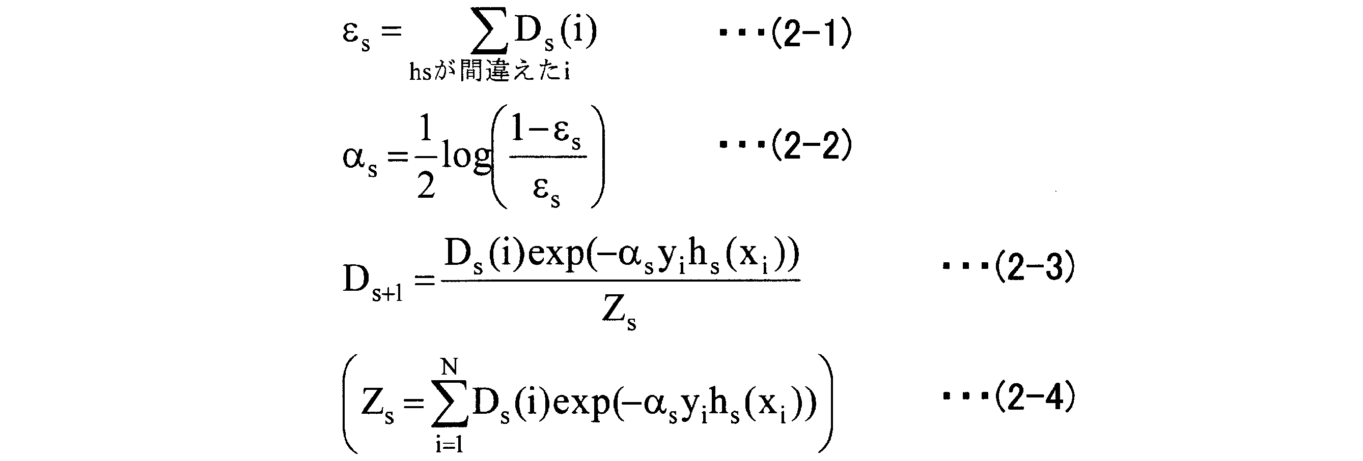
となる。
以下では、図22を用いながら、上記した式(2-1)~式(2-4)についてそれぞれ説明する。同図の(1)に示したように、1回目の学習では、サンプル重みD1(i)を1/Nとしたうえで、判別器hsごとの学習サンプル分布を算出する。このようにすることで、同図に示したように、クラスAの分布とクラスBの分布とが得られる。
そして、同図の(2)に示したように、式(2-1)を用いて判別器hsごとの誤り率(たとえば、クラスAのサンプルをクラスBと誤判別した確率)εsを算出し、最も誤り率εsが低い、すなわち、最も良好な判別を行った判別器hsを最良判別器として選択する。
つづいて、同図の(3-1)に示したように、式(2-2)を用いて判別器hs(同図の(2)で選択された最良判別器)の重み係数αsを決定する。そして、式(2-3)を用いて次回の学習における各学習サンプル重みDs+1を更新する。なお、式(2-3)の分母であるZsは、式(2-4)であらわされる。
このようにして、次回の学習サンプル重みDs+1が更新されると、同図の(4)に示したように、判別器hsごとの学習サンプル分布は、同図の(1)に示した分布とは異なるものとなる。そして、学習回数sをカウントアップし、同図の(4)で算出された分布で同図の(1)に示した分布を更新したうえで、同図の(2)以降の処理を繰り返す。
ここで、式(2-3)は、同図の(2)で選択された最良判別器が、次回の学習では、誤り率が0.5である判別器となるように次回の学習サンプル重みDs+1を決定することを示している。すなわち、最良判別器が最も苦手とする学習サンプル重みを用いて次の最良判別器を選択する処理を行うことになる。
このように、アダブースト手法は、学習を繰り返すことで、判別器の選択と各判別器の重み係数の最適化とを行い、最終的には、正答率が高い最終判別器を導出することができる。しかし、式(1-2)に示したように、アダブースト手法によって選択される判別器hs(x)は、2値化判別器であり、判別器内部で保持する値を最終的には2値に変換したうえで出力する。すなわち、2値変換に伴う判断分岐が必要となり、演算量がかさむという問題がある。
なお、リアルブースト(RealBoost)手法では、多値判別器を用いるので、アダブースト手法で発生する判断分岐による演算量増大の問題を回避することができるが、多値判別器が保持する多値それぞれに対応した重み係数を保持する必要があるため、メモリ使用量が増大するという問題がある。
そこで、アダブースト手法を改良することで、判断分岐による演算量増大という問題を回避するとともに、リアルブースト手法のように大きなメモリを必要とすることなく識別精度を向上させる「LDAArray法」を考案した。以下では、かかるLDAArray法の概要について図13を用いて説明する。
図13は、LDAArray法の概要を示す図である。なお、同図の(A)には、図10を用いて説明したアダブースト手法の概要について、同図の(B)には、LDAArray法の概要についてそれぞれ示している。また、同図の(A)に示したhiは2値化判別器を、同図の(B)に示したfiは、hiが所定の閾値で2値化する前の関数である未2値化判別器を、それぞれあらわしている。
図13の(A)に示したように、アダブースト手法では、1回目の学習で、誤り率が最小の判別器をh1として決定する(同図の(A-1)参照)。そして、h1の重み係数を決定し(同図の(A-2)参照)、次回の学習では、h1が、誤り率が0.5である判別器となるように、各サンプルに対するサンプル重みを更新する(同図の(A-3)参照)。
そして、判別器の選択、選択した判別器に対する重み係数の決定およびサンプル重みの更新を繰り返すことで、最終判別器を導出する。
一方、図13の(B)に示したように、LDAArray法では、所定個数の未2値化判別器fiをLDA(Linear Discriminant Analysis)法を用いて集約することで集約判別器を導出し、導出した1個または複数個の集約判別器に基づいて1個の最終判別器を導出する点に主たる特徴がある。
具体的には、所定の手順に従って未2値化判別器を集約し(同図の(B-1)参照)、LDAを用いて集約判別器を導出する(同図の(B-2)参照)。また、導出した集約判別器の重み係数を決定するとともに(同図の(B-3)参照)、各サンプルに対するサンプル重みを更新する(同図の(B-4)参照)。
そして、集約判別器の選択、選択した集約判別器に対する重み係数の決定およびサンプル重みの更新を繰り返すことで、1個の最終判別器を導出する。このように、LDAArray法では、所定数の未2値化判別器を線形結合するので、判別処理に伴う演算量を削減することができる。
すなわち、排除対象(上記したクラスB)をある程度分離することができるようになるまで未2値化判別器を集約するので、無駄な判断分岐(図13の(A)に示したhiが必ず行う2値変換に伴う判断分岐)を削減することができる。また、図13の(A)に示したアダブースト手法では考慮されていなかった特徴量間の関係を、あらたな特徴として捉えることができるので、判別精度を向上させることができる。
図14は、LDAArray部100の構成を示すブロック図である。同図に示すように、LDAArray部100は、制御部111と、記憶部112とを備えている。また、制御部111は、アダブースト処理部111aと、集約判別器導出部111bと、集約重み係数決定部111cと、サンプル重み更新部111dと、最終判別器決定部111eとをさらに備えている。そして、記憶部112は、顔画像サンプル112aと、非顔画像サンプル112bと、集約判別器候補112cと、集約判別器112dと、集約重み係数112eとを記憶する。
なお、図14では、LDAArray部100が、制御部111および記憶部112を備える場合について示したが、制御部111内の各処理部を、図2に示した制御部11内に配置するとともに、記憶部112が記憶する各情報を、図2に示した記憶部12内に記憶させることとしてもよい。また、図14に示した顔画像サンプル112aと、図2に示した顔画像サンプル12aとを同一とし、図14に示した非顔画像サンプル112bと、図2に示した非顔画像サンプル12bとを同一とすることとしてもよい。
制御部111は、上記したLDAArray法を用いた学習によって最終判別器を導出する処理を行う処理部である。
アダブースト処理部111aは、図22を用いて既に説明したアダブースト手法を実行する処理を行う処理部である。また、アダブースト処理部111aは、記憶部112から読み出した顔画像サンプル112aおよび非顔画像サンプル112bをサンプルとする学習を繰り返し、選択した2値化判別器と決定した重み係数との組を集約判別器導出部111bに渡す処理を併せて行う。
そして、アダブースト処理部111aは、サンプル重み更新部111dから更新後のサンプル重みを受け取った場合には、受け取ったサンプル重みでサンプル重みDs(図22参照)を更新する。つづいて、アダブースト処理部111aは、2値化判別器の選択を最初からやり直す。すなわち、図22に示した学習回数sを1としたうえで、2値化判別器の選択処理等を繰り返す。
ここで、アダブースト処理部111aの学習に用いられる顔画像サンプル112aおよび非顔画像サンプル112bについて図15を用いて説明しておく。図15は、サンプル画像から特徴量を取得する処理を示す図である。
なお、同図の(A)には、顔画像から特徴量を取得する処理の流れを、同図の(B)には、背景画像のような非顔画像から特徴量を取得する処理の流れを、それぞれ示している。また、同図に示した各顔画像および各非顔画像は、事前の拡大/縮小処理によってサイズ合わせがなされているものとする。
同図の(A)に示したように、顔画像を所定サイズのブロックに分割し(同図の(A-1)参照)、各ブロックについて、エッジ方向とその強度(太さ)、全体強度といった特徴量を抽出する(同図の(A-2)参照)。
たとえば、顔画像の左目に相当するブロック161については、上向きエッジ強度162a、右上向きエッジ強度162b、右向きエッジ強度162c、右下向きエッジ強度162d、ブロック161の全体強度162eといった特徴量が抽出される。なお、162a~162eに示した矢印の太さは強度をあらわしている。また、同図に示した162a~162eは、特徴量の一例であり、特徴量の種類は問わない。
このように、各ブロックについて特徴量を抽出する処理を顔画像全体について繰り返すことで、1枚の顔画像についての特徴量が揃うことになる。そして、同様の処理を他の複数枚の顔画像に対しても行うことで、顔画像サンプル112aが得られる。
また、同図の(B)に示したように、非顔画像についても顔画像と同様のブロック分割を行い(同図の(B-1)参照)、各ブロックについて、顔画像と同様の手順で特徴量を抽出する(同図の(B-2)参照)。たとえば、顔画像のブロック161に対応する位置のブロック163についても、上向きエッジ強度164a、右上向きエッジ強度164b、右向きエッジ強度164c、右下向きエッジ強度164d、ブロック163の全体強度164eといった特徴量が抽出される。
このように、各ブロックについて特徴量を抽出する処理を非顔画像全体について繰り返すことで、1枚の非顔画像についての特徴量が揃うことになる。そして、同様の処理を他の複数枚の非顔画像に対しても行うことで、非顔画像サンプル112bが得られる。
集約判別器導出部111bは、上記したLDAArray法における集約判別器112dを導出する処理を行う処理部である。具体的には、この集約判別器導出部111bは、アダブースト処理部111aによって所定個数の2値化判別器が選択されると、選択された2値化判別器と決定された重み係数との組を受け取り、これらの2値化判別器をLDAによって結合することで、集約判別器を導出する処理を行う処理部である。
また、集約判別器導出部111bは、集約判別器の候補となる集約判別器候補112cを2値化判別器の個数に応じてそれぞれ導出し、導出した集約判別器候補112cの中から1つの集約判別器112dを決定する処理を併せて行う。
ここで、LDAArray法について各数式を用いて説明しておく。集約判別器の導出回数をあらわす集約カウンタをt(1≦t≦T)、特徴量をx、特徴量xに対応する集約判別器をKt(x)、所定のオフセット値をthとすると、最終判別器F(x)は、

式(3-1)のようにあらわされる。ここで、関数sign()は、かっこ内の値が0以上であれば+1、0未満であれば-1とする2値化関数である。なお、オフセット値thは、図17を用いて後述するoffsettの算出手順と同様の手順で算出することができる。
また、未2値化判別器をfts(x)、LDAによって算出されるfts(x)の重みをβts、所定のオフセット値をoffsettとすると、集約判別器Kt(x)は、式(3-2)のようにあらわされる。
なお、オフセット値offsettの算出手順については、図17を用いて後述する。また、式(3-2)のオフセット値offsettは必須ではなく、オフセット値offsettを省略したうえで、式(3-1)のオフセット値thで最終的な調整を行うこととしてもよい。
ここで、未2値化判別器fs(i)と、2値化判別器hs(i)との関係は、

式(4)であらわされる。すなわち、未2値化判別器fs(i)を関数sign()で2値化したものが2値化判別器hs(i)となる。
LDAarray法では、集約カウンタtごとに、複数の集約判別器候補の中から集約判別器Kt(x)を1つずつ選択するとともに、選択した集約判別器Kt(x)に対応する重み係数αtを逐次決定していく処理を繰り返すことで、最終判別器F(x)を導出する。以下では、LDAarray法についてさらに詳細に説明する。
xiを各特徴量とし、yiを{-1,+1}(上記したクラスAは+1、上記したクラスBは-1)とすると、学習サンプルは、{(x1,y1),(x2,y2),…,(xN,yN)}とあらわされる。ここで、Nは、判別対象とする特徴量の総数である。
また、Lt(i)を、i番目の学習サンプルについて、t回目の判別器集約を行った場合のサンプル重みとすると、Lt(i)の初期値は、式「L1(i)=1/N」であらわされる。そして、特徴量xiに対応する集約判別器をKt(xi)とすると、LDAarray法に用いられる各数式は、
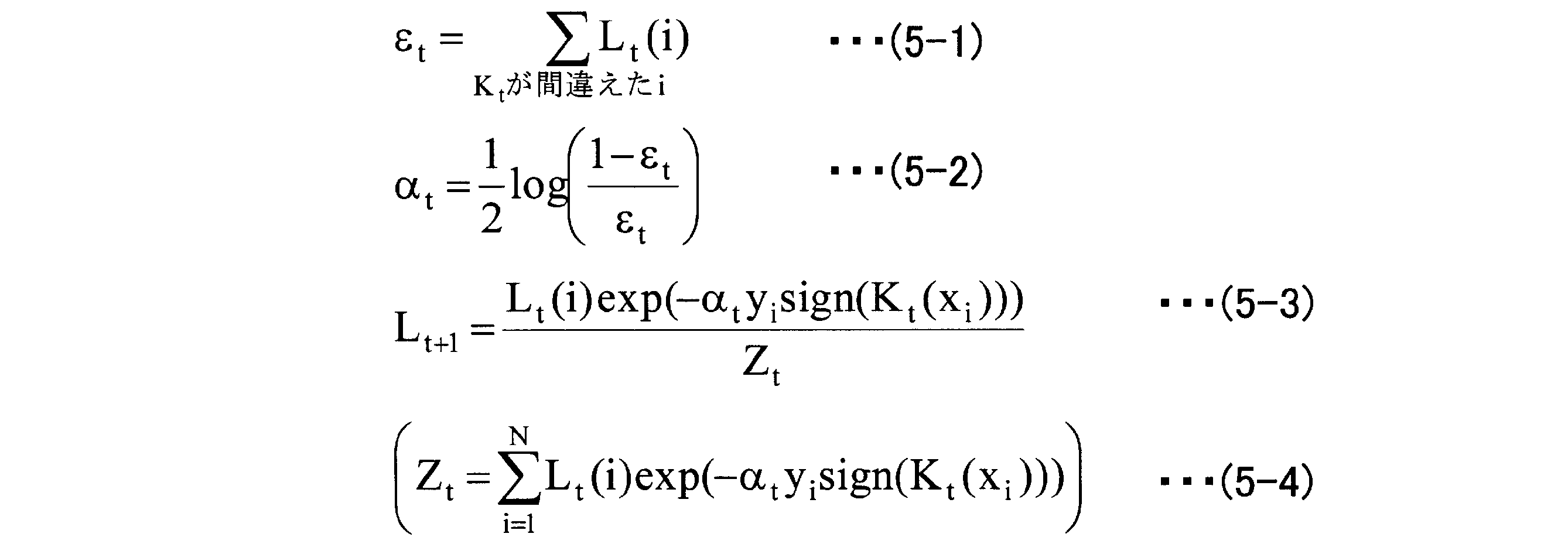
となる。
LDAarray法では、式(5-1)を用いて集約判別器Ktごとの誤り率(たとえば、クラスAのサンプルをクラスBと誤判別した確率)εtを算出する。そして、式(5-1)で算出された誤り率εtおよび式(5-2)を用いて集約判別器Ktの重み係数αtを決定する。さらに、式(5-3)を用いて次回の集約における各学習サンプル重みLt+1を更新する。なお、式(5-3)の分母であるZtは、Lt+1を「ΣLt+1(i)=1」とするための規格化因子であり、式(5-4)であらわされる。
ここで、式(5-3)は、集約判別器Ktが、次回の集約では、誤り率が0.5である判別器となるように次回の学習サンプル重みLt+1を決定することを示している。
このようにして、次回の集約における学習サンプル重みLt+1が更新されると、LDAarray法では、学習サンプル重みLtを、アダブースト処理における学習サンプル重みDsへコピーする。そして、アダブースト処理では、LDAarray法によって更新された学習サンプル重みDsを初期値として判別器選択処理を繰り返すことになる。
図14の説明に戻り、集約判別器導出部111bについての説明をつづける。集約判別器導出部111bは、最小LDA次元数(min_lda_dim)および最大LDA次元数(max_lda_dim)という2つの次元数を有している。ここで、「次元数」とは、たとえば、特徴量の数をあらわすものとする。また、上記した2つの次元数(最小LDA次元数および最大LDA次元数)としては、処理時間と精度との兼ね合いから導出した値(経験値)を用いることができる。
そして、アダブースト処理部111aによって選択された判別器の個数(s)が最小LDA次元数(min_lda_dim)以上となると、LDAによって集約判別器候補112cを導出する。そして、集約判別器候補112cの導出処理を、判別器の個数(s)が最大LDA次元数(max_lda_dim)と等しくなるまで繰り返す。
たとえば、最小LDA次元数(min_lda_dim)が2であり、最大LDA次元数(max_lda_dim)が5である場合には、2個の判別器を集約した集約判別器候補112c、3個の判別器を集約した集約判別器候補112c、4個の判別器を集約した集約判別器候補112c、5個の判別器を集約した集約判別器候補112cをそれぞれ導出し、導出した集約判別器候補112cの中から1つの集約判別器112dを選択する。
ここで、集約判別器導出部111bが行う集約判別器候補算出処理の概要について図16を用いて説明しておく。図16は、集約判別器候補を算出する処理を示す図である。なお、同図では、最小LDA次元数(min_lda_dim)が4であり、最大LDA次元数(max_lda_dim)が20である場合について示している。
集約判別器導出部111bは、アダブースト処理部111aによって選択された判別器の個数(s)が4、すなわち、最小LDA次元数(min_lda_dim)と等しくなると、クラスA(顔画像サンプル112a)およびクラスB(非顔画像サンプル112b)を用いてLDAによる判別分析を行う。このようにして、sが4である場合の集約判別器の候補kt4(x)を算出する。そして、同様の処理をsが20、すなわち、最大LDA次元数(max_lda_dim)と等しくなるまで繰り返す。
ここで、図16に示した各オフセット値(offsettn)の算出手順について図17を用いて説明しておく。図17は、集約判別器候補112cのオフセットを算出する処理を示す図である。なお、同図に示す181a、182aおよび183aは、クラスA(顔画像サンプル112a)の確率密度分布をあらわすグラフを、同図に示す181b、182bおよび183bは、クラスB(非顔画像サンプル112b)の確率密度分布をあらわすグラフを、それぞれ示している。また、同図に示した横軸は各集約判別器候補(ks)の値を、同図に示した縦軸は確率密度を、それぞれあらわしている。
図17に示したように、offsett4は、クラスAのグラフ181aとクラスBのグラフ181bとが、交差する点に対応する横軸値として算出される。すなわち、offsett4は、顔画像を非顔画像と誤認識した確率と非顔画像を顔画像と誤認識した確率とが等しいように調整される。また、誤り率εt4は、同図に示した斜線部の面積として算出される。
なお、図17に示したように、LDA次元数(s)の変化にともなって、offsettnの値も変化する。このため、集約判別器導出部111bは、LDA次元数(s)ごとにoffsettnをそれぞれ算出する。
集約判別器導出部111bは、図16および図17に示した処理を行うことで、各集約判別器の候補ktn(x)を、それぞれ算出する。つづいて、集約判別器導出部111bは、算出した集約判別器候補112cの中から1つの集約判別器112dを選択する処理を行う。ここで、かかる選択処理の一例について図18を用いて説明しておく。
図18は、集約判別器選択の一例を示す図である。なお、同図には、最小LDA次元数(min_lda_dim)から最大LDA次元数(max_lda_dim)までの間で1回だけLDA関数を実行させると仮定した場合におけるスキャン総面積(クラスBなどのサンプル画像に対するスキャン総面積)の変化をあらわすグラフ191を示している。また、同図では、グラフ191が、LDA次元数(s)が6のときに最小値192をとる場合について例示している。
たとえば、LDA関数を実行させるLDA次元数(s)をnとすると、スキャン総面積は、n×画像面積+(max_lda_dim-n)×(n回の全面スキャンで排除できなかったエリアの面積)となる。このようにして算出されたスキャン総面積とnとの関係は、たとえば、グラフ191のようになる。
ここで、同図では、LDA次元数(s)が6の場合に最小値192をとる場合について示したが、集約カウンタtが変化すると、スキャン総面積が最小となる次元数も変化する。このため、集約判別器導出部111bは、集約カウンタtに対応する集約判別器候補112cを用いて図18に示した判定処理を行い、スキャン総面積が最小となるLDA次元数(s)の候補ktnを、集約判別器Ktとして選択する。
なお、図18では、スキャン総面積が最小となるLDA次元数(s)を有する候補ktnを、集約判別器Ktとして選択する場合について示したが、LDA次元数(s)を固定することとしてもよい。このようにすることで、LDA処理の処理負荷が集約カウンタtによって変化しないので、並列処理が可能となる。したがって、処理時間の短縮を図ることができる。
図14の説明に戻り、集約重み係数決定部111cについて説明する。集約重み係数決定部111cは、集約判別器導出部111bが集約判別器Ktを導出した場合に、集約判別器Ktに対する重み係数(集約重み係数αt)を決定し、集約重み係数112eとして記憶部112へ記憶させる処理を行う処理部である。なお、集約重み係数αtは、上記した式(5-2)を用いて算出される。
サンプル重み更新部111dは、集約判別器導出部111bによって導出された集約判別器Ktおよび集約重み係数決定部111cによって決定された集約重み係数αtに基づいて次回の集約における各学習サンプル重みLt+1を更新する処理(式(5-3)参照)を行う処理部である。また、サンプル重み更新部111dは、学習サンプル重みLtを、アダブースト処理部111aが用いる学習サンプル重みDsへコピーする処理を行う処理部でもある。
このようにして、集約カウンタtをカウントアップしながら、集約カウンタtに対応する集約判別器112dおよび集約重み係数112eが記憶部112へ記憶されていく。そして、最終判別器決定部111eは、集約判別器112d(Kt)および集約重み係数112e(αt)を用いた最終判別器Fの正答率が所定値以上となったことを条件として集約カウンタtを用いたループを終了する。なお、最終判別器決定部111eは、集約対象とする2値化判別器(hs)がない場合にもかかるループを終了する。
ここで、制御部111によって行われる集約判別器導出処理についてまとめておく。図19は、集約判別器Ktを導出する処理を示す図である。同図に示したように、制御部111は、LDA候補(集約判別器候補)抽出を行い(同図の(A)参照)、学習1回目の集約判別器K1を決定する(同図の(B)参照)。
そして、K1を決定したならば、つづいて、K2の決定処理を開始し(同図の(C)参照)、K2を決定する(同図の(D)参照)。さらに、K3の決定処理を開始し(同図の(E)参照)、K3、K4を順次決定していく。なお、同図では、K1のLDA次元数が4で、K2のLDA次元数が5である場合について示しているが、このように、後続のKになるほどLDA次元数が増加するとは限らない。
図14の説明に戻り、記憶部112について説明する。記憶部112は、不揮発性メモリやハードディスクドライブといった記憶デバイスで構成される記憶部であり、顔画像サンプル112aと、非顔画像サンプル112bと、集約判別器候補112cと、集約判別器112dと、集約重み係数112eとを記憶する。なお、記憶部112に記憶される各情報については、制御部111の説明において既に説明したので、ここでの説明は省略する。
次に、LDAArray部100が実行する処理手順について図20を用いて説明する。図20は、LDAArray部100が実行する処理手順を示すフローチャートである。同図に示すように、最小LDA次元(min_lda_dim)および最大LDA次元(max_lda_dim)を設定し(ステップS301)、集約カウンタ(t)を1とするとともに(ステップS302)、アダブーストカウンタ(s)を1とする(ステップS303)。なお、集約カウンタ(t)およびアダブーストカウンタ(s)を用いて図19における判別器fをあらわすと、ft-sとなる。
そして、アダブースト処理部111aは、最良判別器(hs)を選択し(ステップS304)、ステップS304で選択された最良判別器(hs)の重み係数(αs)を算出するとともに(ステップS305)、各サンプルに対するサンプル重み(Ds)を更新する(ステップS306)。
つづいて、集約判別器導出部111bは、アダブーストカウンタ(s)が最小LDA次元数(min_lda_dim)以上であるか否かを判定し(ステップS307)、アダブーストカウンタ(s)が最小LDA次元数(min_lda_dim)未満である場合には(ステップS307,No)、アダブーストカウンタ(s)をカウントアップし(ステップS310)、ステップS304以降の処理を繰り返す。
一方、アダブーストカウンタ(s)が最小LDA次元数(min_lda_dim)以上である場合には(ステップS307,Yes)、未2値化判別器(f1~fs)についてLDAを行い、集約判別器候補(ks)を算出する(ステップS308)。
つづいて、アダブーストカウンタ(s)が最大LDA次元数(max_lda_dim)と等しいか否かを判定し(ステップS309)、アダブーストカウンタ(s)が最大LDA次元数(max_lda_dim)と等しくない場合には(ステップS309,No)、アダブーストカウンタ(s)をカウントアップし(ステップS310)、ステップS304以降の処理を繰り返す。
一方、アダブーストカウンタ(s)が最大LDA次元数(max_lda_dim)と等しい場合には(ステップS309,Yes)、集約判別器(Kt)を決定する処理を行う(ステップS311)。なお、ステップS311の詳細な処理手順については、図21を用いて後述することとする。
つづいて、集約重み係数決定部111cは、集約判別器(Kt)の重み係数(αt)を決定し(ステップS312)、サンプル重み更新部111dは、サンプル重み(Lt)を更新する(ステップS313)。そして、最終判別器決定部111eは、最終判別器(F)による判別結果に基づいてクラスAとクラスBとの分離が十分であるか、または、未集約判別器がないか、のいずれかの条件を満たすか否かを判定する(ステップS314)。
そして、ステップS314の判定条件を満たした場合には(ステップS314,Yes)、最終判別器(F)を決定して処理を終了する。一方、ステップS314の判定条件を満たさなかった場合には(ステップS314,No)、集約判別器導出部111bが用いるサンプル重み(Lt)をアダブースト処理部111aが用いるサンプル重み(Ds)へコピーする(ステップS315)。そして、集約カウンタ(t)をカウントアップし(ステップS316)、ステップS303以降の処理を繰り返す。
次に、図20のステップS311に示した集約判別器決定処理の詳細な処理手順について図21を用いて説明する。図21は、集約判別器決定処理の処理手順を示すフローチャートである。同図に示すように、集約判別器導出部111bは、LDA次元数(s)の初期値を最小LDA次元数(min_lda_dim)とし(ステップS401)、全面スキャン総面積(s×全面積)を算出する(ステップS402)。
つづいて、s回の全面スキャンで排除できなかったエリアの面積を残存面積としたうえで(ステップS403)、部分スキャン総面積((max_lda_dim-s)×残存面積)を算出する(ステップS404)。そして、総スキャン面積(全面スキャン総面積+部分スキャン総面積)を算出する(ステップS405)。
つづいて、sが最大LDA次元数(max_lda_dim)と等しいか否かを判定し(ステップS406)、sが最大LDA次元数(max_lda_dim)と等しくない場合には(ステップS406,No)、sをカウントアップしたうえで(ステップS407)、ステップS402以降の処理を繰り返す。一方、sが最大LDA次元数(max_lda_dim)と等しい場合には(ステップS406,Yes)、総スキャン面積が最も小さいLDA次元数(s)に対応する集約判別器候補(ks)を集約判別器(Kt)とし(ステップS408)、処理を終了する。
このようにLDAArray法によれば、アダブースト手法における判断分岐による演算量増大という問題を回避するとともに、リアルブースト手法のように大きなメモリを必要とすることなく識別精度を向上させることができる。
以上のように、本発明に係る被写体識別方法、被写体識別プログラムおよび被写体識別装置は、所定の画像から特定の被写体を識別する処理を高速かつ高精度に行いたい場合に有用であり、特に、判別器を配置した識別用木構造を動的に生成したい場合に適している。
Claims (11)
- 木構造の各ノードにそれぞれ配置された判別器を用い、前記木構造の頂点であるルートノードから末端のリーフノードへ向かって前記判別器を適用していくことで被写体画像と非被写体画像とを識別する被写体識別方法であって、
被写体画像サンプルと非被写体画像サンプルとの分離に用いる複数の特徴量を両サンプルの分離度が高いほうから所定数だけ選択する特徴量選択工程と、
前記特徴量選択工程によって選択された前記特徴量について、前記非被写体画像サンプルと最も分離している前記被写体画像サンプルを最分離サンプルとして選択する最分離サンプル選択工程と、
前記最分離サンプル選択工程によって選択された前記最分離サンプルを含んだ部分集合を前記被写体画像サンプルから抽出するとともに前記部分集合に対応する前記判別器をLDAArray法による学習によって導出し、当該判別器に基づいて前記部分集合を拡張していくことで前記部分集合を決定する部分集合決定工程と、
前記部分集合決定工程によって決定された前記部分集合を前記被写体画像サンプルから除去したうえで、前記特徴量選択工程、前記最分離サンプル選択工程および前記部分集合決定工程を繰り返すことで得られた前記部分集合および当該部分集合に対応する前記判別器の組を前記リーフノードとしてそれぞれ決定するリーフノード決定工程と
を含んだことを特徴とする被写体識別方法。 - 前記部分集合決定工程は、
前記最分離サンプルを含んだ前記部分集合を前記被写体画像サンプルから最初に抽出する場合に、当該最分離サンプルからの距離が短いほうから所定数の前記被写体画像サンプルを当該部分集合に含めて抽出することを特徴とする請求項1に記載の被写体識別方法。 - 前記部分集合決定工程は、
前記部分集合の変動数が所定の閾値未満となった場合に、前記部分集合の拡張を停止することを特徴とする請求項2に記載の被写体識別方法。 - 前記リーフノード決定工程によって前記リーフノードとしてそれぞれ決定された前記部分集合からなる母集合を所定個数の前記部分集合を含んだノード候補の集合としてあらわした分岐案について、前記分岐案による前記非被写体画像サンプルのアクセプト率を示す評価値を前記分岐案ごとにそれぞれ算出する評価値算出工程と、
前記評価値算出工程によって算出された前記評価値が最小となる前記分岐案に含まれる前記ノード候補のそれぞれを前記ルートノード直下のノードとして決定するとともに、前記ノード候補に複数の前記部分集合が含まれる場合には、当該ノード候補に含まれる前記部分集合の個数が1となるまで前記ノードの決定を繰り返すことで、全てのノードを決定する全ノード決定工程と
をさらに含んだことを特徴とする請求項1、2または3に記載の被写体識別方法。 - 前記評価値算出工程は、
前記リーフノード決定工程によって前記リーフノードとしてそれぞれ決定された前記部分集合および当該部分集合に対応する前記判別器について、いずれか1つの前記判別器に対していずれか1つの前記部分集合の入力を仮定したすべての組合せごとに前記非被写体画像サンプルのアクセプト率をそれぞれ算出し、該アクセプト率に基づいて前記分岐案についての前記評価値を算出することを特徴とする請求項4に記載の被写体識別方法。 - 前記評価値算出工程は、
前記分岐案に含まれるすべての前記ノード候補ごとに、当該ノード候補に含まれるすべての前記部分集合について最大の前記アクセプト率を当該ノード候補の代表アクセプト率としたうえで、前記分岐案に含まれる前記ノード候補の前記代表アクセプト率に基づいて前記分岐案についての前記評価値を算出することを特徴とする請求項5に記載の被写体識別方法。 - 前記全ノード決定工程は、
前記ノードとして決定された前記ノード候補に複数の前記部分集合が含まれる場合には、前記非被写体画像サンプルおよび当該ノード候補に含まれるすべての前記部分集合を入力としたLDAArray法による学習によって当該ノード候補に対応する前記判別器を導出することを特徴とする請求項4、5または6に記載の被写体識別方法。 - 前記判別器が前記非被写体画像サンプルを演算する段数が最小となるように当該判別器におけるLDAArray段数を決定するLDAArray段数決定工程をさらに含んだことを特徴とする請求項1~7のいずれか一つに記載の被写体識別方法。
- 前記LDAArray段数決定工程は、
前記判別器に対応する前記ノードが配下ノードを有する場合には、当該ノードにおける前記LDAArray段数およびすべての前記配下ノードにおける前記LDAArray段数との総和である総LDAArray段数が最小となるように前記LDAArray段数を決定することを特徴とする請求項8に記載の被写体識別方法。 - 木構造の各ノードにそれぞれ配置された判別器を用い、前記木構造の頂点であるルートノードから末端のリーフノードへ向かって前記判別器を適用していくことで被写体画像と非被写体画像とを識別する被写体識別プログラムであって、
被写体画像サンプルと非被写体画像サンプルとの分離に用いる複数の特徴量を両サンプルの分離度が高いほうから所定数だけ選択する特徴量選択手順と、
前記特徴量選択手順によって選択された前記特徴量について、前記非被写体画像サンプルと最も分離している前記被写体画像サンプルを最分離サンプルとして選択する最分離サンプル選択手順と、
前記最分離サンプル選択手順によって選択された前記最分離サンプルを含んだ部分集合を前記被写体画像サンプルから抽出するとともに前記部分集合に対応する前記判別器をLDAArray法による学習によって導出し、当該判別器に基づいて前記部分集合を拡張していくことで前記部分集合を決定する部分集合決定手順と、
前記部分集合決定手順によって決定された前記部分集合を前記被写体画像サンプルから除去したうえで、前記特徴量選択手順、前記最分離サンプル選択手順および前記部分集合決定手順を繰り返すことで得られた前記部分集合および当該部分集合に対応する前記判別器の組を前記リーフノードとしてそれぞれ決定するリーフノード決定手順と
をコンピュータに実行させることを特徴とする被写体識別プログラム。 - 木構造の各ノードにそれぞれ配置された判別器を用い、前記木構造の頂点であるルートノードから末端のリーフノードへ向かって前記判別器を適用していくことで被写体画像と非被写体画像とを識別する被写体識別装置であって、
被写体画像サンプルと非被写体画像サンプルとの分離に用いる複数の特徴量を両サンプルの分離度が高いほうから所定数だけ選択する特徴量選択手段と、
前記特徴量選択手段によって選択された前記特徴量について、前記非被写体画像サンプルと最も分離している前記被写体画像サンプルを最分離サンプルとして選択する最分離サンプル選択手段と、
前記最分離サンプル選択手段によって選択された前記最分離サンプルを含んだ部分集合を前記被写体画像サンプルから抽出するとともに前記部分集合に対応する前記判別器をLDAArray法による学習によって導出し、当該判別器に基づいて前記部分集合を拡張していくことで前記部分集合を決定する部分集合決定手段と、
前記部分集合決定手段によって決定された前記部分集合を前記被写体画像サンプルから除去したうえで、前記特徴量選択手段、前記最分離サンプル選択手段および前記部分集合決定手段を繰り返すことで得られた前記部分集合および当該部分集合に対応する前記判別器の組を前記リーフノードとしてそれぞれ決定するリーフノード決定手段と
を備えたことを特徴とする被写体識別装置。
Priority Applications (1)
| Application Number | Priority Date | Filing Date | Title |
|---|---|---|---|
| PCT/JP2009/056230 WO2010109645A1 (ja) | 2009-03-27 | 2009-03-27 | 被写体識別方法、被写体識別プログラムおよび被写体識別装置 |
Applications Claiming Priority (1)
| Application Number | Priority Date | Filing Date | Title |
|---|---|---|---|
| PCT/JP2009/056230 WO2010109645A1 (ja) | 2009-03-27 | 2009-03-27 | 被写体識別方法、被写体識別プログラムおよび被写体識別装置 |
Publications (1)
| Publication Number | Publication Date |
|---|---|
| WO2010109645A1 true WO2010109645A1 (ja) | 2010-09-30 |
Family
ID=42780354
Family Applications (1)
| Application Number | Title | Priority Date | Filing Date |
|---|---|---|---|
| PCT/JP2009/056230 Ceased WO2010109645A1 (ja) | 2009-03-27 | 2009-03-27 | 被写体識別方法、被写体識別プログラムおよび被写体識別装置 |
Country Status (1)
| Country | Link |
|---|---|
| WO (1) | WO2010109645A1 (ja) |
Cited By (6)
| Publication number | Priority date | Publication date | Assignee | Title |
|---|---|---|---|---|
| WO2012060463A1 (ja) * | 2010-11-05 | 2012-05-10 | グローリー株式会社 | 被写体検出方法および被写体検出装置 |
| JP2013045433A (ja) * | 2011-08-26 | 2013-03-04 | Canon Inc | 学習装置、学習装置の制御方法、検出装置、検出装置の制御方法、およびプログラム |
| WO2015146389A1 (ja) * | 2014-03-26 | 2015-10-01 | 株式会社メガチップス | 物体検出装置 |
| US10846295B1 (en) | 2019-08-08 | 2020-11-24 | Applied Underwriters, Inc. | Semantic analysis system for ranking search results |
| CN112036502A (zh) * | 2020-09-07 | 2020-12-04 | 杭州海康威视数字技术股份有限公司 | 图像数据比对方法、装置及系统 |
| US11809434B1 (en) | 2014-03-11 | 2023-11-07 | Applied Underwriters, Inc. | Semantic analysis system for ranking search results |
Citations (1)
| Publication number | Priority date | Publication date | Assignee | Title |
|---|---|---|---|---|
| JP2002014816A (ja) * | 2000-05-02 | 2002-01-18 | Internatl Business Mach Corp <Ibm> | 判別式で決定木を生成し、それをデータ分類に使用するための方法および装置 |
-
2009
- 2009-03-27 WO PCT/JP2009/056230 patent/WO2010109645A1/ja not_active Ceased
Patent Citations (1)
| Publication number | Priority date | Publication date | Assignee | Title |
|---|---|---|---|---|
| JP2002014816A (ja) * | 2000-05-02 | 2002-01-18 | Internatl Business Mach Corp <Ibm> | 判別式で決定木を生成し、それをデータ分類に使用するための方法および装置 |
Non-Patent Citations (2)
| Title |
|---|
| KANNO ET AL.: "Tadan Ryushi Filter o Mochiita Buttai Ninshiki no Heiretsu Jisso", IEICE TECHNICAL REPORT SIS, vol. 108, no. 85, 5 June 2008 (2008-06-05), pages 11 - 16 * |
| MURATA: "Boosting no Kikagakuteki Kosatsu", IEICE TECHNICAL REPORT NC, vol. 102, no. 381, 10 October 2002 (2002-10-10), pages 37 - 42 * |
Cited By (9)
| Publication number | Priority date | Publication date | Assignee | Title |
|---|---|---|---|---|
| WO2012060463A1 (ja) * | 2010-11-05 | 2012-05-10 | グローリー株式会社 | 被写体検出方法および被写体検出装置 |
| JP2012099070A (ja) * | 2010-11-05 | 2012-05-24 | Glory Ltd | 被写体検出方法および被写体検出装置 |
| JP2013045433A (ja) * | 2011-08-26 | 2013-03-04 | Canon Inc | 学習装置、学習装置の制御方法、検出装置、検出装置の制御方法、およびプログラム |
| US11809434B1 (en) | 2014-03-11 | 2023-11-07 | Applied Underwriters, Inc. | Semantic analysis system for ranking search results |
| WO2015146389A1 (ja) * | 2014-03-26 | 2015-10-01 | 株式会社メガチップス | 物体検出装置 |
| JP2015187782A (ja) * | 2014-03-26 | 2015-10-29 | 株式会社メガチップス | 物体検出装置 |
| US10846295B1 (en) | 2019-08-08 | 2020-11-24 | Applied Underwriters, Inc. | Semantic analysis system for ranking search results |
| CN112036502A (zh) * | 2020-09-07 | 2020-12-04 | 杭州海康威视数字技术股份有限公司 | 图像数据比对方法、装置及系统 |
| CN112036502B (zh) * | 2020-09-07 | 2023-08-08 | 杭州海康威视数字技术股份有限公司 | 图像数据比对方法、装置及系统 |
Similar Documents
| Publication | Publication Date | Title |
|---|---|---|
| Nandakumar et al. | Likelihood ratio-based biometric score fusion | |
| CN107423701B (zh) | 基于生成式对抗网络的人脸非监督特征学习方法及装置 | |
| US20120257802A1 (en) | Apparatus and method for generating representative fingerprint template | |
| JP5706131B2 (ja) | 被写体検出方法および被写体検出装置 | |
| Fang et al. | Deep learning multi-layer fusion for an accurate iris presentation attack detection | |
| US20110235901A1 (en) | Method, apparatus, and program for generating classifiers | |
| Riazi et al. | Synfi: Automatic synthetic fingerprint generation | |
| US10002285B2 (en) | Fast, high-accuracy, large-scale fingerprint verification system | |
| US20200293807A1 (en) | Adaptive image cropping for face recognition | |
| Makrushin et al. | Dempster-shafer theory for fusing face morphing detectors | |
| CN108427923A (zh) | 一种掌纹识别方法及装置 | |
| Eskander et al. | Adaptation of writer-independent systems for offline signature verification | |
| Arif et al. | A fusion methodology based on Dempster-Shafer evidence theory for two biometric applications | |
| Rabinowitz et al. | Ghost: Gaussian hypothesis open-set technique | |
| Jung et al. | Fingerprint classification using the stochastic approach of ridge direction information | |
| JP5840083B2 (ja) | 画像処理装置 | |
| Almaz et al. | A non-rigid feature extraction method for shape recognition | |
| Prakash et al. | Geometric centroids and their relative distances for off-line signature verification | |
| Ding et al. | Side-view face authentication based on wavelet and random forest with subsets | |
| Abbas et al. | Combination of off-line and on-line signature verification systems based on SVM and DST | |
| Hapsari et al. | Identification of Indonesian Rupiah Paper Currency Denominations Using First Order Statistical Feature Extraction and k-Nearest Neighbor | |
| Mohammed et al. | Off-line handwritten signature recognition based on genetic algorithm and Euclidean distance | |
| JP5290401B2 (ja) | 被写体識別方法、被写体識別プログラムおよび被写体識別装置 | |
| Azmi et al. | Freeman chain code (FCC) representation in signature fraud detection based on nearest neighbour and artificial neural network (ANN) classifiers | |
| JP2012230639A (ja) | 認識装置、認識方法及びプログラム |
Legal Events
| Date | Code | Title | Description |
|---|---|---|---|
| 121 | Ep: the epo has been informed by wipo that ep was designated in this application |
Ref document number: 09842259 Country of ref document: EP Kind code of ref document: A1 |
|
| NENP | Non-entry into the national phase |
Ref country code: DE |
|
| 122 | Ep: pct application non-entry in european phase |
Ref document number: 09842259 Country of ref document: EP Kind code of ref document: A1 |
|
| NENP | Non-entry into the national phase |
Ref country code: JP |