WO2010104057A1 - ヒートポンプ装置 - Google Patents
ヒートポンプ装置 Download PDFInfo
- Publication number
- WO2010104057A1 WO2010104057A1 PCT/JP2010/053842 JP2010053842W WO2010104057A1 WO 2010104057 A1 WO2010104057 A1 WO 2010104057A1 JP 2010053842 W JP2010053842 W JP 2010053842W WO 2010104057 A1 WO2010104057 A1 WO 2010104057A1
- Authority
- WO
- WIPO (PCT)
- Prior art keywords
- refrigerant
- evaporator
- heat pump
- condenser
- turbo compressor
- Prior art date
Links
Images


Classifications
-
- F—MECHANICAL ENGINEERING; LIGHTING; HEATING; WEAPONS; BLASTING
- F25—REFRIGERATION OR COOLING; COMBINED HEATING AND REFRIGERATION SYSTEMS; HEAT PUMP SYSTEMS; MANUFACTURE OR STORAGE OF ICE; LIQUEFACTION SOLIDIFICATION OF GASES
- F25B—REFRIGERATION MACHINES, PLANTS OR SYSTEMS; COMBINED HEATING AND REFRIGERATION SYSTEMS; HEAT PUMP SYSTEMS
- F25B30/00—Heat pumps
- F25B30/02—Heat pumps of the compression type
-
- F—MECHANICAL ENGINEERING; LIGHTING; HEATING; WEAPONS; BLASTING
- F25—REFRIGERATION OR COOLING; COMBINED HEATING AND REFRIGERATION SYSTEMS; HEAT PUMP SYSTEMS; MANUFACTURE OR STORAGE OF ICE; LIQUEFACTION SOLIDIFICATION OF GASES
- F25B—REFRIGERATION MACHINES, PLANTS OR SYSTEMS; COMBINED HEATING AND REFRIGERATION SYSTEMS; HEAT PUMP SYSTEMS
- F25B43/00—Arrangements for separating or purifying gases or liquids; Arrangements for vaporising the residuum of liquid refrigerant, e.g. by heat
- F25B43/006—Accumulators
-
- F—MECHANICAL ENGINEERING; LIGHTING; HEATING; WEAPONS; BLASTING
- F25—REFRIGERATION OR COOLING; COMBINED HEATING AND REFRIGERATION SYSTEMS; HEAT PUMP SYSTEMS; MANUFACTURE OR STORAGE OF ICE; LIQUEFACTION SOLIDIFICATION OF GASES
- F25B—REFRIGERATION MACHINES, PLANTS OR SYSTEMS; COMBINED HEATING AND REFRIGERATION SYSTEMS; HEAT PUMP SYSTEMS
- F25B43/00—Arrangements for separating or purifying gases or liquids; Arrangements for vaporising the residuum of liquid refrigerant, e.g. by heat
- F25B43/02—Arrangements for separating or purifying gases or liquids; Arrangements for vaporising the residuum of liquid refrigerant, e.g. by heat for separating lubricants from the refrigerant
-
- F—MECHANICAL ENGINEERING; LIGHTING; HEATING; WEAPONS; BLASTING
- F25—REFRIGERATION OR COOLING; COMBINED HEATING AND REFRIGERATION SYSTEMS; HEAT PUMP SYSTEMS; MANUFACTURE OR STORAGE OF ICE; LIQUEFACTION SOLIDIFICATION OF GASES
- F25B—REFRIGERATION MACHINES, PLANTS OR SYSTEMS; COMBINED HEATING AND REFRIGERATION SYSTEMS; HEAT PUMP SYSTEMS
- F25B1/00—Compression machines, plants or systems with non-reversible cycle
- F25B1/04—Compression machines, plants or systems with non-reversible cycle with compressor of rotary type
- F25B1/053—Compression machines, plants or systems with non-reversible cycle with compressor of rotary type of turbine type
-
- F—MECHANICAL ENGINEERING; LIGHTING; HEATING; WEAPONS; BLASTING
- F25—REFRIGERATION OR COOLING; COMBINED HEATING AND REFRIGERATION SYSTEMS; HEAT PUMP SYSTEMS; MANUFACTURE OR STORAGE OF ICE; LIQUEFACTION SOLIDIFICATION OF GASES
- F25D—REFRIGERATORS; COLD ROOMS; ICE-BOXES; COOLING OR FREEZING APPARATUS NOT OTHERWISE PROVIDED FOR
- F25D23/00—General constructional features
- F25D23/006—General constructional features for mounting refrigerating machinery components
Definitions
- the present invention relates to a heat pump device, particularly a heat pump device using a turbo refrigerator.
- a shell-and-tube heat exchanger is used as a heat exchanger in a turbo refrigerator used in a heat pump device. And it was common that the compressor is arrange
- a shell-and-tube heat exchanger is generally a cylindrical container, and it is known that it is an advantageous shape for reducing its thickness as a container for storing high-pressure refrigerant.
- This invention was made in order to solve said subject, Comprising: It aims at providing the heat pump apparatus which can suppress the increase in an installation area or a volume.
- the heat pump device of the present invention is a heat pump device provided with a turbo compressor that compresses a refrigerant, a condenser that liquefies the compressed refrigerant, and an evaporator that evaporates the liquefied refrigerant.
- the evaporator and the evaporator are plate heat exchangers.
- a plate heat exchanger that can be formed in a rectangular parallelepiped shape, when placing other components in the heat pump device, the condenser and the evaporator, and other components It becomes difficult to generate a gap between them. Therefore, an increase in installation area and volume in the heat pump device can be suppressed.
- the control unit that drives and controls the turbo compressor, the oil separation unit that separates lubricating oil from the refrigerant discharged from the turbo compressor, and the refrigerant that flows out of the evaporator flows into the gas refrigerant And a liquid / liquid separator, and a gas / liquid separator that supplies only the gaseous refrigerant to the evaporator is provided, the condenser and the evaporator are arranged side by side, and the oil separator is The condenser and the evaporator are disposed on the same plane, the control unit is disposed above one of the evaporator and the evaporator, and the gas-liquid separation unit is disposed above the other of the condenser and the evaporator. It is desirable that the turbo compressor is disposed above the oil separation unit.
- control unit By disposing the control unit above one of the condenser and the evaporator, it becomes easy to secure a flow path of air for cooling the control unit.
- the gas-liquid separator above the other of the condenser and the evaporator, the refrigerant inside the gas-liquid separator flows into the evaporator when the heat pump device is stopped. It is possible to prevent the refrigerant from accumulating.
- the turbo compressor By placing the turbo compressor above the oil separator, in other words, by placing the oil separator below the turbo compressor, when the heat pump device is stopped, the refrigerant inside the turbo compressor is oil separated. Therefore, the refrigerant can be prevented from collecting in the turbo compressor.
- an increase in installation area and volume can be suppressed by using a plate heat exchanger that can be formed in a rectangular parallelepiped shape.
- FIG. 1 It is a schematic diagram explaining the circuit structure in the heat pump apparatus which concerns on one Embodiment of this invention. It is a front view explaining arrangement
- FIG. 1 is a schematic diagram illustrating a circuit configuration in the heat pump apparatus according to the present embodiment.
- the heat pump device 1 is configured in a substantially rectangular parallelepiped shape, and receives supply of heat source water and supplies hot water.
- the heat pump apparatus 1 includes a condenser 2, an expansion valve 3, an evaporator 4, a turbo compressor 5, an inverter unit (control unit) 6, and an oil mist separation tank (oil separation). Part) 7 and an oil tank 8 are mainly provided.
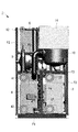
- FIG. 2 is a front view for explaining the arrangement inside the heat pump apparatus of FIG.
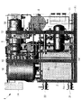
- FIG. 3 is a right side view for explaining the arrangement inside the heat pump apparatus of FIG. 2.
- FIG. 4 is a left side view for explaining the arrangement inside the heat pump apparatus of FIG. 2.
- FIG. 5 is a top view for explaining the arrangement inside the heat pump apparatus of FIG. 2.
- FIG. 6 is a rear view for explaining the arrangement inside the heat pump apparatus of FIG. 2.
- the condenser 2 is a plate heat exchanger formed in a substantially rectangular parallelepiped shape, and cools and condenses the high-temperature and high-pressure refrigerant discharged from the turbo compressor 5. In other words, heat exchange is performed between the refrigerant and the hot water to liquefy the refrigerant and to heat the hot water.
- One end of the condenser 2 is connected to the discharge part of the turbo compressor 5 through the oil mist separation tank 7 so that the refrigerant can flow, and the other end is connected to the expansion valve 3 through the intermediate cooler 9.
- the refrigerant is connected to be able to flow.
- the condenser 2 is on one end side (left end portion side in FIG. 6) in the longitudinal direction (left-right direction in FIG. 6) of the base portion F1 configured in a rectangular shape. In addition, it is arranged at the end on the back side (right side in FIG. 3) and arranged side by side with the evaporator 4.
- the condenser 2 is disposed above the base portion F1 and below the accumulator 10 at a position adjacent to the oil mist separation tank 7 in the above-described longitudinal direction, and to the evaporator 4 and the longitudinal direction. It arrange
- the intercooler 9 is a heat exchanger that further cools the refrigerant that has flowed out of the condenser 2 formed in a substantially cylindrical shape. One end of the intercooler 9 is connected so that the condenser 2 and the refrigerant can flow, and the other end is connected so that the expansion valve 3 and the refrigerant can flow.
- the intercooler 9 heat exchange is performed between the refrigerant that has been adiabatically expanded to a low temperature and low pressure by partially cooling the refrigerant that has flowed out of the condenser 2, and the refrigerant that is supplied to the expansion valve 3.
- the explanation is applied to an example.
- the refrigerant used for cooling the expansion valve 3 flows into the turbo compressor 5.
- a well-known structure can be used as a structure of the intercooler 9, and it does not specifically limit.
- the intermediate cooler 9 is on one end side (right end side in FIG. 2) in the middle stage of the heat pump device 1 and on the front side (left side in FIG. 3). Is arranged.
- the intercooler 9 is located above the evaporator 4 and below the inverter unit 6, adjacent to the oil tank 8 in the longitudinal direction, and adjacent to the accumulator 10 in a direction orthogonal to the longitudinal direction. Is arranged.
- the intermediate cooler 9 By disposing the intermediate cooler 9 above the evaporator 4, the refrigerant inside the intermediate cooler 9 flows into the evaporator 4 when the heat pump device 1 is stopped. It is possible to prevent the refrigerant from accumulating in the cooler 9.
- the expansion valve 3 is a valve that adiabatically expands the refrigerant supplied from the condenser 2 via the intercooler 9 and depressurizes the refrigerant.
- One end of the expansion valve 3 is connected so that the intermediate cooler 9 and the refrigerant can flow, and the other end is connected so that the evaporator 4 and the refrigerant can flow.
- the expansion valve 3 a well-known thing can be used and it does not specifically limit.
- the evaporator 4 is a plate heat exchanger formed in a substantially rectangular parallelepiped shape, and evaporates the refrigerant adiabatically expanded by the expansion valve 3. In other words, heat is exchanged between the refrigerant and the heat source water, so that the heat of the heat source water is given to the refrigerant and the refrigerant is vaporized.
- the evaporator 4 has one end connected to the expansion valve 3 so that the refrigerant can flow, and the other end connected to the suction portion of the turbo compressor 5 via an accumulator (gas-liquid separator) 10. .
- the evaporator 4 has one end side (right end side in FIG. 2) in the longitudinal direction (left-right direction in FIG. 2) of the base portion F ⁇ b> 1 configured in a rectangular shape. In addition, it is arranged on the front side (left side in FIG. 3) and is arranged side by side with the condenser 2. Furthermore, the evaporator 4 is arranged from the center of the heat pump device 1 (from the left in FIG. 2) as compared to the condenser 2.
- the evaporator 4 is located above the base portion F1 and below the intermediate cooler 9 and adjacent to the operation panel 11 in the longitudinal direction, as well as the condenser 2 and the oil mist separation tank 7 and the longitudinal direction. It arrange
- a heat source water outlet 42 is provided below.
- the operation panel 11 is a collection of operation devices and the like for controlling various devices in the heat pump apparatus 1, and has a substantially rectangular parallelepiped housing that houses the operation devices and the like. 2, 4 and 6, the operation panel 11 is arranged on the other end side (left end side in FIG. 2) in the longitudinal direction of the base portion F1 configured in a rectangular shape.
- the operation panel 11 is disposed above the base portion F1 and below the oil tank 8 at a position adjacent to the evaporator 4 and the oil mist separation tank 7 in the longitudinal direction. By doing in this way, the operation panel 11 can be arrange
- the accumulator 10 is formed in a substantially cylindrical shape, separates liquid refrigerant and gas refrigerant contained in the refrigerant flowing out of the evaporator 4, and supplies only the gas refrigerant to the turbo compressor 5.
- One end of the accumulator 10 is connected so that the evaporator 4 and the refrigerant can flow, and the other end is connected so that the turbo compressor 5 and the refrigerant can flow.
- the accumulator 10 is on one end side (left end side in FIG. 6) at a position extending from the upper part (upper part of FIG. 6) to the middle part of the heat pump device 1. It arrange
- the accumulator 10 is disposed above the condenser 2 and adjacent to the turbo compressor 5 in the longitudinal direction and adjacent to the intermediate cooler 9 and the inverter unit 6 in the direction orthogonal to the longitudinal direction. ing.
- the accumulator 10 a well-known thing can be used and it does not specifically limit.
- the turbo compressor 5 sucks the refrigerant evaporated in the evaporator 4 through the accumulator 10, compresses it, and then discharges it to the condenser 2 through the oil mist separation tank 7.
- the suction part into which the refrigerant flows in the turbo compressor 5 is connected to the evaporator 4 through the accumulator 10, and the discharge part from which the refrigerant flows out is connected to the condenser 2 through the oil mist separation tank 7.
- the turbo compressor 5 is configured integrally with an electric motor 51 that supplies a rotational driving force.
- the electric motor 51 is rotationally driven by the electric power supplied from the inverter unit 6 and the rotational speed is controlled.
- the turbo compressor 5 and the electric motor 51 are on the other end side (right end side in FIG. 6) on the upper side (upper side in FIG. 6) of the heat pump device 1 and on the rear side. (Upper side in FIG. 5).
- turbo compressor 5 and the electric motor 51 are disposed above the oil mist separation tank 7 and the oil tank 8 and at a position adjacent to the inverter unit 6 in the longitudinal direction.
- turbo compressor 5 and the electric motor 51 a well-known thing can be used and it does not specifically limit.
- the inverter unit 6 supplies electric power to the electric motor 51 and controls the rotation speed of the electric motor 51, and has a casing formed in a substantially rectangular parallelepiped shape. As shown in FIG. 2 to FIG. 5, the inverter unit 6 is on one end side (right end side in FIG. 2) on the upper part (upper side in FIG. 2) of the heat pump device 1, and on the front side (in FIG. 5). (Lower side).
- the inverter unit 6 is disposed above the intermediate cooler 9 and at a position adjacent to the accumulator 10, the turbo compressor 5, and the electric motor 51 in the direction orthogonal to the longitudinal direction.
- the inverter part 6 a well-known thing can be used and it does not specifically limit.
- the oil mist separation tank 7 is formed in a substantially cylindrical shape, and separates the lubricating oil contained in the refrigerant discharged from the turbo compressor 5 and the mist of the lubricating oil from the refrigerant.
- the oil mist separation tank 7 has one end connected to the discharge part of the turbo compressor 5 so that the refrigerant can flow, and the other end connected to the condenser 2. Further, the oil mist separation tank 7 supplies lubricating oil separated from the refrigerant to the oil tank 8.
- the oil mist separation tank 7 is disposed on the other end side (right end side in FIG. 6) in the longitudinal direction of the base portion F ⁇ b> 1 and on the end on the back side.
- the oil mist separation tank 7 is disposed above the base portion F1 and below the turbo compressor 5 and the electric motor 51 at a position adjacent to the evaporator 4 in a direction perpendicular to the longitudinal direction.
- the oil mist separation tank 7 a well-known thing can be used and it does not specifically limit.
- the oil tank 8 is formed in a substantially cylindrical shape, stores lubricating oil used for lubricating the turbo compressor 5, supplies the lubricating oil to the turbo compressor 5, and lubricates the turbo compressor 5. Oil flows in.
- the oil tank 8 is connected to the turbo compressor 5 so as to be able to supply and receive the lubricating oil, and is connected so that the lubricating oil is supplied from the oil mist separation tank 7.
- the oil tank 8 is arranged in the middle stage of the heat pump device 1 and on the other end side (left end side in FIG. 2).
- the oil tank 8 is disposed above the operation panel 11 and below the electric motor 51 at a position adjacent to the intermediate cooler 9 in the longitudinal direction.
- the heat pump apparatus 1 includes a base part F1 that supports a condenser 2, an evaporator 4, a turbo compressor 5, an inverter part 6 and the like, and a vertical main frame F2.
- a horizontal main frame F3, a vertical sub-frame F4, and a horizontal sub-frame F5 are provided.
- the base part F1 is a member that supports all the other components constituting the heat pump device 1, and is a combination of rod-shaped members made of metal in a substantially rectangular shape. As shown in FIGS. 2 to 6, a condenser 2, an evaporator 4, an oil mist separation tank 7, and an operation panel 11 are disposed on the upper surface of the base portion F ⁇ b> 1 and a plurality of vertical main frames F ⁇ b> 2. And the vertical sub-frame F4 is attached.
- the vertical main frame F2 is a rod-shaped member extending from the base portion F1 to the upper end of the heat pump device 1, and supports other components together with the horizontal main frame F3 and the base portion F1 when the heat pump device 1 is lifted. is there. As shown in FIGS. 2 to 6, the vertical main frame F ⁇ b> 2 is disposed on each of a pair of long sides in the base portion F ⁇ b> 1 and at a position away from the center of each long side by a predetermined distance. . Further, a suspension portion 12 is provided at the upper end of each of the four vertical main frames F2.
- the horizontal main frame F3 extends between the vertical main frames F2 along the short side of the base portion F1, and the vertical main frame F2 disposed on one long side and the vertical main frame F2 disposed on the other long side. It is a rod-shaped member that connects the two.
- the horizontal main frame F3 constitutes a ladder-like structure together with the vertical main frame F2.
- the horizontal main frame F3 supports the inverter unit 6, the turbo compressor 5, the electric motor 51, and the oil tank 8 together with the vertical main frame F2.
- two horizontal main frames F3 are arranged between the vertical main frame F2 arranged on one long side and the vertical main frame F2 arranged on the other long side. That is, the heat pump apparatus 1 as a whole is provided with four horizontal main frames F3.
- the upper horizontal main frame F 3 is disposed below the inverter unit 6, the turbo compressor 5 and the electric motor 51 and above the intermediate cooler 9.
- the lower horizontal main frame F ⁇ b> 3 is disposed below the intermediate cooler 9 and above the evaporator 4 and the condenser 2.
- the vertical sub-frame F4 supports the accumulator 10 and the intermediate cooler 9 together with the horizontal sub-frame F5.
- the vertical sub-frame F4 is a rod-like member extending upward from the base portion F1 and extends to the space above the condenser 2 and the evaporator 4 and below the accumulator 10 and the intermediate cooler 9.
- the horizontal sub-frame F5 supports the accumulator 10 and the intermediate cooler 9 together with the vertical sub-frame F4.
- the vertical sub-frame F4 is a rod-shaped member extending in a direction substantially orthogonal to the vertical sub-frame F4, and is located above the condenser 2 and the evaporator 4 and below the accumulator 10 and the intermediate cooler 9. It is arranged.
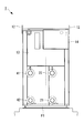
- FIG. 7 is a front view for explaining the appearance of the heat pump apparatus of FIG.
- FIG. 8 is a right side view for explaining the appearance of the heat pump apparatus of FIG.
- FIG. 9 is a left side view for explaining the appearance of the heat pump apparatus of FIG.
- FIG. 10 is a top view illustrating the appearance of the heat pump apparatus of FIG.
- the heat pump device 1 includes a condenser 2, an evaporator 4, a turbo compressor 5, a vertical main frame F2, a horizontal main frame F3, and a vertical sub-frame F4.
- an outer plate 13 that houses the transverse subframe F5 and the like is provided.
- a suspension portion 12 used when the heat pump device 1 is conveyed is exposed to the outside of the upper portion of the heat pump device 1.
- the suspension part 12 is a member fixed to the upper end of the vertical main frame F2, and the force acting on the suspension part 12 when the heat pump device 1 is lifted is transmitted to the horizontal main frame F3 and the base part via the vertical main frame F2. Is transmitted to F1.
- a heat source water inlet 41, a heat source water outlet 42, and hot water are provided below one end side (right end side in FIG. 7) of the heat pump device 1.
- the inlet 21 and the hot water outlet 22 protrude outside.
- a power supply box 14 to which power is supplied from the outside is disposed above one end side.
- the electric power supplied to the power supply box 14 is used for the operation of the heat pump device 1, and in particular, supplied to the electric motor 51 via the inverter unit 6.
- the operation panel 11 is exposed to the outside below the other end side (left end side in FIG. 7) of the heat pump device 1.
- the high-temperature and high-pressure gas refrigerant compressed by the turbo compressor 5 is discharged from the discharge portion of the turbo compressor 5 and flows into the oil mist separation tank 7.
- the mist of lubricating oil contained in the refrigerant is separated from the refrigerant.
- the refrigerant from which the mist of lubricating oil is separated flows from the oil mist separation tank 7 into the condenser 2.
- heat is exchanged between the high-temperature refrigerant and hot water supplied from outside, for example, about 75 ° C.
- the high-temperature refrigerant is condensed and liquefied by releasing heat into the hot water.
- the hot water absorbs heat from the high-temperature refrigerant, becomes hot water of about 80 ° C., for example, and flows out of the condenser 2 to the outside.
- the refrigerant liquefied by the condenser 2 flows out of the condenser 2 and flows into the intercooler 9.
- the intercooler 9 a part of the refrigerant that has flowed in is branched and adiabatically expanded to generate a low-temperature and low-pressure refrigerant. Then, heat exchange is performed between the divided low-temperature refrigerant and the other refrigerant, and the other refrigerant is further cooled.
- the diverted refrigerant is used for cooling other refrigerants and then flows into the suction portion of the turbo compressor 5.
- the refrigerant cooled by the intercooler 9 flows toward the expansion valve 3 and is adiabatically expanded when passing through the expansion valve 3 to become a low-temperature and low-pressure liquid refrigerant.
- the adiabatically expanded refrigerant flows into the evaporator 4.
- heat exchange is performed between a low-temperature refrigerant and heat source water supplied from outside, for example, at about 45 ° C.
- the low-temperature refrigerant evaporates and vaporizes by absorbing heat from the heat source water.
- the heat source water dissipates heat to the low-temperature refrigerant to become, for example, about 40 ° C. heat source water and flows out of the evaporator 4.
- the evaporated gas refrigerant flows into the accumulator 10 from the evaporator 4.
- the liquid refrigerant that has flowed out of the evaporator 4 together with the gas refrigerant is separated from the gas refrigerant, and only the gas refrigerant flows out of the accumulator 10.
- the gas refrigerant from which the liquid refrigerant has been separated in the accumulator 10 flows into the suction portion of the turbo compressor 5, is compressed by the turbo compressor 5, and is again discharged as high-pressure refrigerant from the discharge portion, and the above cycle is repeated. .
- lubricating oil is supplied to the turbo compressor 5 from the oil tank 8, and the lubricating oil is used for lubricating the sliding portion in the turbo compressor 5.
- the lubricating oil used for the lubrication is returned from the turbo compressor 5 to the oil tank 8 and supplied again from the oil tank 8 to the turbo compressor 5.
- a part of the lubricating oil used for lubrication in the turbo compressor 5 flows out toward the oil mist separation tank 7 together with the refrigerant.
- the lubricating oil that has flowed out is separated from the refrigerant in the oil mist separation tank 7.
- the lubricating oil separated from the refrigerant is returned from the oil mist separation tank 7 to the oil tank 8.
- the plate type heat exchanger which can be formed in a rectangular parallelepiped shape as the condenser 2 and the evaporator 4
- positioning the other component in the heat pump apparatus 1 a condenser is arranged. 2 and the evaporator 4 and other components are less likely to generate a gap. Therefore, an increase in installation area and volume in the heat pump device 1 can be suppressed. Specifically, by placing the condenser 2 and the evaporator 4 having a larger volume than other components side by side, it is easy to prevent an increase in the installation area in the heat pump device 1.
- the accumulator 10 above the condenser 2, when the heat pump device 1 is stopped, the refrigerant accumulated in the accumulator 10 flows into the evaporator 4, so that the refrigerant accumulates in the accumulator 10. Can be prevented.
Abstract
設置面積や体積の増加を抑制することができるヒートポンプ装置を提供する。冷媒を圧縮するターボ圧縮機(5)と、圧縮された冷媒を液化させる凝縮器(2)と、液化された冷媒を蒸発させる蒸発器(4)と、が設けられたヒートポンプ装置(1)において、凝縮器(2)および蒸発器(4)は、直方体状に形成されたプレート式熱交換器であり、プレート式熱交換器である凝縮器(2)とプレート式熱交換器である蒸発器(4)とが並んで配置されている。
Description
本発明は、ヒートポンプ装置、特にターボ冷凍機を用いたヒートポンプ装置に関する。
例えば、ヒートポンプ装置に用いられるターボ冷凍機における熱交換器としては、シェルアンドチューブ式の熱交換器が用いられている。そして、当該熱交換器の上部、もしくは、側面に圧縮機が配置されるのが一般的であった(例えば、特許文献1参照。)。
その一方で、一般にシェルアンドチューブ式の熱交換器は円筒形の容器であり、高圧冷媒が貯留される容器として、その薄肉化を図るには有利な形状であることが知られている。
しかしながら、ヒートポンプ装置における構成要素の配置を考える場合には、円筒形容器の周囲に活用できない空間、つまり隙間が発生しやすい。そのため、ヒートポンプ装置の設置面積や、体積を増加させやすいという問題があった。
本発明は、上記の課題を解決するためになされたものであって、設置面積や体積の増加を抑制することができるヒートポンプ装置を提供することを目的とする。
上記目的を達成するために、本発明は、以下の手段を提供する。
本発明のヒートポンプ装置は、冷媒を圧縮するターボ圧縮機と、圧縮された冷媒を液化させる凝縮器と、液化された冷媒を蒸発させる蒸発器と、が設けられたヒートポンプ装置であって、前記凝縮器および前記蒸発器は、プレート式熱交換器である。
本発明のヒートポンプ装置は、冷媒を圧縮するターボ圧縮機と、圧縮された冷媒を液化させる凝縮器と、液化された冷媒を蒸発させる蒸発器と、が設けられたヒートポンプ装置であって、前記凝縮器および前記蒸発器は、プレート式熱交換器である。
本発明によれば、直方体状に形成することができるプレート式熱交換器を用いることにより、ヒートポンプ装置における他の構成要素を配置する際に、凝縮器および蒸発器と、他の構成要素との間に隙間を発生させにくくなる。そのため、ヒートポンプ装置における設置面積や体積の増加を抑制することができる。
上記発明においては、前記ターボ圧縮機を駆動制御する制御部と、前記ターボ圧縮機から吐出された冷媒から潤滑油を分離する油分離部と、前記蒸発器から流出した冷媒が流入し、気体冷媒と液体冷媒とを分離し、該気体冷媒のみを前記蒸発器に供給する気液分離部と、が設けられ、前記凝縮器および前記蒸発器が並べて配置されるとともに、前記油分離部が、前記凝縮器および前記蒸発器と同一平面上に配置され、前記蒸発器および前記蒸発器の一方の上方に前記制御部が配置され、前記凝縮器および前記蒸発器の他方の上方に前記気液分離部が配置され、前記油分離部の上方に前記ターボ圧縮機が配置されていることが望ましい。
この構成によれば、他の構成要素と比較して体積が大きな凝縮器および蒸発器を並べて置くことにより、ヒートポンプ装置における設置面積の増大を防止することができる。
その一方で、制御部を凝縮器および蒸発器の一方の上方に配置することで、制御部を冷却する空気の流路を確保することが容易となる。
さらに、気液分離部を凝縮器および蒸発器の他方の上方に配置することにより、ヒートポンプ装置を停止した際に、気液分離部の内部の冷媒が蒸発器に流入するため、気液分離部に冷媒が溜まることを防止することができる。
油分離部の上方にターボ圧縮機を配置すること、言い換えると、ターボ圧縮機の下方に油分離部を配置することにより、ヒートポンプ装置を停止した際に、ターボ圧縮機の内部の冷媒が油分離部に流入するため、ターボ圧縮機に冷媒が溜まることを防止することができる。
本発明のヒートポンプ装置によれば、直方体状に形成することができるプレート式熱交換器を用いることにより、設置面積や体積の増加を抑制することができるという効果を奏する。
この発明の一実施形態に係るヒートポンプ装置について、図1から図10を参照して説明する。
図1は、本実施形態に係るヒートポンプ装置における回路構成を説明する模式図である。
ヒートポンプ装置1は、略直方体状に構成されたものであって、熱源水の供給を受け、温水を供給するものである。
ヒートポンプ装置1には、図1に示すように、凝縮器2と、膨張弁3と、蒸発器4と、ターボ圧縮機5と、インバータ部(制御部)6と、油ミスト分離タンク(油分離部)7と、油タンク8と、が主に設けられている。
図1は、本実施形態に係るヒートポンプ装置における回路構成を説明する模式図である。
ヒートポンプ装置1は、略直方体状に構成されたものであって、熱源水の供給を受け、温水を供給するものである。
ヒートポンプ装置1には、図1に示すように、凝縮器2と、膨張弁3と、蒸発器4と、ターボ圧縮機5と、インバータ部(制御部)6と、油ミスト分離タンク(油分離部)7と、油タンク8と、が主に設けられている。
図2は、図1のヒートポンプ装置の内部における配置を説明する正面図である。図3は、図2のヒートポンプ装置の内部における配置を説明する右側面図である。図4は、図2のヒートポンプ装置の内部における配置を説明する左側面図である。図5は、図2のヒートポンプ装置の内部における配置を説明する上面図である。図6は、図2のヒートポンプ装置の内部における配置を説明する背面図である。
凝縮器2は、略直方体状に形成されたプレート式熱交換器であって、ターボ圧縮機5から吐出された高温高圧の冷媒を冷却して凝縮させるものである。言い換えると、冷媒と温水との間で熱交換を行い、冷媒を液化させるとともに、温水を加熱するものである。凝縮器2は、一方の端部が油ミスト分離タンク7を介してターボ圧縮機5の吐出部と冷媒が流通可能に接続され、他方の端部が中間冷却器9を介して膨張弁3と冷媒が流通可能に接続されている。
凝縮器2は、図3および図6に示すように、長方形状に構成されたベース部F1の長手方向(図6の左右方向)における一方の端部側(図6における左端部側)であって、背面側(図3における右側)の端部に配置され、蒸発器4と並んで配置されている。
言い換えると、凝縮器2は、ベース部F1の上方、かつ、アキュムレータ10の下方であって、油ミスト分離タンク7と上述の長手方向に隣接する位置に配置されているとともに、蒸発器4と長手方向と直交する方向に隣接する位置に配置されている。
凝縮器2における一方の端部側の側面には、凝縮器2により加熱される前の温水が流入する温水入口21が下方に、凝縮器2により加熱されたあとの温水が流出する温水出口22が上方に設けられている。
中間冷却器9は、略円柱状に形成された凝縮器2から流出した冷媒をさらに冷却する熱交換器である。中間冷却器9における一方の端部は、凝縮器2と冷媒が流通可能に接続され、他方の端部は、膨張弁3と冷媒が流通可能に接続されている。
本実施形態では、中間冷却器9において、凝縮器2から流出した冷媒の一部を断熱膨張させて低温低圧とした冷媒と、膨張弁3に供給される冷媒との間で熱交換が行われる例に適用して説明する。この場合、膨張弁3の冷却に用いられた冷媒は、ターボ圧縮機5に流入する。
なお、中間冷却器9の構成としては公知の構成を用いることができ、特に限定するものではない。
なお、中間冷却器9の構成としては公知の構成を用いることができ、特に限定するものではない。
中間冷却器9は、図2から図5に示すように、ヒートポンプ装置1の中段における一方の端部側(図2の右端部側)であって、正面側(図3の左側)の端部に配置されている。
言い換えると、中間冷却器9は、蒸発器4の上方、かつ、インバータ部6の下方であって、油タンク8と長手方向に隣接するとともに、アキュムレータ10と長手方向と直交する方向に隣接する位置に配置されている。
このようにすることで、中間冷却器9を蒸発器4の上方に配置することにより、ヒートポンプ装置1が停止した際に、中間冷却器9の内部の冷媒は蒸発器4に流入するため、中間冷却器9に冷媒が溜まることを防止することができる。
膨張弁3は、中間冷却器9を介して凝縮器2から供給された冷媒を断熱膨張させ、その圧力減圧させる弁である。膨張弁3の一方の端部は中間冷却器9と冷媒が流通可能に接続され、他方の端部は、蒸発器4と冷媒が流通可能に接続されている。
なお、膨張弁3としては、公知のものを用いることができ、特に限定するものではない。
なお、膨張弁3としては、公知のものを用いることができ、特に限定するものではない。
蒸発器4は、略直方体状に形成されたプレート式熱交換器であって、膨張弁3により断熱膨張された冷媒を蒸発させるものである。言い換えると、冷媒と熱源水との間で熱交換を行うことで、熱源水の熱を冷媒に与え、冷媒を気化させるものである。蒸発器4は、一方の端部が膨張弁3と冷媒が流通可能に接続され、他方の端部がアキュムレータ(気液分離部)10を介してターボ圧縮機5の吸入部に接続されている。
蒸発器4は、図2および図3に示すように、長方形状に構成されたベース部F1の長手方向(図2の左右方向)における一方の端部側(図2における右端部側)であって、正面側(図3における左側)に配置され、凝縮器2と並んで配置されている。さらに、蒸発器4は、凝縮器2と比較して、ヒートポンプ装置1の中央より(図2の左より)に配置されている。
言い換えると、蒸発器4は、ベース部F1の上方、かつ、中間冷却器9の下方であって、操作盤11と長手方向に隣接するとともに、凝縮器2および油ミスト分離タンク7と長手方向と直交する方向に隣接する位置に配置されている。
蒸発器4における一方の端部側の側面には、蒸発器4により吸熱される前の熱源水が流入する熱源水入口41が上方に、蒸発器4により吸熱されたあとの熱源水が流出する熱源水出口42が下方に設けられている。
操作盤11は、ヒートポンプ装置1における各種機器を制御する操作機器等が集積されたものであって、操作機器等を内部に収納する略直方体状の筐体を有している。
操作盤11は、図2,図4および図6に示すように、長方形状に構成されたベース部F1の長手方向における他方の端部側(図2における左端部側)配置されている。
操作盤11は、図2,図4および図6に示すように、長方形状に構成されたベース部F1の長手方向における他方の端部側(図2における左端部側)配置されている。
言い換えると、操作盤11は、ベース部F1の上方、かつ、油タンク8の下方であって、蒸発器4および油ミスト分離タンク7と長手方向に隣接した位置に配置されている。
このようにすることで、操作盤11をヒートポンプ装置1における熱気がこもらない位置に配置することができる。
このようにすることで、操作盤11をヒートポンプ装置1における熱気がこもらない位置に配置することができる。
アキュムレータ10は、略円柱状に形成され、蒸発器4から流出した冷媒に含まれる液体冷媒と気体冷媒とを分離し、気体冷媒のみをターボ圧縮機5に供給するものである。アキュムレータ10における一方の端部は、蒸発器4と冷媒が流通可能に接続され、他方の端部は、ターボ圧縮機5と冷媒が流通可能に接続されている。
アキュムレータ10は、図3、図5および図6に示すように、ヒートポンプ装置1の上部(図6の上方)から中部にわたる位置における一方の端部側(図6の左端部側)であって、背面側(図5の上側)に配置されている。
言い換えると、アキュムレータ10は、凝縮器2の上方であって、ターボ圧縮機5と長手方向に隣接するとともに、中間冷却器9およびインバータ部6と長手方向と直交する方向に隣接する位置に配置されている。
なお、アキュムレータ10としては、公知のものを用いることができ、特に限定するものではい。
なお、アキュムレータ10としては、公知のものを用いることができ、特に限定するものではい。
ターボ圧縮機5は、アキュムレータ10を介して蒸発器4において気化した冷媒を吸入し、圧縮した後に油ミスト分離タンク7を介して凝縮器2に吐出するものである。ターボ圧縮機5における冷媒が流入する吸入部がアキュムレータ10を介して蒸発器4に接続され、冷媒が流出する吐出部が油ミスト分離タンク7を介して凝縮器2に接続されている。
ターボ圧縮機5は、回転駆動力を供給する電動機51と一体に構成され、電動機51は、インバータ部6から供給される電力により回転駆動されるとともに、回転速度が制御されている。
ターボ圧縮機5および電動機51は、図4から図6に示すように、ヒートポンプ装置1の上部(図6の上方)における他方の端部側(図6の右端部側)であって、背面側(図5の上側)に配置されている。
言い換えると、ターボ圧縮機5および電動機51は、油ミスト分離タンク7および油タンク8の上方であって、インバータ部6と長手方向に隣接する位置に配置されている。
なお、ターボ圧縮機5および電動機51としては、公知のものを用いることができ、特に限定するものではない。
なお、ターボ圧縮機5および電動機51としては、公知のものを用いることができ、特に限定するものではない。
インバータ部6は、電動機51に電力を供給するとともに、電動機51の回転速度を制御するものであって、略直方体状に形成された筐体を有するものである。
インバータ部6は、図2から図5に示すように、ヒートポンプ装置1の上部(図2の上方)における一方の端部側(図2の右端部側)であって、正面側(図5の下側)に配置されている。
インバータ部6は、図2から図5に示すように、ヒートポンプ装置1の上部(図2の上方)における一方の端部側(図2の右端部側)であって、正面側(図5の下側)に配置されている。
言い換えると、インバータ部6は、中間冷却器9の上方であって、アキュムレータ10、ターボ圧縮機5および電動機51と長手方向と直交する方向に隣接する位置に配置されている。
なお、インバータ部6としては、公知のものを用いることができ、特に限定するものではない。
なお、インバータ部6としては、公知のものを用いることができ、特に限定するものではない。
油ミスト分離タンク7は、略円柱状に形成され、ターボ圧縮機5から吐出された冷媒に含まれる潤滑油や、潤滑油のミストを、冷媒から分離するものである。油ミスト分離タンク7は、一方の端部がターボ圧縮機5の吐出部に冷媒が流通可能に接続され、他方の端部が凝縮器2に接続されている。
さらに、油ミスト分離タンク7は、冷媒から分離した潤滑油を油タンク8に供給するものでもある。
さらに、油ミスト分離タンク7は、冷媒から分離した潤滑油を油タンク8に供給するものでもある。
油ミスト分離タンク7は、図6に示すように、ベース部F1の長手方向における他方の端部側(図6における右端部側)であって、背面側の端部に配置されている。
言い換えると、油ミスト分離タンク7は、ベース部F1の上方、かつ、ターボ圧縮機5および電動機51の下方であって、蒸発器4と長手方向と直交する方向に隣接する位置に配置されている。
なお、油ミスト分離タンク7としては、公知のものを用いることができ、特に限定するものではない。
なお、油ミスト分離タンク7としては、公知のものを用いることができ、特に限定するものではない。
油タンク8は、略円柱状に形成され、ターボ圧縮機5の潤滑に用いられる潤滑油を貯留するとともに、ターボ圧縮機5に潤滑油を供給し、かつ、ターボ圧縮機5から排出された潤滑油が流入するものである。油タンク8は、ターボ圧縮機5との間で潤滑油の供給および受取が可能に接続されているとともに、油ミスト分離タンク7から潤滑油が供給されるように接続されている。
油タンク8は、図2、および、図4から図6に示すように、ヒートポンプ装置1の中段であって、他方の端部側(図2の左端部側)に配置されている。
言い換えると、油タンク8は、操作盤11の上方、かつ、電動機51の下方であって、中間冷却器9と長手方向に隣接する位置に配置されている。
このようにすることで、ターボ圧縮機5から油タンク8に潤滑油が戻りやすくなる。
言い換えると、油タンク8は、操作盤11の上方、かつ、電動機51の下方であって、中間冷却器9と長手方向に隣接する位置に配置されている。
このようにすることで、ターボ圧縮機5から油タンク8に潤滑油が戻りやすくなる。
さらに、ヒートポンプ装置1には、図2から図6に示すように、凝縮器2や、蒸発器4や、ターボ圧縮機5や、インバータ部6などを支持するベース部F1と、縦主フレームF2と、横主フレームF3と、縦副フレームF4と、横副フレームF5と、が設けられている。
ベース部F1は、ヒートポンプ装置1を構成する他の全ての構成要素を支持する部材であって、金属から形成された棒状の部材を略長方形状に組み合わせたものである。
ベース部F1の上面には、図2から図6に示すように、凝縮器2、蒸発器4、油ミスト分離タンク7、および、操作盤11が配置されているとともに、複数の縦主フレームF2および縦副フレームF4が取り付けられている。
ベース部F1の上面には、図2から図6に示すように、凝縮器2、蒸発器4、油ミスト分離タンク7、および、操作盤11が配置されているとともに、複数の縦主フレームF2および縦副フレームF4が取り付けられている。
縦主フレームF2は、ベース部F1からヒートポンプ装置1の上端まで延びる棒状の部材であり、ヒートポンプ装置1を吊り上げた際に、横主フレームF3およびベース部F1とともに他の構成要素を支持するものである。
縦主フレームF2は、図2から図6に示すように、ベース部F1における一対の長辺にそれぞれ2本ずつ、かつ、各長辺の中央から所定の距離だけ離れた位置に配置されている。
さらに、4本の縦主フレームF2それぞれの上端には吊り部12が設けられている。
縦主フレームF2は、図2から図6に示すように、ベース部F1における一対の長辺にそれぞれ2本ずつ、かつ、各長辺の中央から所定の距離だけ離れた位置に配置されている。
さらに、4本の縦主フレームF2それぞれの上端には吊り部12が設けられている。
横主フレームF3は、縦主フレームF2の間をベース部F1における短辺に沿って延び、一の長辺に配置された縦主フレームF2と、他の長辺に配置された縦主フレームF2とを接続する棒状の部材である。言い換えると、横主フレームF3は、縦主フレームF2とともに梯子状の構造を構成するものである。
さらに、横主フレームF3は、縦主フレームF2とともに、インバータ部6、ターボ圧縮機5、電動機51、および、油タンク8を支持するものでもある。
さらに、横主フレームF3は、縦主フレームF2とともに、インバータ部6、ターボ圧縮機5、電動機51、および、油タンク8を支持するものでもある。
具体的には、一の長辺に配置された縦主フレームF2と、他の長辺に配置された縦主フレームF2との間に2本の横主フレームF3が配置されている。つまり、ヒートポンプ装置1全体としては4本の横主フレームF3が設けられている。
上方の横主フレームF3は、インバータ部6、ターボ圧縮機5および電動機51の下方、かつ、中間冷却器9の上方に配置されている。下方の横主フレームF3は、中間冷却器9の下方、かつ、蒸発器4および凝縮器2の上方に配置されている。
縦副フレームF4は、横副フレームF5とともにアキュムレータ10および中間冷却器9などを支持するものである。縦副フレームF4は、ベース部F1から上方に向かって延びる棒状の部材であって、凝縮器2および蒸発器4の上方、かつ、アキュムレータ10および中間冷却器9の下方の空間まで延びている。
横副フレームF5は、縦副フレームF4とともにアキュムレータ10および中間冷却器9などを支持するものである。縦副フレームF4は、縦副フレームF4に対して略直交する方向に延びる棒状の部材であって、凝縮器2および蒸発器4の上方、かつ、アキュムレータ10および中間冷却器9の下方の空間に配置されたものである。
図7は、図1のヒートポンプ装置の外観を説明する正面図である。図8は、図7のヒートポンプ装置の外観を説明する右側面図である。図9は、図7のヒートポンプ装置の外観を説明する左側面図である。図10は、図7のヒートポンプ装置の外観を説明する上面図である。
さらに、ヒートポンプ装置1には、図7から図10に示すように、凝縮器2や、蒸発器4や、ターボ圧縮機5や、縦主フレームF2や、横主フレームF3や、縦副フレームF4や、横副フレームF5などを内部に収納する外板13が設けられている。
ヒートポンプ装置1の上部には、図7から図9に示すように、ヒートポンプ装置1を搬送する際に用いられる吊り部12が、外部に露出されている。吊り部12は、縦主フレームF2の上端に固定された部材であり、ヒートポンプ装置1を吊り上げた際に吊り部12に働く力は、縦主フレームF2を介して、横主フレームF3およびベース部F1に伝達される。
その一方で、図7,図8および図10に示すように、ヒートポンプ装置1の一方の端部側(図7の右端部側)の下方には、熱源水入口41、熱源水出口42、温水入口21、および、温水出口22が外部に突出している。
さらに、一方の端部側の上方には、外部から電力が供給される電源箱14が配置されている。電源箱14に供給された電力はヒートポンプ装置1の運転に用いられ、特に、インバータ部6を介して電動機51に供給される。
その一方で、図9に示すように、ヒートポンプ装置1の他方の端部側(図7の左端部側)の下方には、操作盤11が外部に露出されている。
次に、上記の構成からなるヒートポンプ装置における温水の供給について、図1などを参照しながら説明する。
ヒートポンプ装置1から温水を供給する場合には、外部からインバータ部6に電力が供給され、インバータ部6により電動機51が回転駆動され、ターボ圧縮機5が冷媒の圧縮を行う。
ヒートポンプ装置1から温水を供給する場合には、外部からインバータ部6に電力が供給され、インバータ部6により電動機51が回転駆動され、ターボ圧縮機5が冷媒の圧縮を行う。
ターボ圧縮機5により圧縮された高温高圧の気体冷媒は、ターボ圧縮機5の吐出部から吐出され、油ミスト分離タンク7に流入する。油ミスト分離タンク7では、冷媒に含まれる潤滑油のミストが、冷媒から分離される。潤滑油のミストが分離された冷媒は、油ミスト分離タンク7から凝縮器2に流入する。
凝縮器2では、高温の冷媒と、外部から供給された、例えば約75℃の温水との間で熱交換が行われる。高温の冷媒は温水に熱を放出することにより、凝縮して液化する。その一方で、温水は、高温の冷媒から熱を吸収して、例えば約80℃の温水となり、凝縮器2から外部に流出する。
凝縮器2で液化した冷媒は、凝縮器2から流出して中間冷却器9に流入する。中間冷却器9では、流入した冷媒の一部を分流し、断熱膨張させて低温低圧の冷媒を生成する。そして、分流された低温の冷媒と、その他の冷媒との間で熱交換を行い、その他の冷媒をさらに冷却する。
分流された冷媒は、その他の冷媒の冷却に用いられた後、ターボ圧縮機5の吸入部に流入する。
分流された冷媒は、その他の冷媒の冷却に用いられた後、ターボ圧縮機5の吸入部に流入する。
中間冷却器9により冷却された冷媒は膨張弁3に向かって流れ、膨張弁3を通過する際に断熱膨張され、低温低圧の液体冷媒となる。断熱膨張された冷媒は、蒸発器4に流入する。
蒸発器4では、低温の冷媒と、外部から供給された、例えば約45℃の熱源水との間で熱交換が行われる。低温の冷媒は、熱源水から熱を吸収することにより、蒸発して気化する。その一方で、熱源水は、低温の冷媒に放熱して、例えば約40℃の熱源水となり、蒸発器4の外部に流出する。
蒸発した気体冷媒は、蒸発器4からアキュムレータ10に流入する。アキュムレータ10では、気体冷媒とともに蒸発器4から流出した液体冷媒が、気体冷媒から分離され、気体冷媒のみがアキュムレータ10から流出する。
アキュムレータ10において液体冷媒が分離された気体冷媒は、ターボ圧縮機5の吸入部に流入し、ターボ圧縮機5により圧縮され、再び、吐出部から高圧の冷媒として吐出され、上述のサイクルが繰り返される。
その一方で、ターボ圧縮機5には、油タンク8から潤滑油が供給され、潤滑油はターボ圧縮機5における摺動部の潤滑に用いられる。潤滑に用いられた潤滑油は、ターボ圧縮機5から油タンク8に戻され、再び、油タンク8からターボ圧縮機5に供給される。
ここで、ターボ圧縮機5において潤滑に用いられた潤滑油の一部は、冷媒とともに油ミスト分離タンク7に向かって流出する。流出した潤滑油は、油ミスト分離タンク7において冷媒と分離される。冷媒から分離された潤滑油は、油ミスト分離タンク7から油タンク8に戻される。
上記の構成によれば、直方体状に形成することができるプレート式熱交換器を、凝縮器2および蒸発器4として用いることにより、ヒートポンプ装置1における他の構成要素を配置する際に、凝縮器2および蒸発器4と、他の構成要素との間に隙間を発生させにくくなる。そのため、ヒートポンプ装置1における設置面積や体積の増加を抑制することができる。
具体的には、他の構成要素と比較して体積が大きな凝縮器2および蒸発器4を並べて置くことにより、ヒートポンプ装置1における設置面積の増大を防止しやすくなる。
具体的には、他の構成要素と比較して体積が大きな凝縮器2および蒸発器4を並べて置くことにより、ヒートポンプ装置1における設置面積の増大を防止しやすくなる。
その一方で、インバータ部6を蒸発器4の上方に配置することで、インバータ部6を冷却する空気の流路を確保することが容易となる。
さらに、アキュムレータ10を凝縮器2の上方に配置することにより、ヒートポンプ装置1を停止した際に、アキュムレータ10の内部に溜まった冷媒が蒸発器4に流入するため、アキュムレータ10に冷媒が溜まることを防止することができる。
油ミスト分離タンク7の上方にターボ圧縮機5を配置すること、言い換えると、ターボ圧縮機5の下方に油ミスト分離タンク7を配置することにより、ヒートポンプ装置1を停止した際に、ターボ圧縮機5の内部の冷媒が油ミスト分離タンク7に流入するため、ターボ圧縮機5に冷媒が溜まることを防止することができる。
1 ヒートポンプ装置
2 凝縮器
4 蒸発器
5 ターボ圧縮機
6 インバータ部(制御部)
7 油ミスト分離タンク(油分離部)
10 アキュムレータ(気液分離部)
2 凝縮器
4 蒸発器
5 ターボ圧縮機
6 インバータ部(制御部)
7 油ミスト分離タンク(油分離部)
10 アキュムレータ(気液分離部)
Claims (2)
- 冷媒を圧縮するターボ圧縮機と、
圧縮された冷媒を液化させる凝縮器と、
液化された冷媒を蒸発させる蒸発器と、
が設けられたヒートポンプ装置であって、
前記凝縮器および前記蒸発器は、プレート式熱交換器であるヒートポンプ装置。 - 前記ターボ圧縮機を駆動制御する制御部と、
前記ターボ圧縮機から吐出された冷媒から潤滑油を分離する油分離部と、
前記蒸発器から流出した冷媒が流入し、気体冷媒と液体冷媒とを分離し、該気体冷媒のみを前記蒸発器に供給する気液分離部と、
が設けられ、
前記凝縮器および前記蒸発器が並べて配置されるとともに、前記油分離部が、前記凝縮器および前記蒸発器と同一平面上に配置され、
前記蒸発器および前記蒸発器の一方の上方に前記制御部が配置され、
前記凝縮器および前記蒸発器の他方の上方に前記気液分離部が配置され、
前記油分離部の上方に前記ターボ圧縮機が配置されている請求項1記載のヒートポンプ装置。
Priority Applications (2)
| Application Number | Priority Date | Filing Date | Title |
|---|---|---|---|
| EP10750810A EP2407736A4 (en) | 2009-03-12 | 2010-03-09 | HEAT PUMP DEVICE |
| US13/063,637 US20110185765A1 (en) | 2009-03-12 | 2010-03-09 | Heat pump apparatus |
Applications Claiming Priority (2)
| Application Number | Priority Date | Filing Date | Title |
|---|---|---|---|
| JP2009060177A JP5386201B2 (ja) | 2009-03-12 | 2009-03-12 | ヒートポンプ装置 |
| JP2009-060177 | 2009-03-12 |
Publications (1)
| Publication Number | Publication Date |
|---|---|
| WO2010104057A1 true WO2010104057A1 (ja) | 2010-09-16 |
Family
ID=42728346
Family Applications (1)
| Application Number | Title | Priority Date | Filing Date |
|---|---|---|---|
| PCT/JP2010/053842 WO2010104057A1 (ja) | 2009-03-12 | 2010-03-09 | ヒートポンプ装置 |
Country Status (4)
| Country | Link |
|---|---|
| US (1) | US20110185765A1 (ja) |
| EP (1) | EP2407736A4 (ja) |
| JP (1) | JP5386201B2 (ja) |
| WO (1) | WO2010104057A1 (ja) |
Cited By (3)
| Publication number | Priority date | Publication date | Assignee | Title |
|---|---|---|---|---|
| JP2012127551A (ja) * | 2010-12-14 | 2012-07-05 | Corona Corp | ヒートポンプ装置 |
| JP2013007370A (ja) * | 2011-06-27 | 2013-01-10 | Ihi Corp | 廃熱発電装置 |
| JP2013113555A (ja) * | 2011-11-30 | 2013-06-10 | Mitsubishi Heavy Ind Ltd | ターボ冷凍機 |
Families Citing this family (7)
| Publication number | Priority date | Publication date | Assignee | Title |
|---|---|---|---|---|
| JP5737918B2 (ja) * | 2010-12-03 | 2015-06-17 | 三菱重工業株式会社 | 生物処理方式による排水処理設備用ヒートポンプシステム、及びこれを備えた生物処理方式による排水処理設備、並びに、生物処理方式による排水処理設備用ヒートポンプシステムの制御方法 |
| US20130255308A1 (en) * | 2012-03-29 | 2013-10-03 | Johnson Controls Technology Company | Chiller or heat pump with a falling film evaporator and horizontal oil separator |
| JP6381890B2 (ja) | 2013-10-25 | 2018-08-29 | 三菱重工サーマルシステムズ株式会社 | 冷媒循環装置、冷媒循環方法および異性化抑制方法 |
| JP6138957B2 (ja) | 2013-10-25 | 2017-05-31 | 三菱重工業株式会社 | 冷媒循環装置、冷媒循環方法および酸抑制方法 |
| CN106871501A (zh) | 2015-12-10 | 2017-06-20 | 开利公司 | 一种经济器及具有其的制冷系统 |
| JP7313796B2 (ja) * | 2018-01-12 | 2023-07-25 | 三菱重工サーマルシステムズ株式会社 | 熱交換ユニット |
| US20230117931A1 (en) * | 2021-10-15 | 2023-04-20 | Hamilton Sundstrand Corporation | Integrated supplemental cooling unit |
Citations (7)
| Publication number | Priority date | Publication date | Assignee | Title |
|---|---|---|---|---|
| JPH024164U (ja) * | 1988-06-20 | 1990-01-11 | ||
| JPH08285401A (ja) * | 1995-04-13 | 1996-11-01 | Pado:Kk | 蒸気圧縮機を用いた冷温水供給装置 |
| JPH10267427A (ja) * | 1997-03-25 | 1998-10-09 | Mitsubishi Electric Corp | 冷却装置 |
| JP2000018735A (ja) * | 1998-06-23 | 2000-01-18 | Kobe Steel Ltd | 冷凍装置 |
| JP2000292011A (ja) | 1999-04-01 | 2000-10-20 | Ebara Corp | ターボ冷凍機 |
| JP2002364936A (ja) * | 2001-06-08 | 2002-12-18 | Kobe Steel Ltd | 冷凍装置 |
| JP2007255831A (ja) * | 2006-03-24 | 2007-10-04 | Daikin Ind Ltd | アキュムレータ及び冷凍装置 |
Family Cites Families (11)
| Publication number | Priority date | Publication date | Assignee | Title |
|---|---|---|---|---|
| FR2474151A1 (fr) * | 1980-01-21 | 1981-07-24 | Inst Francais Du Petrole | Procede de production de chaleur au moyen d'une pompe a chaleur utilisant un melange specifique de fluides comme agent de travail |
| NZ212762A (en) * | 1984-07-24 | 1988-01-08 | Conry Ronald D | Modular refrigeration system: separate, couplable refrigeration units |
| US4843837A (en) * | 1986-02-25 | 1989-07-04 | Technology Research Association Of Super Heat Pump Energy Accumulation System | Heat pump system |
| US4811568A (en) * | 1988-06-24 | 1989-03-14 | Ram Dynamics, Inc. | Refrigeration sub-cooler |
| ES2150527T3 (es) * | 1994-03-15 | 2000-12-01 | Mitsubishi Electric Corp | Sistema de aire acondicionado. |
| GB9426208D0 (en) * | 1994-12-23 | 1995-02-22 | British Tech Group Usa | Plate heat exchanger |
| US5839295A (en) * | 1997-02-13 | 1998-11-24 | Frontier Refrigeration And Air Conditioning Ltd. | Refrigeration/heat pump module |
| US7353662B2 (en) * | 2004-12-22 | 2008-04-08 | York International Corporation | Medium voltage starter for a chiller unit |
| JP2007139262A (ja) * | 2005-11-16 | 2007-06-07 | Kimura Kohki Co Ltd | 水冷ヒートポンプ式空調機 |
| KR101198457B1 (ko) * | 2006-09-01 | 2012-11-06 | 엘지전자 주식회사 | 수냉식 공기조화기 |
| EP4349694A2 (en) * | 2007-01-31 | 2024-04-10 | The Chemours Company FC, LLC | A vapor compression heat transfer system |
-
2009
- 2009-03-12 JP JP2009060177A patent/JP5386201B2/ja active Active
-
2010
- 2010-03-09 EP EP10750810A patent/EP2407736A4/en not_active Withdrawn
- 2010-03-09 US US13/063,637 patent/US20110185765A1/en not_active Abandoned
- 2010-03-09 WO PCT/JP2010/053842 patent/WO2010104057A1/ja active Application Filing
Patent Citations (7)
| Publication number | Priority date | Publication date | Assignee | Title |
|---|---|---|---|---|
| JPH024164U (ja) * | 1988-06-20 | 1990-01-11 | ||
| JPH08285401A (ja) * | 1995-04-13 | 1996-11-01 | Pado:Kk | 蒸気圧縮機を用いた冷温水供給装置 |
| JPH10267427A (ja) * | 1997-03-25 | 1998-10-09 | Mitsubishi Electric Corp | 冷却装置 |
| JP2000018735A (ja) * | 1998-06-23 | 2000-01-18 | Kobe Steel Ltd | 冷凍装置 |
| JP2000292011A (ja) | 1999-04-01 | 2000-10-20 | Ebara Corp | ターボ冷凍機 |
| JP2002364936A (ja) * | 2001-06-08 | 2002-12-18 | Kobe Steel Ltd | 冷凍装置 |
| JP2007255831A (ja) * | 2006-03-24 | 2007-10-04 | Daikin Ind Ltd | アキュムレータ及び冷凍装置 |
Non-Patent Citations (1)
| Title |
|---|
| See also references of EP2407736A4 |
Cited By (4)
| Publication number | Priority date | Publication date | Assignee | Title |
|---|---|---|---|---|
| JP2012127551A (ja) * | 2010-12-14 | 2012-07-05 | Corona Corp | ヒートポンプ装置 |
| JP2013007370A (ja) * | 2011-06-27 | 2013-01-10 | Ihi Corp | 廃熱発電装置 |
| JP2013113555A (ja) * | 2011-11-30 | 2013-06-10 | Mitsubishi Heavy Ind Ltd | ターボ冷凍機 |
| US9291378B2 (en) | 2011-11-30 | 2016-03-22 | Mitsubishi Heavy Industries, Ltd. | Simplified refrigeration leak detection structure for a turbo chiller |
Also Published As
| Publication number | Publication date |
|---|---|
| EP2407736A4 (en) | 2012-09-12 |
| US20110185765A1 (en) | 2011-08-04 |
| JP2010210224A (ja) | 2010-09-24 |
| EP2407736A1 (en) | 2012-01-18 |
| JP5386201B2 (ja) | 2014-01-15 |
Similar Documents
| Publication | Publication Date | Title |
|---|---|---|
| JP5386201B2 (ja) | ヒートポンプ装置 | |
| KR101633781B1 (ko) | 칠러 | |
| US9851130B2 (en) | Electronics cooling using lubricant return for a shell-and-tube style evaporator | |
| EP2019272B1 (en) | Combined receiver and heat exchanger for a secondary refrigerant | |
| EP2828590B1 (en) | Electronics cooling using lubricant return for a shell-and-tube style evaporator | |
| US10766340B2 (en) | Air conditioner system for vehicle | |
| JP2012240670A (ja) | 車両用コンデンサ及びこれを利用した車両用エアコンシステム | |
| JP5346343B2 (ja) | 二段圧縮ヒートポンプサイクル装置 | |
| JP2012116462A (ja) | 車両用コンデンサ | |
| EP2522844A2 (en) | Rankine cycle apparatus | |
| JP2008249209A (ja) | 冷凍装置 | |
| CN201858811U (zh) | 螺杆式液体冷却机组 | |
| KR101173157B1 (ko) | 수냉식 응축기 및 과냉각용 수냉식 열교환기를 구비하는 차량용 공조 시스템 | |
| JP2013200056A (ja) | 冷凍サイクル及び冷凍ショーケース | |
| CN104949397B (zh) | 涡轮制冷机的蒸发器以及具备该蒸发器的涡轮制冷机 | |
| WO2016103479A1 (ja) | 圧縮機用のガス回収システム、圧縮機システム及び冷凍サイクルシステム | |
| CN107532826B (zh) | 涡轮制冷装置 | |
| JP2008138895A (ja) | 蒸発器ユニット | |
| JP5582713B2 (ja) | ヒートポンプ装置 | |
| JP5529432B2 (ja) | ヒートポンプ装置 | |
| KR20090045473A (ko) | 응축기 | |
| US20180259232A1 (en) | Cooling system and cooling method | |
| JP2013108735A (ja) | 冷凍サイクル装置 | |
| JP2013217512A (ja) | エンジン駆動式ヒートポンプエアコン | |
| EP2856042B1 (en) | Energy recovery apparatus |
Legal Events
| Date | Code | Title | Description |
|---|---|---|---|
| 121 | Ep: the epo has been informed by wipo that ep was designated in this application |
Ref document number: 10750810 Country of ref document: EP Kind code of ref document: A1 |
|
| WWE | Wipo information: entry into national phase |
Ref document number: 2010750810 Country of ref document: EP |
|
| WWE | Wipo information: entry into national phase |
Ref document number: a201104618 Country of ref document: UA |
|
| WWE | Wipo information: entry into national phase |
Ref document number: 13063637 Country of ref document: US |
|
| NENP | Non-entry into the national phase |
Ref country code: DE |