WO2010090335A1 - 幾何変換動き補償予測を用いる動画像符号化装置及び動画像復号装置 - Google Patents
幾何変換動き補償予測を用いる動画像符号化装置及び動画像復号装置 Download PDFInfo
- Publication number
- WO2010090335A1 WO2010090335A1 PCT/JP2010/051903 JP2010051903W WO2010090335A1 WO 2010090335 A1 WO2010090335 A1 WO 2010090335A1 JP 2010051903 W JP2010051903 W JP 2010051903W WO 2010090335 A1 WO2010090335 A1 WO 2010090335A1
- Authority
- WO
- WIPO (PCT)
- Prior art keywords
- prediction
- geometric transformation
- block
- motion
- parameter
- Prior art date
- Legal status (The legal status is an assumption and is not a legal conclusion. Google has not performed a legal analysis and makes no representation as to the accuracy of the status listed.)
- Ceased
Links
Images


















Classifications
-
- H—ELECTRICITY
- H04—ELECTRIC COMMUNICATION TECHNIQUE
- H04N—PICTORIAL COMMUNICATION, e.g. TELEVISION
- H04N19/00—Methods or arrangements for coding, decoding, compressing or decompressing digital video signals
- H04N19/10—Methods or arrangements for coding, decoding, compressing or decompressing digital video signals using adaptive coding
- H04N19/169—Methods or arrangements for coding, decoding, compressing or decompressing digital video signals using adaptive coding characterised by the coding unit, i.e. the structural portion or semantic portion of the video signal being the object or the subject of the adaptive coding
- H04N19/17—Methods or arrangements for coding, decoding, compressing or decompressing digital video signals using adaptive coding characterised by the coding unit, i.e. the structural portion or semantic portion of the video signal being the object or the subject of the adaptive coding the unit being an image region, e.g. an object
-
- H—ELECTRICITY
- H04—ELECTRIC COMMUNICATION TECHNIQUE
- H04N—PICTORIAL COMMUNICATION, e.g. TELEVISION
- H04N19/00—Methods or arrangements for coding, decoding, compressing or decompressing digital video signals
- H04N19/10—Methods or arrangements for coding, decoding, compressing or decompressing digital video signals using adaptive coding
- H04N19/102—Methods or arrangements for coding, decoding, compressing or decompressing digital video signals using adaptive coding characterised by the element, parameter or selection affected or controlled by the adaptive coding
- H04N19/103—Selection of coding mode or of prediction mode
- H04N19/109—Selection of coding mode or of prediction mode among a plurality of temporal predictive coding modes
-
- H—ELECTRICITY
- H04—ELECTRIC COMMUNICATION TECHNIQUE
- H04N—PICTORIAL COMMUNICATION, e.g. TELEVISION
- H04N19/00—Methods or arrangements for coding, decoding, compressing or decompressing digital video signals
- H04N19/10—Methods or arrangements for coding, decoding, compressing or decompressing digital video signals using adaptive coding
- H04N19/134—Methods or arrangements for coding, decoding, compressing or decompressing digital video signals using adaptive coding characterised by the element, parameter or criterion affecting or controlling the adaptive coding
- H04N19/136—Incoming video signal characteristics or properties
- H04N19/14—Coding unit complexity, e.g. amount of activity or edge presence estimation
-
- H—ELECTRICITY
- H04—ELECTRIC COMMUNICATION TECHNIQUE
- H04N—PICTORIAL COMMUNICATION, e.g. TELEVISION
- H04N19/00—Methods or arrangements for coding, decoding, compressing or decompressing digital video signals
- H04N19/10—Methods or arrangements for coding, decoding, compressing or decompressing digital video signals using adaptive coding
- H04N19/169—Methods or arrangements for coding, decoding, compressing or decompressing digital video signals using adaptive coding characterised by the coding unit, i.e. the structural portion or semantic portion of the video signal being the object or the subject of the adaptive coding
- H04N19/17—Methods or arrangements for coding, decoding, compressing or decompressing digital video signals using adaptive coding characterised by the coding unit, i.e. the structural portion or semantic portion of the video signal being the object or the subject of the adaptive coding the unit being an image region, e.g. an object
- H04N19/176—Methods or arrangements for coding, decoding, compressing or decompressing digital video signals using adaptive coding characterised by the coding unit, i.e. the structural portion or semantic portion of the video signal being the object or the subject of the adaptive coding the unit being an image region, e.g. an object the region being a block, e.g. a macroblock
-
- H—ELECTRICITY
- H04—ELECTRIC COMMUNICATION TECHNIQUE
- H04N—PICTORIAL COMMUNICATION, e.g. TELEVISION
- H04N19/00—Methods or arrangements for coding, decoding, compressing or decompressing digital video signals
- H04N19/60—Methods or arrangements for coding, decoding, compressing or decompressing digital video signals using transform coding
- H04N19/61—Methods or arrangements for coding, decoding, compressing or decompressing digital video signals using transform coding in combination with predictive coding
Definitions
- the present invention relates to moving picture coding and moving picture decoding in which geometric transformation parameters are estimated using motion information of neighboring blocks and prediction target blocks, and geometric transformation prediction processing of the prediction target blocks is performed based on the estimated geometric transformation parameters. Relating to the device.
- H.264 ITU-T REC. H. In H.264 and ISO / IEC 14496-10 (hereinafter referred to as “H.264”), prediction processing, conversion processing, and entropy coding processing are performed in units of rectangular blocks (for example, 16 ⁇ 16 pixels, 8 ⁇ 8 pixels). Etc.). For this reason, H.C. In H.264, when an object that cannot be expressed by a rectangular block is predicted, the prediction efficiency is increased by selecting a smaller prediction block (4 ⁇ 4 pixels or the like). In order to predict such an object effectively, there are a method of preparing a plurality of prediction patterns in a rectangular block, a method of applying motion compensation using affine transformation to a deformed object, and the like.
- an object movement model is an affine transformation model, and an optimal affine transformation parameter is calculated for each prediction target block, thereby enlarging / reducing the object.
- An invention such as a video frame transfer method using a prediction that takes rotation into consideration is disclosed.
- Non-Patent Document 1 divides a block into triangular patches based on motion vector information calculated as a translation model as a motion model, and estimates an affine transformation parameter for each patch. A method of approximately performing motion compensation prediction of an affine transformation model is disclosed.
- Non-Patent Document 1 uses an affine transformation using motion vectors of eight types of adjacent blocks adjacent to a pixel block to be predicted, such as up, down, left, and right, and a motion vector calculated from the pixel block to be predicted.
- affine transformation using motion vectors of eight types of adjacent blocks adjacent to a pixel block to be predicted, such as up, down, left, and right, and a motion vector calculated from the pixel block to be predicted.
- the present invention has been invented in order to solve these problems in view of the above points.
- the present invention reduces the motion detection processing necessary for estimating the geometric transformation parameters used for the geometric transformation motion compensation prediction, and reduces the code amount.
- An object of the present invention is to provide a video encoding device, a video decoding device, a video encoding method, and a video decoding method that improve the prediction efficiency without increasing the image quality.
- the moving picture encoding apparatus of the present invention employs the following configuration.
- a moving image encoding apparatus includes a motion information acquisition unit that acquires motion information of one or more adjacent blocks among adjacent blocks adjacent to one of pixel blocks into which an image signal is divided, and motion for the pixel blocks
- a geometric transformation information acquisition unit that acquires, based on the motion information, a geometric transformation parameter that is information related to a shape of a mapping obtained by geometric transformation of the pixel block in a reference image signal when performing compensation, and the reference image signal
- a geometric transformation prediction unit that performs geometric transformation motion prediction including geometric transformation with the pixel block using the reference image signal subjected to geometric transformation by the geometric transformation parameter, and the geometric transformation motion prediction is performed.
- an encoding unit that encodes the prediction error value of the pixel block.
- the moving image coding method acquires motion information of one or more adjacent blocks among adjacent blocks adjacent to one of the pixel blocks into which the image signal is divided.
- Acquiring a geometric transformation parameter which is information relating to the shape of the mapping by the geometric transformation of the pixel block, in the reference image signal when performing the motion compensation for the pixel block, based on the motion information
- Geometric transformation information acquisition step and geometric transformation motion prediction including geometric transformation between the reference image signal and the pixel block are performed using the reference image signal subjected to geometric transformation by the geometric transformation parameter.
- a moving picture decoding apparatus includes a geometric transformation including a geometric transformation between a pixel block into which an image signal is divided and a reference image signal when motion compensation is performed on the pixel block.
- a decoding unit that decodes code data obtained by encoding the image signal, including a prediction error value obtained by conversion motion prediction, and a motion of one or more adjacent blocks among adjacent blocks adjacent to the pixel block
- a motion information acquisition unit that acquires information, and a geometric transformation information acquisition unit that acquires, based on the motion information, a geometric transformation parameter that is information related to a shape of a mapping by geometric transformation of the pixel block in the reference image signal;
- the geometric transformation motion prediction is performed using the reference image signal subjected to the geometric transformation by the geometric transformation parameter to generate a prediction value.
- a Department an adder for adding the said predicted value generated and decoded the prediction error values, can be configured to have.
- the moving picture decoding method provides a geometric conversion between a pixel block obtained by dividing an image signal and a reference image signal when motion compensation is performed on the pixel block.
- a motion information acquisition step for acquiring block motion information, and a geometric transformation information for obtaining a geometric transformation parameter, which is information relating to the shape of the mapping of the pixel block in the previous reference image signal, based on the motion information.
- An obtaining step and a geometric transformation motion prediction including a geometric transformation between the reference image signal and the pixel block according to the geometric transformation parameter.
- the motion detection process necessary for estimating the geometric transformation parameter used for the geometric transformation motion compensation prediction is reduced, and the prediction is performed without increasing the code amount. It is possible to provide a video encoding device and a video decoding device that improve efficiency.
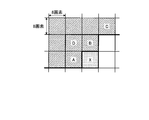
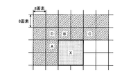
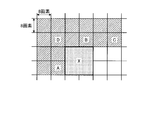
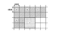
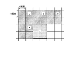
- the figure showing the positional relationship of the pixel block used as the object of an encoding or decoding, and an adjacent block The figure showing the positional relationship of an adjacent block in case the pixel block used as the object of an encoding or decoding is the upper left of a macroblock. The figure showing the positional relationship of an adjacent block in case the pixel block used as the object of an encoding or decoding is an upper right of a macroblock. The figure showing the positional relationship of an adjacent block in case the pixel block used as the object of an encoding or decoding is the lower left of a macroblock. The figure showing the positional relationship of an adjacent block in case the pixel block used as the object of an encoding or decoding is a lower right of a macroblock.
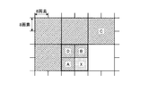
- the figure showing the positional relationship when the block size of an adjacent block is small with respect to the pixel block used as the object of an encoding or a decoding The figure showing the positional relationship when the block size of an adjacent block is small with respect to the pixel block used as the object of an encoding or a decoding. The figure showing the positional relationship when the block size of an adjacent block is small with respect to the pixel block used as the object of an encoding or a decoding. The figure showing the positional relationship when the block size of an adjacent block is small with respect to the pixel block used as the object of an encoding or a decoding.
- the flowchart which shows the flow of the process of the geometric transformation prediction shown in 1st Embodiment.
- the figure which shows a syntax structure The figure which shows the information contained in a slice header syntax.
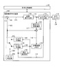
- the block diagram which shows the moving image encoder according to 2nd Embodiment.
- the first to seventh embodiments will be described with reference to the drawings.
- the first to fourth embodiments are embodiments using a moving image encoding device
- the fifth to seventh embodiments are embodiments using a moving image decoding device.
- “determination parameter” corresponds to “determination parameter”.
- the video encoding apparatus described in the following embodiment divides each frame constituting an input image signal into a plurality of pixel blocks, performs encoding processing on the divided pixel blocks, and performs compression encoding. It is a device that outputs a code string.
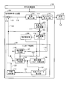
- FIG. 1 is a diagram illustrating a configuration of a moving image encoding apparatus 100 that realizes an encoding method using geometric transformation prediction.
- FIG. 2 is a block diagram of the inter prediction unit 130 included in the video encoding device 100.
- the moving image encoding apparatus 100 in FIG. 1 performs inter prediction (interframe prediction) encoding processing on the input image signal 114 based on the encoding parameter input from the encoding control unit 126, and generates the predicted image signal 123. Generate encoded data 124.
- inter prediction interframe prediction
- the moving image encoding apparatus 100 receives an input image signal 114 of a moving image or a still image divided into pixel blocks, for example, macro blocks.
- the input image signal is one encoding processing unit including both a frame and a field. In the present embodiment, an example in which a frame is used as one encoding processing unit will be described.
- the moving picture encoding apparatus 100 performs encoding in a plurality of prediction modes having different block sizes and generation methods of the predicted image signal 123.
- a method of generating the predicted image signal 123 for example, intra prediction (intraframe prediction) in which a predicted image is generated only within a frame to be encoded, and inter prediction in which prediction is performed using a plurality of temporally different reference frames. is there.
- intra prediction intraframe prediction
- inter prediction in which prediction is performed using a plurality of temporally different reference frames.
- the macro block is set to the basic processing block size of the encoding process.
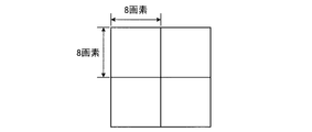
- the macroblock is typically a 16 ⁇ 16 pixel block shown in FIG. 3, for example, but may be a 32 ⁇ 32 pixel block unit or an 8 ⁇ 8 pixel block unit.
- the shape of the macroblock does not necessarily need to be a square lattice.
- the encoding target macroblock of the input image signal 114 is referred to as a “prediction target block”.
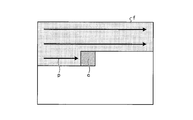
- the encoding process is performed from the upper left to the lower right as shown in FIG. 4 in order to simplify the description.
- the blocks located on the left and above the block c to be encoded are the encoded blocks p.
- the moving image coding apparatus 100 includes a subtractor 101, a transform / quantization unit 102, an inverse quantization / inverse transform unit 103, an adder 104, a reference image memory 105, a motion estimation unit 106, and an inter prediction unit 130. .
- the moving image encoding apparatus 100 is connected to the encoding control unit 126.
- the input image signal 114 is input to the subtractor 101.
- the subtracter 101 further receives a predicted image signal 123 corresponding to each prediction mode output from the inter prediction unit 130.
- the subtractor 101 calculates a prediction error signal 115 obtained by subtracting the prediction image signal 123 from the input image signal 114.
- the prediction error signal 115 is input to the transform / quantization unit 102.
- the transform / quantization unit 102 performs orthogonal transform such as discrete cosine transform (DCT) on the prediction error signal 115 to generate transform coefficients.
- DCT discrete cosine transform
- the transformation in the transformation / quantization unit 102 is H.264.
- discrete sine transform, wavelet transform, component analysis, or the like may be used.
- the transform / quantization unit 102 quantizes the transform coefficient in accordance with quantization information represented by a quantization parameter, a quantization matrix, and the like given by the encoding control unit 126.
- the transform / quantization unit 102 outputs the quantized transform coefficient 116 to the entropy coding unit 112 and also outputs it to the inverse quantization / inverse transform unit 103.
- the entropy encoding unit 112 performs entropy encoding, for example, Huffman encoding or arithmetic encoding, on the quantized transform coefficient 116.
- the entropy encoding unit 112 further performs entropy encoding on various encoding parameters used when the target block is encoded, including the prediction information output from the encoding control unit 126 and the like. Thereby, encoded data is generated.
- the encoding parameter is a parameter required for decoding prediction information, information on transform coefficients, information on quantization, and the like.
- the encoding parameter of the prediction target block is held in an internal memory of the encoding control unit 126, and is used when the prediction target block is used as an adjacent block of another pixel block.
- the encoded data 124 generated by the entropy encoding unit 112 is output from the moving image encoding apparatus 100, and after being multiplexed and temporarily stored in the output buffer 113, according to the output timing managed by the encoding control unit 126. Output as encoded data 124.
- the encoded data 124 is sent to, for example, a storage system (storage medium) or a transmission system (communication line) (not shown).
- the inverse quantization / inverse transform unit 103 performs an inverse quantization process on the quantized transform coefficient 116 output from the transform / quantization unit 102.
- the quantization information corresponding to the quantization information used in the transform / quantization unit 102 is loaded from the internal memory of the encoding control unit 126 and the inverse quantization process is performed.
- the quantization information is, for example, a parameter represented by a quantization parameter, a quantization matrix, or the like.
- the inverse quantization / inverse transform unit 103 further reproduces the decoded prediction error signal 117 by performing inverse orthogonal transform such as inverse discrete cosine transform (IDCT) on the transform coefficient after inverse quantization.
- inverse orthogonal transform such as inverse discrete cosine transform (IDCT)
- the decoded prediction error signal 117 is input to the adder 104.
- the adder 104 adds the decoded prediction error signal 117 and the predicted image signal 123 output from the inter prediction unit 130, thereby generating a decoded image signal 118.
- the decoded image signal 118 is a local decoded image signal.
- the decoded image signal 118 is stored as the reference image signal 120 in the reference image memory 105.
- the reference image signal 120 accumulated in the reference image memory 105 is output to the motion estimation unit 106, the inter prediction unit 130, etc., and is referred to when performing prediction.
- the motion estimation unit 106 uses the input image signal 114 and the reference image signal 120 to calculate a motion vector 119 suitable for the prediction target block.
- the motion information may be represented by a motion vector, for example.
- the motion information may be a predicted value when the motion vector is predicted by another motion vector or the like.
- the motion estimation unit 106 calculates the motion vector 119 by performing block matching between the prediction target block of the input image signal 114 and the interpolated image of the reference image signal 120.
- an evaluation criterion for matching for example, a value obtained by accumulating the difference between the input image signal 114 and the interpolated image after matching for each pixel is used.
- the motion vector 119 may be determined by using a value obtained by converting the difference between the predicted image and the original image, taking into account the magnitude of the motion vector, the code amount of the motion vector, and the like. Or may be determined. Moreover, you may utilize costs, such as Formula (29) and Formula (30) mentioned later. Further, the matching may be performed through a search within the matching range based on search range information provided from the outside of the moving image encoding apparatus 100, or may be performed hierarchically for each pixel accuracy.
- the motion vectors 119 calculated for the plurality of reference image signals in this way are input to the inter prediction unit 130 and used to generate the predicted image signal 123.
- the plurality of reference image signals are locally decoded images having different display times.
- the calculated motion vector 119 is output to the entropy encoding unit 112, and after entropy encoding is performed, it is multiplexed into encoded data.
- the motion vector 119 used for encoding the target pixel block is stored in the internal memory of the encoding control unit 126 and is appropriately loaded from the inter prediction unit 130 and used.
- ⁇ Inter prediction unit 130> 2 includes a motion compensation prediction unit 107, a geometric transformation parameter derivation unit 108, a geometric transformation prediction unit 109, a determination parameter derivation unit 127, a prediction separation switch 110, and a prediction switching unit 111.
- the motion compensation prediction unit 107 generates a prediction image signal 123 using the input motion vector 119 and the reference image signal 120.
- FIG. 5 is a diagram illustrating an example of inter prediction performed by the motion compensation prediction unit 107.
- a motion vector is acquired by acquiring a position with a small prediction error in the frame (t ⁇ 1) for the prediction target block included in the frame (t).
- interpolation processing is performed using a plurality of reference image signals 120 stored in the reference image memory 105, and the generated interpolated image and the input image signal 114 are based on the amount of deviation from the pixel block at the same position.
- a predicted image signal 123 is generated.
- interpolation processing for example, interpolation processing with 1/2 pixel accuracy, interpolation processing with 1/4 pixel accuracy, or the like is used.
- interpolation processing such as filtering processing on the reference image signal 120, interpolation pixel processing is performed.
- Generate a value For example, H.D. is allowed to perform interpolation processing up to 1/4 pixel accuracy for luminance signals.
- the shift amount is expressed by four times the integer pixel accuracy. This amount of deviation is called a motion vector.
- the motion compensated prediction unit 107 determines the position referenced by the motion vector 119 using the following equation (1) from the position of the prediction target block according to the information of the motion vector 119.
- H A description will be given taking an example of H.264 interpolation interpolation with 1/4 pixel accuracy.
- each component of the motion vector is a multiple of 4, it means that it is an integer pixel position. In other cases, it is a predicted position corresponding to an interpolation position with fractional accuracy.
- (x, y) is a vertical and horizontal index indicating the start position of the prediction target block
- (x_pos, y_pos) represents a corresponding prediction position of the reference image signal
- (Mv_x, mv_y) represents a motion vector having a 1/4 pixel accuracy.
- FIG. It is a figure which shows the example of a H.264 prediction pixel production
- alphabets indicated by capital letters indicate pixels at integer positions
- dot hatched squares indicate interpolation pixels at 1/2 pixel positions.
- hatched squares indicate interpolation pixels corresponding to 1/4 pixel positions.
- the interpolation processing of 1/2 pixel corresponding to the positions of alphabets b and h is calculated by the following equation.
- an interpolation pixel at a 1/2 pixel position is generated using a 6-tap FIR filter (tap coefficients: (1, -5, 20, 20, -5, 1) / 32).
- the interpolation pixel at the 1/4 pixel position is calculated using a 2-tap average value filter (tap coefficient: (1, 1) / 2).
- the interpolation processing of 1/2 pixel corresponding to the alphabet j existing in the middle of the four integer pixel positions is generated by performing both directions of 6 taps in the vertical direction and 6 taps in the horizontal direction. Interpolated values can be generated by the same rule for pixel positions other than those described.
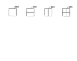
- FIG. 7A shows the size of a motion compensation pixel block in units of macroblocks
- FIG. 7B shows the size of a motion compensation pixel block in units of sub-blocks (8 ⁇ 8 pixel blocks or less).
- FIG. 7A shows a 16 ⁇ 16 pixel MB1, an MB2 composed of two 16 ⁇ 8 pixel blocks, an MB3 composed of two 8 ⁇ 16 pixel blocks, and an MB4 composed of four 8 ⁇ 8 pixel blocks. It is.
- FIG. 7B an SB of 8 ⁇ 8 pixels, an SB2 composed of two 8 ⁇ 4 pixel blocks, an SB3 composed of two 4 ⁇ 8 pixel blocks, and an SB4 composed of four 4 ⁇ 4 pixel blocks. Is shown.
- the optimal shape and motion vector of the prediction target block can be used according to the local nature of the input image signal 114.
- information on which reference image signal the motion vector is calculated can be changed as a minimum for each 8 ⁇ 8 pixel block as Ref_idx.
- the prediction image signal 123 generated by the motion compensation prediction unit 107 is input to the prediction separation switch 110, and depends on the connection destination of the output end of the switch controlled according to the prediction switching information 122 output from the prediction switching unit 111 described later. Selected.
- the motion vector 119 output from the motion estimation unit 106 is input to the geometric transformation parameter derivation unit 108, and the geometric transformation parameter 121 is generated.
- the geometric transformation parameter 121 is a parameter set for performing geometric transformation on the reference image signal 120.
- the geometric transformation parameter 121 output from the geometric transformation parameter derivation unit 108 is input to the geometric transformation prediction unit 109 and to the determination parameter derivation unit 127.
- the geometric transformation prediction unit 109 generates a predicted image signal 123 that has been subjected to geometric transformation using the input geometric transformation parameter 121 and the reference image signal 120.
- the geometric transformation parameter 121 of the prediction target block is held in the internal memory of the encoding control unit 126, and is used when the prediction target block becomes an adjacent block of another pixel block.
- the determination parameter deriving unit 127 determines whether to use the predicted image signal generated by the motion compensation prediction unit 107 or the predicted image signal generated by the geometric conversion prediction unit 109 based on the input geometric conversion parameter 121. A determination parameter for determining is derived. The determination parameter 125 generated by the determination parameter deriving unit 127 is input to the prediction switching unit 111.
- the prediction switching unit 111 outputs the prediction switching information 122 of the prediction target block according to the input determination parameter 125.
- the prediction separation switch 110 determines whether to connect the output terminal of the switch to the motion compensation prediction unit 107 or the geometric transformation prediction unit 109 according to the input prediction switching information 122. In accordance with this determination, one of the predicted image signals 123 is output to the subtracter 101 and the adder 104.
- the above is the flow of the encoding process of the moving image encoding apparatus 100.
- the geometric transformation parameter derivation unit 108 derives the geometric transformation parameter of the prediction target block using the motion vector 119 of the prediction target block output from the motion estimation unit 106 and the motion vector stored in the encoding control unit 126.
- the motion vector stored in the encoding control unit 126 is a motion vector of an adjacent block, and is hereinafter referred to as “adjacent motion vector”.
- FIG. 8 is a block diagram showing the configuration of the geometric transformation parameter deriving unit 108.
- the geometric transformation parameter derivation unit 108 includes a motion vector acquisition unit 181 and a parameter derivation unit 182.
- the motion vector acquisition unit 181 determines an adjacent block from which motion information is acquired from among a plurality of adjacent blocks, and acquires motion information of the adjacent block, for example, a motion vector.
- the parameter deriving unit 182 derives a geometric transformation parameter from the motion vector of the adjacent block.
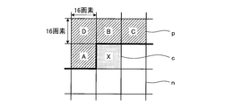
- FIG. 9A to 9E are diagrams illustrating the relationship between adjacent blocks with respect to a prediction target block.
- FIG. 9A shows an example in which the sizes of prediction target blocks and adjacent blocks (for example, 16 ⁇ 16 pixel blocks) match.
- a pixel block p with hatched hatching is a pixel block that has already been encoded or predicted (hereinafter referred to as “predicted pixel block”).
- a block c with dot hatching indicates a prediction target block, and a pixel block n displayed in white is an uncoded pixel (unpredicted) block.
- X represents an encoding (prediction) target pixel block.
- the adjacent block A is the adjacent block on the left of the prediction target block X
- the adjacent block B is the adjacent block on the prediction target block X
- the adjacent block C is the adjacent block on the upper right of the prediction target block X
- the adjacent block D is This is an adjacent block at the upper left of the prediction target block X.
- the adjacent motion vector held in the internal memory of the encoding control unit 126 is only the motion vector of the predicted pixel block. As shown in FIG. 4, since the pixel block is encoded and predicted from the upper left to the lower right, when the pixel block X is predicted, the right and lower pixel blocks are still encoded. Has not been made. Therefore, an adjacent motion vector cannot be derived from these adjacent blocks.
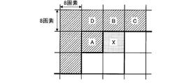
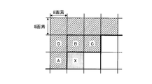
- FIG. 9B to 9E are diagrams illustrating examples of adjacent blocks when the prediction target block is an 8 ⁇ 8 pixel block.
- a bold line represents a macroblock boundary.
- 9B is a pixel block located at the upper left in the macro block
- FIG. 9C is a pixel block located at the upper right in the macro block
- FIG. 9D is a pixel block located at the lower left in the macro block
- FIG. 9E is a macro block.
- An example in which each pixel block located at the lower right in the block is a prediction target block is shown.
- the position of the adjacent block changes according to the encoding order of the 8 ⁇ 8 pixel block.
- the pixel block becomes an encoded pixel block and is used as an adjacent block of the pixel block to be processed later.
- the pixel block located at the upper right of the encoded pixel block is set as an adjacent block.
- FIG. 10A to FIG. 10D are diagrams illustrating an example in which the prediction target block is large and the adjacent block is small.
- FIG. 10A is an example in which a pixel block having a pixel closest to the upper left pixel of the prediction target block is set as an adjacent pixel.
- FIG. 10B is an example in which the pixel block located at the lower right of the pixel block adjacent to the prediction target block is set as the adjacent block.
- FIG. 10C is an example in which the pixel block existing at the center of the pixel block adjacent to the prediction target block is set as the adjacent block.
- the center of the pixel block adjacent to the left of the prediction target block X is an 8 ⁇ 8 pixel block boundary.
- the left pixel block is set as an adjacent block.
- FIG. 10D is an example in which the pixel block existing at the center of the pixel block adjacent to the prediction target block is an adjacent block. However, since the center point is located at the pixel block boundary as in FIG. 10C, This is an example in which a positioned pixel block is an adjacent block. When the center exists at the block boundary, any adjacent block may be defined as the central block, but the same definition is applied to all adjacent pixels. Thereby, when estimating the motion information of a prediction object block from the motion information of each adjacent block, the positional relationship with respect to an adjacent block can be expressed by the same phase.
- FIG. 11A to FIG. 11D are diagrams for explaining an example when the prediction target block is small and the block size of the adjacent block is large.
- FIG. 9E when the corresponding pixel block is an uncoded pixel block, it is replaced with a coded pixel block that can be used that is close in distance to the prediction target block.
- FIG. Adjacent blocks may be determined using any of 10D. Even when pixel blocks having different block sizes are mixed, adjacent blocks may be determined using any one of FIGS. 10A to 10D.
- adjacent blocks may be defined more widely.
- a pixel block on the left of the adjacent block A may be used, or a pixel block further on the adjacent block B may be used.
- the definition of these adjacent blocks may be defined similarly to the definitions of FIGS. 9 to 11 described above.
- the motion vector 119 provided from the motion estimation unit 106 is defined by equation (8).
- the motion vector 119 is a motion vector of the prediction target block X.
- the geometric transformation parameter 121 is derived using the motion vector and the adjacent motion vector represented by the equations (4) to (8).
- the transformation formula is expressed by the following formula (9).
- equation (9) coordinates (x, y) are converted to coordinates (u, v) by affine transformation.
- Six parameters a, b, c, d, e, and f included in Expression (9) represent geometric transformation parameters.
- affine transformation since these six types of parameters are estimated, six or more input values are required.
- geometric transformation parameters are derived by the following equation (10). Here, it is assumed that the motion vector is 1 ⁇ 4 precision.
- ax and ay are variables based on the size of the prediction target block, and are calculated by the following equations.
- mb_size_x and mb_size_y indicate the horizontal and vertical sizes of the macroblock.
- blk_size_x and blk_size_y represent the horizontal and vertical sizes of the prediction target block.
- FIG. 12 is a diagram illustrating an example in which a median value is calculated for each of four 8 ⁇ 8 pixel blocks.
- the motion vectors of the four pixel blocks located on the left are mv a , mv b , mv c , and mv d , the motion vector is determined by the following equation (12).
- an average value for each element, a random value of a two-dimensional vector, a random value for each element of the vector, or the like may be used.
- the adjacent motion vectors may be obtained by performing the same processing in the adjacent blocks B, C, and D.
- Equation (10) shows an example in which a geometric transformation parameter is derived for a rectangular pixel block.
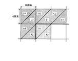
- the rectangular block may be divided by the triangular patch shown in FIG. 13A and 13B show an example in which the prediction target block is divided by a diagonal line and divided by two triangular patches.
- each geometric transformation parameter is derived by the following equation.
- the prediction target triangular patch X1 is defined by the following equation (14) using the motion vectors of the adjacent blocks A and D and the prediction target block X1.
- the prediction target triangular patch X2 is defined by the following equation (15) using the motion vectors of the adjacent blocks B and D and the prediction target block X2.
- the geometric transformation parameter is derived using the motion vector of the adjacent block having a spatial distance close to the prediction target triangular patch (or the prediction target block).
- the geometric transformation parameters can be derived in the same manner.
- the prediction target triangular patch X2 has a spatial distance close to the uncoded pixel block side and a spatial distance from an adjacent block.
- the division shape may be further divided by a plurality of triangular patches, and a rectangle, a curve, a trapezoid, and a parallelogram. You may divide
- an example using affine transformation is shown as an example of geometric transformation, but any geometric transformation such as bilinear transformation, Helmart transformation, quadratic conformal transformation, projective transformation, three-dimensional projective transformation, etc. is used. May be.
- the projective transformation is expressed by the following equation (16).
- equation (16) if the numerator denominator is divided into scalars, there are eight parameters to be solved. Thus, by defining a large number of adjacent blocks that can be used, it is possible to derive geometric transformation parameters in the same framework as affine transformation. The above is the outline of the processing of the geometric transformation parameter derivation unit 108.
- the geometric transformation prediction unit 109 performs geometric transformation on the reference image signal 120 based on the inputted geometric transformation parameter 121 to perform geometric transformation prediction.
- FIG. 14 is a block diagram illustrating an example of the configuration of the geometric transformation prediction unit 109.
- the geometric transformation prediction unit 109 includes a geometric transformation unit 191 and an interpolation unit 192.
- the geometric conversion unit 191 performs geometric conversion on the reference image signal 120 and calculates the position of the predicted pixel.
- the interpolation unit 192 calculates the predicted pixel value corresponding to the fractional position of the predicted pixel obtained by the geometric transformation by interpolation or the like.
- FIG. 15 is a diagram illustrating an example of geometric transformation prediction and motion compensation prediction for a prediction target block.
- FIG. 15 is an example of a 16 ⁇ 16 pixel block.
- the prediction target block is a square pixel block CR composed of pixels indicated by triangles.
- the corresponding pixels of motion compensated prediction are indicated by black circles.
- a pixel block MER composed of pixels indicated by black circles is a square.
- pixels corresponding to the geometric transformation prediction are indicated by x, and a pixel block GTR composed of these pixels is a parallelogram.
- the region after motion compensation and the region after geometric transformation describe the corresponding region of the reference image signal according to the coordinates of the frame to be encoded.
- the geometric transformation prediction it is possible to generate a predicted image signal in accordance with deformation such as rotation, enlargement / reduction, shearing, and mirror transformation of the rectangular pixel block.
- the geometric transformation unit 191 uses the geometric transformation parameter 121 calculated using the equations (10), (14), and (15), and uses the geometric transformation parameters (u, v) according to the equation (9). ) Is calculated.
- the calculated coordinates (u, v) after geometric transformation are real values. Therefore, the predicted value is generated by interpolating the luminance value corresponding to the coordinates (u, v) from the reference image signal.
- Equation (10), Equation (14), and Equation (15) since the fractional position can be calculated without error by 6-bit calculation, the pixel accuracy at the time of interpolation is 6 bits. Thus, the integer pixels are divided into 64 fractional pixels.
- FIG. 16 is a diagram illustrating an example of luminance value interpolation processing by bilinear interpolation.
- White circles cw0 to cw3 indicate luminance values at integer pixel positions, and black circles cb indicate interpolation pixel positions (u, v).
- the interpolated pixel value is generated from the ratio of the distances using the surrounding four integer pixel values adjacent to the fractional accuracy position.
- the bilinear interpolation method is expressed by the following equation (17).
- a new predicted image signal is generated by applying interpolation for each coordinate in the prediction target block subjected to geometric transformation.
- bilinear interpolation is used as an interpolation method.
- nearest neighbor interpolation cubic convolution interpolation
- linear filter interpolation linear filter interpolation
- Lagrange interpolation Lagrange interpolation
- spline spline
- Any interpolation method such as an interpolation method or a Lanczos interpolation method may be applied.
- the example of the interpolation from the integer pixel position of the reference image signal has been described.
- the interpolated image signal with fractional precision may be reused.
- the motion estimation unit 106 calculates a motion vector with 1 ⁇ 4 pixel accuracy, if an enlarged reference image signal obtained by enlarging the reference image signal by four times is generated and held, the 1 ⁇ 4 pixel
- An interpolation image with 1/64 pixel accuracy may be generated using an accuracy interpolation image.
- an interpolation image with 1/64 pixel accuracy can be generated by further performing interpolation interpolation processing with 1/16 accuracy from the 1/4 accuracy interpolation image.
- the pixel accuracy of the interpolation process can be specified more finely.
- an interpolation process may be performed according to the designated interpolation accuracy. The above is the outline of the processing of the geometric transformation prediction unit 109.
- the determination parameter deriving unit 127 uses the geometric transformation parameter 121 output from the geometric transformation parameter deriving unit 108 and the predicted image signal output from the motion compensation prediction unit 107 and the predicted image signal output from the geometric transformation prediction unit 109.
- the geometric transformation is an affine transformation
- the degree of geometric transformation can be evaluated using a parallel movement index, a rotation index, an enlargement / reduction index, a deformation index, and the like.
- the correlation in the time direction is high. Since the motion vector is a value indicating the movement of an object between temporally different images, it is expected that the spatial correlation of motion is relatively high. Therefore, the prediction method is dynamically switched using these indexes as determination parameters.
- the parallel movement index is given by the following equation (19).
- Equation (19) cn represents the c component of the geometric transformation parameter of the adjacent block or the adjacent triangular patch obtained by dividing the prediction target block, that is, the triangular patch in the adjacent block of the same number in FIG. , Cx indicate the c component of the geometric transformation parameter of the adjacent block.
- the adjacent relationship with the divided triangular patches of the same shape is referred to. The same applies to the f component.
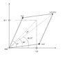
- FIG. 17 is a diagram illustrating an example of changes in pixel blocks due to affine transformation.
- coordinates (1, 0) and (0, 1) are converted into coordinates (a, d) and (b, c) by affine transformation, respectively, and rotated by ⁇ D from the center angle 45 ° of the vector before conversion.
- Each of a, b, d, and e indicates a geometric transformation parameter obtained in the prediction target block.
- the rotation index is given by the following equation (20).
- sgn (A) is a function that returns the sign of A. This shows how much the center vector of the rectangular block has been rotated.
- an enlargement / reduction index corresponds to the area after the affine transformation shown in FIG. Therefore, an enlargement / reduction index is defined by the following equation.
- the rotation index may be calculated using the following equation.
- the difference value between each component of the geometric transformation parameter calculated in the adjacent block and each component of the geometric transformation parameter calculated in the prediction target block shown in Expression (24) is also set as one parameter of the determination parameter.
- the following determination parameters may be used by using the prediction target block and the adjacent block index calculated using Expression (20), Expression (21), Expression (22), and Expression (23). .
- Detn is calculated from the geometric transformation parameter held by the adjacent block or the triangular patch of the adjacent block.
- a difference value between the index corresponding to the calculated geometric transformation parameter and the geometric transformation parameter is output to the prediction switching unit 111 as the determination parameter 125.
- the above is the outline of the processing of the determination parameter deriving unit 127.
- the prediction switching unit 111 generates prediction switching information 122 that describes which prediction image signal is used based on the determination parameter 125 output from the determination parameter deriving unit 127.
- the rotation index, the enlargement / reduction index, and the deformation index are indices that aim at the degree of rotation, enlargement, reduction, and deformation of the pixel block in addition to the parallel movement of only the motion vector.
- the calculated geometric transformation parameter index is extremely large or small, it is expected that the estimation of the geometric transformation parameter is inappropriate, and a predicted image generated by geometric transformation prediction using this parameter The signal is expected to contain many errors. Therefore, when these indices exceed a predetermined threshold range, the prediction switching information 122 is generated so as not to use the prediction image signal of the geometric transformation prediction.
- the threshold range in the enlargement / reduction index of Expression (21) will be described.
- Det is an index indicating the degree of enlargement / reduction.
- the prediction switching information 122 is defined by the following formula (28).
- pred_flag represents the prediction switching information 122
- ThDet represents a threshold value.
- pred_flag is 0, and motion compensation prediction is selected.
- pred_flag is 1, and geometric transformation prediction is selected. Similar threshold determination is performed for other determination parameters, and prediction switching information 122 is generated.
- the quantization parameter included in the encoding parameter is a parameter that defines the quantization step size.
- the quantization parameter is large, the transform coefficient is roughly quantized.
- the locally decoded reference image signal has a large error with respect to the input image signal, and the motion vector estimation accuracy decreases.
- geometric transformation prediction since a geometric transformation parameter is calculated using a motion vector, if the estimation accuracy of the motion vector is lowered, the calculation accuracy of the geometric transformation parameter is also lowered. Therefore, when the quantization parameter becomes large, processing for narrowing the threshold range of various determination parameters is performed. That is, the threshold value of each parameter is a decreasing function for the quantization parameter.
- the example in which the threshold range is controlled using the quantization parameter is shown, but other information included in the encoding parameter may be used.
- information regarding the resolution of the encoded moving image, the type of the prediction target block, the Ref_idx of the reference image, the value of the motion vector, or the transform size may be used.
- the prediction switching information 122 has a value indicating that the geometric transformation prediction is not used.
- the threshold value used for each index may be a function that changes according to the value of the encoding parameter.
- the threshold ThDet in Equation (28) is defined as a function that depends on the quantization parameter, and the function is such that the threshold decreases as the quantization parameter increases, thereby reducing the estimation accuracy. It is possible to effectively switch predictions. The above is the outline of the processing of the prediction switching unit 111 and the prediction separation switch 110.
- FIG. 18 is a flowchart showing the process of generating a predicted image signal by the inter prediction unit 130.
- the processing is started (S501)
- the motion vector 119 of the prediction target block input from the outside of the inter prediction unit 130 is input to the geometric transformation parameter deriving unit 108.
- the geometric transformation parameter derivation unit 108 determines an adjacent block corresponding to the prediction target block (S502).
- the adjacent motion vector of the corresponding adjacent block is derived from the internal memory S511 held by the encoding control unit 126 (S503).
- the geometric transformation parameter deriving unit 108 derives the geometric transformation parameter 121 using the derived adjacent motion vector and the motion vector of the prediction target block (S504).
- the geometric transformation process of the prediction target block is performed in the geometric transformation prediction unit 109 using the derived geometric transformation parameter 121 (S505).
- the geometric transformation prediction unit 109 generates a prediction image signal at a fractional pixel position newly calculated by geometric transformation by interpolation (S506).
- the geometric transformation parameter 121 calculated by the geometric transformation parameter deriving unit 108 and stored in the internal memory S511 is input to the determination parameter deriving unit 127, and the determination parameter 125 is calculated (S507).
- the calculated determination parameter 125 is input to the prediction switching unit 111, and the prediction switching information 122 is generated (S508).
- the geometric transformation parameter 121 calculated in the prediction target block is stored as S511 in the internal memory possessed in the encoding control unit 126 (S509).
- the motion vector 119 is stored in the internal memory S511 possessed in the encoding control unit 126 (S510).
- the prediction separation switch 110 determines whether or not the prediction method of the prediction target block uses the predicted image signal generated by the geometric transformation prediction unit 109 (S512). When this determination is YES, the prediction separation switch 110 connects the output end of the geometric transformation prediction unit 109 to the switch, and outputs a predicted image signal (S513).
- the motion compensation prediction unit 107 performs motion compensation prediction processing according to the motion vector 119 (S514).
- the prediction separation switch 110 connects the switch to the output terminal of the motion compensation prediction unit 107 and outputs a prediction image signal (S515).
- the encoding control unit 126 determines whether or not the prediction target block is the last block in the macroblock (S516). If this determination is YES, the prediction process for the macroblock is ended (S517). ). If this determination is NO, the process returns to the beginning, and a predicted image generation process for the pixel block next to the macroblock is performed.
- the above is the flow of the prediction image generation processing of inter prediction in the present embodiment of the present invention.
- FIG. 19 is a diagram illustrating a configuration of the syntax 1600.
- the syntax 1600 mainly has three parts.
- the high-level syntax 1601 has higher layer syntax information that is equal to or higher than a slice.
- the slice level syntax 1602 has information necessary for decoding for each slice, and the macroblock level syntax 1603 has information necessary for decoding for each macroblock.
- High level syntax 1601 includes sequence and picture level syntax, such as sequence parameter set syntax 1604 and picture parameter set syntax 1605.
- the slice level syntax 1602 includes a slice header syntax 1606, a slice data syntax 1607, and the like.
- the macroblock level syntax 1603 includes a macroblock layer syntax 1608, a macroblock prediction syntax 1609, and the like.
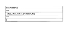
- FIG. 20 is a diagram illustrating an example of the slice header syntax 1606.
- the slice_affine_motion_prediction_flag shown in the figure is a syntax element indicating whether or not geometric transformation prediction is applied to the slice.
- slice_affine_motion_prediction_flag is 0, the prediction switching unit 111 sets the prediction switching information 122 so as to always output the output terminal of the motion compensation prediction unit 107 in the slice, and switches the prediction separation switch 110. That is, this means that geometric transformation prediction is not applied to this slice.
- slice_affine_motion_prediction_flag is 1, the prediction switching information 122 is set based on information indicated by the determination parameter 125 in the slice, and the prediction separation switch 110 dynamically switches the prediction image signal.
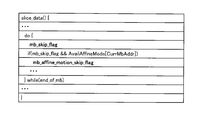
- FIG. 21 is a diagram illustrating an example of the slice data syntax 1607.
- Mb_skip_flag shown in the drawing is a flag indicating whether or not the macroblock is encoded in the skip mode. In the skip mode, transform coefficients, motion vectors, etc. are not encoded.
- AvailAffineMode is an internal parameter indicating whether or not geometric transformation prediction can be used in the macroblock. When AvailAffineMode is 0, it means that the prediction switching information 122 is set not to use the geometric transformation prediction by various values calculated by the determination parameter 125. Also, AvailAffineMode is 0 when the adjacent motion vector of the adjacent block and the motion vector of the prediction target block have the same value.
- mb_affine_motion_skip_flag indicating whether to use geometric transformation prediction or motion compensation prediction is encoded.
- mb_affine_motion_skip_flag 1, it means that geometric transformation prediction is applied to the skip mode.
- mb_affine_motion_skip_flag 0, it means that motion compensation prediction is applied.
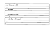
- FIG. 22 is a diagram illustrating an example of the macroblock layer syntax 1608.
- Mb_type shown in the figure indicates macroblock type information. That is, whether the current macroblock is intra-coded, inter-coded, what block shape is being predicted, whether the prediction direction is unidirectional prediction or bidirectional prediction, etc. Contains information.
- the mb_type is passed to the macroblock prediction syntax and the submacroblock prediction syntax indicating the syntax of the subblock in the macroblock.
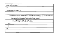
- FIG. 23 is a diagram illustrating an example of the macroblock prediction syntax.
- AvailAffineModeMb shown in the figure is an internal parameter indicating whether or not geometric transformation prediction can be used in the pixel block. When AvailAffineModeMb is 0, it means that the prediction switching information 122 is set not to use the geometric transformation prediction by various values calculated by the determination parameter 125. Also, AvailAffineModeMb is 0 when the adjacent motion vector of the adjacent block and the motion vector of the prediction target block have the same value.
- mb_affine_pred_flag indicating whether to use geometric transformation prediction or motion compensation prediction is encoded.
- mb_affine_pred_flag 1, it means that geometric transformation prediction is applied to the pixel block.
- mb_affine_pred_flag 0, it means that motion compensation prediction is applied.
- NumMbPart () is an internal function that returns the number of block divisions specified in mb_type. It is 1 for a 16 ⁇ 16 pixel block, 2 for an 8 ⁇ 16 pixel block, and 2 for an 8 ⁇ 8 pixel block. In the case, 4 is output.
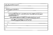
- FIG. 24 is a diagram illustrating an example of sub-macroblock prediction syntax.
- AvailAffineModeSubMb shown in the figure is an internal parameter indicating whether or not geometric transformation prediction can be used in the pixel block. When AvailAffineModeSubMb is 0, it means that the prediction switching information 122 is set not to use the geometric transformation prediction by various values calculated by the determination parameter 125.
- the AvailAffineModeSubMb is also 0 when the adjacent motion vector of the adjacent block and the motion vector of the prediction target block have the same value.
- mb_affine_pred_flag indicating which of geometric transformation prediction and motion compensation prediction is used is encoded.
- mb_affine_pred_flag 1, it means that geometric transformation prediction is applied to the pixel block.
- mb_affine_pred_flag 0, it means that motion compensation prediction is applied.
- NumSubMbPart () is an internal function that returns the number of block divisions defined in mb_type.
- FIG. 25 is a diagram illustrating an example of macroblock layer syntax as an example of an encoding parameter.
- Coded_block_pattern shown in the figure indicates whether a transform coefficient exists for each 8 ⁇ 8 pixel block. For example, when this value is 0, it means that there is no transform coefficient in the target block.
- Mb_qp_delta in the figure indicates information related to the quantization parameter. The difference value from the quantization parameter of the block encoded immediately before the target block is represented.
- Ref_idx_l0 and ref_idx_l1 in the figure indicate reference image indexes indicating which reference image is used to predict the target block when inter prediction is selected.
- Mv_l0 and mv_l1 in the figure indicate motion vector information.
- transform — 8 ⁇ 8_flag represents conversion information indicating whether or not the target block is 8 ⁇ 8 conversion.
- syntax elements not defined in the present embodiment may be inserted between lines in the syntax tables shown in FIGS. 19 to 25, and descriptions regarding other conditional branches may be included.
- the syntax table may be divided into a plurality of tables, or a plurality of syntax tables may be integrated. Moreover, it is not always necessary to use the same term, and it may be arbitrarily changed depending on the form to be used. Further, each syntax element described in the macroblock layer syntax may be changed as specified in a macroblock data syntax described later. The above is the description of the video encoding device 100 according to the first embodiment.
- FIG. 26 shows the structure of the moving picture coding apparatus 200 used in the second embodiment.
- symbol is attached
- an intra prediction unit 201, a mode determination unit 202, and a prediction mode separation switch 203 are newly added.
- the intra prediction unit 201 generates a predicted image signal 123 using only the information in the screen based on the input reference image signal 120.
- H.264 H.264 intra prediction will be described.
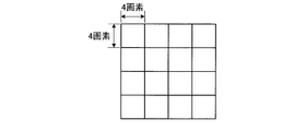
- H. Pixel blocks used for H.264 intra prediction are shown in FIGS. 27A to 27C.
- FIG. 27A is a 16 ⁇ 16 pixel intra prediction
- FIG. 27B is a 4 ⁇ 4 pixel intra prediction
- FIG. 27C is a pixel block used for 8 ⁇ 8 pixel intra prediction.
- H. H.264 defines these three intra predictions.
- intra prediction an interpolated pixel is created from a reference image signal 120 stored in the reference image memory 105, and a predicted value is generated by copying in the spatial direction.
- the mode determination unit 202 outputs the prediction mode switching information 204 to the prediction mode separation switch 203 according to the information of the slice that is currently encoded.
- the prediction mode switching information 204 describes information about which of the output terminal of the intra prediction unit 201 and the output terminal of the inter prediction unit 130 is connected to the switch.
- the mode determination unit 202 connects the output terminal of the prediction mode separation switch 203 to the intra prediction unit 201.
- the mode determination unit 202 determines whether the prediction mode separation switch 203 is connected to the output end of the intra prediction unit 201 or the output end of the inter prediction unit 130. judge.
- the mode determination unit 202 performs mode determination using the cost of the following equation (29), for example.
- the code amount related to the prediction information required when each prediction mode is selected for example, the code amount of the motion vector 119 or the code amount of the block shape is OH, the absolute difference sum of the input image signal 114 and the predicted image signal 123,
- the absolute cumulative sum of the prediction error signal 115 is SAD, the following mode determination formula (29) is used.
- K is the cost and ⁇ is a constant.
- ⁇ is a Lagrangian undetermined multiplier determined based on the quantization scale and the value of the quantization parameter.
- Mode determination is performed based on the cost K obtained by the equation (29). That is, the mode that gives the smallest value of cost K is selected as the optimal prediction mode.
- the mode determination unit 202 may perform mode determination using (a) only the prediction information and (b) only SAD instead of the equation (29), and the Hadamard may be included in these (a) and (b). You may use the value which performed conversion, or the value approximated to it. Further, the mode determination unit 202 may create the cost by using the activity of the input image signal 114, that is, the variance of the signal value, or by creating a cost function using the quantization scale or the quantization parameter. Also good.
- a provisional encoding unit is prepared, and the amount of codes when the prediction error signal 115 actually generated by the provisional encoding unit in a certain prediction mode is encoded, the input image signal 114 and the decoded image signal.
- the mode determination may be performed using a square error with respect to 118.
- the mode judgment formula in this case is the following formula (30).
- Equation (30) J is the encoding cost, and D is the encoding distortion representing the square error between the input image signal 114 and the decoded image signal 118.
- R represents a code amount estimated by provisional encoding.
- the cost J of Equation (30) When the encoding cost J of Equation (30) is used, provisional encoding and local decoding processing are required for each prediction mode, so that the circuit scale or the amount of calculation increases. On the other hand, since a more accurate code amount and encoding distortion are used, high encoding efficiency can be maintained.
- the cost may be calculated using only R or only D instead of Expression (30), and the cost function may be created using a value approximating R or D.
- the prediction image signal 123 of the prediction mode selected here is output and input to the subtracter 101 and output to the adder 104.
- FIG. 28 shows the structure of the inter prediction unit 300 used in the third embodiment.
- symbol is attached
- the inter prediction unit 300 can be replaced with the inter prediction unit 130 included in the video encoding device 100 and the video encoding device 200.
- a motion vector re-search unit 301 is newly added.
- the motion vector re-search unit 301 further re-searches the motion vectors in the peripheral part with the input motion vector 119 as a reference.
- the motion vector 119 of the prediction target block inputted from the outside and the neighboring pixel vector held in the encoding control unit 126 are inputted to the geometric transformation parameter deriving unit 108, and the geometric transformation parameter 121 is calculated.
- the geometric transformation parameter 121 is input to the geometric transformation prediction unit 109 to perform geometric transformation prediction, and a predicted image signal is generated.
- the motion vector re-search unit 301 changes the motion vector of the prediction target block within the search range given from the encoding control unit 126 with the input motion vector 119 as a reference, and re-derived geometric transformation parameters.
- the re-derived geometric transformation parameters are input to the geometric transformation prediction unit 109, re-geometric transformation prediction is performed, and a predicted image signal is generated. In this way, using the motion vector of the prediction target block generated by the motion vector re-search unit 301, geometric conversion prediction for the re-search range is performed.
- the cost is calculated using the formula (29) or the formula (30), and only the motion vector and the predicted image signal with the low cost are left.
- a motion vector and a predicted image signal that give the minimum cost are output to the prediction separation switch 110. Coding efficiency can be improved by changing the motion vector of the prediction target block so that the prediction error becomes small.
- the configuration of the video encoding apparatus according to the fourth embodiment is the same as that of the third embodiment.
- the video encoding device according to the fourth embodiment encodes the difference between the motion vector of the prediction target block and the motion vector calculated by the re-search in addition to the operation of the video encoding device according to the third embodiment.
- the original motion vector is changed to reduce the prediction error. If the motion vector after this re-search is used as an adjacent motion vector, the subsequent geometric transformation parameter may not be derived properly.
- L0 and l0 indicate motion vectors indicated on the reference image L0
- L1 and l1 indicate motion vectors indicated on the reference image L1.
- mvd_affine [0] is a motion vector difference value corresponding to the vertical direction and mvd_affine [1] is corresponding to a syntax element.
- the characters l0 and l1 included in the syntaxes shown in FIGS. 29 and 30 are omitted, but the motion vector difference shown in the equation (31) is different from the indexes L0 and L1.
- mvd_l0 and mvd_l1 are calculated by calculating a difference between a motion vector corresponding to each reference image signal and a value predicted from the motion vector, and use other motion vector prediction techniques not explicitly shown in the present embodiment. Generated.
- mv org (mvx org , mvy org ), which is a motion vector before re-searching, is stored in the internal memory of the encoding control unit 126. In this way, by separately holding the motion vector used in the prediction target block and the motion vector used when it becomes an adjacent block, it is possible to prevent propagation of errors in geometric transformation parameters from the adjacent block Become.
- FIG. 31 shows a video decoding device according to the fourth embodiment.
- the moving picture decoding apparatus 400 in FIG. 31 decodes encoded data generated by the moving picture encoding apparatus according to the first embodiment.
- the encoded data 411 is encoded data that is transmitted from, for example, the moving image encoding apparatus 100, transmitted through a storage system or a transmission system, once stored in the input buffer 401, and multiplexed.
- the moving picture decoding apparatus 400 includes an encoded data decoding unit 402, an inverse quantization / inverse transform unit 403, an adder 404, a reference image memory 405, a motion compensation prediction unit 406, a geometric transformation parameter derivation unit 407, and a geometric transformation prediction unit. 408, a determination parameter deriving unit 422, a prediction switching unit 409, and a prediction separation switch 410.
- the video decoding device 400 is also connected to the input buffer 401, the output buffer 419, and the decoding control unit 421.
- the encoded data decoding unit 402 decodes the encoded data by syntax analysis based on the syntax for each frame or field.
- the encoded data decoding unit 402 sequentially entropy-decodes the code string of each syntax, and reproduces the motion vector 415, the encoding parameter of the target block, and the like.
- the encoding parameter is a parameter required for decoding prediction information, information on transform coefficients, information on quantization, and the like.
- the transform coefficient decoded by the encoded data decoding unit 402 is input to the inverse quantization / inverse transform unit 403.
- Various information relating to the quantization decoded by the encoded data decoding unit 402, that is, the quantization parameter and the quantization matrix are set in the internal memory of the decoding control unit 421 and used as an inverse quantization process. Loaded.
- the inverse quantization / inverse transform unit 403 first performs inverse quantization processing using the loaded information relating to quantization. Subsequently, the inverse quantized transform coefficient is subjected to inverse transform processing, for example, inverse discrete cosine transform. Here, the inverse orthogonal transform has been described. However, when wavelet transform or the like is performed in the encoding device, the inverse quantization / inverse transform unit 403 executes the corresponding inverse quantization and inverse wavelet transform. Good.
- the restored prediction error signal 412 is input to the adder 404.
- the adder 404 adds a prediction error signal 412 and a predicted image signal 418 generated by a motion compensation prediction unit 406 or a geometric transformation prediction unit 408 described later to generate a decoded image signal 420.
- the generated decoded image signal 420 is output from the video decoding device 400, temporarily stored in the output buffer 419, and then output according to the output timing managed by the decoding control unit 421.
- the decoded image signal 420 is stored in the reference image memory 405 and becomes a reference image signal 413.
- the reference image signal 413 is sequentially read from the reference image memory 405 for each frame or field, and is input to the prediction motion compensation prediction unit 406 or the geometric transformation prediction unit 408.
- the motion vector 415 and the geometric transformation parameter 414 used in the target pixel block are stored in the decoding control unit 421 and are appropriately loaded and used by the geometric transformation parameter deriving unit 108 and the determination parameter deriving unit 422 described later.
- the motion compensation prediction unit 406, the geometric transformation parameter derivation unit 407, the geometric transformation prediction unit 408, the determination parameter derivation unit 422, the prediction switching unit 409, and the prediction separation switch 410 in FIG. 31 have the same names shown in FIG. It has the same function and configuration as each part. More specifically, the motion vector input to the motion compensation prediction unit 107 is acquired by the motion estimation unit 106, whereas the motion vector input to the motion compensation prediction unit 406 is encoded data decoding. All are the same except that they are decrypted by the unit 402.
- FIG. 32 includes the motion compensation prediction unit 406, the geometric transformation parameter derivation unit 407, the geometric transformation prediction unit 408, the determination parameter derivation unit 422, the prediction switching unit 409, and the prediction separation switch 410 in FIG. FIG.
- Each of these units has the same function and configuration as each unit of the inter prediction unit 130 shown in FIG. Therefore, when the moving picture decoding apparatus 400 holds the inter prediction unit 130 included in the moving picture encoding apparatus 100, the configuration illustrated in FIG. 31 can be realized.
- ⁇ Geometric transformation parameter derivation unit 407 In the geometric transformation parameter deriving unit 407, the motion vector 415 of the prediction target block decoded by the encoded data decoding unit 402 and the motion vector stored in the decoding control unit 421 (hereinafter referred to as “adjacent motion vector”). The geometric transformation parameter of the prediction target block is derived by using this.
- blocks to be encoded or predicted “pixel blocks for which encoding or prediction has been completed” and “uncoded”.
- unpredicted pixel block in the fifth to seventh embodiments, “decoding or prediction target block”, “decoded or predicted pixel block” and “undecoded or unpredicted”, respectively. It is read as “pixel block”.
- FIG. 9A shows an example in which the sizes of prediction target blocks and adjacent blocks (for example, 16 ⁇ 16 pixel blocks) match.
- a pixel block p with hatched hatching is a pixel block that has already been decoded or predicted (hereinafter referred to as “predicted pixel block”), and has been hatched with dots.
- the block c is a prediction target block
- the pixel block n displayed in white is an undecoded pixel (unpredicted) block.
- X represents a decoding (prediction) target pixel block.
- the adjacent block A is the adjacent block on the left of the prediction target block X
- the adjacent block B is the adjacent block on the prediction target block X
- the adjacent block C is the adjacent block on the upper right of the prediction target block X
- the adjacent block D is This is an adjacent block at the upper left of the prediction target block X.
- the adjacent motion vector held in the internal memory of the decoding control unit 421 is only the motion vector of the predicted pixel block.
- a block located on the left and above the block c to be decoded is a decoded block p.
- the pixel block is decoded and predicted from the upper left to the lower right, when the pixel block X is predicted, the right and lower pixel blocks are still decoded. Has not been made. Therefore, an adjacent motion vector cannot be derived from these adjacent blocks.
- FIG. 9B to 9E are diagrams illustrating examples of adjacent blocks when the prediction target block is an 8 ⁇ 8 pixel block.
- a bold line represents a macroblock boundary.
- 9B is a pixel block located at the upper left in the macro block
- FIG. 9C is a pixel block located at the upper right in the macro block
- FIG. 9D is a pixel block located at the lower left in the macro block
- FIG. 9E is a macro block.
- An example in which each pixel block located at the lower right in the block is a prediction target block is shown.
- the decoding process is performed from the upper left to the lower right inside the macro block, so that the position of the adjacent block changes according to the decoding order of the 8 ⁇ 8 pixel block.
- the pixel block becomes a decoded pixel block and is used as an adjacent block of the pixel block to be processed later.
- the pixel block located at the upper right of the decoded pixel block is set as the adjacent block.
- FIG. 10A to FIG. 10D are diagrams illustrating an example in which the prediction target block is large and the adjacent block is small.
- FIG. 10A is an example in which a pixel block having a pixel closest to the upper left pixel of the prediction target block is set as an adjacent pixel.
- FIG. 10B is an example in which the pixel block located at the lower right of the pixel block adjacent to the prediction target block is set as the adjacent block.
- FIG. 10C is an example in which the pixel block existing at the center of the pixel block adjacent to the prediction target block is set as the adjacent block.
- the center of the pixel block adjacent to the left of the prediction target block X is an 8 ⁇ 8 pixel block boundary.
- the left pixel block is set as an adjacent block.
- FIG. 10D is an example in which the pixel block existing at the center of the pixel block adjacent to the prediction target block is an adjacent block. However, since the center point is located at the pixel block boundary as in FIG. 10C, This is an example in which a positioned pixel block is an adjacent block. When the center exists at the block boundary, any adjacent block may be defined as the central block, but the same definition is applied to all adjacent pixels. Thereby, when estimating the motion information of a prediction object block from the motion information of each adjacent block, the positional relationship with respect to an adjacent block can be expressed by the same phase.
- FIG. 11A to FIG. 11D are diagrams for explaining an example when the prediction target block is small and the block size of the adjacent block is large.
- FIG. 9E when the corresponding pixel block is an undecoded pixel block, it is replaced with an available decoded pixel block that is close in distance to the prediction target block.
- FIG. Adjacent blocks may be determined using any of 10D. Even when pixel blocks having different block sizes are mixed, adjacent blocks may be determined using any one of FIGS. 10A to 10D.
- adjacent blocks may be defined more widely.
- a pixel block on the left of the adjacent block A may be used, or a pixel block further on the adjacent block B may be used.
- the definition of these adjacent blocks may be defined similarly to the definitions of FIGS. 9 to 11 described above.
- the motion vector 119 provided from the motion estimation unit 106 is defined by equation (8).
- the motion vector 119 is a motion vector of the prediction target block X.
- the geometric transformation parameter 121 is derived using the motion vector and the adjacent motion vector represented by the equations (4) to (8).
- the geometric transformation is an affine transformation
- the transformation formula is expressed by Equation (9).
- coordinates (x, y) are converted to coordinates (u, v) by affine transformation.
- Six parameters a, b, c, d, e, and f included in Expression (9) represent geometric transformation parameters.
- these six types of parameters are estimated, six or more input values are required.
- a geometric transformation parameter is derived by Expression (10).
- the motion vector is 1 ⁇ 4 precision.
- ax and ay are variables based on the size of the prediction target block, and are calculated by Expression (11).
- FIG. 12 is a diagram illustrating an example in which a median value is calculated for each of four 8 ⁇ 8 pixel blocks.
- the motion vectors of the four pixel blocks located on the left are mv a , mv b , mv c , and mv d .
- a median value of a two-dimensional vector is shown, but as shown in Formula (13), a median value for each vector element may be used.
- an average value for each element, a random value of a two-dimensional vector, a random value for each element of the vector, or the like may be used.
- the adjacent motion vectors may be obtained by performing the same processing in the adjacent blocks B, C, and D.
- Equation (10) shows an example in which a geometric transformation parameter is derived for a rectangular pixel block.
- the rectangular block may be divided by the triangular patch shown in FIG. 13A and 13B show an example in which the prediction target block is divided by a diagonal line and divided by two triangular patches.
- each geometric transformation parameter is derived by the following equation.
- the prediction target triangular patch X1 is defined by Expression (14) using the motion vectors of the adjacent blocks A and D and the prediction target block X1.
- the prediction target triangular patch X2 is defined by Expression (15) using the motion vectors of the adjacent blocks B and D and the prediction target block X2.
- geometric transformation parameters are derived using motion vectors of adjacent blocks that are close in spatial distance to the prediction target triangular patch (or prediction target block).
- the geometric transformation parameters can be derived in the same manner.
- the prediction target triangular patch X2 has a spatial distance close to the undecoded pixel block side and a spatial distance from an adjacent block.
- the division shape may be further divided by a plurality of triangular patches, and a rectangle, a curve, a trapezoid, and a parallelogram. You may divide
- an example using affine transformation is shown as an example of geometric transformation, but any geometric transformation such as bilinear transformation, Helmart transformation, quadratic conformal transformation, projective transformation, three-dimensional projective transformation, etc. is used. May be.
- the projective transformation is expressed by Expression (16).
- equation (16) if the numerator denominator is divided into scalars, there are 8 parameters to be solved. Thus, by defining a large number of adjacent blocks that can be used, it is possible to derive geometric transformation parameters in the same framework as affine transformation.
- the geometric transformation prediction unit 408 performs geometric transformation on the reference image signal 413 based on the inputted geometric transformation parameter 414.
- FIG. 15 is a diagram illustrating an example of geometric transformation prediction and motion compensation prediction for a prediction target block.
- FIG. 15 is an example of a 16 ⁇ 16 pixel block.
- the prediction target block is a square pixel block CR composed of pixels indicated by triangles.
- the corresponding pixels of motion compensated prediction are indicated by black circles.
- a pixel block MER composed of pixels indicated by black circles is a square.
- pixels corresponding to the geometric transformation prediction are indicated by x, and a pixel block GTR composed of these pixels is a parallelogram.
- the region after motion compensation and the region after geometric transformation describe the corresponding region of the reference image signal according to the coordinates of the frame to be decoded.
- the geometric transformation prediction it is possible to generate a predicted image signal in accordance with deformation such as rotation, enlargement / reduction, shearing, and mirror transformation of the rectangular pixel block.
- the geometric transformation prediction unit 109 uses the geometric transformation parameters 414 calculated using the equations (10), (14), and (15), and uses the geometric transformation parameters (u, v) is calculated.
- the calculated coordinates (u, v) after geometric transformation are real values. Therefore, the predicted value is generated by interpolating the luminance value corresponding to the coordinates (u, v) from the reference image signal.
- Equation (10), Equation (14), and Equation (15) since the fractional position can be calculated without error by 6-bit calculation, the pixel accuracy at the time of interpolation is 6 bits. Thus, the integer pixels are divided into 64 fractional pixels.
- FIG. 16 is a diagram illustrating an example of luminance value interpolation processing by bilinear interpolation.
- White circles cw0 to cw3 indicate luminance values at integer pixel positions, and black circles cb indicate interpolation pixel positions (u, v).
- the interpolated pixel value is generated from the ratio of the distances using the surrounding four integer pixel values adjacent to the fractional accuracy position.
- the bilinear interpolation method is expressed by Expression (17).
- Equation (17) P (u, v) represents the predicted pixel value after the interpolation process, and R (x, y) represents the integer pixel value of the used reference image signal.
- Equation (17) can be transformed into an integer operation shown in Equation (18).
- a new predicted image signal is generated by applying interpolation for each coordinate in the prediction target block subjected to geometric transformation.
- bilinear interpolation is used as an interpolation method.
- nearest neighbor interpolation cubic convolution interpolation
- linear filter interpolation linear filter interpolation
- Lagrange interpolation Lagrange interpolation
- spline spline
- Any interpolation method such as an interpolation method or a Lanczos interpolation method may be applied.
- an example of interpolation from the integer pixel position of the reference image signal 413 has been described.
- the motion compensation prediction unit 406 has already generated an interpolated image signal of the reference image signal 413.
- the fractional precision interpolated image signal may be reused.
- the encoded data decoding unit 402 decodes a motion vector with 1 ⁇ 4 pixel accuracy, and the motion compensation prediction unit 406 generates an enlarged reference image signal obtained by enlarging the reference image signal 413 corresponding to the motion vector by four times.
- an interpolation image with 1/64 pixel accuracy may be generated using an interpolation image with 1/4 pixel accuracy.
- an interpolation image with 1/64 pixel accuracy can be generated by further performing interpolation interpolation processing with 1/16 accuracy from the 1/4 accuracy interpolation image.
- an interpolation process may be performed according to the designated interpolation accuracy.
- the above is the outline of the process of the geometric transformation prediction unit 408.
- the determination parameter deriving unit 422 uses the geometric transformation parameter 414 output from the geometric transformation parameter deriving unit 407 and the predicted image signal output from the motion compensation prediction unit 406 and the predicted image signal output from the geometric transformation prediction unit 408.
- the geometric transformation is an affine transformation
- the degree of geometric transformation can be evaluated using a parallel movement index, a rotation index, an enlargement / reduction index, a deformation index, and the like.
- the correlation in the time direction is high. Since the motion vector is a value indicating the movement of an object between temporally different images, it is expected that the spatial correlation of motion is relatively high. Therefore, the prediction method is dynamically switched using these indexes as determination parameters.
- the translation index is given by equation (19).
- Equation (19) cn represents the c component of the geometric transformation parameter of the adjacent block or the adjacent triangular patch obtained by dividing the prediction target block, that is, the triangular patch in the adjacent block of the same number in FIG. , Cx indicate the c component of the geometric transformation parameter of the adjacent block.
- the adjacent relationship with the divided triangular patches of the same shape is referred to. The same applies to the f component.
- FIG. 17 is a diagram illustrating an example of changes in pixel blocks due to affine transformation.
- coordinates (1, 0) and (0, 1) are converted into coordinates (a, d) and (b, c) by affine transformation, respectively, and rotated by ⁇ D from the center angle 45 ° of the vector before conversion.
- Each of a, b, d, and e indicates a geometric transformation parameter obtained in the prediction target block.
- the rotation index is given by equation (20).
- sgn (A) is a function that returns the sign of A. This shows how much the center vector of the rectangular block has been rotated.
- the enlargement / reduction index corresponds to the area after the affine transformation shown in FIG. Therefore, an enlargement / reduction index is defined by equation (21).
- the rotation index may be calculated using equation (22).
- ⁇ C in FIG. 17 corresponds to the deformation index of equation (23), and defines the deformation angle of the figure after the affine transformation.
- the difference value between each component of the geometric transformation parameter calculated in the adjacent block and each component of the geometric transformation parameter calculated in the prediction target block shown in Expression (24) is also set as one parameter of the determination parameter.
- Detn is calculated from the geometric transformation parameter 414 held by the adjacent block or the triangular patch of the adjacent block.
- a difference value between the index corresponding to the calculated geometric transformation parameter and the geometric transformation parameter is output to the prediction switching unit 409 as the determination parameter 416.
- the prediction switching unit 409 generates prediction switching information 417 that describes which prediction image signal is used based on the determination parameter 416 output from the determination parameter deriving unit 422.
- the rotation index, the enlargement / reduction index, and the deformation index are indices that aim at the degree of rotation, enlargement, reduction, and deformation of the pixel block in addition to the parallel movement of only the motion vector.
- Prediction switching information 417 is defined by equation (28).
- pred_flag represents the prediction switching information 417
- ThDet represents a threshold value.
- pred_flag is 0, and motion compensation prediction is selected.
- pred_flag is 1, and geometric transformation prediction is selected. Similar threshold determination is performed for other determination parameters, and prediction switching information 417 is generated.
- the quantization parameter included in the encoding parameter is a parameter that defines the quantization step size.
- the quantization parameter is large, the transform coefficient is roughly quantized.
- the locally decoded reference image signal has a large error with respect to the input image signal, and the motion vector estimation accuracy decreases.
- geometric transformation prediction since a geometric transformation parameter is calculated using a motion vector, if the estimation accuracy of the motion vector is lowered, the calculation accuracy of the geometric transformation parameter is also lowered. Therefore, when the quantization parameter becomes large, processing for narrowing the threshold range of various determination parameters is performed. That is, the threshold value of each parameter is a decreasing function for the quantization parameter.
- the example in which the threshold range is controlled using the quantization parameter is shown, but other information included in the encoding parameter may be used.
- the resolution of the decoded moving image, the type of the prediction target block, the Ref_idx of the reference image, the value of the motion vector, or information on the transform size may be used.
- the prediction switching information 417 has a value indicating that the geometric transformation prediction is not used.
- the threshold used for each index may be a function that changes according to the value of the encoding parameter.
- the threshold ThDet in Equation (28) is defined as a function that depends on the quantization parameter, and the function is such that the threshold decreases as the quantization parameter increases, thereby reducing the estimation accuracy. It is possible to effectively switch predictions.
- the above is the outline of the processing of the prediction switching unit 409 and the prediction separation switch 410.
- the encoded data 411 decoded by the video decoding device 400 may have the same syntax structure as that of the video encoding device 100. Therefore, here, description will be made with reference to FIGS.
- FIG. 19 is a diagram showing a configuration of the syntax 1600. As shown in FIG. 19, the syntax 1600 mainly has three parts.
- the high-level syntax 1601 has higher layer syntax information that is equal to or higher than a slice.
- the slice level syntax 1602 has information necessary for decoding for each slice, and the macroblock level syntax 1603 has information necessary for decoding for each macroblock.
- High level syntax 1601 includes sequence and picture level syntax, such as sequence parameter set syntax 1604 and picture parameter set syntax 1605.
- the slice level syntax 1602 includes a slice header syntax 1606, a slice data syntax 1607, and the like.
- the macroblock level syntax 1603 includes a macroblock layer syntax 1608, a macroblock prediction syntax 1609, and the like.
- FIG. 20 is a diagram illustrating an example of the slice header syntax 1606.
- the slice_affine_motion_prediction_flag shown in the figure is a syntax element indicating whether or not geometric transformation prediction is applied to the slice.
- the prediction switching unit 409 sets the prediction switching information 417 to switch the prediction separation switch 410 so as to always output the output terminal of the motion compensation prediction unit 406 in the slice. That is, this means that geometric transformation prediction is not applied to this slice.
- slice_affine_motion_prediction_flag is 1
- the prediction switching information 417 is set based on information indicated by the determination parameter 416 in the slice, and the prediction separation switch 410 dynamically switches the prediction image signal.
- FIG. 21 is a diagram illustrating an example of the slice data syntax 1607.
- Mb_skip_flag shown in the drawing is a flag indicating whether or not the macroblock is encoded in the skip mode. In the skip mode, conversion coefficients, motion vectors, and the like are not encoded.
- AvailAffineMode is an internal parameter indicating whether or not geometric transformation prediction can be used in the macroblock. When AvailAffineMode is 0, it means that the prediction switching information 417 is set not to use the geometric transformation prediction by various values calculated by the determination parameter 416. Also, AvailAffineMode is 0 when the adjacent motion vector of the adjacent block and the motion vector of the prediction target block have the same value.
- mb_affine_motion_skip_flag indicating whether to use geometric transformation prediction or motion compensation prediction is encoded.
- mb_affine_motion_skip_flag 1, it means that geometric transformation prediction is applied to the skip mode.
- mb_affine_motion_skip_flag 0, it means that motion compensation prediction is applied.
- FIG. 22 is a diagram illustrating an example of the macroblock layer syntax 1608.
- Mb_type shown in the figure indicates macroblock type information. That is, whether the current macroblock is intra-coded, inter-coded, what block shape is being predicted, whether the prediction direction is unidirectional prediction or bidirectional prediction, etc. Contains information.
- the mb_type is passed to the macroblock prediction syntax and the submacroblock prediction syntax indicating the syntax of the subblock in the macroblock.
- FIG. 23 is a diagram illustrating an example of the macroblock prediction syntax.
- AvailAffineModeMb shown in the figure is an internal parameter indicating whether or not geometric transformation prediction can be used in the pixel block. When AvailAffineModeMb is 0, it means that the prediction switching information 122 is set not to use the geometric transformation prediction by various values calculated by the determination parameter 125. Also, AvailAffineModeMb is 0 when the adjacent motion vector of the adjacent block and the motion vector of the prediction target block have the same value.
- mb_affine_pred_flag indicating whether to use geometric transformation prediction or motion compensation prediction is encoded.
- mb_affine_pred_flag 1, it means that geometric transformation prediction is applied to the pixel block.
- mb_affine_pred_flag 0, it means that motion compensation prediction is applied.
- NumMbPart () is an internal function that returns the number of block divisions specified in mb_type. It is 1 for a 16 ⁇ 16 pixel block, 2 for an 8 ⁇ 16 pixel block, and 2 for an 8 ⁇ 8 pixel block. In the case, 4 is output.
- FIG. 24 is a diagram illustrating an example of sub-macroblock prediction syntax.
- AvailAffineModeSubMb shown in the figure is an internal parameter indicating whether or not geometric transformation prediction can be used in the pixel block. When AvailAffineModeSubMb is 0, it means that the prediction switching information 417 is set not to use the geometric transformation prediction by various values calculated by the determination parameter 125.
- the AvailAffineModeSubMb is also 0 when the adjacent motion vector of the adjacent block and the motion vector of the prediction target block have the same value.
- mb_affine_pred_flag indicating which of geometric transformation prediction and motion compensation prediction is used is encoded.
- mb_affine_pred_flag 1, it means that geometric transformation prediction is applied to the pixel block.
- mb_affine_pred_flag 0, it means that motion compensation prediction is applied.
- NumSubMbPart () is an internal function that returns the number of block divisions defined in mb_type.
- FIG. 25 is a diagram illustrating an example of macroblock layer syntax as an example of an encoding parameter.
- Coded_block_pattern shown in the figure indicates whether a transform coefficient exists for each 8 ⁇ 8 pixel block. For example, when this value is 0, it means that there is no transform coefficient in the target block.
- Mb_qp_delta in the figure indicates information related to the quantization parameter. The difference value from the quantization parameter of the block encoded immediately before the target block is represented.
- Ref_idx_l0 and ref_idx_l1 in the figure indicate reference image indexes indicating which reference image is used to predict the target block when inter prediction is selected.
- Mv_l0 and mv_l1 in the figure indicate motion vector information.
- transform — 8 ⁇ 8_flag represents conversion information indicating whether or not the target block is 8 ⁇ 8 conversion.
- syntax elements not defined in the present embodiment may be inserted between lines in the syntax tables shown in FIGS. 19 to 25, and descriptions regarding other conditional branches may be included.
- the syntax table may be divided into a plurality of tables, or a plurality of syntax tables may be integrated. Moreover, it is not always necessary to use the same term, and it may be arbitrarily changed depending on the form to be used. Further, each syntax element described in the macroblock layer syntax may be changed as specified in a macroblock data syntax described later.
- FIG. 33 is a diagram illustrating a structure of a moving picture decoding apparatus 500 used in the sixth embodiment.
- each unit having the same function as that of the moving picture decoding apparatus 400 in FIG. 32 is denoted by the same reference numeral, and description thereof is omitted here.
- an intra prediction unit 501 and a prediction changeover switch 502 are added in addition to the units included in the video decoding device 400.
- the intra prediction unit 501 generates a predicted image signal 418 using only information in the screen based on the input reference image signal 413.
- Prediction switching information 503 is input to the prediction switching switch 502 from the prediction information decoded by the encoded data decoding unit 402.
- the prediction switching information 503 describes information about which of the output terminal of the intra prediction unit 501 and the output terminal of the inter prediction unit 130 is connected to the switch.
- the prediction changeover switch 502 connects the output terminal of the intra prediction unit 501 to the switch, and outputs the predicted image signal 418 obtained by the intra prediction unit 501 to the adder 404.
- the output terminal of the inter prediction unit 130 is connected to the switch, and the prediction image signal 418 obtained by the inter prediction unit 130 is output to the adder 404.
- the moving picture decoding apparatus decodes encoded data generated by the moving picture decoding apparatus according to the fourth embodiment to generate a decoded image signal.
- the video encoding device adds a difference between a motion vector of a prediction target block and a motion vector that corrects a geometric transformation parameter. Is decrypted.
- FIGS. 30 The change of the syntax of the encoded data decoded by the video decoding device according to the present embodiment with respect to the syntax of the encoded data decoded by the video decoding device 400 according to the fifth embodiment is shown in FIGS. 30.
- L0 and l0 indicate motion vectors indicated on the reference image L0
- L1 and l1 indicate motion vectors indicated on the reference image L1.
- Equation (31) mvd_affine [0] is the difference value of the motion vector corresponding to the vertical direction, and mvd_affine [1] corresponds to the syntax element. Note that here, the characters l0 and l1 included in the syntaxes shown in FIGS. 29 and 30 are omitted, but the motion vector difference shown in the equation (31) is different from the indexes L0 and L1. To calculate. Further, mvd_l0 and mvd_l1 are calculated by calculating a difference between a motion vector corresponding to each reference image signal and a value predicted from the motion vector, and use other motion vector prediction techniques not explicitly shown in the present embodiment. Generated.
- mv org (mvx org , mvy org ), which is a motion vector before re-searching, is stored in the internal memory of the encoding control unit 126. In this way, by separately holding the motion vector used in the prediction target block and the motion vector used when it becomes an adjacent block, it is possible to prevent propagation of errors in geometric transformation parameters from the adjacent block Become.
- the processing target frame is divided into short blocks of 16 ⁇ 16 pixel size and the like, and as shown in FIG.
- the case of encoding / decoding has been described, but the encoding order and decoding order are not limited to this.
- encoding and decoding may be performed sequentially from the lower right to the upper left, or encoding and decoding may be performed sequentially from the center of the screen toward the spiral.
- encoding and decoding may be performed in order from the upper right to the lower left, or encoding and decoding may be performed in order from the peripheral part to the center part of the screen.
- the block size has been described as a 4 ⁇ 4 pixel block and an 8 ⁇ 8 pixel block.
- the prediction target block does not need to have a uniform block shape. Any block size such as a ⁇ 8 pixel block, an 8 ⁇ 16 pixel block, an 8 ⁇ 4 pixel block, or a 4 ⁇ 8 pixel block may be used. Also, it is not necessary to make all blocks the same within one macroblock, and blocks of different sizes may be mixed. In this case, as the number of divisions increases, the amount of codes for encoding or decoding the division information increases. Therefore, the block size may be selected in consideration of the balance between the code amount of the transform coefficient and the locally decoded image or the decoded image.
- the luminance signal and the color difference signal are not divided and described as an example limited to one color signal component.
- different prediction methods may be used, or the same prediction method may be used.
- the prediction method selected for the color difference signal is encoded or decoded by the same method as the luminance signal.
- the determination parameter is not included in the encoded data.
- the determination parameter for each pixel block may be included in the encoded data.
- the example in which the determination parameter is calculated for each pixel block based on the geometric transformation parameter has been described.
- the moving image decoding apparatus determines whether to perform motion compensation prediction by geometric transformation based on the decoded determination parameter without calculating the determination parameter. It is good to have a configuration to do.
- the present invention is not limited to the above-described embodiment as it is, and can be embodied by modifying constituent elements without departing from the scope of the invention in the implementation stage.
- various inventions can be formed by appropriately combining a plurality of components disclosed in the embodiment. For example, some components may be deleted from all the components shown in the embodiment.
- constituent elements over different embodiments may be appropriately combined.
- the moving image encoding device, the moving image decoding device, the moving image encoding method, and the moving image decoding method according to the present invention are useful for highly efficient moving image encoding. It is suitable for moving picture coding that reduces the motion detection process necessary for estimating the geometric transformation parameter used for the geometric transformation motion compensation prediction.
Landscapes
- Engineering & Computer Science (AREA)
- Multimedia (AREA)
- Signal Processing (AREA)
- Compression Or Coding Systems Of Tv Signals (AREA)
Abstract
幾何変換動き補償予測に用いる幾何変換パラメータの推定に必要な動き検出処理を低減し、符号量を増加させることなく予測効率を向上する動画像符号化装置、及び、動画像復号化装置を提供すること。画像信号が分割された画素ブロックの一に隣接する隣接ブロックのうちの一以上の隣接ブロックの動き情報を取得する動き情報取得部と、画素ブロックに対する動き補償を行う際の参照画像信号における、画素ブロックの幾何変換による写像の形状に係る情報である幾何変換パラメータを、動き情報に基づいて取得する幾何変換情報取得部と、参照画像信号と画素ブロックとの間の幾何変換を含む幾何変換動き予測を、幾何変換パラメータにより幾何変換が行われた参照画像信号を用いて行う、幾何変換予測部と、幾何変換動き予測が行われた画素ブロックの予測誤差値を符号化する符号化部と、を有する動画像符号化装置。
Description
本発明は、隣接ブロックと予測対象ブロックの動き情報を用いて幾何変換パラメータを推定し、推定した幾何変換パラメータを基に予測対象ブロックの幾何変換予測処理を行う動画像符号化と動画像復号化の装置に関する。
ITU-T REC. H.264及びISO/IEC 14496-10(以下、「H.264」という。)では、予測処理、変換処理、及び、エントロピー符号化処理が、矩形ブロック単位(例えば、16×16画素、8×8画素等)で行われる。このため、H.264では矩形ブロックで表現出来ないオブジェクトを予測する際に、より小さな予測ブロック(4×4画素等)を選択することで予測効率を高めている。このようなオブジェクトを効果的に予測するために、矩形ブロックに複数の予測パターンを用意する方法や、変形したオブジェクトに対してアフィン変換を用いた動き補償を適応する方法等がある。
例えば、特開2007―312397号公報(特許文献1)には、オブジェクトの動きのモデルをアフィン変換モデルとし、予測対象のブロック毎に最適なアフィン変換パラメータを算出することによって、オブジェクトの拡大・縮小・回転などを考慮する予測を用いるビデオフレーム転送方法等の発明が開示されている。
また、非特許文献1には、動きのモデルを平行移動モデルとして算出した動きベクトルの情報を基にして、ブロックを三角パッチに分割し、それぞれのパッチ毎にアフィン変換パラメータを推定することで、近似的にアフィン変換モデルの動き補償予測を行う手法が開示されている。
R.C. Kordasiewicz, M.D. Gallant, and S. Shirani, "Affine Motion Prediction Based on Translational Motion Vectors," IEEE Trans. On Circuits and Systems for Video Technologies, Vol. 17, No. 10, October 2007.
しかしながら、上記特許文献1に記載の方法では、6種類のアフィン変換パラメータを画素ブロック毎に送信するため、オーバーヘッドが増加する。また、これらのパラメータを算出するために、複数の参照画像と予測対象のブロックに対応する入力画像とのブロックマッチングを行う必要があり演算量が増加するという問題がある。
また、非特許文献1に記載の方法は、上下左右など予測対象となる画素ブロックに隣接する8種類の隣接ブロックの動きベクトルと予測対象の画素ブロックで算出された動きベクトルとを用いてアフィン変換パラメータを推定するため、最適な動きベクトルを求めるためにはフレームの再符号化が必要となる。一方、動きベクトルの算出のみをフレーム単位で行った場合は、符号量と符号化歪みの観点で最適ではなく、符号化効率が低下するという問題がある。
本発明は、上記の点に鑑みて、これらの問題を解消するために発明されたものであり、幾何変換動き補償予測に用いる幾何変換パラメータの推定に必要な動き検出処理を低減し、符号量を増加させることなく予測効率を向上する動画像符号化装置、動画像復号化装置、動画像符号化方法、及び、動画像復号化方法を提供することを目的とする。
上記目的を達成するために、本発明の動画像符号化装置は次の如き構成を採用した。
本発明の動画像符号化装置は、画像信号が分割された画素ブロックの一に隣接する隣接ブロックのうちの一以上の隣接ブロックの動き情報を取得する動き情報取得部と、前記画素ブロックに対する動き補償を行う際の参照画像信号における、該画素ブロックの幾何変換による写像の形状に係る情報である幾何変換パラメータを、前記動き情報に基づいて取得する幾何変換情報取得部と、前記参照画像信号と前記画素ブロックとの間の幾何変換を含む幾何変換動き予測を、前記幾何変換パラメータにより幾何変換が行われた前記参照画像信号を用いて行う、幾何変換予測部と、前記幾何変換動き予測が行われた前記画素ブロックの予測誤差値を符号化する符号化部と、を有する構成とすることができる。
また上記目的を達成するために、本発明の参考発明の動画像符号化方法は、画像信号が分割された画素ブロックの一に隣接する隣接ブロックのうちの一以上の隣接ブロックの動き情報を取得する動き情報取得ステップと、前記画素ブロックに対する動き補償を行う際の参照画像信号における、該画素ブロックの幾何変換による写像の形状に係る情報である幾何変換パラメータを、前記動き情報に基づいて取得する幾何変換情報取得ステップと、前記参照画像信号と前記画素ブロックとの間の幾何変換を含む幾何変換動き予測を、前記幾何変換パラメータにより幾何変換が行われた前記参照画像信号を用いて行う、幾何変換予測ステップと、前記幾何変換動き予測が行われた前記画素ブロックの予測誤差値を符号化する符号化ステップと、を有する構成とすることができる。
また上記目的を達成するために、本発明の動画像復号化装置は、画像信号が分割された画素ブロックと該画素ブロックに対する動き補償を行う際の参照画像信号との間の幾何変換を含む幾何変換動き予測により得られる予測誤差値を含む、前記画像信号が符号化された符号データを復号する復号化部と、前記画素ブロックの一に隣接する隣接ブロックのうちの一以上の隣接ブロックの動き情報を取得する動き情報取得部と、前記参照画像信号における、該画素ブロックの幾何変換による写像の形状に係る情報である幾何変換パラメータを、前記動き情報に基づいて取得する幾何変換情報取得部と、前記幾何変換動き予測を、前記幾何変換パラメータにより幾何変換が行われた前記参照画像信号を用いて行い、予測値を生成する、幾何変換予測部と、復号された前記予測誤差値と生成された前記予測値とを加算する加算部と、を有する構成とすることができる。
また上記目的を達成するために、本発明の参考発明の動画像復号化方法は、画像信号が分割された画素ブロックと該画素ブロックに対する動き補償を行う際の参照画像信号との間の幾何変換を含む幾何変換動き予測により得られる予測誤差値を含む、前記画像信号が符号化された符号データを復号する復号化ステップと、前記画素ブロックの一に隣接する隣接ブロックのうちの一以上の隣接ブロックの動き情報を取得する動き情報取得ステップと、前参照画像信号における、該画素ブロックの幾何変換による写像の形状に係る情報である幾何変換パラメータを、前記動き情報に基づいて取得する幾何変換情報取得ステップと、前記参照画像信号と前記画素ブロックとの間の幾何変換を含む幾何変換動き予測を、前記幾何変換パラメータにより幾何変換が行われた前記参照画像信号を用いて行い、予測値を生成する、幾何変換予測ステップと、復号された前記予測誤差値と生成された前記予測値とを加算する加算ステップと、を有する構成とすることができる。
本発明の動画像符号化装置、及び、動画像復号化装置によれば、幾何変換動き補償予測に用いる幾何変換パラメータの推定に必要な動き検出処理を低減し、符号量を増加させることなく予測効率を向上する動画像符号化装置、及び、動画像復号化装置を提供することが可能になる。
以下、第1の実施形態ないし第7の実施形態を図面に基づき説明する。第1の実施形態から第4の実施形態は、動画像符号化装置による実施形態であり、第5の実施形態から第7の実施形態は、動画像復号化装置による実施形態である。なお、以下の実施形態における「判定パラメータ」は、「決定パラメータ」に対応する。
<動画像符号化装置>
以下の実施形態で説明する動画像符号化装置は、入力画像信号を構成する各々のフレームを複数の画素ブロックに分割し、これら分割した画素ブロックに対して符号化処理を行って圧縮符号化し、符号列を出力する装置である。
以下の実施形態で説明する動画像符号化装置は、入力画像信号を構成する各々のフレームを複数の画素ブロックに分割し、これら分割した画素ブロックに対して符号化処理を行って圧縮符号化し、符号列を出力する装置である。
(第1の実施形態)
<動画像符号化装置100>
図1は、幾何変換予測を用いる符号化方法を実現する動画像符号化装置100の構成を示す図である。また、図2は、動画像符号化装置100が有するインター予測部130のブロック図である。
<動画像符号化装置100>
図1は、幾何変換予測を用いる符号化方法を実現する動画像符号化装置100の構成を示す図である。また、図2は、動画像符号化装置100が有するインター予測部130のブロック図である。
図1の動画像符号化装置100は、符号化制御部126から入力される符号化パラメータに基づいて、入力画像信号114に対するインター予測(フレーム間予測)符号化処理を行い、予測画像信号123を生成し、符号化データ124を出力する。
動画像符号化装置100は、動画像または静止画像の入力画像信号114が、画素ブロック単位、例えばマクロブロック単位に分割されて入力される。入力画像信号は、フレーム及びフィールドの両方を含む1つの符号化の処理単位である。なお、本実施形態では、フレームを1つの符号化の処理単位とする例について説明する。
動画像符号化装置100は、ブロックサイズや予測画像信号123の生成方法の異なる複数の予測モードによる符号化を行う。予測画像信号123の生成方法として、例えば符号化対象のフレーム内だけで予測画像を生成するイントラ予測(フレーム内予測)と、時間的に異なる複数の参照フレームを用いて予測を行うインター予測とがある。本実施形態では、インター予測を用いて予測画像信号を生成する例について説明する。
第1ないし第7の実施形態では、マクロブロックを符号化処理の基本的な処理ブロックサイズとする。マクロブロックは、典型的に例えば図3に示す16×16画素ブロックであるが、32×32画素ブロック単位であっても8×8画素ブロック単位であってもよい。またマクロブロックの形状は必ずしも正方格子である必要はない。以下、入力画像信号114の符号化対象マクロブロックを「予測対象ブロック」という。
第1ないし第7の実施形態では、説明を簡単にするために図4に示されているように左上から右下に向かって符号化処理がなされていくものとする。図4では、符号化処理をされている符号化フレームfにおいて、符号化対象となるブロックcよりも左及び上に位置するブロックが、符号化済みブロックpである。
動画像符号化装置100は、減算器101、変換・量子化部102、逆量子化・逆変換部103、加算器104、参照画像メモリ105、動き推定部106、及び、インター予測部130を有する。動画像符号化装置100は、符号化制御部126に接続される。
次に、動画像符号化装置100における符号化の流れを説明する。まず、入力画像信号114が、減算器101へ入力される。減算器101には、インター予測部130から出力された各々の予測モードに応じた予測画像信号123が更に入力される。減算器101は、入力画像信号114から予測画像信号123を減算した予測誤差信号115を算出する。予測誤差信号115は変換・量子化部102へと入力される。
変換・量子化部102は、予測誤差信号115に対して、例えば離散コサイン変換(DCT)のような直交変換が施され、変換係数が生成される。変換・量子化部102における変換は、H.264で用いられている離散コサイン変換の他に、離散サイン変換、ウェーブレット変換、又は、成分解析等でもよい。
変換・量子化部102では、符号化制御部126によって与えられる量子化パラメータ、量子化マトリクス等に代表される量子化情報に従って変換係数を量子化する。変換・量子化部102は、量子化後の変換係数116を、エントロピー符号化部112に対して出力し、さらに、逆量子化・逆変換部103に対しても出力する。
エントロピー符号化部112は、量子化後の変換係数116に対してエントロピー符号化、例えばハフマン符号化や算術符号化などを行う。エントロピー符号化部112は、さらに、符号化制御部126から出力された予測情報などを含んだ、対象ブロックを符号化したときに用いた様々な符号化パラメータに対してエントロピー符号化を行う。これにより、符号化データが生成される。
なお、符号化パラメータとは、予測情報、変換係数に関する情報、量子化に関する情報、等の復号の際に必要となるパラメータである。なお、予測対象ブロックの符号化パラメータは、符号化制御部126が持つ内部メモリに保持され、予測対象ブロックが他の画素ブロックの隣接ブロックとして用いられる際に利用される。
エントロピー符号化部112により生成された符号化データ124は、動画像符号化装置100から出力され、多重化を経て出力バッファ113に一旦蓄積された後、符号化制御部126が管理する出力タイミングに従って符号化データ124として出力される。符号化データ124は、例えば、図示しない蓄積系(蓄積メディア)または伝送系(通信回線)へ送出される。
逆量子化・逆変換部103は、変換・量子化部102から出力された量子化後の変換係数116に対する逆量子化処理が行われる。ここでは、変換・量子化部102で使用された量子化情報に対応する量子化情報が、符号化制御部126の内部メモリからロードされて逆量子化処理が行われる。なお、量子化情報は、例えば、量子化パラメータ、量子化マトリクス等に代表されるパラメータである。
逆量子化・逆変換部103では、さらに、逆量子化後の変換係数に対し、逆離散コサイン変換(IDCT)のような逆直交変換が施されることによって、復号予測誤差信号117が再生される。
復号予測誤差信号117は、加算器104に入力される。加算器104では、復号予測誤差信号117とインター予測部130から出力された予測画像信号123とが加算されることにより、復号画像信号118が生成される。復号画像信号118は、局所復号画像信号である。復号画像信号118は、参照画像メモリ105に参照画像信号120として蓄積される。参照画像メモリ105に蓄積された参照画像信号120は、動き推定部106、インター予測部130等に出力され予測の際などに参照される。
動き推定部106は、入力画像信号114と参照画像信号120とを用いて、予測対象ブロックに適した動きベクトル119を算出する。動き情報は、例えば、動きベクトルで表されるとよい。動き情報は、また例えば、動きベクトルを他の動きベクトル等により予測する際の予測値でもよい。
動き推定部106は、入力画像信号114の予測対象ブロックと、参照画像信号120の補間画像との間でブロックマッチングを行うことにより、動きベクトル119を算出する。マッチングの評価基準としては、例えば、入力画像信号114とマッチング後の補間画像との差分を画素毎に累積した値を用いる。
動きベクトル119の決定は、前述した方法の他に予測された画像と原画像との差を変換した値を用いても良いし、動きベクトルの大きさを加味したり、動きベクトルの符号量などを加味したりして、判定してもよい。また後述する式(29)及び式(30)などのコストを利用しても良い。また、マッチングは、動画像符号化装置100の外部から提供される探索範囲情報に基づいてマッチングの範囲内を全探索しても良いし、画素精度毎に階層的に実施しても良い。
このようにして複数の参照画像信号に対して算出された動きベクトル119は、インター予測部130へと入力され、予測画像信号123の生成に利用される。なお、複数の参照画像信号は、それぞれの表示時刻が異なる局部復号画像である。
また、算出された動きベクトル119は、エントロピー符号化部112へと出力され、エントロピー符号化が行われた後に符号化データに多重化される。対象画素ブロックを符号化するために使われた動きベクトル119は、符号化制御部126の内部メモリに保存され、インター予測部130から適宜ロードされて利用される。
<インター予測部130>
図2のインター予測部130は、動き補償予測部107、幾何変換パラメータ導出部108、幾何変換予測部109、判定パラメータ導出部127、予測分離スイッチ110、及び、予測切替部111を有する。
図2のインター予測部130は、動き補償予測部107、幾何変換パラメータ導出部108、幾何変換予測部109、判定パラメータ導出部127、予測分離スイッチ110、及び、予測切替部111を有する。
動き補償予測部107は、入力された動きベクトル119と参照画像信号120を用いて予測画像信号123を生成する。図5は、動き補償予測部107で行われるインター予測の例について説明する図である。図5では、フレーム(t)が有する予測対象ブロックに対し、フレーム(t-1)における予測誤差が小さい位置を取得することにより、動きベクトルが取得される。
インター予測では、参照画像メモリ105に蓄積されている複数の参照画像信号120を用いて補間処理を行い、作成した補間画像と入力画像信号114との同位置の画素ブロックからのズレ量を元に予測画像信号123が生成される。補間処理は、例えば、1/2画素精度の補間処理や、1/4画素精度の補間処理などが用いられ、参照画像信号120に対するフィルタリング処理等の内挿補間処理を行うことにより、補間画素の値を生成する。例えば輝度信号に対して1/4画素精度までの補間処理が許容されるH.264では、ズレ量は整数画素精度の4倍で表現される。このズレ量を動きベクトルと呼ぶ。
動き補償予測部107では、動きベクトル119の情報に従って、予測対象ブロックの位置から、次式(1)を用いて動きベクトル119により参照されている位置を割り出す。ここでは、H.264の1/4画素精度の内挿補間処理を例に挙げて説明する。動きベクトルの各成分が4の倍数である場合は、整数画素位置を指していることを意味する。その他の場合は、分数精度の補間位置に対応する予測位置である。

ここで、(x,y)は予測対象ブロックの先頭位置を表す垂直、水平方向のインデックスであり、(x_pos,y_pos)は参照画像信号の対応する予測位置を表す。(mv_x,mv_y)は1/4画素精度を持つ動きベクトルを示している。次に割り出した画素位置に対して、参照画像信号120の対応する画素位置の補填又は内挿補間処理によって予測画素を生成する。
図6は、H.264の予測画素生成の例を示す図である。図中大文字で示されるアルファベットは整数位置の画素を示し、ドットのハッチングの正方形は1/2画素位置の補間画素を示している。また、斜線のハッチングの正方形は1/4画素位置に対応する補間画素を示している。例えば、図中、アルファベットb、hの位置に対応する1/2画素の補間処理は次式で算出される。


式(2)では、1/2画素位置の補間画素を、6タップFIRフィルタ(タップ係数:(1,-5,20,20、-5,1)/32)を用いて生成する。式(3)では、1/4画素位置の補間画素は、2タップの平均値フィルタ(タップ係数:(1,1)/2)を用いて算出する。4つの整数画素位置の中間に存在するアルファベットjに対応する1/2画素の補間処理は、垂直方向6タップと水平方向6タップの両方向を行うことによって生成される。説明した以外の画素位置も同様のルールで補間値が生成できる。
インター予測では、複数の予測ブロックの中から現在の対象画素ブロックに適したブロックサイズを選択することが可能である。図7Aにマクロブロック単位の動き補償画素ブロックのサイズを、図7Bにサブブロック(8×8画素ブロック以下)単位の動き補償画素ブロックのサイズを示す。
図7Aでは、16×16画素のMB1、2個の16×8画素ブロックからなるMB2、2個の8×16画素ブロックからなるMB3、及び、4個の8×8画素ブロックからなるMB4が示される。また、図7Bでは、8×8画素のSB1、2個の8×4画素ブロックからなるSB2、2個の4×8画素ブロックからなるSB3、及び、4個の4×4画素ブロックからなるSB4が示される。
これらの予測対象ブロックのサイズ毎に、動きベクトルを所持することが可能であるため、入力画像信号114の局所的な性質に従って、最適な予測対象ブロックの形状と動きベクトルを利用することができる。また、H.264では、どの参照画像信号に対して動きベクトルを計算したかの情報はRef_idxとして最小で8×8画素ブロック毎に変更することが可能である。
動き補償予測部107で生成された予測画像信号123は、予測分離スイッチ110に入力され、後述する予測切替部111から出力される予測切替情報122に従って制御されたスイッチの出力端の接続先に応じて選択される。
一方、動き推定部106から出力された動きベクトル119が幾何変換パラメータ導出部108へと入力され、幾何変換パラメータ121が生成される。ここで、幾何変換パラメータ121は、参照画像信号120に対して幾何変換を実施するためのパラメータセットである。幾何変換パラメータ導出部108から出力された幾何変換パラメータ121は幾何変換予測部109へと入力されるとともに判定パラメータ導出部127へと入力される。
幾何変換予測部109は、入力された幾何変換パラメータ121及び参照画像信号120を用いて幾何変換を施した予測画像信号123を生成する。尚、予測対象ブロックの幾何変換パラメータ121は、符号化制御部126が持つ内部メモリに保持され、予測対象ブロックが他の画素ブロックの隣接ブロックとなる際に利用される。
判定パラメータ導出部127では、入力される幾何変換パラメータ121に基づいて、動き補償予測部107で生成された予測画像信号を用いるか、幾何変換予測部109で生成された予測画像信号を用いるかを判断するための判定パラメータを導出する。判定パラメータ導出部127で生成された判定パラメータ125は、予測切替部111へ入力される。
予測切替部111は、入力された判定パラメータ125に従って、予測対象ブロックの予測切替情報122を出力する。予測分離スイッチ110は、入力された予測切替情報122に従ってスイッチの出力端を動き補償予測部107に接続するか、幾何変換予測部109に接続するかを決定する。この決定に従って、いずれかの予測画像信号123が減算器101及び加算器104へと出力される。
以上が動画像符号化装置100の符号化処理の流れである。
以上が動画像符号化装置100の符号化処理の流れである。
<インター予測部130における幾何変換予測処理>
以下、本実施形態に係わる幾何変換予測処理の詳細についてより詳細に説明する。
以下、本実施形態に係わる幾何変換予測処理の詳細についてより詳細に説明する。
<幾何変換パラメータ導出部108>
先ず、幾何変換パラメータ導出部108の処理について具体的に説明する。幾何変換パラメータ導出部108では、動き推定部106から出力された予測対象ブロックの動きベクトル119と符号化制御部126に保存されている動きベクトルを用いて、予測対象ブロックの幾何変換パラメータを導出する。符号化制御部126に保存されている動きベクトルは、隣接ブロックの動きベクトルであり、以下、「隣接動きベクトル」という。
先ず、幾何変換パラメータ導出部108の処理について具体的に説明する。幾何変換パラメータ導出部108では、動き推定部106から出力された予測対象ブロックの動きベクトル119と符号化制御部126に保存されている動きベクトルを用いて、予測対象ブロックの幾何変換パラメータを導出する。符号化制御部126に保存されている動きベクトルは、隣接ブロックの動きベクトルであり、以下、「隣接動きベクトル」という。
図8は、幾何変換パラメータ導出部108の構成を示すブロック図である。幾何変換パラメータ導出部108は、動きベクトル取得部181とパラメータ導出部182とを有する。動きベクトル取得部181は、複数の隣接ブロックのうち、動き情報を取得する隣接ブロックを決定し、その隣接ブロックの動き情報、例えば、動きベクトルを取得する。パラメータ導出部182は、隣接ブロックの動きベクトルから、幾何変換パラメータを導出する。
以下、図9ないし図11を用いて、動きベクトル取得部181による隣接動きベクトルを導出する処理について説明する。
≪隣接ブロックと隣接動きベクトルの導出(その1)-ブロックサイズが同じ場合≫
図9Aないし図9Eは、予測対象ブロックに対する隣接ブロックの関係を示す図である。図9Aでは、予測対象ブロックと隣接ブロックのサイズ(例えば16×16画素ブロック)が一致する場合の例を示す。
図9Aないし図9Eは、予測対象ブロックに対する隣接ブロックの関係を示す図である。図9Aでは、予測対象ブロックと隣接ブロックのサイズ(例えば16×16画素ブロック)が一致する場合の例を示す。
図9A中、斜線のハッチングが付された画素ブロックpは既に符号化又は予測が完了している画素ブロック(以下、「予測済画素ブロック」という。)である。ドットのハッチングが付されたブロックcは予測対象ブロックを示しており、白で表示されている画素ブロックnは未符号化画素(未予測)ブロックである。図中Xは符号化(予測)対象画素ブロックを表している。
隣接ブロックAは、予測対象ブロックXの左の隣接ブロック、隣接ブロックBは、予測対象ブロックXの上の隣接ブロック、隣接ブロックCは、予測対象ブロックXの右上の隣接ブロック、隣接ブロックDは、予測対象ブロックXの左上の隣接ブロックである。
符号化制御部126の内部メモリに保持されている隣接動きベクトルは、予測済画素ブロックの動きベクトルのみである。図4で示したように画素ブロックは左上から右下に向かって符号化及び予測の処理がされていくため、画素ブロックXの予測を行う際には、右及び下方向の画素ブロックは未だ符号化が行われていない。そこで、これらの隣接ブロックから隣接動きベクトルを導出することができない。
図9Bないし図9Eは、予測対象ブロックが8×8画素ブロックの場合の、隣接ブロックの例を示す図である。なお、図9Bないし図9Eにおいて、太線はマクロブロックの境界を表す。図9Bは、マクロブロック内の左上に位置する画素ブロック、図9Cは、マクロブロック内の右上に位置する画素ブロック、図9Dは、マクロブロック内の左下に位置する画素ブロック、図9Eは、マクロブロック内の右下に位置する画素ブロックを、それぞれ、予測対象ブロックとする場合の例を示す。
マクロブロックの内部も同様に左上から右下に向かって符号化処理が行われるため、8×8画素ブロックの符号化順序に応じて隣接ブロックの位置が変化する。対応する8×8画素ブロックの符号化処理又は予測画像生成処理が完了すると、その画素ブロックは符号化済み画素ブロックとなり、後に処理される画素ブロックの隣接ブロックとして利用される。図9Eでは、隣接ブロックCに対応する右上の画素ブロックが未符号化画素ブロックであるため、符号化済み画素ブロックの右上に位置する画素ブロックを隣接ブロックとする。
≪隣接ブロックと隣接動きベクトルの導出(その2)-ブロックサイズが異なる場合≫
次に隣接ブロックと予測対象ブロックのブロックサイズが異なる場合の隣接ブロックの関係を説明する。予測対象ブロックと隣接ブロックのブロックサイズが異なる場合、隣接画素の定義が複数存在する。
次に隣接ブロックと予測対象ブロックのブロックサイズが異なる場合の隣接ブロックの関係を説明する。予測対象ブロックと隣接ブロックのブロックサイズが異なる場合、隣接画素の定義が複数存在する。
図10Aないし図10Dは、予測対象ブロックが大きく、隣接ブロックが小さい場合の例を説明する図である。図10Aは、予測対象ブロックの左上の画素にもっとも近い画素が存在する画素ブロックを隣接画素とする例である。図10Bは、予測対象ブロックに隣接する画素ブロックの右下に位置する画素ブロックを隣接ブロックとする例である。
図10Cは、予測対象ブロックに隣接する画素ブロックの中心に存在する画素ブロックを隣接ブロックとする例である。図10Cでは、予測対象ブロックXの左に隣接する画素ブロックの中心は、8×8画素ブロックの境界となる。このように中心位置がブロック境界に存在する場合は、左の画素ブロックを隣接ブロックとしている。
図10Dは、予測対象ブロックに隣接する画素ブロックの中心に存在する画素ブロックを隣接ブロックとする例であるが、図10Cと同様に中心点が画素ブロック境界に位置するため、中心点の右上に位置する画素ブロックを隣接ブロックとする例である。中心がブロック境界に存在する場合、隣接するどのブロックを中心のブロックと定義しても良いが、全ての隣接画素で同様の定義を適用する。これにより、それぞれの隣接ブロックの動き情報から、予測対象ブロックの動き情報を推定する際に、隣接ブロックに対する位置関係を同一の位相で表現することができる。
尚、本実施形態では、簡単のために図10Aで示された隣接ブロックの定義を利用する。
図11Aないし図11Dは、予測対象ブロックが小さく、隣接ブロックのブロックサイズが大きい場合の例を説明する図である。図9Eと同様に、対応する画素ブロックが未符号化画素ブロックである場合は、予測対象ブロックに距離的に近い利用可能な符号化済みの画素ブロックで置き換える。
以上の説明では、16×16画素及び8×8画素の場合を例に挙げて説明したが、同様の枠組みを用いて32×32画素、4×4画素などの正方画素ブロックや16×8画素、8×16画素などの矩形画素ブロックに対しても隣接ブロックを決定してよい。
また、インター予測では、マクロブロック内の符号化順序に依存せずに符号化処理、すなわち、動きベクトルの推定を行うことが可能なため、8×8画素ブロックの場合においても、図10Aないし図10Dのいずれかを用いて隣接ブロックを決定してもよい。また、ブロックサイズの大きさが異なる画素ブロックが混在している場合にも、図10Aないし図10Dのいずれかを用いて隣接ブロックを決定してもよい。
なお、隣接ブロックとしてA,B,C,Dの4つの画素ブロックを用いる他に、隣接ブロックを更に広く定義してもかまわない。例えば、隣接ブロックAの更に左の画素ブロックを用いてもよいし、隣接ブロックBの更に上の画素ブロックを用いても良い。これらの隣接ブロックの定義は、既に説明した図9ないし図11の定義と同様に定義してよい。
≪幾何変換パラメータの導出≫
次に幾何変換パラメータ導出部108における幾何変換パラメータ121の導出方法について説明する。幾何変換パラメータ121は、パラメータ導出部182により実行される。隣接ブロックが保持する隣接動きベクトルをそれぞれ式(4)ないし(7)により定義する。
次に幾何変換パラメータ導出部108における幾何変換パラメータ121の導出方法について説明する。幾何変換パラメータ121は、パラメータ導出部182により実行される。隣接ブロックが保持する隣接動きベクトルをそれぞれ式(4)ないし(7)により定義する。




また、動き推定部106から提供される動きベクトル119を式(8)により定義する。なお、動きベクトル119は、予測対象ブロックXの動きベクトルである。

式(4)ないし(8)で表される動きベクトル及び隣接動きベクトルを用いて、幾何変換パラメータ121を導出する。幾何変換がアフィン変換の場合には、変換式は次式(9)で表される。

式(9)では、座標(x、y)がアフィン変換によって座標(u,v)へ変換される。式(9)に含まれるa、b、c、d、e、fの6個のパラメータが幾何変換パラメータを表している。アフィン変換ではこの6種類のパラメータを推定するため、6個以上の入力値が必要となる。隣接ブロックA、B及び予測対象ブロックXのそれぞれの動きベクトルを用いると、次式(10)により幾何変換パラメータが導出される。ここでは、動きベクトルが1/4精度であることを前提としている。
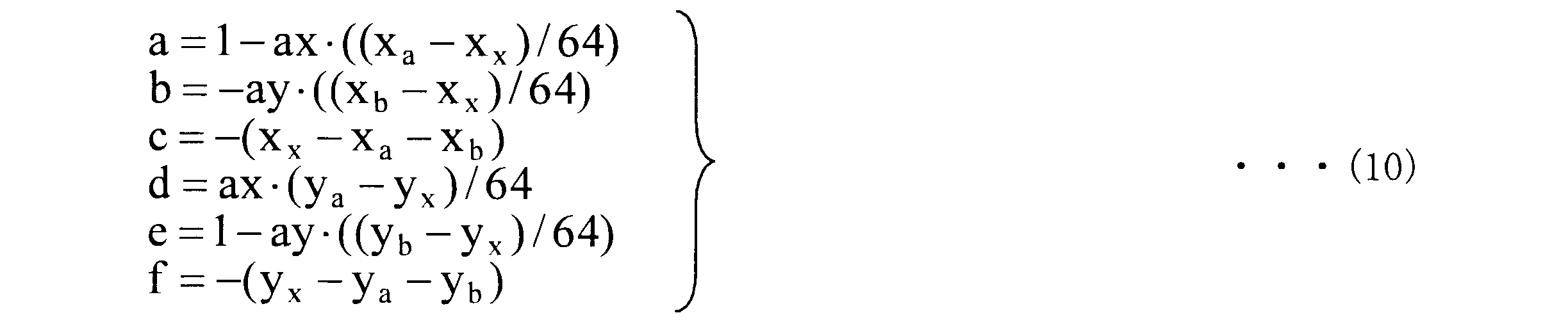

ここで、mb_size_x及びmb_size_yはマクロブロックの水平、垂直方向のサイズを示しており、16×16画素ブロックの場合には、mb_size_x=16、mb_size_y=16となる。また、blk_size_x及びblk_size_yは予測対象ブロックの水平、垂直サイズを表しており、図9Bの場合は、blk_size_x=8、blk_size_y=8となる。
ここでは、入力値として隣接ブロックA及びBの動きベクトルを用いて、幾何変換パラメータを導出する例を示したが、必ずしも、隣接ブロックA及びBの動きベクトルを用いる必要はなく、隣接ブロックC、D及びそれ以外の隣接ブロックから算出された動きベクトルを用いても良いし、これらの複数の隣接ブロックの動きベクトルからパラメータフィッティングを用いて、幾何変換パラメータを求めても良い。また、式(10)は、それぞれa,b,d,eが実数で得られるが、予めこれらのパラメータの演算精度を決めておくことで簡単に整数化が可能である。
≪隣接動きベクトルの導出-エッジ考慮≫
隣接ブロックとの境界にオブジェクトのエッジがある場合や、異なるオブジェクトが存在する場合、幾何変換パラメータが正しく導出できないことがある。そこで、利用する隣接動きベクトルと予測対象ブロックの動きベクトルの絶対差分値が大きく異なる場合は、当該隣接ブロックの動きベクトルを入力値に加えない処理を行ってもよい。例えば、|mva-mvx|を計算し、予め規定した閾値Dよりも大きくなる場合は、mvaを入力値として利用しないようにしてもよい。
隣接ブロックとの境界にオブジェクトのエッジがある場合や、異なるオブジェクトが存在する場合、幾何変換パラメータが正しく導出できないことがある。そこで、利用する隣接動きベクトルと予測対象ブロックの動きベクトルの絶対差分値が大きく異なる場合は、当該隣接ブロックの動きベクトルを入力値に加えない処理を行ってもよい。例えば、|mva-mvx|を計算し、予め規定した閾値Dよりも大きくなる場合は、mvaを入力値として利用しないようにしてもよい。
また、予測対象ブロックの左に位置する隣接ブロックの候補が複数存在する場合、これらの候補の中で動きベクトルのメディアン値を計算し、値が大きく異なる動きベクトルを除外してもよい。図12は、4つの8×8画素ブロック毎に、メディアン値を計算する例を示す図である。予測対象ブロックXのブロックサイズが大きく、隣接する画素ブロックのブロックサイズが小さい場合、隣接画素の候補となる画素ブロックが複数存在する。ここで、左に位置する4個の画素ブロックの動きベクトルを、それぞれ、mva、mvb、mvc、mvdとすると、次式(12)により動きベクトルを決定する。


この他に、要素毎の平均値、二次元ベクトルのランダム値、又は、ベクトルの要素別のランダム値等を用いてもよい。また、隣接ブロックB、C、Dにおいても同様の処理を行って隣接動きベクトルを求めてもよい。
≪予測対象画素の分割≫
次に予測対象ブロックに対して幾何変換を実施する領域を説明する。幾何変換パラメータを導出する領域は、幾何変換を実施する領域に対応している。式(10)では矩形画素ブロックに対して幾何変換パラメータを導出する例を示した。しかし、必ずしも矩形画素ブロックで幾何変換パラメータを導出する必要はなく、図13で示す三角パッチで矩形ブロックを分割してもよい。図13A、及び、図13Bは予測対象ブロックを対角線で分け2つの三角パッチで分割した例を示している。図13Aでは、それぞれの幾何変換パラメータを次式で導出する。予測対象三角パッチX1は、隣接ブロックA、D及び予測対象ブロックX1の動きベクトルを用いて次式(14)で定義される。
次に予測対象ブロックに対して幾何変換を実施する領域を説明する。幾何変換パラメータを導出する領域は、幾何変換を実施する領域に対応している。式(10)では矩形画素ブロックに対して幾何変換パラメータを導出する例を示した。しかし、必ずしも矩形画素ブロックで幾何変換パラメータを導出する必要はなく、図13で示す三角パッチで矩形ブロックを分割してもよい。図13A、及び、図13Bは予測対象ブロックを対角線で分け2つの三角パッチで分割した例を示している。図13Aでは、それぞれの幾何変換パラメータを次式で導出する。予測対象三角パッチX1は、隣接ブロックA、D及び予測対象ブロックX1の動きベクトルを用いて次式(14)で定義される。
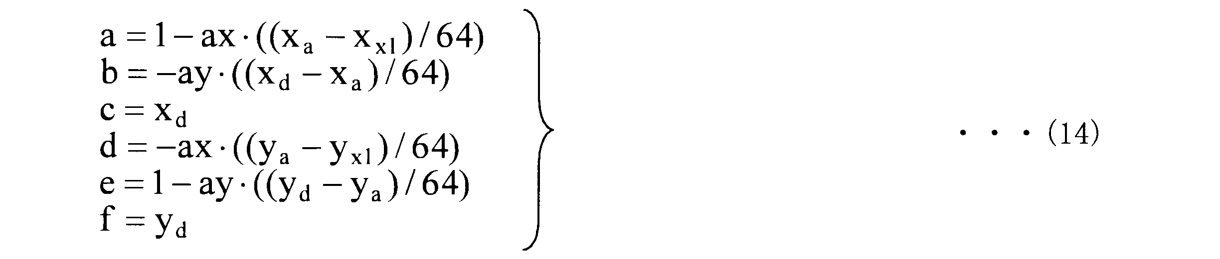

式(14)及び式(15)に示す例のように、予測対象三角パッチ(または予測対象ブロック)に対して空間的距離の近い隣接ブロックの動きベクトルを用いて幾何変換パラメータを導出する。
図13Bの場合も、同様にして、幾何変換パラメータが導出できる。しかし、予測対象三角パッチX2は、未符号化画素ブロック側に空間的距離が近く、隣接ブロックとの空間的距離が遠い。一般的に、オブジェクトの動きは空間的相関が高いため、利用可能な隣接ブロックが多く取れるように分割形状を定義するとよい。
なお、本実施形態では、予測対象ブロックを2つの三角パッチで分割する例を示したが、分割形状は、更に複数の三角パッチで分割してもよく、また、矩形、曲線、台形、平行四辺形、及びこれらの組み合わせを用いて分割しても良い。
本実施形態では、幾何変換の例としてアフィン変換を用いた例を示したが、共一次変換、ヘルマート変換、二次等角変換、射影変換、3次元射影変換、などのいずれの幾何変換を用いてもよい。例えば射影変換は、次式(16)で表される。

式(16)において、分子分母をスカラーで通分すると、解くべきパラメータは8種類となる。そこで、利用可能な隣接ブロック数を多く定義することにより、アフィン変換と同様の枠組みで幾何変換パラメータを導出することが可能である。
以上が、幾何変換パラメータ導出部108の処理の概要である。
以上が、幾何変換パラメータ導出部108の処理の概要である。
<幾何変換予測部109>
次に、幾何変換予測部109の処理について具体的に説明する。幾何変換予測部109は入力された幾何変換パラメータ121を基にして、参照画像信号120に対して幾何変換を実施し、幾何変換予測を行う。図14は、幾何変換予測部109の構成の例を示すブロック図である。幾何変換予測部109は、幾何変換部191と内挿補間部192とを有する。幾何変換部191は、参照画像信号120に対する幾何変換を行い、予測画素の位置を算出する。内挿補間部192は、幾何変換により求められた予測画素の分数位置に対応する予測画素の値を、内挿補間等により算出する。
次に、幾何変換予測部109の処理について具体的に説明する。幾何変換予測部109は入力された幾何変換パラメータ121を基にして、参照画像信号120に対して幾何変換を実施し、幾何変換予測を行う。図14は、幾何変換予測部109の構成の例を示すブロック図である。幾何変換予測部109は、幾何変換部191と内挿補間部192とを有する。幾何変換部191は、参照画像信号120に対する幾何変換を行い、予測画素の位置を算出する。内挿補間部192は、幾何変換により求められた予測画素の分数位置に対応する予測画素の値を、内挿補間等により算出する。
図15は、予測対象ブロックに対する幾何変換予測と動き補償予測の例を示す図である。図15は、16×16画素ブロックの例である。
図中、予測対象ブロックは三角で示される画素からなる正方形画素ブロックCRである。動き補償予測の対応する画素は黒丸で示される。黒丸で示される画素からなる画素ブロックMERは、正方形である。一方、幾何変換予測の対応する画素は×で示され、これらの画素からなる画素ブロックGTRは、平行四辺形となる。
動き補償後の領域と幾何変換後の領域は、参照画像信号の対応する領域を符号化対象のフレームの座標に合わせて記述している。このように、幾何変換予測を用いることによって、矩形画素ブロックの回転、拡大・縮小、せん断、鏡面変換などの変形に合わせた予測画像信号の生成が可能となる。
幾何変換部191は、式(10)、式(14)、及び、式(15)を用いて算出された幾何変換パラメータ121を用い、式(9)により、幾何変換後の座標(u,v)を算出する。算出された幾何変換後の座標(u,v)は、実数値である。そこで、座標(u,v)に対応する輝度値を参照画像信号から内挿補間することによって予測値を生成する。
式(10)、式(14)、及び、式(15)より、6ビット演算で誤差なく分数位置を計算できるため、内挿補間の際の画素精度を6ビットとする。これにより、整数画素間は64個の分数画素に分割される。
図16は、共一次内挿法による輝度値補間処理の例を示す図である。白丸cw0ないしcw3は整数画素位置の輝度値を示し、黒丸cbが補間画素位置(u,v)を示している。図16では、分数精度の位置に隣接する周囲4つの整数画素値を用いて、それぞれの距離の比から補間画素値を生成する。共一次内挿法は次式(17)で表される。

ここでP(u,v)は内挿補間処理後の予測画素値を示しており、R(x,y)は、利用した参照画像信号の整数画素値を表している。(x-u)=U/64、(y-v)=V/64とすると、式(17)は、式(18)に示す整数演算に変形できる。

以上のように、幾何変換を行った予測対象ブロック内の座標毎に内挿補間を適用することによって、新たな予測画像信号を生成する。
なお、本実施形態では、内挿補間の方法として共一次内挿法を用いる例を示したが、最近接内挿法、3次畳み込み内挿法、線形フィルタ内挿法、ラグランジュ補間法、スプライン補間法、ランツォシュ補間法などのいかなる内挿補間法を適用しても構わない。
なお、本実施形態では、参照画像信号の整数画素位置からの内挿補間についての例を説明したが、動き推定部106で、既に参照画像信号120の補間画像信号を保持している場合には、分数精度の補間画像信号を再利用しても良い。例えば、動き推定部106で1/4画素精度の動きベクトルを算出する際に、参照画像信号を4倍に拡大した拡大参照画像信号を生成して保持している場合には、1/4画素精度の補間画像を利用して1/64画素精度の補間画像を生成してもよい。これにより、1/4精度の補間画像から更に1/16精度の内挿補間処理を行って1/64画素精度の補間画像を生成することができる。なお、内挿補間処理の画素精度は更に細かく指定することも可能である。この場合、指定した補間精度に応じて内挿補間処理を行えばよい。
以上が、幾何変換予測部109の処理の概要である。
以上が、幾何変換予測部109の処理の概要である。
<判定パラメータ導出部127>
次に判定パラメータ導出部127について具体的に説明する。判定パラメータ導出部127は、幾何変換パラメータ導出部108から出力された幾何変換パラメータ121を用いて、動き補償予測部107から出力された予測画像信号と幾何変換予測部109から出力された予測画像信号との何れの信号を出力するかを判定するための判定パラメータ125を生成し、予測切替部111へと出力する。幾何変換がアフィン変換の場合には、平行移動指標、回転指標、拡大・縮小指標、変形指標などを用いて、幾何変換の度合いを評価することができる。
次に判定パラメータ導出部127について具体的に説明する。判定パラメータ導出部127は、幾何変換パラメータ導出部108から出力された幾何変換パラメータ121を用いて、動き補償予測部107から出力された予測画像信号と幾何変換予測部109から出力された予測画像信号との何れの信号を出力するかを判定するための判定パラメータ125を生成し、予測切替部111へと出力する。幾何変換がアフィン変換の場合には、平行移動指標、回転指標、拡大・縮小指標、変形指標などを用いて、幾何変換の度合いを評価することができる。
一般的な動画像では、時間方向への相関が高い。動きベクトルは時間的に異なる画像間のオブジェクトの移動を示す値であるため、動きの空間相関も比較的高いことが予想される。そこでこれらの指標を判定パラメータとして利用し、予測方法を動的に切り替える。平行移動指標は次式(19)で与えられる。

式(19)において、cnは、隣接ブロック、又は、予測対象ブロックを分割した隣接する三角パッチ、すなわち、図13における同じ番号の隣接ブロック内の三角パッチの幾何変換パラメータのc成分を示しており、cxは隣接ブロックの幾何変換パラメータのc成分を示している。三角パッチに分割した際は、分割した同じ形状の三角パッチとの隣接関係を参照している。f成分についても同様である。
図17は、アフィン変換による画素ブロックの変化の例を示す図である。図17では、座標(1,0)及び(0,1)がそれぞれアフィン変換によって座標(a,d)、(b、c)に変換され、変換前のベクトルの中心角度45°からθD回転している。a,b,d,eはそれぞれ、予測対象ブロックで得られた幾何変換パラメータを示している。回転指標は次式(20)で与えられる。

拡大・縮小指標は図17で示されるアフィン変換後の面積に相当し、値が1より大きい場合は拡大方向に、小さい場合は縮小方向に変形していることが判る。そこで、次式で拡大・縮小指標を定義する。



また、式(24)に示す、隣接ブロックで算出された幾何変換パラメータの各成分と予測対象ブロックで算出された幾何変換パラメータの各成分の差分値もそれぞれ判定パラメータの1つのパラメータとしている。

また、式(20)、式(21)、式(22)、式(23)を用いて算出された予測対象ブロックと隣接ブロックの指標を用いて以下のような判定パラメータを利用しても良い。



例えばDetnは隣接ブロック或いは隣接ブロックの三角パッチが保持する幾何変換パラメータから算出される。算出された幾何変換パラメータに対応する指標と幾何変換パラメータの差分値が判定パラメータ125として、予測切替部111へと出力される。
以上が、判定パラメータ導出部127の処理の概要である。
以上が、判定パラメータ導出部127の処理の概要である。
<予測切替部111-予測の動的切替>
次に予測切替部111について具体的に説明する。予測切替部111は、判定パラメータ導出部127から出力された判定パラメータ125に基づいて、どちらの予測画像信号を用いたかが記載された予測切替情報122を生成する。
次に予測切替部111について具体的に説明する。予測切替部111は、判定パラメータ導出部127から出力された判定パラメータ125に基づいて、どちらの予測画像信号を用いたかが記載された予測切替情報122を生成する。
先ず、式(20)ないし式(23)を用いる場合の切替方法について説明する。回転指標、拡大・縮小指標、変形指標は、動きベクトルのみの平行移動に加え、画素ブロックの回転、拡大、縮小、変形の度合いを図る指標である。算出された幾何変換パラメータの指標が、極端に大きい場合や小さい場合には、幾何変換パラメータの推定が不適切であることが予想され、このパラメータを利用して幾何変換予測で生成される予測画像信号は誤差を多く含んでいることが予想される。そこで、これらの指標が、予め定めた閾値の範囲を超えた場合には、幾何変換予測の予測画像信号を利用しないように予測切替情報122を生成する。例として、式(21)の拡大・縮小指標における閾値範囲について説明する。Detは拡大・縮小の度合いを示す指標である。予測切替情報122を次式(28)で定義する。

ここでpred_flagは予測切替情報122を表しており、ThDetは閾値を表している。Detがそれぞれ閾値の範囲を超えた場合、pred_flagは0となり、動き補償予測を選択する。一方、それ以外の場合は、pred_flagは1となり、幾何変換予測を選択する。他の判定パラメータに関しても同様な閾値判定を行い、予測切替情報122を生成する。
次に、式(19)、式(24)ないし式(27)を用いる際の切替方法について説明する。隣接ブロックと予測対象ブロックの幾何変換パラメータには高い空間相関があることが推定されるため、それぞれの差分値が予め定めた閾値の大きさを超える場合には、幾何変換予測の予測画像信号を利用しないように予測切替情報122を生成する。
次に隣接ブロックと予測対象ブロックの符号化パラメータとを用いたときの切替方法について説明する。符号化パラメータに含まれる量子化パラメータは、量子化ステップサイズを規定するパラメータである。量子化パラメータが大きい場合、変換係数が粗く量子化される。これにより、局部復号された参照画像信号が入力画像信号に対して大きな誤差を持ち、動きベクトルの推定精度が低下する。幾何変換予測では、動きベクトルを利用して幾何変換パラメータを算出するため、動きベクトルの推定精度が低下すると幾何変換パラメータの算出精度も低下する。そこで、量子化パラメータが大きくなった場合、各種判定パラメータの閾値範囲を狭くする処理を行う。つまり、各種パラメータの閾値は量子化パラメータに対する減少関数となる。
なお、本実施形態では、量子化パラメータを利用して閾値の範囲を制御する例を示したが、符号化パラメータに含まれる他の情報を用いてもよい。例えば、符号化した動画像の解像度、予測対象ブロックのタイプ、参照画像のRef_idx、動きベクトルの値、又は、変換サイズに関する情報などを利用してもよい。
また、隣接ブロックの全ての隣接動きベクトルと予測対象ブロックの動きベクトルとが同一の値を持つとき、幾何変換前と後での座標が変化しない。このような時は、周辺ブロックが同一のオブジェクトの平行移動と考えられるため、幾何変換予測を行う必要がない。そこで、この条件が成り立つときは、予測切替情報122は、幾何変換予測を利用しない旨の値を有する。
また、それぞれの指標に対して用いる閾値を符号化パラメータの値に応じて変化する関数としてもよい。例えば、式(28)における閾値ThDetを量子化パラメータに依存する関数として定義し、量子化パラメータが増加するに従って、閾値が減少するような関数とすることで、推定精度の低下する低ビットレート帯での効果的な予測切替が可能となる。
以上が、予測切替部111及び予測分離スイッチ110の処理の概要である。
以上が、予測切替部111及び予測分離スイッチ110の処理の概要である。
<幾何変換予測を含むインター予測の処理フロー>
図18は、インター予測部130の予測画像信号生成の処理を示すフロー図である。処理が開始される(S501)と、インター予測部130の外部から入力されてきた予測対象ブロックの動きベクトル119が幾何変換パラメータ導出部108へと入力される。これを受けて幾何変換パラメータ導出部108では、予測対象ブロックに対応する隣接ブロックを決定する(S502)。
図18は、インター予測部130の予測画像信号生成の処理を示すフロー図である。処理が開始される(S501)と、インター予測部130の外部から入力されてきた予測対象ブロックの動きベクトル119が幾何変換パラメータ導出部108へと入力される。これを受けて幾何変換パラメータ導出部108では、予測対象ブロックに対応する隣接ブロックを決定する(S502)。
次に対応する隣接ブロックの隣接動きベクトルを、符号化制御部126が保持する内部メモリS511から導出する(S503)。幾何変換パラメータ導出部108が、導出された隣接動きベクトルと予測対象ブロックの動きベクトルを用いて幾何変換パラメータ121を導出する(S504)。
導出された幾何変換パラメータ121を用いて幾何変換予測部109にて予測対象ブロックの幾何変換処理が行われる(S505)。幾何変換予測部109は、幾何変換によって新たに算出された分数画素位置の予測画像信号を内挿補間によって生成する(S506)。
幾何変換パラメータ導出部108で算出され内部メモリS511に保存された幾何変換パラメータ121は判定パラメータ導出部127へと入力され、判定パラメータ125が算出される(S507)。算出された判定パラメータ125が予測切替部111へと入力され、予測切替情報122が生成される(S508)。
予測対象ブロックで算出された幾何変換パラメータ121が、符号化制御部126内に所持する内部メモリへS511と保存される(S509)。動きベクトル119が符号化制御部126内に所持する内部メモリS511へと保存される(S510)。
予測切替情報122に従って予測分離スイッチ110は、予測対象ブロックの予測方法が、幾何変換予測部109で生成された予測画像信号を利用するかどうかを判断する(S512)。かかる判断がYESの場合、予測分離スイッチ110は、幾何変換予測部109の出力端をスイッチと接続し、予測画像信号を出力する(S513)。
一方、かかる判断がNOの場合、動き補償予測部107では、動きベクトル119に従って動き補償予測処理を行う(S514)。予測分離スイッチ110は動き補償予測部107の出力端へスイッチを接続し、予測画像信号を出力する(S515)。
次に、符号化制御部126は、予測対象ブロックが、マクロブロックにおける最終ブロックであるかどうかを判断し(S516)、かかる判断がYESの場合は、当該マクロブロックの予測処理を終了する(S517)。かかる判断がNOの場合、処理は最初に戻り、マクロブロックの次の画素ブロックの予測画像生成処理を行う。以上が本発明の本実施形態におけるインター予測の予測画像生成処理の流れである。
<シンタクス構造>
次に、動画像符号化装置100におけるシンタクス構造について説明する。図19は、シンタクス1600の構成を示す図である。図19に示すとおり、シンタクス1600は主に3つのパートを有する。ハイレベルシンタクス1601は、スライス以上の上位レイヤのシンタクス情報を有する。スライスレベルシンタクス1602は、スライス毎に復号に必要な情報を有し、マクロブロックレベルシンタクス1603は、マクロブロック毎に復号に必要とされる情報を有する。
次に、動画像符号化装置100におけるシンタクス構造について説明する。図19は、シンタクス1600の構成を示す図である。図19に示すとおり、シンタクス1600は主に3つのパートを有する。ハイレベルシンタクス1601は、スライス以上の上位レイヤのシンタクス情報を有する。スライスレベルシンタクス1602は、スライス毎に復号に必要な情報を有し、マクロブロックレベルシンタクス1603は、マクロブロック毎に復号に必要とされる情報を有する。
各パートは、更に詳細なシンタクスで構成されている。ハイレベルシンタクス1601は、シーケンスパラメータセットシンタクス1604とピクチャパラメータセットシンタクス1605などの、シーケンス及びピクチャレベルのシンタクスを含む。スライスレベルシンタクス1602は、スライスヘッダーシンタクス1606、スライスデータシンタクス1607等を含む。マクロブロックレベルシンタクス1603は、マクロブロックレイヤーシンタクス1608、マクロブロックプレディクションシンタクス1609等を含む。
図20は、スライスヘッダーシンタクス1606の例を示す図である。図中に示されるslice_affine_motion_prediction_flagは、当該スライスに幾何変換予測を適用するかどうかを示すシンタクス要素である。slice_affine_motion_prediction_flagが0である場合、予測切替部111は、当該スライスにおいて常に動き補償予測部107の出力端を出力するように予測切替情報122を設定して予測分離スイッチ110を切り替える。つまり、このスライスに対しては、幾何変換予測を適用しないことを意味する。一方、slice_affine_motion_prediction_flagが1である場合、当該スライスにおいて判定パラメータ125が指し示す情報に基づいて予測切替情報122が設定され、予測分離スイッチ110は予測画像信号を動的に切り替える。
図21は、スライスデータシンタクス1607の例を示す図である。図中に示されるmb_skip_flagは、当該マクロブロックがスキップモードで符号化されているかどうかを示すフラグである。スキップモードである場合、変換係数や動きベクトルなどは符号化されない。
AvailAffineModeは当該マクロブロックで幾何変換予測が利用できるかどうかを示す内部パラメータである。AvailAffineModeが0の場合、判定パラメータ125で算出した各種値によって、幾何変換予測を利用しないように予測切替情報122が設定されていることを意味する。また、隣接ブロックの隣接動きベクトルと予測対象ブロックの動きベクトルが同一の値を持つときもAvailAffineModeは0となる。
一方、AvailAffineModeが1の場合は、幾何変換予測と動き補償予測のどちらを利用するかを示すmb_affine_motion_skip_flagが符号化される。mb_affine_motion_skip_flagが1の場合、当該スキップモードに対して幾何変換予測が適用されることを意味する。mb_affine_motion_skip_flagが0の場合、動き補償予測が適用されることを意味する。
図22は、マクロブロックレイヤーシンタクス1608の例を示す図である。図中に示されるmb_typeは、マクロブロックタイプ情報を示している。すなわち、現在のマクロブロックがイントラ符号化されているか、インター符号化されているか、或いはどのようなブロック形状で予測が行われているか、予測の方向が単方向予測か双方向予測か、などの情報を含んでいる。mb_typeは、マクロブロックプレディクションシンタクスと更にマクロブロック内のサブブロックのシンタクスを示すサブマクロブロックプレディクションシンタクスなどに渡される。
図23は、マクロブロックプレディクションシンタクスの例を示す図である。図中に示されるAvailAffineModeMbは当該画素ブロックで幾何変換予測が利用できるかどうかを示す内部パラメータである。AvailAffineModeMbが0の場合、判定パラメータ125で算出した各種値によって、幾何変換予測を利用しないように予測切替情報122が設定されていることを意味する。また、隣接ブロックの隣接動きベクトルと予測対象ブロックの動きベクトルが同一の値を持つときもAvailAffineModeMbは0となる。
一方、AvailAffineModeMbが1の場合は、幾何変換予測と動き補償予測のどちらを利用するかを示すmb_affine_pred_flagが符号化される。mb_affine_pred_flagが1の場合、当該画素ブロックに対して幾何変換予測が適用されることを意味する。mb_affine_pred_flagが0の場合、動き補償予測が適用されることを意味する。
NumMbPart()は、mb_typeに規定されたブロック分割数を返す内部関数であり、16×16画素ブロックの場合は1、16×8、8×16画素ブロックの場合は2、8×8画素ブロックの場合は4を出力する。
図24は、サブマクロブロックプレディクションシンタクスの例を示す図である。図中に示されるAvailAffineModeSubMbは当該画素ブロックで幾何変換予測が利用できるかどうかを示す内部パラメータである。AvailAffineModeSubMbが0の場合、判定パラメータ125で算出した各種値によって、幾何変換予測を利用しないように予測切替情報122が設定されていることを意味する。また、隣接ブロックの隣接動きベクトルと予測対象ブロックの動きベクトルが同一の値を持つときもAvailAffineModeSubMbは0となる。
一方、AvailAffineModeSubMbが1の場合は、幾何変換予測と動き補償予測のどちらを利用するかを示すmb_affine_pred_flagが符号化される。mb_affine_pred_flagが1の場合、当該画素ブロックに対して幾何変換予測が適用されることを意味する。mb_affine_pred_flagが0の場合、動き補償予測が適用されることを意味する。NumSubMbPart()は、mb_typeに規定されたブロック分割数を返す内部関数である。
図25は、符号化パラメータの例としてのマクロブロックレイヤーシンタクスの例を示す図である。図中に示されるcoded_block_patternは、8×8画素ブロック毎に、変換係数が存在するかどうかを示している。例えばこの値が0である時、対象ブロックに変換係数が存在しないことを意味している。図中のmb_qp_deltaは、量子化パラメータに関する情報を示している。対象ブロックの1つ前に符号化されたブロックの量子化パラメータからの差分値を表している。
図中のref_idx_l0及びref_idx_l1は、インター予測が選択されているときに、対象ブロックがどの参照画像を用いて予測されたか、を表す参照画像のインデックスを示している。図中のmv_l0、mv_l1は動きベクトル情報を示している。図中のtransform_8x8_flagは、対象ブロックが8×8変換であるかどうかを示す変換情報を表している。
なお、図19ないし図25に示すシンタクスの表中の行間には、本実施形態において規定していないシンタクス要素が挿入されてもよく、その他の条件分岐に関する記述が含まれていてもよい。また、シンタクステーブルを複数のテーブルに分割し、または複数のシンタクステーブルを統合してもよい。また、必ずしも同一の用語を用いる必要は無く、利用する形態によって任意に変更してもよい。更に、当該マクロブロックレイヤーシンタクスに記述されている各々のシンタクス要素は、後述するマクロブロックデータシンタクスに明記されるように変更しても良い。
以上が、第1の実施形態に係る動画像符号化装置100の説明である。
以上が、第1の実施形態に係る動画像符号化装置100の説明である。
(第2の実施形態:イントラ予測の追加)
第2の実施形態で用いられる動画像符号化装置200の構造を図26に示す。なお、第1の実施形態と同じ機能を持つブロックには同一の符号を付し、ここでは説明を省略する。図26では、動画像符号化装置100の機能に加え、新たにイントラ予測部201、モード判定部202、予測モード分離スイッチ203が追加されている。
第2の実施形態で用いられる動画像符号化装置200の構造を図26に示す。なお、第1の実施形態と同じ機能を持つブロックには同一の符号を付し、ここでは説明を省略する。図26では、動画像符号化装置100の機能に加え、新たにイントラ予測部201、モード判定部202、予測モード分離スイッチ203が追加されている。
イントラ予測部201は、入力された参照画像信号120を基にして画面内の情報のみを用いた予測画像信号123を生成する。イントラ予測部201における予測モードの例として、H.264のイントラ予測について説明する。H.264のイントラ予測に用いる画素ブロックを、図27Aないし図27Cに示す。図27Aは、16×16画素イントラ予測、図27Bは、4×4画素イントラ予測、図27Cは、8×8画素イントラ予測に用いられる画素ブロックである。H.264は、これら3つのイントラ予測が規定されている。イントラ予測では、参照画像メモリ105に保存されている参照画像信号120から、補間画素を作成し、空間方向にコピーすることによって予測値を生成する。
<モード判定部202>
次にモード判定部202について概要を説明する。モード判定部202は、現在符号化しているスライスの情報に応じて、予測モード切替情報204を予測モード分離スイッチ203へ出力する。予測モード切替情報204には、イントラ予測部201の出力端とインター予測部130の出力端のどちらと、スイッチを繋ぐかの情報が記述されている。
次にモード判定部202について概要を説明する。モード判定部202は、現在符号化しているスライスの情報に応じて、予測モード切替情報204を予測モード分離スイッチ203へ出力する。予測モード切替情報204には、イントラ予測部201の出力端とインター予測部130の出力端のどちらと、スイッチを繋ぐかの情報が記述されている。
次にモード判定部202の機能を説明する。現在符号化しているスライスがイントラ符号化スライスである場合、モード判定部202は、予測モード分離スイッチ203の出力端をイントラ予測部201に接続する。一方、現在符号化しているスライスがインター符号化スライスである場合、モード判定部202は予測モード分離スイッチ203をイントラ予測部201の出力端に繋ぐか、インター予測部130の出力端へ繋ぐかを判定する。
より詳細に説明すると、上記の場合、モード判定部202では、例えば、次式(29)のコストを用いたモード判定を行う。それぞれの予測モードを選択した際に必要となる予測情報に関する符号量、例えば動きベクトル119の符号量やブロック形状の符号量等をOH、入力画像信号114と予測画像信号123の差分絶対和、すなわち、予測誤差信号115の絶対累積和をSADとすると、以下のモード判定式(29)を用いる。

ここでKはコスト、λは定数をそれぞれ表す。λは量子化スケールや量子化パラメータの値に基づいて決められるラグランジュ未定乗数である。式(29)により得られたコストKを基に、モード判定が行われる。すなわち、コストKが最も小さい値を与えるモードが最適な予測モードとして選択される。
モード判定部202においては、式(29)に代えて、(a)予測情報のみ、(b)SADのみ、を用いてモード判定を行ってもよいし、これら(a)、(b)にアダマール変換を施した値、またはそれに近似した値を利用してもよい。さらに、モード判定部202において入力画像信号114のアクテビティ、すなわち、信号値の分散を用いてコストを作成してもよく、また、量子化スケールまたは量子化パラメータを利用してコスト関数を作成してもよい。
さらに別の例として、仮符号化ユニットを用意し、仮符号化ユニットによりある予測モードで生成された予測誤差信号115を実際に符号化した場合の符号量と、入力画像信号114と復号画像信号118との間の二乗誤差を用いてモード判定を行ってもよい。この場合のモード判定式は、次式(30)になる。

式(30)において、Jは符号化コスト、Dは入力画像信号114と復号画像信号118との間の二乗誤差を表す符号化歪みである。一方、Rは仮符号化によって見積もられた符号量を表している。
式(30)の符号化コストJを用いると、予測モード毎に仮符号化と局部復号処理が必要となるため、回路規模または演算量は増大する。反面、より正確な符号量と符号化歪みを用いるため、高い符号化効率を維持することができる。式(30)に代えてRのみ、またはDのみを用いてコストを算出してもよく、また、RまたはDを近似した値を用いてコスト関数を作成してもよい。
以上のようにして、イントラ予測部201で生成された予測画像信号を選ぶか、インター予測部130で生成された予測画像信号を選ぶか、を判断し、予測モード分離スイッチ203の出力端を切り替える。ここで選択された予測モードの予測画像信号123が出力されて、減算器101へ入力されるとともに、加算器104へ出力される。
以上が本発明の本実施形態に係る動画像符号化装置200の処理の説明である。
以上が本発明の本実施形態に係る動画像符号化装置200の処理の説明である。
(第3の実施形態:動きベクトルの再探索)
第3の実施形態で用いられるインター予測部300の構造を図28に示す。なお、第1の実施形態と同じ機能を持つブロックには同一の符号を付し、ここでは、説明を省略する。また、インター予測部300は、インター予測部130と、入出力の信号が同一であるため、動画像符号化装置100及び動画像符号化装置200が有するインター予測部130と置き換えることができる。
第3の実施形態で用いられるインター予測部300の構造を図28に示す。なお、第1の実施形態と同じ機能を持つブロックには同一の符号を付し、ここでは、説明を省略する。また、インター予測部300は、インター予測部130と、入出力の信号が同一であるため、動画像符号化装置100及び動画像符号化装置200が有するインター予測部130と置き換えることができる。
図28では、インター予測部300の機能に加え、新たに動きベクトル再探索部301が追加されている。動きベクトル再探索部301は、入力されてきた動きベクトル119を基準として、更に周辺部分の動きベクトルの再探索を行う。
外部から入力された予測対象ブロックの動きベクトル119と符号化制御部126に保持されていた隣接画素ベクトルとが幾何変換パラメータ導出部108へと入力され、幾何変換パラメータ121が算出される。幾何変換パラメータ121は幾何変換予測部109へと入力されて幾何変換予測が行われ、予測画像信号が生成される。
動きベクトル再探索部301は、入力された動きベクトル119を基準として、符号化制御部126から与えられた探索範囲で予測対象ブロックの動きベクトルを変更し、幾何変換パラメータの再導出を行う。再導出された幾何変換パラメータが幾何変換予測部109へと入力され、再幾何変換予測が行われ、予測画像信号が生成される。このように動きベクトル再探索部301で生成された予測対象ブロックの動きベクトルを用いて、再探索範囲分の幾何変換予測が行われる。
再探索の際に、式(29)又は式(30)を用いてコストが算出され、コストが小さい動きベクトルと予測画像信号のみが残される。再探索範囲内の幾何変換予測が完了すると、最小のコストを与える、動きベクトルと予測画像信号が予測分離スイッチ110へと出力される。予測対象ブロックの動きベクトルを予測誤差が小さくなるように変更することによって符号化効率を向上させることが可能となる。
(第4の実施形態:動きベクトルの差分をシグナリング)
第4の実施形態に係る動画像符号化装置の構成は、第3の実施形態と同一である。第4の実施形態に係る動画像符号化装置は、第3の実施形態における動画像符号化装置の作用に加えて、予測対象ブロックの動きベクトルと再探索によって算出した動きベクトルとの差分を符号化する。動きベクトル再探索部301により再探索された動きベクトルを幾何変換動き補償予測に用いることにより、本来の動きベクトルが予測誤差削減のために変更される。この再探索後の動きベクトルを隣接動きベクトルとして利用すると、後段の幾何変換パラメータの導出が不適切になることがある。
第4の実施形態に係る動画像符号化装置の構成は、第3の実施形態と同一である。第4の実施形態に係る動画像符号化装置は、第3の実施形態における動画像符号化装置の作用に加えて、予測対象ブロックの動きベクトルと再探索によって算出した動きベクトルとの差分を符号化する。動きベクトル再探索部301により再探索された動きベクトルを幾何変換動き補償予測に用いることにより、本来の動きベクトルが予測誤差削減のために変更される。この再探索後の動きベクトルを隣接動きベクトルとして利用すると、後段の幾何変換パラメータの導出が不適切になることがある。
そこで、本来の動きベクトルとそこからのズレ量を別途符号化することで、幾何変換パラメータの導出に必要な再探索後の動きベクトルと、隣接動きベクトルとして必要となる本来の動きベクトルと、が保持される。なお、この符号化処理は、エントロピー符号化部112が行うとよい。
本実施形態に係わるシンタクスの変更を、図29、図30に示す。シンタクス要素に含まれる文字のうち、L0及びl0は参照画像L0上に示される動きベクトルを示し、L1及びl1は参照画像L1上に示される動きベクトルを示す。再探索前の本来の動きベクトルを、mvorg=(mvxorg,mvyorg)とし、再探索後の動きベクトルをmvrefine=(mvxrefine,mvyrefine)とすると、動きベクトルの差分mvd_affine[2]は次式で算出される。

なお、mvd_affine[0]は垂直方向、mvd_affine[1]は水平方向に対応する動きベクトルの差分値であり、シンタクス要素に対応している。なお、ここでは、図29及び図30に示すシンタクスに含まれている文字l0及びl1を省略しているが、式(31)に示す動きベクトルの差分は、L0及びL1のそれぞれのインデックスに対して計算する。また、mvd_l0及びmvd_l1は、それぞれの参照画像信号に対応する動きベクトルと動きベクトルを予測した値との差分を計算することによって計算され、本実施形態では明示しない他の動きベクトルの予測技術を用いて生成される。
予測対象ブロックの符号化が完了すると、再探索前の動きベクトルであるmvorg=(mvxorg,mvyorg)が符号化制御部126の内部メモリへ格納される。このように予測対象ブロックで利用する動きベクトルと、隣接ブロックとなった際に利用される動きベクトルを別々に保持することにより、隣接ブロックからの幾何変換パラメータの誤差の伝播を防ぐことが可能となる。
以上説明したように、第1ないし第4の実施形態では、矩形ブロックに適さない、動きを有するオブジェクトを予測する際に、過度のブロック分割が施されて、ブロック分割情報が増大することを防ぐ。付加的な情報を増加させずに、ブロック内の動領域と背景領域を分離し、それぞれに最適な予測方法を適用することによって、符号化効率を向上させ、さらに、主観画質を向上するという効果を奏する。
<動画像復号化装置>
次に、動画像復号化に関する第5ないし第7の実施形態について述べる。
次に、動画像復号化に関する第5ないし第7の実施形態について述べる。
(第5の実施形態)
図31は、第4の実施形態に従う動画像復号化装置を示している。図31の動画像復号化装置400は、例えば、第1の実施形態に従う動画像符号化装置により生成される符号化データを復号する。
図31は、第4の実施形態に従う動画像復号化装置を示している。図31の動画像復号化装置400は、例えば、第1の実施形態に従う動画像符号化装置により生成される符号化データを復号する。
図31の動画像復号化装置400は、入力バッファ401に蓄えられる符号化データ411を復号し、復号画像信号420を出力バッファ419に出力する。符号化データ411は、例えば、動画像符号化装置100などから送出され、蓄積系または伝送系を経て送られ、入力バッファ401に一度蓄えられ、多重化された符号化データである。
動画像復号化装置400は、符号化データ復号部402、逆量子化・逆変換部403、加算器404、参照画像メモリ405、動き補償予測部406、幾何変換パラメータ導出部407、幾何変換予測部408、判定パラメータ導出部422、予測切替部409、及び、予測分離スイッチ410、を有する。動画像復号化装置400は、また、入力バッファ401、出力バッファ419、及び、復号化制御部421と接続される。
符号化データ復号部402は、符号化データを1フレーム又は1フィールド毎にシンタクスに基づいて構文解析による解読を行う。符号化データ復号部402は、順次各シンタクスの符号列をエントロピー復号化し、動きベクトル415、及び、対象ブロックの符号化パラメータ等を再生する。符号化パラメータとは、予測情報、変換係数に関する情報、量子化に関する情報、等の復号の際に必要になるパラメータである。
符号化データ復号部402で解読が行われた変換係数は、逆量子化・逆変換部403へ入力される。符号化データ復号部402によって解読された量子化に関する様々な情報、すなわち、量子化パラメータや量子化マトリクスは、復号化制御部421の内部メモリに設定され、逆量子化処理として利用される際にロードされる。
ロードされた量子化に関する情報を用いて、逆量子化・逆変換部403では、最初に逆量子化処理が行われる。逆量子化された変換係数は、続いて逆変換処理、例えば逆離散コサイン変換等が実行される。ここでは、逆直交変換について説明したが、符号化装置でウェーブレット変換などが行われている場合には、逆量子化・逆変換部403は、対応する逆量子化及び逆ウェーブレット変換などが実行されるとよい。
逆量子化・逆変換部403を通って、復元された予測誤差信号412は加算器404へと入力される。加算器404は、予測誤差信号412と後述する動き補償予測部406又は幾何変換予測部408で生成された予測画像信号418とを加算し、復号画像信号420を生成する。
生成された復号画像信号420は、動画像復号化装置400から出力されて、出力バッファ419に一旦蓄積された後、復号化制御部421が管理する出力タイミングに従って出力される。また、この復号画像信号420は参照画像メモリ405へと保存され、参照画像信号413となる。
参照画像信号413は参照画像メモリ405から、順次フレーム毎或いはフィールド毎に読み出され、予測動き補償予測部406或いは幾何変換予測部408へと入力される。対象画素ブロックで利用された動きベクトル415及び幾何変換パラメータ414は、復号化制御部421に保存され、後述する幾何変換パラメータ導出部108、判定パラメータ導出部422で適宜ロードされて利用される。
なお、図31の動き補償予測部406、幾何変換パラメータ導出部407、幾何変換予測部408、判定パラメータ導出部422、予測切替部409、及び、予測分離スイッチ410は、それぞれ、図2に示す同名の各部と同一の機能及び構成を有する。より詳細には、動き補償予測部107に入力される動きベクトルが、動き推定部106によって取得されたものであるのに対し、動き補償予測部406に入力される動きベクトルは、符号化データ復号部402によって復号されたものであることが異なる他は、全て同一である。
図32は、図31における、動き補償予測部406、幾何変換パラメータ導出部407、幾何変換予測部408、判定パラメータ導出部422、予測切替部409、及び、予測分離スイッチ410を、インター予測部130と置き換えた例を示す図である。これらの各部は、図2に示すインター予測部130が有する各部と同一の機能及び構成を有する。したがって、動画像符号化装置100が有するインター予測部130を、動画像復号化装置400が保持することにより、図31に示す構成を実現することができる。
<幾何変換パラメータ導出部407>
幾何変換パラメータ導出部407では、符号化データ復号部402が復号した予測対象ブロックの動きベクトル415と復号化制御部421に保存されている動きベクトル(以下、「隣接動きベクトル」という。)とを用いて、予測対象ブロックの幾何変換パラメータを導出する。
幾何変換パラメータ導出部407では、符号化データ復号部402が復号した予測対象ブロックの動きベクトル415と復号化制御部421に保存されている動きベクトル(以下、「隣接動きベクトル」という。)とを用いて、予測対象ブロックの幾何変換パラメータを導出する。
予測対象ブロックに対する隣接ブロックの関係を、図4、及び、図9ないし図13を用いて説明する。なお、図4及び図9ないし図13の説明において、第1ないし第4の実施形態における「符号化又は予測対象となるブロック」、「符号化又は予測が完了した画素ブロック」及び「未符号化又は未予測画素ブロック」を、第5ないし第7の実施形態では、それぞれ、「復号化又は予測対象となるブロック」、「復号化又は予測が完了した画素ブロック」及び「未復号化又は未予測画素ブロック」と読み替える。
≪隣接ブロックと隣接動きベクトルの導出(その1)-ブロックサイズが同じ場合≫
図9Aないし図9Eは、予測対象ブロックに対する隣接ブロックの関係を説明する図である。図9Aでは、予測対象ブロックと隣接ブロックのサイズ(例えば16×16画素ブロック)が一致する場合の例を示す。
図9Aないし図9Eは、予測対象ブロックに対する隣接ブロックの関係を説明する図である。図9Aでは、予測対象ブロックと隣接ブロックのサイズ(例えば16×16画素ブロック)が一致する場合の例を示す。
図9A中、斜線のハッチングが付された画素ブロックpは、既に復号化又は予測が完了している画素ブロック(以下、「予測済画素ブロック」という。)であり、ドットのハッチングが付されたブロックcは予測対象ブロックであり、白で表示されている画素ブロックnは未復号化画素(未予測)ブロックである。図中Xは復号化(予測)対象画素ブロックを表している。
隣接ブロックAは、予測対象ブロックXの左の隣接ブロック、隣接ブロックBは、予測対象ブロックXの上の隣接ブロック、隣接ブロックCは、予測対象ブロックXの右上の隣接ブロック、隣接ブロックDは、予測対象ブロックXの左上の隣接ブロックである。
復号化制御部421の内部メモリに保持されている隣接動きベクトルは、予測済画素ブロックの動きベクトルのみである。図4では、復号化処理をされている復号化フレームfにおいて、復号化対象となるブロックcよりも左及び上に位置するブロックが、復号済みブロックpである。図4で示したように画素ブロックは左上から右下に向かって復号化及び予測の処理がされていくため、画素ブロックXの予測を行う際には、右及び下方向の画素ブロックは未だ復号化が行われていない。そこで、これらの隣接ブロックから隣接動きベクトルを導出することができない。
図9Bないし図9Eは、予測対象ブロックが8×8画素ブロックの場合の、隣接ブロックの例を示す図である。なお、図9Bないし図9Eにおいて、太線はマクロブロックの境界を表す。図9Bは、マクロブロック内の左上に位置する画素ブロック、図9Cは、マクロブロック内の右上に位置する画素ブロック、図9Dは、マクロブロック内の左下に位置する画素ブロック、図9Eは、マクロブロック内の右下に位置する画素ブロックを、それぞれ、予測対象ブロックとする場合の例を示す。
マクロブロックの内部も同様に左上から右下に向かって復号化処理が行われるため、8×8画素ブロックの復号化順序に応じて隣接ブロックの位置が変化する。対応する8×8画素ブロックの復号化処理又は予測画像生成処理が完了すると、その画素ブロックは復号化済み画素ブロックとなり、後に処理される画素ブロックの隣接ブロックとして利用される。図9Eでは、隣接ブロックCに対応する右上の画素ブロックが未復号化画素ブロックであるため、復号化済み画素ブロックの右上に位置する画素ブロックを隣接ブロックとする。
≪隣接ブロックと隣接動きベクトルの導出(その2)-ブロックサイズが異なる場合≫
次に隣接ブロックと予測対象ブロックのブロックサイズが異なる場合の隣接ブロックの関係を説明する。予測対象ブロックと隣接ブロックのブロックサイズが異なる場合、隣接画素の定義が複数存在する。
次に隣接ブロックと予測対象ブロックのブロックサイズが異なる場合の隣接ブロックの関係を説明する。予測対象ブロックと隣接ブロックのブロックサイズが異なる場合、隣接画素の定義が複数存在する。
図10Aないし図10Dは、予測対象ブロックが大きく、隣接ブロックが小さい場合の例を説明する図である。図10Aは、予測対象ブロックの左上の画素にもっとも近い画素が存在する画素ブロックを隣接画素とする例である。図10Bは、予測対象ブロックに隣接する画素ブロックの右下に位置する画素ブロックを隣接ブロックとする例である。
図10Cは、予測対象ブロックに隣接する画素ブロックの中心に存在する画素ブロックを隣接ブロックとする例である。図10Cでは、予測対象ブロックXの左に隣接する画素ブロックの中心は、8×8画素ブロックの境界となる。このように中心位置がブロック境界に存在する場合は、左の画素ブロックを隣接ブロックとしている。
図10Dは、予測対象ブロックに隣接する画素ブロックの中心に存在する画素ブロックを隣接ブロックとする例であるが、図10Cと同様に中心点が画素ブロック境界に位置するため、中心点の右上に位置する画素ブロックを隣接ブロックとする例である。中心がブロック境界に存在する場合、隣接するどのブロックを中心のブロックと定義しても良いが、全ての隣接画素で同様の定義を適用する。これにより、それぞれの隣接ブロックの動き情報から、予測対象ブロックの動き情報を推定する際に、隣接ブロックに対する位置関係を同一の位相で表現することができる。
尚、本実施形態では、簡単のために図10Aで示された隣接ブロックの定義を利用する。
図11Aないし図11Dは、予測対象ブロックが小さく、隣接ブロックのブロックサイズが大きい場合の例を説明する図である。図9Eと同様に、対応する画素ブロックが未復号化画素ブロックである場合は、予測対象ブロックに距離的に近い利用可能な復号化済みの画素ブロックで置き換える。
以上の説明では、16×16画素及び8×8画素の場合を例に挙げて説明したが、同様の枠組みを用いて32×32画素、4×4画素などの正方画素ブロックや16×8画素、8×16画素などの矩形画素ブロックに対しても隣接ブロックを決定してよい。
また、インター予測では、マクロブロック内の復号化順序に依存せずに復号化処理、すなわち、動きベクトルの推定を行うことが可能なため、8×8画素ブロックの場合においても、図10Aないし図10Dのいずれかを用いて隣接ブロックを決定してもよい。また、ブロックサイズの大きさが異なる画素ブロックが混在している場合にも、図10Aないし図10Dのいずれかを用いて隣接ブロックを決定してもよい。
なお、隣接ブロックとしてA,B,C,Dの4つの画素ブロックを用いる他に、隣接ブロックを更に広く定義してもかまわない。例えば、隣接ブロックAの更に左の画素ブロックを用いてもよいし、隣接ブロックBの更に上の画素ブロックを用いても良い。これらの隣接ブロックの定義は、既に説明した図9ないし図11の定義と同様に定義してよい。
≪幾何変換パラメータの導出≫
次に幾何変換パラメータ導出部407における幾何変換パラメータ414の導出方法について説明する。隣接ブロックが保持する隣接動きベクトルをそれぞれ式(4)ないし(7)により定義する。
次に幾何変換パラメータ導出部407における幾何変換パラメータ414の導出方法について説明する。隣接ブロックが保持する隣接動きベクトルをそれぞれ式(4)ないし(7)により定義する。
また、動き推定部106から提供される動きベクトル119を式(8)により定義する。なお、動きベクトル119は、予測対象ブロックXの動きベクトルである。
式(4)ないし(8)で表される動きベクトル及び隣接動きベクトルを用いて、幾何変換パラメータ121を導出する。幾何変換がアフィン変換の場合には、変換式は式(9)で表される。式(9)では、座標(x、y)がアフィン変換によって座標(u,v)へ変換される。式(9)に含まれるa、b、c、d、e、fの6個のパラメータが幾何変換パラメータを表している。アフィン変換ではこの6種類のパラメータを推定するため、6個以上の入力値が必要となる。
隣接ブロックA、B及び予測対象ブロックXのそれぞれの動きベクトルを用いると、式(10)により幾何変換パラメータが導出される。ここでは、動きベクトルが1/4精度であることを前提としている。但し、ax、ayは予測対象ブロックのサイズに基づく変数であり、式(11)により算出される。
式(11)において、mb_size_x及びmb_size_yはマクロブロックの水平、垂直方向のサイズを示しており、16×16画素ブロックの場合には、mb_size_x=16、mb_size_y=16となる。また、blk_size_x及びblk_size_yは予測対象ブロックの水平、垂直サイズを表しており、図9Bの場合は、blk_size_x=8、blk_size_y=8となる。
ここでは、入力値として隣接ブロックA及びBの動きベクトルを用いて、幾何変換パラメータを導出する例を示したが、必ずしも、隣接ブロックA及びBの動きベクトルを用いる必要はなく、隣接ブロックC、D及びそれ以外の隣接ブロックから算出された動きベクトルを用いても良いし、これらの複数の隣接ブロックの動きベクトルからパラメータフィッティングを用いて、幾何変換パラメータを求めても良い。また、式(10)は、それぞれa,b,d,eが実数で得られるが、予めこれらのパラメータの演算精度を決めておくことで簡単に整数化が可能である。
≪隣接動きベクトルの導出-エッジ考慮≫
隣接ブロックとの境界にオブジェクトのエッジがある場合や、異なるオブジェクトが存在する場合、幾何変換パラメータが正しく導出できないことがある。そこで、利用する隣接動きベクトルと予測対象ブロックの動きベクトルの絶対差分値が大きく異なる場合は、当該隣接ブロックの動きベクトルを入力値に加えない処理を行ってもよい。例えば、|mva-mvx|を計算し、予め規定した閾値Dよりも大きくなる場合は、mvaを入力値として利用しないようにしてもよい。
隣接ブロックとの境界にオブジェクトのエッジがある場合や、異なるオブジェクトが存在する場合、幾何変換パラメータが正しく導出できないことがある。そこで、利用する隣接動きベクトルと予測対象ブロックの動きベクトルの絶対差分値が大きく異なる場合は、当該隣接ブロックの動きベクトルを入力値に加えない処理を行ってもよい。例えば、|mva-mvx|を計算し、予め規定した閾値Dよりも大きくなる場合は、mvaを入力値として利用しないようにしてもよい。
また、予測対象ブロックの左に位置する隣接ブロックの候補が複数存在する場合、これらの候補の中で動きベクトルのメディアン値を計算し、値が大きく異なる動きベクトルを除外してもよい。図12は、4つの8×8画素ブロック毎に、メディアン値を計算する例を示す図である。予測対象ブロックXのブロックサイズが大きく、隣接する画素ブロックのブロックサイズが小さい場合、隣接画素の候補となる画素ブロックが複数存在する。ここで、左に位置する4個の画素ブロックの動きベクトルを、それぞれ、mva、mvb、mvc、mvdとすると、式(12)により動きベクトルを決定する。
式(12)では、二次元ベクトルのメディアン値を用いる例を示したが、式(13)に示すように、ベクトルの要素毎のメディアン値でもよい。この他に、要素毎の平均値、二次元ベクトルのランダム値、又は、ベクトルの要素別のランダム値等を用いてもよい。また、隣接ブロックB、C、Dにおいても同様の処理を行って隣接動きベクトルを求めてもよい。
≪予測対象画素の分割≫
次に予測対象ブロックに対して幾何変換を実施する領域を説明する。幾何変換パラメータを導出する領域は、幾何変換を実施する領域に対応している。式(10)では矩形画素ブロックに対して幾何変換パラメータを導出する例を示した。しかし、必ずしも矩形画素ブロックで幾何変換パラメータを導出する必要はなく、図13で示す三角パッチで矩形ブロックを分割してもよい。図13A、及び、図13Bは予測対象ブロックを対角線で分け2つの三角パッチで分割した例を示している。図13Aでは、それぞれの幾何変換パラメータを次式で導出する。予測対象三角パッチX1は、隣接ブロックA、D及び予測対象ブロックX1の動きベクトルを用いて式(14)で定義される。
予測対象三角パッチX2は、隣接ブロックB、D及び予測対象ブロックX2の動きベクトルを用いて式(15)で定義される。
次に予測対象ブロックに対して幾何変換を実施する領域を説明する。幾何変換パラメータを導出する領域は、幾何変換を実施する領域に対応している。式(10)では矩形画素ブロックに対して幾何変換パラメータを導出する例を示した。しかし、必ずしも矩形画素ブロックで幾何変換パラメータを導出する必要はなく、図13で示す三角パッチで矩形ブロックを分割してもよい。図13A、及び、図13Bは予測対象ブロックを対角線で分け2つの三角パッチで分割した例を示している。図13Aでは、それぞれの幾何変換パラメータを次式で導出する。予測対象三角パッチX1は、隣接ブロックA、D及び予測対象ブロックX1の動きベクトルを用いて式(14)で定義される。
予測対象三角パッチX2は、隣接ブロックB、D及び予測対象ブロックX2の動きベクトルを用いて式(15)で定義される。
式(14)及び式(15)に示す例のように、予測対象三角パッチ(または予測対象ブロック)に対して空間的距離の近い隣接ブロックの動きベクトルを用いて幾何変換パラメータを導出する。
図13Bの場合も、同様にして、幾何変換パラメータが導出できる。しかし、予測対象三角パッチX2は、未復号化画素ブロック側に空間的距離が近く、隣接ブロックとの空間的距離が遠い。一般的に、オブジェクトの動きは空間的相関が高いため、利用可能な隣接ブロックが多く取れるように分割形状を定義するとよい。
なお、本実施形態では、予測対象ブロックを2つの三角パッチで分割する例を示したが、分割形状は、更に複数の三角パッチで分割してもよく、また、矩形、曲線、台形、平行四辺形、及びこれらの組み合わせを用いて分割しても良い。
本実施形態では、幾何変換の例としてアフィン変換を用いた例を示したが、共一次変換、ヘルマート変換、二次等角変換、射影変換、3次元射影変換、などのいずれの幾何変換を用いてもよい。例えば射影変換は、式(16)で表される。
式(16)において、分子分母をスカラーで通分すると、解くべきパラメータは8種類となる。そこで、利用可能な隣接ブロック数を多く定義することにより、アフィン変換と同様の枠組みで幾何変換パラメータを導出することが可能である。
以上が、幾何変換パラメータ導出部407の処理の概要である。
<幾何変換予測部408>
次に、幾何変換予測部408の処理について、図15ないし図17を用いて説明する。なお、図15ないし図17の説明において、第1ないし第4の実施形態における「参照画像信号120」は、局所復号画像であったのに対し、第5ないし第7の実施形態では、「参照画像信号413」は、復号画像である。
次に、幾何変換予測部408の処理について、図15ないし図17を用いて説明する。なお、図15ないし図17の説明において、第1ないし第4の実施形態における「参照画像信号120」は、局所復号画像であったのに対し、第5ないし第7の実施形態では、「参照画像信号413」は、復号画像である。
幾何変換予測部408は入力された幾何変換パラメータ414を基にして、参照画像信号413に対して幾何変換を実施する。図15は、予測対象ブロックに対する幾何変換予測と動き補償予測の例を示す図である。図15は、16×16画素ブロックの例である。
図中、予測対象ブロックは三角で示される画素からなる正方形画素ブロックCRである。動き補償予測の対応する画素は黒丸で示される。黒丸で示される画素からなる画素ブロックMERは、正方形である。一方、幾何変換予測の対応する画素は×で示され、これらの画素からなる画素ブロックGTRは、平行四辺形となる。
動き補償後の領域と幾何変換後の領域は、参照画像信号の対応する領域を復号化対象のフレームの座標に合わせて記述している。このように、幾何変換予測を用いることによって、矩形画素ブロックの回転、拡大・縮小、せん断、鏡面変換などの変形に合わせた予測画像信号の生成が可能となる。
幾何変換予測部109では、式(10)、式(14)、及び、式(15)を用いて算出された幾何変換パラメータ414を用い、式(9)により、幾何変換後の座標(u,v)を算出する。算出された幾何変換後の座標(u,v)は、実数値である。そこで、座標(u,v)に対応する輝度値を参照画像信号から内挿補間することによって予測値を生成する。
式(10)、式(14)、及び、式(15)より、6ビット演算で誤差なく分数位置を計算できるため、内挿補間の際の画素精度を6ビットとする。これにより、整数画素間は64個の分数画素に分割される。
図16は、共一次内挿法による輝度値補間処理の例を示す図である。白丸cw0ないしcw3は整数画素位置の輝度値を示し、黒丸cbが補間画素位置(u,v)を示している。図16では、分数精度の位置に隣接する周囲4つの整数画素値を用いて、それぞれの距離の比から補間画素値を生成する。共一次内挿法は式(17)で表される。
式(17)において、P(u,v)は内挿補間処理後の予測画素値を示しており、R(x,y)は、利用した参照画像信号の整数画素値を表している。(x-u)=U/64、(y-v)=V/64とすると、式(17)は、式(18)に示す整数演算に変形できる。式(18)において、fは丸めのオフセット(0≦f<212)を表している。本実施形態ではf=0としている。
以上のように、幾何変換を行った予測対象ブロック内の座標毎に内挿補間を適用することによって、新たな予測画像信号を生成する。
以上のように、幾何変換を行った予測対象ブロック内の座標毎に内挿補間を適用することによって、新たな予測画像信号を生成する。
なお、本実施形態では、内挿補間の方法として共一次内挿法を用いる例を示したが、最近接内挿法、3次畳み込み内挿法、線形フィルタ内挿法、ラグランジュ補間法、スプライン補間法、ランツォシュ補間法などのいかなる内挿補間法を適用しても構わない。
なお、本実施形態では、参照画像信号413の整数画素位置からの内挿補間についての例を説明したが、動き補償予測部406で、既に参照画像信号413の補間画像信号を生成している場合には、分数精度の補間画像信号を再利用しても良い。例えば、符号化データ復号部402が、1/4画素精度の動きベクトルを復号し、動き補償予測部406が、その動きベクトルに対応する参照画像信号413を4倍に拡大した拡大参照画像信号を生成して保持している場合には、1/4画素精度の補間画像を利用して1/64画素精度の補間画像を生成してもよい。これにより、1/4精度の補間画像から更に1/16精度の内挿補間処理を行って1/64画素精度の補間画像を生成することができる。
なお、内挿補間処理の画素精度は更に細かく指定することも可能である。この場合、指定した補間精度に応じて内挿補間処理を行えばよい。
以上が、幾何変換予測部408の処理の概要である。
以上が、幾何変換予測部408の処理の概要である。
<判定パラメータ導出部422>
次に判定パラメータ導出部422について具体的に説明する。判定パラメータ導出部422は、幾何変換パラメータ導出部407から出力された幾何変換パラメータ414を用いて、動き補償予測部406から出力された予測画像信号と幾何変換予測部408から出力された予測画像信号との何れの信号を出力するかを判定するための判定パラメータ416を生成し、予測切替部409へと出力する。幾何変換がアフィン変換の場合には、平行移動指標、回転指標、拡大・縮小指標、変形指標などを用いて、幾何変換の度合いを評価することができる。
次に判定パラメータ導出部422について具体的に説明する。判定パラメータ導出部422は、幾何変換パラメータ導出部407から出力された幾何変換パラメータ414を用いて、動き補償予測部406から出力された予測画像信号と幾何変換予測部408から出力された予測画像信号との何れの信号を出力するかを判定するための判定パラメータ416を生成し、予測切替部409へと出力する。幾何変換がアフィン変換の場合には、平行移動指標、回転指標、拡大・縮小指標、変形指標などを用いて、幾何変換の度合いを評価することができる。
一般的な動画像では、時間方向への相関が高い。動きベクトルは時間的に異なる画像間のオブジェクトの移動を示す値であるため、動きの空間相関も比較的高いことが予想される。そこでこれらの指標を判定パラメータとして利用し、予測方法を動的に切り替える。平行移動指標は式(19)で与えられる。
式(19)において、cnは、隣接ブロック、又は、予測対象ブロックを分割した隣接する三角パッチ、すなわち、図13における同じ番号の隣接ブロック内の三角パッチの幾何変換パラメータのc成分を示しており、cxは隣接ブロックの幾何変換パラメータのc成分を示している。三角パッチに分割した際は、分割した同じ形状の三角パッチとの隣接関係を参照している。f成分についても同様である。
図17は、アフィン変換による画素ブロックの変化の例を示す図である。図17では、座標(1,0)及び(0,1)がそれぞれアフィン変換によって座標(a,d)、(b、c)に変換され、変換前のベクトルの中心角度45°からθD回転している。a,b,d,eはそれぞれ、予測対象ブロックで得られた幾何変換パラメータを示している。回転指標は式(20)で与えられる。式(20)において、sgn(A)は、Aの符号を返す関数である。矩形ブロックの中心ベクトルがどの程度回転したかを表している。
拡大・縮小指標は図17で示されるアフィン変換後の面積に相当し、値が1より大きい場合は拡大方向に、小さい場合は縮小方向に変形していることが判る。そこで、式(21)で拡大・縮小指標を定義する。式(21)でDet≒1となる場合は、更に式(22)を用いて回転指標を算出してもよい。図17のθCは式(23)の変形指標に対応しており、アフィン変換後の図形の変形角度を定義している。
また、式(24)に示す、隣接ブロックで算出された幾何変換パラメータの各成分と予測対象ブロックで算出された幾何変換パラメータの各成分の差分値もそれぞれ判定パラメータの1つのパラメータとしている。
また、式(20)、式(21)、式(22)、式(23)を用いて算出された予測対象ブロックと隣接ブロックの指標を用いて式(25)ないし式(27)に示す判定パラメータを利用しても良い。
例えばDetnは隣接ブロック或いは隣接ブロックの三角パッチが保持する幾何変換パラメータ414から算出される。算出された幾何変換パラメータに対応する指標と幾何変換パラメータの差分値が判定パラメータ416として、予測切替部409へと出力される。
以上が、判定パラメータ導出部422の処理の概要である。
以上が、判定パラメータ導出部422の処理の概要である。
<予測切替部409-予測の動的切替>
次に予測切替部409について具体的に説明する。予測切替部409は、判定パラメータ導出部422から出力された判定パラメータ416に基づいて、どちらの予測画像信号を用いたかが記載された予測切替情報417を生成する。
次に予測切替部409について具体的に説明する。予測切替部409は、判定パラメータ導出部422から出力された判定パラメータ416に基づいて、どちらの予測画像信号を用いたかが記載された予測切替情報417を生成する。
先ず、式(20)ないし式(23)を用いる場合の切替方法について説明する。回転指標、拡大・縮小指標、変形指標は、動きベクトルのみの平行移動に加え、画素ブロックの回転、拡大、縮小、変形の度合いを図る指標である。算出された幾何変換パラメータの指標が、極端に大きい場合や小さい場合には、幾何変換パラメータの推定が不適切であることが予想され、このパラメータを利用して幾何変換予測で生成される予測画像信号は誤差を多く含んでいることが予想される。そこで、これらの指標が、予め定めた閾値の範囲を超えた場合には、幾何変換予測の予測画像信号を利用しないように予測切替情報417を生成する。
例として、式(21)の拡大・縮小指標における閾値範囲について説明する。Detは拡大・縮小の度合いを示す指標である。予測切替情報417を式(28)で定義する。
式(28)におけるpred_flagは予測切替情報417を表しており、ThDetは閾値を表している。Detがそれぞれ閾値の範囲を超えた場合、pred_flagは0となり、動き補償予測を選択する。一方、それ以外の場合は、pred_flagは1となり、幾何変換予測を選択する。他の判定パラメータに関しても同様な閾値判定を行い、予測切替情報417を生成する。
次に、式(19)、式(24)ないし式(27)を用いる際の切替方法について説明する。隣接ブロックと予測対象ブロックの幾何変換パラメータには高い空間相関があることが推定されるため、それぞれの差分値が予め定めた閾値の大きさを超える場合には、幾何変換予測の予測画像信号を利用しないように予測切替情報417を生成する。
次に隣接ブロックと予測対象ブロックの符号化パラメータとを用いたときの切替方法について説明する。符号化パラメータに含まれる量子化パラメータは、量子化ステップサイズを規定するパラメータである。量子化パラメータが大きい場合、変換係数が粗く量子化される。これにより、局部復号された参照画像信号が入力画像信号に対して大きな誤差を持ち、動きベクトルの推定精度が低下する。幾何変換予測では、動きベクトルを利用して幾何変換パラメータを算出するため、動きベクトルの推定精度が低下すると幾何変換パラメータの算出精度も低下する。そこで、量子化パラメータが大きくなった場合、各種判定パラメータの閾値範囲を狭くする処理を行う。つまり、各種パラメータの閾値は量子化パラメータに対する減少関数となる。
なお、本実施形態では、量子化パラメータを利用して閾値の範囲を制御する例を示したが、符号化パラメータに含まれる他の情報を用いてもよい。例えば、復号化した動画像の解像度、予測対象ブロックのタイプ、参照画像のRef_idx、動きベクトルの値、又は、変換サイズに関する情報などを利用してもよい。
また、隣接ブロックの全ての隣接動きベクトルと予測対象ブロックの動きベクトルとが同一の値を持つとき、幾何変換前と後での座標が変化しない。このような時は、周辺ブロックが同一のオブジェクトの平行移動と考えられるため、幾何変換予測を行う必要がない。そこで、この条件が成り立つときは、予測切替情報417は、幾何変換予測を利用しない旨の値を有する。
また、それぞれの指標に対して用いる閾値を符号化パラメータの値に応じて変化する関数としてもよい。例えば、式(28)における閾値ThDetを量子化パラメータに依存する関数として定義し、量子化パラメータが増加するに従って、閾値が減少するような関数とすることで、推定精度の低下する低ビットレート帯での効果的な予測切替が可能となる。
以上が、予測切替部409及び予測分離スイッチ410の処理の概要である。
<シンタクス構造>
次に、動画像復号化装置400が復号する符号化データのシンタクス構造について説明する。動画像復号化装置400が復号する符号化データ411は、動画像符号化装置100と同一のシンタクス構造を有するとよい。そこで、ここでは、図19ないし図25を用いて説明する。
次に、動画像復号化装置400が復号する符号化データのシンタクス構造について説明する。動画像復号化装置400が復号する符号化データ411は、動画像符号化装置100と同一のシンタクス構造を有するとよい。そこで、ここでは、図19ないし図25を用いて説明する。
図19は、シンタクス1600の構成を示す図である。図19に示すとおり、シンタクス1600は主に3つのパートを有する。ハイレベルシンタクス1601は、スライス以上の上位レイヤのシンタクス情報を有する。スライスレベルシンタクス1602は、スライス毎に復号に必要な情報を有し、マクロブロックレベルシンタクス1603は、マクロブロック毎に復号に必要とされる情報を有する。
各パートは、更に詳細なシンタクスで構成されている。ハイレベルシンタクス1601は、シーケンスパラメータセットシンタクス1604とピクチャパラメータセットシンタクス1605などの、シーケンス及びピクチャレベルのシンタクスを含む。スライスレベルシンタクス1602は、スライスヘッダーシンタクス1606、スライスデータシンタクス1607等を含む。マクロブロックレベルシンタクス1603は、マクロブロックレイヤーシンタクス1608、マクロブロックプレディクションシンタクス1609等を含む。
図20は、スライスヘッダーシンタクス1606の例を示す図である。図中に示されるslice_affine_motion_prediction_flagは、当該スライスに幾何変換予測を適用するかどうかを示すシンタクス要素である。slice_affine_motion_prediction_flagが0である場合、予測切替部409は、当該スライスにおいて常に動き補償予測部406の出力端を出力するように予測切替情報417を設定して予測分離スイッチ410を切り替える。つまり、このスライスに対しては、幾何変換予測を適用しないことを意味する。一方、slice_affine_motion_prediction_flagが1である場合、当該スライスにおいて判定パラメータ416が指し示す情報に基づいて予測切替情報417が設定され、予測分離スイッチ410は予測画像信号を動的に切り替える。
図21は、スライスデータシンタクス1607の例を示す図である。図中に示されるmb_skip_flagは、当該マクロブロックがスキップモードで符号化されているかどうかを示すフラグである。スキップモードである場合、変換係数や動きベクトルなどは符号化されていない。
AvailAffineModeは当該マクロブロックで幾何変換予測が利用できるかどうかを示す内部パラメータである。AvailAffineModeが0の場合、判定パラメータ416で算出した各種値によって、幾何変換予測を利用しないように予測切替情報417が設定されていることを意味する。また、隣接ブロックの隣接動きベクトルと予測対象ブロックの動きベクトルが同一の値を持つときもAvailAffineModeは0となる。
一方、AvailAffineModeが1の場合は、幾何変換予測と動き補償予測のどちらを利用するかを示すmb_affine_motion_skip_flagが符号化されている。mb_affine_motion_skip_flagが1の場合、当該スキップモードに対して幾何変換予測が適用されることを意味する。mb_affine_motion_skip_flagが0の場合、動き補償予測が適用されることを意味する。
図22は、マクロブロックレイヤーシンタクス1608の例を示す図である。図中に示されるmb_typeは、マクロブロックタイプ情報を示している。すなわち、現在のマクロブロックがイントラ符号化されているか、インター符号化されているか、或いはどのようなブロック形状で予測が行われているか、予測の方向が単方向予測か双方向予測か、などの情報を含んでいる。mb_typeは、マクロブロックプレディクションシンタクスと更にマクロブロック内のサブブロックのシンタクスを示すサブマクロブロックプレディクションシンタクスなどに渡される。
図23は、マクロブロックプレディクションシンタクスの例を示す図である。図中に示されるAvailAffineModeMbは当該画素ブロックで幾何変換予測が利用できるかどうかを示す内部パラメータである。AvailAffineModeMbが0の場合、判定パラメータ125で算出した各種値によって、幾何変換予測を利用しないように予測切替情報122が設定されていることを意味する。また、隣接ブロックの隣接動きベクトルと予測対象ブロックの動きベクトルが同一の値を持つときもAvailAffineModeMbは0となる。
一方、AvailAffineModeMbが1の場合は、幾何変換予測と動き補償予測のどちらを利用するかを示すmb_affine_pred_flagが符号化されている。mb_affine_pred_flagが1の場合、当該画素ブロックに対して幾何変換予測が適用されることを意味する。mb_affine_pred_flagが0の場合、動き補償予測が適用されることを意味する。
NumMbPart()は、mb_typeに規定されたブロック分割数を返す内部関数であり、16×16画素ブロックの場合は1、16×8、8×16画素ブロックの場合は2、8×8画素ブロックの場合は4を出力する。
図24は、サブマクロブロックプレディクションシンタクスの例を示す図である。図中に示されるAvailAffineModeSubMbは当該画素ブロックで幾何変換予測が利用できるかどうかを示す内部パラメータである。AvailAffineModeSubMbが0の場合、判定パラメータ125で算出した各種値によって、幾何変換予測を利用しないように予測切替情報417が設定されていることを意味する。また、隣接ブロックの隣接動きベクトルと予測対象ブロックの動きベクトルが同一の値を持つときもAvailAffineModeSubMbは0となる。
一方、AvailAffineModeSubMbが1の場合は、幾何変換予測と動き補償予測のどちらを利用するかを示すmb_affine_pred_flagが符号化されている。mb_affine_pred_flagが1の場合、当該画素ブロックに対して幾何変換予測が適用されることを意味する。mb_affine_pred_flagが0の場合、動き補償予測が適用されることを意味する。NumSubMbPart()は、mb_typeに規定されたブロック分割数を返す内部関数である。
図25は、符号化パラメータの例としてのマクロブロックレイヤーシンタクスの例を示す図である。図中に示されるcoded_block_patternは、8×8画素ブロック毎に、変換係数が存在するかどうかを示している。例えばこの値が0である時、対象ブロックに変換係数が存在しないことを意味している。図中のmb_qp_deltaは、量子化パラメータに関する情報を示している。対象ブロックの1つ前に符号化されたブロックの量子化パラメータからの差分値を表している。
図中のref_idx_l0及びref_idx_l1は、インター予測が選択されているときに、対象ブロックがどの参照画像を用いて予測されたか、を表す参照画像のインデックスを示している。図中のmv_l0、mv_l1は動きベクトル情報を示している。図中のtransform_8x8_flagは、対象ブロックが8×8変換であるかどうかを示す変換情報を表している。
なお、図19ないし図25に示すシンタクスの表中の行間には、本実施形態において規定していないシンタクス要素が挿入されてもよく、その他の条件分岐に関する記述が含まれていてもよい。また、シンタクステーブルを複数のテーブルに分割し、または複数のシンタクステーブルを統合してもよい。また、必ずしも同一の用語を用いる必要は無く、利用する形態によって任意に変更してもよい。更に、当該マクロブロックレイヤーシンタクスに記述されている各々のシンタクス要素は、後述するマクロブロックデータシンタクスに明記されるように変更しても良い。
以上が、動画像復号化装置400の説明である。
(第6の実施形態:イントラ予測の追加)
図33は、第6の実施形態で用いられる動画像復号化装置500の構造を示す図である。図33において、図32の動画像復号化装置400と同位置の機能を持つ各部には同一の符号を付し、ここでは説明を省略する。
図33は、第6の実施形態で用いられる動画像復号化装置500の構造を示す図である。図33において、図32の動画像復号化装置400と同位置の機能を持つ各部には同一の符号を付し、ここでは説明を省略する。
動画像復号化装置500は、動画像復号化装置400が有する各部に加え、イントラ予測部501、及び、予測切替スイッチ502が追加されている。イントラ予測部501は、入力された参照画像信号413を基にして画面内の情報のみを用いた予測画像信号418を生成する。
符号化データ復号部402で復号された予測情報から予測切替情報503が予測切替スイッチ502へと入力される。予測切替情報503には、イントラ予測部501の出力端とインター予測部130の出力端との、どちらとスイッチを繋ぐかの情報が記述されている。
イントラ予測が選択された場合、予測切替スイッチ502は、イントラ予測部501の出力端をスイッチへと接続し、イントラ予測部501で得られた予測画像信号418を加算器404へと出力する。一方、インター予測が選択された場合、インター予測部130の出力端をスイッチへと接続し、インター予測部130で得られた予測画像信号418を加算器404へと出力する。
これにより、イントラ予測部501で生成された予測画像信号を選ぶか、インター予測部130で生成された予測画像信号を選ぶか、が判断され、予測モード分離スイッチ502の出力端を切り替える。
以上が第6の実施形態に係る動画像復号化装置500の処理の説明である。
(第7の実施形態:動きベクトルの差分をシグナリング)
本発明の第7の実施形態に係わる動画像復号化装置は、例えば、第4の実施の動画像復号化装置が生成する符号化データを復号して復号画像信号を生成する。第7の実施形態に係る動画像符号化装置は、第5の実施形態に係わる動画像復号化装置400の機能に加えて、予測対象ブロックの動きベクトルと幾何変換パラメータを補正する動きベクトルの差分を復号化する。
本発明の第7の実施形態に係わる動画像復号化装置は、例えば、第4の実施の動画像復号化装置が生成する符号化データを復号して復号画像信号を生成する。第7の実施形態に係る動画像符号化装置は、第5の実施形態に係わる動画像復号化装置400の機能に加えて、予測対象ブロックの動きベクトルと幾何変換パラメータを補正する動きベクトルの差分を復号化する。
第5の実施形態に係る動画像復号化装置400が復号化する符号化データのシンタクスに対する、本実施形態に係わる動画像復号化装置が復号する符号化データのシンタクスの変更は、図29及び図30と同一である。
図29及び図30において、シンタクス要素に含まれる文字のうち、L0及びl0は参照画像L0上に示される動きベクトルを示し、L1及びl1は参照画像L1上に示される動きベクトルを示す。再探索前の本来の動きベクトルを、mvorg=(mvxorg,mvyorg)とし、再探索後の動きベクトルをmvrefine=(mvxrefine,mvyrefine)とすると、動きベクトルの差分mvd_affine[2]は式(31)により算出される。
なお、式(31)においてmvd_affine[0]は垂直方向、mvd_affine[1]は水平方向に対応する動きベクトルの差分値であり、シンタクス要素に対応している。なお、ここでは、図29及び図30に示すシンタクスに含まれている文字l0及びl1を省略しているが、式(31)に示す動きベクトルの差分は、L0及びL1のそれぞれのインデックスに対して計算する。また、mvd_l0及びmvd_l1は、それぞれの参照画像信号に対応する動きベクトルと動きベクトルを予測した値との差分を計算することによって計算され、本実施形態では明示しない他の動きベクトルの予測技術を用いて生成される。
予測対象ブロックの符号化が完了すると、再探索前の動きベクトルであるmvorg=(mvxorg,mvyorg)が符号化制御部126の内部メモリへ格納される。このように予測対象ブロックで利用する動きベクトルと、隣接ブロックとなった際に利用される動きベクトルを別々に保持することにより、隣接ブロックからの幾何変換パラメータの誤差の伝播を防ぐことが可能となる。
(第1ないし第7の実施形態の変形例)
(1)第1ないし第7の実施形態においては、処理対象フレームを16×16画素サイズなどの短形ブロックに分割し、図4に示したように画面左上のブロックから右下に向かって順に符号化/復号化する場合について説明しているが、符号化順序及び復号化順序はこれに限られない。例えば、右下から左上に向かって順に符号化及び復号化を行ってもよいし、画面中央から渦巻状に向かって順に符号化及び復号化を行ってもよい。さらに、右上から左下に向かって順に符号化及び復号化を行ってもよいし、画面の周辺部から中心部に向かって順に符号化及び復号化を行ってもよい。
(1)第1ないし第7の実施形態においては、処理対象フレームを16×16画素サイズなどの短形ブロックに分割し、図4に示したように画面左上のブロックから右下に向かって順に符号化/復号化する場合について説明しているが、符号化順序及び復号化順序はこれに限られない。例えば、右下から左上に向かって順に符号化及び復号化を行ってもよいし、画面中央から渦巻状に向かって順に符号化及び復号化を行ってもよい。さらに、右上から左下に向かって順に符号化及び復号化を行ってもよいし、画面の周辺部から中心部に向かって順に符号化及び復号化を行ってもよい。
(2)第1ないし第7の実施形態においては、ブロックサイズを4×4画素ブロック、8×8画素ブロックとして説明を行ったが、予測対象ブロックは均一なブロック形状にする必要はなく、16×8画素ブロック、8×16画素ブロック、8×4画素ブロック、4×8画素ブロックなどの何れのブロックサイズであってもよい。また、1つのマクロブロック内でも全てのブロックを同一にする必要はなく、異なるサイズのブロックを混在させてもよい。この場合、分割数が増えると分割情報を符号化又は復号化するための符号量が増加する。そこで、変換係数の符号量と局部復号画像又は復号画像とのバランスを考慮して、ブロックサイズを選択すればよい。
(3)第1ないし第7の実施形態においては、輝度信号と色差信号を分割せず、一方の色信号成分に限定した例として記述した。しかし、予測処理が輝度信号と色差信号で異なる場合、それぞれ異なる予測方法を用いてもよいし、同一の予測方法を用いても良い。異なる予測方法を用いる場合は、色差信号に対して選択した予測方法を輝度信号と同様の方法で符号化又は復号化する。
(4)第1ないし第4の実施形態においては、判定パラメータを符号化データに含ませない例を記述した。しかし、画素ブロック毎の判定パラメータを、符号化データに含ませてもよい。また、第5ないし第7の実施形態においては、判定パラメータを、幾何変換パラメータに基づいて、画素ブロック毎に算出する例を説明した。しかし、符号化データに判定パラメータが含まれている場合には、動画像復号化装置が判定パラメータを算出することなく、復号した判定パラメータにより、幾何変換による動き補償予測を行うか否かを判定する構成にするとよい。
本提案手法を用いることで、平行移動モデルに適さない動オブジェクトを予測するために、過度のブロック分割が施されて、ブロック分割情報が増大することを防ぐ。つまり、付加的な情報を増加させずに、ブロック内のオブジェクトの幾何変形を予測し、それぞれに好適な幾何変換パラメータを適用することによって、符号化効率を向上させると共に主観画質も向上するという効果を奏する。
なお、本発明は上記実施形態そのままに限定されるものではなく、実施段階ではその要旨を逸脱しない範囲で構成要素を変形して具体化できる。また、上記実施形態に開示されている複数の構成要素の適宜な組み合わせにより、種々の発明を形成できる。例えば、実施形態に示される全構成要素から幾つかの構成要素を削除してもよい。さらに、異なる実施形態にわたる構成要素を適宜組み合わせてもよい。
以上のように、本発明にかかる動画像符号化装置、動画像復号化装置、動画像符号化方法、及び、動画像復号化方法は、高効率な動画像の符号化に有用であり、特に、幾何変換動き補償予測に用いる幾何変換パラメータの推定に必要な動き検出処理を低減する動画像符号化に適している。
100 動画像符号化装置
101 減算器
102 変換・量子化部
103 逆量子化・逆変換部
104 加算器
105 参照画像メモリ
106 動き推定部
107 動き補償予測部
108 幾何変換パラメータ導出部
109 幾何変換予測部
110 予測分離スイッチ
111 予測切替部
112 エントロピー符号化部
113 出力バッファ
114 入力画像信号
115 予測誤差信号
116 変換係数
117 復号予測誤差信号
118 復号画像信号
119 動きベクトル
120 参照画像信号
121 幾何変換パラメータ
122 予測切替情報
123 予測画像信号
124 符号化データ
125 判定パラメータ
126 符号化制御部
127 判定パラメータ導出部
130 インター予測部
181 動きベクトル取得部
182 パラメータ導出部
191 幾何変換部
192 内挿補間部
200 動画像符号化装置
201 イントラ予測部
202 モード判定部
203 予測モード分離スイッチ
204 予測モード切替情報
300 インター予測部
301 動きベクトル再探索部
400 動画像復号化装置
401 入力バッファ
402 符号化データ復号部
403 逆量子化・逆変換部
404 加算器
405 参照画像メモリ
406 動き補償予測部
407 幾何変換パラメータ導出部
408 幾何変換予測部
409 予測切替部
410 予測分離スイッチ
411 符号化データ
412 予測誤差信号
413 参照画像信号
414 幾何変換パラメータ
415 動きベクトル
416 判定パラメータ
417 予測切替情報
418 予測画像信号
419 出力バッファ
420 復号画像信号
421 復号化制御部
422 判定パラメータ導出部
500 動画像復号化装置
501 イントラ予測部
502 予測切替スイッチ
503 予測切替情報
101 減算器
102 変換・量子化部
103 逆量子化・逆変換部
104 加算器
105 参照画像メモリ
106 動き推定部
107 動き補償予測部
108 幾何変換パラメータ導出部
109 幾何変換予測部
110 予測分離スイッチ
111 予測切替部
112 エントロピー符号化部
113 出力バッファ
114 入力画像信号
115 予測誤差信号
116 変換係数
117 復号予測誤差信号
118 復号画像信号
119 動きベクトル
120 参照画像信号
121 幾何変換パラメータ
122 予測切替情報
123 予測画像信号
124 符号化データ
125 判定パラメータ
126 符号化制御部
127 判定パラメータ導出部
130 インター予測部
181 動きベクトル取得部
182 パラメータ導出部
191 幾何変換部
192 内挿補間部
200 動画像符号化装置
201 イントラ予測部
202 モード判定部
203 予測モード分離スイッチ
204 予測モード切替情報
300 インター予測部
301 動きベクトル再探索部
400 動画像復号化装置
401 入力バッファ
402 符号化データ復号部
403 逆量子化・逆変換部
404 加算器
405 参照画像メモリ
406 動き補償予測部
407 幾何変換パラメータ導出部
408 幾何変換予測部
409 予測切替部
410 予測分離スイッチ
411 符号化データ
412 予測誤差信号
413 参照画像信号
414 幾何変換パラメータ
415 動きベクトル
416 判定パラメータ
417 予測切替情報
418 予測画像信号
419 出力バッファ
420 復号画像信号
421 復号化制御部
422 判定パラメータ導出部
500 動画像復号化装置
501 イントラ予測部
502 予測切替スイッチ
503 予測切替情報
Claims (6)
- 入力画像信号の符号化対象ブロックに隣接していて動き補償予測がなされた隣接ブロックの動き情報を取得する動き情報取得部と、
前記符号化対象ブロックと参照画像信号上の参照領域との間の幾何変換を特徴付ける幾何変換パラメータを、前記動き情報に基づいて取得する幾何変換情報取得部と、
前記幾何変換パラメータに従って前記参照画像信号の前記参照領域を幾何変換することにより、前記符号化対象ブロックの予測画像信号を求める幾何変換予測部と、
前記入力画像信号と前記予測画像信号から前記符号化対象ブロックの予測誤差を求め、前記予測誤差を符号化する符号化部と、
を有する動画像符号化装置。 - 前記幾何変換パラメータに係る情報、前記幾何変換パラメータから得られる回転角度に係る情報、前記幾何変換パラメータから得られる拡大又は縮小の量に係る情報、前記幾何変換パラメータから得られる変形の量に係る情報、及び、前記幾何変換パラメータから得られる移動の量に係る情報、のうちの少なくとも一つを含む決定パラメータに基づいて、前記幾何変換動き予測を行うか否かを決定する決定部を有する請求項1に記載の動画像符号化装置。
- 前記符号化部は、さらに、前記決定パラメータの種類を示す情報を符号化する請求項2に記載の動画像符号化装置。
- 入力された符号化データから、復号対象画像上の復号対象ブロックの予測誤差を復号する復号部と、
前記復号対象ブロックに隣接していて動き補償予測がなされた隣接ブロックの動き情報を取得する動き情報取得部と、
前記復号対象ブロックと参照画像信号上の参照領域との間の幾何変換を特徴付ける幾何変換パラメータを、前記動き情報に基づいて取得する幾何変換情報取得部と、
前記幾何変換パラメータに従って前記参照画像信号の前記参照領域を幾何変換することにより、前記復号対象ブロックの予測画像信号を求める幾何変換予測部と、
前記予測誤差と前記予測画像信号とを加算する加算部と、
を有する動画像復号装置。 - 前記幾何変換パラメータに係る情報、前記幾何変換パラメータから得られる回転角度に係る情報、前記幾何変換パラメータから得られる拡大又は縮小の量に係る情報、前記幾何変換パラメータから得られる変形の量に係る情報、及び、前記幾何変換パラメータから得られる移動の量に係る情報、のうち何れか一以上の情報である決定パラメータにより、前記幾何変換動き予測を行うか否かを決定する決定部を有する請求項4に記載の動画像復号装置。
- 前記復号部は、さらに、前記決定パラメータの種類を示す情報を復号し、
前記決定部は前記種類を示す情報に従って決定する請求項5に記載の動画像復号装置。
Applications Claiming Priority (2)
| Application Number | Priority Date | Filing Date | Title |
|---|---|---|---|
| JP2009-027747 | 2009-02-09 | ||
| JP2009027747A JP2012080151A (ja) | 2009-02-09 | 2009-02-09 | 幾何変換動き補償予測を用いる動画像符号化及び動画像復号化の方法と装置 |
Publications (1)
| Publication Number | Publication Date |
|---|---|
| WO2010090335A1 true WO2010090335A1 (ja) | 2010-08-12 |
Family
ID=42542219
Family Applications (1)
| Application Number | Title | Priority Date | Filing Date |
|---|---|---|---|
| PCT/JP2010/051903 Ceased WO2010090335A1 (ja) | 2009-02-09 | 2010-02-09 | 幾何変換動き補償予測を用いる動画像符号化装置及び動画像復号装置 |
Country Status (2)
| Country | Link |
|---|---|
| JP (1) | JP2012080151A (ja) |
| WO (1) | WO2010090335A1 (ja) |
Cited By (5)
| Publication number | Priority date | Publication date | Assignee | Title |
|---|---|---|---|---|
| CN103982950A (zh) * | 2014-06-07 | 2014-08-13 | 苏州碧江环保工程有限公司 | 一种空气净化器 |
| CN105052148A (zh) * | 2013-04-12 | 2015-11-11 | 日本电信电话株式会社 | 视频编码装置和方法、视频解码装置和方法、以及其程序 |
| WO2017142448A1 (en) * | 2016-02-17 | 2017-08-24 | Telefonaktiebolaget Lm Ericsson (Publ) | Methods and devices for encoding and decoding video pictures |
| CN108353168A (zh) * | 2015-11-20 | 2018-07-31 | 韩国电子通信研究院 | 通过使用几何改变图像来对图像进行加密/解密的方法和设备 |
| CN115118969A (zh) * | 2015-11-20 | 2022-09-27 | 韩国电子通信研究院 | 用于对图像进行编/解码的方法和存储比特流的方法 |
Families Citing this family (3)
| Publication number | Priority date | Publication date | Assignee | Title |
|---|---|---|---|---|
| CN109274974B (zh) | 2015-09-29 | 2022-02-11 | 华为技术有限公司 | 图像预测的方法及装置 |
| US10560712B2 (en) | 2016-05-16 | 2020-02-11 | Qualcomm Incorporated | Affine motion prediction for video coding |
| US11877001B2 (en) | 2017-10-10 | 2024-01-16 | Qualcomm Incorporated | Affine prediction in video coding |
Citations (2)
| Publication number | Priority date | Publication date | Assignee | Title |
|---|---|---|---|---|
| JP2006060840A (ja) * | 1997-02-13 | 2006-03-02 | Mitsubishi Electric Corp | 動画像復号装置及び動画像予測システム及び動画像復号方法及び動画像予測方法 |
| JP2007510335A (ja) * | 2003-11-04 | 2007-04-19 | キヤノン株式会社 | 画像間のアフィン関係を推定する方法 |
-
2009
- 2009-02-09 JP JP2009027747A patent/JP2012080151A/ja active Pending
-
2010
- 2010-02-09 WO PCT/JP2010/051903 patent/WO2010090335A1/ja not_active Ceased
Patent Citations (2)
| Publication number | Priority date | Publication date | Assignee | Title |
|---|---|---|---|---|
| JP2006060840A (ja) * | 1997-02-13 | 2006-03-02 | Mitsubishi Electric Corp | 動画像復号装置及び動画像予測システム及び動画像復号方法及び動画像予測方法 |
| JP2007510335A (ja) * | 2003-11-04 | 2007-04-19 | キヤノン株式会社 | 画像間のアフィン関係を推定する方法 |
Cited By (13)
| Publication number | Priority date | Publication date | Assignee | Title |
|---|---|---|---|---|
| CN105052148A (zh) * | 2013-04-12 | 2015-11-11 | 日本电信电话株式会社 | 视频编码装置和方法、视频解码装置和方法、以及其程序 |
| CN103982950A (zh) * | 2014-06-07 | 2014-08-13 | 苏州碧江环保工程有限公司 | 一种空气净化器 |
| US11516463B2 (en) | 2015-11-20 | 2022-11-29 | Electronics And Telecommunications Research Institute | Method and device for encoding/decoding image by using geometrically changed image |
| CN108353168A (zh) * | 2015-11-20 | 2018-07-31 | 韩国电子通信研究院 | 通过使用几何改变图像来对图像进行加密/解密的方法和设备 |
| CN115118969A (zh) * | 2015-11-20 | 2022-09-27 | 韩国电子通信研究院 | 用于对图像进行编/解码的方法和存储比特流的方法 |
| CN116489346A (zh) * | 2015-11-20 | 2023-07-25 | 韩国电子通信研究院 | 对图像进行编/解码的方法和装置 |
| CN116489348A (zh) * | 2015-11-20 | 2023-07-25 | 韩国电子通信研究院 | 对图像进行编/解码的方法和装置 |
| US12160565B2 (en) | 2015-11-20 | 2024-12-03 | Electronics And Telecommunications Research Institute | Method and device for encoding/decoding image by using geometrically changed image |
| US12323586B2 (en) | 2015-11-20 | 2025-06-03 | Electronics And Telecommunications Research Institute | Method and device for encoding/decoding image using geometrically modified picture |
| US12501028B2 (en) | 2015-11-20 | 2025-12-16 | Electronics And Telecommunications Research Institute | Method and device for encoding/decoding image using geometrically modified picture |
| US12549712B2 (en) | 2015-11-20 | 2026-02-10 | Electronics And Telecommunications Research Institute | Method and device for encoding/decoding image by using geometrically changed image |
| US10200715B2 (en) | 2016-02-17 | 2019-02-05 | Telefonaktiebolaget Lm Ericsson (Publ) | Methods and devices for encoding and decoding video pictures |
| WO2017142448A1 (en) * | 2016-02-17 | 2017-08-24 | Telefonaktiebolaget Lm Ericsson (Publ) | Methods and devices for encoding and decoding video pictures |
Also Published As
| Publication number | Publication date |
|---|---|
| JP2012080151A (ja) | 2012-04-19 |
Similar Documents
| Publication | Publication Date | Title |
|---|---|---|
| RU2739499C1 (ru) | Способ декодирования видео для компенсации движения | |
| KR101707088B1 (ko) | 휘도 샘플을 이용한 색차 블록의 화면 내 예측 방법 및 이러한 방법을 사용하는 장치 | |
| EP3448038B1 (en) | Decoding method for intra predicting a block by first predicting the pixels at the boundary | |
| WO2011013253A1 (ja) | 幾何変換動き補償予測を用いる予測信号生成装置、動画像符号化装置及び動画像復号化装置 | |
| US20110176614A1 (en) | Image processing device and method, and program | |
| CN112567743B (zh) | 图像编码装置、图像解码装置及程序 | |
| CN117834908A (zh) | 对视频进行解码的方法和对视频进行编码的方法 | |
| JP2010011075A (ja) | 動画像符号化及び動画像復号化の方法及び装置 | |
| CN104363457A (zh) | 图像处理设备和方法 | |
| JP2012080151A (ja) | 幾何変換動き補償予測を用いる動画像符号化及び動画像復号化の方法と装置 | |
| CN101009832A (zh) | 方向内插方法和使用该方法的视频编码/解码设备和方法 | |
| JP2009049969A (ja) | 動画像符号化装置及び方法並びに動画像復号化装置及び方法 | |
| JP2020025308A (ja) | 画像符号化方法及び画像復号化方法 |
Legal Events
| Date | Code | Title | Description |
|---|---|---|---|
| 121 | Ep: the epo has been informed by wipo that ep was designated in this application |
Ref document number: 10738663 Country of ref document: EP Kind code of ref document: A1 |
|
| NENP | Non-entry into the national phase |
Ref country code: DE |
|
| NENP | Non-entry into the national phase |
Ref country code: JP |
|
| 122 | Ep: pct application non-entry in european phase |
Ref document number: 10738663 Country of ref document: EP Kind code of ref document: A1 |