WO2010087331A1 - 無線通信装置 - Google Patents
無線通信装置 Download PDFInfo
- Publication number
- WO2010087331A1 WO2010087331A1 PCT/JP2010/050964 JP2010050964W WO2010087331A1 WO 2010087331 A1 WO2010087331 A1 WO 2010087331A1 JP 2010050964 W JP2010050964 W JP 2010050964W WO 2010087331 A1 WO2010087331 A1 WO 2010087331A1
- Authority
- WO
- WIPO (PCT)
- Prior art keywords
- broadcast
- broadcast channel
- unit
- data
- frame
- Prior art date
- Legal status (The legal status is an assumption and is not a legal conclusion. Google has not performed a legal analysis and makes no representation as to the accuracy of the status listed.)
- Ceased
Links
Images









Classifications
-
- H—ELECTRICITY
- H04—ELECTRIC COMMUNICATION TECHNIQUE
- H04W—WIRELESS COMMUNICATION NETWORKS
- H04W72/00—Local resource management
- H04W72/12—Wireless traffic scheduling
- H04W72/1263—Mapping of traffic onto schedule, e.g. scheduled allocation or multiplexing of flows
- H04W72/1273—Mapping of traffic onto schedule, e.g. scheduled allocation or multiplexing of flows of downlink data flows
-
- H—ELECTRICITY
- H04—ELECTRIC COMMUNICATION TECHNIQUE
- H04L—TRANSMISSION OF DIGITAL INFORMATION, e.g. TELEGRAPHIC COMMUNICATION
- H04L5/00—Arrangements affording multiple use of the transmission path
- H04L5/003—Arrangements for allocating sub-channels of the transmission path
- H04L5/0053—Allocation of signalling, i.e. of overhead other than pilot signals
-
- H—ELECTRICITY
- H04—ELECTRIC COMMUNICATION TECHNIQUE
- H04L—TRANSMISSION OF DIGITAL INFORMATION, e.g. TELEGRAPHIC COMMUNICATION
- H04L5/00—Arrangements affording multiple use of the transmission path
- H04L5/0001—Arrangements for dividing the transmission path
- H04L5/0003—Two-dimensional division
- H04L5/0005—Time-frequency
- H04L5/0007—Time-frequency the frequencies being orthogonal, e.g. OFDM(A) or DMT
-
- H—ELECTRICITY
- H04—ELECTRIC COMMUNICATION TECHNIQUE
- H04W—WIRELESS COMMUNICATION NETWORKS
- H04W28/00—Network traffic management; Network resource management
- H04W28/02—Traffic management, e.g. flow control or congestion control
- H04W28/04—Error control
-
- H—ELECTRICITY
- H04—ELECTRIC COMMUNICATION TECHNIQUE
- H04W—WIRELESS COMMUNICATION NETWORKS
- H04W72/00—Local resource management
- H04W72/30—Resource management for broadcast services
Definitions
- the present invention relates to a wireless communication device.
- a broadcast channel for broadcasting base station information and communication parameters is transmitted in one communication band transmitted by the base station.
- the broadcast channel is transmitted after being made redundant so that even a terminal far from the base station can receive the broadcast channel.
- a method is known in which a base station divides error-correction-coded broadcast data into four to generate four broadcast channels, and repeatedly transmits four broadcast channels one by one using four temporally continuous frames.
- the terminal receives four broadcast channels, there are cases where reception starts from a broadcast channel in the middle. Therefore, the terminal searches for a pattern (arrangement order) that can be received correctly while rearranging the order, and acquires broadcast data. Further, the terminal detects the position of the first broadcast channel among the four broadcast channels, thereby establishing synchronization of the broadcast channel cycle with the base station.
- Non-Patent Document 2 A technique for improving throughput by giving a terminal a function of receiving a plurality of communication bands is known (see, for example, Non-Patent Document 2).
- the base station In order for one band terminal to receive broadcast data, the same broadcast channel is assigned to each of a plurality of communication bands in one frame, and a plurality of broadcast channels are repeatedly transmitted one by one.
- the multi-band terminal has to receive the broadcast channel for 4 frames, and there is a problem that the throughput is lowered.
- a wireless communication device is a wireless communication device that communicates via first to nth (n is an integer of 2 or more) main bands, and includes a data generation unit that generates notification data; A division unit that divides broadcast data into m (m is an integer of 2 or more) broadcast channels, and a control that generates first to nth shift amounts to be applied to signals transmitted in the first to nth main bands. And the m number of broadcast channels in the order of transmitting the m number of broadcast channels in the kth main band, which are determined according to the kth (k is an integer satisfying 1 ⁇ k ⁇ n) shift amount.
- a k-th shift unit an arrangement unit that arranges a broadcast channel output from the k-th shift unit on a subcarrier in the k-th main band, and the first to third broadcast channels on which the broadcast channel is arranged.
- Subcarrier in the nth main band A transmission unit that transmits by converting A to the transmission RF signal, but with a.
- a wireless communication apparatus includes: a receiving unit that receives signals arranged in each of a plurality of main bands so that any of a plurality of broadcast channels obtained by dividing broadcast data is different from each other; An extraction unit that extracts the broadcast channel from each main band, and a demodulation unit that acquires the broadcast data by connecting the extracted broadcast channels.
- FIG. 1 is a schematic configuration diagram of a radio communication system according to an embodiment of the present invention. It is a figure which shows the example of communication using a downlink. It is a figure which shows an example of the subcarrier structure of OFDMA. It is a figure which shows an example of the frame structure of the time direction of a transmission signal. It is a figure which shows the example of transmission of alerting
- FIG. 1 shows a schematic configuration of a wireless communication system according to an embodiment of the present invention.
- the wireless communication system includes terminals 101 to 104 and a base station 105.
- a downlink 106 is used for communication from the base station 105 to the terminals 101 to 104.
- the uplink 107 is used for communication from the terminals 101 to 104 to the base station 105.
- Terminals 101 to 104 are classified into single band terminals and multiple band terminals depending on the difference in reception bandwidth. Single band terminals and multiple band terminals will be described later. Although four terminals 101 to 104 are shown in FIG. 1, the number of terminals is not limited to this.
- FIG. 2 shows an example of communication using the downlink between the terminal 101 and the base station 105.
- the base station 105 serving as a transmitter modulates transmission data and transmits it as an RF signal from the transmission antenna 108.
- the RF signal transmitted from the base station 105 reaches the reception antenna 109 of the terminal 101 which is a receiver through the transmission path.
- Terminal 101 performs reception processing on the signal received by reception antenna 109 and acquires data transmitted from base station 105.
- FIG. 3 shows a subcarrier configuration of OFDMA (Orthogonal Frequency Division Multiple Access) as an example of a wireless communication system in this embodiment.
- the plurality of subcarriers are classified into Q (Q is an integer of 2 or more) main bands.
- Q is an integer of 2 or more
- One main band is divided into, for example, P (P is an integer of 2 or more) subbands, but the present invention is not limited to this.
- a single band terminal means a terminal that can receive only one main band.
- the multiband terminal means a terminal that can simultaneously receive a plurality of main bands.
- a wireless communication system includes a single-band terminal and a multi-band terminal.
- the terminals 101 to 103 are single-band terminals and the terminal 104 is a multi-band terminal.
- FIG. 4 shows an example of a frame structure in the time direction of the transmission signal.
- One frame is 10 msec and is divided into 10 subframes of 1 msec per frame. This subframe is divided into two slots of 0.5 msec each.
- 1 slot contains 7 OFDM symbols.
- a copy (cyclic prefix (CP)) cut out for a predetermined time from the end of the symbol is added to the head of the symbol.
- CP cyclic prefix
- the broadcast data is, for example, data in which the ID number of the base station 105, the number of transmission antennas 108 that the base station 105 has, other parameters of the transmission signal, and the like are broadcast from the base station 105.
- broadcast data is subjected to error correction coding, addition of an error detection code, and modulation in the base station 105.
- the base station 105 transmits broadcast data
- the broadcast data is first divided into four, and a first broadcast channel, a second broadcast channel, a third broadcast channel, and a fourth broadcast channel are generated.
- Base station 105 then transmits first to fourth broadcast channels one by one in order.
- the continuous four frames from which the fourth broadcast channel is transmitted from the first broadcast channel are collectively referred to as a broadcast channel frame.
- Various transmission signals transmitted by the base station 105 are transmitted using a plurality of subcarriers in the center of the main band.
- the broadcast channel is transmitted once, and a synchronization signal for detecting the head of the frame is transmitted twice.
- the timing at which the broadcast channel is transmitted is the second slot of the first subframe.
- the timing for transmitting the synchronization signal is the first slot of the first subframe and the first slot of the sixth subframe.
- the number of subcarriers used for transmission of the synchronization signal is set to be smaller than the number of subcarriers used for transmission of the broadcast channel.
- one subframe includes 14 OFDM symbols.
- the synchronization signal is transmitted in the sixth and seventh OFDM symbols.
- the broadcast channel is transmitted using the 7th to 10th OFDM symbols.
- the synchronization signal and the broadcast channel are transmitted using a plurality of subcarriers in the center of the main band. If the terminal receives only the signal for synchronization and the bandwidth of the broadcast channel in the central portion of the main band, the terminal can perform synchronization with the frame and acquisition of broadcast data.
- the transmission order of the first to fourth broadcast channels in one main band will be described with reference to FIG. All of the first to fourth broadcast channels are transmitted in one main band so that the single band terminal can receive the broadcast data. Also, if the transmission order of the first to fourth broadcast channels changes, the terminal must detect the order. In order to avoid such processing, the first to fourth broadcast channels are repeatedly transmitted while maintaining this order, as shown in FIG.
- the terminal 101 which is a single band terminal, does not necessarily start receiving from the first broadcast channel, but may start receiving from the middle of the first to fourth broadcast channels.
- the timing at which reception is started may be the second broadcast channel. Even in such a case, four broadcast channels can be received by receiving four frames.
- the terminal 101 since the terminal 101 receives the second broadcast channel, the third broadcast channel, the fourth broadcast channel, and the first broadcast channel in this order, the order of the four broadcast channels must be rearranged. Since the terminal 101 does not grasp the boundary of the broadcast channel frame at this stage, the terminal 101 does not know the number of the broadcast channel received first.
- the terminal 101 receives four patterns (first broadcast channel, first broadcast channel, second broadcast channel, third broadcast channel, fourth broadcast channel). Demodulation is attempted for each pattern. Then, the terminal 101 detects the order in which it can be demodulated correctly, and obtains notification data. And the time when the 1st alerting
- FIG. 9 shows a configuration example of a transmission signal from the base station 105 when the arrangement of the broadcast channel of one main band and the synchronization signal shown in FIG. 6 is applied to a plurality of main bands as shown in FIG. .
- a single band terminal can obtain a broadcast channel regardless of which main band is received.
- the main band includes five main bands of the first to fifth main bands.
- n is an integer of 1 or more
- the second broadcast channel is transmitted in the (n + 1) th main band
- the third broadcast channel is transmitted in the n + 2 main band.
- the order of the broadcast channels in the frequency direction is the first broadcast channel, the second broadcast channel, the third broadcast channel, the fourth broadcast channel, Broadcast channel ...
- the first to fourth broadcast channels are repeatedly transmitted while maintaining this order.
- the notification data can be obtained in a short time.
- signals as shown in FIG. 8 are transmitted in any main band. Therefore, the terminals 101 to 103 which are single band terminals can acquire broadcast data by a method similar to the method of receiving signals as shown in FIG. 8 without changing the configuration.
- the terminal 104 When the terminal 104 does not recognize what number frame in the broadcast channel frame is received, in order to extract broadcast data from the multiple broadcast channels included in one frame, the terminal 104 arranges the multiple broadcast channels. We have to demodulate and assume that we were able to demodulate correctly. However, if the broadcast channel arrangement status in one frame can be grasped by this processing, it is possible to know what number of frames in the broadcast channel frame is received.
- the terminal 104 determines that the first broadcast channel is transmitted in the previous frame. It can be detected that this is the boundary of the broadcast channel frame.
- the boundary of the broadcast channel frame can be detected by receiving only one frame and knowing the pattern in which the broadcast channel is transmitted.
- terminal 104 has a function of receiving three main bands, two frames are required to grasp the broadcast channel transmission pattern and detect the boundary of the broadcast channel frame.
- terminal 104 has a function of receiving two main bands, it takes three frames to grasp the broadcast channel transmission pattern and detect the boundary of the broadcast channel frame.
- FIG. 11 illustrates the transmission order of the first to fourth broadcast channels in each of the plurality of main bands according to the comparative example.
- the first broadcast channel to the fourth broadcast channel are transmitted in four frames continuous in the time direction in this order.
- the same broadcast channel is transmitted in each main band in the same frame.
- the first broadcast channel is transmitted in all main bands.
- the first to fourth broadcast channels cannot be obtained unless four consecutive frames are received, as in the case of a single band terminal. That is, at least 4 frames must be received in order to obtain broadcast data. Accordingly, the throughput of the multiband terminal is reduced.
- the single band terminal can correctly receive the broadcast data.
- FIG. 12 shows a schematic configuration of a transmitter (base station 105) that can transmit a broadcast channel in the order as described above.
- the base station 105 includes a data generation unit 111, a data division unit 112, a cyclic shift control unit 113, first to fifth cyclic shift units 114 to 118, a synchronization signal generation unit 119, a data arrangement unit 120, and an inverse Fourier transform unit. 121, a transmission RF unit 122, and a transmission antenna 108.
- the data generation unit 111 generates broadcast data to be transmitted.
- This broadcast data includes information such as the ID of the base station 105, the bandwidth of the main band, the number of antennas during transmission, and the transmission frame number.
- the data generation unit 111 performs error correction coding, error detection code addition, and modulation on the broadcast data, and outputs the result to the data division unit 112.
- the data dividing unit 112 divides the broadcast data generated by the data generation unit 111 into four, and generates four broadcast channels (first to fourth broadcast channels).
- the data dividing unit 112 outputs all the generated four broadcast channels to the first to fifth cyclic shift units 114 to 118, respectively.
- the first cyclic shift unit 114 performs a cyclic shift on the four broadcast channels generated by the data dividing unit 112. For example, when the cyclic shift amount is 1, the first cyclic shift unit 114 outputs in the order of the second broadcast channel, the third broadcast channel, the fourth broadcast channel, and the first broadcast channel in the broadcast channel frame. Do.
- the cyclic shift amount is given from a cyclic shift control unit 113 described later.
- the second to fifth cyclic shift units 115 to 118 operate in the same manner as the first cyclic shift unit 114. However, since the cyclic shift amount is given from the cyclic shift control unit 113 described later, not all cyclic shifts are performed by the same amount.
- the cyclic shift control unit 113 generates and outputs a cyclic shift amount corresponding to each of the first to fifth cyclic shift units 114 to 118. For example, the cyclic shift control unit 113 sets 0, 1, 2, 3 to the first to fifth cyclic shift units 114 to 118 in order to realize the broadcast channel arrangement as shown in FIG. A cyclic shift amount of 0 is given.
- the synchronization signal generation unit 119 generates a synchronization signal and outputs it to the data arrangement unit 120.
- the data arrangement unit 120 arranges the broadcast channel output from the first to fifth cyclic shift units 114 to 118 and the synchronization signal output from the synchronization signal generation unit 119 on the subcarrier.
- the broadcast channel output from the first cyclic shift unit 114 is arranged on a plurality of predetermined subcarriers located at the center of the first main band.
- the broadcast channels output from the second to fifth cyclic shift units 115 to 118 are similarly arranged in the second to fifth main bands.
- Each broadcast channel is arranged in the first 4 OFDM symbols in the latter half slot of the first subframe in the frame.
- the synchronization signal is arranged at the center of each main band in the same manner as the broadcast channel. As shown in FIGS. 6 and 7, the synchronization signal is arranged in the second half OFDM symbol of the first half slot of the first subframe and the sixth subframe in the frame.
- the subcarrier on which the broadcast channel and the synchronization signal are arranged by the data arrangement unit 120 is output to the inverse Fourier transform unit 121.
- the inverse Fourier transform unit 121 performs inverse Fourier transform on the subcarrier and assigns a cyclic prefix.
- the transmission RF unit 122 converts the output signal of the inverse Fourier transform unit 121 into a transmission RF signal and transmits it from the transmission antenna 108.
- FIG. 13 shows a schematic configuration of the receiver (terminals 101 to 104).
- the receiver includes a reception antenna 109, a reception RF unit 131, a frame synchronization unit 132, a Fourier transform unit 133, a data extraction unit 134, and a data demodulation unit 135.
- the reception RF unit 131 converts the reception RF signal received via the reception antenna 109 into a baseband signal, and outputs the baseband signal to the frame synchronization unit 132 and the Fourier transform unit 133.
- the frame synchronization unit 132 detects a synchronization signal included in the received baseband signal and grasps a frame boundary. By grasping the frame boundary, the position of the OFDM symbol can be determined. The frame synchronization unit 132 notifies the Fourier transform unit 133 of the detected position of the frame boundary.
- the Fourier transform unit 133 cuts out the OFDM symbol from the received baseband signal based on the notification from the frame synchronization unit 132, and further removes the cyclic prefix. And the Fourier-transform part 133 performs the conversion to a subcarrier by a Fourier-transform process. The subcarrier generated from the received baseband signal by the Fourier transform unit 133 is output to the data extraction unit 134.
- the data extraction unit 134 extracts the broadcast channel from the subcarriers and outputs it to the data demodulation unit 135.
- the data demodulator 135 obtains broadcast data by concatenating broadcast channels given from the data extractor 134, and extracts information by performing demodulation and error correction processing. At this time, if the receiver is a single band terminal, the data demodulator 134 demodulates using a broadcast channel for four consecutive frames. As described above, although the first to fourth broadcast channels are input in order, there may be cases where the head is not the first broadcast channel. Therefore, a maximum of four types of demodulation is tried and the demodulation succeeds through error detection code inspection. look for.
- demodulation processing is performed using a broadcast channel included in 1 to 3 frames according to the number of main bands that can be received.
- the data demodulator 135 can detect the boundary of the broadcast channel frame (the start (end) timing of the broadcast channel frame) from the pattern (order) of the broadcast channel that has been successfully demodulated. Based on the boundary of the broadcast channel frame, synchronization between the terminals 101 to 104 and the base station 105 is established, and subsequent data communication is possible.
- a broadcast channel transmission method by the transmitter (base station 105) shown in FIG. 12 will be described using the flowchart shown in FIG.
- Step S1401 The synchronization signal generation unit 119 generates a synchronization signal that is negotiated in advance between the transmitter and the receiver with the start of transmission processing.
- the data generation unit 111 generates information to be transmitted as broadcast data, that is, the ID number of the base station 105, the bandwidth of the main band, and the like.
- Step S1403 The data generation unit 111 performs error correction encoding of the information.
- Step S1404 The data generation unit 111 adds an error detection code to the information.
- Step S1405 The data generation unit 111 modulates the information to generate notification data.
- Step S1406 The data dividing unit 112 divides the broadcast data into four to generate the first to fourth broadcast channels.
- the process of generating the broadcast channel in steps S1402 to S1406 is not necessarily performed every transmission process, and the previous broadcast channel may be reused if there is no change in the broadcast data from the previous transmission process.
- Step S1407 The cyclic shift control unit 113 determines the cyclic shift amounts C1 to C5 in the first to fifth main bands.
- the cyclic shift amounts C1 to C5 are 0, 1, 2, 3, 0. That is, the difference between the cyclic shift amounts C1 and C2, the difference between the cyclic shift amounts C2 and C3, and the difference between the cyclic shift amounts C3 and C4 are equal.
- the difference between the cyclic shift amounts C4 and C5 is also equal. This is because when there are four broadcast channels, 0 and 4 of the cyclic shift amount are the same.
- Step S1408 The first cyclic shift unit 114 cyclically shifts four broadcast channels transmitted in the first main band by C1.
- Step S1409 The second cyclic shift unit 115 cyclically shifts the four broadcast channels transmitted in the second main band by C2.
- the second cyclic shift unit 115 rearranges the four broadcast channels in the order of the second, third, fourth, and first broadcast channels.
- Step S1410 The third cyclic shift unit 116 cyclically shifts the four broadcast channels transmitted in the third main band by C3.
- Step S1411 The fourth cyclic shift unit 117 cyclically shifts the four broadcast channels transmitted in the fourth main band by C4.
- Step S1412 The fifth cyclic shift unit 118 cyclically shifts the four broadcast channels transmitted in the fifth main band by C5.
- the fifth cyclic shift unit 118 does not perform the cyclic shift, and the order of the four broadcast channels remains the first, second, third, and fourth broadcast channels.
- Step S1413 The broadcast channel output first from the cyclic shift units 114 to 118 and the synchronization signal generated by the synchronization signal generation unit 119 are allocated to the subcarrier by the data allocation unit 120, and inverse Fourier transform is performed. It is transmitted in the kth frame via the unit 121, the transmission RF unit 122, and the transmission antenna 108.
- Step S1414 The broadcast channel output secondly from cyclic shift sections 114 to 118 and the synchronization signal generated by synchronization signal generation section 119 are allocated to subcarriers by data allocation section 120, and inverse Fourier transform is performed. It is transmitted in the (k + 1) th frame via the unit 121, the transmission RF unit 122, and the transmission antenna 108.
- Step S1415) The third broadcast channel output from the cyclic shift units 114 to 118 and the synchronization signal generated by the synchronization signal generation unit 119 are allocated to subcarriers by the data allocation unit 120, and inverse Fourier transform is performed. Is transmitted in the (k + 2) th frame via the unit 121, the transmission RF unit 122, and the transmission antenna 108.
- Step S1416 The fourth broadcast channel output from cyclic shift sections 114 to 118 and the synchronization signal generated by synchronization signal generation section 119 are allocated to subcarriers by data allocation section 120, and inverse Fourier transform is performed. Is transmitted in the (k + 3) th frame via the unit 121, the transmission RF unit 122, and the transmission antenna 108.
- a broadcast channel reception method by the receiver shown in FIG. 13 will be described using the flowchart shown in FIG. Here, it is assumed that the receiver is a multi-band terminal having a function of receiving five main bands.
- Step S1501 The reception RF unit 131 converts the reception RF signal received via the reception antenna 109 into a reception baseband signal with the start of reception processing.
- Step S1502 The frame synchronization unit 132 establishes frame synchronization using the synchronization signal in the received baseband signal. If the frame synchronization unit 132 cannot detect the synchronization signal, the receiver assumes that no signal has been sent. If a synchronization signal is detected and frame synchronization can be established, it is considered that the base station 105 is transmitting a signal.
- the receiver does not know which main band is being received. At this time, the receiver can know the boundary between frames, but has not specified the boundary of the broadcast channel frame.
- Step S1503 Based on the frame boundary, the Fourier transform unit 133 receives five mainband signals centering on the frequency corresponding to the detected synchronization channel for one frame.
- Step S1504 The Fourier transform unit 133 cuts out a signal of 5 main bands, and performs a Fourier transform to extract a subcarrier. Since the receiver does not know which main band is still received at this time, the data extraction unit 134 uses the Fourier transform of the signals for the five main bands as the broadcast channel regardless of the presence / absence of the broadcast channel. A modulation symbol is extracted from the corresponding part.
- the frame synchronization unit 132 detects the first main band synchronization signal
- the frequency of the five main bands Fourier-transformed by the Fourier transform unit 133 is low. Broadcast channels are not included in the two main bands. On the other hand, broadcast channels for three main bands having a higher frequency, that is, first to third main bands are included.
- the frame synchronization unit 132 detects the synchronization signal for the second main band, as shown in FIG. 16B, the frequency of the 5 main bands Fourier-transformed by the Fourier transform unit 133 is the highest.
- a broadcast channel is not included in one low main band.
- broadcast channels for four main bands having a high frequency that is, first to fourth main bands are included.
- the frame synchronization unit 132 has detected the synchronization signal for the third main band
- the five main bands Fourier-transformed by the Fourier transform unit 133 have the first to the first main band as shown in FIG. All broadcast channels of the fifth main band are included.
- the frame synchronization unit 132 has detected the synchronization signal for the fourth main band, as shown in FIG. 16 (d), the highest frequency among the five main bands Fourier-transformed by the Fourier transform unit 133 is obtained.
- a broadcast channel is not included in one high main band.
- broadcast channels for four main bands having a low frequency, that is, second to fifth main bands are included.
- the frame synchronization unit 132 detects the fifth main band synchronization signal, the frequency of the five main bands Fourier-transformed by the Fourier transform unit 133 as shown in FIG.
- the high two main bands do not include the broadcast channel.
- broadcast channels for three main bands having a low frequency, that is, third to fifth main bands are included.
- Step S1505 The data demodulation unit 135 demodulates the broadcast channel. However, at this time, it is unknown how the broadcast channels extracted in step S1504 are arranged. Therefore, it is assumed that the number R of the main band from which the synchronization signal is received in step S1502 and the number S of the frame subjected to Fourier transform in step S1504.
- the broadcast channel is transmitted with a signal arrangement as shown in FIG. 10, the first broadcast channel is the center main band after Fourier transform, and the second broadcast channel is the main band on the higher frequency side.
- the third broadcast channel should be transmitted in the main band having the highest frequency.
- Step S1506 Demodulate based on the assumed sequence of broadcast channels.
- the fourth broadcast channel is not received, so 0 is set at the time of demodulation.
- 0 is set at the time of demodulation.
- Step S1507 The data demodulator 135 checks the error detection code. If the check result is correct, the process proceeds to step S1514. If the check result is incorrect, the process proceeds to step S1508.
- Step S1509 If R is 5 or less, the process returns to step S1506, and if it exceeds 5, the process proceeds to step S1510.
- Step S1510 R is returned to 0, and S is incremented (1 is added).
- Step S1511) If S is 4 or less, the process returns to step S1506. If it exceeds 4, the process proceeds to step S1512.
- Step S1512 If the number of received frames is four, the process proceeds to Step S1515. If the number is less than 4, the process proceeds to step S1513.
- Step S1513 5 main band signals are newly received for one frame, and the process returns to Step S1505.
- Step S1514 Information transmitted by the notification data is acquired. Since the assumptions of R and S when demodulated in step S1506 are correct, the received main band number and the frame number in the broadcast channel frame can be obtained.
- Step S1515) It is determined that the broadcast channel is not included, and the process is terminated.
- the multiband terminal can acquire broadcast data and specify the boundary of the broadcast channel frame in a time of 3 frames or less.
- the broadcast channel is transmitted in the arrangement as shown in FIG. 11, it takes at least four frames, so that the reception processing time can be shortened.
- the single band terminal can correctly acquire broadcast data and specify the boundary of the broadcast channel frame regardless of which main band is received.
- the broadcast channels transmitted in the same frame are the first broadcast channel, the second broadcast channel, the third broadcast channel, the fourth broadcast channel, the first broadcast channel, etc. in the main band direction.
- the fourth broadcast channel, the third broadcast channel, the second broadcast channel, the first broadcast channel, the fourth broadcast channel, and so on may be used.
- the broadcast channels transmitted in the same frame are arranged in the main band direction in the first broadcast channel, the third broadcast channel, the second broadcast channel, the fourth broadcast channel, the first broadcast channel,. It is good.
- Broadcast channels are arranged so that channel intervals are different.
- the interval is “+2”. Further, since the third broadcast channel is transmitted in the second main band and the second broadcast channel is transmitted in the third main band, the interval is “ ⁇ 1”. When broadcast data is divided into first to fourth broadcast channels, the interval “ ⁇ 1” is the same as the interval “+3”.
- Such an arrangement of the broadcast channel is superior in terms of specifying the boundary of the broadcast channel frame and recognizing the main band for the following reasons.
- the broadcast channel patterns arranged in the first to third main bands of the k-th frame that is, the patterns of the first, third, and second broadcast channels do not appear anywhere in the same broadcast channel frame.
- the multi-band terminal that detects that the first, third, and second broadcast channels are arranged in the main band direction is the first to third main bands, and is the first in the broadcast channel frame. You can quickly recognize that it is a frame.
- Such a broadcast channel arrangement can be realized when the cyclic shift control unit 113 sets the cyclic shift amounts C1 to C5 to 0, 2, 1, 3, 0.
- the difference between the shift amounts C1 and C2 is different from the difference between the shift amounts C2 and C3.
- the difference between the shift amounts C2 and C3 is different from the difference between the shift amounts C3 and C4.
- At least a part of the terminals and base stations described in the above-described embodiments may be configured with hardware or software.
- a program for realizing at least a part of the functions of the terminal and the base station may be stored in a recording medium such as a flexible disk or a CD-ROM, and read and executed by a computer.
- the recording medium is not limited to a removable medium such as a magnetic disk or an optical disk, but may be a fixed recording medium such as a hard disk device or a memory.
- the present invention is not limited to the above-described embodiment as it is, and can be embodied by modifying constituent elements without departing from the scope of the invention in the implementation stage.
- various inventions can be formed by appropriately combining a plurality of components disclosed in the embodiment. For example, some components may be deleted from all the components shown in the embodiment.
- constituent elements over different embodiments may be appropriately combined.
Landscapes
- Engineering & Computer Science (AREA)
- Signal Processing (AREA)
- Computer Networks & Wireless Communication (AREA)
- Mobile Radio Communication Systems (AREA)
Abstract
報知データを複数の報知チャネルに分割し、複数のメインバンドの各々における所定のサブキャリアに前記複数の報知チャネルのいずれかを、同一フレーム内では互いに異なり、かつフレーム方向において所定の順序で連続するように配置し、前記サブキャリアを送信RF信号に変換して送信する。
Description
本発明は、無線通信装置に関するものである。
多数のユーザと同時に通信するセルラ通信では、基地局が送信する1つの通信帯域において、基地局情報や通信パラメータを報知する報知チャネルが伝送される。報知チャネルは基地局から遠い端末であっても受信できるように、冗長化してから送信される。
基地局が、誤り訂正符号化した報知データを4分割して4つの報知チャネルを生成し、時間的に連続した4つのフレームを用いて、4つの報知チャネルを1つずつ繰り返し送信する方法が知られている(例えば非特許文献1参照)。端末は4つの報知チャネルを受信するが、途中の報知チャネルから受信し始める場合もあるため、順番を並び替えながら正しく受信できるパターン(並び順)を探し出して、報知データを取得する。さらに端末は、4つの報知チャネルのうち、先頭の報知チャネルの位置を検出することで、基地局と報知チャネル周期の同期を確立する。
端末に複数の通信帯域を受信する機能を持たせることで、スループットを向上させる手法が知られている(例えば非特許文献2参照)。
しかし、複数の通信帯域を受信する機能を持つ端末(複数バンド端末)と同一のネットワーク上に、単一の通信帯域しか受信できない端末(単一バンド端末)が存在する場合、基地局は、単一バンド端末が報知データを受信できるように、1フレーム中の複数の通信帯域の各々に同一の報知チャネルを割当て、複数の報知チャネルを1つずつ繰り返し送信することになる。
そのため、複数バンド端末は、上述のように4分割された報知データを受信するために、4フレーム分の報知チャネルを受信しなければならず、スループットが低下するという問題があった。
3GPP, "Evolved Universal Terrestrial Radio Access (E-UTRA); Physical Channels and Modulation (Release 8)," TS36.211, ver.8.3.0 (2008)
NTT DoCoMo, "Update Views on Support of Wider Bandwidth in LTE-Advanced," 3GPP Technical Document, R1- 083015 (2008)
本発明は、複数バンド端末のスループット低下を防止し、かつ単一バンド端末に正しくデータ受信させることができる無線通信装置を提供することを目的とする。
本発明の一態様による無線通信装置は、第1~第n(nは2以上の整数)のメインバンドを介して通信する無線通信装置であって、報知データを生成するデータ生成部と、前記報知データをm個(mは2以上の整数)の報知チャネルに分割する分割部と、前記第1~第nのメインバンドで送信する信号に施す第1~第nのシフト量を生成する制御部と、第k(kは1≦k≦nを満たす整数)のシフト量に従って定められる、第kのメインバンドで前記m個の報知チャネルを送信する順序で、前記m個の報知チャネルを出力する第kのシフト部と、前記第kのシフト部から出力される報知チャネルを、前記第kのメインバンド内のサブキャリアに配置する配置部と、前記報知チャネルが配置された前記第1~第nのメインバンド内のサブキャリアを送信RF信号に変換して送信する送信部と、を備えるものである。
本発明の一態様による無線通信装置は、複数のメインバンドの各々に、報知データを分割した複数の報知チャネルのいずれかが互いに異なるように配置された信号を受信する受信部と、前記複数のメインバンドの各々から、前記報知チャネルを抽出する抽出部と、前記抽出された報知チャネルを連結し、前記報知データを取得する復調部と、を備えるものである。
本発明によれば、複数バンド端末のスループット低下を防止し、かつ単一バンド端末に正しくデータ受信させることができる。
以下、本発明の実施の形態を図面に基づいて説明する。
図1に本発明の実施形態に係る無線通信システムの概略構成を示す。無線通信システムは、端末101~104及び基地局105を備える。基地局105から端末101~104への通信には下りリンク106が利用される。また、端末101~104から基地局105への通信には上りリンク107が利用される。端末101~104は、受信帯域幅の違いにより、単一バンド端末と複数バンド端末とに分類される。単一バンド端末、複数バンド端末については後述する。図1には4台の端末101~104が示されているが、端末の台数はこれに限定されない。
図2に端末101と基地局105との下りリンクを用いた通信の一例を示す。送信機である基地局105は、送信データに変調を施し、送信アンテナ108からRF信号として送信する。基地局105から送信されたRF信号は伝送路を経て、受信機である端末101の受信アンテナ109へと到達する。端末101は、受信アンテナ109で受信した信号に対して受信処理を施し、基地局105から送信されたデータを取得する。
図3を用いて、単一バンド端末及び複数バンド端末について説明する。図3は本実施形態における無線通信方式の一例としてのOFDMA(Orthogonal Frequency Division Multiple Access:直交波周波数分割多元接続)のサブキャリア構成を示す。複数のサブキャリアはQ個(Qは2以上の整数)のメインバンドに分類される。また、1つのメインバンドは例えばP個(Pは2以上の整数)のサブバンドに分割されるものとしているが、これに限定されない。
本実施形態において、単一バンド端末とは、1つのメインバンドのみ受信可能な端末をいうものとする。また、複数バンド端末とは、複数のメインバンドを同時に受信可能な端末をいうものとする。無線通信システムには単一バンド端末と複数バンド端末とが存在し、例えば端末101~103が単一バンド端末、端末104が複数バンド端末となる。
単一バンド端末は、どのメインバンドを利用しても通信できることが望ましい。従って、各メインバンドにて送信される信号は全て、単一バンド端末が正しくデータ受信できるような信号とする。データ送信方法については後述する。
図4に送信信号の時間方向のフレーム構成の一例を示す。1フレームは10msecであり、1個当たり1msecの10個のサブフレームに分割される。このサブフレームはそれぞれ0.5msecの2つのスロットに分割される。
1スロットには7つのOFDMシンボルが含まれる。1つのOFDMシンボルでは、シンボル最後尾から所定時間分だけ切り取ったコピー(サイクリックプレフィックス(CP))がシンボル先頭に付加されている。
図5を用いて報知データの送信方法を説明する。報知データは例えば、基地局105のID番号、基地局105の持つ送信アンテナ108の数、その他の送信信号のパラメータ等が記載されたデータであり、基地局105からブロードキャストされる。本実施形態では、報知データは基地局105において、誤り訂正符号化、誤り検出符号の付加、及び変調が施されるとする。
基地局105が報知データを送信する際には、まず報知データを4つに分割し、第1報知チャネル、第2報知チャネル、第3報知チャネル、及び第4報知チャネルを生成する。そして基地局105は、第1~第4報知チャネルを順に、1フレームに1つずつ送信する。以下では、第1報知チャネルから第4報知チャネルが送られる連続した4つのフレームを合わせて、報知チャネルフレームと称する。
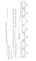
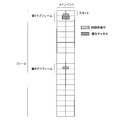
図6を用いて、1つのメインバンドの1フレームにおける報知チャネルの送信方法の一例を説明する。基地局105が送信する各種の送信信号は、メインバンド内の中心部の複数のサブキャリアを用いて送信される。1フレーム中では、報知チャネルが1回送信され、フレームの先頭を検出するための同期用信号が2回送信される。報知チャネルが送信されるタイミングは、第1サブフレームの2番目のスロットである。また、同期用信号が送信されるタイミングは、第1サブフレームの1番目のスロット及び第6サブフレームの1番目のスロットである。
また、本実施形態では、同期用信号の送信に用いられるサブキャリア数は、報知チャネルの送信に用いられるサブキャリア数より少ないものとした。
図7を用いて、第1サブフレームにおける報知チャネルと同期用信号との配置例の詳細を説明する。図4で説明したように、1つのサブフレームは14個のOFDMシンボルを含む。同期用信号は、6番目及び7番目のOFDMシンボルにおいて送信される。また、報知チャネルは、7~10番目のOFDMシンボルにて送信される。
また、前述のとおり、同期用信号や報知チャネルは、メインバンドの中心部の複数のサブキャリアを用いて送信される。端末は、メインバンドの中心部分の、同期用信号や報知チャネルの帯域幅分だけを受信すれば、フレームへの同期や、報知データの取得を行うことができる。
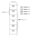
図8を用いて、1つのメインバンドにおける第1~第4報知チャネルの送信順序について説明する。単一バンド端末が報知データを受信できるように、1つのメインバンドの中で第1~第4報知チャネルの全てが送信されるようにする。また、第1~第4報知チャネルの送信順序が変わってしまうと、端末はその順番を検出しなければならなくなる。このような処理は避けたいため、図8に示すように、第1~第4報知チャネルは、この順番を保ったまま繰り返し送信される。
単一バンド端末である端末101は、必ずしも第1報知チャネルから受信し始めるわけではなく、第1~第4報知チャネルの途中から受信し始める場合もある。例えば受信を開始したタイミングが第2報知チャネルの場合がある。このような場合でも、4フレーム受信することにより、4つの報知チャネルを受信できる。
但し、この場合、端末101は、第2報知チャネル、第3報知チャネル、第4報知チャネル、第1報知チャネルの順に受信することから、4つの報知チャネルの順番を並べ替えなければならない。端末101は、この段階では報知チャネルフレームの境界を把握していないため、最初に受信した報知チャネルが何番目の報知チャネルであるかはわからない。
そこで端末101は、最初に受信した報知チャネルが、第1報知チャネルである場合、第2報知チャネルである場合、第3報知チャネルである場合、第4報知チャネルである場合の4通りのパターン(並び順)を仮定し、各パターンで復調を試みる。そして、端末101は、正しく復調できる順序を検出し、報知データを得る。そして、この正しく受信できる順序が明らかとなることで、第1報知チャネルが送信された時刻を特定することができる。
例えば図8に示す例では、第kフレームにおいて第1報知チャネルが送信され、この第kフレームの開始時刻が、報知チャネルフレームの境界であることを検出できる。
図9は、図6に示す1メインバンドの報知チャネル及び同期用信号の配置を、図3に示すような複数のメインバンドに適用した場合の、基地局105からの送信信号の構成例を示す。図9に示すように、全てのメインバンドにおいて同期チャネルと報知チャネルを送信することで、単一バンド端末は、どのメインバンドを受信しても、報知チャネルを得ることができる。
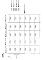
図10を用いて、図3に示すような複数メインバンドの各々における第1~第4報知チャネルの送信順序について説明する。ここではメインバンドは第1~第5メインバンドの5つのメインバンドが存在するとする。図10に示すように、同一フレームでは、第nメインバンド(nは1以上の整数)にて第1報知チャネルが送信されている時、第n+1メインバンドでは第2報知チャネルが送信され、第n+2メインバンドでは第3報知チャネルが送信される。
つまり、同一フレームにおいて、隣接するメインバンドでは異なる報知チャネルが送信され、報知チャネルの周波数方向の並び順は、第1報知チャネル、第2報知チャネル、第3報知チャネル、第4報知チャネル、第1報知チャネル、・・・となっている。また、各メインバンドの時間方向(フレーム方向)においては、第1~第4報知チャネルが、この順番を保ったまま繰り返し送信される。
このような順序で報知チャネルを送信すると、複数バンド端末である端末104が4つ以上のメインバンドを受信する機能を有する場合、1フレームで、第1~第4報知チャネルの全てを受信し、報知データを取得することができる。従って短時間で報知データを得ることができる。
また、どのメインバンドにおいても図8に示すような信号が送信されている。従って、単一バンド端末である端末101~103は、構成の変更なく、図8に示すような信号を受信する方法と同様の方法で報知データを取得できる。
端末104は、報知チャネルフレーム内の何番目のフレームを受信しているか認識していない場合、1フレーム中に含まれる複数の報知チャネルから報知データを取り出すためには、複数の報知チャネルの並び方を仮定して復調し、正しく復調できたものを探さなければならない。しかし、この処理により1フレーム内の報知チャネルの配置状況を把握できれば、報知チャネルフレームの中の何番目のフレームを受信しているかを知ることができる。
例えば、端末104は、あるフレームの第1メインバンドにおいて送信されている報知チャネルが第2報知チャネルであることがわかれば、この1つ前のフレームにおいて第1報知チャネルが送信されていると判断でき、そこが報知チャネルフレームの境界であると検出できる。
このように、1フレームのみを受信し、報知チャネルが送信されるパターンを知ることによって、報知チャネルフレームの境界を検出できる。
なお、端末104が3つのメインバンドを受信する機能を有する場合は、報知チャネル送信パターンを把握し報知チャネルフレームの境界を検出するのに2フレームを要する。また、端末104が2つのメインバンドを受信する機能を有する場合は、報知チャネル送信パターンを把握し報知チャネルフレームの境界を検出するのに3フレームを要する。
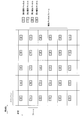
図11に、比較例による複数メインバンドの各々における第1~第4報知チャネルの送信順序について説明する。第1報知チャネルから第4報知チャネルは、前述の通り、この順番のまま、時間方向に連続した4つのフレームにおいて送信される。また、同一フレーム内の各メインバンドにて、同一の報知チャネルが送信される。
例えば、図11における第kフレームでは、全てのメインバンドにおいて第1報知チャネルが送信される。このような送信順序の報知チャネルを複数バンド端末が受信する場合、単一バンド端末と同様に、4つの連続したフレームを受信しないと、第1~第4報知チャネルを得ることができない。即ち、報知データを得るためには、最低でも4フレームを受信しなければならないことになる。従って、複数バンド端末のスループットが低下する。
一方、本実施形態では、図10に示すように、同一フレーム内の互いに隣接するメインバンドにおいて異なる報知チャネルを送信することで、複数バンド端末が報知データを得るために必要な受信フレーム数を4未満にすることができ、スループット低下を防止できる。また、どのメインバンドでも第1~第4報知チャネルが、この順番を保ったまま繰り返し送信されるため、単一バンド端末は報知データを正しく受信できる。
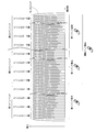
図12に、上記のような順序で報知チャネルを送信できる送信機(基地局105)の概略構成を示す。基地局105は、データ生成部111、データ分割部112、サイクリックシフト制御部113、第1~第5サイクリックシフト部114~118、同期信号生成部119、データ配置部120、逆フーリエ変換部121、送信RF部122、及び送信アンテナ108を有する。
データ生成部111は、送信する報知データを生成する。この報知データには、基地局105のID、メインバンドの帯域幅、送信時のアンテナ数、送信フレーム番号などの情報が含まれる。データ生成部111は、報知データに対し、誤り訂正符号化、誤り検出符号の付与、及び変調を施し、データ分割部112へ出力する。
データ分割部112は、データ生成部111により生成された報知データを4つに分割し、4つの報知チャネル(第1~第4報知チャネル)を生成する。データ分割部112は、生成した4つの報知チャネル全てを、第1~第5サイクリックシフト部114~118の各々へ出力する。
第1サイクリックシフト部114は、データ分割部112により生成された4つの報知チャネルに対し、サイクリックシフトを施す。例えばサイクリックシフト量が1の場合、第1サイクリックシフト部114は、報知チャネルフレーム内にて、第2報知チャネル、第3報知チャネル、第4報知チャネル、第1報知チャネルの順で出力を行う。サイクリックシフト量は、後述するサイクリックシフト制御部113から与えられる。
第2~第5サイクリックシフト部115~118は、第1サイクリックシフト部114と同様に動作する。但し、サイクリックシフト量は、後述するサイクリックシフト制御部113から与えられたものを用いるため、全てが同じ量だけサイクリックシフトするわけではない。
サイクリックシフト制御部113は、第1~第5サイクリックシフト部114~118の各々に対応するサイクリックシフト量を生成して出力する。例えば、サイクリックシフト制御部113は、図10に示すような報知チャネルの配置を実現するために、第1~第5サイクリックシフト部114~118に対しそれぞれ、0、1、2、3、0のサイクリックシフト量を与える。
同期信号生成部119は、同期用信号を生成し、データ配置部120へ出力する。
データ配置部120は、第1~第5サイクリックシフト部114~118から出力された報知チャネルと、同期信号生成部119から出力された同期用信号を、サブキャリアに配置する。例えば、第1サイクリックシフト部114から出力された報知チャネルは、第1メインバンドの中心に位置する、予め決められた複数のサブキャリアに配置される。
第2~第5サイクリックシフト部115~118から出力される報知チャネルも同様に、第2~第5メインバンドに配置される。各報知チャネルは、フレーム内の第1サブフレームの、後半のスロットの、先頭4OFDMシンボルへと配置される。
また、同期用信号も、報知チャネルと同様に各メインバンドの中心に配置される。同期用信号は、図6、図7に示すように、フレーム内の第1サブフレーム及び第6サブフレームの、前半のスロットの、後半2OFDMシンボルへと配置される。
データ配置部120により報知チャネル及び同期用信号が配置されたサブキャリアは、逆フーリエ変換部121へ出力される。
逆フーリエ変換部121は、サブキャリアを逆フーリエ変換し、サイクリックプレフィックスを付与する。
送信RF部122は、逆フーリエ変換部121の出力信号を送信RF信号に変換し、送信アンテナ108から送信する。
図13に、受信機(端末101~104)の概略構成を示す。受信機は、受信アンテナ109、受信RF部131、フレーム同期部132、フーリエ変換部133、データ抽出部134、及びデータ復調部135を有する。
受信RF部131は、受信アンテナ109を介して受信した受信RF信号をベースバンド信号へと変換し、フレーム同期部132及びフーリエ変換部133へ出力する。
フレーム同期部132は、受信ベースバンド信号に含まれる同期用信号を検出してフレームの境界を把握する。フレームの境界を把握することで、OFDMシンボルの位置を決めることができる。フレーム同期部132は、検出したフレーム境界の位置をフーリエ変換部133へ通知する。
フーリエ変換部133は、受信ベースバンド信号から、フレーム同期部132の通知に基づきOFDMシンボルを切り出し、さらにサイクリックプレフィックスを取り除く。そして、フーリエ変換部133は、フーリエ変換処理により、サブキャリアへの変換を行う。フーリエ変換部133によって受信ベースバンド信号から生成されたサブキャリアは、データ抽出部134へ出力される。
データ抽出部134は、サブキャリアの中から、報知チャネルを取り出し、データ復調部135へ出力する。
データ復調部135は、データ抽出部134から与えられた報知チャネルを連結することで報知データを得て、復調、誤り訂正処理を行うことで、情報を取り出す。このとき、受信機が単一バンド端末であれば、データ復調部134は、連続する4フレーム分の報知チャネルを用いて復調を行う。前述の通り、第1~第4報知チャネルが順に入力されるものの、先頭が第1報知チャネルでない場合があるので、最大4通りの復調を試し、誤り検出符号の検査を通じて復調に成功するものを探す。
受信機が複数バンド端末の場合は、受信できるメインバンド数に応じて1~3フレーム内に含まれる報知チャネルを用いて復調処理を行う。
データ復調部135は、復調に成功した報知チャネルのパターン(順番)から、報知チャネルフレームの境界(報知チャネルフレームの開始(終了)タイミング)を検出することができる。この報知チャネルフレームの境界に基づき、端末101~104と基地局105との同期が確立し、以降のデータ通信が可能となる。
図12に示す送信機(基地局105)による報知チャネルの送信方法を、図14に示すフローチャートを用いて説明する。
(ステップS1401)同期信号生成部119が、送信処理開始に伴い、送受信機間で予め取り決められた同期用信号を生成する。
(ステップS1402)データ生成部111が、報知データとして送信する情報、即ち基地局105のID番号やメインバンドの帯域幅等を生成する。
(ステップS1403)データ生成部111が、前記情報の誤り訂正符号化を行う。
(ステップS1404)データ生成部111が、前記情報に誤り検出符号を付与する。
(ステップS1405)データ生成部111が、前記情報に変調を施し、報知データを生成する。
(ステップS1406)データ分割部112が、報知データを4分割して、第1~第4報知チャネルを生成する。
ステップS1402~S1406における報知チャネルを生成する処理は、必ずしも送信処理の度に実施する必要は無く、前回の送信処理から報知データに変更が無ければ、前回の報知チャネルを再利用しても良い。
(ステップS1407)サイクリックシフト制御部113が、第1~第5メインバンドにおけるサイクリックシフト量C1~C5を決定する。
例えば、図10に示すような報知チャネルの配置を行う場合、サイクリックシフト量C1~C5は、0、1、2、3、0となる。つまり、サイクリックシフト量C1とC2の差分、サイクリックシフト量C2とC3の差分、サイクリックシフト量C3とC4の差分がそれぞれ等しくなる。また、サイクリックシフト量C4とC5の差分も等しい。報知チャネルが4つある場合、サイクリックシフト量の0と4は同じであるためである。
(ステップS1408)第1サイクリックシフト部114が、第1メインバンドで送信する4つの報知チャネルをC1だけサイクリックシフトする。
(ステップS1409)第2サイクリックシフト部115が、第2メインバンドで送信する4つの報知チャネルをC2だけサイクリックシフトする。
例えばC2が1の場合、第2サイクリックシフト部115は、4つの報知チャネルを第2、第3、第4、第1報知チャネルの順に並べ替える。
(ステップS1410)第3サイクリックシフト部116が、第3メインバンドで送信する4つの報知チャネルをC3だけサイクリックシフトする。
(ステップS1411)第4サイクリックシフト部117が、第4メインバンドで送信する4つの報知チャネルをC4だけサイクリックシフトする。
(ステップS1412)第5サイクリックシフト部118が、第5メインバンドで送信する4つの報知チャネルをC5だけサイクリックシフトする。
例えばC5が0の場合、第5サイクリックシフト部118はサイクリックシフトを施さず、4つの報知チャネルの順番は第1、第2、第3、第4報知チャネルのままである。
(ステップS1413)サイクリックシフト部114~118から1番目に出力される報知チャネルと、同期信号生成部119により生成される同期用信号とがデータ配置部120によりサブキャリアに配置され、逆フーリエ変換部121、送信RF部122、送信アンテナ108を介して第kフレームにて送信される。
(ステップS1414)サイクリックシフト部114~118から2番目に出力される報知チャネルと、同期信号生成部119により生成される同期用信号とがデータ配置部120によりサブキャリアに配置され、逆フーリエ変換部121、送信RF部122、送信アンテナ108を介して第k+1フレームにて送信される。
(ステップS1415)サイクリックシフト部114~118から3番目に出力される報知チャネルと、同期信号生成部119により生成される同期用信号とがデータ配置部120によりサブキャリアに配置され、逆フーリエ変換部121、送信RF部122、送信アンテナ108を介して第k+2フレームにて送信される。
(ステップS1416)サイクリックシフト部114~118から4番目に出力される報知チャネルと、同期信号生成部119により生成される同期用信号とがデータ配置部120によりサブキャリアに配置され、逆フーリエ変換部121、送信RF部122、送信アンテナ108を介して第k+3フレームにて送信される。
ステップS1413~S1416が繰り返されることで、図10に示すような順序で報知チャネルが送信される。
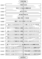
図13に示す受信機による報知チャネルの受信方法を、図15に示すフローチャートを用いて説明する。ここで受信機は5つのメインバンドを受信する機能を有する複数バンド端末であるとする。
(ステップS1501)受信RF部131が、受信処理の開始に伴い、受信アンテナ109を介して受信した受信RF信号を、受信ベースバンド信号に変換する。
(ステップS1502)フレーム同期部132が、受信ベースバンド信号中の同期用信号を用いて、フレーム同期を確立する。フレーム同期部132が同期用信号を検出できない場合、受信機は信号が送られていないとみなす。同期用信号が検出され、フレーム同期を確立できた場合は、基地局105が信号を送信しているとみなす。
但し、この時点では、受信機は、どのメインバンドを受信しているかわからない。また、この時点で受信機は、フレーム間の境界を知ることができるものの、報知チャネルフレームの境界は特定していない。
(ステップS1503)フーリエ変換部133が、フレーム境界に基づき、検出した同期チャネルに対応する周波数を中心とする5メインバンドの信号を1フレーム分だけ受信する。
(ステップS1504)フーリエ変換部133が、5メインバンドの信号を切り出し、フーリエ変換してサブキャリアを取り出す。この時点で受信機は未だどのメインバンドを受信しているかは判らないので、報知チャネルの有無に関わらず、データ抽出部134が、フーリエ変換された5メインバンド分の信号のうち、報知チャネルに該当する部分から変調シンボルを取り出す。
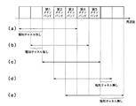
例えば、図16(a)に示すように、フレーム同期部132が第1メインバンドの同期用信号を検出していた場合、フーリエ変換部133でフーリエ変換された5メインバンドのうち、周波数の低い2メインバンド分には報知チャネルは含まれていない。一方、周波数の高い3メインバンド分、すなわち第1~第3メインバンドの報知チャネルは含まれている。
同様に、フレーム同期部132が第2メインバンドの同期用信号を検出していた場合、図16(b)に示すように、フーリエ変換部133でフーリエ変換された5メインバンドのうち、最も周波数の低い1メインバンドには報知チャネルは含まれていない。一方、周波数の高い4メインバンド分、すなわち第1~第4メインバンドの報知チャネルは含まれている。
同様に、フレーム同期部132が第3メインバンドの同期用信号を検出していた場合、図16(c)に示すように、フーリエ変換部133でフーリエ変換された5メインバンドには第1~第5メインバンドすべての報知チャネルが含まれる。
同様に、フレーム同期部132が第4メインバンドの同期用信号を検出していた場合、図16(d)に示すように、フーリエ変換部133でフーリエ変換された5メインバンドのうち、最も周波数の高い1メインバンドには報知チャネルは含まれていない。一方、周波数の低い4メインバンド分、すなわち第2~第5メインバンドの報知チャネルは含まれている。
同様に、フレーム同期部132が第5メインバンドの同期用信号を検出していた場合、図16(e)に示すように、フーリエ変換部133でフーリエ変換された5メインバンドのうち、周波数の高い2メインバンドには報知チャネルは含まれていない。一方、周波数の低い3メインバンド分、すなわち第3~第5メインバンドの報知チャネルは含まれている。
(ステップS1505)データ復調部135が、報知チャネルの復調を行う。但し、この時点ではステップS1504で抽出された報知チャネルがどのように並んでいるか不明である。そのため、ステップS1502で同期用信号が受信されたメインバンドの番号R、及びステップS1504でフーリエ変換したフレームの番号Sを仮定する。
例えば、ステップS1502で同期用信号が受信されたメインバンドが第1メインバンドであり、ステップS1504でフーリエ変換したフレームが、報知チャネルフレーム中の先頭フレームであったと仮定する場合、R=1、S=1となる。この時、図10に示すような信号配置で報知チャネルが送信されているとすれば、フーリエ変換後の中心メインバンドで第1報知チャネル、1つ周波数の高い側のメインバンドで第2報知チャネル、そして最も周波数が高いメインバンドで第3報知チャネルが送信されているはずである。
(ステップS1506)仮定した報知チャネルの並びに基づいて復調を行う。ここで、上述の仮定では、第4報知チャネルは受信していないことになるので、復調の際に0をセットする。伝送路の状況によっては、報知チャネル1つ分が0であっても、誤り訂正符号により正しく情報を得られる可能性がある。
(ステップS1507)データ復調部135が、誤り検出符号をチェックする。チェック結果が正しい場合はステップS1514へ進み、誤りの場合はステップS1508へ進む。
(ステップS1508)Rをインクリメントする(1を足す)。
(ステップS1509)Rが5以下の場合はステップS1506に戻り、5を超えた場合はステップS1510へ進む。
(ステップS1510)Rを0に戻し、Sをインクリメントする(1を足す)。
(ステップS1511)Sが4以下の場合はステップS1506に戻り、4を超えた場合はステップS1512へ進む。
(ステップS1512)受信したフレーム数が4つの場合はステップS1515へ進む。4つ未満の場合はステップS1513へ進む。
(ステップS1513)5メインバンドの信号を新たに1フレーム分だけ受信し、ステップS1505に戻る。
これにより復調に利用できる報知チャネルの数が増す。例えばR=0、S=0が真であったが、正しく復調できなかった場合、新たに次の1フレームを受信することで、復調に利用できる報知チャネルが、それまでの第1、第2、第3報知チャネルに加え、新たに第2、第3、第4報知チャネルが加わる。
従って第2、第3報知チャネルについては信号を加算することで、信号の信頼性を向上させ、新たに加わった第4報知チャネルも利用して復調することで、高い確率で報知データを正確に復調できるようになる。
(ステップS1514)報知データによって伝送された情報が取得される。また、ステップS1506で復調した時のR、Sの仮定が正しいため、受信したメインバンドの番号と、報知チャネルフレーム中のフレーム番号を得ることができる。
(ステップS1515)報知チャネルは含まれていないと判断し、処理を終了する。
このように、R=0からR=5まで、及びS=1からS=4までの復調を繰り返し、正しく復調できるR、Sを検出する。そして、報知データにより送られた情報を取得し、受信したメインバンド及び報知チャネルフレームの境界を特定できる。
図10に示すような配置で報知チャネルを送信することで、複数バンド端末は報知データの取得及び報知チャネルフレームの境界の特定を3フレーム以下の時間で行うことができる。図11に示すような配置で報知チャネルを送信すると、少なくとも4フレームの時間を要するため、受信処理時間を短縮できる。また、単一バンド端末は、どのメインバンドを受信しても、報知データの取得及び報知チャネルフレームの境界の特定を正しく行うことができる。
このように、本実施形態により、複数バンド端末のスループット低下を防止し、かつ単一バンド端末に正しくデータ受信させることができる。
図10に示す例では、同一フレームで送信される報知チャネルをメインバンド方向に第1報知チャネル、第2報知チャネル、第3報知チャネル、第4報知チャネル、第1報知チャネル、・・・としたが、図17に示すように、第4報知チャネル、第3報知チャネル、第2報知チャネル、第1報知チャネル、第4報知チャネル、・・・としてもよい。
また、図18に示すように、同一フレームで送信される報知チャネルをメインバンド方向に第1報知チャネル、第3報知チャネル、第2報知チャネル、第4報知チャネル、第1報知チャネル、・・・としてもよい。
つまり、同一フレームの第nメインバンドにおいて送信される報知チャネルと第n+1メインバンドにおいて送信される報知チャネルの間隔と、第n+1メインバンドにおいて送信される報知チャネルと第n+2メインバンドにおいて送信される報知チャネルの間隔とが異なるように報知チャネルが配置される。
例えば第kフレームでは、第1メインバンドで第1報知チャネルが送信され、第2メインバンドで第3報知チャネルが送信されるため、間隔は“+2”となる。また、第2メインバンドで第3報知チャネルが送信され、第3メインバンドで第2報知チャネルが送信されるため、間隔は“-1”となる。なお、報知データが第1~第4報知チャネルに分割されている場合は、間隔“-1”は間隔“+3”と同じである。
このような報知チャネルの配置は、以下の理由で報知チャネルフレームの境界特定やメインバンドの認識という点で優れている。
メインバンド方向に並んでいる3つの報知チャネルのパターン(並び方)に着目すると、5つのメインバンド及び1つの報知チャネルフレームの中で、同一のパターンが複数現れない。例えば第kフレームの第1~第3メインバンドに配置されている報知チャネルのパターン、即ち第1、第3、第2報知チャネルというパターンは、同一報知チャネルフレーム内のいずれの場所にも現れない。
従って、メインバンド方向に第1、第3、第2報知チャネルが並んでいることを検出した複数バンド端末は、そこが第1~第3メインバンドであり、かつ報知チャネルフレームの中では先頭のフレームであることを速やかに認識できる。
このような報知チャネルの配置は、サイクリックシフト制御部113が、サイクリックシフト量C1~C5を、0、2、1、3、0とすることで実現できる。シフト量C1とC2の差分が、シフト量C2とC3の差分と異なる。同様に、シフト量C2とC3の差分が、シフト量C3とC4の差分と異なる。
上記実施形態では、報知データを4つの報知チャネルに分割する例について説明したが、分割数は4以外でもよい。
上述した実施形態で説明した端末、基地局の少なくとも一部は、ハードウェアで構成してもよいし、ソフトウェアで構成してもよい。ソフトウェアで構成する場合には、端末、基地局の少なくとも一部の機能を実現するプログラムをフレキシブルディスクやCD-ROM等の記録媒体に収納し、コンピュータに読み込ませて実行させてもよい。記録媒体は、磁気ディスクや光ディスク等の着脱可能なものに限定されず、ハードディスク装置やメモリなどの固定型の記録媒体でもよい。
なお、本発明は上記実施形態そのままに限定されるものではなく、実施段階ではその要旨を逸脱しない範囲で構成要素を変形して具体化できる。また、上記実施形態に開示されている複数の構成要素の適宜な組み合わせにより、種々の発明を形成できる。例えば、実施形態に示される全構成要素から幾つかの構成要素を削除してもよい。さらに、異なる実施形態にわたる構成要素を適宜組み合わせてもよい。
101~104 端末
105 基地局
106 下りリンク
107 上りリンク
108、109 アンテナ
111 データ生成部
112 データ分割部
113 サイクリックシフト制御部
114~118 サイクリックシフト部
119 同期信号生成部
120 データ配置部
121 逆フーリエ変換部
122 送信RF部
131 受信RF部
132 フレーム同期部
133 フーリエ変換部
134 データ抽出部
135 データ復調部
105 基地局
106 下りリンク
107 上りリンク
108、109 アンテナ
111 データ生成部
112 データ分割部
113 サイクリックシフト制御部
114~118 サイクリックシフト部
119 同期信号生成部
120 データ配置部
121 逆フーリエ変換部
122 送信RF部
131 受信RF部
132 フレーム同期部
133 フーリエ変換部
134 データ抽出部
135 データ復調部
Claims (6)
- 第1~第n(nは2以上の整数)のメインバンドを介して通信する無線通信装置であって、
報知データを生成するデータ生成部と、
前記報知データをm個(mは2以上の整数)の報知チャネルに分割する分割部と、
前記第1~第nのメインバンドで送信する信号に施す第1~第nのシフト量を生成する制御部と、
第k(kは1≦k≦nを満たす整数)のシフト量に従って定められる、第kのメインバンドで前記m個の報知チャネルを送信する順序で、前記m個の報知チャネルを出力する第kのシフト部と、
前記第kのシフト部から出力される報知チャネルを、前記第kのメインバンド内のサブキャリアに配置する配置部と、
前記報知チャネルが配置された前記第1~第nのメインバンド内のサブキャリアを送信RF信号に変換して送信する送信部と、
を備える無線通信装置。 - 前記第kのシフト部は、第j(jは1≦j≦m-1を満たす整数)の報知チャネルと第j+1の報知チャネルが連続し、第mの報知チャネルと第1の報知チャネルが連続するような順序で前記報知チャネルを出力することを特徴とする請求項1に記載の無線通信装置。
- 前記制御部は、前記第1のシフト量と前記第2のシフト量との差分が、前記第2のシフト量と前記第3のシフト量の差分と等しくなるように、前記シフト量を生成することを特徴とする請求項1に記載の無線通信装置。
- 前記制御部は、前記第1のシフト量と前記第2のシフト量との差分が、前記第2のシフト量と前記第3のシフト量の差分と異なるように、前記シフト量を生成することを特徴とする請求項1に記載の無線通信装置。
- 前記第1~第nのメインバンドは連続する周波数帯域であることを特徴とする請求項1に記載の無線通信装置。
- 複数のメインバンドの各々に、報知データを分割した複数の報知チャネルのいずれかが互いに異なるように配置された信号を受信する受信部と、
前記複数のメインバンドの各々から、前記報知チャネルを抽出する抽出部と、
前記抽出された報知チャネルを連結し、前記報知データを取得する復調部と、
を備える無線通信装置。
Priority Applications (1)
| Application Number | Priority Date | Filing Date | Title |
|---|---|---|---|
| US13/189,917 US8824393B2 (en) | 2009-01-29 | 2011-07-25 | Wireless communication device |
Applications Claiming Priority (2)
| Application Number | Priority Date | Filing Date | Title |
|---|---|---|---|
| JP2009017874A JP5112353B2 (ja) | 2009-01-29 | 2009-01-29 | 無線通信装置及び無線通信方法 |
| JP2009-017874 | 2009-01-29 |
Related Child Applications (1)
| Application Number | Title | Priority Date | Filing Date |
|---|---|---|---|
| US13/189,917 Continuation US8824393B2 (en) | 2009-01-29 | 2011-07-25 | Wireless communication device |
Publications (1)
| Publication Number | Publication Date |
|---|---|
| WO2010087331A1 true WO2010087331A1 (ja) | 2010-08-05 |
Family
ID=42395592
Family Applications (1)
| Application Number | Title | Priority Date | Filing Date |
|---|---|---|---|
| PCT/JP2010/050964 Ceased WO2010087331A1 (ja) | 2009-01-29 | 2010-01-26 | 無線通信装置 |
Country Status (3)
| Country | Link |
|---|---|
| US (1) | US8824393B2 (ja) |
| JP (1) | JP5112353B2 (ja) |
| WO (1) | WO2010087331A1 (ja) |
Cited By (1)
| Publication number | Priority date | Publication date | Assignee | Title |
|---|---|---|---|---|
| WO2013003648A1 (en) * | 2011-06-29 | 2013-01-03 | Qualcomm Incorporated | Methods and apparatus by which periodically broadcasting nodes can resolve contention for access to a smaller pool of broadcasting resources |
Families Citing this family (3)
| Publication number | Priority date | Publication date | Assignee | Title |
|---|---|---|---|---|
| JP5091895B2 (ja) | 2009-03-13 | 2012-12-05 | 株式会社東芝 | 送信装置、および受信装置 |
| KR101953216B1 (ko) * | 2011-11-11 | 2019-02-28 | 삼성전자주식회사 | 이동 통신 시스템에서 시스템 정보 전송 방법 및 장치 |
| CN109756231B (zh) * | 2018-12-27 | 2023-01-31 | 北京思朗科技有限责任公司 | 循环移位处理装置及方法 |
Citations (2)
| Publication number | Priority date | Publication date | Assignee | Title |
|---|---|---|---|---|
| WO2007080892A1 (ja) * | 2006-01-11 | 2007-07-19 | Matsushita Electric Industrial Co., Ltd. | 無線通信基地局装置および報知チャネル信号の送信帯域設定方法 |
| WO2008004681A1 (en) * | 2006-07-03 | 2008-01-10 | Nec Corporation | Broadcast channel transmission method and apparatus |
Family Cites Families (5)
| Publication number | Priority date | Publication date | Assignee | Title |
|---|---|---|---|---|
| JP4515155B2 (ja) * | 2004-05-25 | 2010-07-28 | 株式会社エヌ・ティ・ティ・ドコモ | 送信装置 |
| JP4781116B2 (ja) * | 2005-06-30 | 2011-09-28 | 三洋電機株式会社 | 無線装置 |
| JP4808104B2 (ja) * | 2006-08-21 | 2011-11-02 | 株式会社エヌ・ティ・ティ・ドコモ | 基地局装置及び報知情報送信方法 |
| JP2008211657A (ja) * | 2007-02-27 | 2008-09-11 | Kyocera Corp | 無線通信方法及び無線通信システム |
| KR101307123B1 (ko) * | 2007-05-04 | 2013-09-10 | 삼성전자주식회사 | 직교 주파수 분할 다중 접속 시스템에서의 데이터 송수신방법 및 장치 |
-
2009
- 2009-01-29 JP JP2009017874A patent/JP5112353B2/ja not_active Expired - Fee Related
-
2010
- 2010-01-26 WO PCT/JP2010/050964 patent/WO2010087331A1/ja not_active Ceased
-
2011
- 2011-07-25 US US13/189,917 patent/US8824393B2/en not_active Expired - Fee Related
Patent Citations (2)
| Publication number | Priority date | Publication date | Assignee | Title |
|---|---|---|---|---|
| WO2007080892A1 (ja) * | 2006-01-11 | 2007-07-19 | Matsushita Electric Industrial Co., Ltd. | 無線通信基地局装置および報知チャネル信号の送信帯域設定方法 |
| WO2008004681A1 (en) * | 2006-07-03 | 2008-01-10 | Nec Corporation | Broadcast channel transmission method and apparatus |
Cited By (4)
| Publication number | Priority date | Publication date | Assignee | Title |
|---|---|---|---|---|
| WO2013003648A1 (en) * | 2011-06-29 | 2013-01-03 | Qualcomm Incorporated | Methods and apparatus by which periodically broadcasting nodes can resolve contention for access to a smaller pool of broadcasting resources |
| CN103650607A (zh) * | 2011-06-29 | 2014-03-19 | 高通股份有限公司 | 周期性广播节点能用于解决对较小广播资源池的访问争用的方法和装置 |
| US8798656B2 (en) | 2011-06-29 | 2014-08-05 | Qualcomm Incorporated | Methods and apparatus by which periodically broadcasting nodes can resolve contention for access to a smaller pool of broadcasting resources |
| CN103650607B (zh) * | 2011-06-29 | 2017-05-31 | 高通股份有限公司 | 周期性广播节点能用于解决对较小广播资源池的访问争用的方法和装置 |
Also Published As
| Publication number | Publication date |
|---|---|
| US20110280190A1 (en) | 2011-11-17 |
| US8824393B2 (en) | 2014-09-02 |
| JP2010178016A (ja) | 2010-08-12 |
| JP5112353B2 (ja) | 2013-01-09 |
Similar Documents
| Publication | Publication Date | Title |
|---|---|---|
| US11277871B2 (en) | Initial access channel for scalable wireless mobile communication networks | |
| CN101599795B (zh) | 用于多载波系统的新型帧结构 | |
| US9565001B2 (en) | Guard subcarrier placement in an OFDM symbol used for synchronization | |
| US10044421B2 (en) | Wireless communication via combined channel training and physical layer header signaling | |
| CN110582979B (zh) | 通信装置、基础设施设备和方法 | |
| RU2341897C1 (ru) | Улучшенные способ и устройство передачи сигналов маяка | |
| CN111147213B (zh) | 一种信号的发送方法及终端 | |
| EP3759881B1 (en) | Application of asynchronous coded multiple access in a system employing orthogonal frequency division multiplexing | |
| CN101599944A (zh) | 用于多载波系统的新型帧结构 | |
| WO2019008888A1 (ja) | 通信装置及び通信方法 | |
| JP5112353B2 (ja) | 無線通信装置及び無線通信方法 | |
| US9173195B2 (en) | Method and apparatus for transmitting/receiving control information in broadcast communication system | |
| US8824407B2 (en) | Systems and methods for network entry management | |
| CN101099361B (zh) | 在ofdm移动通信系统内实现时间同步的方法 | |
| JP5045127B2 (ja) | 無線通信システム | |
| KR20080028090A (ko) | 무선통신시스템에서 스케줄링 채널 신호의 송수신 방법 및 장치 | |
| EP2583405B1 (en) | Control channel architecture with control information distributed over multiple subframes | |
| WO2016015782A1 (en) | Sub-band allocation signaling in a non-contiguous multi-carrier communication system | |
| JP7012460B2 (ja) | 基地局、端末、無線通信システムおよび通信方法 |
Legal Events
| Date | Code | Title | Description |
|---|---|---|---|
| 121 | Ep: the epo has been informed by wipo that ep was designated in this application |
Ref document number: 10735799 Country of ref document: EP Kind code of ref document: A1 |
|
| NENP | Non-entry into the national phase |
Ref country code: DE |
|
| 122 | Ep: pct application non-entry in european phase |
Ref document number: 10735799 Country of ref document: EP Kind code of ref document: A1 |