WO2010087214A1 - 基地局装置、移動局装置および移動通信システム - Google Patents
基地局装置、移動局装置および移動通信システム Download PDFInfo
- Publication number
- WO2010087214A1 WO2010087214A1 PCT/JP2010/050070 JP2010050070W WO2010087214A1 WO 2010087214 A1 WO2010087214 A1 WO 2010087214A1 JP 2010050070 W JP2010050070 W JP 2010050070W WO 2010087214 A1 WO2010087214 A1 WO 2010087214A1
- Authority
- WO
- WIPO (PCT)
- Prior art keywords
- phase rotation
- station apparatus
- base station
- physical cell
- unit
- Prior art date
- Legal status (The legal status is an assumption and is not a legal conclusion. Google has not performed a legal analysis and makes no representation as to the accuracy of the status listed.)
- Ceased
Links
Images


Classifications
-
- H—ELECTRICITY
- H04—ELECTRIC COMMUNICATION TECHNIQUE
- H04L—TRANSMISSION OF DIGITAL INFORMATION, e.g. TELEGRAPHIC COMMUNICATION
- H04L5/00—Arrangements affording multiple use of the transmission path
- H04L5/0001—Arrangements for dividing the transmission path
- H04L5/0003—Two-dimensional division
- H04L5/0005—Time-frequency
- H04L5/0007—Time-frequency the frequencies being orthogonal, e.g. OFDM(A) or DMT
- H04L5/001—Time-frequency the frequencies being orthogonal, e.g. OFDM(A) or DMT the frequencies being arranged in component carriers
-
- H—ELECTRICITY
- H04—ELECTRIC COMMUNICATION TECHNIQUE
- H04L—TRANSMISSION OF DIGITAL INFORMATION, e.g. TELEGRAPHIC COMMUNICATION
- H04L27/00—Modulated-carrier systems
- H04L27/26—Systems using multi-frequency codes
- H04L27/2601—Multicarrier modulation systems
- H04L27/2614—Peak power aspects
- H04L27/2621—Reduction thereof using phase offsets between subcarriers
Definitions
- the present invention relates to a base station apparatus, a mobile station apparatus, and a mobile communication system that perform wireless communication using a multicarrier communication system.
- 3G third generation
- EUTRA Evolved® Universal® Terrestrial® Radio Access
- EUTRAN Evolution
- 3GPP 3rd Generation Partnership Project
- A-EUTRA 4th generation radio access scheme
- A-EUTRAN Advanced EUTRAN
- component carrier the frequency band of A-EUTRA is divided into a plurality of frequencies
- EUTRA has decided to adopt an OFDMA (Orthogonal-Frequency-Division-Multiple-Access) system that is resistant to multipath interference and suitable for high-speed transmission as a downlink communication system.
- OFDMA Orthogonal-Frequency-Division-Multiple-Access
- the mobile station apparatus receives signals transmitted from the base station apparatus in a cell or sector that is a communication area of the base station apparatus. Must be synchronized.
- the base station apparatus transmits a synchronization channel SCH having a prescribed configuration, obtains a correlation with the synchronization channel SCH stored in advance in the mobile station apparatus, and synchronizes with the base station apparatus by detecting the synchronization channel SCH.
- a primary synchronization channel P-SCH Primary synchronization channel
- S-SCH Secondary synchronization channel
- FIG. 6 is a diagram illustrating an example of a configuration of a radio frame in EUTRA.
- the horizontal axis represents the time axis
- the vertical axis represents the frequency axis.
- a radio frame is configured with a frequency axis as 12 subcarriers (sc) and a time axis as a unit of a slot which is a set of a plurality of OFDM symbols, and an area divided by 12 subcarriers and 1 slot length is called a resource block.
- Non-Patent Document 1 A group of two slots is called a subframe, and a group of ten subframes is called a frame.
- the # 0 and # 5 subframes include the above-described P-SCH, S-SCH, and broadcast information channel, and the mobile station apparatus determines the time between the received signal and a plurality of sequence replica signals of the primary synchronization channel P-SCH.
- Slot synchronization is established by taking correlation in the domain (step 1), and further, correlation is obtained in the time domain or frequency domain with the received signal and a plurality of replica signals of the secondary synchronization channel S-SCH.
- the frame synchronization is established by the secondary synchronization channel S-SCH sequence, and the physical cell ID (Identification: identification information) Nid (0 ⁇ Nid) for identifying the base station apparatus together with the previously detected P-SCH sequence ⁇ 503) is specified (step 2).
- the above two steps are called a cell search procedure.
- main parameters such as the number of transmission antenna ports can be acquired by demodulating the broadcast information channel.
- FIGS. 7A to 7C are diagrams showing details of one resource block.
- 7A to 7C show the positions of reference signals (also referred to as pilot signals and reference signals) of the antenna ports when the number of transmission antenna ports is 1, 2, and 4, respectively.
- the reference signal is a known signal used for demodulating the signal, and the use sequence and the arrangement pattern are uniquely specified by the physical cell ID Nid of the base station.
- FIG. 8 is an excerpt of only the arrangement of antenna port 1 with 4 antenna ports.
- the reference signal RS1 of the first antenna (Ant1) and the reference signal RS2 of the second antenna (Ant2) are the first of the resource blocks.
- the third antenna reference signal RS3 and the fourth antenna reference signal RS4 are arranged in the second OFDM symbol.
- each component carrier of A-EUTRA has the EUTRA frame structure shown in FIG. 6, the frame structure of A-EUTRA in which the component carriers are continuously arranged is as shown in FIG.
- the guard band of each component carrier is arrange
- a signal is transmitted from the A-EUTRA base station apparatus in the A-EUTRA frame configuration of FIG.
- FIG. 10 is a diagram showing a schematic configuration of an A-EUTRA base station apparatus.
- base station apparatus 1000 encoding sections 101-1 to 101-n code transmission data for each component carrier. Further, the signals encoded by the modulators 102-1 to 102-n are modulated. Further, the SCH / RS generators 103-1 to 103-n generate a synchronization channel and a reference signal based on a physical cell ID (common to all component carriers) and generation timing notified from a control unit described later.
- Multiplexers 104-1 to 104-n receive the signals modulated by modulators 102-1 to 102-n and the synchronization channels and reference signals generated by SCH / RS generators 103-1 to 103-n. Multiplex in 1 OFDM symbol unit.
- Component carrier multiplexing section 106 maps the signal for one OFDM symbol multiplexed by multiplexing sections 104-1 to 104-n for each component carrier in the frequency domain as shown in FIG.
- the frequency / time conversion unit 107 converts the frequency domain signal multiplexed by the component carrier multiplexing unit 106 into a time domain signal by IFFT calculation.
- the transmission unit 108 converts the digital signal converted into the time domain signal into an analog signal, performs power amplification on a carrier wave of a predetermined frequency, and transmits the analog signal.
- the encoding unit 101-1 to the transmission unit 108 constitute a transmission processing unit.
- the base station apparatus 1000 converts the signal received from the mobile station apparatus by the receiving unit 110 into a baseband digital signal. Further, the demodulation units 111-1 to 111-n demodulate the signals for each component carrier, and decode the signals demodulated by the decoding units 112-1 to 112-n.
- the reception unit 110 to decoding unit 112-n constitute a reception processing unit.
- the control unit 113 controls each component of the transmission processing unit and the reception processing unit.
- Upper layer 115 outputs a transmission signal to the transmission processing unit, receives the reception signal from the reception processing unit, and outputs control information to control unit 113.
- an EUTRA signal is encoded for each component carrier by coding sections 101-1 to 101-n, modulation sections 102-1 to 102-n, and SCH / RS generation sections 103-1 to 103-1. 103-n and multiplexing units 104-1 to 104-n.
- the component carrier multiplexing unit 106 bundles the component carrier signals and transmits them as A-EUTRA signals.
- the physical cell ID of each component carrier may be a different ID or the same ID.
- the A-EUTRA OFDM symbol including the reference signal includes: The same signal is inserted periodically.
- the same signal is inserted periodically in the OFDM signal generation, there is a characteristic that the PAPR increases as the number of periodically inserted signals increases.
- Non-Patent Document 2 proposes that the same signal is not periodically inserted by using different IDs for each component carrier, thereby suppressing the PAPR low (similar to PAPR in Non-Patent Document 2).
- Cubic Metric (CM) is used as an indicator of
- CM can be kept low by assigning different physical cell IDs to component carriers.
- 3GPP TS36.213, V8.3.0 (2008-05), Technical Specification Group Radio Access Network; Evolved Universal Terrestrial Radio Access (E-UTRA); Physical layer procedure (Release 8) .http: //www.3gpp.org/ ftp / Specs / html-info / 36213.htm
- Non-Patent Document 1 when the mobile station apparatus of A-EUTRA is assigned resources of a plurality of component carriers, processing depending on the physical cell ID for each component carrier, for example, descrambling of the downlink signal, position / code of the reference signal.
- different physical cell IDs are used for each component carrier as shown in Non-Patent Document 1, it is necessary to perform different processing for each component carrier.
- the same physical cell ID is used for each component carrier, a common process can be performed for each component carrier, and the process can be simplified.
- the downlink and the uplink do not correspond one-to-one, and in the case where one uplink is shared by a plurality of downlinks (during Asynmetric Carrier aggregation), the uplink By assigning the same physical cell ID to downlink component carriers that share the same, the association can be facilitated.
- Patent Document 1 although information is divided into clusters and phase control is performed on a cluster basis to reduce PAPR, a method suitable for A-EUTRA is not described.
- Non-Patent Document 4 a proposal is made to reduce CM by performing predetermined code inversion for each component carrier in accordance with the number of component carriers to be bundled.
- the present invention has been made in view of such circumstances, and even when the same physical cell ID is used for all or some of the component carriers, a base station apparatus that can keep PAPR low, An object is to provide a station apparatus and a mobile communication system.
- the base station apparatus of the present invention is a base station apparatus that bundles and transmits a plurality of component carriers, and moves the phase rotation unit that performs phase rotation for each component carrier and the component carrier that has been subjected to the phase rotation.
- a transmission unit that transmits to the station device, and the phase rotation amount is determined based on a physical cell ID common to the component carriers.
- the phase rotation is performed for each component carrier, and the phase rotation amount is determined based on the physical cell ID common to the component carriers. Therefore, even when the same physical cell ID is used for the component carriers. Thus, compatibility with EUTRA is maintained while suppressing an increase in PAPR (CM), and propagation path compensation in A-EUTRA becomes possible. Thereby, the efficiency of the power amplification in a transmission part can be achieved.
- the mobile station apparatus can perform common processing for each component carrier when performing processing depending on the physical cell ID (for example, descrambling of the downlink signal, identification of the position / code of the reference signal, etc.). This makes it possible to simplify the processing. Furthermore, the same physical cell ID can be given to the downlink component carriers that share the uplink even at the time of Asynchronous Carrier aggregation.
- the base station apparatus of the present invention further includes a physical cell ID / phase rotation amount correspondence table associated with a phase rotation amount preset based on a CM (CubicubMetric) value and a physical cell ID.
- the phase rotation unit performs phase rotation for each component carrier based on the physical cell ID / phase rotation amount correspondence table.
- the phase rotation unit further includes a physical cell ID / phase rotation amount correspondence table associated with a phase rotation amount set in advance based on a CM (Cubic Metric) value and a physical cell ID, and the phase rotation unit includes the physical cell Since phase rotation is performed for each component carrier based on the ID / phase rotation amount correspondence table, an optimum phase rotation amount can be used for each physical cell ID, and processing efficiency can be improved.
- CM Cubic Metric
- the phase rotation unit includes a code inversion unit that performs code inversion, and an exchange unit that exchanges a real part and an imaginary part of the input signal. .
- the phase rotation unit includes the code inversion unit that performs code inversion, and the replacement unit that replaces the real part and the imaginary part of the input signal. It becomes possible to maintain the PAPR characteristic.
- the base station apparatus of this invention is a base station apparatus which bundles and transmits a some component carrier, Comprising: The phase rotation part which performs a phase rotation for every component carrier, and either physical cell of a component carrier When an ID is changed, a CM calculation unit that calculates a CM value, a control unit that sets a phase rotation amount based on the CM value in the phase rotation unit, and a component carrier that has undergone the phase rotation are moved And a transmitter for transmitting to the station device.
- the CM value is calculated, and the phase rotation amount based on the CM value is set in the phase rotation unit. Therefore, even when the physical cell ID of the component carrier is individually set and changed, it is possible to increase the efficiency of power amplification in the transmission unit.
- the CM value is a value when a transmission signal is a reference signal of each component carrier, a primary synchronization channel, a secondary synchronization channel, a broadcast information channel, or a combination thereof. It is characterized by that.
- the CM value is a value when the reference signal of each component carrier, the primary synchronization channel, the secondary synchronization channel, the broadcast information channel, or a combination thereof is used as the transmission signal. It becomes easy to grasp the amount. That is, when data other than the reference signal is included, the data differs for each component carrier, so the CM value is a good value. However, it may be difficult to grasp the effect of phase rotation only with this. For this reason, the CM value when the reference signal of each component carrier, the primary synchronization channel, the secondary synchronization channel, the broadcast information channel, or a combination thereof is used as the transmission signal is used as the transmission signal.
- the base station apparatus of this invention is a base station apparatus which bundles and transmits a some component carrier, Comprising: The phase rotation part which performs a phase rotation for every component carrier, The component to which the said phase rotation was performed A transmission unit that transmits a carrier to the mobile station device, and the phase rotation amount is determined based on the physical cell ID and is changed based on the physical cell ID at a constant time interval. It is a feature.
- the phase rotation amount is determined based on the physical cell ID and is changed based on the physical cell ID at a constant time interval. Therefore, a signal between adjacent cells (having different physical cell IDs) is determined.
- the phase can be rotated independently according to time, and interference can be randomized.
- the base station apparatus of the present invention includes a physical cell ID / phase rotation amount correspondence table in which the physical cell ID and each phase rotation amount of the component carrier are associated, the physical cell ID, and phase rotation in the time direction.
- a physical cell ID / phase rotation offset amount correspondence table that stores offset amounts in association with each other, and the phase rotation unit corresponds to the physical cell ID / phase rotation offset correspondence table and physical cell ID / phase rotation offset amount It is characterized in that phase rotation is performed for each component carrier based on a table.
- the physical cell ID / phase rotation amount correspondence table in which the physical cell ID and each phase rotation amount of the component carrier are associated, and the physical cell ID that stores the physical cell ID and the phase rotation offset amount in the time direction in association with each other.
- a phase rotation offset amount correspondence table, and the phase rotation unit performs phase rotation for each component carrier based on the physical cell ID / phase rotation amount correspondence table and the physical cell ID / phase rotation offset amount correspondence table.
- signals between adjacent cells rotate in phase independently with time, thereby randomizing interference and improving processing efficiency.
- the base station apparatus of the present invention is characterized in that the unit of phase rotation amount is changed according to the number of component carriers to be bundled.
- the unit of the phase rotation amount is changed according to the number of component carriers to be bundled, it is possible to improve the PAPR (CM) characteristics while suppressing an increase in circuit scale.
- the mobile station apparatus of the present invention is a mobile station apparatus that performs radio communication with the base station apparatus, and is applied to a signal received from the base station apparatus by the base station apparatus It is characterized by performing phase rotation opposite to phase rotation.
- propagation path compensation can be performed with high accuracy.
- the A-EUTRA mobile station apparatus removes the phase rotation offset added by the base station apparatus in front of the propagation path compensation unit even when performing propagation path compensation exceeding the count-up cycle. Therefore, propagation path compensation can be performed with high accuracy.
- the mobile station apparatus of the present invention is characterized in that the reverse phase rotation is performed based on the amount of phase rotation notified in advance by the upper control signal from the base station apparatus.
- the mobile station device since the reverse phase rotation is performed based on the amount of phase rotation notified in advance by the upper control signal from the base station device, the mobile station device is based on the notified amount of phase rotation, The phase rotation applied by the base station apparatus can be returned by reverse phase rotation, and propagation path compensation across the component carriers can be performed.
- the mobile station apparatus of the present invention includes a phase difference determination unit that determines a phase rotation amount of each component carrier from a phase difference between adjacent component carriers, and the phase rotation determined by the phase difference determination unit The reverse phase rotation is performed based on the quantity.
- the mobile station device since the phase rotation amount of each component carrier is determined from the phase difference between adjacent component carriers, the mobile station device performs the phase rotation applied by the base station device based on the determined phase rotation amount. It is possible to perform propagation path compensation across the component carrier by returning by reverse phase rotation.
- the mobile station apparatus of the present invention is a mobile station apparatus that performs radio communication with the base station apparatus described above, and associates a phase rotation amount preset based on a CM value with a physical cell ID.
- a physical cell ID / phase rotation amount correspondence table, the phase rotation amount is obtained from the physical cell ID / phase rotation amount correspondence table and the physical cell ID of the base station device to be connected, and the base station device The received signal is subjected to phase rotation opposite to the phase rotation performed by the base station apparatus.
- the mobile station device is based on the acquired amount of phase rotation.
- the phase rotation applied by the base station apparatus can be returned by reverse phase rotation, and propagation path compensation across the component carriers can be performed.
- the mobile station apparatus is a mobile station apparatus that performs radio communication with the base station apparatus, and corresponds to the number of component carriers bundled with respect to a signal received from the base station apparatus. It is characterized in that the phase rotation opposite to the phase rotation performed by the base station apparatus is performed in units of the amount of phase rotation to be performed.
- the signal received from the base station apparatus is subjected to phase rotation opposite to the phase rotation performed by the base station apparatus in units of phase rotation amount corresponding to the number of bundled component carriers. It is possible to reduce determination errors when determining the amount of phase rotation.
- the mobile communication system of the present invention is compatible with any of the base station apparatuses described above, a mobile station apparatus compatible with EUTRA (Evolved Universal Terrestrial Radio Access), and A-EUTRA (Advanced EUTRA). And a mobile station device.
- EUTRA Evolved Universal Terrestrial Radio Access
- A-EUTRA Advanced EUTRA
- phase rotation is performed for each component carrier, and the amount of phase rotation is determined based on the physical cell ID common to the component carriers. Therefore, even when the same physical cell ID is used for the component carriers.
- CM PAPR
- the mobile station apparatus can perform common processing for each component carrier when performing processing depending on the physical cell ID (for example, descrambling of the downlink signal, identification of the position / code of the reference signal, etc.). This makes it possible to simplify the processing.
- the same physical cell ID can be given to the downlink component carriers that share the uplink even at the time of Asynchronous Carrier aggregation.
- the phase rotation is performed for each component carrier, and the phase rotation amount is determined based on the physical cell ID common to the component carriers. Therefore, the same physical cell ID is used for the component carriers.
- compatibility with EUTRA can be maintained while suppressing an increase in PAPR (CM), and propagation path compensation in A-EUTRA becomes possible. Thereby, the efficiency of the power amplification in a transmission part can be achieved.
- the mobile station apparatus can perform common processing for each component carrier when performing processing depending on the physical cell ID (for example, descrambling of the downlink signal, identification of the position / code of the reference signal, etc.). This makes it possible to simplify the processing.
- the same physical cell ID can be given to the downlink component carriers that share the uplink even at the time of Asynchronous Carrier aggregation. Further, even when physical cell IDs of some component carriers are different IDs, it is possible to maintain compatibility with EUTRA while suppressing an increase in PAPR (CM), and to perform propagation path compensation in A-EUTRA. .
- CM PAPR
- FIG. It is a figure which shows the detail of one resource block. It is the figure which extracted only the arrangement
- FIG. It is a figure which shows the frame structure of A-EUTRA by which each component carrier is arrange
- FIG. 1 is a block diagram showing a schematic configuration of a base station apparatus according to the present embodiment.
- Base station apparatus 100 in the present embodiment encodes transmission data for each component carrier by encoding sections 101-1 to 101-n. Further, the signals encoded by the modulators 102-1 to 102-n are modulated. Further, the SCH / RS generators 103-1 to 103-n generate a synchronization channel and a reference signal based on a physical cell ID (common to all component carriers) and generation timing notified from a control unit described later.
- Multiplexers 104-1 to 104-n receive the signals modulated by modulators 102-1 to 102-n and the synchronization channels and reference signals generated by SCH / RS generators 103-1 to 103-n. Multiplex in 1 OFDM symbol unit.
- the phase rotation units 105-1 to 105-n uniformly rotate the signals multiplexed by the multiplexing units 104-1 to 104-n by a phase designated by the control unit described later.
- the component carrier multiplexing unit 106 maps the signal for one OFDM symbol whose phase is rotated by the phase rotation units 105-1 to 105-n for each component carrier in the frequency domain as shown in FIG.
- the frequency / time conversion unit 107 converts the frequency domain signal multiplexed by the component carrier multiplexing unit 106 into a time domain signal by IFFT calculation.
- the transmission unit 108 converts the digital signal converted into the time domain signal into an analog signal, performs power amplification on a carrier wave of a predetermined frequency, and transmits the analog signal. Note that the encoding unit 101-1 to the transmission unit 108 constitute a transmission processing unit.
- the base station apparatus 100 converts the signal received from the mobile station apparatus by the receiving unit 110 into a baseband digital signal. Further, the demodulation units 111-1 to 111-n demodulate the signals for each component carrier, and decode the signals demodulated by the decoding units 112-1 to 112-n.
- the reception unit 110 to decoding unit 112-n constitute a reception processing unit.
- the control unit 113 controls each component of the transmission processing unit and the reception processing unit.
- the physical cell ID / phase rotation amount correspondence table 114 stores the physical cell ID and each phase rotation amount of the component carrier in association with each other.
- Upper layer 115 outputs a transmission signal to the transmission processing unit, receives the reception signal from the reception processing unit, and outputs control information to control unit 113.
- base station apparatus 100 adopts a configuration in which phase rotation sections 105-1 to 105-n and physical cell ID / phase rotation amount correspondence table 114 are added to the configuration of the conventional base station apparatus.
- the component carrier transmission signals generated by the multiplexing units 104-1 to 104-n are individually subjected to phase rotation by the component carriers in the phase rotation units 105-1 to 105-n. It is done.
- Each phase rotation amount is specified by the control unit 113 based on the physical cell ID / phase rotation amount correspondence table 114.
- the signal whose phase has been rotated by each component carrier is arranged on the subcarrier of the A-EUTRA frame by the component carrier multiplexing unit 106 as before, and is converted into a time domain signal by the frequency / time conversion unit 107 and transmitted. Transmitted from the unit 108.
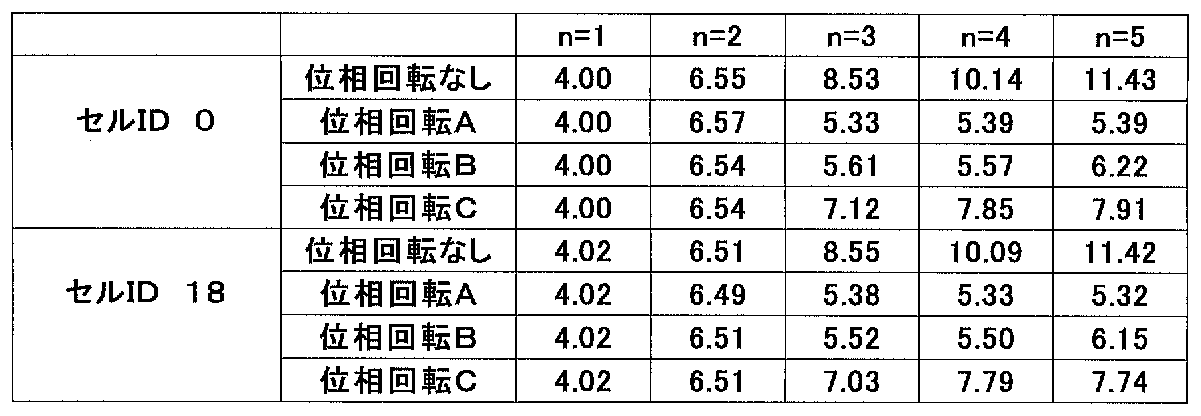
- physical cell IDs are 0 and 18, the number of transmission antennas is 1, and signal power other than the reference signal is 0.
- the phase rotation A in the table is when the phase rotation amount of each carrier component is (0 degrees, 180 degrees, 0 degrees, ⁇ 36 degrees, ⁇ 18 degrees), and the phase rotation B is (0 degrees, ⁇ 72 degrees). , ⁇ 108 degrees, 0 degrees, 180 degrees), and the phase rotation C is (0 degrees, ⁇ 36 degrees, ⁇ 72 degrees, ⁇ 108 degrees, ⁇ 144 degrees).
- CM can be reduced by applying phase rotation for each component carrier. Further, it can be seen from the comparison of the phase rotations A, B, and C that the CM value varies depending on the setting of the phase rotation amount. For this reason, the base station apparatus according to the present embodiment calculates in advance the optimum amount of phase rotation for each physical cell ID and refers to it as a table.
- the following table shows an example of a CM calculation result when a random QPSK signal is input as data other than the reference signal.
- the power of the reference signal is boosted by 3 dB from other signals.
- the CM value When data is inserted, the CM value is improved compared to the case of only the reference signal because the data is usually different for each carrier component. However, from the table, even when data is inserted, the CM is improved by phase rotation. It can be seen that the value is further improved. Furthermore, it can be seen from the two tables shown in the first embodiment that the phase rotation (C in this case) having poor characteristics with only the reference signal has poor characteristics even when data is included. Therefore, in this embodiment, the phase rotation amount set in advance in the physical cell ID / phase rotation amount correspondence table selects a combination that provides the best CM value when only the reference signal corresponding to the physical cell ID is arranged. It is also possible to calculate a CM value using another signal that is the same for each component carrier, such as a primary synchronization channel, a secondary synchronization channel, and a broadcast information channel, and create a table.
- An EUTRA mobile station apparatus can receive only one component carrier in an A-EUTRA frame.
- uniform phase rotation is applied to all subcarriers. Therefore, the mobile station apparatus that receives only the component carrier can compensate for the phase rotation applied in the base station apparatus when compensating for the propagation path without distinguishing from the phase rotation in the propagation path. This is the same for all other component carriers, and the mobile station device of EUTRA connected to the base station device in each component carrier can communicate without requiring additional processing according to the present invention. Is possible.
- the mobile station apparatus of A-EUTRA receives a plurality of component carrier signals simultaneously, if different phase rotations are applied to consecutive component carriers, propagation path compensation across the component carriers should be performed as it is. I can't.
- Examples of methods for solving the above problems include the following methods.
- Propagation path compensation across component carriers is not performed. That is, propagation path compensation is performed for each component carrier. Since it is assumed that a plurality of component carriers having different frequencies are allocated to the mobile station apparatus, it is possible to individually perform propagation path compensation for consecutive component carriers.
- the mobile station apparatus For a mobile station apparatus to which a plurality of component carriers are allocated, the mobile station apparatus includes a phase rotation amount for each component carrier in advance (for example, information broadcasted as system information (SIB)) in an upper control signal. Returns the phase rotation applied based on the information by reverse phase rotation and compensates the propagation path across the component carriers.
- SIB system information
- the mobile station apparatus also includes the same physical cell ID / phase rotation amount correspondence table as that of the base station apparatus, and the phase rotation amounts of all the component carriers based on the physical cell ID acquired by one component carrier. Get from.
- the phase rotation amount of each component carrier is limited to only two types of 0 degrees and 180 degrees, and as shown in FIG. 11, replicas of m reference signals from the end of each component carrier (unique to the physical cell ID) By using the reference signal generated by the mobile station apparatus corresponding to) and the actual received signal, and obtaining the phase rotation amount of the relevant location and comparing the difference in the phase rotation amount of the adjacent component carriers. It is estimated whether the difference in the amount of phase rotation is 0 degree or 180 degrees.
- the reference signal included in one OFDM symbol of the component carrier # 1 received by the mobile station apparatus in FIG. 11 is r1
- the reference signal of the component carrier # 2 is r2
- phase differences between m received reference signals and replicas from the end of the component carrier are obtained, and m average phase differences P are obtained.
- P1 in FIG. 11 uses conj () as a function for obtaining a complex conjugate.
- P2, P3, and P4 are obtained.
- phase difference between component carrier # 1 and component carrier # 2 and the phase difference between component carrier # 2 and component carrier # 3 can be obtained by comparing phase differences P1 and P2 and P3 and P4. For example, if the phase difference between P1 and P2 is between -90 degrees and 90 degrees, it can be determined that the phase difference is 0 degrees, and if it is less than -90 degrees or greater than 90 degrees, the phase difference is 180 degrees.
- the phase rotation amount is set to 0 degree and 180 degrees. However, if the phase difference is determined between ⁇ 45 degrees and 45 degrees as the phase rotation amount in units of 90 degrees, the phase difference is 0 degrees and 45 degrees. If the angle is between 135 degrees and 135 degrees, the phase difference is 90 degrees, if it is between 135 degrees and 225 degrees, the phase difference is 180 degrees, and if it is between 225 degrees and 315 degrees, the phase difference is 270 degrees (-90 degrees). It can also be judged.
- the phase difference is calculated by averaging (in the frequency direction) in units of one OFDM symbol, but a more accurate phase difference can be calculated by averaging in the time direction or both time and frequency directions. Is possible.
- FIG. 12 is a diagram showing a schematic configuration of a reception processing unit of the A-EUTRA mobile station apparatus that performs the above processing.
- the reception processing unit 1200 of the mobile station apparatus converts the received signal into a baseband signal at the receiving unit 1201.
- the synchronization processing unit 1202 detects a synchronization channel from the signal received by the reception unit 1201 and performs synchronization processing.
- the time / frequency conversion unit 1203 converts a time domain signal into a frequency domain signal at the timing synchronized by the synchronization processing unit 1202.
- the component carrier separation unit 1204 separates the frequency domain signal converted by the time / frequency conversion unit 1203 into the signal of each component carrier. Further, the reference signal obtained as a result of the separation is output to a phase difference calculation unit 1211 described later.
- phase rotation units 1205-1 to 1205-n give the phase rotation designated by the control unit described later to the signal of each component carrier separated by the component carrier separation unit 1204.
- Propagation path compensation units 1206-1 to 1206-n perform propagation path compensation based on the reference signals included in the signals whose phases are rotated by phase rotation units 1205-1 to 1205-n.
- Demodulating sections 1207-1 to 1207-n demodulate signals that have been subjected to propagation path compensation by propagation path compensation sections 1206-1 to 1206-n.
- Decoding sections 1208-1 to 1208-n decode the demodulated signals.
- the upper layer 1209 receives the decoded signal.
- Control unit 1210 controls each component.
- the physical cell ID and the position information within the frame of the reference signal are output to the phase difference calculation unit 1211.
- the phase difference calculation unit 1211 creates a reference signal replica based on the reference signal input from the component carrier separation unit 1204, the physical cell ID input from the control unit 1210, and the position information in the frame of the reference signal. .
- the phase difference between the replica and the reference signal is calculated and output to the phase difference determination unit 1212.
- the phase difference determination unit 1212 determines the phase rotation amount of each component carrier at the time of transmission from the phase difference between adjacent component carriers, and notifies the control unit 1210 of it.
- the received signal is converted into a baseband digital signal by the receiving unit 1201 and input to the synchronization processing unit 1202.
- the synchronization processing unit 1202 detects and synchronizes the frequency including the synchronization channel, and acquires physical cell ID information from the synchronization channel. Also, information necessary for communication such as antenna information and system frame number is acquired from the first broadcast channel. The acquired information is sent to the upper layer 1209. The upper layer 1209 notifies the control unit 1210 of information necessary for subsequent signal demodulation.
- the control unit 1210 controls each unit based on control information from the upper layer 1209.
- the output from receiving section 1201 is subjected to FFT conversion in units of one OFDM symbol based on timing information from control section 1210 in time / frequency conversion section 1203 and converted into a frequency domain signal.
- the converted frequency domain signal is input to component carrier separation section 1204.
- the component carrier separation unit 1204 separates the frequency domain signal into information for each component carrier, and outputs the information to the phase difference calculation unit 1211.
- the phase difference calculation unit 1211 calculates the phase difference between the reference signal replica and the reference signal of each component carrier input from the component carrier separation unit 1204 based on the physical cell ID notified from the control unit 1210.
- the calculated phase difference information of each component carrier is notified to the phase difference determination unit 1212.
- the phase difference determination unit 1212 determines the phase difference between adjacent component carriers from the phase difference information of each component carrier input from the phase difference calculation unit 1211 by the method described above, and notifies the control unit 1210 of the phase difference.
- the signal input to each of the phase rotation units 1205-1 to 1205-n is subjected to phase rotation opposite to the phase rotation applied by the base station apparatus.
- the phase-rotated signal is input to propagation path compensation units 1206-1 to 1206-n.
- Propagation path compensation units 1206-1 to 1206-n perform propagation path compensation based on the reference signal included in the received signal.
- the propagation path compensated signals are demodulated by demodulation sections 1207-1 to 1207-n, decoded by decoding sections 1208-1 to 1208-n, and notified to higher layer 1209.
- propagation path compensation is performed for each component carrier, but it is of course possible to perform propagation path compensation using reference signals of a plurality of component carriers.
- the base station apparatus 100 can improve the efficiency of power amplification in the transmission unit 108, and the mobile station apparatus can perform processing depending on the physical cell ID (for example, descrambling downlink signals, position / When performing code identification), it is possible to perform common processing for each component carrier, thereby simplifying the processing.
- the physical cell ID for example, descrambling downlink signals, position / When performing code identification
- the same physical cell ID can be given to downlink component carriers that share the uplink.
- applications other than propagation path compensation for example, channel When measuring quality, it can be used for signal processing when a plurality of base station devices and relay station devices called CoMP cooperate to transmit signals to one mobile station.
- FIG. 2A is a block diagram illustrating a schematic configuration of a base station apparatus according to the second embodiment.
- the base station apparatus 200 only adds the phase rotation units 105-1 to 105-n to the processing for each component carrier of the conventional base station apparatus. That is, base station apparatus 200 in the present embodiment encodes transmission data for each component carrier at encoding sections 101-1 to 101-n. Further, the signals encoded by the modulators 102-1 to 102-n are modulated.
- the SCH / RS generators 103-1 to 103-n generate a synchronization channel and a reference signal based on a physical cell ID (common to all component carriers) and generation timing notified from a control unit described later.
- Multiplexers 104-1 to 104-n receive the signals modulated by modulators 102-1 to 102-n and the synchronization channels and reference signals generated by SCH / RS generators 103-1 to 103-n. Multiplex in 1 OFDM symbol unit.
- FIG. 2B is a block diagram illustrating a schematic configuration of the phase rotation unit.
- the sign inversion unit 105a performs code inversion on the signals input from the multiplexing units 104-1 to 104-n.
- the replacement unit 105b replaces the real part and the imaginary part of the input signal.
- the component carrier multiplexing unit 106 maps the signal for one OFDM symbol phase-rotated by the phase rotation units 105-1 to 105-n for each component carrier in the frequency domain as shown in FIG.
- the frequency / time conversion unit 107 converts the frequency domain signal multiplexed by the component carrier multiplexing unit 106 into a time domain signal by IFFT calculation.
- the transmission unit 108 converts the digital signal converted into the time domain signal into an analog signal, performs power amplification on a carrier wave of a predetermined frequency, and transmits the analog signal. Note that the encoding unit 101-1 to the transmission unit 108 constitute a transmission processing unit.
- the base station apparatus 200 converts the signal received from the mobile station apparatus by the receiving unit 110 into a baseband digital signal. Further, the demodulation units 111-1 to 111-n demodulate the signals for each component carrier, and decode the signals demodulated by the decoding units 112-1 to 112-n.
- the reception unit 110 to decoding unit 112-n constitute a reception processing unit.
- the control unit 113 controls each component of the transmission processing unit and the reception processing unit. Upper layer 115 outputs a transmission signal to the transmission processing unit, receives the reception signal from the reception processing unit, and outputs control information to control unit 113.
- phase rotation units 105-1 to 105-n can be configured only by exchanging the real part and the imaginary part of the input signal expressed by complex numbers and reversing the sign. Specifically, when the phase rotation of 0 degree is performed, the input signal is output as it is, and when the phase rotation of 90 degrees is performed, the sign of the imaginary part of the input signal is inverted, and is replaced with the real part and output. When the phase rotation of 180 degrees is performed, the sign of the real part of the input signal is inverted and output. When the phase rotation of 270 degrees is performed, the sign of the real part of the input signal is inverted and replaced with the imaginary part. Output.
- the signal whose phase has been rotated by each component carrier is arranged on the subcarrier of the A-EUTRA frame by the component carrier multiplexing unit 106, and the frequency / time conversion unit 107 performs a time domain signal. And transmitted from the transmission unit 108.
- physical cell IDs are 0 and 18, the number of transmission antennas is 1, and signal power other than the reference signal is 0.
- the phase rotation D in the table is the case where the phase rotation amount of each carrier component is (0 degrees, 90 degrees, 90 degrees, 0 degrees, 180 degrees), and the phase rotation A is the same as in the first embodiment. .
- the base station apparatus can simplify the circuit configuration of the base station apparatus while maintaining the PAPR (CM) characteristics equivalent to those of the first embodiment.
- the advantage of this method is that, for example, for the purpose of eliminating a coverage hole (an area where radio waves do not reach such as a valley of a building) of a basic base station apparatus in a cell having four component carriers to be bundled, a simple base station apparatus as an extension Alternatively, even when a relay station device is installed in a cell and the same signal is transmitted as only a part of the component carriers of the basic base station device (for example, three component carriers), the simple base station device or relay station is used. It is possible to reduce the CM value of the signal transmitted from the apparatus.
- the optimum phase rotation amount is calculated for the number of component carriers to be bundled. May be.
- an A-EUTRA base station apparatus according to a third embodiment of the present invention will be described with reference to the drawings.
- EUTRA and A-EUTRA a mechanism called self-organized network (SON) that automatically optimizes the communication system has been proposed, and the physical cell ID is set / changed according to the situation of neighboring cells. It is considered to do.
- SON self-organized network
- the same physical cell ID may be obtained only between some component carriers. Therefore, in this embodiment, a base station apparatus when the physical cell ID of each component carrier is automatically determined will be described.
- FIG. 3 is a block diagram showing a schematic configuration of a base station apparatus according to the third embodiment.
- This base station apparatus 300 employs a configuration in which a CM calculation unit 116 is added to the configuration of the conventional base station apparatus.
- Encoding units 101-1 to 101-n code transmission data for each component carrier. Further, the signals encoded by the modulators 102-1 to 102-n are modulated. Further, the SCH / RS generators 103-1 to 103-n generate a synchronization channel and a reference signal based on a physical cell ID (common to all component carriers) and generation timing notified from a control unit described later.
- Multiplexers 104-1 to 104-n receive the signals modulated by modulators 102-1 to 102-n and the synchronization channels and reference signals generated by SCH / RS generators 103-1 to 103-n. Multiplex in 1 OFDM symbol unit.
- the phase rotation units 105-1 to 105-n uniformly rotate the signals multiplexed by the multiplexing units 104-1 to 104-n by a phase designated by the control unit described later.
- the component carrier multiplexing unit 106 maps the signal for one OFDM symbol whose phase is rotated by the phase rotation units 105-1 to 105-n for each component carrier in the frequency domain as shown in FIG.
- the frequency / time conversion unit 107 converts the frequency domain signal multiplexed by the component carrier multiplexing unit 106 into a time domain signal by IFFT calculation.
- the CM calculation unit 116 calculates the CM of the signal converted by the frequency / time conversion unit 107.
- the transmission unit 108 converts the digital signal converted into the time domain signal into an analog signal, performs power amplification on a carrier wave of a predetermined frequency, and transmits the analog signal. Note that the encoding unit 101-1 to the transmission unit 108 constitute a transmission processing unit.
- the base station apparatus 300 converts a signal received from the mobile station apparatus by the receiving unit 110 into a baseband digital signal as a reception processing unit. Further, the demodulation units 111-1 to 111-n demodulate the signals for each component carrier, and decode the signals demodulated by the decoding units 112-1 to 112-n.
- the reception unit 110 to decoding unit 112-n constitute a reception processing unit.
- the control unit 113 controls each component of the transmission processing unit and the reception processing unit.
- Upper layer 115 outputs a transmission signal to the transmission processing unit, receives the reception signal from the reception processing unit, and outputs control information to control unit 113.
- the base station apparatus 300 performs the following operation when the physical cell ID is determined or changed.
- the control unit 113 notifies the SCH / RS generation units 103-1 to 103-n of the physical cell ID for each component carrier.
- SCH / RS generating sections 103-1 to 103-n generate reference signals and output them to multiplexing sections 104-1 to 104-n.
- Multiplexing sections 104-1 to 104-n output the signals other than the reference signal as null signals to phase rotation sections 105-1 to 105-n.
- the control unit 113 notifies the phase rotation units 105-1 to 105-n of the component carriers having the same physical cell ID of different phase rotation amounts, and the phase rotation units 105-1 to 105 of the other component carriers. Specify 0 degree of phase rotation for -n.
- the phase rotation units 105-1 to 105-n add the phase rotation amount designated by the control unit 113 to the input signals from the multiplexing units 104-1 to 104-n.
- the signal of each component carrier whose phase has been rotated is multiplexed by the component carrier multiplexing unit 106 and converted into a time domain signal by the frequency / time conversion unit 107.
- the output signal of the frequency / time conversion unit 107 is input to the CM calculation unit 116, and the CM value is calculated.
- the calculated CM value is input to the control unit 113, and the process is repeated by changing the phase rotation amount of the component carrier having the same physical cell ID until the CM value satisfies the condition. Examples of conditions that the CM value satisfies include the following. (1) The CM value is below a predetermined threshold. (2) The CM value is the lowest among a limited number of combinations of phase rotation amounts.
- the transmission unit 108 After the phase rotation amount is set by the above processing, the transmission unit 108 performs transmission using the set phase rotation amount, as in the processing of the base station apparatus of the first embodiment.
- the efficiency of power amplification in the transmission unit 108 can be improved.
- FIG. 4 is a block diagram illustrating a schematic configuration of the base station apparatus according to the present embodiment.
- This base station apparatus 400 employs a configuration in which a physical cell ID / phase rotation offset amount correspondence table 401, a physical cell ID / phase rotation amount correspondence table 402, and a counter 403 are added to the configuration of the conventional base station device.
- Encoding units 101-1 to 101-n code transmission data for each component carrier. Further, the signals encoded by the modulators 102-1 to 102-n are modulated. Further, the SCH / RS generators 103-1 to 103-n generate a synchronization channel and a reference signal based on a physical cell ID (common to all component carriers) and generation timing notified from a control unit described later.
- Multiplexers 104-1 to 104-n receive the signals modulated by modulators 102-1 to 102-n and the synchronization channels and reference signals generated by SCH / RS generators 103-1 to 103-n. Multiplex in 1 OFDM symbol unit.
- the phase rotation units 105-1 to 105-n uniformly rotate the signals multiplexed by the multiplexing units 104-1 to 104-n by a phase designated by the control unit described later.
- the component carrier multiplexing unit 106 maps the signal for one OFDM symbol whose phase is rotated by the phase rotation units 105-1 to 105-n for each component carrier in the frequency domain as shown in FIG.
- the frequency / time conversion unit 107 converts the frequency domain signal multiplexed by the component carrier multiplexing unit 106 into a time domain signal by IFFT calculation.
- the transmission unit 108 converts the digital signal converted into the time domain signal into an analog signal, performs power amplification on a carrier wave of a predetermined frequency, and transmits the analog signal. Note that the encoding unit 101-1 to the transmission unit 108 constitute a transmission processing unit.
- the base station apparatus 400 converts the signal received from the mobile station apparatus by the receiving unit 110 into a baseband digital signal. Further, the demodulation units 111-1 to 111-n demodulate the signals for each component carrier, and decode the signals demodulated by the decoding units 112-1 to 112-n.
- the reception unit 110 to decoding unit 112-n constitute a reception processing unit.
- the control unit 113 controls each component of the transmission processing unit and the reception processing unit.
- Upper layer 115 outputs a transmission signal to the transmission processing unit, receives the reception signal from the reception processing unit, and outputs control information to control unit 113.
- the physical cell ID / phase rotation offset amount correspondence table 401 stores the physical cell ID and the phase rotation offset amount in the time direction in association with each other.
- the physical cell ID / phase rotation amount correspondence table 402 stores the physical cell ID and each phase rotation amount of the component carrier in association with each other.
- the counter 403 performs counting under the control of the control unit 113.
- the component carrier transmission signals generated by the multiplexing units 104-1 to 104-n are transmitted to the component carriers designated by the control unit 113 in the phase rotation units 105-1 to 105-n.
- a separate phase rotation is added.
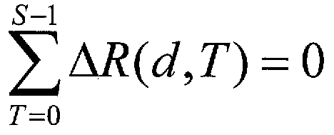
- Each phase rotation amount is specified by the control unit 113 based on the values of the physical cell ID / phase rotation amount correspondence table 402, the physical cell ID / phase rotation offset amount correspondence table 401, and the counter 403.
- the physical cell ID is d
- the phase rotation amount of the component carrier f stored in the physical cell ID / phase rotation amount correspondence table is Rc (d, f)
- the physical cell ID / phase rotation offset amount is Is given by a mathematical formula.
- phase rotation amount R is added with a different offset amount for each physical cell ID every time it is counted up, and returns to the phase rotation amount before the offset is added again after the period S.
- the amount of phase rotation per subframe changes in a period of one frame (10 subframes).
- the phase rotation amount can be changed in one subframe period.
- the phase rotation amount for each frame changes with a period of a plurality of frames.
- a frame serving as a reference for starting counting can be determined based on system frame information (SFN) included in the first broadcast channel (P-BCH).
- the signal whose phase is rotated by each component carrier is arranged on the subcarrier of the A-EUTRA frame by the component carrier multiplexing unit, and is converted into a time domain signal by the frequency / time conversion unit and transmitted from the transmission unit, as in the conventional case. Sent.
- An EUTRA mobile station apparatus can receive only one component carrier in an A-EUTRA frame.
- uniform phase rotation is applied to all subcarriers within the count-up period of the counter.
- a mobile station apparatus that receives only the component carrier can compensate for the phase rotation added in the base station apparatus when the mobile station apparatus that performs propagation path compensation for each count-up period compensates the propagation path.
- the EUTRA mobile station apparatus connected to the base station apparatus with each component carrier can perform communication without requiring additional processing according to the present invention. Further, even when propagation path compensation is performed beyond the count-up cycle, the error of propagation path compensation can be reduced by suppressing the value of ⁇ R within the assumption of time variation of the propagation path.
- FIG. 5 is a diagram illustrating a schematic configuration of a reception processing unit of the A-EUTRA mobile station apparatus according to the present embodiment.
- the reception unit 501 converts the reception signal into a baseband signal.
- the synchronization processing unit 502 detects a synchronization channel from the signal received by the reception unit 501 and performs synchronization processing.
- the time / frequency conversion unit 503 converts a time domain signal into a frequency domain signal at the timing synchronized by the synchronization processing unit 502.
- the component carrier separation unit 504 separates the frequency domain signal converted by the time / frequency conversion unit 503 into the signal of each component carrier.
- phase rotation units 505-1 to 505-n give the phase rotation specified by the control unit described later to the signal of each component carrier separated by the component carrier separation unit 504.
- Propagation path compensation units 506-1 to 506-n perform propagation path compensation based on the reference signal included in the signals whose phases have been rotated by phase rotation units 505-1 to 505-n.
- Demodulating sections 507-1 to 507-n demodulate the signals that have been subjected to propagation path compensation by propagation path compensation sections 506-1 to 506-n.
- Decoding sections 508-1 to 508-n decode the demodulated signals.
- the upper layer 509 receives the decoded signal.
- Control unit 510 controls each component.
- the physical cell ID / phase rotation amount correspondence table 511 stores the physical cell ID and each phase rotation amount of the component carrier in association with each other.
- the physical cell ID / phase rotation offset amount correspondence table 512 stores the physical cell ID and the phase rotation offset amount in the time direction in association with each other.
- the counter 513 performs counting under the control of the control unit 510.
- the received signal is converted into a baseband digital signal by the receiving unit 501 and input to the synchronization processing unit 502.
- the synchronization processing unit 502 detects and synchronizes the frequency including the synchronization channel, and acquires physical cell ID information from the synchronization channel. Also, information necessary for communication such as antenna information and system frame number is acquired from the first broadcast channel. The acquired information is sent to the upper layer 509, and the upper layer 509 notifies the control unit 510 of information necessary for subsequent signal demodulation.
- the control unit 510 controls each unit based on the control information from the upper layer 509.
- An output from the receiving unit 501 is a time / frequency converting unit 503, which performs FFT conversion in units of one OFDM symbol based on timing information from the control unit 510 and converts the signal into a frequency domain signal.
- the converted frequency domain signal is separated into information for each component carrier by the component carrier separation unit 504, and is output to each of the phase rotation units 505-1 to 505-n.
- the control unit 510 counts up the counter 513 based on the synchronization timing and system frame information notified from the upper layer 509, and the physical cell ID / phase rotation amount correspondence table 511, physical cell ID / phase rotation offset amount correspondence table. Based on the values of 512 and the counter 513, the phase rotation opposite to the phase rotation added by the base station apparatus is added to each component carrier.
- the phase rotated signal is input to the propagation path compensation units 506-1 to 506-n, and propagation path compensation is performed based on the reference signal included in the received signal.
- the signals subjected to propagation path compensation are demodulated by the demodulation units 507-1 to 507-n, decoded by the decoding units 508-1 to 508-n, and notified to the upper layer 509.
- the A-EUTRA mobile station apparatus also removes the phase rotation offset added by the base station apparatus in front of the propagation path compensation unit when performing propagation path compensation exceeding the count-up period. Therefore, propagation path compensation can be performed with high accuracy.
- the base station apparatus of this embodiment when the same physical cell ID is used in the component carrier, by using the base station apparatus of this embodiment, compatibility with EUTRA is suppressed while suppressing an increase in PAPR (CM). And propagation path compensation in the EUTRA mobile station apparatus and the A-EUTRA mobile station apparatus becomes possible. Also, by specifying a different phase rotation offset amount for each physical cell ID, the phase of the transmission signal between the base stations changes independently at the count-up cycle, and the mobile station apparatus that receives the signal at the cell boundary Interference can be randomized.
- CM PAPR
- the table is provided to generate the phase rotation amount.
- the offset amount may be set using a sequence that is uniquely calculated from the physical cell ID.
- the cycle S is an even number, and a code string composed of S / 2 “1” s and S / 2 “0s” is generated by the number of physical cell IDs, and “0” is sequentially generated from the top of the code string. If it is, the offset is x degrees, and if it is “1”, the offset is ⁇ x degrees.
- each component carrier The phase rotation amount corresponding to the component carrier number in the physical cell ID is applied.
- the phase rotation amount of each component carrier is (Ro1, Ro2, Ro3, Ro4, However, if the physical cell ID of each component carrier is (0, 1, 2, 0, 0), the phase rotation amount is (Ro1, Ro7, Ro13, Ro4, Ro5).
- phase rotation amount of all component carriers is set to 0.
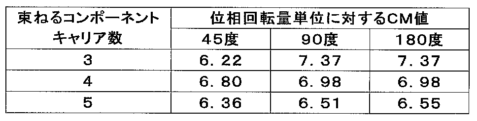
- the following table shows the phase rotation when the number of component carriers to be bundled is 3, 4, 5 and the physical cell ID is 31, and the unit of phase rotation amount of each component carrier is 45 degrees, 90 degrees, and 180 degrees.
- the best CM value is derived from all combinations of phase rotations in units.
- the mobile station apparatus that receives the signal transmitted from the base station apparatus is connected to the rotation amount unit of the phase difference determination unit of the mobile station apparatus of FIG. 12 described in the first embodiment. By changing according to the number of component carriers, determination errors can be reduced.
- the base station apparatus that bundles and transmits the component carriers has been described.
- the present invention is not limited to this, and the above-described phase rotation unit is also used in the uplink of the mobile station apparatus. Can be applied to the transmission processing of the mobile station apparatus.
- the phase rotation amount is calculated and determined based on the physical cell ID.
- This is a reference signal or primary synchronization channel determined based on the physical cell ID. This is equivalent to determining the amount of phase rotation based on the signal waveform when transmitting the secondary synchronization channel or broadcast information channel.
- Base station apparatus 101-1 to 101-n Encoding unit 102-1 to 102-n Modulating unit 103-1 to 103-n SCH / RS generating unit 104-1 to 104-n Multiplexing unit 105 -1 to 105-n Phase rotation unit 106 Component carrier multiplexing unit 107 Frequency / time conversion unit 108 Transmission unit 110 Reception unit 111-1 to 111-n Demodulation unit 112-1 to 112-n Decoding unit 113 Control unit 114 Physical cell ID / phase rotation amount correspondence table 115 Upper layer 116 CM calculation unit 401 Physical cell ID / phase rotation offset amount correspondence table 402 Physical cell ID / phase rotation amount correspondence table 403 Counter 500 Reception processing unit 501 Reception unit 502 Synchronization processing unit 503 Time / Frequency conversion unit 504 Component carrier separation units 505-1 to 505- Phase rotation units 506-1 to 506-n Propagation path compensation units 507-1 to 507-n Demodulation units 508-1 to 508-n Decoding unit
Landscapes
- Engineering & Computer Science (AREA)
- Signal Processing (AREA)
- Computer Networks & Wireless Communication (AREA)
- Mobile Radio Communication Systems (AREA)
Abstract
Description

以下、本発明の第1の実施形態に係るA-EUTRAの基地局装置について、図面を参照しながら説明する。図1は、本実施形態に係る基地局装置の概略構成を示すブロック図である。本実施形態における基地局装置100は、符号部101-1~101-nでコンポーネントキャリアごとに送信データの符号を行なう。また、変調部102-1~102-nで符号化した信号の変調を行なう。また、SCH/RS生成部103-1~103-nで後述する制御部から通知される(コンポーネントキャリアすべてで共通の)物理セルIDと生成タイミングに基づいて同期チャネルと参照信号を生成する。

(1)コンポーネントキャリアを跨ぐ伝播路補償を行なわない。すなわち、コンポーネントキャリア毎に伝播路補償を行なう。移動局装置は離れた周波数のコンポーネントキャリアを複数割り当てられることも想定されるため、連続するコンポーネントキャリアを個別に伝播路補償を行なうことは可能である。
(2)複数のコンポーネントキャリアを割り当てられる移動局装置に対しては上位の制御信号において事前に(例えばシステム情報(SIB)として報知する情報に)コンポーネントキャリアごとの位相回転量を含め、移動局装置はその情報をもとに加えられた位相回転を逆位相回転により戻し、コンポーネントキャリアを跨ぐ伝播路補償を行なう。
(3)移動局装置においても基地局装置と同じ物理セルID/位相回転量対応テーブルを具備し、ひとつのコンポーネントキャリアで取得した物理セルIDをもとにすべてのコンポーネントキャリアの位相回転量をテーブルから取得する。
(4)各コンポーネントキャリアの位相回転量を0度、180度の2種類のみに限定し、図11に示すように、各コンポーネントキャリアの端からm個の参照信号のレプリカ(物理セルIDに一意に対応する移動局装置で生成した参照信号)と実際の受信信号を用いて、当該箇所の位相回転量を求め、隣接するコンポーネントキャリアの位相回転量の差を比較することにより、隣接するコンポーネントキャリアの位相回転量の差が0度か180度かを推定する。

次に、本発明の第2の実施形態に係るA-EUTRAの基地局装置について、図面を参照しながら説明する。図2Aは、第2の実施形態に係る基地局装置の概略構成を示すブロック図である。この基地局装置200は、第1の実施形態とは異なり、従来の基地局装置のコンポーネントキャリアごとの処理に位相回転部105-1~105-nを追加するのみとする。すなわち、本実施形態における基地局装置200は、符号部101-1~101-nでコンポーネントキャリアごとに送信データの符号を行なう。また、変調部102-1~102-nで符号化した信号の変調を行なう。また、SCH/RS生成部103-1~103-nで後述する制御部から通知される(コンポーネントキャリアすべてで共通の)物理セルIDと生成タイミングに基づいて同期チャネルと参照信号を生成する。多重部104-1~104-nは、変調部102-1~102-nで変調された信号と、SCH/RS生成部103-1~103-nで生成された同期チャネルや参照信号とを1OFDMシンボル単位で多重する。

次に、本発明の第3の実施形態に係るA-EUTRAの基地局装置について、図面を参照しながら説明する。EUTRAやA-EUTRAでは、通信システムの最適化を自動で行なう自己組織型ネットワーク(SON:Self Organized Network)と呼ばれる仕組みが提案されており、隣接セルの状況に応じて物理セルIDを設定・変更することなどが考えられている。コンポーネントキャリアごとにSONにより最適化を行なう際には、一部のコンポーネントキャリア間でのみ同一物理セルIDとなる場合などがある。そのため、本実施形態では、各コンポーネントキャリアの物理セルIDが自動的に決定される場合の基地局装置について説明する。
(1)CM値が既定の閾値を下回る。
(2)有限個の位相回転量の組み合わせのうち、もっともCM値が低くなる。
次に、本発明の第4の実施形態に係るA-EUTRAの基地局装置について、図面を参照しながら説明する。本実施形態では、物理セルIDに応じて、時間方向の位相回転量を制御する。物理セルIDに応じて時間方向の位相回転量を制御することにより、隣接する(異なる物理セルIDをもつ)セル間の信号が、時間により独立して位相回転し、干渉のランダマイズ化を図ることができる。図4は、本実施形態に係る基地局装置の概略構成を示すブロック図である。この基地局装置400は、従来の基地局装置の構成に、物理セルID/位相回転オフセット量対応テーブル401、物理セルID/位相回転量対応テーブル402、およびカウンタ403を追加した構成を採る。

次に、本発明の第5の実施形態に係るA-EUTRAの基地局装置について、説明する。第3の実施形態では、一部のコンポーネントキャリアの物理セルIDが異なる場合において、CMを再度計算して、位相回転量を求めた。本実施形態では、CMを計算することなく、以下の何れかの処理とすることを予め規定する。

次に、本発明の第6の実施形態に係るA-EUTRAの基地局装置について説明する。前記第2の実施形態では、位相回転量を90度単位とすることでPAPR(CM)特性を維持しつつ回路規模の簡略化を図った。本実施形態では、束ねるコンポーネントキャリア数に応じて位相回転量の単位を変更することで回路規模の増大を抑えつつ効果的にPAPR(CM)特性を得る手法を説明する。
101-1~101-n 符号部
102-1~102-n 変調部
103-1~103-n SCH/RS生成部
104-1~104-n 多重部
105-1~105-n 位相回転部
106 コンポーネントキャリア多重部
107 周波数/時間変換部
108 送信部
110 受信部
111-1~111-n 復調部
112-1~112-n 復号部
113 制御部
114 物理セルID/位相回転量対応テーブル
115 上位レイヤ
116 CM算出部
401 物理セルID/位相回転オフセット量対応テーブル
402 物理セルID/位相回転量対応テーブル
403 カウンタ
500 受信処理部
501 受信部
502 同期処理部
503 時間/周波数変換部
504 コンポーネントキャリア分離部
505-1~505-n 位相回転部
506-1~506-n 伝播路補償部
507-1~507-n 復調部
508-1~508-n 復号部
509 上位レイヤ
510 制御部
511 物理セルID/位相回転量対応テーブル
512 物理セルID/位相回転オフセット量対応テーブル
513 カウンタ
1200 受信処理部
1201 受信部
1202 同期処理部
1203 時間/周波数変換部
1204 コンポーネントキャリア分離部
1205-1~1205-n 位相回転部
1206-1~1206-n 伝播路補償部
1207-1~1207-n 復調部
1208-1~1208-n 復号部
1209 上位レイヤ
1210 制御部
1211 位相差算出部
1212 位相差判定部
Claims (14)
- 複数のコンポーネントキャリアを束ねて送信する基地局装置であって、
コンポーネントキャリアごとに位相回転を施す位相回転部と、
前記位相回転が施されたコンポーネントキャリアを移動局装置に対して送信する送信部と、を備え、
前記位相回転量は、コンポーネントキャリアで共通な物理セルIDに基づいて決定されることを特徴とする基地局装置。 - CM(Cubic Metric)値に基づいて予め設定された位相回転量と、物理セルIDと対応付けた物理セルID/位相回転量対応テーブルをさらに備え、
前記位相回転部は、前記物理セルID/位相回転量対応テーブルに基づいてコンポーネントキャリアごとに位相回転を施すことを特徴とする請求項1記載の基地局装置。 - 前記位相回転部は、
符号反転を行なう符号反転部と、
入力信号の実数部と虚数部とを入れ替える入れ替え部と、を備えることを特徴とする請求項1記載の基地局装置。 - 複数のコンポーネントキャリアを束ねて送信する基地局装置であって、
コンポーネントキャリアごとに位相回転を施す位相回転部と、
コンポーネントキャリアのいずれかの物理セルIDが変更された場合に、CM値を算出するCM算出部と、
前記CM値に基づいた位相回転量を前記位相回転部に設定する制御部と、
前記位相回転が施されたコンポーネントキャリアを移動局装置に対して送信する送信部と、を備えることを特徴とする基地局装置。 - 前記CM値は、各コンポーネントキャリアの参照信号、プライマリ同期チャネル、セカンダリ同期チャネル若しくは報知情報チャネルまたはこれらの組み合わせを送信信号とした際の値であることを特徴とする請求項2または請求項4記載の基地局装置。
- 複数のコンポーネントキャリアを束ねて送信する基地局装置であって、
コンポーネントキャリアごとに位相回転を施す位相回転部と、
前記位相回転が施されたコンポーネントキャリアを移動局装置に対して送信する送信部と、を備え、
前記位相回転量は、物理セルIDに基づいて決定されると共に、一定の時間間隔で物理セルIDに基づいて変更されることを特徴とする基地局装置。 - 前記物理セルIDおよびコンポーネントキャリアの各位相回転量を対応付けた物理セルID/位相回転量対応テーブルと、
前記物理セルIDおよび時間方向の位相回転オフセット量を対応付けて格納する物理セルID/位相回転オフセット量対応テーブルと、をさらに備え、
前記位相回転部は、前記物理セルID/位相回転量対応テーブルおよび物理セルID/位相回転オフセット量対応テーブルに基づいてコンポーネントキャリアごとに位相回転を施すことを特徴とする請求項6記載の基地局装置。 - 束ねるコンポーネントキャリア数に応じて位相回転量の単位を変更することを特徴とする請求項1記載の基地局装置。
- 請求項1記載の基地局装置と無線通信を行なう移動局装置であって、
前記基地局装置から受信した信号に対して、前記基地局装置により施された位相回転と逆の位相回転を施すことを特徴とする移動局装置。 - 前記基地局装置から、上位の制御信号によって予め通知された位相回転の量に基づいて、前記逆の位相回転を施すことを特徴とする請求項9記載の移動局装置。
- 隣接するコンポーネントキャリア間の位相差から各コンポーネントキャリアの位相回転量を判定する位相差判定部を備え、
前記位相差判定部で判定された位相回転量に基づいて、前記逆の位相回転を施すことを特徴とする請求項9記載の移動局装置。 - 請求項2記載の基地局装置と無線通信を行なう移動局装置であって、
CM値に基づいて予め設定された位相回転量と、物理セルIDと対応付けた物理セルID/位相回転量対応テーブルを備え、
前記物理セルID/位相回転量対応テーブルと、接続対象の基地局装置の物理セルIDとから位相回転の量を取得し、前記基地局装置から受信した信号に対して、前記基地局装置により施された位相回転と逆の位相回転を施すことを特徴とする移動局装置。 - 請求項8記載の基地局装置と無線通信を行なう移動局装置であって、
前記基地局装置から受信した信号に対して、束ねられたコンポーネントキャリア数に対応する位相回転量の単位で、前記基地局装置により施された位相回転と逆の位相回転を施すことを特徴とする移動局装置。 - 請求項1、請求項4または請求項6のいずれかに記載の基地局装置と、
EUTRA(Evolved Universal Terrestrial Radio Access)に対応する移動局装置と、
A-EUTRA(Advanced EUTRA)に対応する移動局装置と、により構成されることを特徴とする移動通信システム。
Priority Applications (2)
| Application Number | Priority Date | Filing Date | Title |
|---|---|---|---|
| JP2010548450A JPWO2010087214A1 (ja) | 2009-01-27 | 2010-01-06 | 基地局装置、移動局装置および移動通信システム |
| US13/146,264 US20110280189A1 (en) | 2009-01-27 | 2010-01-06 | Base station apparatus, mobile station apparatus, and mobile communication system |
Applications Claiming Priority (2)
| Application Number | Priority Date | Filing Date | Title |
|---|---|---|---|
| JP2009015912 | 2009-01-27 | ||
| JP2009-015912 | 2009-01-27 |
Publications (1)
| Publication Number | Publication Date |
|---|---|
| WO2010087214A1 true WO2010087214A1 (ja) | 2010-08-05 |
Family
ID=42395476
Family Applications (1)
| Application Number | Title | Priority Date | Filing Date |
|---|---|---|---|
| PCT/JP2010/050070 Ceased WO2010087214A1 (ja) | 2009-01-27 | 2010-01-06 | 基地局装置、移動局装置および移動通信システム |
Country Status (3)
| Country | Link |
|---|---|
| US (1) | US20110280189A1 (ja) |
| JP (1) | JPWO2010087214A1 (ja) |
| WO (1) | WO2010087214A1 (ja) |
Cited By (7)
| Publication number | Priority date | Publication date | Assignee | Title |
|---|---|---|---|---|
| CN102438247A (zh) * | 2011-11-03 | 2012-05-02 | 中兴通讯股份有限公司 | 物理小区标识分配、获取方法,基站及用户设备 |
| WO2013094106A1 (ja) * | 2011-12-19 | 2013-06-27 | 日本電気株式会社 | 送信装置および無線信号送信方法 |
| JPWO2011145151A1 (ja) * | 2010-05-21 | 2013-07-22 | 富士通株式会社 | 送信機、受信機、通信システム、通信方法 |
| JP2016506216A (ja) * | 2013-01-25 | 2016-02-25 | クゥアルコム・インコーポレイテッドQualcomm Incorporated | 共通基準信号の位相不連続性 |
| JP2017527215A (ja) * | 2014-09-02 | 2017-09-14 | クゥアルコム・インコーポレイテッドQualcomm Incorporated | Eotdoaのためのlteにおけるprs周波数オフセットおよびミュートパターンのランダム化 |
| JP2019525532A (ja) * | 2016-06-24 | 2019-09-05 | テレフオンアクチーボラゲット エルエム エリクソン(パブル) | マッシブmimoのための送信器アーキテクチャ |
| JP2020507269A (ja) * | 2017-01-27 | 2020-03-05 | クアルコム,インコーポレイテッド | チャネル干渉低減のための技法および装置 |
Families Citing this family (7)
| Publication number | Priority date | Publication date | Assignee | Title |
|---|---|---|---|---|
| KR20130142932A (ko) * | 2012-06-19 | 2013-12-30 | 한국전자통신연구원 | 무선랜 시스템의 오에프디엠 전송 방법 및 장치 |
| US9438457B2 (en) * | 2013-03-25 | 2016-09-06 | Maxlinear, Inc. | Peak to average power ratio suppression |
| CN104581922B (zh) * | 2013-10-23 | 2019-06-18 | 中兴通讯股份有限公司 | 一种lte系统中主同步信号在时域实现的方法和装置 |
| US10693696B2 (en) * | 2016-11-22 | 2020-06-23 | Samsung Electronics Co., Ltd. | Apparatus and method for transmitting and receiving signals in wireless communication system |
| WO2020250398A1 (ja) * | 2019-06-13 | 2020-12-17 | 株式会社Nttドコモ | 通信装置 |
| US11368236B2 (en) * | 2019-09-06 | 2022-06-21 | Cisco Technology, Inc. | Detection and decoding of wireless synchronization signals |
| US20230412440A1 (en) * | 2020-12-18 | 2023-12-21 | Telefonaktiebolaget Lm Ericsson (Publ) | Transmitting synchronisation signals on multiple carriers |
Family Cites Families (3)
| Publication number | Priority date | Publication date | Assignee | Title |
|---|---|---|---|---|
| CN101616438A (zh) * | 2008-06-24 | 2009-12-30 | 华为技术有限公司 | 多载波系统信号发射、接收方法及装置 |
| CN104579617B (zh) * | 2008-10-22 | 2019-06-28 | 夏普株式会社 | 移动台设备及其执行的方法、基站设备及其执行的方法 |
| KR101603651B1 (ko) * | 2008-10-30 | 2016-03-15 | 엘지전자 주식회사 | 단일 주파수 대역만을 사용하는 제1 사용자 기기와 복수의 주파수 대역을 사용하는 제2 사용자 기기를 지원하는 무선 통신 시스템에 있어서, 사용자 기기와 기지국 간의 무선 통신 방법 |
-
2010
- 2010-01-06 US US13/146,264 patent/US20110280189A1/en not_active Abandoned
- 2010-01-06 WO PCT/JP2010/050070 patent/WO2010087214A1/ja not_active Ceased
- 2010-01-06 JP JP2010548450A patent/JPWO2010087214A1/ja active Pending
Non-Patent Citations (3)
| Title |
|---|
| LG ELECTRONICS: "Issues on the CM increase due to the repeated DL RS", 3GPP TSG RAN WG1 #55BIS R1- 090209, 12 January 2009 (2009-01-12) * |
| SAMSUNG: "DL RS for carrier aggregation with reduced PAPR", 3GPP TSG RAN WG1 #55BIS R1-090096, 12 January 2009 (2009-01-12) * |
| TEXAS INSTRUMENTS: "Extending PUCCH Formats 1/1a/ 1b and 2/2a/2b for the Case of Multiple Components Carriers", 3GPP TSG RAN WG1 #55 RL- 084450, 10 November 2008 (2008-11-10) * |
Cited By (14)
| Publication number | Priority date | Publication date | Assignee | Title |
|---|---|---|---|---|
| JPWO2011145151A1 (ja) * | 2010-05-21 | 2013-07-22 | 富士通株式会社 | 送信機、受信機、通信システム、通信方法 |
| US8982822B2 (en) | 2010-05-21 | 2015-03-17 | Fujitsu Limited | Transmitter, receiver, communication system, and communication method |
| CN102438247B (zh) * | 2011-11-03 | 2018-02-13 | 中兴通讯股份有限公司 | 物理小区标识分配及获取方法、基站及用户设备 |
| WO2013063896A1 (zh) * | 2011-11-03 | 2013-05-10 | 中兴通讯股份有限公司 | 物理小区标识分配、获取方法,基站及用户设备 |
| CN102438247A (zh) * | 2011-11-03 | 2012-05-02 | 中兴通讯股份有限公司 | 物理小区标识分配、获取方法,基站及用户设备 |
| WO2013094106A1 (ja) * | 2011-12-19 | 2013-06-27 | 日本電気株式会社 | 送信装置および無線信号送信方法 |
| JPWO2013094106A1 (ja) * | 2011-12-19 | 2015-04-27 | 日本電気株式会社 | 送信装置および無線信号送信方法 |
| US9287906B2 (en) | 2011-12-19 | 2016-03-15 | Nec Corporation | Transmission apparatus and wireless signal transmission method |
| JP2016506216A (ja) * | 2013-01-25 | 2016-02-25 | クゥアルコム・インコーポレイテッドQualcomm Incorporated | 共通基準信号の位相不連続性 |
| US9825745B2 (en) | 2013-01-25 | 2017-11-21 | Qualcomm Incorporated | Common reference signal phase discontinuity and sequence initialization |
| JP2017527215A (ja) * | 2014-09-02 | 2017-09-14 | クゥアルコム・インコーポレイテッドQualcomm Incorporated | Eotdoaのためのlteにおけるprs周波数オフセットおよびミュートパターンのランダム化 |
| US10439775B2 (en) | 2014-09-02 | 2019-10-08 | Qualcomm Incorporated | Randomization of PRS frequency offsets and muting patterns in LTE for EOTDOA |
| JP2019525532A (ja) * | 2016-06-24 | 2019-09-05 | テレフオンアクチーボラゲット エルエム エリクソン(パブル) | マッシブmimoのための送信器アーキテクチャ |
| JP2020507269A (ja) * | 2017-01-27 | 2020-03-05 | クアルコム,インコーポレイテッド | チャネル干渉低減のための技法および装置 |
Also Published As
| Publication number | Publication date |
|---|---|
| JPWO2010087214A1 (ja) | 2012-08-02 |
| US20110280189A1 (en) | 2011-11-17 |
Similar Documents
| Publication | Publication Date | Title |
|---|---|---|
| US12004107B2 (en) | Time and frequency synchronization | |
| WO2010087214A1 (ja) | 基地局装置、移動局装置および移動通信システム | |
| KR102542055B1 (ko) | 무선 시스템에서의 동기 신호 블록 인덱스 및 타이밍 지시를 위한 방법 및 장치 | |
| US10708028B2 (en) | Method and apparatus for reference signals in wireless system | |
| US10362610B2 (en) | Method and apparatus for mapping initial access signals in wireless systems | |
| KR101928879B1 (ko) | 참조 신호를 전송하는 방법 및 장치 | |
| CN109314624B (zh) | 无线通信系统中发送和接收相位噪声补偿参考信号的方法及其装置 | |
| US9344245B2 (en) | Apparatus and method for allocating channel state information-reference signal in wireless communication system | |
| KR101701899B1 (ko) | 무선시스템에서 하향링크 통신을 위한 8개 송신안테나 기준신호 설계 | |
| US9503238B2 (en) | Control channel transmission method and apparatus for transmitting dedicated reference signal in wireless communication system | |
| EP2811797B1 (en) | Base station device, mobile terminal device, and communication method | |
| US9167598B2 (en) | Base station apparatus, mobile station apparatus, radio communication method, and radio communication system | |
| KR20170093720A (ko) | 새로운 프레임 구조를 위한 하향 동기 신호 전송 방법 및 그 장치 | |
| JP2019208084A (ja) | 基地局装置、端末装置および通信方法 | |
| JP2014064120A (ja) | 無線通信システム、ユーザ端末、無線基地局及び無線通信方法 | |
| WO2010122869A1 (ja) | 基地局装置、リレー局装置および移動通信システム | |
| KR20150090585A (ko) | 상향링크 dm-rs 시퀀스를 결정하는 방법 및 장치 |
Legal Events
| Date | Code | Title | Description |
|---|---|---|---|
| 121 | Ep: the epo has been informed by wipo that ep was designated in this application |
Ref document number: 10735684 Country of ref document: EP Kind code of ref document: A1 |
|
| WWE | Wipo information: entry into national phase |
Ref document number: 2010548450 Country of ref document: JP |
|
| NENP | Non-entry into the national phase |
Ref country code: DE |
|
| WWE | Wipo information: entry into national phase |
Ref document number: 13146264 Country of ref document: US |
|
| 122 | Ep: pct application non-entry in european phase |
Ref document number: 10735684 Country of ref document: EP Kind code of ref document: A1 |