WO2010084828A1 - 通信制御装置、通信端末装置および無線通信システム - Google Patents
通信制御装置、通信端末装置および無線通信システム Download PDFInfo
- Publication number
- WO2010084828A1 WO2010084828A1 PCT/JP2010/050405 JP2010050405W WO2010084828A1 WO 2010084828 A1 WO2010084828 A1 WO 2010084828A1 JP 2010050405 W JP2010050405 W JP 2010050405W WO 2010084828 A1 WO2010084828 A1 WO 2010084828A1
- Authority
- WO
- WIPO (PCT)
- Prior art keywords
- transmission power
- communication terminal
- communication
- reference signal
- signal
- Prior art date
- Legal status (The legal status is an assumption and is not a legal conclusion. Google has not performed a legal analysis and makes no representation as to the accuracy of the status listed.)
- Ceased
Links
Images



Classifications
-
- H—ELECTRICITY
- H04—ELECTRIC COMMUNICATION TECHNIQUE
- H04W—WIRELESS COMMUNICATION NETWORKS
- H04W52/00—Power management, e.g. Transmission Power Control [TPC] or power classes
- H04W52/04—Transmission power control [TPC]
- H04W52/06—TPC algorithms
- H04W52/14—Separate analysis of uplink or downlink
- H04W52/146—Uplink power control
-
- H—ELECTRICITY
- H04—ELECTRIC COMMUNICATION TECHNIQUE
- H04B—TRANSMISSION
- H04B7/00—Radio transmission systems, i.e. using radiation field
- H04B7/02—Diversity systems; Multi-antenna system, i.e. transmission or reception using multiple antennas
- H04B7/04—Diversity systems; Multi-antenna system, i.e. transmission or reception using multiple antennas using two or more spaced independent antennas
- H04B7/06—Diversity systems; Multi-antenna system, i.e. transmission or reception using multiple antennas using two or more spaced independent antennas at the transmitting station
- H04B7/0697—Diversity systems; Multi-antenna system, i.e. transmission or reception using multiple antennas using two or more spaced independent antennas at the transmitting station using spatial multiplexing
-
- H—ELECTRICITY
- H04—ELECTRIC COMMUNICATION TECHNIQUE
- H04W—WIRELESS COMMUNICATION NETWORKS
- H04W52/00—Power management, e.g. Transmission Power Control [TPC] or power classes
- H04W52/04—Transmission power control [TPC]
- H04W52/30—Transmission power control [TPC] using constraints in the total amount of available transmission power
- H04W52/32—TPC of broadcast or control channels
- H04W52/325—Power control of control or pilot channels
-
- H—ELECTRICITY
- H04—ELECTRIC COMMUNICATION TECHNIQUE
- H04W—WIRELESS COMMUNICATION NETWORKS
- H04W52/00—Power management, e.g. Transmission Power Control [TPC] or power classes
- H04W52/04—Transmission power control [TPC]
- H04W52/54—Signalisation aspects of the TPC commands, e.g. frame structure
Definitions
- the present invention relates to a technique for controlling uplink transmission power.
- 3GPP 3rd Generation Partnership Project
- W-CDMA Wideband-Code Division Multiple Access
- GSM Global System for Mobile Communications
- the access method is also called DFT-S-OFDM (Discrete Transformation Spread OFDM or SC (Single Carrier) -FDMA with excellent peak-to-average power ratio (PAPR) characteristics.
- the method is adopted.
- adoption of an OFDMA (Orthogonal Frequency Division Multiple Access) method and an N ⁇ DFT-S-OFDM method that simultaneously transmits a plurality of DFT-S-OFDMs is being studied.
- AMCS Adaptive MCS
- MCS Modulation Coding Scheme: error correction coding rate and data modulation level
- Advanced E-UTRA Advanced E-UTRA
- MIMO Multiple Input Multiple Multiple Output
- RS Reference Signal
- CAZAC Constant Amplitude A and Zero Autocorrelation
- power control is performed to avoid interference with other base stations.
- This is a control in which the mobile station apparatus outputs sufficient power necessary for performing desired communication so as not to radiate excessive power that causes interference with other base stations.
- Non-Patent Document 3 proposes changing the power control method according to the type of signal, such as random access use or sounding use, or performing power control in consideration of interference power between base station apparatuses. .
- Non-Patent Document 2 in the mechanism in E-UTRA, it is possible to perform control to increase transmission power during MIMO communication.
- increasing the transmission power to achieve the same throughput causes interference with other base station apparatuses. For this reason, it is not preferable to increase the transmission power from the viewpoint of the throughput of the entire system.
- an increase in transmission power is not desirable from the viewpoint of power consumption in the mobile station apparatus.
- Advanced E-UTRA requires more optimized power control than the mechanism in E-UTRA.
- the effect of characteristic deterioration due to the estimation error of the reference signal varies depending on the modulation scheme and the number of simultaneously multiplexed sequences in spatial multiplexing. It is desirable that the power of the reference signal for channel estimation used for demodulation is set to be applied to each situation.
- the present invention has been made in view of such circumstances, and improves the characteristics of MIMO-SM and reduces the interference given to other communication control devices, and the communication terminal device And it aims at providing a radio
- the communication control apparatus of the present invention is a communication control apparatus that controls transmission power of the communication terminal apparatus based on a signal received from the communication terminal apparatus, and is a reference signal used for propagation path estimation from the communication terminal apparatus. And an uplink transmission power control unit that determines transmission power when the communication terminal apparatus transmits the reference signal and determines transmission power when the communication terminal apparatus transmits a data signal And a transmission unit that transmits information indicating each determined transmission power to the communication terminal device.
- the communication terminal apparatus determines the transmission power when transmitting the reference signal, and also determines the transmission power when the communication terminal apparatus transmits the data signal. Therefore, the interference given to other communication control apparatuses As a result, the MIMO-SM characteristics can be improved.
- the uplink transmission power control unit transmits the reference signal according to the number of data signal sequences spatially multiplexed in the communication terminal apparatus. And determining the transmission power when the communication terminal apparatus transmits a data signal.
- the communication terminal apparatus determines the transmission power for transmitting the reference signal according to the number of data signals spatially multiplexed in the communication terminal apparatus, and the communication terminal apparatus transmits the data signal. Since the transmission power is determined, the power setting of the data signal and the reference signal can be set according to the communication method, and the power efficiency and the error characteristic can be improved.
- the uplink transmission power control unit transmits the reference signal according to a modulation method of a data signal spatially multiplexed by the communication terminal apparatus. And determining the transmission power when the communication terminal apparatus transmits a data signal.
- the communication terminal device determines the transmission power when transmitting the reference signal, and the communication terminal device transmits the data signal. Since the transmission power is determined, the power setting of the data signal and the reference signal can be set according to the communication method, and the power efficiency and the error characteristic can be improved.
- the uplink transmission power control unit determines the transmission power of the reference signal as an offset value of the transmission power of the data signal, and the transmission unit The offset value transmitted is transmitted to the communication terminal device.
- the transmission power of the reference signal is determined as the offset value of the transmission power of the data signal, and the determined offset value is transmitted to the communication terminal apparatus. Therefore, data transmission required for setting the transmission power in the communication terminal apparatus The number of bits can be reduced, and the data overhead can be reduced. As a result, the throughput can be improved.
- the communication control apparatus of the present invention transmits the information indicating the number of data signal sequences spatially multiplexed in the communication terminal apparatus or the modulation scheme to the communication terminal apparatus, thereby determining each of the determined transmission powers. Is notified to the communication terminal device.
- the determined transmission power is notified to the communication terminal apparatus.
- the communication terminal apparatus There is no need to transmit information indicating an absolute power value or information indicating a power difference between the data signal and the reference signal.
- the number of data transmission bits required for setting the transmission power in the communication terminal apparatus can be reduced, and the data overhead can be reduced. As a result, the throughput can be improved.
- the communication control device when the signal transmitted from the communication terminal device outside the jurisdiction range is an interference signal, the communication control device according to the present invention is directed to other communication control devices having jurisdiction over the communication terminal device outside the jurisdiction range.
- information indicating that interference has occurred, or information indicating that the communication terminal device within the jurisdiction range increases the transmission power of the reference signal is characterized.
- a signal transmitted from a communication terminal device outside the jurisdiction range is an interference signal
- the communication control device of the present invention is configured so that information indicating that interference has occurred from another communication control device, or the communication terminal device within the jurisdiction range of the other communication control device transmits the reference signal transmission power.
- the communication terminal device within the jurisdiction range decreases the transmission power when transmitting the reference signal.
- information indicating that interference has occurred or information indicating that the communication terminal device within the jurisdiction range of the other communication control device increases the transmission power of the reference signal has been received from another communication control device.
- the transmission power when the communication terminal device within the jurisdiction range transmits the reference signal is reduced, it is possible to realize flexible and optimum data communication in consideration of interference between the communication control devices.
- the communication terminal device of the present invention is a communication terminal device that receives transmission power control from the communication control device, and receives a control information indicating transmission power from the communication control device; An uplink transmission power information management unit for extracting transmission power for transmitting a reference signal used for propagation path estimation and transmission power for transmitting a data signal from the control information; and a reference signal and a data signal for each And a transmission unit for transmitting to the communication control device with a predetermined transmission power.
- the transmission power for transmitting the reference signal used for propagation path estimation and the transmission power for transmitting the data signal are extracted from the control information, and the reference signal and the data signal are respectively determined with the transmission power determined for each. Since the data is transmitted to the communication control apparatus, it is possible to reduce interference given to other communication control apparatuses and improve the MIMO-SM characteristics.
- the wireless communication system of the present invention is characterized by being configured by any one of the communication control devices described above and the communication terminal device described above.
- This configuration determines the transmission power when the communication terminal apparatus transmits the reference signal, and also determines the transmission power when the communication terminal apparatus transmits the data signal, so that the interference given to other communication control apparatuses As a result, the MIMO-SM characteristics can be improved.
- the communication terminal apparatus determines the transmission power when transmitting the reference signal, and also determines the transmission power when the communication terminal apparatus transmits the data signal. It is possible to reduce the applied interference and improve the MIMO-SM characteristics.
- the base station apparatus constitutes a communication control apparatus
- the mobile station apparatus constitutes a communication terminal apparatus
- the communication terminal device is not limited to a mobile device.
- the mobile communication system according to the first embodiment of the present invention includes a base station device and a mobile station device.
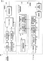
- FIG. 1 is a functional block diagram showing a configuration example of the base station apparatus according to this embodiment.
- the base station apparatus 100 includes a transmission unit 110, a scheduling unit 120, a reception unit 130, and an antenna 140.
- the transmission unit 110 includes a transmission information multiplexing unit 111, a modulation unit 112, a mapping unit 113, and a wireless transmission unit 114.
- the scheduling unit 120 includes a scheduling information generation unit 121 and an uplink transmission power control unit 122.
- the uplink transmission power control unit 122 includes a data signal power management unit 123 and a reference signal power management unit 124.
- the reception unit 130 includes a wireless reception unit 132, a propagation path information measurement unit 133, and a demodulation / data separation unit 131.
- the base station apparatus 100 includes a number of antennas 140 necessary for applying MIMO to the uplink.
- a data signal including various control information, information on the transmission power of the uplink data signal output from the uplink transmission power control unit 122, and information on the transmission power of the reference signal are transmitted to the transmission information multiplexing unit 111.
- the data to be transmitted to the mobile station apparatus is generated.
- uplink and downlink resource allocation information generated by the scheduling information generation unit 121 is also provided, and an output signal including these is generated.
- the output of the transmission information multiplexing unit 111 is input to the modulation unit 112 and modulated according to the scheduling information generation unit 121.
- the signal modulated by the modulation unit 112 is supplied to the mapping unit 113, and is mapped to the resource according to the designation of the scheduling information generation unit 121. For example, in the case of OFDMA, it is mapped to the frequency and time resource specified for each mobile station apparatus, and information broadcast to all mobile station apparatuses is also mapped to the appropriate frequency and time resource.
- the output of the mapping unit 113 is supplied to the wireless transmission unit 114 and converted into a form suitable for the transmission method.
- a time domain signal is generated by performing IFFT (Inverse Fast Fourier Transformation) on a frequency domain signal. If spatial multiplexing by MIMO (Multiple Input Multiple Output) is adopted, this processing is performed in this block.
- the output signal of the wireless transmission unit 114 is supplied to the antenna 140, and is transmitted to each mobile station apparatus from here.
- the scheduling unit 120 receives control information from an upper layer and performs resource allocation to each mobile station apparatus, modulation scheme, coding rate determination, and the like.
- the scheduling information generation unit 121 determines which information (control information, signal to each mobile station apparatus) including uplink and downlink is allocated to which time and frequency resource, and further modulates uplink and downlink. Control system, coding rate, etc. Based on these, downlink data mapping and uplink data control signal output management are performed.
- the uplink transmission power control unit 122 includes a data signal power management unit 123 and a reference signal power management unit.
- the control information from the higher layer and the output of the propagation path information measurement unit 133 are input, and transmission power is controlled and managed for each mobile station apparatus.
- the data signal power management unit 123 determines the power of the transmission data
- the reference signal power management unit 124 determines the power of the reference signal transmitted simultaneously with the uplink data. Thereby, the transmission power of the reference signal and the transmission power of the uplink data signal can be set to different values.
- the signal transmitted from the mobile station apparatus is received by the antenna 140 and then input to the radio reception unit 132.
- the wireless reception unit 132 receives data and a control signal, generates a digital signal corresponding to the transmission method, and outputs a first output signal. For example, in the case of an OFDM-based communication method, a signal subjected to FFT processing in units of processing time is output after analog / digital conversion of a received signal.
- the first output of the wireless reception unit 132 is input to the demodulation / data separation unit 131.
- the demodulation / data separation unit 131 is supplied with scheduling information for each mobile station apparatus managed by the scheduling information generation unit 121, that is, information on allocated resources and information on modulation schemes and coding rates. Demodulation is performed.
- FIG. 2 is a functional block diagram showing a configuration example of the mobile station apparatus according to this embodiment.
- the mobile station apparatus 200 includes a transmission unit 210, a scheduling information management unit 220, a reception unit 230, and an antenna 240.
- the transmission unit 210 includes a modulation unit 211, a reference signal generation unit 212, power control units 213-1 and 213-2, a mapping unit 214, and a wireless transmission unit 215.
- the scheduling information management unit 220 includes an uplink schedule information management unit 221 and an uplink transmission power information management unit 222.
- the uplink transmission power information management unit 222 includes a data signal power management unit 223 and a reference signal power management unit 224.
- the reception unit 230 includes a radio reception unit 231, a demodulation unit 232, a data signal transmission power control information extraction unit 233, a scheduling information extraction unit 234, a data extraction unit 235, and a reference signal transmission power control information extraction unit 236.
- the mobile station apparatus 200 includes as many antennas 240 as are necessary for applying MIMO to the uplink.
- the downlink signal transmitted by the base station apparatus and input via the antenna 240 is received by the radio reception unit 231 of the reception unit 230.
- the radio reception unit 231 of the reception unit 230 For example, if analog-to-digital conversion processing or the like is performed and an OFDM-based communication method is used, conversion to signals on time and frequency by FFT is also performed in this block.
- the output signal of the wireless reception unit 231 is input to the demodulation unit 232, and the transmitted information is demodulated and output together with propagation path estimation / compensation.
- Information regarding the demodulation method (modulation method, coding rate, etc.) and demodulation resources (time, frequency, code, etc.) at this time is supplied from the uplink schedule information management unit 221 that manages the schedule information already received from the base station apparatus. Is done.
- the output of the demodulation unit 232 is input to the data signal transmission power control information extraction unit 233, the scheduling information extraction unit 234, the data extraction unit 235, and the reference signal transmission power control information extraction unit 236.
- the data signal transmission power control information extraction unit 233 extracts and supplies the data signal transmission power control information extraction unit 233 to the data signal power management unit 223 when the reception signal includes information related to transmission power control of the data signal. This information may be explicitly notified using some number of bits, may be combined with other information and notified, or may be inferred from other information.
- the reference signal transmission power control information extraction unit 236 extracts and supplies this information to the reference signal power management unit 224 when the received signal includes information related to transmission power control of the uplink reference signal. This information may be explicitly notified using some number of bits, may be combined with other information and notified, or may be inferred from other information.
- the transmission power of the reference signal can be set to a value different from the transmission power of the data signal.
- the scheduling information extraction unit 234 is a block that extracts control information in which information indicating what information (time, frequency, etc.) is transmitted. This output is supplied to the uplink schedule information management unit 221.
- the data extraction unit 235 is a block that extracts information other than control information or control information used in an upper layer, and is output toward the upper layer.
- the types of signals received by the receiving unit 230 are not limited to those shown here, but may include processing for receiving / extracting other control information.
- the receiving unit 230 may include any control information and processing block.
- the uplink transmission power information management unit 222 includes a data signal power management unit 223 and a reference signal power management unit 224.
- the data signal power management unit 223 is a block that adjusts the transmission power of the data signal in accordance with power control information and scheduling transmitted from the base station apparatus.
- the control information is output to the power control unit 213.
- the reference signal power management unit 224 is a block that adjusts the transmission power of the reference signal transmitted simultaneously with the data signal according to the power control information and scheduling transmitted from the base station apparatus.
- the control information is output to the power control unit 213.
- the transmission unit 210 receives a data signal input from an upper layer and supplies the data signal to the modulation unit 211.
- Modulation section 211 performs modulation in accordance with schedule information (for example, modulation scheme and coding rate) provided from uplink schedule information management section 221.
- schedule information for example, modulation scheme and coding rate
- the output of the modulation unit 211 is supplied to the first power control unit 213-1, and the transmission power is determined and output according to the control by the uplink transmission power information management unit 222.
- the reference signal generation unit 212 generates a series of reference signal generation units according to the designation of the uplink schedule information management unit 221. This output is input to the second power control unit 213-2, the transmission power is determined according to the transmission power information managed by the reference signal power management unit 224, and the signal is output.
- the outputs of the first power control unit 213-1 and the second power control unit 213-2 are both supplied to the mapping unit 214 and managed by the uplink schedule information management unit 221.
- the mapping unit 214 maps to resources according to the assignment from the base station device. This output is input to the wireless transmission unit 215, and in the case of digital-to-analog conversion or an OFDM-based method, processing of converting a frequency domain signal into a time domain signal by IFFT is performed. This output is transmitted to the mobile station apparatus via the antenna 240.
- the order of the power control processing may be performed after the IFFT processing in the mapping unit 214 and the wireless transmission unit 215. It is not forgotten.
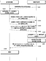
- FIG. 3 is a sequence chart showing a process and a signal flow between the base station apparatus and the mobile station apparatus in the mobile communication system of the present embodiment.
- uplink data signal communication between the mobile station apparatus and the base station apparatus in the time range of the sequence chart shown here, in the time range shown in this embodiment, spatial multiplexing by the MIMO-SM scheme is performed. Shall be done.
- the present embodiment describes the procedure between the base station apparatus and one mobile station apparatus, but the same means can be implemented when a plurality of mobile station apparatuses communicate with the base station apparatus. .
- the mobile station device transmits a propagation path measurement signal to the base station device (S301).
- the base station apparatus determines the transmission power of the reference signal and the data signal in consideration of path loss, fading, shadowing, and the like (S302).
- the mobile station apparatus may perform transmission power using only one propagation path measurement signal, or may use a plurality of propagation path measurement signals. It doesn't matter. Further, information that can be measured by other base station apparatuses, for example, interference power from mobile station apparatuses belonging to other base station apparatuses may be used.
- the base station apparatus transmits information indicating the transmission power of the data signal used for a long time to the mobile station apparatus (S303).
- information indicating the transmission power of the reference signal used for a long time is transmitted to the mobile station apparatus (S304).
- These may be controlled at higher levels than Layer 1 such as MAC (Medium Access Control) and RRC (Radio Resource Control). Further, the transmission order and the number of transmissions of these control signals may be repeated any number of times.
- Layer 1 such as MAC (Medium Access Control) and RRC (Radio Resource Control).
- the transmission order and the number of transmissions of these control signals may be repeated any number of times.
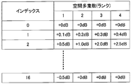
- As specific transmission power information transmission it is possible to specify a relative numerical value from the current transmission power setting value or to specify absolute power. Further, as shown in FIG.
- the power is changed according to the number of sequence multiplexing in spatial multiplexing (herein referred to as “rank”), which is a table shared in advance by the mobile station apparatus and the base station apparatus.
- rank is a table shared in advance by the mobile station apparatus and the base station apparatus.
- a method may be used in which only an index indicating an element is transmitted. Further, the procedure performed in S304 is not necessarily performed, and in that case, a value (or index) determined in advance by the base station apparatus and the mobile station apparatus may be used.
- the transmission power is determined including other information, for example, the allocated bandwidth, the type of information to be transmitted, and QoS (Quality of Service), and can be set as a relative offset value. Furthermore, when using a sequence having excellent PAPR characteristics based on OFDMA for data signal transmission and SC-FDMA for a reference signal, it is possible to provide a power difference in consideration of the difference in the method. .
- long-term means that the transmission frequency is lower than the transmission power control signal transmitted in S305, and a specific transmission cycle or timing is not determined.
- the mobile station apparatus that has received the signal of S303 or S304 may transmit an acknowledgment to the base station apparatus.
- this power setting information may be transmitted individually for each mobile station device, and is notified to a group composed of a plurality of mobile station devices and all mobile station devices belonging to the base station device. Also good. As a result, optimal power setting can be performed in consideration of flexibility and overhead of signal transmission.
- the base station apparatus transmits information on uplink resource allocation to the mobile station apparatus.
- This information includes information on resources used in the uplink, that is, information on the modulation scheme, coding rate, whether to perform MIMO-SM, and at what rank spatial multiplexing is performed at that time It is.
- information for correcting the transmission power of the data signal and the reference signal determined by the control of S303 and S304 is also given and transmitted to the mobile station apparatus (S305).
- the mobile station apparatus that has received this generates a data signal and a reference signal to be transmitted to the base station apparatus (S306), and performs power setting according to S303, S304, and S305 (S307).
- the data signal and the reference signal generated by this procedure are transmitted to the base station apparatus according to the resources allocated in S305.
- propagation path correction and demodulation are performed according to these power settings (S309).
- FIG. 5 is a sequence chart showing a process and a signal flow between the base station apparatus and the mobile station apparatus in the mobile communication system according to the present embodiment.
- the uplink data signal communication between the mobile station apparatus and the base station apparatus in the time range of the sequence chart shown here, in the time range shown in this embodiment, spatial multiplexing by the MIMO-SM scheme is performed. Shall be done.
- this embodiment has described the procedure between the base station apparatus and one mobile station apparatus, the same means can be implemented when a plurality of mobile station apparatuses communicate with the base station apparatus. Further, the configurations of the base station apparatus and the mobile station apparatus can be those shown in FIGS. 1 and 2, respectively.
- the difference from the first embodiment is that information (S303) indicating the transmission power of the data signal used for a long time transmitted from the base station device to the mobile station device, and the transmission power of the reference signal used for a long time. (S304) is transmitted as one signal (S503). That is, the transmission power of the data signal and the transmission power of the reference signal are given as offsets, and these are reported as a pair to the mobile station apparatus.
- This notification may be performed at a higher level than Layer 1 such as MAC (Medium Access Control) or RRC (Radio Resource Control), and the transmission order and number of transmissions of these control signals may be repeated any number of times. good.
- the power is changed according to the number of multiplexed sequences in space multiplexing (herein referred to as “rank”), and only the index indicating one element of the table shared in advance by the mobile station device and the base station device is transmitted.
- the method may be used. This can also be changed according to the modulation scheme, for example, QPSK, 16QAM, 64QAM.
- the transmission power is determined including other information, for example, the allocated bandwidth, the type of information to be transmitted, and QoS (Quality of Service), and can be set as a relative offset value.
- the transmission power of the data signal and the transmission power of the reference signal can be set at the same time, the number of data transmission bits required for the setting can be reduced, and the overhead can be reduced.
- FIG. 6 is a sequence chart showing a process and a signal flow between the base station apparatus and the mobile station apparatus in the mobile communication system according to the present embodiment.
- the uplink data signal communication between the mobile station apparatus and the base station apparatus in the time range of the sequence chart shown here, in the time range shown in this embodiment, spatial multiplexing by the MIMO-SM scheme is performed. Shall be done.
- the present embodiment describes the procedure between the base station apparatus and one mobile station apparatus, but the same means can be implemented when a plurality of mobile station apparatuses communicate with the base station apparatus. . Further, the configurations of the base station apparatus and the mobile station apparatus can be those shown in FIGS.
- the difference from the second embodiment is that information regarding the absolute power of the reference signal or the power difference between the data signal and the reference signal is transmitted from the base station apparatus to the mobile station according to the number of MIMO-SM spatial multiplexing sequences (rank). The device is not notified. Then, when the mobile station apparatus is notified of information about the rank transmitted simultaneously with the uplink resource allocation (S305), the absolute power of the reference signal or the power difference between the data signal and the reference signal is determined. It is to be set by the base station apparatus.
- the processing from S301 to S307 is the same as in the second embodiment.
- the mobile station apparatus uses the number of spatially multiplexed sequences (rank) notified from the base station apparatus in the process of S305 to transmit the transmission power of the reference signal. Is determined (S601). This is defined by, for example, a specification between the mobile station apparatus and the base station apparatus, and is uniquely determined by both ranks.
- the data signal and the reference signal generated by the processing of S306 are set to transmission power by the processing of S307 and S601, and are transmitted to the base station apparatus (S308).
- the number of data transmission bits required for setting can be reduced, and overhead can be reduced. it can.
- FIG. 7 is a sequence chart showing a process and a signal flow between the base station apparatus and the mobile station apparatus in the mobile communication system according to the present embodiment.
- the uplink data signal communication between the mobile station apparatus and the base station apparatus in the time range of the sequence chart shown here, in the time range shown in this embodiment, spatial multiplexing by the MIMO-SM scheme is performed. Shall be done.
- the present embodiment describes the procedure between the base station apparatus and one mobile station apparatus, but the same means can be implemented when a plurality of mobile station apparatuses communicate with the base station apparatus. . Further, the configurations of the base station apparatus and the mobile station apparatus can use those shown in FIGS.
- the difference from the second embodiment is that, when two or more base station apparatuses share information on interference of reference signals between the base station apparatuses, and the power can be reduced, the mobile station apparatus serving as an interference source Is configured to reduce the power of the reference signal transmitted.
- the mobile station devices A and B transmit propagation path measurement signals to the base station devices A and B, respectively (S701). However, the signal from the mobile station apparatus A is observed as an interference signal in the base station apparatus B (S702). Receiving this, base station apparatus B calculates interference power (S703), and notifies mobile station apparatus A that it is receiving interference (S704). At this time, the base station apparatus B may notify the mobile station apparatus A that the mobile station apparatus belonging to the base station apparatus increases the transmission power of the reference signal for transmission.
- the base station apparatus A that has received S704 determines the transmission power of the reference signal and the data signal in consideration of this information, path loss, fading, shadowing, and the like (S705). At this time, the mobile station apparatus may perform transmission power using only one propagation path measurement signal, or may use a plurality of propagation path measurement signals. I will not. Further, information that can be measured by other base station apparatuses, for example, interference power from mobile station apparatuses belonging to other base station apparatuses may be used. Similar processing is also performed in the base station apparatus B.
- Information on the determined transmission power of the data signal and the reference signal is notified from the base station apparatuses A and B to the mobile station apparatuses A and B, respectively. At this time, processing is performed in which the transmission power of the reference signal in mobile station apparatus B is increased and the transmission power of the reference signal in mobile station apparatus A is decreased.
- the transmission power is set according to the notification from the base station apparatus. However, when the maximum transmission power is set in the mobile station apparatus, No power exceeding that value will be set.
- base station apparatus 110 transmission unit 111 transmission information multiplexing unit 112 modulation unit 113 mapping unit 114 wireless transmission unit 120 scheduling unit 121 scheduling information generation unit 122 uplink transmission power control unit 123 data signal power management unit 124 reference signal power management unit 130 Reception unit 131 Demodulation / data separation unit 132 Radio reception unit 133 Propagation path information measurement unit 140 Antenna 200 Mobile station apparatus 210 Transmission unit 211 Modulation unit 212 Reference signal generation units 213-1 and 213-2 Power control unit 214 Mapping unit 215 Radio Transmission unit 220 Scheduling information management unit 221 Uplink schedule information management unit 222 Uplink transmission power information management unit 223 Data signal power management unit 224 Reference signal power management unit 230 Reception unit 231 Radio reception unit 232 Demodulation unit 233 Data signal transmission power control information extraction unit 234 scheduling information extracting section 235 data extraction unit 236 reference signal transmission power control information extraction section 240 antenna
Landscapes
- Engineering & Computer Science (AREA)
- Computer Networks & Wireless Communication (AREA)
- Signal Processing (AREA)
- Mobile Radio Communication Systems (AREA)
Abstract
MIMO-SMの特性を向上させると共に、他の通信制御装置に対して与える干渉を減少させる。通信端末装置から受信した信号に基づいて、通信端末装置の送信電力を制御する通信制御装置であって、通信端末装置から伝搬路推定に用いる参照信号を受信する受信部130と、通信端末装置が参照信号を送信する際の送信電力を決定すると共に、通信端末装置がデータ信号を送信する際の送信電力を決定する上りリンク送信電力制御部122と、決定された各送信電力を示す情報を通信端末装置へ送信する送信部110と、を備える。上りリンク送信電力制御部122は、通信端末装置で空間多重されるデータ信号の系列数または通信端末装置で空間多重されるデータ信号の変調方式に応じて、通信端末装置が、参照信号を送信する際の送信電力およびデータ信号を送信する際の送信電力を決定する。
Description
本発明は、上りリンクの送信電力を制御する技術に関する。
3GPP(3rd Generation Partnership Project)は、W-CDMA(Wideband-Code Division Multiple Access)とGSM(Global System for Mobile Communications)を発展させたネットワークを基本とした携帯電話システムの仕様の検討・作成を行なうプロジェクトである。3GPPでは、第3世代無線アクセス技術の進化(Evolved Universal Terrestrial Radio Access:以下、「E-UTRA」と呼称する。)の標準化についての検討が進められており、さらに、E-UTRAを拡張してさらなる高速化・低遅延化を図るAdvanced E-UTRAについても検討が行なわれている。
E-UTRAの上りリンクでは、アクセス方式にピーク対平均電力比(PAPR:Peak to Average Power Ratio)特性に優れたDFT-S-OFDM(Discrete Fourier Transformation Spread OFDM若しくはSC(Single Carrier)-FDMAとも呼称される。)方式が採用されている。さらに、Advanced E-UTRAでは、OFDMA(Orthogonal Frequency Division Multiple Access)方式や複数のDFT-S-OFDMを同時に送信するN×DFT-S-OFDM方式の採用が検討されている。
また、これらの方式と同時に各移動局装置の伝搬路状況に応じて、MCS(Modulation Coding Scheme:誤り訂正の符号化率とデータ変調レベル)を切り替えるAMCS(Adaptive MCS)や、Advanced E-UTRAにおいては通信路容量を増大するために、MIMO(Multiple Input Multiple Output)を利用した空間多重(SM:Space Multiplexing)技術の適用も検討されている。
ここで、MIMO-SMの適用にあたって、送信信号系列を周波数等化、分離するために送信アンテナ・受信アンテナ間それぞれの伝搬路(チャネル)を知る必要がある。このチャネルは、送信アンテナごとに直交した推定系列(参照信号、RS:Reference Signal)を用いて推定される。Advanced E-UTRAにおいて、RSは、CAZAC(Constant Amplitude and Zero Autocorrelation)系列を利用した符号拡散多重により送信することが検討されている。CAZAC系列は、PAPRに優れているだけでなく自己相関特性にも優れており、時間領域での巡回遅延により直交した複数の系列を各論理アンテナから送信することで、それぞれの受信アンテナにおいて、送信アンテナのチャネルを分離することができる。
ここで、変調多値数やMIMO-SMにおける空間多重系列数が増加すると、チャネルの推定精度が信号検出の精度に与える影響は大きくなる。これの影響を軽減するためにはRSのSNRを向上させなければならない。これに対する技術して、2乗誤差が最小となるようにチャネル推定を行なうMMSE(Minimum Mean Square Error)を用いることも提案されている。これにより、チャネル推定の誤差がデータの復調に与える影響を小さくすることが可能であるが、変調多値数が増加するほど(たとえば、16QAM、64QAM)、若しくはMIMO-SMによる空間多重数が増加するほど、チャネル推定誤差が信号検出の精度に与える影響は大きくなるため、MMSEのみでは十分な特性が得られない状況も発生する。
一方E-UTRAの上りリンクでは、他の基地局への干渉となることを避けるための電力制御が行なわれている。これは、所望の通信を行なうのに必要十分な電力を移動局装置が出力し、他の基地局への干渉となるような余分な電力を放射しないようにする制御である。
さらに、非特許文献3では、ランダムアクセス用途、サウンディング用途など、信号の種類によって電力の制御法を変えることや、基地局装置間での干渉電力を考慮した電力制御を行なうことが提案されている。
http://www.jpo.go.jp/shiryou/s_sonota/hyoujun_gijutsu/mimo/3-4-1.pdf#page=3
3GPP TS 36.213 V8.4.0 (2008-9), 3rd Generation Partnership Project; Technical Specification Group Radio Access Network; Evolved Universal Terrestrial Radio Access (E-UTRA);Physical layer procedures (Release 8)
R1-070108, "Transmission Power Control in E-UTRA Uplink", 3GPP TSG RAN WG1 Meeting #47bis, Sorrento, Italy, January 15 - 19, 2007
上記の非特許文献2のように、E-UTRAにおける仕組みにおいて、MIMO通信時に送信電力を増加させるような制御を行なうことが可能である。しかしながら、対象となる移動局装置において、同一のスループットを実現するために送信電力を増加させることは、他の基地局装置の干渉になる。このため、システム全体としてのスループットの観点から考えると、送信電力を増加させることは好ましくない。一方、送信電力の増大は、移動局装置における消費電力の観点からも望ましくない。つまり、Advanced E-UTRAにおいては、E-UTRAにおける仕組みよりさらに最適化された電力制御が必要となる。
さらに、参照信号の推定誤差による特性劣化の影響は、変調方式や空間多重における同時多重系列数により変化する。復調に利用される伝搬路推定用の参照信号の電力は、それぞれの状況に適用したものに設定されることが望ましい。
本発明は、このような事情に鑑みてなされたものであり、MIMO-SMの特性を向上させると共に、他の通信制御装置に対して与える干渉を減少させることができる通信制御装置、通信端末装置および無線通信システムを提供することを目的とする。
(1)上記の目的を達成するために、本発明は、以下のような手段を講じた。すなわち、本発明の通信制御装置は、通信端末装置から受信した信号に基づいて、前記通信端末装置の送信電力を制御する通信制御装置であって、前記通信端末装置から伝搬路推定に用いる参照信号を受信する受信部と、前記通信端末装置が前記参照信号を送信する際の送信電力を決定すると共に、前記通信端末装置がデータ信号を送信する際の送信電力を決定する上りリンク送信電力制御部と、前記決定された各送信電力を示す情報を前記通信端末装置へ送信する送信部と、を備えることを特徴としている。
このように、通信端末装置が参照信号を送信する際の送信電力を決定すると共に、通信端末装置がデータ信号を送信する際の送信電力を決定するので、他の通信制御装置に対して与える干渉を低減すると共に、MIMO-SMの特性を向上させることが可能となる。
(2)また、本発明の通信制御装置において、前記上りリンク送信電力制御部は、前記通信端末装置で空間多重されるデータ信号の系列数に応じて、前記通信端末装置が前記参照信号を送信する際の送信電力を決定すると共に、前記通信端末装置がデータ信号を送信する際の送信電力を決定することを特徴としている。
このように、通信端末装置で空間多重されるデータ信号の系列数に応じて、通信端末装置が参照信号を送信する際の送信電力を決定すると共に、通信端末装置がデータ信号を送信する際の送信電力を決定するので、データ信号と参照信号の電力設定を、通信方式に応じた設定とすることができ、電力効率および誤り特性の向上を図ることが可能となる。
(3)また、本発明の通信制御装置において、前記上りリンク送信電力制御部は、前記通信端末装置で空間多重されるデータ信号の変調方式に応じて、前記通信端末装置が前記参照信号を送信する際の送信電力を決定すると共に、前記通信端末装置がデータ信号を送信する際の送信電力を決定することを特徴としている。
このように、通信端末装置で空間多重されるデータ信号の変調方式に応じて、通信端末装置が参照信号を送信する際の送信電力を決定すると共に、通信端末装置がデータ信号を送信する際の送信電力を決定するので、データ信号と参照信号の電力設定を、通信方式に応じた設定とすることができ、電力効率および誤り特性の向上を図ることが可能となる。
(4)また、本発明の通信制御装置において、前記上りリンク送信電力制御部は、前記参照信号の送信電力を、前記データ信号の送信電力のオフセット値として決定し、前記送信部は、前記決定されたオフセット値を前記通信端末装置へ送信することを特徴としている。
このように、参照信号の送信電力を、データ信号の送信電力のオフセット値として決定し、決定したオフセット値を通信端末装置へ送信するので、通信端末装置における送信電力の設定に必要となるデータ送信ビット数を削減することができ、データのオーバーヘッドを減らすことが可能となる。その結果、スループットの向上を図ることが可能となる。
(5)また、本発明の通信制御装置は、前記通信端末装置で空間多重されるデータ信号の系列数または変調方式を示す情報を前記通信端末装置へ送信することにより、前記決定した各送信電力を前記通信端末装置へ通知することを特徴としている。
このように、通信端末装置で空間多重されるデータ信号の系列数または変調方式を示す情報を通信端末装置へ送信することにより、決定した各送信電力を通信端末装置へ通知するので、参照信号の絶対的な電力値を示す情報や、データ信号と参照信号の電力差を示す情報を送信する必要がなくなる。その結果、通信端末装置における送信電力の設定に必要となるデータ送信ビット数を削減することができ、データのオーバーヘッドを減らすことが可能となる。その結果、スループットの向上を図ることが可能となる。
(6)また、本発明の通信制御装置は、管轄範囲外の通信端末装置から送信された信号が干渉信号となる場合、前記管轄範囲外の通信端末装置を管轄する他の通信制御装置に対して、干渉が発生した旨を示す情報、または管轄範囲内の通信端末装置が参照信号の送信電力を増加する旨を示す情報を送信することを特徴としている。
このように、管轄範囲外の通信端末装置から送信された信号が干渉信号となる場合、前記管轄範囲外の通信端末装置を管轄する他の通信制御装置に対して、干渉が発生した旨を示す情報、または管轄範囲内の通信端末装置が参照信号の送信電力を増加する旨を示す情報を送信するので、通信制御装置間における干渉を考慮して、柔軟で最適なデータ通信を実現させることが可能となる。
(7)また、本発明の通信制御装置は、他の通信制御装置から、干渉が発生した旨を示す情報、または前記他の通信制御装置の管轄範囲内の通信端末装置が参照信号の送信電力を増加する旨を示す情報を受信した場合、管轄範囲内の通信端末装置が参照信号を送信する際の送信電力を減少させることを特徴としている。
このように、他の通信制御装置から、干渉が発生した旨を示す情報、または他の通信制御装置の管轄範囲内の通信端末装置が参照信号の送信電力を増加する旨を示す情報を受信した場合、管轄範囲内の通信端末装置が参照信号を送信する際の送信電力を減少させるので、通信制御装置間における干渉を考慮して、柔軟で最適なデータ通信を実現させることが可能となる。
(8)また、本発明の通信端末装置は、通信制御装置から送信電力の制御を受ける通信端末装置であって、前記通信制御装置から、送信電力を示す制御情報を受信する端末側受信部と、前記制御情報から、伝搬路推定に用いる参照信号を送信する際の送信電力およびデータ信号を送信する際の送信電力を抽出する上りリンク送信電力情報管理部と、参照信号およびデータ信号をそれぞれに定められた送信電力で前記通信制御装置へ送信する送信部と、を備えることを特徴としている。
このように、制御情報から、伝搬路推定に用いる参照信号を送信する際の送信電力およびデータ信号を送信する際の送信電力を抽出し、参照信号およびデータ信号をそれぞれに定められた送信電力で通信制御装置へ送信するので、他の通信制御装置に対して与える干渉を低減すると共に、MIMO-SMの特性を向上させることが可能となる。
(9)また、本発明の無線通信システムは、上記のいずれかに記載の通信制御装置と、上記の通信端末装置と、から構成されることを特徴としている。
この構成により、通信端末装置が参照信号を送信する際の送信電力を決定すると共に、通信端末装置がデータ信号を送信する際の送信電力を決定するので、他の通信制御装置に対して与える干渉を低減すると共に、MIMO-SMの特性を向上させることが可能となる。
本発明によれば、通信端末装置が参照信号を送信する際の送信電力を決定すると共に、通信端末装置がデータ信号を送信する際の送信電力を決定するので、他の通信制御装置に対して与える干渉を低減すると共に、MIMO-SMの特性を向上させることが可能となる。
以下、本発明の実施形態による通信技術について、図面を参照しながら説明する。なお、以下の説明において、本発明を移動通信システムに具現化する場合について説明するが、これに限定されるものではない。例えば、移動通信方法なども本発明の範疇に入るものである。また、本実施形態において、基地局装置は、通信制御装置を構成し、移動局装置は、通信端末装置を構成する。また、通信端末装置は、移動するものに限られない。
(第1の実施形態)
本発明の第1の実施形態による移動通信システムは、基地局装置と移動局装置とから構成される。図1は、本実施形態に係る基地局装置の一構成例を示す機能ブロック図である。図1に示すように、基地局装置100は、送信部110、スケジューリング部120、受信部130、アンテナ140を備えている。
本発明の第1の実施形態による移動通信システムは、基地局装置と移動局装置とから構成される。図1は、本実施形態に係る基地局装置の一構成例を示す機能ブロック図である。図1に示すように、基地局装置100は、送信部110、スケジューリング部120、受信部130、アンテナ140を備えている。
送信部110は、送信情報多重部111、変調部112、マッピング部113および無線送信部114を備えている。スケジューリング部120は、スケジューリング情報生成部121、上りリンク送信電力制御部122から構成される。上りリンク送信電力制御部122は、データ信号電力管理部123および参照信号電力管理部124を備えている。受信部130は、無線受信部132、伝搬路情報測定部133、復調・データ分離部131を備えている。また、基地局装置100は、上りリンクにMIMOを適用するために必要な数のアンテナ140を備えている。
送信部110において、各種制御情報を含むデータ信号と、上りリンク送信電力制御部122から出力される上りリンクデータ信号の送信電力に関する情報、および参照信号の送信電力に関する情報は、送信情報多重部111に入力され、移動局装置に送信するデータが生成される。さらに、スケジューリング情報生成部121が生成する上りリンク、下りリンクのリソース割り当て情報も提供され、これらを含めた出力信号が生成される。
送信情報多重部111の出力は、変調部112に入力され、スケジューリング情報生成部121に従った変調が施される。変調部112により変調された信号は、マッピング部113に供給され、スケジューリング情報生成部121の指定に従ったリソースにマッピングが行なわれる。例えば、OFDMAであれば、移動局装置ごとに指定された周波数、時間リソースにマッピングされ、全移動局装置に報知される情報なども然るべき周波数、時間リソースにマッピングされる。
マッピング部113の出力は、無線送信部114に供給され、送信方式にあった形態に変換される。例えば、OFDMAベースの通信方式であれば、周波数領域の信号に対してIFFT(Inverse Fast Fourier Transformation)が施されることにより、時間領域の信号が生成される。また、MIMO(Multiple Input Multiple Output)による空間多重が採用されていれば、この処理がこのブロックにて行なわれる。無線送信部114の出力信号は、アンテナ140に供給され、ここから各移動局装置へ送信される。
スケジューリング部120は、上位レイヤからの制御情報を受け取り、各移動局装置へのリソース割り当てや変調方式、符号化率の決定などを行なっている。特に、スケジューリング情報生成部121は、上り、下りを含めてどの情報(制御情報、各移動局装置への信号)をどの時間、周波数リソースに配置するか、さらには、上りリンク、下りリンクの変調方式、符号化率などを制御する。そして、これらを基にした下りリンクデータのマッピングや上りリンクデータの制御信号の出力管理を行なう。
上りリンク送信電力制御部122は、データ信号電力管理部123と参照信号電力管理部から構成される。上位レイヤからの制御情報と伝搬路情報測定部133の出力を入力として、移動局装置ごとの送信電力の制御および管理を行なう。データ信号電力管理部123は、送信データの電力を決定し、参照信号電力管理部124は上りリンクデータと同時に送信される参照信号の電力を決定する。これにより、参照信号の送信電力と上りリンクデータ信号の送信電力とをそれぞれ異なる値とすることができる。
移動局装置から送信された信号は、アンテナ140で受信された後、無線受信部132に入力される。無線受信部132は、データや制御信号を受け取り、送信方式に応じたディジタル信号を生成して第1の出力信号を出力する。例えば、OFDMベースの通信方式であれば、受信信号をアナログ・ディジタル変換した後、処理時間単位でFFT処理を施した信号が出力される。
無線受信部132の第1の出力は、復調・データ分離部131に入力される。復調・データ分離部131には、スケジューリング情報生成部121で管理されている移動局装置ごとのスケジューリング情報、つまり、割り当てられたリソースの情報や変調方式と符号化率に関する情報が供給され、これを利用した復調が行なわれる。
さらに、この復調を行なう際には、フェージングを補償する必要があるが、伝搬路は上りリンクデータと同時に送信される参照信号が利用される。ここで、参照信号とデータ信号の電力が差分を持って設定されている可能性があるため、データ信号電力管理部123および参照信号電力管理部124で管理する電力情報を用いてこれを補償する。送信信号が空間多重されている場合には、系列の分離もこの処理にて同時に行なわれる。
図2は、本実施形態に係る移動局装置の一構成例を示す機能ブロック図である。図2に示すように、移動局装置200は、送信部210、スケジューリング情報管理部220、受信部230、アンテナ240を備えている。送信部210は、変調部211、参照信号生成部212、電力制御部213-1、213-2、マッピング部214、無線送信部215を備えている。スケジューリング情報管理部220は、上りリンクスケジュール情報管理部221、上りリンク送信電力情報管理部222を備える。上りリンク送信電力情報管理部222は、データ信号電力管理部223、参照信号電力管理部224を備えている。
受信部230は、無線受信部231、復調部232、データ信号送信電力制御情報抽出部233、スケジューリング情報抽出部234、データ抽出部235、参照信号送信電力制御情報抽出部236を備えている。また、移動局装置200は、上りリンクにMIMOを適用するために必要な数のアンテナ240を備えている。
基地局装置によって送信され、アンテナ240を経由して入力された下りリンク信号は、受信部230の無線受信部231で受信される。例えば、アナログ・ディジタル変換の処理などがこれに当たり、OFDMベースの通信方式が利用されていれば、FFTによる時間・周波数上の信号への変換についてもこのブロックで実施される。
無線受信部231の出力信号は、復調部232へ入力され、伝搬路推定・補償とともに送信された情報の復調が行なわれて出力される。このときの復調方法(変調方式、符号化率など)や復調リソース(時間、周波数、符号など)に関する情報は、すでに基地局装置から受信したスケジュール情報を管理する上りリンクスケジュール情報管理部221から供給される。
復調部232の出力は、データ信号送信電力制御情報抽出部233、スケジューリング情報抽出部234、データ抽出部235、参照信号送信電力制御情報抽出部236に入力される。データ信号送信電力制御情報抽出部233は、受信信号にデータ信号の送信電力制御に関する情報が含まれていた場合、これを抽出してデータ信号電力管理部223に供給する。この情報は何ビットかを利用して明示的に通知されてもよく、他の情報と結合されて通知され、または他の情報から類推されるという形式が採られても良い。参照信号送信電力制御情報抽出部236も同様に、受信信号に、上りリンク参照信号の送信電力制御に関する情報が含まれていた場合、これを抽出して参照信号電力管理部224に供給する。この情報は何ビットかを利用して明示的に通知されてもよく、他の情報と結合されて通知され、若しくは他の情報から類推されるという形式が採られても良い。
参照信号の送信電力は、データ信号の送信電力と異なる値が設定可能である。スケジューリング情報抽出部234は、どのリソース(時間、周波数など)にてどのような情報が送られるかという情報が記載された制御情報を抽出するブロックである。この出力は、上りリンクスケジュール情報管理部221に供給される。データ抽出部235は、制御情報以外の情報、若しくは上位のレイヤで利用される制御情報を抽出するブロックであり、上位レイヤに向けて出力される。
ただし、受信部230が受信する信号の種類は、ここで示されたものだけではなく、その他の制御情報を受信・抽出する処理が含まれることもある。受信部230には、どのような制御情報と処理ブロックが含まれても良い。
上りリンク送信電力情報管理部222は、データ信号電力管理部223と参照信号電力管理部224とを備えている。データ信号電力管理部223は、基地局装置から送信された電力制御情報やスケジューリングに従って、データ信号の送信電力の調整を行なうブロックである。制御情報は、電力制御部213へ出力される。参照信号電力管理部224は、基地局装置から送信された電力制御情報やスケジューリングに従って、データ信号と同時に送信される参照信号の送信電力の調整を行なうブロックである。制御情報は電力制御部213へ出力される。
送信部210は、上位レイヤから入力されるデータ信号が入力され、変調部211へ供給される。変調部211は、上りリンクスケジュール情報管理部221から提供されるスケジュール情報(例えば、変調方式、符号化率)に従って変調を行なう。変調部211の出力は、第1の電力制御部213-1へ供給され、上りリンク送信電力情報管理部222による制御に従い、送信電力が決定され出力される。
参照信号生成部212は、上りリンクスケジュール情報管理部221の指定に従った系列の参照信号生成部を発生する。この出力は、第2の電力制御部213-2に入力され、参照信号電力管理部224が管理する送信電力情報に従って送信電力が決定されて、その信号が出力される。
第1の電力制御部213-1と第2の電力制御部213-2の出力は、ともにマッピング部214に供給され、上りリンクスケジュール情報管理部221にて管理される。マッピング部214は、基地局装置からの割り当てに従ったリソースにマッピングする。この出力は、無線送信部215へ入力され、ディジタル・アナログ変換や、OFDMベースの方式であれば、周波数領域の信号をIFFTにより時間領域の信号に変換する処理を行なう。これの出力は、アンテナ240を介して移動局装置に送信される。
なお、電力制御部213-1、213-2の制御について、その電力制御を行なう処理の前後関係は、マッピング部214、無線送信部215におけるIFFT処理の後に行なわれてもよく、その順序は問われないものである。
図3は、本実施形態の移動通信システムにおける基地局装置と移動局装置との間の処理および信号の流れを示すシーケンスチャートである。ここで示されたシーケンスチャートの時間範囲において、移動局装置と基地局装置間での上りリンクデータ信号の通信について、本実施形態で示された時間範囲においては、MIMO-SM方式による空間多重が行なわれるものとする。本実施形態は、基地局装置と1つの移動局装置との間の手続きについて説明しているが、複数の移動局装置が基地局装置と通信する場合にも同様の手段を実施することができる。
移動局装置は、基地局装置に対して、伝搬路測定用の信号を送信する(S301)。これを受信した基地局装置は、パスロス、フェージングやシャドウイングなどを考慮して参照信号とデータ信号の送信電力を決定する(S302)。このとき、移動局装置は、ひとつの伝搬路測定用の信号のみを利用した送信電力を行なうことも、複数の伝搬路測定用の信号を利用してもよく、具体的な方法についてはここでは問われない。また、その他の基地局装置が計測することができる情報、たとえば他の基地局装置に属する移動局装置からの干渉電力を利用しても良い。
次に、基地局装置は長期的に利用するデータ信号の送信電力を示す情報を移動局装置に送信する(S303)。これと共に、長期的に利用する参照信号の送信電力を示す情報を移動局装置に送信する(S304)。これらはMAC(Medium Access Control)やRRC(Radio Resource Control)などのレイヤ1より上位での制御を行なっても良い。また、これらの制御信号の送信順序および送信回数は何回繰り返されても良い。具体的な送信電力情報の送信として、現在の送信電力設定値からの相対的な数値を指定することも、絶対的な電力を指定することも可能である。また、その電力は、図4に示すように、空間多重における系列多重数(ここでは「ランク」と呼称する。)によって変化させ、それを移動局装置、基地局装置であらかじめ共有した表の一要素を指すインデックのみを送信する方式でも良い。また、S304で行われた手順は必ず行われる必要はなく、その場合には基地局装置と移動局装置であらかじめ決められた値(若しくはインデックス)が利用されてもよい。
これは変調方式、例えば、QPSK、16QAM、64QAMに応じて変化させることもできる。さらに、送信電力は他の情報、例えば、割り当て帯域幅、送信する情報の種類、QoS(Quality of Service)も含めて決定され、これに対する相対的なオフセット値として設定されることも可能である。さらには、データ信号の送信にOFDMA、参照信号にSC-FDMAをベースとしたPAPR特性に優れた系列を利用する場合には、その方式の違いを考慮した電力差を持たせることも可能である。
ここで、長期的とは、S305で送信される送信力制御の信号より送信頻度が低いことを表しており、具体的な送信周期やタイミングが決められたものではない。さらに、ここでは送信を正しく受信できたか否かを示す信号は記載していないが、S303やS304の信号を受け取った移動局装置が、確認応答を基地局装置に送信しても良い。さらに、この電力設定情報は、移動局装置ひとつずつ個別に送信してもよく、複数の移動局装置から構成されるグループや、基地局装置に所属する全ての移動局装置に対して報知しても良い。これにより、柔軟性と信号送信のオーバーヘッドを考慮した最適な電力設定を行なうことができる。
次に、基地局装置は、移動局装置に対しての上りリンクリソースの割り当てに関する情報を送信する。この情報には、上りリンクで利用するリソースに関する情報、つまり、変調方式、符号化率、MIMO-SMをするか否か、またその時にはいくつのランクにて空間多重を行なうか、という情報が含まれている。これに加え、S303、S304の制御により決定されたデータ信号および参照信号の送信電力を補正するための情報も付与されて移動局装置に送信される(S305)。これを受信した移動局装置は、基地局装置に送信するためのデータ信号と参照信号を発生させ(S306)、S303、S304、S305に従った電力設定を行なう(S307)。この手順により生成されたデータ信号と参照信号は、S305によって割り当てられたリソースに従って基地局装置に送信される。基地局装置では、これらの電力設定に従った伝搬路補正および復調が行なわれる(S309)。
このように、上りリンク信号における空間多重を用いた信号送信において、データ信号と参照信号の電力設定を通信方式に応じた設定にすることにより、より電力効率および誤り率特性の良い通信を行なうことが可能となる。
(第2の実施形態)
図5は、本実施形態に係る移動通信システムにおける基地局装置と移動局装置との間の処理および信号の流れを示すシーケンスチャートである。ここで示されたシーケンスチャートの時間範囲において、移動局装置と基地局装置間での上りリンクデータ信号の通信について、本実施形態で示された時間範囲においては、MIMO-SM方式による空間多重が行なわれるものとする。本実施形態は基地局装置と1つの移動局装置との間の手続きについて説明しているが、複数の移動局装置が基地局装置と通信する場合にも同様の手段を実施することができる。また、基地局装置と移動局装置の構成は、それぞれ図1および図2に示したものを利用できる。
図5は、本実施形態に係る移動通信システムにおける基地局装置と移動局装置との間の処理および信号の流れを示すシーケンスチャートである。ここで示されたシーケンスチャートの時間範囲において、移動局装置と基地局装置間での上りリンクデータ信号の通信について、本実施形態で示された時間範囲においては、MIMO-SM方式による空間多重が行なわれるものとする。本実施形態は基地局装置と1つの移動局装置との間の手続きについて説明しているが、複数の移動局装置が基地局装置と通信する場合にも同様の手段を実施することができる。また、基地局装置と移動局装置の構成は、それぞれ図1および図2に示したものを利用できる。
第1の実施形態との違いは、基地局装置から移動局装置へと送信される長期的に利用するデータ信号の送信電力を示す情報(S303)と、長期的に利用する参照信号の送信電力を示す情報(S304)を一つの信号として送信することである(S503)。つまり、データ信号の送信電力と参照信号の送信電力は、オフセットとして与えられ、これらは対となって移動局装置に通知される。この通知は、MAC(Medium Access Control)やRRC(Radio Resource Control)などのレイヤ1より上位での制御を行なってもよく、またこれらの制御信号の送信順序および送信回数は何回繰り返されても良い。
具体的な送信電力情報の送信として、現在の送信電力設定値からの相対的な数値を指定することも、絶対的な電力を指定することも可能である。また、その電力は空間多重における系列多重数(ここでは「ランク」と呼称する。)によって変化させ、それを移動局装置、基地局装置であらかじめ共有した表の一要素を指すインデックのみを送信する方式でも良い。これは、変調方式、例えば、QPSK、16QAM、64QAMに応じて変化させることもできる。さらに、送信電力は他の情報、例えば、割り当て帯域幅、送信する情報の種類、QoS(Quality of Service)も含めて決定され、これに対する相対的なオフセット値として設定されることも可能である。さらには、データ信号の送信にOFDMA、参照信号にSC-FDMAをベースとしたPAPR特性に優れた系列を利用する場合には、その方式の違いを考慮した電力差を持たせることも可能である。その他の動作については、第1の実施形態と同様である。
このように、データ信号の送信電力と、参照信号の送信電力に関連を持たせて同時に設定できるようにすることで、設定に要するデータ送信ビット数を削減でき、オーバーヘッドを減らすことができる。
(第3の実施形態)
図6は、本実施形態に係る移動通信システムにおける基地局装置と移動局装置との間の処理および信号の流れを示すシーケンスチャートである。ここで示されたシーケンスチャートの時間範囲において、移動局装置と基地局装置間での上りリンクデータ信号の通信について、本実施形態で示された時間範囲においては、MIMO-SM方式による空間多重が行なわれるものとする。本実施形態は、基地局装置と1つの移動局装置との間の手続きについて説明しているが、複数の移動局装置が基地局装置と通信する場合にも同様の手段を実施することができる。また、基地局装置と移動局装置の構成は図1および図2に示したものを利用できる。
図6は、本実施形態に係る移動通信システムにおける基地局装置と移動局装置との間の処理および信号の流れを示すシーケンスチャートである。ここで示されたシーケンスチャートの時間範囲において、移動局装置と基地局装置間での上りリンクデータ信号の通信について、本実施形態で示された時間範囲においては、MIMO-SM方式による空間多重が行なわれるものとする。本実施形態は、基地局装置と1つの移動局装置との間の手続きについて説明しているが、複数の移動局装置が基地局装置と通信する場合にも同様の手段を実施することができる。また、基地局装置と移動局装置の構成は図1および図2に示したものを利用できる。
第2の実施形態との違いは、MIMO-SMの空間多重系列数(ランク)に応じた参照信号の絶対的な電力、若しくはデータ信号と参照信号の電力差に関する情報が基地局装置から移動局装置に通知されないことにある。そして、移動局装置から上りリンクのリソース割り当てと同時に送信されるランクに関する情報を通知されたと同時に(S305)、予め決められた参照信号の絶対的な電力、若しくはデータ信号と参照信号の電力差を基地局装置が設定することにある。
次に、基地局装置と移動局装置の電力設定の手順について、図6を用いて説明する。まず、S301からS307までの処理は、第2の実施形態と同様である。S307の処理において、データ信号の送信電力の決定を行なった後、移動局装置は基地局装置からS305の処理にて通知された、空間多重系列数(ランク)を用いて、参照信号の送信電力を決定する(S601)。これは、移動局装置と基地局装置の間で、例えば、仕様書などで定義されており、ランクによって双方で一意に決定される。S306の処理によって発生されたデータ信号と参照信号は、S307、S601の処理によって送信電力を設定され、基地局装置に送信される(S308)。
このように、データ信号の送信電力と、参照信号の送信電力の電力差をあらかじめ移動局装置と基地局装置で決定することで、設定に要するデータ送信ビット数を削減でき、オーバーヘッドを減らすことができる。
(第4の実施形態)
図7は、本実施形態に係る移動通信システムにおける基地局装置と移動局装置との間の処理および信号の流れを示すシーケンスチャートである。ここで示されたシーケンスチャートの時間範囲において、移動局装置と基地局装置間での上りリンクデータ信号の通信について、本実施形態で示された時間範囲においては、MIMO-SM方式による空間多重が行なわれるものとする。本実施形態は、基地局装置と1つの移動局装置との間の手続きについて説明しているが、複数の移動局装置が基地局装置と通信する場合にも同様の手段を実施することができる。また、基地局装置と移動局装置の構成は、図1および図2に示したものを利用できる。
図7は、本実施形態に係る移動通信システムにおける基地局装置と移動局装置との間の処理および信号の流れを示すシーケンスチャートである。ここで示されたシーケンスチャートの時間範囲において、移動局装置と基地局装置間での上りリンクデータ信号の通信について、本実施形態で示された時間範囲においては、MIMO-SM方式による空間多重が行なわれるものとする。本実施形態は、基地局装置と1つの移動局装置との間の手続きについて説明しているが、複数の移動局装置が基地局装置と通信する場合にも同様の手段を実施することができる。また、基地局装置と移動局装置の構成は、図1および図2に示したものを利用できる。
第2の実施形態との違いは、基地局装置間における参照信号の干渉に関する情報を、ふたつ以上の基地局装置が共有し、電力を下げることができる場合には、干渉源となる移動局装置が送信する参照信号の電力を下げる設定を行なうことである。
本実施形態の仕組みについて図7を用いて説明する。図7では、基地局装置Aと移動局装置Aが通信を行ない、基地局装置Bと移動局装置Bが通信を行なっているものとする。また、移動局装置Aから送信する信号が基地局装置Bに対して干渉を与えているものとし、移動局装置Bから基地局装置Aへの干渉は便宜的に存在していないものとする。
移動局装置AおよびBは、それぞれ基地局装置A、Bに対して、伝搬路測定用の信号を送信する(S701)。ただし、移動局装置Aからの信号は、基地局装置Bにおいて干渉信号として観測されている(S702)。これを受信した基地局装置Bは、干渉電力を計算し(S703)、移動局装置Aに対して干渉を受けていることを通知する(S704)。このとき、基地局装置Bは、移動局装置Aに対して自局に属する移動局装置が、参照信号の送信電力を増加させて送信するということを通知しても良い。
S704を受信した基地局装置Aは、この情報とパスロス、フェージングやシャドウイングなどを考慮して参照信号とデータ信号の送信電力を決定する(S705)。このとき、移動局装置はひとつの伝搬路測定用の信号のみを利用した送信電力を行なうことも、複数の伝搬路測定用の信号を利用してもよく、具体的な方法についてはここでは問われない。また、その他の基地局装置が計測することができる情報、たとえば他の基地局装置に属する移動局装置からの干渉電力を利用しても良い。同様の処理は基地局装置Bでも行なわれる。
決定されたデータ信号と参照信号の送信電力に関する情報は、基地局装置A、Bからそれぞれ、移動局装置A、Bへと通知される。このとき、移動局装置Bにおける参照信号の送信電力は増加され、移動局装置Aにおける参照信号の送信電力は減少されるといった処理が行なわれる。
S303からS308における処理については、第2の実施形態と同様である。ただし、S305にて割り当てられる上りリンクの時間、周波数のリソースは同一のものを利用している、つまり、移動局装置AとBともに同一か、若しくは一部が重複していることが前提となる。
以上のように、基地局装置間における干渉を考慮してデータ信号の送信電力と、参照信号の送信電力の電力差を決定することで、より柔軟かつ最適なデータ通信を行なうことが可能となる。なお、第1~第4の実施形態にて、基地局装置からの通知に従った送信電力の設定を行なうことを記載しているが、移動局装置において最大送信電力が設定される場合には、それを超えた電力の設定は行なわないこととする。
以上、本発明の各実施形態について図面を参照して詳述してきたが、具体的な構成は上記実施形態に限定されるものではなく、この発明の要旨を逸脱しない範囲の設計等も特許請求の範囲に含まれる。
100 基地局装置
110 送信部
111 送信情報多重部
112 変調部
113 マッピング部
114 無線送信部
120 スケジューリング部
121 スケジューリング情報生成部
122 上りリンク送信電力制御部
123 データ信号電力管理部
124 参照信号電力管理部
130 受信部
131 復調・データ分離部
132 無線受信部
133 伝搬路情報測定部
140 アンテナ
200 移動局装置
210 送信部
211 変調部
212 参照信号生成部
213-1、213-2 電力制御部
214 マッピング部
215 無線送信部
220 スケジューリング情報管理部
221 上りリンクスケジュール情報管理部
222 上りリンク送信電力情報管理部
223 データ信号電力管理部
224 参照信号電力管理部
230 受信部
231 無線受信部
232 復調部
233 データ信号送信電力制御情報抽出部
234 スケジューリング情報抽出部
235 データ抽出部
236 参照信号送信電力制御情報抽出部
240 アンテナ
110 送信部
111 送信情報多重部
112 変調部
113 マッピング部
114 無線送信部
120 スケジューリング部
121 スケジューリング情報生成部
122 上りリンク送信電力制御部
123 データ信号電力管理部
124 参照信号電力管理部
130 受信部
131 復調・データ分離部
132 無線受信部
133 伝搬路情報測定部
140 アンテナ
200 移動局装置
210 送信部
211 変調部
212 参照信号生成部
213-1、213-2 電力制御部
214 マッピング部
215 無線送信部
220 スケジューリング情報管理部
221 上りリンクスケジュール情報管理部
222 上りリンク送信電力情報管理部
223 データ信号電力管理部
224 参照信号電力管理部
230 受信部
231 無線受信部
232 復調部
233 データ信号送信電力制御情報抽出部
234 スケジューリング情報抽出部
235 データ抽出部
236 参照信号送信電力制御情報抽出部
240 アンテナ
Claims (9)
- 通信端末装置から受信した信号に基づいて、前記通信端末装置の送信電力を制御する通信制御装置であって、
前記通信端末装置から伝搬路推定に用いる参照信号を受信する受信部と、
前記通信端末装置が前記参照信号を送信する際の送信電力を決定すると共に、前記通信端末装置がデータ信号を送信する際の送信電力を決定する上りリンク送信電力制御部と、
前記決定された各送信電力を示す情報を前記通信端末装置へ送信する送信部と、を備えることを特徴とする通信制御装置。 - 前記上りリンク送信電力制御部は、前記通信端末装置で空間多重されるデータ信号の系列数に応じて、前記通信端末装置が前記参照信号を送信する際の送信電力を決定すると共に、前記通信端末装置がデータ信号を送信する際の送信電力を決定することを特徴とする請求項1記載の通信制御装置。
- 前記上りリンク送信電力制御部は、前記通信端末装置で空間多重されるデータ信号の変調方式に応じて、前記通信端末装置が前記参照信号を送信する際の送信電力を決定すると共に、前記通信端末装置がデータ信号を送信する際の送信電力を決定することを特徴とする請求項1記載の通信制御装置。
- 前記上りリンク送信電力制御部は、前記参照信号の送信電力を、前記データ信号の送信電力のオフセット値として決定し、
前記送信部は、前記決定されたオフセット値を前記通信端末装置へ送信することを特徴とする請求項1記載の通信制御装置。 - 前記通信端末装置で空間多重されるデータ信号の系列数または変調方式を示す情報を前記通信端末装置へ送信することにより、前記決定した各送信電力を前記通信端末装置へ通知することを特徴とする請求項1記載の通信制御装置。
- 管轄範囲外の通信端末装置から送信された信号が干渉信号となる場合、前記管轄範囲外の通信端末装置を管轄する他の通信制御装置に対して、干渉が発生した旨を示す情報、または管轄範囲内の通信端末装置が参照信号の送信電力を増加する旨を示す情報を送信することを特徴とする請求項1記載の通信制御装置。
- 他の通信制御装置から、干渉が発生した旨を示す情報、または前記他の通信制御装置の管轄範囲内の通信端末装置が参照信号の送信電力を増加する旨を示す情報を受信した場合、管轄範囲内の通信端末装置が参照信号を送信する際の送信電力を減少させることを特徴とする請求項1記載の通信制御装置。
- 通信制御装置から送信電力の制御を受ける通信端末装置であって、
前記通信制御装置から、送信電力を示す制御情報を受信する端末側受信部と、
前記制御情報から、伝搬路推定に用いる参照信号を送信する際の送信電力およびデータ信号を送信する際の送信電力を抽出する上りリンク送信電力情報管理部と、
参照信号およびデータ信号をそれぞれに定められた送信電力で前記通信制御装置へ送信する送信部と、を備えることを特徴とする通信端末装置。 - 請求項1から請求項7のいずれかに記載の通信制御装置と、
請求項8記載の通信端末装置と、から構成されることを特徴とする無線通信システム。
Applications Claiming Priority (2)
| Application Number | Priority Date | Filing Date | Title |
|---|---|---|---|
| JP2009014619 | 2009-01-26 | ||
| JP2009-014619 | 2009-01-26 |
Publications (1)
| Publication Number | Publication Date |
|---|---|
| WO2010084828A1 true WO2010084828A1 (ja) | 2010-07-29 |
Family
ID=42355882
Family Applications (1)
| Application Number | Title | Priority Date | Filing Date |
|---|---|---|---|
| PCT/JP2010/050405 Ceased WO2010084828A1 (ja) | 2009-01-26 | 2010-01-15 | 通信制御装置、通信端末装置および無線通信システム |
Country Status (1)
| Country | Link |
|---|---|
| WO (1) | WO2010084828A1 (ja) |
Cited By (2)
| Publication number | Priority date | Publication date | Assignee | Title |
|---|---|---|---|---|
| JP2012216989A (ja) * | 2011-03-31 | 2012-11-08 | Softbank Mobile Corp | 移動通信システム及び基地局装置 |
| JP2015525489A (ja) * | 2012-05-11 | 2015-09-03 | テレフオンアクチーボラゲット エル エム エリクソン(パブル) | マルチアンテナ無線通信システムにおける復調パイロットを送信する方法及び装置 |
Citations (4)
| Publication number | Priority date | Publication date | Assignee | Title |
|---|---|---|---|---|
| JP2003298510A (ja) * | 2000-06-26 | 2003-10-17 | Matsushita Electric Ind Co Ltd | 送信パワ制御方法 |
| WO2006129661A1 (ja) * | 2005-06-01 | 2006-12-07 | Matsushita Electric Industrial Co., Ltd. | 送信装置、受信装置及び送信電力制御方法 |
| WO2007146891A2 (en) * | 2006-06-13 | 2007-12-21 | Qualcomm Incorporated | Power control for wireless communication systems |
| JP2008061250A (ja) * | 2006-08-30 | 2008-03-13 | Pantech Co Ltd | 移動通信システムのセル間干渉を制御する方法 |
-
2010
- 2010-01-15 WO PCT/JP2010/050405 patent/WO2010084828A1/ja not_active Ceased
Patent Citations (4)
| Publication number | Priority date | Publication date | Assignee | Title |
|---|---|---|---|---|
| JP2003298510A (ja) * | 2000-06-26 | 2003-10-17 | Matsushita Electric Ind Co Ltd | 送信パワ制御方法 |
| WO2006129661A1 (ja) * | 2005-06-01 | 2006-12-07 | Matsushita Electric Industrial Co., Ltd. | 送信装置、受信装置及び送信電力制御方法 |
| WO2007146891A2 (en) * | 2006-06-13 | 2007-12-21 | Qualcomm Incorporated | Power control for wireless communication systems |
| JP2008061250A (ja) * | 2006-08-30 | 2008-03-13 | Pantech Co Ltd | 移動通信システムのセル間干渉を制御する方法 |
Cited By (2)
| Publication number | Priority date | Publication date | Assignee | Title |
|---|---|---|---|---|
| JP2012216989A (ja) * | 2011-03-31 | 2012-11-08 | Softbank Mobile Corp | 移動通信システム及び基地局装置 |
| JP2015525489A (ja) * | 2012-05-11 | 2015-09-03 | テレフオンアクチーボラゲット エル エム エリクソン(パブル) | マルチアンテナ無線通信システムにおける復調パイロットを送信する方法及び装置 |
Similar Documents
| Publication | Publication Date | Title |
|---|---|---|
| US8560001B2 (en) | Base station apparatus, user equipment terminal, and communication control method | |
| US8626217B2 (en) | Wireless communication system, base station apparatus and mobile station apparatus | |
| US8553795B2 (en) | Unified design and centralized scheduling for dynamic SIMO, SU-MIMO and MU-MIMO operation for RL transmissions | |
| US8494078B2 (en) | Method for transmitting data in wireless communication system | |
| CA2712460C (en) | Mobile station apparatus, base station apparatus, communication method, and communication system | |
| US20130034066A1 (en) | Radio base station apparatus, mobile terminal device and wireless communication method | |
| CN102160313B (zh) | 基站装置、用户装置和预编码方法 | |
| US11757598B2 (en) | Communications devices, infrastructure equipment and methods | |
| KR101691228B1 (ko) | 무선 통신 시스템에서 피드백 채널 전송 방법 및 장치 | |
| US20120094709A1 (en) | Wireless transmission apparatus and transmission power control method | |
| US8867459B2 (en) | Mobile subscriber information transmission over multiple uplink frames | |
| WO2010084828A1 (ja) | 通信制御装置、通信端末装置および無線通信システム | |
| WO2011052192A1 (ja) | 無線通信端末装置、無線通信基地局装置および系列番号決定方法 | |
| WO2010084821A1 (ja) | 移動通信システム、基地局装置、移動局装置および移動通信方法 | |
| WO2016029971A1 (en) | Carrier modulation in communications | |
| HK1144637B (en) | Wireless communication system, base station apparatus and mobile station apparatus |
Legal Events
| Date | Code | Title | Description |
|---|---|---|---|
| 121 | Ep: the epo has been informed by wipo that ep was designated in this application |
Ref document number: 10733435 Country of ref document: EP Kind code of ref document: A1 |
|
| NENP | Non-entry into the national phase |
Ref country code: DE |
|
| 122 | Ep: pct application non-entry in european phase |
Ref document number: 10733435 Country of ref document: EP Kind code of ref document: A1 |
|
| NENP | Non-entry into the national phase |
Ref country code: JP |