WO2010082521A1 - Mobile station apparatus, base station apparatus, handoff method, and mobile communication system - Google Patents
Mobile station apparatus, base station apparatus, handoff method, and mobile communication system Download PDFInfo
- Publication number
- WO2010082521A1 WO2010082521A1 PCT/JP2010/050074 JP2010050074W WO2010082521A1 WO 2010082521 A1 WO2010082521 A1 WO 2010082521A1 JP 2010050074 W JP2010050074 W JP 2010050074W WO 2010082521 A1 WO2010082521 A1 WO 2010082521A1
- Authority
- WO
- WIPO (PCT)
- Prior art keywords
- handover
- station apparatus
- mobile station
- base station
- reception
- Prior art date
Links
- 238000000034 method Methods 0.000 title claims description 204
- 238000010295 mobile communication Methods 0.000 title claims description 6
- 238000012545 processing Methods 0.000 claims abstract description 94
- 230000005540 biological transmission Effects 0.000 claims description 207
- 238000005259 measurement Methods 0.000 claims description 53
- 238000004891 communication Methods 0.000 claims description 22
- 230000004044 response Effects 0.000 claims description 21
- 230000002776 aggregation Effects 0.000 abstract description 91
- 238000004220 aggregation Methods 0.000 abstract description 91
- 230000000977 initiatory effect Effects 0.000 abstract 1
- 230000008569 process Effects 0.000 description 43
- 238000013507 mapping Methods 0.000 description 13
- 238000010586 diagram Methods 0.000 description 12
- 238000013468 resource allocation Methods 0.000 description 12
- 230000006870 function Effects 0.000 description 10
- 239000000969 carrier Substances 0.000 description 9
- 238000006243 chemical reaction Methods 0.000 description 7
- 102000006463 Talin Human genes 0.000 description 6
- 108010083809 Talin Proteins 0.000 description 6
- 238000002360 preparation method Methods 0.000 description 4
- 230000011664 signaling Effects 0.000 description 4
- 238000012546 transfer Methods 0.000 description 4
- 125000004122 cyclic group Chemical group 0.000 description 3
- 238000011144 upstream manufacturing Methods 0.000 description 3
- 101000741965 Homo sapiens Inactive tyrosine-protein kinase PRAG1 Proteins 0.000 description 2
- 102100038659 Inactive tyrosine-protein kinase PRAG1 Human genes 0.000 description 2
- 238000005516 engineering process Methods 0.000 description 2
- 238000012935 Averaging Methods 0.000 description 1
- 108010076504 Protein Sorting Signals Proteins 0.000 description 1
- 101100137601 Saccharomyces cerevisiae (strain ATCC 204508 / S288c) PRM8 gene Proteins 0.000 description 1
- 230000008859 change Effects 0.000 description 1
- 239000000470 constituent Substances 0.000 description 1
- 230000003247 decreasing effect Effects 0.000 description 1
- 238000013461 design Methods 0.000 description 1
- 238000001514 detection method Methods 0.000 description 1
- 239000000284 extract Substances 0.000 description 1
- 238000012986 modification Methods 0.000 description 1
- 230000004048 modification Effects 0.000 description 1
- 230000008520 organization Effects 0.000 description 1
- 230000002093 peripheral effect Effects 0.000 description 1
- 230000001360 synchronised effect Effects 0.000 description 1
Images


Classifications
-
- H—ELECTRICITY
- H04—ELECTRIC COMMUNICATION TECHNIQUE
- H04W—WIRELESS COMMUNICATION NETWORKS
- H04W36/00—Hand-off or reselection arrangements
- H04W36/0005—Control or signalling for completing the hand-off
- H04W36/0055—Transmission or use of information for re-establishing the radio link
- H04W36/0072—Transmission or use of information for re-establishing the radio link of resource information of target access point
- H04W36/00725—Random access channel [RACH]-less handover
-
- H—ELECTRICITY
- H04—ELECTRIC COMMUNICATION TECHNIQUE
- H04W—WIRELESS COMMUNICATION NETWORKS
- H04W36/00—Hand-off or reselection arrangements
- H04W36/0005—Control or signalling for completing the hand-off
- H04W36/0055—Transmission or use of information for re-establishing the radio link
- H04W36/0072—Transmission or use of information for re-establishing the radio link of resource information of target access point
Definitions
- the present invention relates to a handover technique when a mobile station apparatus receives a plurality of frequency bands simultaneously.
- EUTRA Universal Terrestrial Radio Access
- 3GPP 3rd Generation Generation Partnership Project
- EUTRA Advanced EUTRA
- LTE-Advanced LTE-Advanced
- Carrier Aggregation has been proposed as a technology that enables higher-speed data transmission while maintaining compatibility with EUTRA (for example, Non-Patent Document 2 and Non-Patent Document 3).
- Carrier Aggregation is a receiver that includes a single receiver having a reception bandwidth that exceeds the maximum transmission bandwidth of the transmission device or a plurality of receivers that have a reception bandwidth equal to the maximum transmission bandwidth of the transmission device. This is a technique for improving the data rate by receiving data of a transmitting apparatus transmitted from a plurality of different frequency bands by receivers corresponding to different frequency bands in the receiving apparatus.
- a receiving apparatus in downlink transmission is referred to as a mobile station apparatus
- a transmitting apparatus is referred to as a base station apparatus
- a receiving apparatus in uplink transmission is referred to as a base station apparatus
- a transmitting apparatus is referred to as a mobile station apparatus.
- the scope of application of the present invention need not be limited to these devices.
- the mobile station device in communication measures the reception quality of the signal transmitted from the base station device, and sequentially switches the communication to a base station device with better quality than the base station device currently in communication, It is necessary to perform a handover procedure (Non-Patent Document 4, Section 5.3.5.4). Even in the case of a mobile station device that is undergoing Carrier Aggregation, it is considered that a handover procedure is necessary from the viewpoint of continuing communication.
- W-CDMA Wideband-Code Division Multiple Access
- the mobile station apparatus simultaneously receives transmission signals (radio links, radio links) from a plurality of base station apparatuses.
- a handover procedure in a state is defined (Non-Patent Document 5, Section 8.3.5).
- Non-Patent Document 1 a method for indicating a component carrier to be changed by handover is described in Non-Patent Document 1. Is not disclosed in Non-Patent Document 4. Further, since component carriers exist in different frequency bands, the structure is different from a plurality of radio links in W-CDMA as shown in Non-Patent Document 5, and thus the same handover procedure cannot be used.
- Component Carrier also referred to as a component carrier or a carrier element
- the present invention has been made in view of such circumstances, and a mobile station device, a base station device, and a handover method capable of easily performing a handover procedure in a carrier aggregation state in which a plurality of frequency bands are received. And it aims at providing a mobile communication system.
- the mobile station apparatus of the present invention is a mobile station apparatus that receives transmission signals of a plurality of mutually different frequency bands transmitted from one or a plurality of base station apparatuses, and performs reception processing for each frequency band.
- Receive signal processing for performing control to switch a plurality of reception branches to be performed and a reception branch in operation to a reception branch corresponding to the frequency band of the handover destination indicated by the handover instruction message indicating the start of handover received from the base station apparatus A control unit, and stops the reception branch corresponding to the frequency band of the handover source indicated by the handover instruction message and operates the reception branch corresponding to the frequency band of the handover destination indicated by the handover instruction message Thus, the handover is performed.
- the active reception branch is switched to the reception branch corresponding to the frequency band to be received indicated in the handover instruction message indicating the start of handover received from the base station apparatus, a plurality of frequency bands are being received.
- the mobile station apparatus receives a plurality of frequency bands by Carrier Aggregation, it is possible to control separately a measurement report related to Carrier Aggregation and other measurement reports. As a result, unnecessary measurement results need not be transmitted to the base station apparatus, and uplink transmission resources can be used effectively.
- the mobile station apparatus of the present invention is characterized in that the frequency band corresponding to the reception branch that has received the handover instruction message is determined to be the frequency band of the handover source.
- the frequency band corresponding to the reception branch that has received the handover instruction message is determined to be the frequency band of the handover source, when the mobile station apparatus has received a plurality of frequency bands by Carrier Aggregation, the handover is performed. It becomes possible to clearly grasp the original frequency band.
- the mobile station apparatus of the present invention uses the frequency band of the handover source as a frequency band other than the frequency band corresponding to the reception branch that has received the handover instruction message based on the handover instruction message. It is characterized by judging that.
- any one frequency band other than the frequency band corresponding to the reception branch that received the handover instruction message is the frequency band of the handover source. It is possible to improve the reception success probability and the handover success probability. That is, the fact that handover is instructed means that the frequency band has a relatively poor reception quality, and therefore, there is a high probability that reception of a handover instruction message will fail in this frequency band. Therefore, for example, by transmitting a handover instruction message in another frequency band to which Carrier Aggregation is performed, it is possible to improve the reception success probability and handover success probability of the handover instruction message.
- the mobile station apparatus of the present invention is characterized in that a handover completion message indicating completion of handover is transmitted in the frequency band indicated by the handover instruction message.
- the handover completion message indicating that the handover is completed is transmitted in the frequency band indicated by the handover instruction message, the transmission probability of the handover completion message is improved, and as a result, the handover success probability is improved. It becomes possible to make it.
- the mobile station apparatus of the present invention is characterized in that a handover completion message indicating completion of handover is transmitted in the frequency band indicated by the control information included in the response of the random access channel.
- the handover completion message indicating that the handover is completed is transmitted in the frequency band indicated by the control information included in the response of the random access channel, the transmission probability of the handover completion message is improved, and as a result, the handover success probability Can be improved.
- the mobile station apparatus of the present invention is characterized in that a frequency band in which all the reception branches receive a transmission signal is determined as a frequency band of a handover source.
- the handover procedure can be simplified.
- the mobile station apparatus of the present invention determines whether or not transmission of a random access channel is necessary at the time of handover based on the handover instruction message, and as a result of the determination, transmission of a random access channel is unnecessary In this case, the random access procedure is omitted and the handover is performed. On the other hand, when the random access channel needs to be transmitted, the handover with the random access procedure is performed.
- the handover instruction message it is determined whether or not transmission of a random access channel is necessary at the time of handover, and if transmission of the random access channel is unnecessary, the random access procedure is omitted and the handover is performed.
- transmission of a random access channel is necessary, handover is performed with a random access procedure, so that it is possible to omit the random access procedure when there is no need to transmit a random access channel to establish uplink synchronization. It is possible to reduce the processing time required for the handover procedure. As a result, communication interruptions can be reduced, and communication quality can be improved. Further, by omitting the random access procedure, it is possible to reduce power consumption required at the time of handover.
- the base station apparatus of the present invention is a base station apparatus that performs radio communication with a mobile station apparatus that receives transmission signals in a plurality of different frequency bands, and indicates that a handover condition has been established. Including control information for designating a handover destination downlink frequency band and control information for designating an uplink frequency band for transmitting a handover completion message for notifying completion of handover to the mobile station apparatus that has transmitted the report message A handover instruction message indicating the start of handover is transmitted to the mobile station apparatus.
- control information specifying the downlink frequency band of the handover destination and a handover completion message notifying that the handover has been completed.
- the mobile station apparatus receives a plurality of frequency bands in the Carrier Aggregation state because a handover instruction message indicating the start of handover is transmitted to the mobile station apparatus including control information specifying the uplink frequency band to be transmitted. Even so, since it is not necessary to include information on the carrier element that stops receiving after the handover in the handover instruction message, the amount of signaling information can be reduced.
- the delivery probability of the handover completion message is improved, and the handover success probability can be improved.
- the base station apparatus of the present invention determines whether or not a random access procedure is necessary for the mobile station apparatus that has transmitted the measurement report message indicating that the handover condition is satisfied, and Based on the above, a handover instruction message indicating the start of handover including control information designating whether or not a random access procedure is necessary is transmitted to the mobile station apparatus.
- a random access procedure is determined whether or not a random access procedure is necessary for the mobile station apparatus that has transmitted the measurement report message indicating that the handover condition has been established, and based on the determination, the necessity of the random access procedure is determined. Since a handover instruction message indicating handover start is transmitted to the mobile station device including control information for specifying no, a random access procedure is performed when there is no need to transmit a random access channel in order to establish uplink synchronization. This can be omitted, and the processing time required for the handover procedure can be shortened. As a result, communication interruptions can be reduced, and communication quality can be improved. Further, in the mobile station apparatus, the power consumption required at the time of handover can be reduced by omitting the random access procedure.
- the base station apparatus of the present invention is characterized in that a random access procedure is included in a handover instruction message to notify the mobile station apparatus that a random access procedure is unnecessary.
- the mobile station device is notified that the random access procedure is unnecessary, so the mobile station device omits the random access procedure and performs high-speed handover. It becomes possible to execute.
- the base station apparatus of the present invention reserves a part of a dedicated preamble number and designates the dedicated preamble number in a handover instruction message, so that the random access procedure is unnecessary. It is characterized by notifying the station device.
- the mobile station device is notified that the random access procedure is unnecessary.
- the random access procedure can be omitted and high-speed handover can be executed.
- the base station apparatus of the present invention does not require a random access procedure by including the same frequency identifier as the frequency identifier allocated to the downlink frequency band received by the mobile station apparatus in the handover instruction message. It is characterized by notifying the mobile station apparatus of the existence.
- the mobile station apparatus is notified that the random access procedure is unnecessary.
- the random access procedure can be omitted and high-speed handover can be executed.
- the base station apparatus includes a mobile station apparatus ID that is the same as the mobile station apparatus ID used by the mobile station apparatus in a handover instruction message, so that a random access procedure is unnecessary. The mobile station apparatus is notified.
- the mobile station apparatus is notified that the random access procedure is unnecessary.
- the device can omit the random access procedure and execute a high-speed handover.
- the base station apparatus of the present invention does not require a random access procedure by designating an uplink frequency band that is the same as any of the uplink frequency bands accessed by the mobile station apparatus before the handover with the handover instruction message. This is characterized in that the mobile station apparatus is notified.
- the mobile station device is notified that the random access procedure is unnecessary by designating the same uplink frequency band as any of the uplink frequency bands accessed by the mobile station device before the handover by the handover instruction message. Therefore, the mobile station apparatus can omit the random access procedure and execute high-speed handover.
- the handover method of the present invention is a handover method for a mobile station apparatus that receives transmission signals of a plurality of different frequency bands transmitted from one or a plurality of base station apparatuses, the frequency band Among a plurality of reception branches that perform reception processing every time, an active reception branch is switched to a reception branch corresponding to the frequency band of the handover destination indicated by the handover instruction message indicating the start of handover received from the base station apparatus. Performing control, stopping the reception branch corresponding to the frequency band of the handover destination indicated in the handover instruction message, and operating the reception branch corresponding to the frequency band of the handover destination indicated in the handover instruction message, Characterized by performing handover That.
- the active reception branch is switched to the reception branch corresponding to the frequency band to be received indicated in the handover instruction message indicating the start of handover received from the base station apparatus, a plurality of frequency bands are being received.
- the mobile station apparatus receives a plurality of frequency bands by Carrier Aggregation, it is possible to control separately a measurement report related to Carrier Aggregation and other measurement reports. As a result, unnecessary measurement results need not be transmitted to the base station apparatus, and uplink transmission resources can be used effectively.
- the mobile communication system of the present invention is characterized by comprising the mobile station apparatus described in (1) above and the base station apparatus described in (8) above.
- the operating reception branch is thus switched to the reception branch corresponding to the frequency band to be received indicated in the handover instruction message indicating the start of handover received from the base station apparatus.
- Efficient handover can be realized in a state of receiving the message. For example, when the mobile station apparatus receives a plurality of frequency bands by Carrier Aggregation, it is possible to control separately a measurement report related to Carrier Aggregation and other measurement reports. As a result, unnecessary measurement results need not be transmitted to the base station apparatus, and uplink transmission resources can be used effectively.
- efficient handover can be realized in a state where a plurality of frequency bands are being received.
- 6 is a sequence chart showing a handover processing procedure of the mobile station apparatus in the first embodiment of the present invention. It is a sequence chart which shows another hand-over processing procedure of the mobile station apparatus in the 1st Embodiment of this invention. It is a flowchart which shows the process sequence of the hand-over carrier element determination process of the base station apparatus in the 1st Embodiment of this invention. 5 is a flowchart illustrating a processing procedure of a handover process of the mobile station device according to the first embodiment of the present invention. It is a sequence chart which shows the handover carrier element judgment procedure of the base station apparatus in the 2nd Embodiment of this invention.
- FIG. 21 is a sequence chart showing a hard handover procedure in the conventional W-CDMA system.
- FIG. 21 shows a mobile station apparatus, first to third base station apparatuses that use frequency band 1, and a fourth base station apparatus that uses frequency band 2. Note that the first base station device to the third base station device may be different base station devices or different transmission devices of the same base station device.
- the mobile station apparatus receives the transmission signals from the first base station apparatus to the third base station apparatus simultaneously (soft handover state, SHO state) (step S100), the first base station device A handover instruction message is notified from the station apparatus (step S101).
- the handover instruction message may be notified from the second base station apparatus or the third base station apparatus.
- the mobile station apparatus performs handover processing (step S102).
- the handover process preparations for the handover process are made based on information (handover destination base station information, handover timing, etc.) included in the handover instruction message.
- reception of transmission signals from the first base station apparatus to the third base station apparatus is stopped, and the reception frequency band is changed to the frequency band. Switch to 2.
- the mobile station apparatus establishes downlink synchronization based on the transmission signal from the fourth base station apparatus and tries to acquire uplink synchronization by transmitting a random access channel (step S103).
- the fourth base station apparatus that has received the random access channel transmits a random access response (step S104), and the mobile station apparatus that has successfully received the random access response subsequently sends a handover complete message.
- 4 is transmitted to the base station apparatus 4 to complete the handover procedure (step S105). It is possible to include a plurality of base station apparatuses in the handover instruction message, and in this case, it is possible to shift to the SHO state immediately after completion of the handover.
- FIG. 22 is a sequence chart showing a soft handover procedure in the conventional W-CDMA system.
- FIG. 22 shows a mobile station apparatus and first to fourth base station apparatuses using frequency band 1.
- the first base station device to the fourth base station device may be different base station devices or different transmission devices of the same base station device.
- the mobile station apparatus receives the transmission signals from the first base station apparatus to the third base station apparatus at the same time (soft handover state, SHO state) (step S106), the first base station A radio link update message (Active Set Update message) is notified from the station apparatus (step S107).
- the radio link update message may be notified from the second base station apparatus or the third base station apparatus. For example, when the transmission signal from the first base station apparatus is stopped in the radio link update message and the reception of the transmission signal of the fourth base station apparatus is newly instructed, the mobile station apparatus performs the radio link update process. Performed (step S108).
- radio link update process preparations for the radio link update process are made based on information included in the radio link update message (base station apparatus information for starting / stopping reception, radio link update timing, etc.). Then, at the radio link update timing notified by the radio link update message (may be immediate execution), the reception of the transmission signal of the first base station apparatus is stopped and the transmission signal of the fourth base station apparatus Is started and the SHO state is updated. Random access channel transmission is not required.
- a radio link update completion message is transmitted to the second base station apparatus to complete the radio link update procedure (step S109). Then, the start station device and the second, third, and fourth base station devices enter the SHO state (step S110). In the figure, the radio link update completion message is transmitted to the second base station apparatus. However, in actuality, any one of the second base station apparatus to the fourth base station apparatus that enters the SHO state It is only necessary to receive the update completion message, and it is not always necessary to transmit it to the second base station apparatus.
- FIG. 23 is a sequence chart showing a handover procedure in EUTRA.
- FIG. 23 shows control in which a mobile station apparatus starts from a state in which communication is performed with a first base station apparatus that is a handover source cell and is handed over to a second base station apparatus that is a handover destination cell. is there.
- the first base station apparatus to the second base station apparatus may be different base station apparatuses or different transmission apparatuses of the same base station apparatus.
- the first base station apparatus determines that the handover is necessary to continue communication
- the first base station apparatus notifies the mobile station apparatus of a handover instruction message together with the downlink resource allocation message (step S111).
- the resource indicates information such as a transmission frequency band, a transmission time, a modulation scheme, and a signal sequence.
- a handover process is performed (step S112). In the handover process, preparations for the handover process are made based on information included in the handover instruction message (handover destination base station information, random access information, etc.).
- the radio frequency and control parameters of the transmission / reception circuit are switched as necessary, and downlink synchronization establishment processing for establishing downlink radio synchronization with the second base station apparatus is performed.
- Parameters for downlink synchronization establishment processing are included in the previous handover instruction message, or are notified or notified in advance from the first base station apparatus.
- the mobile station apparatus that has completed downlink synchronization establishment transmits a random access channel to establish uplink synchronization with the second base station apparatus (step S113).
- a dedicated preamble sequence (Dedicated) is used in the handover instruction message. Preamble) is assigned to each mobile station device in advance.
- the mobile station apparatus transmits a random access channel using the dedicated preamble sequence specified in the handover instruction message, and the second base station apparatus that has received the dedicated preamble sequence has completed handover of the mobile station apparatus.
- uplink synchronization information for uplink transmission timing adjustment and uplink resource allocation information for handover completion message transmission are notified by a random access response (step S114).
- the mobile station apparatus adjusts the uplink transmission timing based on the information, transmits a handover completion message using the designated uplink resource, and completes the handover (step S115).
- FIG. 24 is a diagram illustrating how the reception frequency band is increased / decreased using Carrier Aggregation.
- Band 1 to Band 3 indicate downlink frequency bands transmitted by the base station apparatus, and the transmission bandwidth is, for example, 20 MHz.
- Band 1 to Band 3 may be continuous frequency bands or may be frequency bands in which all or part of them are discontinuous.
- the mobile station device needs to have a reception bandwidth of 20 MHz or more. In this example, up to three 20 MHz frequency bands can be received simultaneously, and the total reception bandwidth is 60 MHz.
- the mobile station apparatus communicates with the base station apparatus using 20 MHz of Band3, and simultaneously measures reception quality of Band1 to Band2. Also, at some other time Time2, Band2 is added to the mobile station apparatus, and communication is performed with the base station apparatus using a total of 40 MHz of Band2 and Band3. At the same time, the reception quality of Band1 is measured. Further, at another time Time3, Band1 is further added to the mobile station apparatus, and communication is performed with the base station apparatus using a total of 60 MHz of Band1 to Band3. Also, at some other time Time4, the mobile station apparatus deletes Band2, communicates with the base station apparatus using Band1 and Band3 in total of 40 MHz, and simultaneously measures the reception quality of Band2.
- the time length of Time 1 to Time 4 is variable.
- OFDMA Orthogonal Frequency Division Multiplexing ⁇ Access
- the OFDM symbol timing of each frequency band that is Carrier Aggregated needs to be equal. That the OFDM symbol timing is equal means that the reception delay of the OFDM symbol in each frequency band is within the guard time at the receiving antenna end of the mobile station apparatus.
- the usable frequency band is 800 MHz band, 2.4 GHz band, 3.4 GHz band
- Band 1 is 800 MHz band
- Band 2 is 2 GHz band
- Band 3 is any 20 MHz downlink component carrier. It may be transmitted by.
- each Band may be a bandwidth narrower than 20 MHz.
- the physical channel used in EUTRA and Advanced EUTRA is a physical broadcast information channel, an uplink data channel, a downlink data channel, a downlink shared control channel, an uplink shared control channel, a random access channel, a synchronization signal, and a downlink reference signal. There is an uplink reference signal.
- the physical channel may be added or changed in the future in EUTRA and Advanced EUTRA, but even if it is changed, it does not affect the description of each embodiment of the present invention.
- the physical broadcast information channel (PBCH: Physical Broadcast Channel) is transmitted for the purpose of notifying control parameters (broadcast information) that are commonly used in mobile station apparatuses in the cell.
- the broadcast information that is not notified on the physical broadcast information channel is transmitted using the downlink data channel with the transmission resource notified on the downlink shared control channel.
- Broadcast information includes a cell global ID unique to the system, uplink frequency band information, and the like.
- the downlink reference signal is a pilot signal transmitted at a predetermined power for each cell.
- the downlink reference signal is a signal that is periodically repeated at a predetermined time interval (for example, one frame), and the mobile station apparatus receives the downlink reference signal at a predetermined time interval and measures the reception quality. This is used to judge the reception quality for each cell. Further, it is used as a reference signal for demodulating downlink data transmitted simultaneously with the downlink reference signal.
- the sequence used for the downlink reference signal is a sequence that can be uniquely identified for each cell, an arbitrary sequence may be used.
- the downlink reference signal may be described as DL-RS (Downlink Reference Signal), but its use and meaning are the same.
- the downlink shared control channel (PDCCH: Physical Downlink Common Channel) is transmitted in the first few symbols of each subframe, and the resource allocation information according to the scheduling of the base station device and the transmission power adjustment amount are transmitted to the mobile station device. Used for instructional purposes.
- the mobile station apparatus needs to receive the downlink shared control channel before transmitting / receiving traffic data (user data) and control messages, acquire uplink resource allocation during transmission, and acquire downlink resource allocation information during reception.
- a random access channel (PRACH: Physical Random Access Channel) is a channel used for transmitting a preamble sequence and has a guard time.
- the random accelerator channel is used as an access procedure when the uplink transmission timing is asynchronous, and is used for adjusting resource requests and uplink transmission timing. Since other physical channels are not related to each embodiment of the present invention, detailed description thereof is omitted.
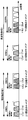
- FIG. 1A is a block diagram showing an example of a configuration of a mobile station apparatus according to the first embodiment of the present invention.
- FIG. 1B is a diagram illustrating Carrier Aggregation assumed in the present embodiment.
- the mobile station apparatus configuration is configured by a plurality of transmission / reception units in a corresponding frequency band (for example, 800 MHz band, 2.4 GHz band, 3.4 GHz band).
- FIG. 1A shows a mobile station apparatus configuration that can support the Carrier Aggregation shown in FIG. 1B.
- the reception unit corresponding to the frequency band 1 includes the reception antenna 1-1, the transmission / reception antenna duplexer DUP2-1, the radio reception unit 3-1, the orthogonal demodulator 4-1 corresponding to the downlink component carrier center frequency f_Rx1, and the baseband demodulation. Section 5-1, an orthogonal demodulator 4-2 corresponding to the downlink component carrier center frequency f_Rx2, and a baseband demodulation section 5-2.
- the reception unit corresponding to frequency band 2 includes reception antenna 1-2, transmission / reception antenna duplexer DUP2-2, radio reception unit 3-2, orthogonal demodulator 4-3 corresponding to downlink component carrier center frequency f_Rx3, base
- the band demodulator 5-3, the orthogonal demodulator 4-4 corresponding to the downlink component carrier center frequency f_Rx4, and the baseband demodulator 5-4 are configured.
- the common part includes a demapping unit 6, a transmission / reception band setting unit 8, a received signal processing control unit 10, a control message processing unit 12, a measurement processing unit 18, and a handover control unit 16.
- FIG. 1C is a diagram illustrating a detailed configuration of a radio reception unit, a quadrature demodulator, and a baseband demodulation unit, taking the direct conversion method as an example.
- FIG. 1A shows that there are a plurality of these, any configuration is the same.
- Other reception methods such as a superheterodyne method may be used.
- the receiving unit is composed of a radio receiving unit, an orthogonal demodulator, and a baseband demodulating unit.
- a downlink component carrier signal having a center frequency f_Rx1 and a frequency bandwidth of 20 MHz is transmitted from the base station apparatus, and includes a reception antenna 1-1, an LNA (Low Noise Noise) 3-1-1, an RF reception band limiting filter Rx_BPF (eg, 2 .. A filter having a 60 MHz pass band centered on a 4 GHz reception band) 3-1-2.
- LNA Low Noise Noise
- Rx_BPF eg, 2 ..
- the downlink component carrier signal having the center frequency f_Rx1 is input to the baseband demodulator through the quadrature demodulator 4-1, including the AMP 4-1-1, LPF 4-1-2, etc., and the ADC (Analog-to-Digital Converter) unit 5- 1-1a converts an analog signal into a digital signal, and a reception band-limited digital filter Rx_DF (eg, downlink component carrier signal band) 5-1-2, a cyclic prefix removal unit 5-1-3, a serial / parallel conversion unit An OFDM demodulated signal is generated through the 5-1-4, the fast Fourier transform unit 5-1-5, the synchronous detection unit 5-1-6, and the parallel / serial conversion unit 5-1-7.
- ADC Analog-to-Digital Converter
- FIG. 1A an example of a radio reception unit equal to the number of receiving antennas equal to the frequency band of the downlink component carrier and the number of carrier center frequencies of the downlink component carrier shown in FIG. 1B is shown.
- a configuration may be adopted in which a part or all of the reception antennas or radio reception units are made common due to performance, and the number of reception antennas and the number of radio reception units may be larger than the number of downlink component carriers.
- one downlink component carrier reception branch is defined for each downlink component carrier corresponding to Carrier Aggregation.
- the reception branch of the downlink component carrier f_Rx1 includes the reception antenna 1-1, the transmission / reception antenna duplexer DUP2-1, the radio reception unit 3-1, the orthogonal demodulator 4-1, the baseband demodulation unit 5- 1 is included.
- the on / off control of the reception branch means whether or not the corresponding downlink component carrier can be received, and turns on or off the functions of some or all of the devices in the reception branch depending on the hardware configuration and device configuration. . For example, in the case of FIG.
- turning off the f_Rx1 reception branch means that part or all of the functions of the orthogonal demodulator 4-1 and the baseband demodulation unit 5-1 are stopped to reduce power consumption.
- the reception signals (transmission signals from the base station apparatus) of the downlink component carriers f_Rx1 to 2 are received in the corresponding f_Rx1 and 2 reception branches via the reception antenna 1-1.
- the number of reception branches is equal to the number of frequency bands that the mobile station apparatus can simultaneously receive, that is, the number of downlink component carriers.
- Transmission / reception control information is input to the transmission / reception band setting unit 8.
- the transmission / reception control information includes a frequency band (for example, 2.4 GHz band), a downlink component carrier center frequency (for example, f_Rx1 to 2), a downlink component carrier bandwidth (for example, 20 MHz), a reception timing for each channel, and a multiplexing method. Information such as resource allocation information.
- the transmission / reception band setting unit 8 sets the frequency band to be received, the downlink component carrier center frequency, and the downlink component carrier bandwidth for each reception branch.
- the reception branch receives the set downlink component carrier signal according to the transmission / reception control information, and the signal is separated by the demapping unit 6.
- Downlink scheduling information is input to the received signal processing control unit 10.
- Downlink scheduling information includes received signal demodulation information and the like.
- the reception signal processing control unit 10 sets downlink scheduling information to the baseband demodulation units 5-1 to 5-4 of each reception branch, and the baseband demodulation units 5-1 to 5-4 of the reception branch respectively Demodulate the component carrier received signal.
- the demodulated downlink component carrier received signal is a downlink control message (layer 3 message) from an upper layer via the demapping unit 6, it is input to the control message processing unit 12. Further, the result regarding the measurement information is input to the measurement processing unit 18.
- the control message processing unit 12 receives the downlink control message from the base station apparatus, performs control processing according to the content of the downlink control message, and notifies the result to the upper layer as downlink control data.
- the downlink control message is a message related to handover (handover instruction message)
- the message is transmitted to the handover control unit 16.
- the handover control unit 16 extracts information (handover destination broadcast information, uplink / downlink channel information, etc.) used during the handover procedure from the handover instruction message, and notifies the higher layer as a handover message.
- the measurement processing unit 18 performs processing such as time averaging on the measurement result and processing such as reception quality determination, and notifies the obtained result to the upper layer as the measurement result.
- the transmission unit corresponding to frequency band 1 includes transmission antenna 1-1, transmission / reception antenna duplexer DUP2-1, radio transmission unit 13-1, orthogonal modulator 14-1 corresponding to uplink component carrier center frequency f_Tx1, baseband modulation Section 15-1, an orthogonal modulator 14-2 corresponding to the upstream component carrier center frequency f_Tx2, and a baseband modulation section 15-2.
- the transmission unit corresponding to the frequency band 2 includes a reception antenna 1-2, a transmission / reception antenna duplexer DUP2-2, a radio transmission unit 13-2, an orthogonal modulator 14-3 corresponding to the uplink component carrier center frequency f_Tx3, a base
- the band modulation unit 15-3, the quadrature modulator 14-4 corresponding to the upstream component carrier center frequency f_Tx4, and the baseband modulation unit 15-4 are configured. Further, as a common part, there are a mapping unit 7, a transmission / reception band setting unit 8, a transmission signal processing control unit 9, a random access generation unit 11, and an uplink control message generation unit 17.
- FIG. 1D is a diagram illustrating a detailed configuration of a wireless transmission unit, a quadrature modulator, and a baseband modulation unit, taking the direct conversion method as an example.
- FIG. 1A shows that there are a plurality of these, any configuration is the same.
- Other transmission methods such as a superheterodyne method may be used.
- the transmission unit is composed of a radio transmission unit, a quadrature modulator, and a baseband modulation unit.
- Transmission data (user uplink traffic data, control data, reference signal, etc.) is input to the mapping unit 7, generates predetermined uplink radio frame data, and is input to each of the baseband modulation units 15-1 to 15-4.
- the parallel conversion unit 15-1-1 performs serial / parallel data conversion, the modulation unit 15-1-1 performs phase modulation such as BPSK and QPSK by predetermined symbol coordinate conversion, and the inverse fast Fourier transform unit 15-1- 3 to convert to an OFDM signal.
- the I / Q phase OFDM signals are respectively converted by the parallel / serial converter 15-1-4 and input to the respective cyclic prefix inserters 15-1-5, where cyclic prefixes are added, and transmission band limiting is performed. It is input to the digital filter Tx_DF15-1-6 (for example, upstream component carrier signal band).
- the digital OFDM signal is converted into an analog signal by a DAC (Digital-to-Analog Converter) unit 15-1-7, and an orthogonal modulator 14-1 having an LPF 14-1-1, an AMP 14-1-2, and the like. To perform quadrature modulation.
- an uplink component carrier signal having a center frequency f_Tx1 is generated, and an RF (Radio Frequency) transmission band filter Tx_BPF 13-1-1 (for example, a filter having a 60 MHz pass band centered on a 2.4 GHz transmission band) , PA 13-1-2 (Power Amplifier), and the duplexer DUP1, the uplink component carrier signal is transmitted from the transmission shared antenna to the base station apparatus.
- the uplink component carrier of the OFDM signal is generated, but the uplink component carrier of the SC-FDMA signal may be generated with a configuration of SC-FDMA (Single-Carrier Frequency-Division Multiple Access).
- the transmission unit includes an uplink control message generation unit 17, a random access generation unit 11, a transmission signal processing control unit 9, a mapping unit 7, a transmission / reception band setting unit 8, baseband modulation units 15-1 to 15-4, an orthogonal modulator 14 -1 to 14-4, and wireless transmission units 13-1 and 13-2.
- FIG. 1A shows an example of a radio transmission unit equal to the number of transmission antennas equal to the frequency band of the uplink component carrier and the number of carrier center frequencies of the uplink component carrier shown in FIG. 1B. A configuration in which a part or all of them are shared by performance may be used, and the number of transmission antennas and the number of radio transmission units may be larger than the number of uplink component carriers.
- one uplink component carrier transmission branch is defined for each uplink component carrier corresponding to Carrier Aggregation.
- the f_Tx1 transmission branch that is the transmission branch of the uplink component carrier f_Tx1 includes the transmission antenna 1-1, the transmission / reception antenna duplexer DUP2-1, the radio transmission unit 13-1, the orthogonal modulator 14-1, and the baseband modulation unit 15-. 1 is included.
- the transmission branch on / off control means whether or not transmission of the corresponding uplink component carrier is controlled, and the functions of some or all of the devices in the transmission branch are turned on or off depending on the hardware configuration or device configuration. .
- turning off the f_Tx1 transmission branch means that part or all of the functions of the quadrature modulator 14-1 and the baseband modulation unit 15-1 are stopped to reduce power consumption.
- the uplink control message generation unit 17 receives information necessary for generating an uplink control message (layer 3 message) to be notified to the base station apparatus at an appropriate timing in accordance with an instruction from the higher layer.
- the uplink control message generation unit 17 generates each control message according to the input information, performs channel mapping by the mapping unit 7, and outputs it to the baseband modulation units 15-1 to 15-4.
- Uplink user traffic data and uplink control data included in the transmission data are channel-mapped by the mapping unit 7 and input to the baseband modulation units 15-1 to 15-4.
- random access information is input to the random access generation unit 11 and random access data is generated.
- the random access information includes preamble information and transmission resource information.
- the uplink scheduling information is input to the transmission signal processing control unit 9.
- the uplink scheduling information includes modulation information (for example, BPSK, QPSK, etc.) of transmission signals regarding each physical channel, resource block arrangement information, transmission timing, multiplexing method, and the like.
- the transmission signal processing control unit 9 sets uplink scheduling information in the baseband modulation units 15-1 to 15-4 and the mapping unit 7, and the baseband modulation units 15-1 to 15-4 Perform OFDM signal modulation.
- the component carriers generated by the baseband modulation units 15-1 to 15-4 are input to the quadrature modulators 14-1 to 14-4, and the uplink component carriers are transmitted through the radio transmission units 13-1 to 13-2. Is done.
- the transmission / reception band setting unit 8 sets the transmission frequency band (for example, 2.4 GHz band), the uplink component carrier center frequency (for example, f_Tx1 to 2), and the uplink component carrier bandwidth (for example, 20 MHz) for each transmission branch. Set.
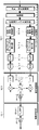
- FIG. 2 is a block diagram showing an example of the configuration of the receiving device of the base station device according to the first embodiment of the present invention.
- the receiving apparatus includes an antenna 20, a receiving unit 21, a received signal processing control unit 22, a received signal processing unit 23, an uplink message processing unit 24, a random access processing unit 25, and an inter-base station message processing unit 26.
- the reception signal (transmission signal from the mobile station apparatus) is received by the reception unit 21 via the antenna 20.
- the inter-base station received signal transmission signal from the base station apparatus
- the received signal is received based on the base station reception control information.
- the base station reception control information includes information such as reception timing, multiplexing method, and resource arrangement information regarding each channel for each mobile station apparatus.
- the reception unit 21 outputs a signal received according to the base station reception control information to the reception signal processing unit 23.
- the reception signal processing control unit 22 receives base station uplink scheduling information.
- the base station uplink scheduling information includes received signal demodulation information and the like.
- the reception signal processing control unit 22 sets uplink scheduling information in the reception signal processing unit 23.
- the received signal processing unit 23 divides the input signal for each mobile station apparatus and further demodulates appropriately for each channel.
- the input signal is an uplink message from the mobile station apparatus, it is output to the uplink message processing unit 24.
- the input signal is a random access signal acquired from a random access channel, the input signal is output to the random access processing unit 25.
- Other signals processed by the received signal processing unit 23, such as user traffic data, uplink control data, and other control messages, are input as other information to individual processing blocks. The description is omitted because it is not related to.
- the uplink message processing unit 24 acquires the control parameter included in each uplink message and outputs it to the upper layer.
- the inter-base station message processing unit 26 acquires a base station control parameter included in each inter-base station message and outputs it to the upper layer.
- the random access processing unit 25 determines the preamble sequence transmitted by the mobile station apparatus from the received random access signal, and outputs information (preamble reception quality, preamble number, etc.) obtained from the preamble sequence to an upper layer. In particular, if the preamble sequence is a dedicated preamble sequence, the mobile station apparatus determines that the access is random access during the handover procedure, and outputs the determination result to an upper layer.
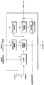
- FIG. 3 is a block diagram showing an example of the transmission apparatus of the base station apparatus according to the first embodiment of the present invention.
- This transmission apparatus includes an aggregation determination unit 31, a handover determination unit 32, a downlink message generation unit 33, a transmission signal processing unit 34, a transmission signal processing control unit 35, a channel mapping unit 36, a transmission band setting unit 37, and a transmission unit 38-1.
- an inter-base station message generator 39, and antennas 40-1 to 40-n To 38-n, an inter-base station message generator 39, and antennas 40-1 to 40-n.
- FIG. 3 shows an example in which the transmission unit and the transmission signal processing unit are equal to the number of antennas (n). There may be a configuration provided with a larger number of transmitters (transmitters) than the number of antennas.
- Measurement information is input to the handover determination unit 32 from an upper layer.
- the measurement information is information on measurement results related to the cell in communication and the neighboring cells reported from the mobile station apparatus.
- the handover determination unit 32 determines that the handover is necessary based on the measurement information, the handover determination unit 32 instructs the downlink message generation unit 33 to generate a downlink message for instructing the handover.
- the aggregation determination unit 31 inputs the mobile station device information and the measurement information, and instructs the downlink message generation unit 33 to generate a downlink message for the carrier aggregation when the carrier aggregation is necessary.
- the mobile station information includes the capability of the mobile station device and the downlink buffer amount of the mobile station device in communication.
- the downlink message generation unit 33 receives information necessary for generating a downlink message (layer 3 message) to be notified to the mobile station apparatus at an appropriate timing in accordance with an instruction from the upper layer.
- the downlink message generator 33 generates each control message according to the input information.
- the transmission signal processing unit 34 receives a downlink message, downlink data, and downlink control information.
- Base station downlink scheduling information is input to the transmission signal processing control unit 35.
- the base station downlink scheduling information includes transmission signal modulation information and the like.
- the transmission signal processing control unit 35 sets base station downlink scheduling information in the transmission signal processing unit 34, and the transmission signal processing unit 34 modulates each input data.
- the modulated data output from the transmission signal processing unit 34 based on scheduling is subjected to physical channel mapping by the channel mapping unit 36.
- the transmission band setting unit 37 sets a frequency band to be transmitted to each of the transmission units 38-1 to 38-n.
- the physical channels output from the channel mapping unit 36 are output via the antennas 40-1 to 40-n according to the frequency bands set in the transmission units 38-1 to 38-n.
- the transmission control information includes transmission timing, multiplexing method, resource allocation information and information related to each physical channel.
- the inter-base station message is input to the inter-base station message generation unit 39, and is output using a wired line such as a dedicated line as an inter-base station transmission signal.
- a wired line such as a dedicated line as an inter-base station transmission signal.
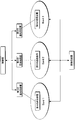
- FIG. 4A and 4B are diagrams illustrating an example of the network configuration of the present embodiment.
- a single base station apparatus has a plurality of frequency bands (Band 1) as shown in FIG. 4A. It is assumed that a transmission device (reception device) is provided for each (Band3). In addition to this, there may be a case where a base station apparatus is provided for each frequency band (Band 1 to Band 3) as shown in FIG. 4B, but there is no problem in realizing this embodiment. Naturally, the mobile station apparatus can simultaneously receive Band1 in FIG. 4A and Band2 in FIG. 4B by carrying out Carrier Aggregation.
- the base station apparatus can be managed by a higher-order control station as shown in the figure, or Carrier Aggregation may be realized by performing cooperative control between the base station apparatuses.
- Carrier Aggregation may be realized by performing cooperative control between base station apparatuses.
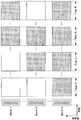
- FIG. 5 is a diagram illustrating an example of a correspondence relationship between a downlink carrier element configured and an uplink carrier element when the mobile station apparatus according to the present embodiment performs Carrier Aggregation.
- Each carrier element is composed of 20 MHz.
- the downlink carrier element DL_CC1 corresponds to the uplink carrier element UL_CC1. That is, ACK / NACK of data received by DL_CC1 and feedback of reception quality are transmitted using UL_CC1 resources. It is also possible for a plurality of downlink carrier elements to correspond to the uplink carrier element. In the example illustrated in FIG. 5, both ACK / NACK of data received by DL_CC3 and DL_CC4 and feedback of reception quality are transmitted using resources of UL_CC3.
- the mobile station device recognizes the cell as a cell without particularly being aware of which base station device the downlink carrier element is transmitted from and which base station device receives the uplink carrier element. Then, information such as the frequency band and bandwidth of the corresponding uplink carrier element is acquired from the broadcast information of the selected cell.
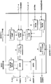
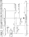
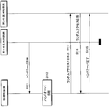
- FIG. 6 is a sequence chart showing a procedure until the base station apparatus determines the necessity of handover of the mobile station apparatus during Carrier Aggregation and notifies the handover instruction in the present embodiment.
- FIG. 6 shows a state in which a mobile station apparatus and first to fourth carrier elements are present, and the mobile station apparatus receives first to third carrier elements by Carrier Aggregation ( In the Carrier Aggregation state), the procedure for determining the necessity of handover is shown. That is, the first to third carrier elements (referred to as source cells or source carrier elements) that are handover sources use different frequency bands, and the fourth carrier element (target that is the handover destination) The cell or the target carrier element) may be in the same frequency band as any of the first to third carrier elements or in a different frequency band. However, carrier elements in the same frequency band must not be received at the same time.
- the first carrier element to the fourth carrier element may correspond to transmitters (receivers) of different base station apparatuses, or some or all of them may be different transmitters of the same base station apparatus (receiver). (Receiver) may correspond.
- the mobile station apparatus of this example is assumed to have the capability of carrying out Carrier Aggregation in at least two or more frequency bands. Actually, resource allocation by the downlink shared control channel is required prior to transmission / reception of each control message, but this is omitted in the drawings and description.
- the mobile station apparatus receives the downlink reference signal in each carrier element, and measures the downlink reception quality.
- the handover condition notified in advance from the base station apparatus is satisfied in at least one carrier element, the mobile station apparatus performs a measurement report (step S2).
- the handover conditions are, for example, (1) the downlink reception quality is below a predetermined threshold, (2) the downlink reception quality of a carrier element (target cell) that is not Carrier Aggregation is above a predetermined threshold, (3) For example, the downlink reception quality of the carrier element (target cell) that is not Carrier Aggregation exceeds the downlink reception quality of the carrier element (source cell) that is undergoing Carrier Aggregation.
- a carrier element ID (Carrier Component ID) that is a frequency band identifier is assigned to each cell from the base station apparatus. , CCID). For example, when the same CCID is allocated to the first carrier element and the second carrier element, it indicates that the first carrier element and the second carrier element are capable of Carrier Aggregation. On the other hand, when the CCID is different, it means that Carrier Aggregation cannot be performed with the first carrier element or the second carrier element.
- the mobile station apparatus can distinguish between a measurement report related to Carrier Aggregation and other reports. Further, the base station apparatus can set a handover condition (measurement event generation condition) that can be applied only to a carrier element (cell) capable of carrier aggregation.
- the CCID is preferably notified by broadcast information, but may be notified individually to the mobile station apparatus. Furthermore, the cell ID may be used as the CCID. When using the cell ID, the mobile station apparatus determines that cells having the same cell ID in different frequency bands are carrier elements capable of carrier aggregation.
- the downlink received signal quality represented by the EUTRA Carrier RSSI (Received Signal Strength Indicator), RSRP (Reference Signal Received Power), RSRQ (Reference Signal Received Quality), CQI (Channel Quality Indicator), and path loss, etc. Use received measurements.
- RSSI Received Signal Strength Indicator
- RSRP Reference Signal Received Power
- RSRQ Reference Signal Received Quality
- CQI Channel Quality Indicator
- path loss etc.
- the measurement report message includes at least information (cell ID, frequency band, CCID, etc.) for specifying the established handover condition and established carrier element (target cell).
- the uplink carrier element that transmits the measurement report message is preferably transmitted by the carrier element that satisfies the handover condition included in the measurement report, but may be transmitted by the carrier element to which the nearest resource that can be transmitted is allocated. Is possible.
- FIG. 6 shows a case where a measurement report message is transmitted toward the second carrier element.
- the base station apparatus in the second carrier element performs handover carrier element determination (step S3), determines whether the mobile station apparatus needs handover based on the reported downlink reception quality, and a carrier suitable for the handover destination.
- the element (target cell) is determined from the downlink communication quality notified by the measurement report message. If it is determined that handover is required, a handover request message is transmitted to the base station apparatus corresponding to the carrier element (target cell) selected as the handover destination (step S4).
- the handover destination and the handover source are the same base station apparatus.
- FIG. 6 shows an example in which the second carrier element is excluded from the target of Carrier Aggregation and a fourth carrier element is newly allocated.
- the base station device of the carrier element Upon receiving the handover request message, the base station device of the carrier element exchanges information about the mobile station device and transfers traffic data being transmitted / received.
- the base station apparatus of the carrier element that is the handover destination transmits a handover request permission message to the base station apparatus of the carrier element that has transmitted the handover request message (step S5).
- a handover instruction message is transmitted to the mobile station apparatus from the base station apparatus of the carrier element that has received the handover request message (step S6).
- the handover instruction message is transmitted from the handover source carrier element (source cell). Since the mobile station apparatus can determine that the carrier element (source cell) that has received the handover instruction message is the handover source, the base station apparatus uses the handover instruction message to indicate the carrier element that is currently carrying out Carrier Aggregation. It is not necessary to include control information for designating where the handover is to be performed, and the amount of information can be reduced and handover control can be simplified.
- the handover request message and the handover request permission message can be exchanged via the control station. In this case, the handover carrier element determination is provided not by the base station apparatus but by the control station.
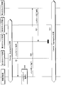
- FIG. 7 is a sequence chart illustrating a procedure from the completion of the handover to the completion of the handover performed by the mobile station device in the carrier aggregation receiving the handover instruction message in the present embodiment.
- FIG. 7 is a continuation of FIG. 6, and in the state where the mobile station apparatus receives the first carrier element to the third carrier element by Carrier Aggregation (Carrier Aggregation state: step S1). The procedure until the second carrier element is excluded from the target of Carrier Aggregation and the fourth carrier element is newly received according to the instruction message (step S6) is shown.
- the description of the mobile station apparatus and carrier elements in the figure is the same as in FIG.
- the mobile station apparatus that has received the handover instruction message starts the handover process (step S7).
- information on the carrier element to be handed over (carrier element information) is acquired.
- the carrier element information includes at least frequency band information and a cell ID.
- the mobile station apparatus stops the reception branch receiving the transmission signal of the base station apparatus of the carrier element (source cell) of the handover source, and corresponds to the base station apparatus of the newly designated carrier element (target cell)
- the reception branch is operated, reception of a transmission signal from the base station apparatus of the newly designated carrier element (target cell) is started, and radio synchronization is attempted.
- the reception branch that receives the transmission signal from the target cell does not have to be the reception branch that has received the signal from the source cell.
- the downlink carrier element and the uplink carrier element correspond one-to-one
- the transmission branch that transmits the transmission signal to the base station apparatus of the carrier element (source cell) that is the handover source is also stopped.
- the mobile station apparatus that has completed the radio synchronization subsequently operates the transmission branch corresponding to the base station apparatus of the newly designated carrier element (target cell), and sets the random access channel to the base corresponding to the fourth carrier element. It transmits to a station apparatus (step S8).
- the dedicated preamble sequence is specified in the handover instruction message, the preamble sequence is used.
- the base station apparatus corresponding to the fourth carrier element that has detected the random access channel transmits a random access response to the mobile station apparatus (step S9).
- the mobile station apparatus that has received the random access response transmits a handover completion message to the base station apparatus corresponding to the fourth carrier element (step S10).
- the base station apparatus of the fourth carrier element notifies the base station apparatus of the handover destination carrier element that the handover has been normally completed with a handover completion notification message, and the procedure is completed (step S11). There may be a case where the base station apparatus of the handover destination and the carrier element of the handover source are the same. Then, the carrier station and the first, third, and fourth carrier elements enter the carrier aggregation state (step S12).
- the mobile station apparatus ID necessary for receiving the random access response may be notified by a handover instruction message, or the mobile station apparatus ID (Cell-Radio Network Temporary Identifier, C- It is also possible to use (without changing) RNTI).
- the mobile station apparatus ID used before the handover the same mobile station apparatus ID is used in all carrier aggregation carrier elements, and when notified by the handover instruction message, the notified mobile station apparatus is used. If the ID is used for reception of the corresponding carrier element and is not notified, the same mobile station apparatus ID is continuously used.
- FIG. 7 a sequence of transmitting a handover completion message to a base station apparatus other than a newly received carrier element (target cell) can be taken.
- An example of this is shown in FIG.
- the description of the mobile station apparatus and carrier elements in FIG. 8 is the same as in FIG.
- the mobile station apparatus that has received the handover instruction message (step S6) starts the handover process (step S7).
- information on the carrier element (source cell) to be changed (carrier element information) is acquired.
- the carrier element information includes at least frequency band information and a cell ID.
- the handover instruction message separately includes handover completion message transmission carrier element information for transmitting a handover completion message.
- the mobile station apparatus stops the reception branch receiving the transmission signal of the base station apparatus of the carrier element (source cell) of the handover source, and corresponds to the base station apparatus of the newly designated carrier element (target cell)
- the reception branch is operated, reception of a transmission signal from the base station apparatus of the newly designated carrier element (target cell) is started, and radio synchronization is attempted.
- the reception branch that receives the transmission signal from the target cell does not have to be the reception branch that has received the signal from the source cell.
- the transmission branch that transmits the transmission signal to the base station apparatus of the carrier element (source cell) that is the handover source is also stopped.
- the mobile station apparatus that has completed the radio synchronization subsequently operates the transmission branch corresponding to the base station apparatus of the newly designated carrier element (target cell), and sets the random access channel to the base corresponding to the fourth carrier element. It transmits to a station apparatus (step S8).
- the dedicated preamble sequence is specified in the handover instruction message
- the preamble sequence is used.
- the base station apparatus corresponding to the fourth carrier element that has detected the random access channel transmits a random access response to the mobile station apparatus (step S9).
- the mobile station apparatus that has received the random access response transmits a handover completion message to the base station apparatus corresponding to the handover completion message transmission carrier element information specified by the handover instruction message (step S14).
- FIG. 8 shows that the base station apparatus of the third carrier element has been instructed.
- the base station apparatus of the third carrier element notifies the handover source and handover destination carrier element base station apparatuses of the handover completion with a handover completion notification message and completes the procedure (steps S15 and S16). ).
- the handover completion message can be transmitted by the handover destination carrier element.
- the handover completion message can be transmitted by the carrier element that has received the handover instruction message. Then, the carrier station and the first, third, and fourth carrier elements enter the carrier aggregation state (step S12).
- the base station apparatus may transmit the carrier element information for transmitting the handover complete message in the random access response.
- Carrier element information included in the handover complete message or the random access response is selected by the base station apparatus, and the selection criteria take into account the reported downlink reception quality, the load state of the base station apparatus, and the presence or absence of resource allocation. I can do it. Since it is possible to transmit the handover completion message using the carrier element determined to be optimal by the base station apparatus, the delivery probability of the handover completion message is improved.
- an existing control message may be reused by EUTRA.
- the handover instruction message can be reused simply by adding the necessary parameters to the RRC Connection Reconfiguration message, and the handover completion message by adding the necessary parameters to the RRC Connection Reconfiguration Complete message.
- a maximum of one carrier element is exchanged by handover. This is because, in order to simultaneously replace a plurality of carrier elements, wireless synchronization and random access procedures are required for each carrier element, and the processing becomes complicated.
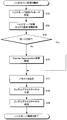
- FIG. 9 is a flowchart showing an example of handover carrier element determination in FIG.
- This processing procedure is preferably performed by the base station apparatus, but the control station may include the processing procedure.
- a measurement report message including a measurement result corresponding to at least one carrier element in the carrier aggregation state is received (step S17).
- the measurement results (downlink reception quality, established handover conditions, etc.) of each carrier element reported in the measurement report message are acquired, and it is determined whether handover is necessary based on the acquired measurement results (step S18). .
- step S19 one carrier element (target cell) appropriate for handover is selected in the handover target carrier element selection. Then, a handover request message for notifying the selected carrier element of handover is generated (step S20), and the handover request message is transmitted (step S21).
- the flowchart in FIG. 9 is an example of a processing procedure in the base station apparatus or the control station, for example, and the necessity of handover of the mobile station apparatus based on the measurement result of the carrier element received by the mobile station apparatus in the Carrier Aggregation state As long as the method selects the carrier element to be changed by the handover, a processing procedure other than this may be used.
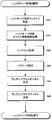
- FIG. 10 is a flowchart showing an example of a handover process procedure of the mobile station apparatus in FIGS.
- the mobile station apparatus receives the handover instruction message transmitted from the base station apparatus (step S22). Then, the handover control content is confirmed in the handover target carrier element information acquisition (step S23). Specifically, it grasps any carrier element (source cell) that is currently undergoing carrier aggregation, which is the handover source, and the carrier element (target cell) that is the handover destination. As described above, information on the source cell is not notified, and the mobile station apparatus determines that the carrier element that has received the handover instruction message is the source cell.
- step S24 switching from the source cell to the target cell is performed (step S24). Specifically, in order to receive the downlink transmission signal from the base station apparatus corresponding to the carrier element of the handover destination, it is necessary for the reception apparatus of the mobile station apparatus to receive the reception frequency band, bandwidth and other physical channels. Set parameters and try to establish synchronization. If the synchronization establishment is successful, a random access channel is generated (step S25). When the dedicated preamble sequence is specified, a random access channel is generated based on the dedicated preamble sequence. When the dedicated preamble sequence is not designated, a random access channel is generated based on the randomly selected preamble sequence. Then, the generated random access channel is transmitted to the base station apparatus of the carrier element that is the handover destination (step S26).
- the flowchart in FIG. 10 is an example of a processing procedure in the mobile station apparatus.
- the mobile station apparatus grasps the handover source carrier element and the handover destination carrier element from the received handover instruction message, and based on the designated parameters. Any other processing procedure may be used as long as the method executes a handover.
- the mobile station apparatus performs a measurement report on handover by distinguishing between a carrier element (cell) having the same carrier element ID and a different carrier element (cell) in the Carrear Aggregation state. Also, the mobile station apparatus starts a handover procedure for a carrier element (cell) having the same carrier element ID according to an instruction from the base station apparatus, and changes the carrier element (cell). The base station apparatus notifies the mobile station apparatus of the carrier element (cell) to be handed over based on the measurement report of the mobile station apparatus.
- the mobile station apparatus can distinguish and control measurement reports related to Carrier Aggregation and other measurement reports, and there is no need to transmit unnecessary measurement results to the base station apparatus.
- the base station apparatus does not need to include information on a carrier element that stops reception after the handover in the handover instruction message. Therefore, the amount of signaling information can be reduced.
- the delivery probability of the handover completion message is improved, and the handover success probability can be improved.
- the handover instruction message is transmitted from the carrier element (cell) of the handover source.
- the fact that handover is instructed means a carrier element (cell) having relatively poor reception quality, and there is a high probability that reception of a handover instruction message will fail. Therefore, in this embodiment, a method of improving the reception success probability of the handover instruction message and the handover success probability by transmitting the handover instruction message on another carrier element that is carrier aggregated will be described.
- the receiver and transmitter of the mobile station apparatus and the receiver and transmitter of the base station apparatus in this embodiment may be the same as those in the first embodiment.
- the network configuration of this embodiment may be the same as in FIG.
- FIG. 11 is a sequence chart showing a procedure until the base station apparatus determines the necessity of handover of the mobile station apparatus during Carrier Aggregation and notifies the handover instruction in the present embodiment. Since the base station apparatus of the second carrier element (source cell) that has received the measurement report message is the same as FIG. 6 until it receives the handover request permission message, the description thereof is omitted. That is, the measurement report message includes at least information (cell ID, frequency band, CCID, etc.) that identifies the established handover condition and the established carrier element (target cell).
- the base station apparatus of the carrier element that has received the handover request permission message makes a message transmission carrier element determination (step S27), and is the most suitable carrier for transmitting a handover instruction message to the mobile station apparatus.
- An element (cell) is selected, and a handover instruction message is transferred to the base station apparatus of the selected carrier element (step S28).
- the handover source carrier element is not selected.
- the carrier element that has received the handover request permission message is optimal, the message is not transferred.
- the carrier element base station apparatus to which the handover instruction message has been transferred transmits the handover instruction message to the mobile station apparatus (step S29).
- FIG. 11 shows an example in which the first carrier element is determined to be optimal as the carrier element (cell) for transmitting the handover instruction message, and the handover instruction message is transferred from the second carrier element.
- the base station apparatus includes source cell identification information for designating which of the carrier elements currently being carrier aggregated is a handover target.
- the source cell identification information is, for example, a cell ID, a frequency band, or a CCID.
- the handover request message and the handover request permission message can be exchanged via the control station.
- the control station includes message transmission carrier element determination.
- the control station includes message transmission carrier element determination.
- the carrier element for transmitting the handover instruction message is determined by the control station, and the handover request permission message is determined by the base station determined by the control station. Sent to the device (not shown).
- FIG. 12 is a sequence chart illustrating a procedure from the completion of the handover to the completion of the handover by the mobile station device in the carrier aggregation that has received the handover instruction message in the present embodiment.
- FIG. 12 shows a continuation of FIG. 11 and is the same as FIG. 7 except that the handover instruction message may be transmitted from other than the base station apparatus of the handover source carrier element (source cell). It is.
- the description of the mobile station apparatus and carrier elements in the figure is the same as in FIG.
- the mobile station apparatus that has received the handover instruction message (step S29) starts the handover process 2 (step S30).
- information on the carrier element to be handed over (carrier element information) and source cell identification information are acquired.
- the carrier element information includes at least frequency band information and a cell ID.
- the mobile station apparatus stops the reception branch receiving the transmission signal of the base station apparatus of the carrier element (source cell) of the handover source, and corresponds to the base station apparatus of the newly designated carrier element (target cell)
- the reception branch is operated, reception of a transmission signal from the base station apparatus of the newly designated carrier element (target cell) is started, and radio synchronization is attempted.
- the reception branch that receives the transmission signal from the target cell does not have to be the reception branch that has received the signal from the source cell.
- the downlink carrier element and the uplink carrier element correspond one-to-one
- the transmission branch that transmits the transmission signal to the base station apparatus of the carrier element (source cell) that is the handover source is also stopped.
- the mobile station apparatus that has completed the radio synchronization subsequently operates the transmission branch corresponding to the base station apparatus of the newly designated carrier element (target cell), and sets the random access channel to the base corresponding to the fourth carrier element. It transmits to a station apparatus (step S31).
- the dedicated preamble sequence is specified in the handover instruction message, the preamble sequence is used.
- the base station apparatus corresponding to the fourth carrier element that has detected the random access channel transmits a random access response to the mobile station apparatus (step S32).
- the mobile station apparatus that has received the random access response transmits a handover completion message to the base station apparatus corresponding to the fourth carrier element (step S33).
- the base station apparatus of the fourth carrier element notifies the base station apparatus of the handover destination carrier element that the handover has been normally completed with a handover completion notification message, and the procedure is completed (step S34). There may be a case where the base station apparatus of the handover destination and the carrier element of the handover source are the same.
- a sequence of transmitting a handover completion message to a base station apparatus other than a newly received carrier element (target cell) can be taken.
- An example of this is shown in FIG.
- the description of the mobile station apparatus and carrier elements in the figure is the same as in FIG.
- the mobile station apparatus that has received the handover instruction message (step S29) starts the handover process 2 (step S30).
- information (carrier element information) of the carrier element (source cell) to be changed is acquired.
- the carrier element information includes at least frequency band information and a cell ID.
- the handover instruction message separately includes handover completion message transmission carrier element information for transmitting a handover completion message.
- the mobile station apparatus stops the reception branch receiving the transmission signal of the base station apparatus of the carrier element (source cell) of the handover source, and corresponds to the base station apparatus of the newly designated carrier element (target cell)
- the reception branch is operated, reception of a transmission signal from the base station apparatus of the newly designated carrier element (target cell) is started, and radio synchronization is attempted.
- the reception branch that receives the transmission signal from the target cell does not have to be the reception branch that has received the signal from the source cell.
- the transmission branch that transmits the transmission signal to the base station apparatus of the carrier element (source cell) that is the handover source is also stopped.
- the mobile station apparatus that has completed the radio synchronization subsequently operates the transmission branch corresponding to the base station apparatus of the newly designated carrier element (target cell), and sets the random access channel to the base corresponding to the fourth carrier element. It transmits to a station apparatus (step S31).
- the dedicated preamble sequence is specified in the handover instruction message
- the preamble sequence is used.
- the base station apparatus corresponding to the fourth carrier element that has detected the random access channel transmits a random access response to the mobile station apparatus (step S32).
- the mobile station apparatus that has received the random access response transmits a handover completion message to the base station apparatus corresponding to the handover completion message transmission carrier element information specified by the handover instruction message (step S35).
- FIG. 13 shows that the base station apparatus of the first carrier element has been instructed.
- the base station apparatus of the first carrier element notifies the base station apparatus of the handover source and handover destination carrier elements that the handover has been normally completed with a handover completion notification message, and completes the procedure (steps S36 and S37). ).
- the handover completion message can be transmitted by the handover destination carrier element.
- the handover completion message can be transmitted by the carrier element that has received the handover instruction message.
- the base station apparatus may transmit the carrier element information for transmitting the handover complete message in the random access response.
- Carrier element information included in the handover complete message or the random access response is selected by the base station apparatus, and the selection criteria take into account the reported downlink reception quality, the load state of the base station apparatus, and the presence or absence of resource allocation. I can do it. Since it is possible to transmit the handover completion message using the carrier element determined to be optimal by the base station apparatus, the delivery probability of the handover completion message is improved.
- the control messages in FIGS. 11 to 14 may be reused by existing control messages in EUTRA.
- the handover instruction message can be reused simply by adding the necessary parameters to the RRC Connection Reconfiguration message, and the handover completion message by adding the necessary parameters to the RRC Connection Reconfiguration Complete message.
- the maximum number of carrier elements that can be replaced by handover is one. This is because, in order to simultaneously replace a plurality of carrier elements, wireless synchronization and random access procedures are required for each carrier element, and the processing becomes complicated.
- FIG. 14 is a flowchart showing an example of message transmission carrier element determination in FIG. This processing procedure is preferably performed in the base station apparatus of the carrier element that has received the handover request permission message, but the control station may include this processing procedure.
- the handover destination carrier element base station apparatus is notified of the completion of handover preparation (step S38).
- the carrier elements in the carrier aggregation are compared (step S39), and one base station apparatus of the carrier element that transmits the handover instruction message is selected (step S40).
- selection criteria the reported downlink reception quality, the load state of the base station apparatus, and the presence or absence of resource allocation can be considered.
- step S41 it is determined whether or not the handover instruction message needs to be transferred to the selected message transmission carrier element. That is, when a carrier element that is executing this processing procedure is selected, there is no need for transfer, and the processing ends.
- the selected carrier element is designated as the transfer destination and the handover instruction message is transferred (step S42).
- the flowchart in FIG. 14 is an example of a processing procedure in the base station apparatus or the control station, for example, and is the optimum carrier for transmitting the handover instruction message among the carrier elements received by the mobile station apparatus in the carrier aggregation state. Any other procedure may be used as long as it is a method for selecting an element.
- FIG. 15 is a flowchart showing an example of a handover process procedure of the mobile station apparatus in FIGS.
- the mobile station apparatus receives the handover instruction message transmitted from the base station apparatus (step S43).
- the handover control content is confirmed in the handover target carrier element information acquisition (step S44). Specifically, it grasps any carrier element (source cell) that is currently undergoing carrier aggregation, which is the handover source, and the carrier element (target cell) that is the handover destination.
- the source cell grasped from the source cell identification information notified by the handover instruction message (step S45).
- step S46 switching from the source cell to the target cell is performed (step S46). Specifically, in order to receive the downlink transmission signal from the base station apparatus corresponding to the carrier element of the handover destination, it is necessary for the reception apparatus of the mobile station apparatus to receive the reception frequency band, bandwidth and other physical channels. Set parameters and try to establish synchronization. If the synchronization is successfully established, a random access channel is generated (step S47). When the dedicated preamble sequence is specified, a random access channel is generated based on the dedicated preamble sequence. When the dedicated preamble sequence is not designated, a random access channel is generated based on the randomly selected preamble sequence. Then, the generated random access channel is transmitted to the base station apparatus of the carrier element that is the handover destination (step S48).
- the flowchart in FIG. 15 is an example of a processing procedure in the mobile station apparatus.
- the mobile station apparatus grasps the handover source carrier element and the handover destination carrier element from the received handover instruction message, and based on the designated parameters. Any other processing procedure may be used as long as the method executes a handover.
- the base station apparatus selects the base station apparatus with the optimum carrier element at the time of handover execution as the base station apparatus with the carrier element that transmits the handover instruction message. Further, the mobile station apparatus identifies the handover source carrier element based on the source cell identification information included in the handover instruction message.
- the base station apparatus when the mobile station apparatus receives a plurality of frequency bands in the Carrier Aggregation state, the base station apparatus can transmit a handover instruction message in the optimum frequency band.
- the message delivery probability is improved, and the handover success probability can be improved.
- a method is shown in which a random access procedure can be omitted and a handover can be performed at high speed.
- the receiver and transmitter of the mobile station apparatus and the receiver and transmitter of the base station apparatus in this embodiment may be the same as those in the first embodiment.
- the carrier element in the carrier aggregation and the carrier element of the handover destination must all be controlled by the same base station apparatus.
- FIG. 16 is a sequence chart illustrating a procedure until the mobile station device that is undergoing Carrier Aggregation that has received the handover instruction message executes handover and completes in this embodiment.
- the description of the mobile station apparatus and carrier elements in the figure is the same as in FIGS.
- the mobile station apparatus that has received the handover instruction message (step S2) starts the handover process 3 (step S49).
- information on the carrier element to be handed over (carrier element information) and source cell identification information are acquired.
- the carrier element information includes at least frequency band information and a cell ID.
- the mobile station apparatus stops the reception branch receiving the transmission signal of the base station apparatus of the carrier element (source cell) of the handover source, and corresponds to the base station apparatus of the newly designated carrier element (target cell)
- the reception branch is operated, reception of a transmission signal from the base station apparatus of the newly designated carrier element (target cell) is started, and radio synchronization is attempted.
- the reception branch that receives the transmission signal from the target cell does not have to be the reception branch that has received the signal from the source cell.
- the downlink carrier element and the uplink carrier element correspond one-to-one
- the transmission branch that transmits the transmission signal to the base station apparatus of the carrier element (source cell) that is the handover source is also stopped.
- the mobile station apparatus that has completed radio synchronization omits transmission of the random access channel, operates the transmission branch corresponding to the base station apparatus of the newly designated carrier element (target cell), and sends a handover complete message at the handover destination. It transmits to the base station apparatus corresponding to a certain carrier element (step S50).
- the resource allocation information for transmitting the handover completion message is obtained by receiving the downlink shared control channel included in the handover instruction message or transmitted by the base station apparatus of the handover destination carrier element. This example shows a case where a fourth carrier element is designated as the handover destination carrier element.
- the base station apparatus of the fourth carrier element notifies the base station apparatus of the handover destination carrier element that the handover has been normally completed with a handover completion notification message, and the procedure is completed (step S51).
- the handover completion notification message may be omitted.
- FIG. 17 is a flowchart showing an example of a handover process procedure of the mobile station apparatus in FIG.
- the mobile station apparatus receives the handover instruction message transmitted from the base station apparatus (step S52). Then, in the handover target carrier element information acquisition, the handover control content is confirmed (step S53). Specifically, it grasps any carrier element (source cell) that is currently undergoing carrier aggregation, which is the handover source, and the carrier element (target cell) that is the handover destination.
- the carrier element that has received the handover instruction message is determined as the source cell as in the first embodiment, it is clearly indicated by the source cell identification information included in the handover instruction message as in the second embodiment.
- a source cell may be designated.
- switching from the source cell to the target cell is performed (step S54). Specifically, in order to receive the downlink transmission signal from the base station apparatus corresponding to the carrier element of the handover destination, it is necessary for the reception apparatus of the mobile station apparatus to receive the reception frequency band, bandwidth and other physical channels. Set parameters and try to establish synchronization. Further, the mobile station apparatus determines whether or not the handover requires a random access procedure based on the information notified by the handover instruction message (step S55).
- the base station apparatus can cause the mobile station apparatus to determine that the random access procedure is unnecessary using any of the following methods.
- (1) Include a random access unnecessary identifier in the handover instruction message, (2) Reserve a part of the number of the dedicated preamble, and specify the number of the dedicated preamble in the handover instruction message, (3) Same CCID in the handover instruction message
- a carrier element having the same cell ID in a different frequency band is designated as a target cell.
- a handover instruction message with the same mobile station apparatus ID as the currently used mobile station apparatus ID (C-RNTI) (5)
- the uplink carrier element corresponding to the target cell for which synchronization has been successfully established is equal to any of the currently transmitted uplink carrier elements (in FIG.
- the frequency band of the corresponding uplink carrier element can be known from the broadcast information of the target cell, or can be included in the handover instruction message.
- the mobile station device If it is determined that the random access procedure is necessary, the mobile station device generates a random access channel after synchronization is established (step S56).
- a random access channel is generated based on the dedicated preamble sequence.
- a random access channel is generated based on the randomly selected preamble sequence. Then, the generated random access channel is transmitted to the base station apparatus of the carrier element that is the handover destination (step S57).
- the mobile station apparatus determines that the random access procedure is unnecessary, it generates a handover complete message after establishing synchronization (step S58). Then, the generated handover completion message is transmitted to the base station apparatus of the carrier element that is the handover destination (step S59).
- the flowchart in FIG. 17 is an example of a processing procedure in the mobile station apparatus, and the mobile station apparatus grasps the handover source carrier element and the handover destination carrier element from the received handover instruction message, and further determines the random access channel. If it is a method for determining whether transmission is necessary and executing either a handover procedure that requires a random access procedure or a handover that does not require a random access procedure based on the specified parameters, other processing A procedure may be used.
- the base station apparatus notifies the mobile station apparatus of either a handover that requires a random access procedure or a handover that requires a random access procedure. Also, the mobile station apparatus determines a handover that requires a random access procedure and a handover that requires a random access procedure based on an instruction from the base station apparatus, and executes a handover procedure based on the determination.
- the base station apparatus when there is no need to transmit a random access channel to establish uplink synchronization, the base station apparatus can omit the random access procedure and reduce the processing time required for the handover procedure. Because communication interruptions can be reduced, communication quality is improved. Further, the mobile station apparatus can reduce the power consumption required at the time of handover by omitting the random access procedure.
- a fourth embodiment of the present invention will be described.
- a handover procedure such as soft handover, in which at least one of the frequency bands received by the mobile station apparatus does not change before and after the handover procedure has been described.
- it is very complicated to compare the reception quality of each carrier element in the carrier aggregation state with the reception quality of the carrier elements in each frequency band of the neighboring base station apparatus, and the calculation processing of the mobile station apparatus is enormous. There is a fear.
- the present embodiment a method for simplifying the handover procedure by limiting the carrier elements to be measured in order to determine the necessity of the handover and releasing the Carrier Aggregation state at the time of handover will be described.
- the receiver and transmitter of the mobile station apparatus and the receiver and transmitter of the base station apparatus in this embodiment may be the same as those in the first embodiment.
- the network configuration of this embodiment may be the same as in FIG.
- FIG. 18 is an example of a sequence illustrating a procedure from when the mobile station apparatus that is receiving the handover instruction message to the Carrier Aggregation in the present embodiment executes the handover and completes the handover.
- the description of the mobile station apparatus and carrier elements in the figure is the same as in FIGS.
- the mobile station apparatus of this embodiment is in the Carrier Aggregation state of the measurement report for handover in order to reduce the amount of computation required for comparison of uplink resources necessary for the measurement report message and reception quality between carrier elements. This is not performed for all carrier elements, but limited to only one representative carrier element (hereinafter referred to as a main carrier).
- the mobile station apparatus determines the main carrier by one of the following methods. (1) Designated individually for each mobile station device by a control message from the base station device, (2) The largest or smallest value among the values specific to the carrier element (cell), (3) Carrear Aggregation
- the measurement frequency dedicated to the main carrier is indicated by the control message from the base station apparatus, which is the lowest frequency band or the highest frequency band among the existing carrier elements.
- the broadcast information may include a specific numerical value, or a cell ID or a global cell ID may be used. Due to this limitation, for example, when five carrier elements (cells) of the first carrier element to the fifth carrier element are Carrier Aggregated, conventionally, comparison of reception quality between carriers in the Carrier Aggregation state is There are 10 combinations, but if only the main carrier and other carrier elements are limited, the number of combinations can be reduced to 4.
- the mobile station apparatus that has received the handover instruction message (step S2) starts the handover process 4 (step S60).
- the handover process 4 information on the carrier element (carrier element information) to be handed over is acquired.
- Carrier element information includes at least frequency band information and a cell ID, and indicates a target cell. Since the base station apparatus does not need information on the carrier element (source cell) of the handover source, it is not included in the handover instruction message.
- the mobile station apparatus stops the reception branch receiving the transmission signal of the base station apparatus of all the carrier elements in the carrier aggregation state, and corresponds to the base station apparatus of the newly designated carrier element (target cell)
- the reception branch is operated, reception of a transmission signal from the base station apparatus of the newly designated carrier element (target cell) is started, and radio synchronization is attempted.
- the reception branch that receives the transmission signal from the target cell does not have to be the reception branch that has received the signal from the source cell.
- the transmission branch that transmits the transmission signal to the base station apparatus of the carrier element (source cell) that is the handover source is also stopped.
- the mobile station apparatus that has completed the radio synchronization subsequently operates the transmission branch corresponding to the base station apparatus of the newly designated carrier element (target cell), and sets the random access channel to the base corresponding to the fourth carrier element. It transmits to a station apparatus (step S61).
- the dedicated preamble sequence is specified in the handover instruction message
- the preamble sequence is used.
- the base station apparatus corresponding to the fourth carrier element that has detected the random access channel transmits a random access response to the mobile station apparatus (step S62).
- the mobile station apparatus that has received the random access response transmits a handover completion message to the base station apparatus corresponding to the fourth carrier element (step S63).
- the base station apparatus of the fourth carrier element notifies the carrier element base station apparatus that carried out carrier aggregation prior to the handover with a handover completion notification message to complete the procedure (step S64, Step S65, Step S66).
- FIG. 18 shows an example in which a handover completion notification message is transmitted to each carrier element. However, if all the carrier elements that were subjected to Carrier Aggregation before the handover are different frequency bands of the same base station apparatus, the handover is performed.
- the completion notification message may be sent once. There may be a case where the base station apparatus of the handover destination and the carrier element of the handover source are the same.
- FIG. 19 is a flowchart showing an example of a handover process procedure of the mobile station apparatus in FIG.
- the mobile station apparatus receives the handover instruction message transmitted from the base station apparatus (step S67). Then, the handover control content is confirmed in the handover target carrier element information acquisition (step S68). Specifically, the carrier element (target cell) of the handover destination is grasped.
- the mobile station apparatus determines that all carrier elements in the current Carrier Aggregation state are targeted for the handover source carrier element. Subsequently, in the carrier aggregation cancellation, reception of all transmission signals from the carrier element (cell) currently carrying out carrier aggregation is stopped (step S69).
- step S69 switching from the source cell to the target cell is performed. Specifically, in order to receive the downlink transmission signal from the base station apparatus corresponding to the carrier element of the handover destination, it is necessary for the reception apparatus of the mobile station apparatus to receive the reception frequency band, bandwidth and other physical channels. Parameters are set and synchronization establishment is attempted (step S70).
- a random access channel is generated (step S71).
- a random access channel is generated based on the dedicated preamble sequence.
- a random access channel is generated based on the randomly selected preamble sequence. Then, the generated random access channel is transmitted to the base station apparatus of the carrier element that is the handover destination (step S72).
- the flowchart of FIG. 19 is an example of a processing procedure in the mobile station apparatus, and the mobile station apparatus determines that it is necessary to release all the carrier elements that are currently in the Carrier Aggregation state after receiving the handover instruction message. Any other procedure may be used as long as it is a method for executing a handover.
- FIG. 20 shows a modification of the handover process 4 of FIG. A difference from FIG. 19 is that an identical CCID determination process is added.
- the mobile station apparatus receives the handover instruction message transmitted from the base station apparatus (step S73).
- the handover target carrier element information acquisition the handover control content is confirmed (step S74).
- the carrier element (target cell) of the handover destination and the CCID are grasped.
- step S75 the reception of all transmission signals from the carrier elements (cells) currently carrying out carrier aggregation is stopped in the carrier aggregation cancellation (step S76).
- step S76 The subsequent processing (steps S77 to S79) is the same as steps S70 to S72 in FIG. If the CCIDs are the same, it is determined that the handover is in the Carrier Aggregation state and the Carrier Aggregation state is maintained with any carrier element as the source cell. Then, the carrier element (source cell) of the handover source is grasped by using the method of the first embodiment or the second embodiment.
- the subsequent processing (steps S77 to S79) is the same as steps S70 to S72 in FIG.
- a method of omitting the random access procedure as in the third embodiment can be used (not shown).
- the mobile station apparatus can greatly reduce the amount of calculation for comparing the reception quality of each carrier element. Further, even when the mobile station apparatus receives a plurality of frequency bands in the Carrier Aggregation state, the base station apparatus does not need to include information on a carrier element that stops reception after the handover in the handover instruction message. Therefore, the amount of signaling information can be reduced. In addition, since it is not necessary to include information on a carrier element that transmits a handover completion message, the amount of signaling information can be reduced.
- the function of each unit of the mobile station apparatus and the base station apparatus or a program for realizing a part of these functions is recorded on a computer-readable recording medium and recorded on this recording medium.
- the mobile station apparatus or the base station apparatus may be controlled by causing the computer system to read and execute the program.
- the “computer system” includes an OS and hardware such as peripheral devices.
- the “computer-readable recording medium” refers to a storage device such as a flexible medium, a magneto-optical disk, a portable medium such as a ROM or a CD-ROM, and a hard disk incorporated in a computer system.
- the “computer-readable recording medium” dynamically holds a program for a short time, like a communication line when transmitting a program via a network such as the Internet or a communication line such as a telephone line.
- a server that holds a program for a certain time such as a volatile memory inside a computer system that serves as a server or client.
- the program may be a program for realizing a part of the functions described above, and may be a program capable of realizing the functions described above in combination with a program already recorded in a computer system.
Abstract
Description
図21は、従来のW-CDMA方式におけるハードハンドオーバ手順を示すシーケンスチャートである。図21では、移動局装置と、周波数帯域1を使用する第1の基地局装置~第3の基地局装置と、周波数帯域2を使用する第4の基地局装置を示している。なお、第1の基地局装置~第3の基地局装置は別の基地局装置でも良いし、同じ基地局装置の異なる送信装置であってもよい。 (1) Handover procedure (soft handover, hard handover)
FIG. 21 is a sequence chart showing a hard handover procedure in the conventional W-CDMA system. FIG. 21 shows a mobile station apparatus, first to third base station apparatuses that use
図24は、Carrier Aggregationを用いた受信周波数帯域の増減の様子を示す図である。Band1~Band3は、それぞれ基地局装置が送信する下りの周波数帯域を示しており、その送信帯域幅は例えば20MHzである。なお、Band1~Band3は連続した周波数帯域であっても、全てまたは一部が不連続となる周波数帯域であってもよい。ただし、移動局装置は20MHz以上の受信帯域幅を持つ必要あり、本例では20MHzの周波数帯域を同時に3つまで受信可能であり、その受信帯域幅の合計は60MHzである。 (2) Carrier Aggregation
FIG. 24 is a diagram illustrating how the reception frequency band is increased / decreased using Carrier Aggregation.
EUTRAおよびAdvanced EUTRAで使用される物理チャネルは、物理報知情報チャネル、上りデータチャネル、下りデータチャネル、下り共用制御チャネル、上り共用制御チャネル、ランダムアクセスチャネル、同期シグナル、下りリファレンスシグナル、上りリファレンスシグナルなどがある。 (3) Physical channel The physical channel used in EUTRA and Advanced EUTRA is a physical broadcast information channel, an uplink data channel, a downlink data channel, a downlink shared control channel, an uplink shared control channel, a random access channel, a synchronization signal, and a downlink reference signal. There is an uplink reference signal.
次に、本発明の第1の実施形態について説明する。図1Aは、本発明の第1の実施形態に係る移動局装置の構成の一例を示すブロック図である。また、図1Bは、本実施形態で想定しているCarrier Aggregationを示す図である。移動局装置構成は、対応する周波数帯域(例えば800MHzバンド、2.4GHzバンド、3.4GHzバンド)により、複数の送受信部により構成されている。図1Aは図1Bに示したCarrier Aggregationに対応可能な移動局装置構成を示す。 (First embodiment)
Next, a first embodiment of the present invention will be described. FIG. 1A is a block diagram showing an example of a configuration of a mobile station apparatus according to the first embodiment of the present invention. FIG. 1B is a diagram illustrating Carrier Aggregation assumed in the present embodiment. The mobile station apparatus configuration is configured by a plurality of transmission / reception units in a corresponding frequency band (for example, 800 MHz band, 2.4 GHz band, 3.4 GHz band). FIG. 1A shows a mobile station apparatus configuration that can support the Carrier Aggregation shown in FIG. 1B.
次に、本発明の第2の実施形態について説明する。第1の実施形態では、ハンドオーバ指示メッセージは、ハンドオーバ元のキャリア要素(セル)から送信されていた。しかしながら、ハンドオーバが指示されるということは、比較的受信品質が悪いキャリア要素(セル)であることを意味し、ハンドオーバ指示メッセージの受信を失敗する確率も高い。そこで、本実施形態では、Carrier Aggregationされている他のキャリア要素でハンドオーバ指示メッセージを送信することによって、ハンドオーバ指示メッセージの受信成功確率ならびにハンドオーバ成功確率を向上させる方法を示す。本実施形態における移動局装置の受信装置と送信装置、および基地局装置の受信装置と送信装置は第1の実施形態と同じでよい。本実施形態のネットワーク構成は図5と同じでよい。 (Second Embodiment)
Next, a second embodiment of the present invention will be described. In the first embodiment, the handover instruction message is transmitted from the carrier element (cell) of the handover source. However, the fact that handover is instructed means a carrier element (cell) having relatively poor reception quality, and there is a high probability that reception of a handover instruction message will fail. Therefore, in this embodiment, a method of improving the reception success probability of the handover instruction message and the handover success probability by transmitting the handover instruction message on another carrier element that is carrier aggregated will be described. The receiver and transmitter of the mobile station apparatus and the receiver and transmitter of the base station apparatus in this embodiment may be the same as those in the first embodiment. The network configuration of this embodiment may be the same as in FIG.
次に、本発明の第3の実施形態について説明する。第1の実施形態ならびに第2の実施形態では、ハンドオーバ完了メッセージ前に、ハンドオーバ先のキャリア要素(ターゲットセル)に対してランダムアクセスチャネルを送信し、上り同期を確立させる必要があった。しかし、Carrier Aggregation中の各キャリア要素が同一基地局装置で制御されており、かつ各キャリア要素の上り受信タイミングがほぼ同じであれば、同一基地局装置のキャリア要素を変更するハンドオーバ時において、上り同期を確立する必要が無く、ランダムアクセス手順を省略することが可能となる。 (Third embodiment)
Next, a third embodiment of the present invention will be described. In the first embodiment and the second embodiment, it is necessary to establish uplink synchronization by transmitting a random access channel to a handover destination carrier element (target cell) before a handover completion message. However, if each carrier element in Carrier Aggregation is controlled by the same base station apparatus and the uplink reception timing of each carrier element is substantially the same, at the time of handover for changing the carrier element of the same base station apparatus, There is no need to establish synchronization, and the random access procedure can be omitted.
次に、本発明の第4の実施形態について説明する。第1の実施形態から第3の実施形態では、ソフトハンドオーバのように、移動局装置が受信している周波数帯域のうち、少なくとも一つはハンドオーバ手順の前後で変わらないハンドオーバ手順について説明してきた。しかしながら、Carrier Aggregation状態にある各キャリア要素の受信品質と、周辺基地局装置の各周波数帯域のキャリア要素の受信品質を全て比較するのは非常に複雑であり、移動局装置の計算処理が膨大となる恐れがある。 (Fourth embodiment)
Next, a fourth embodiment of the present invention will be described. In the first to third embodiments, a handover procedure, such as soft handover, in which at least one of the frequency bands received by the mobile station apparatus does not change before and after the handover procedure has been described. However, it is very complicated to compare the reception quality of each carrier element in the carrier aggregation state with the reception quality of the carrier elements in each frequency band of the neighboring base station apparatus, and the calculation processing of the mobile station apparatus is enormous. There is a fear.
2-1、2-2 DUP
3-1、3-2 無線受信部
4-1~4-4 直交復調器
5-1~5-4 ベースバンド復調部
6 ディマッピング部
7 マッピング部
8 送受信帯域設定部
9 送信信号処理制御部
10 受信信号処理制御部
11 ランダムアクセス生成部
12 制御メッセージ処理部
13-1、13-2 無線送信部
14-1~14-4 直交変調器
15-1~15-4 ベースバンド変調部
16 ハンドオーバ制御部
17 上り制御メッセージ生成部
18 測定処理部
20 アンテナ
21 受信部
22 受信信号処理制御部
23 受信信号処理部
24 上りメッセージ処理部
25 ランダムアクセス処理部
26 基地局間メッセージ処理部
31 Aggregation判定部
32 ハンドオーバ判定部
33 下りメッセージ生成部
34 送信信号処理部
35 送信信号処理制御部
36 チャネルマッピング部
37 送信帯域設定部
38-1~38-n 送信部
39 基地局間メッセージ生成部
40-1~40-n アンテナ 1-1, 1-2 Antenna (Transmission and reception)
2-1, 2-2 DUP
3-1, 3-2 Radio Receiving Units 4-1 to 4-4 Orthogonal Demodulators 5-1 to 5-4 Baseband Demodulating Unit 6
Claims (16)
- 一つまたは複数の基地局装置から送信される相互に異なる複数の周波数帯域の送信信号を受信する移動局装置であって、
前記周波数帯域毎に受信処理を行なう複数の受信ブランチと、
動作中の受信ブランチを、前記基地局装置から受信したハンドオーバ開始を示すハンドオーバ指示メッセージで示されたハンドオーバ先の周波数帯域に対応する受信ブランチに切り替える制御を行なう受信信号処理制御部と、を備え、
前記ハンドオーバ指示メッセージで示されたハンドオーバ元の周波数帯域に対応する受信ブランチを停止すると共に、ハンドオーバ指示メッセージで示されたハンドオーバ先の周波数帯域に対応する受信ブランチを動作させることによって、ハンドオーバを行なうことを特徴とする移動局装置。 A mobile station apparatus that receives transmission signals of a plurality of different frequency bands transmitted from one or a plurality of base station apparatuses,
A plurality of reception branches that perform reception processing for each frequency band;
A reception signal processing control unit that performs control to switch the operating reception branch to the reception branch corresponding to the frequency band of the handover destination indicated by the handover instruction message indicating the start of handover received from the base station device,
Performing handover by stopping the reception branch corresponding to the frequency band of the handover source indicated by the handover instruction message and operating the reception branch corresponding to the frequency band of the handover destination indicated by the handover instruction message A mobile station apparatus characterized by the above. - 前記ハンドオーバ指示メッセージを受信した受信ブランチに対応する周波数帯域を、ハンドオーバ元の周波数帯域であると判断することを特徴とする請求項1記載の移動局装置。 The mobile station apparatus according to claim 1, wherein a frequency band corresponding to a reception branch that has received the handover instruction message is determined to be a frequency band of a handover source.
- 前記ハンドオーバ指示メッセージに基づいて、前記ハンドオーバ指示メッセージを受信した受信ブランチに対応する周波数帯域以外のいずれか一つの周波数帯域を、ハンドオーバ元の周波数帯域であると判断することを特徴とする請求項1記載の移動局装置。 The one of the frequency bands other than the frequency band corresponding to the reception branch that has received the handover instruction message is determined to be a handover source frequency band based on the handover instruction message. The mobile station apparatus as described.
- ハンドオーバが完了したことを示すハンドオーバ完了メッセージを、前記ハンドオーバ指示メッセージで示された周波数帯域で送信することを特徴とする請求項1から請求項3のいずれかに記載の移動局装置。 The mobile station apparatus according to any one of claims 1 to 3, wherein a handover completion message indicating completion of handover is transmitted in a frequency band indicated by the handover instruction message.
- ハンドオーバが完了したことを示すハンドオーバ完了メッセージを、ランダムアクセスチャネルの応答に含まれる制御情報で示された周波数帯域で送信することを特徴とする請求項1から請求項3のいずれかに記載の移動局装置。 The handover according to any one of claims 1 to 3, wherein a handover completion message indicating completion of handover is transmitted in a frequency band indicated by control information included in a response of a random access channel. Station equipment.
- すべての前記受信ブランチが送信信号を受信している周波数帯域を、ハンドオーバ元の周波数帯域であると判断することを特徴とする請求項1記載の移動局装置。 The mobile station apparatus according to claim 1, wherein a frequency band in which all the reception branches receive a transmission signal is determined as a handover source frequency band.
- 前記ハンドオーバ指示メッセージに基づいて、ハンドオーバ時にランダムアクセスチャネルの送信が必要であるかどうかを判断し、
前記判断の結果、ランダムアクセスチャネルの送信が不要である場合はランダムアクセス手順を省略してハンドオーバを行なう一方、ランダムアクセスチャネルの送信が必要である場合はランダムアクセス手順を伴うハンドオーバを行なうことを特徴とする請求項1から請求項4のいずれかに記載の移動局装置。 Based on the handover instruction message, determine whether transmission of a random access channel is required at the time of handover,
As a result of the determination, if transmission of a random access channel is not necessary, the random access procedure is omitted and handover is performed, whereas if transmission of the random access channel is necessary, handover with a random access procedure is performed. The mobile station apparatus according to any one of claims 1 to 4. - 相互に異なる複数の周波数帯域の送信信号を受信する移動局装置と無線通信を行なう基地局装置であって、
ハンドオーバ条件が成立した旨を示す測定報告メッセージを送信した移動局装置に対して、ハンドオーバ先の下り周波数帯域を指定する制御情報、およびハンドオーバが完了したことを通知するハンドオーバ完了メッセージを送信する上り周波数帯域を指定する制御情報を含めてハンドオーバ開始を示すハンドオーバ指示メッセージを前記移動局装置に対して送信することを特徴とする基地局装置。 A base station apparatus that performs radio communication with a mobile station apparatus that receives transmission signals of a plurality of mutually different frequency bands,
Uplink frequency for transmitting control information specifying the handover destination downlink frequency band and a handover completion message for notifying that the handover is completed to the mobile station apparatus that has transmitted the measurement report message indicating that the handover condition is established A base station apparatus, comprising: a handover instruction message indicating start of handover including control information designating a band, to the mobile station apparatus. - ハンドオーバ条件が成立した旨を示す測定報告メッセージを送信した移動局装置に対して、ランダムアクセス手順が必要であるか否かを判断し、前記判断に基づいて、ランダムアクセス手順の要否を指定する制御情報を含めてハンドオーバ開始を示すハンドオーバ指示メッセージを前記移動局装置に対して送信することを特徴とする請求項8記載の基地局装置。 It is determined whether or not a random access procedure is necessary for the mobile station apparatus that has transmitted the measurement report message indicating that the handover condition is established, and the necessity of the random access procedure is designated based on the determination. The base station apparatus according to claim 8, wherein a handover instruction message indicating start of handover including control information is transmitted to the mobile station apparatus.
- ランダムアクセス不要識別子をハンドオーバ指示メッセージに含めることによって、ランダムアクセス手順が不要であることを前記移動局装置に通知することを特徴とする請求項9記載の基地局装置。 The base station apparatus according to claim 9, wherein the mobile station apparatus is notified that a random access procedure is unnecessary by including a random access unnecessary identifier in a handover instruction message.
- 個別プリアンブルの番号の一部を予約し、前記個別プリアンブルの番号をハンドオーバ指示メッセージで指定することによって、ランダムアクセス手順が不要であることを前記移動局装置に通知することを特徴とする請求項9記載の基地局装置。 10. The mobile station apparatus is notified that a random access procedure is unnecessary by reserving a part of a dedicated preamble number and specifying the dedicated preamble number in a handover instruction message. The base station apparatus as described.
- 前記移動局装置が受信している下り周波数帯域に割り振られた周波数識別子と同じ周波数識別子をハンドオーバ指示メッセージに含めることによって、ランダムアクセス手順が不要であることを前記移動局装置に通知することを特徴とする請求項9記載の基地局装置。 Including the same frequency identifier as the frequency identifier allocated to the downlink frequency band received by the mobile station device in the handover instruction message notifies the mobile station device that a random access procedure is unnecessary. The base station apparatus according to claim 9.
- 前記移動局装置が使用している移動局装置IDと同じ移動局装置IDをハンドオーバ指示メッセージに含めることによって、ランダムアクセス手順が不要であることを前記移動局装置に通知することを特徴とする請求項9記載の基地局装置。 The mobile station apparatus is notified that a random access procedure is unnecessary by including the same mobile station apparatus ID as the mobile station apparatus ID used by the mobile station apparatus in a handover instruction message. Item 10. The base station apparatus according to Item 9.
- ハンドオーバ前に前記移動局装置がアクセスしていた上り周波数帯域のいずれかと同じ上り周波数帯域をハンドオーバ指示メッセージで指定することによって、ランダムアクセス手順が不要であることを前記移動局装置に通知することを特徴とする請求項9記載の基地局装置。 Notifying the mobile station apparatus that a random access procedure is unnecessary by designating the same uplink frequency band as any of the uplink frequency bands accessed by the mobile station apparatus before the handover by the handover instruction message. The base station apparatus according to claim 9, wherein:
- 一つまたは複数の基地局装置から送信される相互に異なる複数の周波数帯域の送信信号を受信する移動局装置のハンドオーバ方法であって、
前記周波数帯域毎に受信処理を行なう複数の受信ブランチのうち、動作中の受信ブランチを、前記基地局装置から受信したハンドオーバ開始を示すハンドオーバ指示メッセージで示されたハンドオーバ先の周波数帯域に対応する受信ブランチに切り替える制御を行ない、前記ハンドオーバ指示メッセージに示されたハンドオーバ先の周波数帯域に対応する受信ブランチを停止させると共に、ハンドオーバ指示メッセージで示されたハンドオーバ先の周波数帯域に対応する受信ブランチを動作させることによって、ハンドオーバを行なうことを特徴とするハンドオーバ方法。 A mobile station apparatus handover method for receiving transmission signals of a plurality of different frequency bands transmitted from one or a plurality of base station apparatuses,
Among a plurality of reception branches that perform reception processing for each frequency band, an active reception branch is received corresponding to the frequency band of the handover destination indicated by the handover instruction message indicating the start of handover received from the base station apparatus. Control to switch to a branch, stop the reception branch corresponding to the frequency band of the handover destination indicated in the handover instruction message, and operate the reception branch corresponding to the frequency band of the handover destination indicated in the handover instruction message Thus, a handover method characterized by performing a handover. - 請求項1記載の移動局装置と、請求項8記載の基地局装置と、から構成されることを特徴とする移動通信システム。 A mobile communication system comprising the mobile station apparatus according to claim 1 and the base station apparatus according to claim 8.
Priority Applications (4)
| Application Number | Priority Date | Filing Date | Title |
|---|---|---|---|
| CN2010800043929A CN102282890A (en) | 2009-01-16 | 2010-01-06 | Mobile station apparatus, base station apparatus, handoff method, and mobile communication system |
| US13/144,870 US20110292911A1 (en) | 2009-01-16 | 2010-01-06 | Mobile station apparatus, base station apparatus, handover method and mobile communication system |
| JP2010546608A JPWO2010082521A1 (en) | 2009-01-16 | 2010-01-06 | Mobile station apparatus, base station apparatus, handover method, and mobile communication system |
| EP10731190A EP2384052A1 (en) | 2009-01-16 | 2010-01-06 | Mobile station apparatus, base station apparatus, handoff method, and mobile communication system |
Applications Claiming Priority (2)
| Application Number | Priority Date | Filing Date | Title |
|---|---|---|---|
| JP2009-007902 | 2009-01-16 | ||
| JP2009007902 | 2009-01-16 |
Publications (1)
| Publication Number | Publication Date |
|---|---|
| WO2010082521A1 true WO2010082521A1 (en) | 2010-07-22 |
Family
ID=42339774
Family Applications (1)
| Application Number | Title | Priority Date | Filing Date |
|---|---|---|---|
| PCT/JP2010/050074 WO2010082521A1 (en) | 2009-01-16 | 2010-01-06 | Mobile station apparatus, base station apparatus, handoff method, and mobile communication system |
Country Status (5)
| Country | Link |
|---|---|
| US (1) | US20110292911A1 (en) |
| EP (1) | EP2384052A1 (en) |
| JP (1) | JPWO2010082521A1 (en) |
| CN (1) | CN102282890A (en) |
| WO (1) | WO2010082521A1 (en) |
Cited By (15)
| Publication number | Priority date | Publication date | Assignee | Title |
|---|---|---|---|---|
| JP2010220214A (en) * | 2009-03-17 | 2010-09-30 | Kotatsu Kokusai Denshi Kofun Yugenkoshi | Method of establishing multiple link with multiple component carrier and related communication device |
| JP2011254466A (en) * | 2010-05-31 | 2011-12-15 | Ntt Docomo Inc | Handover method, mobile terminal, and base station |
| CN102378296A (en) * | 2010-08-12 | 2012-03-14 | 普天信息技术研究院有限公司 | Method for carrying out frequency band switching in communication system |
| WO2012108046A1 (en) * | 2011-02-10 | 2012-08-16 | 富士通株式会社 | Wireless communication system, receiving device, transmitting device and method of wireless communication |
| WO2012166034A1 (en) * | 2011-06-03 | 2012-12-06 | Telefonaktiebolaget L M Ericsson (Publ) | Carrier aggregation support for home base stations |
| JP2013110673A (en) * | 2011-11-24 | 2013-06-06 | Sumitomo Electric Ind Ltd | Signal measurement method, terminal device and base station device |
| JP2013165454A (en) * | 2012-02-13 | 2013-08-22 | Sharp Corp | Wireless communication system, communication method, base station method, and mobile terminal |
| JP2013534789A (en) * | 2010-07-27 | 2013-09-05 | ソニー株式会社 | Method, device and system for switching cells in a communication system supporting carrier aggregation |
| KR20140131573A (en) * | 2012-03-02 | 2014-11-13 | 퀄컴 인코포레이티드 | Single-chip signal splitting carrier aggregation receiver architecture |
| US8989105B2 (en) | 2009-03-17 | 2015-03-24 | Htc Corporation | Method of establishing multiple links with multiple component carriers and related communication device |
| JP2015526991A (en) * | 2012-07-24 | 2015-09-10 | エンパイア テクノロジー ディベロップメント エルエルシー | Cell switching strategy for LTE-Advanced system based on carrier aggregation technology |
| JP2017512028A (en) * | 2014-03-06 | 2017-04-27 | 華為技術有限公司Huawei Technologies Co.,Ltd. | Base station, terminal, and handover method |
| JP2017526281A (en) * | 2014-09-24 | 2017-09-07 | インテル コーポレイション | Handover when releasing spectrum for licensed shared access |
| JP2017163415A (en) * | 2016-03-10 | 2017-09-14 | Kddi株式会社 | Base station device, terminal device, control method, and program |
| WO2022030453A1 (en) * | 2020-08-03 | 2022-02-10 | 京セラ株式会社 | Communication control method |
Families Citing this family (23)
| Publication number | Priority date | Publication date | Assignee | Title |
|---|---|---|---|---|
| CN101925155A (en) * | 2009-06-11 | 2010-12-22 | 中兴通讯股份有限公司 | Carrier distributing method and device of carrier aggregation system |
| KR101710607B1 (en) * | 2010-01-20 | 2017-02-27 | 삼성전자주식회사 | Method and apparatus for surpporting handover of user equipment in mobile system |
| JP5440248B2 (en) | 2010-02-25 | 2014-03-12 | ソニー株式会社 | Method for controlling handover, terminal device, base station, and radio communication system |
| EP3206327B1 (en) * | 2010-03-31 | 2021-05-12 | Huawei Technologies Co., Ltd. | Aperiodic downlink channel quality reporting in a radio communication system utilizing carrier aggregation |
| JP4989746B2 (en) * | 2010-04-30 | 2012-08-01 | 株式会社エヌ・ティ・ティ・ドコモ | Mobile communication method and mobile station |
| WO2011162522A2 (en) * | 2010-06-21 | 2011-12-29 | 엘지전자 주식회사 | Method and apparatus for transmitting channel state information |
| JP5346055B2 (en) * | 2011-04-05 | 2013-11-20 | 株式会社エヌ・ティ・ティ・ドコモ | User apparatus and method in mobile communication system |
| WO2013025131A1 (en) * | 2011-08-15 | 2013-02-21 | Telefonaktiebolaget L M Ericsson (Publ) | Communication improvement after handover |
| USRE48458E1 (en) * | 2012-03-19 | 2021-03-02 | Lg Electronics Inc. | Method for performing high-speed handover in base station cooperative wireless communication system, and device for same |
| US9088919B2 (en) | 2012-04-13 | 2015-07-21 | Qualcomm Incorporated | Method and apparatus for expedited wireless device handover |
| CN107197490B (en) * | 2012-06-28 | 2022-08-19 | 华为技术有限公司 | Method for adjusting auxiliary primary cell and base station |
| WO2014021447A1 (en) * | 2012-08-02 | 2014-02-06 | 三菱電機株式会社 | Communication system |
| EP2946503B1 (en) * | 2013-01-16 | 2018-10-03 | LG Electronics Inc. | Method and apparatus for transmitting indication in wireless communication system |
| CN104303554B (en) * | 2013-05-15 | 2018-06-15 | 华为技术有限公司 | A kind of means of communication, base station and user equipment |
| TWI513355B (en) | 2013-12-17 | 2015-12-11 | Ind Tech Res Inst | Home base station and method for supporting plurality of serving cells under carrier aggregation |
| EP3340523B1 (en) * | 2014-03-20 | 2021-01-13 | Interdigital Patent Holdings, Inc. | Method and apparatus for non-orthogonal access in lte systems |
| US11395157B2 (en) * | 2014-11-07 | 2022-07-19 | Telefonaktiebolaget Lm Ericsson (Publ) | Optimized detection of unnecessary inter-RAT handover |
| WO2016074185A1 (en) * | 2014-11-13 | 2016-05-19 | Qualcomm Incorporated | Standalone carrier sense adaptive transmission (csat) in unlicensed spectrum |
| CN107113335B (en) * | 2015-05-27 | 2020-07-24 | 华为技术有限公司 | User equipment switching method and device |
| CN112075046B (en) * | 2018-05-04 | 2024-01-23 | 联想(新加坡)私人有限公司 | PUSCH transmission using aggregation factors |
| CN110611918B (en) * | 2018-06-14 | 2023-01-31 | 成都鼎桥通信技术有限公司 | Method and device for configuring uplink carrier in carrier aggregation and base station |
| US11019542B1 (en) | 2020-02-13 | 2021-05-25 | At&T Intellectual Property I, L.P. | Facilitation of dynamic spectrum aggregation for 5G or other next generation network |
| CN113543329B (en) * | 2020-04-21 | 2023-11-14 | 深圳市万普拉斯科技有限公司 | Method and device for processing reporting status message, mobile terminal and storage medium |
Citations (2)
| Publication number | Priority date | Publication date | Assignee | Title |
|---|---|---|---|---|
| JP2002217825A (en) * | 2001-01-22 | 2002-08-02 | Mitsubishi Materials Corp | Base station, mobile station, radio data communication system, radio data communication network building method and program |
| WO2008023927A2 (en) * | 2006-08-22 | 2008-02-28 | Lg Electronics Inc. | A method of performing handover and controlling thereof in a mobile communication system |
Family Cites Families (3)
| Publication number | Priority date | Publication date | Assignee | Title |
|---|---|---|---|---|
| KR100665425B1 (en) * | 2003-03-08 | 2007-01-04 | 삼성전자주식회사 | System and method for performing handover operation in a mobile communication system |
| TW200729990A (en) * | 2005-12-22 | 2007-08-01 | Interdigital Tech Corp | Method and system for adjusting uplink transmission timing immediately for long term evolution handover |
| CN201657330U (en) * | 2008-06-19 | 2010-11-24 | 交互数字专利控股公司 | Wireless transmitting and receiving unit |
-
2010
- 2010-01-06 EP EP10731190A patent/EP2384052A1/en not_active Withdrawn
- 2010-01-06 CN CN2010800043929A patent/CN102282890A/en active Pending
- 2010-01-06 JP JP2010546608A patent/JPWO2010082521A1/en active Pending
- 2010-01-06 WO PCT/JP2010/050074 patent/WO2010082521A1/en active Application Filing
- 2010-01-06 US US13/144,870 patent/US20110292911A1/en not_active Abandoned
Patent Citations (2)
| Publication number | Priority date | Publication date | Assignee | Title |
|---|---|---|---|---|
| JP2002217825A (en) * | 2001-01-22 | 2002-08-02 | Mitsubishi Materials Corp | Base station, mobile station, radio data communication system, radio data communication network building method and program |
| WO2008023927A2 (en) * | 2006-08-22 | 2008-02-28 | Lg Electronics Inc. | A method of performing handover and controlling thereof in a mobile communication system |
Non-Patent Citations (1)
| Title |
|---|
| HUAWEI: "Carrier aggregation in Advanced E-UTRA", R1-082448, 3GPP, 4 July 2008 (2008-07-04), XP050110721 * |
Cited By (29)
| Publication number | Priority date | Publication date | Assignee | Title |
|---|---|---|---|---|
| JP2013258743A (en) * | 2009-03-17 | 2013-12-26 | Kotatsu Kokusai Denshi Kofun Yugenkoshi | Method for establishing multiple links by multiple component carriers and related communication device |
| JP2010220214A (en) * | 2009-03-17 | 2010-09-30 | Kotatsu Kokusai Denshi Kofun Yugenkoshi | Method of establishing multiple link with multiple component carrier and related communication device |
| US9490945B2 (en) | 2009-03-17 | 2016-11-08 | Htc Corporation | Method of establishing multiple links with multiple component carriers |
| US9203567B2 (en) | 2009-03-17 | 2015-12-01 | Htc Corporation | Communication device for establishing multiple links with multiple component carriers |
| JP2015084581A (en) * | 2009-03-17 | 2015-04-30 | 宏達國際電子股▲ふん▼有限公司 | Multiple link establishment method for multiple component carrier, and related communication device |
| US8989105B2 (en) | 2009-03-17 | 2015-03-24 | Htc Corporation | Method of establishing multiple links with multiple component carriers and related communication device |
| JP2011254466A (en) * | 2010-05-31 | 2011-12-15 | Ntt Docomo Inc | Handover method, mobile terminal, and base station |
| EP3361778A1 (en) * | 2010-07-27 | 2018-08-15 | Sony Corporation | Method, device and system for cell handover in telecommunication system supporting carrier aggregation |
| JP2013534789A (en) * | 2010-07-27 | 2013-09-05 | ソニー株式会社 | Method, device and system for switching cells in a communication system supporting carrier aggregation |
| CN102378296A (en) * | 2010-08-12 | 2012-03-14 | 普天信息技术研究院有限公司 | Method for carrying out frequency band switching in communication system |
| US9750051B2 (en) | 2011-02-10 | 2017-08-29 | Fujitsu Limited | Wireless communication system and method of wireless communication |
| WO2012108046A1 (en) * | 2011-02-10 | 2012-08-16 | 富士通株式会社 | Wireless communication system, receiving device, transmitting device and method of wireless communication |
| JP5565475B2 (en) * | 2011-02-10 | 2014-08-06 | 富士通株式会社 | Wireless communication system, receiving apparatus, transmitting apparatus, and wireless communication method |
| US20120309395A1 (en) * | 2011-06-03 | 2012-12-06 | Telefonaktiebolaget L M Ericsson (Publ) | Carrier Aggregation Support for Home Base Stations |
| WO2012166034A1 (en) * | 2011-06-03 | 2012-12-06 | Telefonaktiebolaget L M Ericsson (Publ) | Carrier aggregation support for home base stations |
| US9277584B2 (en) | 2011-06-03 | 2016-03-01 | Telefonaktiebolaget L M Ericsson (Publ) | Carrier aggregation support for home base stations |
| JP2013110673A (en) * | 2011-11-24 | 2013-06-06 | Sumitomo Electric Ind Ltd | Signal measurement method, terminal device and base station device |
| WO2013121949A1 (en) * | 2012-02-13 | 2013-08-22 | シャープ株式会社 | Wireless communication system, communication method, base station device, and mobile terminal |
| JP2013165454A (en) * | 2012-02-13 | 2013-08-22 | Sharp Corp | Wireless communication system, communication method, base station method, and mobile terminal |
| JP2015516711A (en) * | 2012-03-02 | 2015-06-11 | クゥアルコム・インコーポレイテッドQualcomm Incorporated | Single-chip signal division carrier aggregation receiver architecture |
| KR20140131573A (en) * | 2012-03-02 | 2014-11-13 | 퀄컴 인코포레이티드 | Single-chip signal splitting carrier aggregation receiver architecture |
| KR102032524B1 (en) * | 2012-03-02 | 2019-10-15 | 퀄컴 인코포레이티드 | Single―chip signal splitting carrier aggregation receiver architecture |
| JP2015526991A (en) * | 2012-07-24 | 2015-09-10 | エンパイア テクノロジー ディベロップメント エルエルシー | Cell switching strategy for LTE-Advanced system based on carrier aggregation technology |
| JP2017512028A (en) * | 2014-03-06 | 2017-04-27 | 華為技術有限公司Huawei Technologies Co.,Ltd. | Base station, terminal, and handover method |
| US10004013B2 (en) | 2014-03-06 | 2018-06-19 | Huawei Technologies Co., Ltd. | Base station, terminal, and handover method |
| JP2017526281A (en) * | 2014-09-24 | 2017-09-07 | インテル コーポレイション | Handover when releasing spectrum for licensed shared access |
| US10136368B2 (en) | 2014-09-24 | 2018-11-20 | Intel Corporation | Handover at spectrum release for licensed shared access |
| JP2017163415A (en) * | 2016-03-10 | 2017-09-14 | Kddi株式会社 | Base station device, terminal device, control method, and program |
| WO2022030453A1 (en) * | 2020-08-03 | 2022-02-10 | 京セラ株式会社 | Communication control method |
Also Published As
| Publication number | Publication date |
|---|---|
| CN102282890A (en) | 2011-12-14 |
| US20110292911A1 (en) | 2011-12-01 |
| EP2384052A1 (en) | 2011-11-02 |
| JPWO2010082521A1 (en) | 2012-07-05 |
Similar Documents
| Publication | Publication Date | Title |
|---|---|---|
| WO2010082521A1 (en) | Mobile station apparatus, base station apparatus, handoff method, and mobile communication system | |
| KR102442247B1 (en) | Method and apparatus for efficient idle mode operation in the next generation mobile communication systems | |
| US11039331B2 (en) | Apparatus and method for measurement in wireless communication system | |
| US9980159B2 (en) | RRC re-establishment on secondary eNodeB for dual connectivity | |
| US10028331B2 (en) | User terminal, communication control method and chipset | |
| US11368867B2 (en) | Method and apparatus for communication in next generation mobile communication system | |
| US11690105B2 (en) | Random access performing method, and device supporting same | |
| US20150282033A1 (en) | Reversible handover | |
| CN105075343B (en) | Method and apparatus for selecting network and distributing traffic in heterogeneous communication environment | |
| WO2013136906A1 (en) | Wireless communication system, communication method, base station apparatus, and communication terminal | |
| TW201507505A (en) | Method and apparatus for performing component carrier-specific reconfiguration | |
| US11621823B2 (en) | Method and apparatus for performing communication in mobile communication system | |
| EP3922056B1 (en) | Method and apparatus for updating list of cells to be measured in reselection of cell in idle mode in next-generation wireless communication system | |
| WO2015020017A1 (en) | User terminal, cellular base station, and processor | |
| US10477434B2 (en) | Radio terminal, processor and communication method | |
| EP2717646B1 (en) | Methods and apparatuses for device-to-device communication | |
| KR20200069207A (en) | Method and apparatus for transmitting user data through random access response message in mobile communication system | |
| KR102433768B1 (en) | Apparatus and method for cofngiuring measurement in wireless communication system | |
| KR20180058339A (en) | Method and apparatus for performing measurement in a communication system where a wireless wide area network and a wireless local area network are aggregated | |
| US20180255601A1 (en) | Base station, wlan terminal node, and radio terminal | |
| KR20230008431A (en) | Method and apparatus for performing conditional daps handover in mobile communication system | |
| KR20210103269A (en) | Method and apparatus to minimize the data transmission/reception interruption time in the conditional handover | |
| JP2018007267A (en) | User terminal, method, and processor | |
| KR20180061297A (en) | Cell selection and reselection using multiple PMAX parameters |
Legal Events
| Date | Code | Title | Description |
|---|---|---|---|
| WWE | Wipo information: entry into national phase |
Ref document number: 201080004392.9 Country of ref document: CN |
|
| 121 | Ep: the epo has been informed by wipo that ep was designated in this application |
Ref document number: 10731190 Country of ref document: EP Kind code of ref document: A1 |
|
| WWE | Wipo information: entry into national phase |
Ref document number: 2010546608 Country of ref document: JP |
|
| NENP | Non-entry into the national phase |
Ref country code: DE |
|
| WWE | Wipo information: entry into national phase |
Ref document number: 2010731190 Country of ref document: EP |
|
| WWE | Wipo information: entry into national phase |
Ref document number: 13144870 Country of ref document: US |