WO2010073537A1 - Mounting member and lidded container - Google Patents
Mounting member and lidded container Download PDFInfo
- Publication number
- WO2010073537A1 WO2010073537A1 PCT/JP2009/006881 JP2009006881W WO2010073537A1 WO 2010073537 A1 WO2010073537 A1 WO 2010073537A1 JP 2009006881 W JP2009006881 W JP 2009006881W WO 2010073537 A1 WO2010073537 A1 WO 2010073537A1
- Authority
- WO
- WIPO (PCT)
- Prior art keywords
- container
- mounting member
- containers
- mark
- display device
- Prior art date
- Legal status (The legal status is an assumption and is not a legal conclusion. Google has not performed a legal analysis and makes no representation as to the accuracy of the status listed.)
- Ceased
Links
Images





Classifications
-
- A—HUMAN NECESSITIES
- A47—FURNITURE; DOMESTIC ARTICLES OR APPLIANCES; COFFEE MILLS; SPICE MILLS; SUCTION CLEANERS IN GENERAL
- A47F—SPECIAL FURNITURE, FITTINGS, OR ACCESSORIES FOR SHOPS, STOREHOUSES, BARS, RESTAURANTS OR THE LIKE; PAYING COUNTERS
- A47F1/00—Racks for dispensing merchandise; Containers for dispensing merchandise
- A47F1/04—Racks or containers with arrangements for dispensing articles, e.g. by means of gravity or springs
- A47F1/12—Racks or containers with arrangements for dispensing articles, e.g. by means of gravity or springs dispensing from the side of an approximately horizontal stack
-
- A—HUMAN NECESSITIES
- A47—FURNITURE; DOMESTIC ARTICLES OR APPLIANCES; COFFEE MILLS; SPICE MILLS; SUCTION CLEANERS IN GENERAL
- A47F—SPECIAL FURNITURE, FITTINGS, OR ACCESSORIES FOR SHOPS, STOREHOUSES, BARS, RESTAURANTS OR THE LIKE; PAYING COUNTERS
- A47F7/00—Show stands, hangers, or shelves, adapted for particular articles or materials
- A47F7/28—Show stands, hangers, or shelves, adapted for particular articles or materials for containers, e.g. flasks, bottles, tins, milk packs
-
- B—PERFORMING OPERATIONS; TRANSPORTING
- B65—CONVEYING; PACKING; STORING; HANDLING THIN OR FILAMENTARY MATERIAL
- B65D—CONTAINERS FOR STORAGE OR TRANSPORT OF ARTICLES OR MATERIALS, e.g. BAGS, BARRELS, BOTTLES, BOXES, CANS, CARTONS, CRATES, DRUMS, JARS, TANKS, HOPPERS, FORWARDING CONTAINERS; ACCESSORIES, CLOSURES, OR FITTINGS THEREFOR; PACKAGING ELEMENTS; PACKAGES
- B65D51/00—Closures not otherwise provided for
- B65D51/18—Arrangements of closures with protective outer cap-like covers or of two or more co-operating closures
- B65D51/20—Caps, lids, or covers co-operating with an inner closure arranged to be opened by piercing, cutting, or tearing
-
- B—PERFORMING OPERATIONS; TRANSPORTING
- B65—CONVEYING; PACKING; STORING; HANDLING THIN OR FILAMENTARY MATERIAL
- B65D—CONTAINERS FOR STORAGE OR TRANSPORT OF ARTICLES OR MATERIALS, e.g. BAGS, BARRELS, BOTTLES, BOXES, CANS, CARTONS, CRATES, DRUMS, JARS, TANKS, HOPPERS, FORWARDING CONTAINERS; ACCESSORIES, CLOSURES, OR FITTINGS THEREFOR; PACKAGING ELEMENTS; PACKAGES
- B65D2303/00—Orienting or positioning means for containers
Definitions
- the present invention relates to mounting members and lidded containers, which are applied to a display system that displays the containers, or the like.
- containers such as drink cans and PET bottles, filled with drink are placed to stand upright on a display device put, for example, in a display case.
- the display device as described above is arranged, for example, in a sloping state so that each container may move frontward in the display case due to its own weight.
- one container at a front side in the front row
- other containers following that container move toward the front side due to their own weight.
- a plastic flat plate is provided, because of good sliding of containers, to a part on which the containers are placed in the display device.
- a display device in which a large number of rotatable rollers are arranged has become available in recent years (for example, refer to Patent Literature 1).
- containers are supplied from a back side of a display device in general, there is proposed a display device allowing containers to be supplied from a front side, and allowing a container, which has moved backward, to move to the front side again so as to be displayed (for example, refer to Patent Literature 2). That is, there is proposed a display device in which a container supplied from a front side makes a U-turn and returns.
- a can having inside concave portions and vertical ribs alternately formed, in a circumferential direction, in an inner circumferential wall of an annular convex portion formed on a bottom of the can (for example, refer to Patent Literature 3).
- An outer face of a container is provided with a mark, such as a trade name or a trademark, in order to differentiate a product from other products. If this mark does not face a side from which a purchaser takes out the container, it is difficult to identify the product, and also the product does not look good when being displayed. For this reason, it is preferable that marks on displayed containers face a predetermined direction which is, for example, a front direction or the like.
- Patent Literature 4 As a conventional technique described in the official gazettes, there has been proposed a display method (for example, refer to Patent Literature 4) in which: on an upper face of a sloping shelf plate on which containers are placed, a rod- shaped guide ridge is provided to extend in a sloping direction of the shelf plate; on a bottom portion of each container, a concave fitting portion is provided to connect a position directly under a mark to a position directly under a face opposite to a face where the mark is attached; and the container is displayed by use of this guide ridge and this concave fitting portion.
- PTL 1 Japanese Patent Application Laid Open Publication No. 11 - 155701
- PTL 2 United States Patent No. 6,502,408
- Patent Literature 4 by performing display of the containers with the concave fitting portions being fit to the guide ridge, the marks are reliably faced frontward.
- a supplier of the containers is required to fit the concave fitting portions to the guide ridge every time the supplier puts the container on a display device, and this makes displaying work of the containers troublesome.
- the mark is formed on only one part of each of the containers, it is feared that there may occur a display failure where some of the containers are displayed with the marks facing backward.
- a store or the like such as a convenience store, where a large number of drinks are sold, work of supplying the containers in a way to make the containers face the same direction is very extensive.
- a main object of the present invention is to provide mounting members and containers with lids which, when the containers are displayed so as to stand upright on the display device, allow the containers to be displayed with marks thereon facing a predetermined direction even if the containers are placed with the marks facing random directions.
- a system to which the present invention is applied is a display system that rotates a container as appropriate in a movement process from the first position to the second position, and that makes a mark of the container face a specific direction after the container is moved to the second position.
- a mounting member to which the present invention is applied is a mounting member mounted on a container having a mark attached thereon, the mounting member including: any one of a convex portion and a concave portion that is used when the mark of the container is caused to face a predetermined direction, the container moving with the mark facing a direction other than the predetermined direction.
- the mark of the container is caused to face the predetermined direction by engaging any one of the convex portion and the concave portion with a movement mechanism for movement of the container.
- the mounting member includes, as the convex portion, a long-shaped portion that extends in a direction of a diameter and that is provided on an outer face.
- the mounting member is mounted on a bottom portion of the container, the mounting member further includes a holding portion that is annular and holds the container, and any one of the convex portion and the concave portion is formed on any one of an inner side and an outer side of the holding portion. Further, space is formed between the mounting member and an outer face of the container when the mounting member is mounted on the container.
- a mounting member to which the present invention is applied is a mounting member mounted on a container having a mark attached thereon, the mounting member including: any one of a convex portion and a concave portion that is used when the container having been rotated is stopped with the mark facing a predetermined direction.
- the mark of the container is caused to face the predetermined direction by engaging any one of the convex portion and the concave portion with a mechanism including a rotation mechanism that rotates the container and a rotation stopping mechanism that stops the rotation of the container.
- the mounting member is mounted on a bottom portion of the container, the mounting member further includes a holding portion that is annular and holds the container, and any one of the convex portion and the concave portion is formed on any one of an inner side and an outer side of the holding portion.
- a lidded container to which the present invention is applied includes: a container that has a mark attached thereon; a lid that has any one of a concave portion and a convex portion that is used when the container having been rotated is stopped with the mark facing a predetermined direction.
- the mark of the container and any one of the convex portion and the concave portion of the lid have a positional relationship set in advance.
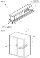
- FIG. 1 is a view showing a schematic configuration of a display device used in the exemplary embodiments.
- FIG. 2 is a view for explaining the mounting member according to the first exemplary embodiment.
- FIG. 3 is a plain view for explaining the regulation member.
- FIG. 4 is a view for explaining a mounting member according to the second exemplary embodiment.
- FIG. 5 is a view for explaining the mounting member according to the third exemplary embodiment.
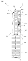
- FIG. 6 is a view for explaining the placement unit of the display device.
- FIG. 7 is a view showing the behavior of the display device and the container on which the mounting member is mounted.
- FIG. 8 is a view for explaining the mounting member according to the fourth exemplary embodiment.
- FIG. 9 is a view for explaining a placement unit of the display device
- FIG. 10 is a view showing the behavior of the display device and the container on which the mounting member is mounted. Description of Embodiments
- FIG. 1 is a view showing a schematic configuration of a display device 30 as an example of a movement mechanism used in the exemplary embodiments.
- FIG. IA is a perspective view for explaining the display device 30, and
- FIG. IB is a perspective view for explaining a display case 10 to which the display device 30 is provided.
- the display device 30 includes: a placement unit 31 on which containers 20, formed as a can, with drink filled therein are placed; and guides 32 that form a moving route of the containers 20, and that guide movement of the containers 20.
- the display device 30 also includes a regulation plate 34 that is formed transparently, arranged along one side of the placement unit 31 and stops movement of the containers 20.
- the display device 30 includes a regulation member 35 that faces the placement unit 31 and that is disposed above the placement unit 31 so as to be separated from the placement unit 31 at a predetermined distance.
- the regulation member 35 regulates the direction of the containers 20 on which mounting members 40 are respectively mounted by being engaged with each mounting member 40 as an example of a lid to be mentioned later.
- the display device 30 is, as shown in FIG. IB, put inside a display case 10 installed in a convenience store, a super market or the like.
- This display case 10 includes: a case main body unit 1OA formed into a rectangular parallelepiped shape, and doors 1OB provided so as to be openable and closable with respect to this case main body unit 1OA, which form a main part of the display case 10.
- a side where the doors 1OB are provided is sometimes referred to as a front side (frontward), whereas the side opposite to the doors 1OB is sometimes referred to as a back side (backward).
- a width direction (a direction orthogonal to a direction in which the containers 20 move) of the display case 10 is sometimes referred to as a lateral direction, or as a width direction.
- the display device 30 is placed on a shelf (not shown in the figure) provided to the inside of the display case 10.
- the display device 30 is placed so that the side thereof where the regulation plate 34 is provided may be located at the side where the doors 1OB are provided.
- the display device 30 is placed so that the side thereof where the regulation plate 34 is provided may be positioned at a lower level than a side opposite to the side where the regulation plate 34 is provided. That is, the display device 30 is arranged in a downward sloping state from a back side of the display case 10 toward a front side thereof (a side of a taken-out portion) from which the containers 20 are taken out.
- the display case 10 in the exemplary embodiments also has a door (not shown in the figure) provided on the back side thereof, whereby the back side becomes also openable.
- the containers 20 are supplied to the display device 30 from this back side. That is, the display case 10 has a configuration where a supplying portion for the containers 20 is provided at the back side of the display case 10, and at the back side of the display device 30. There, the containers 20 having been supplied move on the placement unit 31 toward the doors 1OB. That is, the containers 20 move toward purchasers who purchase the containers 20.
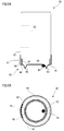
- FIG. 2 is a view for explaining the mounting member 40 according to the first exemplary embodiment.
- FIG. 2A is a plain view of the mounting member 40
- FIG. 2B is a longitudinal sectional view of the mounting member 40 taken along a line IIB - HB of FIG. 2A
- FIG. 2C is a plain view of the mounting member 40 according to a modified example
- FIG. 2D is a view showing a relationship between the container 20 and the mounting member 40 in a state of mounting the mounting member 40 on an upper part of the container 20.
- the mounting member 40 is engaged with the container 20 so as not to move in a circumferential direction of the container 20 when mounted on the container 20.
- a so- called two-piece can is illustrated as an example of the container 20. However, the same is applicable to a three-piece can.
- the mounting member 40 shown in FIGs. 2 A and 2B is a molded component formed into a cap, and is to be mounted on the container 20 as shown in FIG. 2D.
- the mounting member 40 includes a body portion 41 that is formed into a circle and an outer circumferential portion 42 that extends from an edge of the body portion 41 in one direction and that is formed into a flange.
- the mounting member 40 also includes a rising portion 43 as an example of a convex portion or a concave portion, which is formed at a central part of the body portion 41 so as to rise in a direction (outward direction of the mounting member 40) opposite to the extending direction of the outer circumferential portion 42.
- the mounting member 40 includes an upright wall portion 44 that is annularly formed.
- the upright wall portion 44 is formed to extend from the edge of the body portion 41 in the same direction as the outer circumferential portion 42, and to have an outer diameter smaller than that of the outer circumferential portion 42.
- the mounting member 40 includes space 45 formed by the body portion 41, the rising portion 43 and the upright wall portion 44, and space 46 formed by the body portion 41, the outer circumferential portion 42 and the upright wall portion 44.
- the space 45 is shut tightly. Therefore, the space 45 may be utilized for a place in which a product as a free gift is contained.
- the space 46 is narrower than the space 45, and the position thereof is difficult to be seen by a purchaser of the container 20. Therefore, the space 46 may be utilized for a place in which IC chip or the like in which a various kind of information for managing the container 20 is contained, for example.
- the rising portion 43 is formed by a long-shaped portion including a central part and extending in a direction of a diameter (longitudinal direction). Specifically, in an example shown in FIG. 2A, the rising portion 43 is approximately an ellipse when seen as a plain view. On the other hand, in an example shown in FIG. 2C, the rising portion 43 is approximately a diamond shape when seen as a plain view. As shown in FIG. 2D, the container 20 has two identification marks 23 on a side portion 22. More specifically, the identification marks 23 are provided on positions of the side portion 22, the positions corresponding to the longitudinal direction of the rising portion 43.
- the rising portion 43 is provided so as to be biased on one side (right side in FIGs. 2A and 2C) with respect to the center in the longitudinal direction.
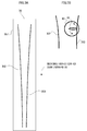
- FIG. 3 is a plain view for explaining the regulation member 35.
- FIG. 3A is a plain view of the regulation member 35
- FIG. 3B is a plain view for explaining an action when the mounting member 40 mounted on the container 20 makes contact with the regulation member 35.
- the regulation member 35 includes a body portion 351, projecting portions 352 and 353 continuously projecting from respective sides of the body portion 351.
- the projecting portions 352 and 353 are arranged so as to have a separation distance that becomes narrower as proceeding in the moving direction of the containers 20.
- the projecting portions 352 and 353 are engaged with the rising portion 43 of the mounting member 40, and regulate a direction with respect to the moving direction of the containers 20 moving in the moving direction. That is, the container 20 is regulated so that the longitudinal direction of the rising portion 43 is directed to the moving direction of the containers 20 on a downstream side in the moving direction where the separation distance between the projecting portions 352 and 353 is small.
- any one of the two identification marks 23 of the container 20 faces a front side in the moving direction, at the taken-out portion for the containers 20 (refer to FIG. 1). More specifically, when the rising portion 43 of the mounting member 40 enters the regulation member 35 in a lateral state as described in FIG. 3B, the container 20 rotates in an arrow direction by the engagement between the rising portion 43 and the projecting portion 353, and thus the container 20 moves in the moving direction smoothly.
- FIG. 4 is a view for explaining a mounting member 40 according to the second exemplary embodiment.
- FIG. 4A is a view showing a relationship between the container 20 and the mounting member 40 in a state where the mounting member 40 is mounted on a lower portion (bottom portion) of the container 20, and
- FIG. 4B is a plain view for explaining the placement unit 36.
- the mounting member 40 is attached to the lower portion of the container 20.
- the mounting member 40 according to the second exemplary embodiment has the same structure as the above-mentioned first exemplary embodiment, and thus the description thereof may be omitted in some cases.
- the placement unit 36 according to the second exemplary embodiment corresponds to the placement unit 31 according to the first exemplary embodiment.
- the placement unit 36 includes a body portion 361, and guide portions 362 and 363 that guide the mounting member 40 by continuously projecting from respective sides of the body portion 361 to be engaged with the rising portion 43 of the mounting member 40.
- the guide portions 362 and 363 correspond to the projecting portions 352 and 353 of the regulation member 35 according to the first exemplary embodiment. That is, the guide portions 362 and 363 are arranged so as to have a separation distance that becomes narrower as proceeding in the moving direction of the containers 20.
- the placement unit 36 includes multiple roll members 364 and 365 that are provided so as to rotate along the moving direction of the containers 20. These roll members 364 and 365 are arranged along the moving direction (front-back direction) of the container 20. The roll members 364 and 365 support the container 20 on which the mounting member 40 is mounted, by making contact with the body portion 41 of the mounting member 40.
- a cylindrical container 20 is illustrated as an example.
- the container 20 may be configured as a so-called bottle can whose diameter is reduced at the upper portion of the container 20.
- Third exemplary embodiment Next, a description will be given of the third exemplary embodiment. First, a mounting member 40 according to the third exemplary embodiment will be explained.
- FIG. 5 is a view for explaining the mounting member 40 according to the third exemplary embodiment.
- FIG. 5A is a view showing a relationship between the container 20 and the mounting member 40 in a state where the mounting member 40 is mounted on the bottom portion 21 of the container 20, and
- FIG. 5B is the bottom view of FIG. 5A.
- the mounting member 40 according to the third exemplary embodiment has a basic structure same as that of the mounting member 40 according to the first exemplary embodiment, and thus the description of the same items may be omitted in some cases.
- a rising portion 43 as an example of a holding portion, provided to the mounting member 40 is formed into an annular rib shape.
- the mounting member 40 includes a projecting portion 47 that is made of resin and formed on an inner circumferential side of the rising portion 43.
- formation of the projecting portion 47 with resin may be performed, for example, by welding the projecting portion 47 to each of the containers 20 by use of a device (for example, a thermal ejection gun) which fuses and ejects thermoplastic resin represented by epoxy- based resin or the like.
- the projecting portion 47 may be integrally formed with the mounting member 40. Note that, when being sold, the containers 20 may be subjected to warming or the like in some cases. For this reason, it is preferable that resin not melting at a temperature to which the containers 20 are warmed when being sold should be selected as the resin used for the projecting portion 47.
- the mounting member 40 is mounted on the container 20 so that the projecting portion 47 of the mounting member 40 is positioned on a side opposed to a position where the identification mark 23 of the container 20 is placed, as shown in FIG. 5A. That is, the relative position between the projecting portion 47 of the mounting member 40 and the identification mark 23 of the container 20 in the circumferential direction is determined.
- the display device 30 (refer to FIG. 1) according to the third exemplary embodiment will be described further in detail.
- FIG. 6 is a view for explaining the placement unit 31 of the display device 30.
- FIG. 6A is a plain view of the placement unit 31
- FIG. 6B is a side view of the placement unit 31.
- the placement unit 31 includes: a first roller portion 311; and a resistance application portion 312 which applies sliding resistance (frictional resistance) to the containers 20 by making contact with bottom portions (end portions) 21 of the containers 20. Additionally, the placement unit 31 includes a rotation stopping mechanism 313 that is arranged between the first roller portion 311 and the resistance application portion 312, and that stops rotation of the containers 20 (which will be described later in detail). As described above, the placement unit 31 is configured by a mechanism including a rotation mechanism that rotates the containers 20 and the rotation stopping mechanism 313 that stops the rotation of the containers 20.
- the first roller portion 311, the resistance application portion 312 and the rotation stopping mechanism 313 are arranged side by side in the lateral direction. Additionally, in front of the first roller portion 311, the resistance application portion 312 and the rotation stopping mechanism 313, the placement unit 31 includes a second roller portion 314 which moves the containers 20 further frontward.
- the first roller portion 311 has plural roll- shaped members 311a provided so as to be rotatable along the moving direction of the containers 20. Note that these roll-shaped members 31 Ia are arrayed along the moving direction (a front-back direction) of the containers 20.
- the resistance application portion 312 may be formed of, for example, a rubber member.
- EPDM ethylene-propylene rubber
- EPDM ethylene-propylene rubber
- the second roller portion 314 has plural roll-shaped members 314a provided so as to be rotatable along the moving direction of the containers 20.
- the plural roll- shaped members 314a are arrayed along the moving direction of the containers 20.
- the roll-shaped members 314a are arranged in two lines located side by side in the width direction.
- each of the roll-shaped members 314a is formed wider in width than each of the roll-shaped members 31 Ia in the first roller portion 311.
- the rotation stopping mechanism 313 includes a belt member 313a that is formed into an endless shape and that is circularly movable. Additionally, the rotation stopping mechanism 313 includes a first stretching roll 313b and a second stretching roll 313c that are provided so as to be rotatable, and that suspend the belt member 313a in a tensioned state from inside of the belt member 313a. Additionally, the rotation stopping mechanism 313 includes plural moving members 313d that are provided to be fixed to a surface of the belt member 313a and arrayed along a moving direction of the belt member 313a, and that make a circular movement along with the movement of the belt member 313a.
- the rotation stopping mechanism 313 includes plural protrusions 313e that are provided at predetermined intervals in the moving direction of the belt member 313a, and that project from surfaces of the moving members 313d.
- the protrusions 313e are provided so as to project toward the containers 20 placed on the placement unit 31 farther than positions at which the lowest end portions of the containers 20 come into contact with the moving members 313d (the placement unit 31).
- FIG. 7 is a view showing the behavior of the display device 30 and the container 20 on which the mounting member 40 is mounted.
- the container 20 rotates clockwise (in a circumferential direction thereof) while moving frontward. That is, resistance force acting against movement force which forces the container 20 to move frontward becomes different depending on section of the container 20, whereby the container 20 rotates. In detail, resistance force acting on the left and right sides of the container 20 with respect to the gravity center thereof becomes different, whereby the container 20 rotates together with the mounting member 40. [0029] Thereafter, the projecting portion 47 of the mounting member 40 is engaged with the one of the protrusions 313e of the rotation stopping mechanism 313. Thereby, rotation of the mounting member 40 and the container 20 is stopped (regulated) (refer to a broken line 4C).
- the identification mark 23 comes to face frontward at the stage when the container 20 reaches the front. For this reason, even if placement (supply) of the container 20 is made without the identification mark 23 facing frontward, the identification mark 23 ends up facing frontward when the container 20 reaches the front side of the display case 10 (refer to FIG. IB). That is, even if a supplier who supplies the containers 20 to the display device 30 does not perform any particular operations, the identification marks 23 may face frontward.
- FIG. 8 (FIGs. 8A and 8B) is a view for explaining the mounting member 40 according to the fourth exemplary embodiment.
- FIG. 8A is a view showing a relationship between the container 20 and the mounting member 40 in a state where the mounting member 40 is mounted on the lower portion of the container 20, and
- FIG. 8B is the bottom view of FIG. 8A.
- FIG. 8 is a drawing corresponding to FIG. 5 in which the third exemplary embodiment is illustrated.
- the mounting member 40 according to the fourth exemplary embodiment has a basic structure same as that of the mounting member 40 according to the third exemplary embodiment, and thus the description of the same items may be omitted in some cases. As shown in FIGs.
- the mounting member 40 includes a rising portion 43 formed into an annular rib shape, and a first concave portion 48a and a second concave portion 48b are formed on an outer circumferential face (outer side) of the rising portion 43.
- the first concave portion 48a and the second concave portion 48b are arranged so as to be opposed to each other.
- the first concave portion 48a and the second concave portion 48b are arranged so that phases thereof may be shifted by 180 degrees in a circumferential direction of the container 20. Note that, in the patent description of the present invention, such concave portions formed on the container 20 are sometimes referred to simply as concave portions 48.
- the container 20 has, in specific portions on the side portion 22 which is a part of an outer face thereof, a first identification mark 23a and a second identification mark 23b, each of which is a trade name, a trademark or the like, used for differentiating a product from other products.
- a first identification mark 23a and a second identification mark 23b each of which is a trade name, a trademark or the like, used for differentiating a product from other products.
- each of the first identification mark 23a and the second identification mark 23b is sometimes referred to simply as "an identification mark 23.”
- the first identification mark 23a and the second identification mark 23b may be the same configuration, or different configurations.
- the first identification mark 23a and the second identification mark 23b are arranged so that phases thereof may be shifted by 180 degrees in the circumferential direction of the container 20.
- the first identification mark 23a and the first concave portion 48a are arranged so that phases thereof may be shifted by 90 degrees in the circumferential direction of the container 20. Additionally, the second identification mark 23b and the second concave portion 48b are also arranged so that phases thereof may be shifted by 90 degrees. That is, while the first identification mark 23a and the first concave portion 48a are formed so as to have a predetermined positional relationship, the second identification mark 23b and the second concave portion 48b are also formed so as to have a predetermined positional relationship. In further description, the first identification mark 23a and the first concave portion 48a are arranged in positions different from each other, and the second identification mark 23b and the second concave portion 48b are also arranged in positions different from each other.
- the first identification mark 23a and the second identification mark 23b are arranged so that phases thereof may be shifted by 180 degrees.
- the first concave portion 48a and the second concave portion 48b are arranged so that phases thereof may be shifted by 180 degrees.
- the concave portions 48 are provided so as to correspond to these respective identification marks 23.
- FIG. 9 is a view for explaining a placement unit 31 of the display device 30.
- FIG. 9A is a plain view of the placement unit 31
- FIG. 9B is a side view of the rotation stopping mechanism 313
- FIG. 9C is a view showing a state when the display device 30 is seen from the front side.
- the back side (an upper side in the figure) of the placement unit 31 is arranged in such a sloping state that, in the width direction, a side of one end portion (one side) may be positioned lower than a side of the other end portion (the other side).
- the back side of the placement unit 31 is arranged in such a sloping state that a side thereof closer to the guide 32 is positioned lower than a side thereof opposite to the side closer to the guide 32.
- the front side (specifically, a front side located in front of the guide 32) of the placement unit 31 is not provided with slope in the width direction.
- a triangle and a rectangle indicated by reference numerals 1 IA and 1 IB in FIG. 9 A indicate sloping states of the back side and the front side of the placement unit 31, respectively.
- the rotation stopping mechanism 313 is arranged on the side of the moving route instead of the position directly below the moving route of the containers 20.
- the rotation stopping mechanism 313 shown in FIGs. 9A to 9C is configured to have the protrusions 313e projecting in the width direction of the rotation stopping mechanism 313 instead of projecting upward.
- the protrusions 313e are configured to project in a direction orthogonal to (a direction intersecting with) the moving direction of the containers 20. That is, the protrusions 313e are configured to project from the lateral side of the moving route of the containers 20 onto the moving route.
- the rotation stopping mechanism 313 includes plural rod-shaped members 313j that projects onto the moving route of the containers 20, enters between each adjacent ones of the containers 20, and thereby prevents mutual contact between the corresponding containers 20.
- the identification mark 23 and the projecting portion 47 of each of the containers 20 used in the display device 30 are, as indicated by reference numeral 17 A in FIG. 10, arranged so that phases may be shifted by 90 degrees in the circumferential direction of the container 20.
- the container 20 (refer to reference numeral 17A) placed on the back side of the display device 30 moves frontward while being guided by the guide 32.
- the container 20 moves frontward while rotating counterclockwise by receiving rotational force from the guide 32 (refer to reference numeral 17B).
- the container 20 goes into a state where the first concave portion 48a thereof and one of the protrusions 313e are engaged with each other, and thus rotation of the container 20 is stopped (refer to reference numeral 17C).
- the container 20 is in a state where the first identification mark 23a faces frontward.
- the container 20 after passing through the rotation stopping mechanism 313, the container 20 further moves frontward, and is then stopped at a predetermined position with the first identification mark 23 a facing frontward (refer to reference numeral 17D).
- the identification marks 23 are positioned so as to be in one direction while the containers 20 move frontward on the display device 30.
- the identification marks 23 of the containers 20 faces the front side in the moving direction.
Landscapes
- Engineering & Computer Science (AREA)
- Mechanical Engineering (AREA)
- Details Of Rigid Or Semi-Rigid Containers (AREA)
Abstract
There are provided mounting members and lidded containers allowing the containers to be displayed with marks on them facing a predetermined direction even if they are placed with the marks facing random directions, when they are displayed so as to stand upright on a display device. The mounting member 40 is a molded component formed into a cap, and is to be mounted on the container 20. The mounting member 40 includes a circular body portion 41, a flange-shaped outer circumferential portion 42 extending from an edge of the body portion 41 in one direction, and a rising portion 43 formed at a central part of the body portion 41 so as to rise in an opposite direction to the extending direction of the outer circumferential portion 42. The rising portion 43 is formed by a long-shaped portion including a central part and extending in a direction of a diameter.
Description
The present invention relates to mounting members and lidded containers, which are applied to a display system that displays the containers, or the like.
When being sold, for example, in a convenience store, containers, such as drink cans and PET bottles, filled with drink are placed to stand upright on a display device put, for example, in a display case. There, the display device as described above is arranged, for example, in a sloping state so that each container may move frontward in the display case due to its own weight. When one container at a front side (in the front row) is taken out, other containers following that container move toward the front side due to their own weight.
Here, for example, a plastic flat plate is provided, because of good sliding of containers, to a part on which the containers are placed in the display device. Meanwhile, a display device in which a large number of rotatable rollers are arranged has become available in recent years (for example, refer to Patent Literature 1). Additionally, although containers are supplied from a back side of a display device in general, there is proposed a display device allowing containers to be supplied from a front side, and allowing a container, which has moved backward, to move to the front side again so as to be displayed (for example, refer to Patent Literature 2). That is, there is proposed a display device in which a container supplied from a front side makes a U-turn and returns. Furthermore, with regard to a container, there has been proposed a can having inside concave portions and vertical ribs alternately formed, in a circumferential direction, in an inner circumferential wall of an annular convex portion formed on a bottom of the can (for example, refer to Patent Literature 3).
Here, for example, a plastic flat plate is provided, because of good sliding of containers, to a part on which the containers are placed in the display device. Meanwhile, a display device in which a large number of rotatable rollers are arranged has become available in recent years (for example, refer to Patent Literature 1). Additionally, although containers are supplied from a back side of a display device in general, there is proposed a display device allowing containers to be supplied from a front side, and allowing a container, which has moved backward, to move to the front side again so as to be displayed (for example, refer to Patent Literature 2). That is, there is proposed a display device in which a container supplied from a front side makes a U-turn and returns. Furthermore, with regard to a container, there has been proposed a can having inside concave portions and vertical ribs alternately formed, in a circumferential direction, in an inner circumferential wall of an annular convex portion formed on a bottom of the can (for example, refer to Patent Literature 3).
An outer face of a container is provided with a mark, such as a trade name or a trademark, in order to differentiate a product from other products. If this mark does not face a side from which a purchaser takes out the container, it is difficult to identify the product, and also the product does not look good when being displayed. For this reason, it is preferable that marks on displayed containers face a predetermined direction which is, for example, a front direction or the like.
As a conventional technique described in the official gazettes, there has been proposed a display method (for example, refer to Patent Literature 4) in which: on an upper face of a sloping shelf plate on which containers are placed, a rod-shaped guide ridge is provided to extend in a sloping direction of the shelf plate; on a bottom portion of each container, a concave fitting portion is provided to connect a position directly under a mark to a position directly under a face opposite to a face where the mark is attached; and the container is displayed by use of this guide ridge and this concave fitting portion. In this display method, plural containers are aligned in a front-back direction by having the concave fitting portions fit to the guide ridge with each of those containers put in such a position that the mark faces frontward. As a result, the containers are displayed with the marks facing frontward.
In Patent Literature 4 mentioned above, by performing display of the containers with the concave fitting portions being fit to the guide ridge, the marks are reliably faced frontward. In this invention, however, a supplier of the containers is required to fit the concave fitting portions to the guide ridge every time the supplier puts the container on a display device, and this makes displaying work of the containers troublesome. Additionally, in a case where the mark is formed on only one part of each of the containers, it is feared that there may occur a display failure where some of the containers are displayed with the marks facing backward. Additionally, in a store or the like, such as a convenience store, where a large number of drinks are sold, work of supplying the containers in a way to make the containers face the same direction is very extensive.
A main object of the present invention is to provide mounting members and containers with lids which, when the containers are displayed so as to stand upright on the display device, allow the containers to be displayed with marks thereon facing a predetermined direction even if the containers are placed with the marks facing random directions.
In order to attain the above object, a system to which the present invention is applied is a display system that rotates a container as appropriate in a movement process from the first position to the second position, and that makes a mark of the container face a specific direction after the container is moved to the second position. Moreover, a mounting member to which the present invention is applied is a mounting member mounted on a container having a mark attached thereon, the mounting member including: any one of a convex portion and a concave portion that is used when the mark of the container is caused to face a predetermined direction, the container moving with the mark facing a direction other than the predetermined direction.
Here, the mark of the container is caused to face the predetermined direction by engaging any one of the convex portion and the concave portion with a movement mechanism for movement of the container. Moreover, the mounting member includes, as the convex portion, a long-shaped portion that extends in a direction of a diameter and that is provided on an outer face. In addition, the mounting member is mounted on a bottom portion of the container, the mounting member further includes a holding portion that is annular and holds the container, and any one of the convex portion and the concave portion is formed on any one of an inner side and an outer side of the holding portion. Further, space is formed between the mounting member and an outer face of the container when the mounting member is mounted on the container.
According to another aspect of the present invention, a mounting member to which the present invention is applied is a mounting member mounted on a container having a mark attached thereon, the mounting member including: any one of a convex portion and a concave portion that is used when the container having been rotated is stopped with the mark facing a predetermined direction.
Here, the mark of the container is caused to face the predetermined direction by engaging any one of the convex portion and the concave portion with a mechanism including a rotation mechanism that rotates the container and a rotation stopping mechanism that stops the rotation of the container. Moreover, the mounting member is mounted on a bottom portion of the container, the mounting member further includes a holding portion that is annular and holds the container, and any one of the convex portion and the concave portion is formed on any one of an inner side and an outer side of the holding portion.
According to a further aspect of the present invention, there is provided a lidded container to which the present invention is applied includes: a container that has a mark attached thereon; a lid that has any one of a concave portion and a convex portion that is used when the container having been rotated is stopped with the mark facing a predetermined direction. The mark of the container and any one of the convex portion and the concave portion of the lid have a positional relationship set in advance.
According to the present invention, it is possible to allow the containers to be displayed with marks thereon facing a predetermined direction even if the containers are placed with the marks facing random directions when the containers are displayed so as to stand upright on the display device.
Exemplary embodiments of the present invention will be described below in detail with reference to the accompanying drawings.
FIG. 1 (FIGs. 1A and 1B) is a view showing a schematic configuration of adisplay device 30 as an example of a movement mechanism used in the exemplary embodiments. FIG. 1A is a perspective view for explaining the display device 30, and FIG. 1B is a perspective view for explaining a display case 10 to which the display device 30 is provided.
As shown in FIG. 1A, thedisplay device 30 according to the exemplary embodiments includes: a placement unit 31 on which containers 20, formed as a can, with drink filled therein are placed; and guides 32 that form a moving route of the containers 20, and that guide movement of the containers 20.
Thedisplay device 30 also includes a regulation plate 34 that is formed transparently, arranged along one side of the placement unit 31 and stops movement of the containers 20. In addition, the display device 30 includes a regulation member 35 that faces the placement unit 31 and that is disposed above the placement unit 31 so as to be separated from the placement unit 31 at a predetermined distance. The regulation member 35 regulates the direction of the containers 20 on which mounting members 40 are respectively mounted by being engaged with each mounting member 40 as an example of a lid to be mentioned later.
FIG. 1 (FIGs. 1A and 1B) is a view showing a schematic configuration of a
As shown in FIG. 1A, the
The
The display device 30 is, as shown in FIG. 1B, put inside a display case 10 installed in a convenience store, a super market or the like. This display case 10 includes: a case main body unit 10A formed into a rectangular parallelepiped shape, and doors 10B provided so as to be openable and closable with respect to this case main body unit 10A, which form a main part of the display case 10. Note that, in this patent description of the present invention, a side where the doors 10B are provided is sometimes referred to as a front side (frontward), whereas the side opposite to the doors 10B is sometimes referred to as a back side (backward). Additionally, a width direction (a direction orthogonal to a direction in which the containers 20 move) of the display case 10 is sometimes referred to as a lateral direction, or as a width direction.
Here, thedisplay device 30 is placed on a shelf (not shown in the figure) provided to the inside of the display case 10. On this occasion, the display device 30 is placed so that the side thereof where the regulation plate 34 is provided may be located at the side where the doors 10B are provided. Additionally, the display device 30 is placed so that the side thereof where the regulation plate 34 is provided may be positioned at a lower level than a side opposite to the side where the regulation plate 34 is provided. That is, the display device 30 is arranged in a downward sloping state from a back side of the display case 10 toward a front side thereof (a side of a taken-out portion) from which the containers 20 are taken out.
Here, the
Here, the display case 10 in the exemplary embodiments also has a door (not shown in the figure) provided on the back side thereof, whereby the back side becomes also openable. The containers 20 are supplied to the display device 30 from this back side. That is, the display case 10 has a configuration where a supplying portion for the containers 20 is provided at the back side of the display case 10, and at the back side of the display device 30. There, the containers 20 having been supplied move on the placement unit 31 toward the doors 10B. That is, the containers 20 move toward purchasers who purchase the containers 20.
FIG. 2 (FIGs. 2A to 2D) is a view for explaining the mounting member 40 according to the first exemplary embodiment. FIG. 2A is a plain view of the mounting member 40, FIG. 2B is a longitudinal sectional view of the mounting member 40 taken along a line IIB - IIB of FIG. 2A, FIG. 2C is a plain view of the mounting member 40 according to a modified example, and FIG. 2D is a view showing a relationship between the container 20 and the mounting member 40 in a state of mounting the mounting member 40 on an upper part of the container 20. Note that, the mounting member 40 is engaged with the container 20 so as not to move in a circumferential direction of the container 20 when mounted on the container 20. In FIG. 2D, a so-called two-piece can is illustrated as an example of the container 20. However, the same is applicable to a three-piece can.
The mountingmember 40 shown in FIGs. 2A and 2B is a molded component formed into a cap, and is to be mounted on the container 20 as shown in FIG. 2D. The mounting member 40 includes a body portion 41 that is formed into a circle and an outer circumferential portion 42 that extends from an edge of the body portion 41 in one direction and that is formed into a flange. The mounting member 40 also includes a rising portion 43 as an example of a convex portion or a concave portion, which is formed at a central part of the body portion 41 so as to rise in a direction (outward direction of the mounting member 40) opposite to the extending direction of the outer circumferential portion 42. In addition, the mounting member 40 includes an upright wall portion 44 that is annularly formed. Here, the upright wall portion 44 is formed to extend from the edge of the body portion 41 in the same direction as the outer circumferential portion 42, and to have an outer diameter smaller than that of the outer circumferential portion 42.
The mounting
In further description, the mounting member 40 includes space 45 formed by the body portion 41, the rising portion 43 and the upright wall portion 44, and space 46 formed by the body portion 41, the outer circumferential portion 42 and the upright wall portion 44. When the mounting member 40 is mounted on the container 20, the space 45 is shut tightly. Therefore, the space 45 may be utilized for a place in which a product as a free gift is contained. On the other hand, the space 46 is narrower than the space 45, and the position thereof is difficult to be seen by a purchaser of the container 20. Therefore, the space 46 may be utilized for a place in which IC chip or the like in which a various kind of information for managing the container 20 is contained, for example.
Here, the rising portion 43 according to the first exemplary embodiment is formed by a long-shaped portion including a central part and extending in a direction of a diameter (longitudinal direction). Specifically, in an example shown in FIG. 2A, the rising portion 43 is approximately an ellipse when seen as a plain view. On the other hand, in an example shown in FIG. 2C, the rising portion 43 is approximately a diamond shape when seen as a plain view. As shown in FIG. 2D, the container 20 has two identification marks 23 on a side portion 22. More specifically, the identification marks 23 are provided on positions of the side portion 22, the positions corresponding to the longitudinal direction of the rising portion 43.
In addition, the risingportion 43 is provided so as to be biased on one side (right side in FIGs. 2A and 2C) with respect to the center in the longitudinal direction.
In addition, the rising
FIG. 3 (FIGs. 3A and 3B) is a plain view for explaining the regulation member 35. FIG. 3A is a plain view of the regulation member 35, and FIG. 3B is a plain view for explaining an action when the mounting member 40 mounted on the container 20 makes contact with the regulation member 35.
As shown in FIG. 3A, theregulation member 35 includes a body portion 351, projecting portions 352 and 353 continuously projecting from respective sides of the body portion 351. The projecting portions 352 and 353 are arranged so as to have a separation distance that becomes narrower as proceeding in the moving direction of the containers 20. The projecting portions 352 and 353 are engaged with the rising portion 43 of the mounting member 40, and regulate a direction with respect to the moving direction of the containers 20 moving in the moving direction. That is, the container 20 is regulated so that the longitudinal direction of the rising portion 43 is directed to the moving direction of the containers 20 on a downstream side in the moving direction where the separation distance between the projecting portions 352 and 353 is small. Since a positional relationship between the rising portion 43 of the mounting member 40 and the identification marks 23 of the container 20 is determined as described above, any one of the two identification marks 23 of the container 20 faces a front side in the moving direction, at the taken-out portion for the containers 20 (refer to FIG. 1).
More specifically, when the risingportion 43 of the mounting member 40 enters the regulation member 35 in a lateral state as described in FIG. 3B, the container 20 rotates in an arrow direction by the engagement between the rising portion 43 and the projecting portion 353, and thus the container 20 moves in the moving direction smoothly.
As shown in FIG. 3A, the
More specifically, when the rising
FIG. 4 (FIGs. 4A and 4B) is a view for explaining a mounting member 40 according to the second exemplary embodiment. FIG. 4A is a view showing a relationship between the container 20 and the mounting member 40 in a state where the mounting member 40 is mounted on a lower portion (bottom portion) of the container 20, and FIG. 4B is a plain view for explaining the placement unit 36.
As shown in FIG. 4A, in the second exemplary embodiment, the mountingmember 40 is attached to the lower portion of the container 20. Note that, the mounting member 40 according to the second exemplary embodiment has the same structure as the above-mentioned first exemplary embodiment, and thus the description thereof may be omitted in some cases. The placement unit 36 according to the second exemplary embodiment corresponds to the placement unit 31 according to the first exemplary embodiment.
As shown in FIG. 4B, theplacement unit 36 includes a body portion 361, and guide portions 362 and 363 that guide the mounting member 40 by continuously projecting from respective sides of the body portion 361 to be engaged with the rising portion 43 of the mounting member 40. The guide portions 362 and 363 correspond to the projecting portions 352 and 353 of the regulation member 35 according to the first exemplary embodiment. That is, the guide portions 362 and 363 are arranged so as to have a separation distance that becomes narrower as proceeding in the moving direction of the containers 20.
In addition, theplacement unit 36 includes multiple roll members 364 and 365 that are provided so as to rotate along the moving direction of the containers 20. These roll members 364 and 365 are arranged along the moving direction (front-back direction) of the container 20. The roll members 364 and 365 support the container 20 on which the mounting member 40 is mounted, by making contact with the body portion 41 of the mounting member 40.
Note that, in the second exemplary embodiment, acylindrical container 20 is illustrated as an example. However, the container 20 may be configured as a so-called bottle can whose diameter is reduced at the upper portion of the container 20.
As shown in FIG. 4A, in the second exemplary embodiment, the mounting
As shown in FIG. 4B, the
In addition, the
Note that, in the second exemplary embodiment, a
Next, a description will be given of the third exemplary embodiment. First, a mounting member 40 according to the third exemplary embodiment will be explained.
FIG. 5 (FIGs. 5A and 5B) is a view for explaining the mountingmember 40 according to the third exemplary embodiment. FIG. 5A is a view showing a relationship between the container 20 and the mounting member 40 in a state where the mounting member 40 is mounted on the bottom portion 21 of the container 20, and FIG. 5B is the bottom view of FIG. 5A. Note that, the mounting member 40 according to the third exemplary embodiment has a basic structure same as that of the mounting member 40 according to the first exemplary embodiment, and thus the description of the same items may be omitted in some cases.
As shown in FIGs. 5A and 5B, a risingportion 43 as an example of a holding portion, provided to the mounting member 40, is formed into an annular rib shape. The mounting member 40 includes a projecting portion 47 that is made of resin and formed on an inner circumferential side of the rising portion 43. Here, for example, formation of the projecting portion 47 with resin may be performed, for example, by welding the projecting portion 47 to each of the containers 20 by use of a device (for example, a thermal ejection gun) which fuses and ejects thermoplastic resin represented by epoxy-based resin or the like. The projecting portion 47 may be integrally formed with the mounting member 40. Note that, when being sold, the containers 20 may be subjected to warming or the like in some cases. For this reason, it is preferable that resin not melting at a temperature to which the containers 20 are warmed when being sold should be selected as the resin used for the projecting portion 47.
In addition, the mountingmember 40 is mounted on the container 20 so that the projecting portion 47 of the mounting member 40 is positioned on a side opposed to a position where the identification mark 23 of the container 20 is placed, as shown in FIG. 5A. That is, the relative position between the projecting portion 47 of the mounting member 40 and the identification mark 23 of the container 20 in the circumferential direction is determined.
FIG. 5 (FIGs. 5A and 5B) is a view for explaining the mounting
As shown in FIGs. 5A and 5B, a rising
In addition, the mounting
The display device 30 (refer to FIG. 1) according to the third exemplary embodiment will be described further in detail.
FIG. 6 (FIGs. 6A and 6B) is a view for explaining theplacement unit 31 of the display device 30. Here, FIG. 6A is a plain view of the placement unit 31, and FIG. 6B is a side view of the placement unit 31.
As shown in FIG. 6A, on the moving route formed by the guides 32 (not shown in FIG. 6A), theplacement unit 31 includes: a first roller portion 311; and a resistance application portion 312 which applies sliding resistance (frictional resistance) to the containers 20 by making contact with bottom portions (end portions) 21 of the containers 20. Additionally, the placement unit 31 includes a rotation stopping mechanism 313 that is arranged between the first roller portion 311 and the resistance application portion 312, and that stops rotation of the containers 20 (which will be described later in detail). As described above, the placement unit 31 is configured by a mechanism including a rotation mechanism that rotates the containers 20 and the rotation stopping mechanism 313 that stops the rotation of the containers 20.
Here, thefirst roller portion 311, the resistance application portion 312 and the rotation stopping mechanism 313 are arranged side by side in the lateral direction. Additionally, in front of the first roller portion 311, the resistance application portion 312 and the rotation stopping mechanism 313, the placement unit 31 includes a second roller portion 314 which moves the containers 20 further frontward.
FIG. 6 (FIGs. 6A and 6B) is a view for explaining the
As shown in FIG. 6A, on the moving route formed by the guides 32 (not shown in FIG. 6A), the
Here, the
The first roller portion 311 has plural roll-shaped members 311a provided so as to be rotatable along the moving direction of the containers 20. Note that these roll-shaped members 311a are arrayed along the moving direction (a front-back direction) of the containers 20.
Theresistance application portion 312 may be formed of, for example, a rubber member. Note that EPDM (ethylene-propylene rubber), for example, may be used as the rubber member.
Thesecond roller portion 314 has plural roll-shaped members 314a provided so as to be rotatable along the moving direction of the containers 20. Here, the plural roll-shaped members 314a are arrayed along the moving direction of the containers 20. Additionally, the roll-shaped members 314a are arranged in two lines located side by side in the width direction. Furthermore, each of the roll-shaped members 314a is formed wider in width than each of the roll-shaped members 311a in the first roller portion 311.
The
The
As shown in FIG. 6B, the rotation stopping mechanism 313 includes a belt member 313a that is formed into an endless shape and that is circularly movable. Additionally, the rotation stopping mechanism 313 includes a first stretching roll 313b and a second stretching roll 313c that are provided so as to be rotatable, and that suspend the belt member 313a in a tensioned state from inside of the belt member 313a. Additionally, the rotation stopping mechanism 313 includes plural moving members 313d that are provided to be fixed to a surface of the belt member 313a and arrayed along a moving direction of the belt member 313a, and that make a circular movement along with the movement of the belt member 313a. Furthermore, the rotation stopping mechanism 313 includes plural protrusions 313e that are provided at predetermined intervals in the moving direction of the belt member 313a, and that project from surfaces of the moving members 313d. Here, the protrusions 313e are provided so as to project toward the containers 20 placed on the placement unit 31 farther than positions at which the lowest end portions of the containers 20 come into contact with the moving members 313d (the placement unit 31).
Next, a description will be given of behavior of the display device 30 and each of the containers 20 on which the mounting member 40 is mounted when the container 20 is placed on the placement unit 31 of the display device 30.
Here, FIG. 7 is a view showing the behavior of thedisplay device 30 and the container 20 on which the mounting member 40 is mounted.
As shown by asolid line 4A in FIG. 7, when the container 20 on which the mounting member 40 is mounted at the lower portion thereof is placed at the back side of the display device 30, the rising portion 43 (refer to FIG. 5) makes contact with one of the protrusions 313e. Thereby, a load is applied on the rotation stopping mechanism 313 from the container 20 through the mounting member 40, and the moving members 313d included in the rotation stopping mechanism 313 move frontward. At this time, while a right-hand side of the container 20 in the figure is forced by the first roller portion 311 to smoothly move frontward, a left-hand side thereof in the figure is regulated in frontward movement because resistance is applied to the left-hand side by the resistance application portion 312.
Here, FIG. 7 is a view showing the behavior of the
As shown by a
As a result, as shown by a broken line 4B, the container 20 rotates clockwise (in a circumferential direction thereof) while moving frontward. That is, resistance force acting against movement force which forces the container 20 to move frontward becomes different depending on section of the container 20, whereby the container 20 rotates. In detail, resistance force acting on the left and right sides of the container 20 with respect to the gravity center thereof becomes different, whereby the container 20 rotates together with the mounting member 40.
Thereafter, the projecting portion 47 of the mounting member 40 is engaged with the one of the protrusions 313e of the rotation stopping mechanism 313. Thereby, rotation of the mounting member 40 and the container 20 is stopped (regulated) (refer to a broken line 4C). Then, when the mounting member 40 and the container 20 reach a predetermined position of the second roller portion 314, the projecting portion 47 of the mounting member 40 and the protrusion 313e of the rotation stopping mechanism 313 go into a non-contact state. Thereby, the container 20 is further moved frontward together with the mounting member 40, by the second roller portion 314 (refer to a broken line 4D).
In the third exemplary embodiment, as shown by the solid line 4A, for example, even if each of the containers 20 with the mounting member 40 is placed on the placement unit 31 with the identification mark 23 facing backward, the identification mark 23 comes to face frontward at the stage when the container 20 reaches the front. For this reason, even if placement (supply) of the container 20 is made without the identification mark 23 facing frontward, the identification mark 23 ends up facing frontward when the container 20 reaches the front side of the display case 10 (refer to FIG. 1B). That is, even if a supplier who supplies the containers 20 to the display device 30 does not perform any particular operations, the identification marks 23 may face frontward.
Note that, in the third exemplary embodiment, a configuration example in which the projectingportion 47 is provided to the mounting member 40 has been explained, but another configuration example may be considered. For example, there is a configuration example in which a concave portion (not shown in the figure) is provided on the inner circumferential surface of the rising portion 43, instead of the projecting portion 47.
Note that, in the third exemplary embodiment, a configuration example in which the projecting
Next, a description will be given of the fourth exemplary embodiment. First, a mounting member 40 according to the fourth exemplary embodiment will be explained.
FIG. 8 (FIGs. 8A and 8B) is a view for explaining the mountingmember 40 according to the fourth exemplary embodiment. FIG. 8A is a view showing a relationship between the container 20 and the mounting member 40 in a state where the mounting member 40 is mounted on the lower portion of the container 20, and FIG. 8B is the bottom view of FIG. 8A. Note that, FIG. 8 is a drawing corresponding to FIG. 5 in which the third exemplary embodiment is illustrated. In addition, the mounting member 40 according to the fourth exemplary embodiment has a basic structure same as that of the mounting member 40 according to the third exemplary embodiment, and thus the description of the same items may be omitted in some cases.
As shown in FIGs. 8A and 8B, the mountingmember 40 includes a rising portion 43 formed into an annular rib shape, and a first concave portion 48a and a second concave portion 48b are formed on an outer circumferential face (outer side) of the rising portion 43. Here, the first concave portion 48a and the second concave portion 48b are arranged so as to be opposed to each other. Specifically, the first concave portion 48a and the second concave portion 48b are arranged so that phases thereof may be shifted by 180 degrees in a circumferential direction of the container 20. Note that, in the patent description of the present invention, such concave portions formed on the container 20 are sometimes referred to simply as concave portions 48.
FIG. 8 (FIGs. 8A and 8B) is a view for explaining the mounting
As shown in FIGs. 8A and 8B, the mounting
Furthermore, the container 20 has, in specific portions on the side portion 22 which is a part of an outer face thereof, a first identification mark 23a and a second identification mark 23b, each of which is a trade name, a trademark or the like, used for differentiating a product from other products. Note that, in the patent description of the present invention, each of the first identification mark 23a and the second identification mark 23b is sometimes referred to simply as "an identification mark 23." Here, the first identification mark 23a and the second identification mark 23b may be the same configuration, or different configurations. Note that the first identification mark 23a and the second identification mark 23b are arranged so that phases thereof may be shifted by 180 degrees in the circumferential direction of the container 20.
A description will be given of relationships of the concave portions 48 with the identification marks 23. The first identification mark 23a and the first concave portion 48a are arranged so that phases thereof may be shifted by 90 degrees in the circumferential direction of the container 20. Additionally, the second identification mark 23b and the second concave portion 48b are also arranged so that phases thereof may be shifted by 90 degrees. That is, while the first identification mark 23a and the first concave portion 48a are formed so as to have a predetermined positional relationship, the second identification mark 23b and the second concave portion 48b are also formed so as to have a predetermined positional relationship. In further description, the first identification mark 23a and the first concave portion 48a are arranged in positions different from each other, and the second identification mark 23b and the second concave portion 48b are also arranged in positions different from each other.
In further description, the first identification mark 23a and the second identification mark 23b are arranged so that phases thereof may be shifted by 180 degrees. Similarly, the first concave portion 48a and the second concave portion 48b are arranged so that phases thereof may be shifted by 180 degrees. Additionally, in the fourth exemplary embodiment, while the plural identification marks 23 such as the first identification mark 23a and the second identification mark 23b are provided, the concave portions 48 (the first concave portion 48a and the second concave portion 48b) are provided so as to correspond to these respective identification marks 23.
Next, a display device 30 (refer to FIG. 1) used in the fourth exemplary embodiment will be described in detail.
FIG. 9 (FIGs. 9A to 9C) is a view for explaining aplacement unit 31 of the display device 30. FIG. 9A is a plain view of the placement unit 31, FIG. 9B is a side view of the rotation stopping mechanism 313, and FIG. 9C is a view showing a state when the display device 30 is seen from the front side.
In FIG. 9, the back side (an upper side in the figure) of theplacement unit 31 is arranged in such a sloping state that, in the width direction, a side of one end portion (one side) may be positioned lower than a side of the other end portion (the other side). In detailed description, the back side of the placement unit 31 is arranged in such a sloping state that a side thereof closer to the guide 32 is positioned lower than a side thereof opposite to the side closer to the guide 32. On the other hand, the front side (specifically, a front side located in front of the guide 32) of the placement unit 31 is not provided with slope in the width direction. Here, a triangle and a rectangle indicated by reference numerals 11A and 11B in FIG. 9A indicate sloping states of the back side and the front side of the placement unit 31, respectively.
Further, as shown in FIG. 9A, therotation stopping mechanism 313 is arranged on the side of the moving route instead of the position directly below the moving route of the containers 20.
FIG. 9 (FIGs. 9A to 9C) is a view for explaining a
In FIG. 9, the back side (an upper side in the figure) of the
Further, as shown in FIG. 9A, the
The rotation stopping mechanism 313 shown in FIGs. 9A to 9C is configured to have the protrusions 313e projecting in the width direction of the rotation stopping mechanism 313 instead of projecting upward. In other words, the protrusions 313e are configured to project in a direction orthogonal to (a direction intersecting with) the moving direction of the containers 20. That is, the protrusions 313e are configured to project from the lateral side of the moving route of the containers 20 onto the moving route.
Additionally, therotation stopping mechanism 313 includes plural rod-shaped members 313j that projects onto the moving route of the containers 20, enters between each adjacent ones of the containers 20, and thereby prevents mutual contact between the corresponding containers 20. Note that the identification mark 23 and the projecting portion 47 of each of the containers 20 used in the display device 30 are, as indicated by reference numeral 17A in FIG. 10, arranged so that phases may be shifted by 90 degrees in the circumferential direction of the container 20.
Additionally, the
Behavior of the rotation stopping mechanism 313 and each of the containers 20 will be described by use of FIG. 10.
The container 20 (refer to reference numeral 17A) placed on the back side of thedisplay device 30 moves frontward while being guided by the guide 32. Here, on this occasion, the container 20 moves frontward while rotating counterclockwise by receiving rotational force from the guide 32 (refer to reference numeral 17B). Then, after the container 20 further moves frontward while rotating counterclockwise, the container 20 goes into a state where the first concave portion 48a thereof and one of the protrusions 313e are engaged with each other, and thus rotation of the container 20 is stopped (refer to reference numeral 17C). At this time, the container 20 is in a state where the first identification mark 23a faces frontward. Then, after passing through the rotation stopping mechanism 313, the container 20 further moves frontward, and is then stopped at a predetermined position with the first identification mark 23a facing frontward (refer to reference numeral 17D).
The container 20 (refer to reference numeral 17A) placed on the back side of the
Here, it is feared that occurrence of mutual contact among the containers 20 may cause rotation of each of the containers 20 to be hindered by another one of the containers 20, and thereby cause the corresponding first identification mark 23a not to face frontward. In the fourth exemplary embodiment, mutual contact among the containers 20 is avoidable because of provision of the rod-shaped members 313j. Incidentally, the protrusions 313e and the rod-shaped members 313j which have moved to the front side move toward the lower side through a cutout 315 formed in the placement unit 31, and then move toward the back side.
As described above, according to the first to fourth exemplary embodiments, even if the identification marks 23 are in all directions on the upstream side of the display device 30, the identification marks 23 are positioned so as to be in one direction while the containers 20 move frontward on the display device 30. When the containers 20 reach the downstream side of the display device 30, the identification marks 23 of the containers 20 faces the front side in the moving direction.
20 Container
21 Bottom portion
23 Identification mark
23a First identification mark
23b Second identification mark
30 Display device
40 Mounting member
41 Body portion
42 Outer circumferential portion
43 Rising portion
44 Upright wall portion
45, 46 Space
47 Projecting portion
21 Bottom portion
23 Identification mark
23a First identification mark
23b Second identification mark
30 Display device
40 Mounting member
41 Body portion
42 Outer circumferential portion
43 Rising portion
44 Upright wall portion
45, 46 Space
47 Projecting portion
Claims (9)
- A mounting member mounted on a container having a mark attached thereon, the mounting member comprising:
any one of a convex portion and a concave portion that is used when the mark of the container is caused to face a predetermined direction, the container moving with the mark facing a direction other than the predetermined direction. - The mounting member according to claim 1, wherein the mark of the container is caused to face the predetermined direction by engaging any one of the convex portion and the concave portion with a movement mechanism for movement of the container.
- The mounting member according to claim 1, comprising, as the convex portion, a long-shaped portion that extends in a direction of a diameter and that is provided on an outer face.
- The mounting member according to claim 1, wherein
the mounting member is mounted on a bottom portion of the container,
the mounting member further includes a holding portion that is annular and holds the container, and
any one of the convex portion and the concave portion is formed on any one of an inner side and an outer side of the holding portion. - The mounting member according to claim 1, wherein space is formed between the mounting member and an outer face of the container when the mounting member is mounted on the container.
- A mounting member mounted on a container having a mark attached thereon, the mounting member comprising:
any one of a convex portion and a concave portion that is used when the container having been rotated is stopped with the mark facing a predetermined direction. - The mounting member according to claim 6, wherein the mark of the container is caused to face the predetermined direction by engaging any one of the convex portion and the concave portion with a mechanism including a rotation mechanism that rotates the container and a rotation stopping mechanism that stops the rotation of the container.
- The mounting member according to claim 6, wherein
the mounting member is mounted on a bottom portion of the container,
the mounting member further includes a holding portion that is annular and holds the container, and
any one of the convex portion and the concave portion is formed on any one of an inner side and an outer side of the holding portion. - A lidded container comprising:
a container that has a mark attached thereon;
a lid that has any one of a concave portion and a convex portion that is used when the container having been rotated is stopped with the mark facing a predetermined direction, wherein
the mark of the container and any one of the convex portion and the concave portion of the lid have a positional relationship set in advance.
Applications Claiming Priority (2)
| Application Number | Priority Date | Filing Date | Title |
|---|---|---|---|
| JP2008-325343 | 2008-12-22 | ||
| JP2008325343 | 2008-12-22 |
Publications (1)
| Publication Number | Publication Date |
|---|---|
| WO2010073537A1 true WO2010073537A1 (en) | 2010-07-01 |
Family
ID=42287194
Family Applications (1)
| Application Number | Title | Priority Date | Filing Date |
|---|---|---|---|
| PCT/JP2009/006881 Ceased WO2010073537A1 (en) | 2008-12-22 | 2009-12-15 | Mounting member and lidded container |
Country Status (3)
| Country | Link |
|---|---|
| JP (1) | JP2010167264A (en) |
| TW (1) | TW201033090A (en) |
| WO (1) | WO2010073537A1 (en) |
Citations (2)
| Publication number | Priority date | Publication date | Assignee | Title |
|---|---|---|---|---|
| JPS4847308A (en) * | 1971-10-14 | 1973-07-05 | ||
| WO2006048950A1 (en) * | 2004-11-05 | 2006-05-11 | Yugen Kaisha Firstmaintenance | Container and display shelf |
Family Cites Families (5)
| Publication number | Priority date | Publication date | Assignee | Title |
|---|---|---|---|---|
| JPS4812705Y1 (en) * | 1968-04-02 | 1973-04-06 | ||
| JPS5632429Y2 (en) * | 1977-06-13 | 1981-08-01 | ||
| JPS5978321U (en) * | 1982-11-18 | 1984-05-26 | サッポロビール株式会社 | Object direction regulating device |
| JP4308991B2 (en) * | 1999-09-30 | 2009-08-05 | アサヒビール株式会社 | Article direction correction device |
| JP2006288676A (en) * | 2005-04-11 | 2006-10-26 | Takahiko Katayama | Method for displaying container containing drink |
-
2009
- 2009-12-15 WO PCT/JP2009/006881 patent/WO2010073537A1/en not_active Ceased
- 2009-12-18 JP JP2009288495A patent/JP2010167264A/en active Pending
- 2009-12-21 TW TW98143884A patent/TW201033090A/en unknown
Patent Citations (2)
| Publication number | Priority date | Publication date | Assignee | Title |
|---|---|---|---|---|
| JPS4847308A (en) * | 1971-10-14 | 1973-07-05 | ||
| WO2006048950A1 (en) * | 2004-11-05 | 2006-05-11 | Yugen Kaisha Firstmaintenance | Container and display shelf |
Also Published As
| Publication number | Publication date |
|---|---|
| JP2010167264A (en) | 2010-08-05 |
| TW201033090A (en) | 2010-09-16 |
Similar Documents
| Publication | Publication Date | Title |
|---|---|---|
| US6206237B1 (en) | Bottle dispenser | |
| KR20130044209A (en) | Devices for dispensing and displaying products and package assemblies for use with the same | |
| WO2010073537A1 (en) | Mounting member and lidded container | |
| JP5315924B2 (en) | Vending machine product storage device | |
| JP4279895B1 (en) | Display system and display device | |
| WO2010018666A1 (en) | Display device and display system | |
| JP7079705B2 (en) | Goods mover, roller for goods mover, roller support member for goods mover, roller holding member for goods mover, display shelf | |
| WO2010073581A2 (en) | Container, display system and display device | |
| WO2010018672A1 (en) | Display device | |
| JP5613476B2 (en) | Display system, display device, and rotating unit | |
| WO2010018664A1 (en) | Display device and display system | |
| JP5530847B2 (en) | Caps, containers, and display systems | |
| JP2010187873A (en) | Rotation mechanism support device, display system, and display device | |
| JP2010168115A (en) | Method and system for manufacturing resin-made container, and container for beverage | |
| WO2010018670A1 (en) | Display system and display device | |
| JP4570679B1 (en) | Display system, display device, container, and cap | |
| JP2010279522A (en) | Article display system and display device | |
| WO2010018673A1 (en) | Drink container and mounting member | |
| JP5927488B2 (en) | Vending machine product storage device | |
| JP4203118B1 (en) | Beverage container | |
| JP2010142568A (en) | Display system, display device, and container | |
| JP2011005247A (en) | Article display system, display and article | |
| JP2010142583A (en) | Display device and display system | |
| JP2025113575A (en) | Label injection device and packaged egg production method | |
| JP2011167414A (en) | Display device |
Legal Events
| Date | Code | Title | Description |
|---|---|---|---|
| 121 | Ep: the epo has been informed by wipo that ep was designated in this application |
Ref document number: 09834351 Country of ref document: EP Kind code of ref document: A1 |
|
| NENP | Non-entry into the national phase |
Ref country code: DE |
|
| 122 | Ep: pct application non-entry in european phase |
Ref document number: 09834351 Country of ref document: EP Kind code of ref document: A1 |