WO2010050560A1 - Latch device - Google Patents
Latch device Download PDFInfo
- Publication number
- WO2010050560A1 WO2010050560A1 PCT/JP2009/068607 JP2009068607W WO2010050560A1 WO 2010050560 A1 WO2010050560 A1 WO 2010050560A1 JP 2009068607 W JP2009068607 W JP 2009068607W WO 2010050560 A1 WO2010050560 A1 WO 2010050560A1
- Authority
- WO
- WIPO (PCT)
- Prior art keywords
- housing
- engaging body
- sliding body
- claw
- engaging
- Prior art date
Links
Images


Classifications
-
- E—FIXED CONSTRUCTIONS
- E05—LOCKS; KEYS; WINDOW OR DOOR FITTINGS; SAFES
- E05C—BOLTS OR FASTENING DEVICES FOR WINGS, SPECIALLY FOR DOORS OR WINDOWS
- E05C19/00—Other devices specially designed for securing wings, e.g. with suction cups
- E05C19/02—Automatic catches, i.e. released by pull or pressure on the wing
- E05C19/022—Released by pushing in the closing direction
-
- E—FIXED CONSTRUCTIONS
- E05—LOCKS; KEYS; WINDOW OR DOOR FITTINGS; SAFES
- E05B—LOCKS; ACCESSORIES THEREFOR; HANDCUFFS
- E05B65/00—Locks or fastenings for special use
- E05B65/006—Locks or fastenings for special use for covers or panels
-
- Y—GENERAL TAGGING OF NEW TECHNOLOGICAL DEVELOPMENTS; GENERAL TAGGING OF CROSS-SECTIONAL TECHNOLOGIES SPANNING OVER SEVERAL SECTIONS OF THE IPC; TECHNICAL SUBJECTS COVERED BY FORMER USPC CROSS-REFERENCE ART COLLECTIONS [XRACs] AND DIGESTS
- Y10—TECHNICAL SUBJECTS COVERED BY FORMER USPC
- Y10S—TECHNICAL SUBJECTS COVERED BY FORMER USPC CROSS-REFERENCE ART COLLECTIONS [XRACs] AND DIGESTS
- Y10S292/00—Closure fasteners
- Y10S292/04—Automatic release latches
-
- Y—GENERAL TAGGING OF NEW TECHNOLOGICAL DEVELOPMENTS; GENERAL TAGGING OF CROSS-SECTIONAL TECHNOLOGIES SPANNING OVER SEVERAL SECTIONS OF THE IPC; TECHNICAL SUBJECTS COVERED BY FORMER USPC CROSS-REFERENCE ART COLLECTIONS [XRACs] AND DIGESTS
- Y10—TECHNICAL SUBJECTS COVERED BY FORMER USPC
- Y10T—TECHNICAL SUBJECTS COVERED BY FORMER US CLASSIFICATION
- Y10T292/00—Closure fasteners
- Y10T292/08—Bolts
- Y10T292/0886—Sliding and swinging
- Y10T292/0887—Operating means
- Y10T292/0889—Cam
-
- Y—GENERAL TAGGING OF NEW TECHNOLOGICAL DEVELOPMENTS; GENERAL TAGGING OF CROSS-SECTIONAL TECHNOLOGIES SPANNING OVER SEVERAL SECTIONS OF THE IPC; TECHNICAL SUBJECTS COVERED BY FORMER USPC CROSS-REFERENCE ART COLLECTIONS [XRACs] AND DIGESTS
- Y10—TECHNICAL SUBJECTS COVERED BY FORMER USPC
- Y10T—TECHNICAL SUBJECTS COVERED BY FORMER US CLASSIFICATION
- Y10T292/00—Closure fasteners
- Y10T292/08—Bolts
- Y10T292/096—Sliding
- Y10T292/0999—Spring retracted
- Y10T292/10—Friction catch
-
- Y—GENERAL TAGGING OF NEW TECHNOLOGICAL DEVELOPMENTS; GENERAL TAGGING OF CROSS-SECTIONAL TECHNOLOGIES SPANNING OVER SEVERAL SECTIONS OF THE IPC; TECHNICAL SUBJECTS COVERED BY FORMER USPC CROSS-REFERENCE ART COLLECTIONS [XRACs] AND DIGESTS
- Y10—TECHNICAL SUBJECTS COVERED BY FORMER USPC
- Y10T—TECHNICAL SUBJECTS COVERED BY FORMER US CLASSIFICATION
- Y10T292/00—Closure fasteners
- Y10T292/68—Keepers
- Y10T292/696—With movable dog, catch or striker
- Y10T292/702—Pivoted or swinging
Definitions
- the present invention relates to a latch device used when a second member (for example, a movable body such as a lid) is detachably locked to a first member (for example, a box-shaped base).
- a latch device suitable for a push-push locking mechanism that locks a member to be engaged / disengaged on the second member side by an initial pressing operation and releases the locking by a subsequent pressing operation.
- the push / push locking mechanism may be referred to as a push lock / push open mechanism or abbreviated as a push type.
- FIG. 8A and 8B show a push-type latch device disclosed in Patent Document 1.
- FIG. The latch device has a housing 1010, a contact portion 1022 that abuts on a striker 1090 that is a member to be engaged and disengaged, and a cam groove 1027.
- the latch device is disposed in the housing 1010 and pressed against the urging force of the spring member 1040.
- a sliding body 1020 to be moved, an engaging body 1030 having a claw portion 1032 on the distal end side and a convex portion 1036 on the proximal end side and pivotally supported by the sliding body 1020, and a pin member 1050 for tracing are provided. .
- the engaging body 1030 is pivotally supported in a state of being fitted to shaft portions 1035 provided on both sides of the engaging body 1030 corresponding to the shaft hole portion of the sliding body 1020.
- the claw portion 1032 protrudes toward the abutment portion 1022 as shown in FIG. 8B and the striker 1090 is engaged, and the claw portion 1032 abuts as shown in FIG. 8A. It moves between the unlocking positions retracted from the part 1022 side.
- the sliding body 1020 In the unlocking position, the sliding body 1020 is moved to the inlet side of the housing 1010 by the urging force of the spring member 1040, and the engaging body 1030 rides the protruding portion 1036 on the overhanging portion 1016 provided in the housing 1010. Keep state.
- the sliding body 1020 In the locking position, the sliding body 1020 is moved to the inner side of the housing 1010 against the urging force of the spring member 1040 by the pressing force applied to the striker 1090, and the cam groove 1027 and the pin member 1050 are moved to the positions after the movement.
- the protrusion 1036 of the engaging body 1030 moves to a lower part of the skirt of the overhanging portion 1016, and the engaging body 1030 tilts to project the claw portion 1032 from the inside of the opening 1023a on the sliding body side.
- the engaging body 1030 moves from the unlocking position to the locking position by the pressing force applied to the striker 1090 with respect to the sliding body 1020, and the next pressing force of the striker 1090 with respect to the sliding body 1020
- the engaging body 1030 moves from the locking position to the locking release position.
- the spring member 1040 is locked on the projecting piece provided on the lower middle of the engagement body 1030 on the upper side, and while the sliding body 1020 is pushed and moved to the back, With the shaft portion 1035 as a fulcrum, the engaging body 1030 is rotated counterclockwise in the figure to be movable from the unlocking position to the locking position.
- FIG. 8B shows the state in which the door is held (locked) on the main body, and the striker 1090 on the door side constitutes the latch device on the main body side.
- the engaging body 1030 is locked.
- the pin member 1050 is released from the locking groove of the cam groove 1027 and released as shown in FIG. 8A.
- the above-described latch device is used in a variety of large and small devices, and for example, a device with a total size of about 30 to 40 mm is provided due to a demand for reduction in size and weight.
- a device with a total size of about 30 to 40 mm is provided due to a demand for reduction in size and weight.
- the rigidity of the engagement body is sufficient. It is difficult to make the engaging body relatively large.
- an object of the present invention is to expand the application by enabling more compactness while maintaining the locking force and rigidity of the engaging body as much as possible.
- the following latch device is provided.
- a housing A sliding body that has an abutting portion that comes into contact with the engaged / disengaged member and a cam groove, and is arranged to be able to advance and retreat with respect to the housing;
- a spring member for biasing the sliding body in a direction protruding from the housing;
- An engagement body that is rotatably supported with respect to the sliding body and has a claw at its tip;
- a pin member that moves so as to trace the cam groove,
- the engaging body includes: a locking position where the claw portion protrudes toward the abutting portion to lock the engaged member; and an unlocking position where the claw portion retracts from the abutting portion side.
- the engaging body has a protruding portion that protrudes in the same direction as the protruding direction of the claw portion, A pivotal support for rotatably supporting the engaging body on the sliding body is provided on the protrusion.
- a latch device in which the abutting portion of the sliding body is positioned between the claw portion and the protruding portion in a state where the engaging body is located at the locking position.
- the engaging body includes: a locking position where the claw portion protrudes toward the abutting portion to lock the engaged member; and an unlocking position where the claw portion retracts from the abutting portion side.
- the sliding body is a latch apparatus which has a pivot part which supports the said engaging body rotatably between the said abutting part and the said cam groove.
- the said abutting part side includes the aspect which makes a nail
- the sliding body is A substantially inverted U-shaped body; A rear extension projecting rearward of the main body and having a narrow portion narrower than the main body, The cam groove is formed in the narrow portion, The abutting portion is an inverted U-shaped front end surface of the main body, The pivot support shaft hole or the shaft portion is provided on both side surfaces of the main body,
- the engaging body is A front plate portion provided with the claw portion; A rear piece projecting rearward from the front plate, and A convex portion provided on a side surface of the rear piece, The engaging body moves from the locking position to the locking release position by climbing over the overhanging portion provided in the housing while shifting to the width detail of the rear extension.
- a line segment that connects the pivot portion that is the rotation center of the engaging body and the claw portion in a state in which the engaging body is located at the locking position substantially matches the engagement / disengagement direction of the engaged / disengaged member. Further, the engaging body is supported by the sliding body.
- the engaging body has a front plate portion and a rear piece portion protruding rearward from the front plate portion,
- the front plate portion includes the claw portion, and a protrusion having a predetermined gap with the claw portion and projecting in the same direction as the claw portion and having a pivot portion shaft portion or a shaft hole.
- the rear piece portion has a convex portion provided on a side surface thereof, The convex portion rides on a protruding portion provided inside the housing, thereby moving the engaging body from the locking position to the locking release position.
- the engaging body has the claw portion and the pivot portion protruding portion provided at predetermined intervals as shown in FIGS. 4A to 4D, and is arranged at the locking position.
- the engaging body is supported with respect to the sliding body such that the abutting portion of the sliding body is positioned between the claw portion and the protruding portion.
- the rear piece of the engaging body is inserted into the inside of the sliding body so that the engaging body is supported with respect to the sliding body, that is, the sliding body combined with the engaging body.
- the dimension in the width direction or the thickness direction, that is, the thickness of the housing can be shortened.
- the length of the housing can be shortened by configuring the sliding body to protrude outward from the housing in a state where the engaging body is located at the unlocking position.
- the pivot part of the engaging body is arranged behind or directly below the abutment part, for example, the distance from the pivot part of the engaging body to the claw part, the distance from the pivot part to the convex part, etc. can be freely designed, and thus The degree of freedom in designing the shape of the engagement body can be expanded. Due to the above factors, the latch device can be made compact.
- the sliding body has at least one abutting portion disposed on the entrance / exit side of the housing, a cam groove disposed on the back side of the housing, and between the abutting portion and the cam portion. And a pivot portion for supporting the engaging body.
- the rear piece of the engaging body is inserted into the inside of the sliding body, so that the dimension in the width direction or the thickness direction of the sliding body combined with the engaging body can be shortened, and the thickness of the housing is shortened. it can.
- the length of the housing can be shortened by designing the sliding body to protrude from the housing.
- the pivotal support portion of the engaging body is disposed behind or directly below the abutting portion, the degree of freedom in designing the engaging body can be increased. Due to the above factors, the latch device can be made compact.
- FIG. 1B is a top view of the latch device of FIG. 1A.
- FIG. 1B is a side view of the latch device of FIG. 1A.
- FIG. It is a rear view of the latch apparatus of FIG. 1A.
- It is a schematic perspective view which shows the latch apparatus of FIG. 1A with the main body side attachment frame.
- It is a schematic perspective view in the state where the engagement body of the latch device of FIG. 1A was moved to the lock release position.
- FIG. 4 is a cross-sectional view taken along the line IV-IV in FIG.
- FIG. 4 is a cross-sectional view taken along the line IV-IV in FIG. 1A in a state where the engaging body of the latch device is moved to the locking position.
- FIG. 4 is a cross-sectional view taken along the line IV-IV in FIG. 1A in a state in which the engagement body of the latch device is unlocked.
- FIG. 4 is a cross-sectional view taken along line IV-IV in FIG. 1A in a state where the engaging body of the latch device is moved to the unlocking position.
- FIG. 4 is a cross-sectional view taken along the line IV-IV in FIG. 1A in a state where the striker of the latch device is forcibly extracted by receiving an external force in the pulling direction.
- 1B is a side view of the housing of the latch device of FIG. 1A.
- FIG. FIG. 5B is a front view of the housing of FIG.
- FIG. 5B is a sectional view taken along the line VC-VC in FIG. 5A of the housing of the latch device.
- FIG. 5B is a sectional view taken along the line VD-VD in FIG. 5B of a single housing of the latch device.
- It is a top view of the sliding body of the latch apparatus of FIG. 1A.
- It is a side view of the sliding body of FIG. 6A.
- It is a bottom view of the sliding body of FIG. 6A.
- 6D is a cross-sectional view of the sliding body of FIG. 6D taken along the line VIE-VIE in FIG. 6D.
- FIG. 7A It is a rear view of the engaging body of FIG. 7A. It is a side view of the engaging body of FIG. 7A. It is a front view of the engaging body of FIG. 7A. It is a bottom view of the engaging body of FIG. 7A. It is sectional drawing of the state in which the engaging body of the conventional latch apparatus is located in a latch release position. It is sectional drawing of the state in which the engaging body of the conventional latch apparatus is located in a latching position. It is sectional drawing in the state where the striker received the external force of the extraction direction. It is sectional drawing when a striker is forcibly removed. It is an enlarged view of the IXC part of FIG. 9A.
- FIGS. 1A to 9C the latch device is illustrated in an enlarged manner than the actual device.
- the actual housing length is about 15 mm or less.
- details are simplified except for the parts drawings of FIGS. 5A to 7E. In the following description, the structure, assembly, and operation of the device will be described in detail.
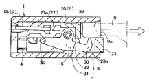
- a latch device includes a housing 1 that is open at one end, a sliding body 2 that is disposed so as to be movable forward and backward with respect to the housing 1, and an engagement body 3 that is rotatably supported by the sliding body 2. , An engaging body 3 that moves between the locking position and the unlocking position, a spring member 4 that urges the sliding body 2 in a direction to protrude from the housing 1, and a pin member 5 that traces the cam groove 27 Is a push-push locking mechanism.
- the sliding body 2 has the abutting part 22 and the cam groove 27 which contact
- the claw portion 32 of the engagement body 3 protrudes toward the abutting portion 22 side of the housing 1 to enable the striker 9 to be locked. That is, the claw portion 9a of the striker 9 is sandwiched between the abutment portion 22 and the claw portion 32 of the engaging body 3 protruding to the abutment portion side, and the striker 9 is locked. Further, when the engaging body 3 moves to the unlocking position, the claw portion 32 of the engaging body 3 retracts from the abutting portion 22 side of the housing 1 to release the striker 9.
- the sliding body 2 is pressed and moved against the urging force of the spring member 4
- the sliding body 2 is held via the cam groove 27 and the pin member 5 at the position after the movement, and The engaging body 3 moves from the locking release position to the locking position.
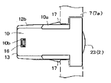
- this latch device is attached to, for example, an attachment frame 7a provided on the main body 7 side of the equipment shown in FIG.
- an attachment frame 7a provided on the main body 7 side of the equipment shown in FIG.
- a biasing member not shown
- the door 8 is pushed toward the closed position against the biasing force of a biasing member (not shown)
- the locking of the striker 9 is released.
- it is good also as a structure which attaches / detaches the to-be-latched member attached to the movable body side, such as a door, and is attached to the main body side of apparatuses.
- the housing 1, the sliding body 2, and the engaging body 3 are resin molded products, materials other than resin may be used.
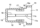
- the housing 1 has a bottomed cylindrical shape in which the inside is defined by the upper and lower walls 10, 11, the side walls 12, and the bottom wall 13, and one end is opened. ing.
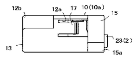
- the outer surface 15 constituting one end side of the both side walls 12 protrudes one step, and the housing 1 is inserted into the mounting frame 7a on the main body side so as to be prevented from coming off as shown in FIG. 1B.
- a pair of pin-regulating vertical ribs 14 are provided on the inner surface of the upper wall 10 at positions corresponding to both bent portions of the U-shaped pin member 5, and the U-shaped side portions 5b of the pin member 5 are formed as shown in FIG. 4A. Regulate the position.
- Each vertical rib 14 extends from the bottom wall 13 to the front side, and is provided in a state where the rear side protrudes one step larger, and restricts the position of the U-shaped side portions 5b of the pin member 5 as shown in FIG. 4A.
- the lower wall 11 has a penetrating guide groove 11a that is located in the middle in the front-rear direction and restricts the movement range of the sliding body 2, a shallow introduction groove 11b that communicates with the guide groove 11a from one end side, and protrudes on both sides of the inner surface.
- An overhanging portion 16 is provided that allows the engaging body 3 to rotate in the unlocking direction.
- the both side walls 12 are mounted with an outer surface 15 having a taper 15a with one side surface bulging and a lower corner portion notched, and a C-shaped slit 12a and projecting the tip side outward.
- Elastic claw 17 for use, and each corner of one side of the opposite wall (upper side in FIG. 3 but may be lower) of the four corners of the rectangle from the front and rear substantially intermediate portions to the front of the outer surface 15
- a taper 10a that is notched up to and a notch 12b that is provided on the rear side of the taper 10a is provided.
- Relief recesses 12c are respectively provided on the inner surfaces at one end of both side walls 12 so as to face each other.
- the relief recess 12c is a relief for a mold for forming the elastic locking claw 17 and the like.
- the bottom wall 13 is formed with a die-cutting hole 13a penetrating on both lower sides, a substantially L-shaped pin insertion hole 13b penetrating on both upper sides, and a small slit 13c between the pin insertion holes 13b.
- the elastic clamping pieces 13d and 13e, the spring support shaft 18 protruding from the inner surface, and the like are provided.
- Each pin insertion hole 13b has a hole width slightly larger than the wire diameter of the pin member 5, and allows the substantially U-shaped pin member 5 to be inserted into the case from this hole.
- the elastic clamping pieces 13d and 13e are arranged to face each other through a small gap so that the U-shaped intermediate part 5a of the pin member 5 can be held with a predetermined clamping force from the front-rear direction as shown in FIG. 1D.
- the support shaft 18 projects in the middle of the left and right.
- the pin member 5 is pivotally supported by the elastic clamping pieces 13 d and 13 e, and the spring member 4 is held by the support shaft 18.
- the spring member 4 is a coil spring, the lower side is mounted on the support shaft 18, and the upper side is locked to the protruding piece part 34 of the engaging body 3 from within a cylindrical part 26 of the sliding body 2 described later.
- the above housing 1 is devised as a mounting structure to the main body 7 side from the viewpoint of compactness as follows. That is, in the conventional structure (for example, refer to Patent Document 1), the housing is mounted on the main body side mounting frame by an insertion operation. And an elastic locking claw (same as the elastic locking claw 17). Although not shown in each of Patent Documents 1 to 3, a ridge is provided in the housing for positioning in the longitudinal direction (from the rear side to the front of the retaining frame), and the ridge is fitted into the groove on the mounting frame side. There was also a case.
- the latch device of the present invention instead of the conventional retaining frame portion, only the both side surfaces 12 and 12 of the entrance / exit side frame portion of the housing 1 bulge one step, and the outer surface 15 with the taper 15a is formed.
- the upper and lower surfaces 10 and 11 were slimmed.
- each corner portion on one side of the opposing wall among the cylindrical portions defining the housing 1 both corner portions of the upper wall 10 in this example).
- the mounting frame 7a requires a fitting hole 6 corresponding to the cross section of the housing 1, that is, a tapered corner portion 6a for positioning corresponding to the taper 10a.
- the sliding body 2 has a substantially inverted U-shaped main body 20 disposed on the entrance / exit side of the housing 1 and a rear side of the main body 20 so as to be narrower than the main body 20. And a rear extension 21.
- the main body 20 defines a substantially inverted U-shaped hollow portion 24 opened downward, and the front end surface is set as the abutting portion 22.
- the main body 20 has a frame portion 23 projecting forward from the lower portion of the front end surface, and a pivot hole shaft hole 24 a provided on the same axis with respect to both side surfaces 20 b defining the cavity portion 24.
- a through-hole 20d formed on both sides of the portion of the rear surface facing the abutting portion 22 that projects the rear extension 21.
- the cavity portion 24 of the main body 20 is partitioned on the front end side of the abutting portion 22, the upper surface 20 a, both side surfaces 20 b, and the rear extension portion 21.
- the upper surface 20a has a front rib and a rear rib so that good sliding characteristics can be obtained when the upper surface 20a is disposed in the housing 1.
- the frame part 23 forms an opening 23a through which a claw part 32 of the engagement body 3 to be described later can be projected and retracted with a margin.
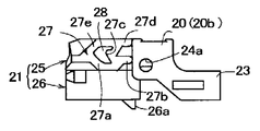
- the rear extension 21 includes an upper portion 25 having heart-shaped cam grooves 27 on both sides and a lower cylindrical portion 26 extending in the same direction as the upper portion 25.
- the cam grooves 27 on both sides have substantially the same shape as shown in FIG. 6D and are provided around the convex cam island 28.
- the cam groove 27 includes a guide groove 27a that extends from the rear side to the front lower side, a locking guide groove 27b and a release guide groove 27d that are located on the front side of the guide groove 27a and are separated into upper and lower parts, a guide groove 27b, 27d, a concave locking groove 27c located on the rear side, a return groove 27e extending rearward from the guide groove 27d, and the like.
- the cylinder portion 26 forms a cylinder hole in which the inside of the cylinder can be loosely fitted on the upper side of the support shaft 18 and the spring member 4 described above, and is a protrusion that projects from the front lower side and is fitted to the guide groove 11a. 26a, and a guide wing 29 projecting toward both sides on the rear upper side.
- the above sliding body 2 is devised as follows from the viewpoint of compactness. That is, in this structure, the sliding body 2 protrudes out of the housing at the unlocking position of the engaging body 3 to be described later with respect to the housing 1, thereby shortening the length of the housing 1.
- the sliding body 2 has a rear extension portion 21 that forms a relief portion and a cam groove 28 that are protruded rearward of the main body 20 and cut out so as to be narrower than the main body.
- the main body 20 has a cavity portion 24 provided on the rear side of the abutting portion 22 and defined by at least both side surfaces 20b, and pivot support shaft holes 24a provided on the side surfaces 20b.
- the pivot shaft hole 24a (a shaft portion may be used instead of the shaft hole 24a) is provided behind or directly below the abutting portion 22, the rear piece portion 31 of the engagement body 3 is located on the inside of the sliding body.
- the size in the width direction or the thickness direction when the engaging body 3 is pivotally supported by the sliding body 2 is shortened. As a result, the degree of freedom in designing the size and shape of the engagement body 3 is expanded, and the entire latch device can be easily made compact.
- the pin member 5 comprises a U-shaped intermediate portion 5a, both side portions 5b, and a tip 5c bent inward at the free end side of each side portion 5b as shown in FIG.
- the width dimension is formed slightly larger than the lower width dimension.
- the lower width dimension is in the housing 1 and substantially coincides with the width dimension between the inner surfaces of the side walls 21.
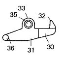
- the engaging body 3 includes a front plate portion 30 and rear piece portions 31, 31 protruding rearward from the front plate portion 30 as shown in FIGS. 3, 8 ⁇ / b> A, and 8 ⁇ / b> B.
- the front plate portion 30 has a claw portion 32 protruding upward, a protrusion portion 33 that keeps a predetermined gap with the claw portion 32 and protrudes in the same direction as the protrusion direction of the claw portion, and protrudes in the middle of the rear end surface in the left-right direction.
- a projecting piece portion 34 is provided which enters the cylinder of the cylinder portion 26 described above.
- claw part 32 is a magnitude
- the two projecting portions 33 are formed with pivot shaft portions 35 projecting on the same axis. Convex portions 36 are respectively provided on the rear outer surfaces of both rear piece portions 31.
- the above engagement body 3 is devised as follows from the viewpoint of compactness. That is, the engaging body 3 is provided with a projecting portion 33 that maintains a predetermined gap with the claw portion 32 and projects in the same direction as the projecting direction of the claw portion and forms a pivot portion shaft portion 35 (or a shaft hole). Yes.
- the engagement body 3 is pivotally supported by the fitting of the shaft portion 35 and the shaft hole 24 with respect to the sliding body side main body 20, and the engagement body 3 is movable between the locking position and the locking release position. . With the engagement body 3 positioned at the locking position, the abutting portion 22 is positioned between the claw portion 32 and the protrusion 33, and the sliding body side rear extension is performed with the engagement body 3 positioned at the locking release position.
- the latch device is configured such that the rear piece 31 of the engagement body 3 enters inside the sliding body 2, and the dimension in the width direction or the thickness direction in a state where the engagement body 3 is supported with respect to the sliding body 2. Can be easily shortened. Further, since the rotation center of the engaging body 3 (the shaft portion 35 fitted in the shaft hole 24) is set behind or directly below the abutting portion 22, the shaft portion 35 and the claw portion 32 which are pivot portions are arranged. The engagement body 3 can be made more compact by arbitrarily setting the distance between the shaft portion 35 and the projection portion 36.
- the engaging body 3 is first assembled to the sliding body 2. That is, the shaft portions 35 on both sides are pushed into the shaft hole 24a from the hollow portion of the sliding body 2 from the state of FIG. Then, the engaging body 3 is pivotally supported within a predetermined range with the shaft portion 35 as a fulcrum, and the claw portion 32 is accommodated in the opening 23a as shown in FIGS. 2B and 4C. 4A, the claw portion 32 protrudes from the opening 23a and can be moved to a locking position where the convex portion of the striker 9 or the claw 9a is sandwiched between the abutting portion 22 of the sliding body 2 and the claw portion 32 of the engaging body 3. It becomes.
- the engaging body 3 is pivotally supported on the sliding body side body 20 through the fitting of the shaft hole 24a and the shaft portion 35, and the claw portion 32 is protruded from the opening 23a to the abutting portion 22 side.
- the claw portion 32 With the abutting portion 22 positioned between the claw portion 32 and the projecting portion 33 in the state where the claw portion 32 is positioned at the stop position, the claw portion 32 retracts into the opening 23a and is positioned at the unlocking position.
- the rear piece part 31 and the convex part 36 of the engagement body 3 are released to the relief part where the extension part 21 is narrowed.
- the sliding body 2 to which the above engagement body 3 is assembled is assembled in the housing 1.
- the spring member 4 is mounted on the support shaft 18 in advance, and the pin member 5 is swingably held on the bottom wall 13 and disposed in the housing 1.
- the pin member 5 inserts the tip 5c on both sides into the housing from each pin insertion hole 13b, and then forcibly moves the U-shaped intermediate portion 5a toward the elastic clamping pieces 13d and 13e.
- the pin member 5 is sandwiched between 13e.
- the pin member 5 is held upright in the housing 1, and the position of the U-shaped side portions 5 b is regulated between the regulating vertical rib 14 and the side surface 12 of the housing 1.
- the latch device of the present invention is inserted into a mounting frame 7a provided on the equipment side main body 7 as shown in FIG. 1B, and is attached to the door 8 as shown in FIG. 4A via an elastic locking claw 17 or the like. Attached to.
- the sliding body 2 is normally biased in the protruding direction by the spring member 4 as shown in FIG. 2B, and the claw portion 32 of the engaging body 3 is similarly moved by the spring member 4 into the sliding body side opening 23a. It is urged in the direction to enter.
- the convex portion 36 elastically shifts to the lower side of the overhang portion 16, and at the same time, the claw 9 a of the striker 9 is prevented from coming off via the claw portion 32.
- the engagement body 3 has the distal ends 5c of the pin member 5 that enter the locking guide groove 27b from the guide groove 27a by the backward movement of the slide body 2 and the engagement body 3, and in the left arrow direction.
- the pressing force is released, it is locked in the locking groove 27c.
- the door 8 is held (locked) in the closed state.
- the engaging body 1030 rotates so that the claw portion 1032 retracts from the abutting portion 1022, that is, moves from the locking position to the locking release position, and is damaged. It is avoiding.
- the pulling force at that time is referred to as excessive pulling strength.
- the claw portion 1032 is provided so as to be disengaged from the shaft center 1035, that is, the rotation center line of the engagement body 1030, and receives the stress in the pulling direction of the striker 1090 Then, a rotational moment is generated with the shaft portion 1035 as a fulcrum.
- this rotational moment is proportional to the urging load or the spring load as the spring member 1040.
- the unreasonable strength decreases.
- the unreasonable strength is determined by the frictional contact between the claw portion 1032 and the inner surface of the sliding body side opening 1023a and the spring load of the spring member 1040.
- the design freedom is restricted in that respect.
- the claw portion 1032 is pressed against or frictionally contacted with the corresponding portion of the sliding body 1020 to secure the desired forcible strength against the rotational moment.
- the engagement body 3 is rotated with respect to the sliding body 2, the rotation center line when the engagement body 3 rotates with the shaft portion 35 and the shaft hole 24 a fitted or pivoted as a fulcrum, and the engagement body 3. Is engaged with the claw portion 30 of the engaging body 3 in a state in which is switched to the locking position so as to coincide with the extraction direction of the striker 9. For this reason, as shown in FIGS. 9A and 9C, when an external force is applied to open the door 8 when the door 8 is closed (the engaging body 3 is in the locked position), that is, an external force in the direction of the right arrow in FIG.
- this latch device can be expanded as follows compared to the conventional product.
- the engaging body 3 may be supported by the sliding body so that the minutes substantially coincide with the engagement / disengagement direction of the striker 9. According to this configuration, even if an unreasonable force is applied to the striker 9, this force acts on the engagement body 3 as a force directed radially outward from the center of rotation, and no rotational moment is generated in the engagement body 3.
- FIG. 9C shows a configuration in which the contact surface of the claw portion 32 with respect to the striker 9 is inclined by a minute angle x.
- the claw portion is pressed against the corresponding portion of the sliding body (the inner surface of the frame portion that defines the opening) or frictionally contacted as in the past in order to ensure unreasonable strength. Since it becomes unnecessary, stable operation can be maintained even at low temperatures, and the problem of sliding noise caused by pressure contact and friction can be easily solved. Further, the unreasonable strength of the latch device can be freely set without being restricted by the frictional contact between the conventional claw portion and the inner surface of the sliding body side opening and the spring load of the spring member 4.
- the claw portion 32 of the engagement body 3 does not frictionally contact the inner surface of the sliding body side opening 23a. This is because a gap is set between the opening 23a and the claw portion 32 as shown in FIG. 9C. Therefore, in the latch device of the present invention, the unreasonable strength can be set by the contact shape between the claw portion 32 of the engaging body 3 and the claw 9 a of the striker 9. Therefore, since the unreasonable strength is hardly influenced by the spring load of the spring member 4, the latch operating force can be arbitrarily set, and the degree of freedom in design can be improved.
- the present invention can be variously modified without being limited to the above-described form.
- the structure in which the engaging body 3 is pivotally supported by the sliding body 2 is provided with a shaft portion instead of the shaft hole 24a, and the engaging body 3 is provided with a shaft hole instead of the shaft portion 35. Then, the engaging body 3 is pivotally supported with respect to the sliding body 2 through the fitting of the shaft portion and the shaft hole, and both the sliding body 2 and the engaging body 3 are provided with shaft holes.
- a configuration may be adopted in which the sliding body 2 is pivotally supported via a shaft inserted through the shaft holes.
- a more compact latch device can be provided while maintaining the locking force and rigidity of the engaging body as much as possible, and the application of the latch device can be expanded.
Abstract
Description
係合体1030は、摺動体1020の軸穴部に対応して係合体1030の両側に設けられた軸部1035に嵌合された状態で枢支される。この構造により、摺動体1020の位置移動により、図8Bのごとく爪部1032を突当部1022側に突出させてストライカー1090を係止する係止位置と、図8Aのごとく爪部1032を突当部1022側から退行させた係止解除位置との間を移動する。
係止解除位置では、摺動体1020がばね部材1040の付勢力でハウジング1010の入口側に移動され、係合体1030がハウジング1010内に設けられた張出部1016に凸部1036を乗り上げることでその状態を保つ。
係止位置では、ストライカー1090に加えられた押し力でばね部材1040の付勢力に抗して摺動体1020がハウジング1010の奥側に移動され、該移動後の位置にカム溝1027及びピン部材1050の係合を介し保持され、係合体1030の凸部1036が張出部1016の裾の低い部分に移動し、かつ係合体1030が傾動して爪部1032を摺動体側の開口1023a内から突出させる。 8A and 8B show a push-type latch device disclosed in
The
In the unlocking position, the sliding
In the locking position, the
本体側にラッチ装置を取り付け、扉側にストライカー1090を設けた場合では、図8Bが扉を本体に保持(ロック)した状態を示し、扉側のストライカー1090が本体側のラッチ装置を構成している係合体1030により係止される。この係止は、扉が再び本体側へ押されることで、ピン部材1050がカム溝1027の係止溝から外れて図8Aのごとく係止解除される。このような構造は特許文献2や特許文献3のラッチ装置でも同様である。 In other words, in the above latch device, the
When the latch device is attached to the main body side and the
(1) ハウジングと、
被係脱部材と当接する突当部及びカム溝を有して前記ハウジングに対し進退可能に配置された摺動体と、
前記摺動体を前記ハウジングから突出する方向へ付勢するばね部材と、
前記摺動体に対し回転自在に支持されて、その先端に爪部を有する係合体と、
前記カム溝をトレースするように動くピン部材とを備え、
前記係合体は、前記爪部を前記突当部側に突出させて前記被係脱部材を係止する係止位置及び、前記爪部が前記突当部側から退行した係止解除位置との間を移動可能であり、
前記摺動体が押圧されて前記ばね部材の付勢力に抗して前記摺動体が移動すると、前記摺動体はその移動後の位置に前記カム溝及びピン部材を介して保持され、かつ前記係合体が前記係止解除位置から前記係止位置に移動し、
前記係合体は、前記爪部の突出方向と同じ方向に突出する突出部を有し、
前記係合体を前記摺動体に回転自在に支持する枢支部が前記突出部に設けられ、
前記係合体が前記係止位置に位置した状態で、前記爪部と前記突出部との間に前記摺動体の前記突当部が位置するラッチ装置。
(2) ハウジングと、
被係脱部材と当接する突当部及びカム溝を有して前記ハウジングに対し進退可能に配置された摺動体と、
前記摺動体を前記ハウジングから突出する方向へ付勢するばね部材と、
前記摺動体に対し回転自在に支持されて、その先端に爪部を有する係合体と、
前記カム溝をトレースするように動くピン部材とを備え、
前記係合体は、前記爪部を前記突当部側に突出させて前記被係脱部材を係止する係止位置及び、前記爪部が前記突当部側から退行した係止解除位置との間を移動可能であり、
前記摺動体が押圧されて前記ばね部材の付勢力に抗して前記摺動体が移動すると、前記摺動体はその移動後の位置に前記カム溝及びピン部材を介して保持され、かつ前記係合体が前記係止解除位置から前記係止位置に移動し、
前記摺動体の前記突当部は、前記ハウジングの出入口側に配置され、
前記摺動体の前記カム溝は、前記ハウジングの奥側に配置され、
前記摺動体は、前記突当部と前記カム溝との間に前記係合体を回転自在に支持する枢支部を有するラッチ装置。
なお、上記突当部側とは、図4Aのごとくラッチ装置を横配置にした場合、図4Aのごとく爪部を突当部に近づけように突出させる態様を含む。
(3) (1)または(2)のラッチ装置において、
前記摺動体は、
略逆U字状の本体と、
前記本体の後方に突出され、前記本体よりも幅の狭い幅細部位を有する後延長部とを有し、
前記カム溝は前記幅細部位に形成されており、
前記突当部は前記本体の逆U字状の前端面であり、
前記本体の両側面に前記枢支部用軸穴又は軸部が設けられ、
前記係合体は、
前記爪部を設けた前板部と、
前記前板部から後方へ突設した後片部と、
前記後片部の側面に設けられた凸部とを有し、
前記凸部が、前記後延長部の幅細部へ移行しながら前記ハウジング内に設けられた張出部に乗り上げることで、前記係合体は前記係止位置から係止解除位置に移動する。
(4) (1)または(2)のラッチ装置において、
前記係合体の回転中心である前記枢支部と、前記係合体が前記係止位置に位置する状態での前記爪部とを結ぶ線分が前記被係脱部材の係脱方向と略一致するように、前記係合体が前記摺動体に支持される。
(5) (4)のラッチ装置において、
前記係合体は、前板部と、前記前板部から後方へ突設した後片部とを有し、
前記前板部は、前記爪部と、前記爪部と所定隙間を保ちかつ該爪部と同方向に突設され枢支部用軸部又は軸穴を備える突出部を有し、
前記後片部は、その側面に設けられた凸部を有し、
前記凸部が前記ハウジングの内側に設けられた張出部に乗り上げることで、前記係合体を前記係止位置から前記係止解除位置に移動させる。 In order to achieve the above object, according to the present invention, the following latch device is provided.
(1) a housing;
A sliding body that has an abutting portion that comes into contact with the engaged / disengaged member and a cam groove, and is arranged to be able to advance and retreat with respect to the housing;
A spring member for biasing the sliding body in a direction protruding from the housing;
An engagement body that is rotatably supported with respect to the sliding body and has a claw at its tip;
A pin member that moves so as to trace the cam groove,
The engaging body includes: a locking position where the claw portion protrudes toward the abutting portion to lock the engaged member; and an unlocking position where the claw portion retracts from the abutting portion side. Can move between,
When the sliding body is pressed and moves against the urging force of the spring member, the sliding body is held in the position after the movement via the cam groove and the pin member, and the engaging body. Moves from the unlocking position to the locking position,
The engaging body has a protruding portion that protrudes in the same direction as the protruding direction of the claw portion,
A pivotal support for rotatably supporting the engaging body on the sliding body is provided on the protrusion.
A latch device in which the abutting portion of the sliding body is positioned between the claw portion and the protruding portion in a state where the engaging body is located at the locking position.
(2) a housing;
A sliding body that has an abutting portion that comes into contact with the engaged / disengaged member and a cam groove, and is arranged to be able to advance and retreat with respect to the housing;
A spring member for biasing the sliding body in a direction protruding from the housing;
An engagement body that is rotatably supported with respect to the sliding body and has a claw at its tip;
A pin member that moves so as to trace the cam groove,
The engaging body includes: a locking position where the claw portion protrudes toward the abutting portion to lock the engaged member; and an unlocking position where the claw portion retracts from the abutting portion side. Can move between,
When the sliding body is pressed and moves against the urging force of the spring member, the sliding body is held in the position after the movement via the cam groove and the pin member, and the engaging body. Moves from the unlocking position to the locking position,
The abutting portion of the sliding body is disposed on the entrance / exit side of the housing,
The cam groove of the sliding body is disposed on the back side of the housing,
The said sliding body is a latch apparatus which has a pivot part which supports the said engaging body rotatably between the said abutting part and the said cam groove.
In addition, the said abutting part side includes the aspect which makes a nail | claw part protrude so that it may approach the abutting part like FIG. 4A, when a latch apparatus is laterally arranged like FIG. 4A.
(3) In the latch device of (1) or (2),
The sliding body is
A substantially inverted U-shaped body;
A rear extension projecting rearward of the main body and having a narrow portion narrower than the main body,
The cam groove is formed in the narrow portion,
The abutting portion is an inverted U-shaped front end surface of the main body,
The pivot support shaft hole or the shaft portion is provided on both side surfaces of the main body,
The engaging body is
A front plate portion provided with the claw portion;
A rear piece projecting rearward from the front plate, and
A convex portion provided on a side surface of the rear piece,
The engaging body moves from the locking position to the locking release position by climbing over the overhanging portion provided in the housing while shifting to the width detail of the rear extension.
(4) In the latch device of (1) or (2),
A line segment that connects the pivot portion that is the rotation center of the engaging body and the claw portion in a state in which the engaging body is located at the locking position substantially matches the engagement / disengagement direction of the engaged / disengaged member. Further, the engaging body is supported by the sliding body.
(5) In the latch device of (4),
The engaging body has a front plate portion and a rear piece portion protruding rearward from the front plate portion,
The front plate portion includes the claw portion, and a protrusion having a predetermined gap with the claw portion and projecting in the same direction as the claw portion and having a pivot portion shaft portion or a shaft hole.
The rear piece portion has a convex portion provided on a side surface thereof,
The convex portion rides on a protruding portion provided inside the housing, thereby moving the engaging body from the locking position to the locking release position.
このため、本発明のラッチ装置によれば、係合体の後片部を摺動体の内側により入り込むようにして、摺動体に対し係合体を支持した状態、つまり係合体と組み合わされた摺動体の幅方向ないしは厚さ方向の寸法、引いてはハウジングの厚さを短縮できる。
なお、実施の形態に詳述するように、係合体が係止解除位置に位置した状態で摺動体がハウジングから外へ突出するように構成するとハウジングの長さを短縮できる。また、係合体の枢支部が突当部の後方ないしは真下に配置されるので、例えば、係合体の枢支部から爪部、枢支部から凸部までのそれぞれの距離等を自由に設計でき、ひいては係合体の形状の設計自由度を拡大できる。以上の要因等によりラッチ装置のコンパクト化が可能となる。 According to the latch device according to the embodiment of the present invention, the engaging body has the claw portion and the pivot portion protruding portion provided at predetermined intervals as shown in FIGS. 4A to 4D, and is arranged at the locking position. In this state, the engaging body is supported with respect to the sliding body such that the abutting portion of the sliding body is positioned between the claw portion and the protruding portion.
For this reason, according to the latch device of the present invention, the rear piece of the engaging body is inserted into the inside of the sliding body so that the engaging body is supported with respect to the sliding body, that is, the sliding body combined with the engaging body. The dimension in the width direction or the thickness direction, that is, the thickness of the housing can be shortened.
As described in detail in the embodiment, the length of the housing can be shortened by configuring the sliding body to protrude outward from the housing in a state where the engaging body is located at the unlocking position. In addition, since the pivot part of the engaging body is arranged behind or directly below the abutment part, for example, the distance from the pivot part of the engaging body to the claw part, the distance from the pivot part to the convex part, etc. can be freely designed, and thus The degree of freedom in designing the shape of the engagement body can be expanded. Due to the above factors, the latch device can be made compact.
本発明の実施形態にかかるラッチ装置は、一端側を開口したハウジング1と、ハウジング1に対し進退可能に配置された摺動体2と、摺動体2に対し回転自在に支持される係合体3と、係止位置及び係止解除位置の間を移動する係合体3と、摺動体2をハウジング1から突出する方向へ付勢しているばね部材4と、カム溝27をトレースするピン部材5とを備えるプッシュ・プッシュ係止機構である。
ここで、摺動体2は被係脱部材としてのストライカー9と当接する突当部22及びカム溝27を有する。係合体3が係止位置に移動すると、係合体3の爪部32がハウジング1の突当部22側に突出してストライカー9を係止可能にする。つまり、突当部22とこの突当部側に突出された係合体3の爪部32とでストライカー9の爪部9aを挟持し、ストライカー9が係止される。また、係合体3が係止解除位置に移動すると、係合体3の爪部32がハウジング1の突当部22側から退行し、ストライカー9の係止を解除する。
この構造によって、摺動体2が押圧されてばね部材4の付勢力に抗して移動されると、その移動後の位置に摺動体2がカム溝27及びピン部材5を介して保持され、かつ係合体3が係止解除位置から係止位置に移動する。 (Device structure)
A latch device according to an embodiment of the present invention includes a
Here, the sliding
With this structure, when the sliding
上壁10の内面には、一対のピン規制用縦リブ14がU字型のピン部材5の両屈曲部に対応する位置に設けられ、図4Aのごとくピン部材5のU形両側部5bの位置を規制する。各縦リブ14は、底壁13から前側に延び、かつ、後側が一段大きく張り出した状態に設けられて、図4Aのごとくピン部材5のU形両側部5bを位置規制する。
下壁11には、前後方向の中間に位置して摺動体2の移動範囲を規制する貫通ガイド溝11aと、一端側からガイド溝11aに連通している浅い導入溝11bと、内面両側に突設されて係合体3を係止解除方向へ回転可能にする張出部16とが設けられている。
両側壁12には、出入口側枠部のうち両側面を一段膨出しかつ下角部を切り欠いたテーパー15a付きの外面15と、C形スリット12aで区画されて先端側を外へ張り出している取付用の弾性係止爪17と、矩形の4箇所の角部のうち対向壁の一方側(図3では上側であるが下側でもよい)の各角部を前後略中間部から外面15の手前まで切り欠いたテーパー10aと、テーパー10aより後側に設けられた切欠部12bとが設けられている。
両側壁12の一端側内面には、逃げ凹部12cがそれぞれ対向して設けられている。逃げ凹部12cは、弾性係止爪17などを形成するための成形型用の逃げである。 Here, as shown in FIGS. 3 and 5A to 5D, the
A pair of pin-regulating
The
The both
Relief recesses 12c are respectively provided on the inner surfaces at one end of both
これに対して本発明のラッチ装置では、従来の抜止用枠部に代えてハウジング1の出入口側枠部のうち両側面12,12だけを一段膨出し、かつテーパー15a付きの外面15にすることで上下面10,11のスリム化を図った。また、従来の外面に長手方向に設けられる位置決め用凸条に代えて、ハウジング1を区画している筒部のうち対向壁の一方側の各角部(この例では上壁10の両角部)を外面15の手前まで切り欠いた位置決め用テーパー10aに形成することで外周のスリム化を図った。勿論、この構造では、取付枠7aがハウジング1の断面と対応した嵌合穴6、つまりテーパー10aに対応する位置出し用のテーパー状角部6aを必須としている。 By the way, the
On the other hand, in the latch device of the present invention, instead of the conventional retaining frame portion, only the both side surfaces 12 and 12 of the entrance / exit side frame portion of the
両側のカム溝27は、図6Dのごとく互いに略同様の形状であり、凸状カム島28の周りに設けられる。カム溝27は、後側から前下側へ延びる誘導溝27aと、誘導溝27aの前側に位置して上下に別れている係止用誘導溝27b及び解除用誘導溝27dと、誘導溝27b,27dの間でかつ後側に位置した凹状係止溝27cと、誘導溝27dから後側へ延びる復帰溝27eなどで構成されている。
筒部26は、筒内が上記した支持軸18及びばね部材4の上側を遊嵌可能な筒孔を形成しており、前下側に突設されて上記ガイド溝11aと嵌合される突起26aと、後上側で両側に向けて突設されているガイド用小翼29とを有している。 The
The
The
このため、係合体3の後片部31が摺動体2の内側により入り込むようにラッチ装置を構成して、摺動体2に対し係合体3を支持した状態での幅方向ないしは厚さ方向の寸法を容易に短縮できる。また、係合体3の回転中心(軸穴24に嵌合している軸部35)を突当部22の後方ないしは真下に設定しているので、枢支部である軸部35と爪部32の間の距離、軸部35と凸部36の間の距離などを任意に設定することで、係合体3をよりコンパクト化できる。 By the way, the
Therefore, the latch device is configured such that the
以上の各部材は、例えば、係合体3がまず摺動体2に組み付けられる。すなわち、図3の状態から両側の軸部35を摺動体2の空洞部内から軸穴24aに押し込む。
すると、係合体3は、軸部35を支点として、所定範囲内を回転自在に枢支され、図2B及び図4Cのごとく爪部32が開口23a内に収まった係止解除位置と、図2A及び図4Aのごとく爪部32が開口23aから突出されてストライカー9の凸部又は爪9aを摺動体2の突当部22と係合体3の爪部32とで挟む係止位置とに移動可能となる。また、この係合体3は、摺動体側本体20に対し軸穴24aと軸部35の嵌合を介して枢支されて、爪部32が開口23aから突当部22側に突出された係止位置に位置された状態で、爪部32と突出部33との間に突当部22を位置させ、爪部32が開口23a内に退行して係止解除位置に配置された状態で後延長部21の細くなった逃げ部に係合体3の後片部31及び凸部36を逃がす。 (Assembly method)
In each of the above members, for example, the engaging
Then, the engaging
ピン部材5は、両側の先端5cを各ピン挿通穴13bからハウジング内に挿入してから、U形中間部5aを弾性挟持片13d,13e側に強制的に移動させ、その両挟持片13d,13eの間にピン部材5を挟持する。この挟持状態では、ピン部材5がハウジング1内に起立保持され、U形両側部5bの位置が規制用縦リブ14とハウジング1の側面12との間に規制される。また、係合体3が組み付けられた摺動体2がハウジング1内に押し込まれると、摺動体2の突起26aが導入溝11bからガイド溝11aに落ち込んで嵌合され、摺動体2がハウジング1に対し抜け止めされて組み付けられる。この押し込み過程では、ばね部材4の上側が筒部26内に入り、係合体3の突片部34に当接する。そして、ばね部材4は、摺動体2が奥へ押圧移動される過程で付勢力を増大し、該付勢力によって係合体3を軸部35を支点として係止位置方向へ回転可能にする。また、ピン部材5の両先端5cは、対応するカム溝27の溝入口に入る。 Next, the sliding
The
以上の組立方法によって完成された本発明のラッチ装置の使用態様を説明する。
例えば、本発明のラッチ装置は、図1Bのごとく機器類側本体7に設けられた取付枠7aに挿入され、弾性係止爪17等を介して図4Aのごとく扉8に取り付けられたストライカー9に取り付けられる。本発明のラッチ装置は取付状態において、通常、図2Bのごとく摺動体2はばね部材4により突出方向へ付勢され、同じくばね部材4により係合体3の爪部32が摺動体側開口23a内に入る方向へ付勢される。なお、摺動体2の移動は突起26aがガイド溝11aの前端面に当たることで規制され、爪部32の回転は凸部36が張出部16の最も高くなった箇所に乗り上げて規制される。この状態が「係合体3の係止解除位置」である。
そして、扉8が閉方向である図4Aの左矢印方向に押されると、摺動体2はストライカー9によりばね部材4の付勢力に抗してハウジング内に没する方向へ押圧移動される。その移動過程では係合体3が軸部35を支点として係止位置方向へ回転される。すると、係合体3は、凸部36が張出部16の低い側へ弾性的に移行し、同時にストライカー9の爪9aを爪部32を介して抜け止めする。このとき、係合体3は、図4Aのごとくピン部材5の各先端5cが摺動体2及び係合体3の後方移動によって上記した誘導溝27aから係止用誘導溝27bに入り、左矢印方向の押圧力を解放したときに、係止溝27cに係止される。この係止により、扉8が閉状態に保持(ロック)される。 (Operation)
A use mode of the latch device of the present invention completed by the above assembling method will be described.
For example, the latch device of the present invention is inserted into a mounting
When the
また、従来構造では、上述したごとく爪部1032を摺動体1020の対応部に圧接したり摩擦接触させることで前記回転モーメントに抗して目的の無理抜き強度を確保する。この爪部1032が摺動体1020の対応部に摩擦接触する構造では、例えば、使用環境が低温になると、部材間が凍結して圧接抵抗や摩擦抵抗が大きくなって係合体の回転が妨げられて作動不良の要因となる。しかも、無理抜き強度がばらついたり圧接や摩擦に起因した摺動音が発生し易くなったりする。なお、特許文献3の技術は、そのような作動不良を解消したものであるが、微細加工を必須としているため小型化すると実施が困難となる。 However, this rotational moment is proportional to the urging load or the spring load as the
In the conventional structure, as described above, the claw portion 1032 is pressed against or frictionally contacted with the corresponding portion of the sliding
これとは反対に、無理抜きが可能なラッチ装置を構成する場合は、ストライカー9の爪9aの当接面と、係合体3の爪部32の当接面とが微少角度をもって当接するように設計すればよい。図9Cはその一例として、ストライカー9に対する爪部32の当接面を微小角xだけ傾斜した構成を示している。
この構成によれば、ストライカー9に無理抜きの力Fがかけられると、爪部32の当接面がストライカー9に対して微少角xだけ傾いているので、F・sinxの力が係合体3の爪部32に図9Cの下向きに加わる。この力F・sinxがストライカー9と爪部32との間の摩擦抵抗よりも大きくなると、爪部32はストライカー9の上を滑り、係合体3が係止解除位置に向かって回転する。したがって、角度xを適切に選択すればラッチ装置の無理抜き強度を自在に設定することができる。
このようにして、本発明のラッチ装置においては、無理抜き強度を確保するため従来のごとく爪部を摺動体の対応部(開口を区画している枠部の内面)に圧接したり摩擦接触する必要がなくなるため、低温時においても安定した作動を維持でき、圧接や摩擦に起因した摺動音の問題を簡易に解消できる。また、従来の爪部と摺動体側開口の内面との間の摩擦接触とばね部材4のスプリング荷重とに制約されず、自在にラッチ装置の無理抜き強度を設定することができる。 For example, when configuring a latch device that cannot be forcibly removed, a line connecting the
On the other hand, when configuring a latch device that can be forcibly removed, the contact surface of the
According to this configuration, when an unreasonable force F is applied to the
In this way, in the latch device of the present invention, the claw portion is pressed against the corresponding portion of the sliding body (the inner surface of the frame portion that defines the opening) or frictionally contacted as in the past in order to ensure unreasonable strength. Since it becomes unnecessary, stable operation can be maintained even at low temperatures, and the problem of sliding noise caused by pressure contact and friction can be easily solved. Further, the unreasonable strength of the latch device can be freely set without being restricted by the frictional contact between the conventional claw portion and the inner surface of the sliding body side opening and the spring load of the
本出願は、2008年10月29日出願の日本特許出願(特願2008-277545)、2008年10月29日出願の日本特許出願(特願2008-277549)に基づくものであり、その内容はここに参照として取り込まれる。 Although the present invention has been described in detail and with reference to specific embodiments, it will be apparent to those skilled in the art that various changes and modifications can be made without departing from the spirit and scope of the invention.
This application is based on a Japanese patent application filed on October 29, 2008 (Japanese Patent Application No. 2008-277545) and a Japanese patent application filed on October 29, 2008 (Japanese Patent Application No. 2008-277549). Incorporated herein by reference.
16…張出部
18…支持軸
2…摺動体
20…本体
21…後延長部
22…突当部
24a…軸穴
27…カム溝
27c…係止溝
3…係合体
30…前板部
31…後片部
32…爪部
33…突出部
35…軸部
4…ばね部材
5…ピン部材
7…機器類の本体
8…扉
9…被係脱部材としてのストライカー DESCRIPTION OF
Claims (8)
- ハウジングと、
被係脱部材と当接する突当部及びカム溝を有して前記ハウジングに対し進退可能に配置された摺動体と、
前記摺動体を前記ハウジングから突出する方向へ付勢するばね部材と、
前記摺動体に対し回転自在に支持されて、その先端に爪部を有する係合体と、
前記カム溝をトレースするように動くピン部材とを備え、
前記係合体は、前記爪部を前記突当部側に突出させて前記被係脱部材を係止する係止位置及び、前記爪部が前記突当部側から退行した係止解除位置との間を移動可能であり、
前記摺動体が押圧されて前記ばね部材の付勢力に抗して前記摺動体が移動すると、前記摺動体はその移動後の位置に前記カム溝及びピン部材を介して保持され、かつ前記係合体が前記係止解除位置から前記係止位置に移動し、
前記係合体は、前記爪部の突出方向と同じ方向に突出する突出部を有し、
前記係合体を前記摺動体に回転自在に支持する枢支部が前記突出部に設けられ、
前記係合体が前記係止位置に位置した状態で、前記爪部と前記突出部との間に前記摺動体の前記突当部が位置するラッチ装置。 A housing;
A sliding body that has an abutting portion that comes into contact with the engaged / disengaged member and a cam groove, and is arranged to be able to advance and retreat with respect to the housing;
A spring member for biasing the sliding body in a direction protruding from the housing;
An engagement body that is rotatably supported with respect to the sliding body and has a claw at its tip;
A pin member that moves so as to trace the cam groove,
The engaging body includes: a locking position where the claw portion protrudes toward the abutting portion to lock the engaged member; and an unlocking position where the claw portion retracts from the abutting portion side. Can move between,
When the sliding body is pressed and moves against the urging force of the spring member, the sliding body is held in the position after the movement via the cam groove and the pin member, and the engaging body. Moves from the unlocking position to the locking position,
The engaging body has a protruding portion that protrudes in the same direction as the protruding direction of the claw portion,
A pivotal support for rotatably supporting the engaging body on the sliding body is provided on the protrusion.
A latch device in which the abutting portion of the sliding body is positioned between the claw portion and the protruding portion in a state where the engaging body is located at the locking position. - ハウジングと、
被係脱部材と当接する突当部及びカム溝を有して前記ハウジングに対し進退可能に配置された摺動体と、
前記摺動体を前記ハウジングから突出する方向へ付勢するばね部材と、
前記摺動体に対し回転自在に支持されて、その先端に爪部を有する係合体と、
前記カム溝をトレースするように動くピン部材とを備え、
前記係合体は、前記爪部を前記突当部側に突出させて前記被係脱部材を係止する係止位置及び、前記爪部が前記突当部側から退行した係止解除位置との間を移動可能であり、
前記摺動体が押圧されて前記ばね部材の付勢力に抗して前記摺動体が移動すると、前記摺動体はその移動後の位置に前記カム溝及びピン部材を介して保持され、かつ前記係合体が前記係止解除位置から前記係止位置に移動し、
前記摺動体の前記突当部は、前記ハウジングの出入口側に配置され、
前記摺動体の前記カム溝は、前記ハウジングの奥側に配置され、
前記摺動体は、前記突当部と前記カム溝との間に前記係合体を回転自在に支持する枢支部を有するラッチ装置。 A housing;
A sliding body that has an abutting portion that comes into contact with the engaged / disengaged member and a cam groove, and is arranged to be able to advance and retreat with respect to the housing;
A spring member for biasing the sliding body in a direction protruding from the housing;
An engagement body that is rotatably supported with respect to the sliding body and has a claw at its tip;
A pin member that moves so as to trace the cam groove,
The engaging body includes: a locking position where the claw portion protrudes toward the abutting portion to lock the engaged member; and an unlocking position where the claw portion retracts from the abutting portion side. Can move between,
When the sliding body is pressed and moves against the urging force of the spring member, the sliding body is held in the position after the movement via the cam groove and the pin member, and the engaging body. Moves from the unlocking position to the locking position,
The abutting portion of the sliding body is disposed on the entrance / exit side of the housing,
The cam groove of the sliding body is disposed on the back side of the housing,
The said sliding body is a latch apparatus which has a pivot part which supports the said engaging body rotatably between the said abutting part and the said cam groove. - 請求項1に記載のラッチ装置において、
前記摺動体は、
略逆U字状の本体と、
前記本体の後方に突出され、前記本体よりも幅の狭い幅細部位を有する後延長部とを有し、
前記カム溝は前記幅細部位に形成されており、
前記突当部は前記本体の逆U字状の前端面であり、
前記本体の両側面に前記枢支部用軸穴又は軸部が設けられ、
前記係合体は、
前記爪部を設けた前板部と、
前記前板部から後方へ突設した後片部と、
前記後片部の側面に設けられた凸部とを有し、
前記凸部が、前記後延長部の幅細部へ移行しながら前記ハウジング内に設けられた張出部に乗り上げることで、前記係合体は前記係止位置から係止解除位置に移動する。 The latch device according to claim 1, wherein
The sliding body is
A substantially inverted U-shaped body;
A rear extension projecting rearward of the main body and having a narrow portion narrower than the main body,
The cam groove is formed in the narrow portion,
The abutting portion is an inverted U-shaped front end surface of the main body,
The pivot support shaft hole or the shaft portion is provided on both side surfaces of the main body,
The engaging body is
A front plate portion provided with the claw portion;
A rear piece projecting rearward from the front plate, and
A convex portion provided on a side surface of the rear piece,
The engaging body moves from the locking position to the locking release position by climbing on the overhanging portion provided in the housing while shifting to the width detail of the rear extension. - 請求項2に記載のラッチ装置において、
前記摺動体は、
略逆U字状の本体と、
前記本体の後方に突出され、前記本体よりも幅の狭い幅細部位を有する後延長部とを有し、
前記カム溝は前記幅細部位に形成されており、
前記突当部は前記本体の逆U字状の前端面であり、
前記本体の両側面に前記枢支部用軸穴又は軸部が設けられ、
前記係合体は、
前記爪部を設けた前板部と、
前記前板部から後方へ突設した後片部と、
前記後片部の側面に設けられた凸部とを有し、
前記凸部が、前記後延長部の幅細部へ移行しながら前記ハウジング内に設けられた張出部に乗り上げることで、前記係合体は前記係止位置から係止解除位置に移動する。 The latch device according to claim 2,
The sliding body is
A substantially inverted U-shaped body;
A rear extension projecting rearward of the main body and having a narrow portion narrower than the main body,
The cam groove is formed in the narrow portion,
The abutting portion is an inverted U-shaped front end surface of the main body,
The pivot support shaft hole or the shaft portion is provided on both side surfaces of the main body,
The engaging body is
A front plate portion provided with the claw portion;
A rear piece projecting rearward from the front plate, and
A convex portion provided on a side surface of the rear piece,
The engaging body moves from the locking position to the locking release position by climbing on the overhanging portion provided in the housing while shifting to the width detail of the rear extension. - 請求項1に記載のラッチ装置において、
前記係合体の回転中心である前記枢支部と、前記係合体が前記係止位置に位置する状態での前記爪部とを結ぶ線分が前記被係脱部材の係脱方向と略一致するように、前記係合体が前記摺動体に支持される。 The latch device according to claim 1, wherein
A line segment that connects the pivot portion that is the rotation center of the engaging body and the claw portion in a state in which the engaging body is located at the locking position substantially matches the engagement / disengagement direction of the engaged member. Further, the engaging body is supported by the sliding body. - 請求項2に記載のラッチ装置において、
前記係合体の回転中心である前記枢支部と、前記係合体が前記係止位置に位置する状態での前記爪部とを結ぶ線分が前記被係脱部材の係脱方向と略一致するように、前記係合体が前記摺動体に支持される。 The latch device according to claim 2,
A line segment that connects the pivot portion that is the rotation center of the engaging body and the claw portion in a state in which the engaging body is located at the locking position substantially matches the engagement / disengagement direction of the engaged member. Further, the engaging body is supported by the sliding body. - 請求項5に記載のラッチ装置において、
前記係合体は、前板部と、前記前板部から後方へ突設した後片部とを有し、
前記前板部は、前記爪部と、前記爪部と所定隙間を保ちかつ該爪部と同方向に突設され枢支部用軸部又は軸穴を備える突出部を有し、
前記後片部は、その側面に設けられた凸部を有し、
前記凸部が前記ハウジングの内側に設けられた張出部に乗り上げることで、前記係合体を前記係止位置から前記係止解除位置に移動させる。 The latch device according to claim 5, wherein
The engaging body has a front plate portion and a rear piece portion protruding rearward from the front plate portion,
The front plate portion includes the claw portion, and a projection portion that maintains a predetermined gap with the claw portion and projects in the same direction as the claw portion and includes a pivot portion shaft portion or a shaft hole.
The rear piece portion has a convex portion provided on a side surface thereof,
The convex portion rides on a protruding portion provided inside the housing, thereby moving the engaging body from the locking position to the locking release position. - 請求項6に記載のラッチ装置において、
前記係合体は、前板部と、前記前板部から後方へ突設した後片部とを有し、
前記前板部は、前記爪部と、前記爪部と所定隙間を保ちかつ該爪部と同方向に突設され枢支部用軸部又は軸穴を備える突出部を有し、
前記後片部は、その側面に設けられた凸部を有し、
前記凸部が前記ハウジングの内側に設けられた張出部に乗り上げることで、前記係合体を前記係止位置から前記係止解除位置に移動させる。 The latch device according to claim 6, wherein
The engaging body has a front plate portion and a rear piece portion protruding rearward from the front plate portion,
The front plate portion includes the claw portion, and a projection portion that maintains a predetermined gap with the claw portion and projects in the same direction as the claw portion and includes a pivot portion shaft portion or a shaft hole.
The rear piece portion has a convex portion provided on a side surface thereof,
The convex portion rides on a protruding portion provided inside the housing, thereby moving the engaging body from the locking position to the locking release position.
Priority Applications (4)
| Application Number | Priority Date | Filing Date | Title |
|---|---|---|---|
| CN200980143214.1A CN102197185B (en) | 2008-10-29 | 2009-10-29 | Latch device |
| ES09823670.6T ES2636013T3 (en) | 2008-10-29 | 2009-10-29 | Bolt device |
| US12/998,519 US8973956B2 (en) | 2008-10-29 | 2009-10-29 | Latch device |
| EP09823670.6A EP2343426B1 (en) | 2008-10-29 | 2009-10-29 | Latch device |
Applications Claiming Priority (4)
| Application Number | Priority Date | Filing Date | Title |
|---|---|---|---|
| JP2008-277545 | 2008-10-29 | ||
| JP2008-277549 | 2008-10-29 | ||
| JP2008277549A JP5171547B2 (en) | 2008-10-29 | 2008-10-29 | Latch device |
| JP2008277545A JP5171546B2 (en) | 2008-10-29 | 2008-10-29 | Latch device |
Publications (1)
| Publication Number | Publication Date |
|---|---|
| WO2010050560A1 true WO2010050560A1 (en) | 2010-05-06 |
Family
ID=42128919
Family Applications (1)
| Application Number | Title | Priority Date | Filing Date |
|---|---|---|---|
| PCT/JP2009/068607 WO2010050560A1 (en) | 2008-10-29 | 2009-10-29 | Latch device |
Country Status (5)
| Country | Link |
|---|---|
| US (1) | US8973956B2 (en) |
| EP (1) | EP2343426B1 (en) |
| CN (1) | CN102197185B (en) |
| ES (1) | ES2636013T3 (en) |
| WO (1) | WO2010050560A1 (en) |
Cited By (2)
| Publication number | Priority date | Publication date | Assignee | Title |
|---|---|---|---|---|
| CN103797203A (en) * | 2011-07-13 | 2014-05-14 | 株式会社利富高 | Latch device |
| CN109790729A (en) * | 2016-12-19 | 2019-05-21 | 宝马股份公司 | The closure bow of motor vehicle body lock, the motor vehicle body lock with this closure bow and the motor vehicle being correspondingly equipped with |
Families Citing this family (10)
| Publication number | Priority date | Publication date | Assignee | Title |
|---|---|---|---|---|
| KR101825925B1 (en) | 2011-10-18 | 2018-02-06 | 삼성에스디아이 주식회사 | Locking apparatus device for case and case having the same |
| CA2880398C (en) * | 2012-07-30 | 2017-07-18 | Rutherford Controls Int'l Inc. | Electric strike assembly |
| WO2014099225A1 (en) * | 2012-12-19 | 2014-06-26 | Illinois Tool Works Inc. | Whistle assembly |
| EP3033464B1 (en) * | 2013-08-14 | 2019-01-02 | Dr. Schneider Kunststoffwerke GmbH | Device with push-push mechanism |
| EP2995755B1 (en) * | 2014-09-09 | 2019-09-25 | Industrilås I Nässjö AB | Locking mechanism |
| CN104948045B (en) * | 2015-05-27 | 2017-06-30 | 乐歌人体工学科技股份有限公司 | Self-locking mechanism |
| KR102411061B1 (en) * | 2015-11-23 | 2022-06-22 | 주식회사 에스 씨디 | Door lock device for washing machine |
| EP3660247A1 (en) * | 2018-11-30 | 2020-06-03 | KALE Kilit ve Kalip Sanayi A.S. | Lock and button mechanism for use in a door or a window |
| CN110541627B (en) * | 2019-09-11 | 2020-11-17 | 温州天健电器有限公司 | Push type lock and washing machine with same |
| CN112031555B (en) * | 2020-09-17 | 2022-02-11 | 温州天健电器有限公司 | Push type door lock |
Citations (1)
| Publication number | Priority date | Publication date | Assignee | Title |
|---|---|---|---|---|
| JP2004137725A (en) * | 2002-10-17 | 2004-05-13 | Nifco Inc | Latch device |
Family Cites Families (24)
| Publication number | Priority date | Publication date | Assignee | Title |
|---|---|---|---|---|
| JP2912433B2 (en) * | 1990-09-04 | 1999-06-28 | 株式会社ニフコ | In-vehicle latch device |
| US5273328A (en) * | 1990-09-27 | 1993-12-28 | Nifco Inc. | Lock mechanism and latch device |
| US5292158A (en) * | 1990-09-27 | 1994-03-08 | Nifco, Inc. | Lock mechanism and latch device |
| ES1020311Y (en) * | 1991-01-17 | 1993-01-16 | Nifco Inc. | STRUCTURE FOR MOUNTING A TRACER OF A LATCH MECHANISM. |
| JP3126992B2 (en) * | 1991-03-01 | 2001-01-22 | 株式会社ニフコ | Latch device |
| JP3187615B2 (en) * | 1993-08-17 | 2001-07-11 | 株式会社ニフコ | Latch device |
| JP4167091B2 (en) * | 2003-02-27 | 2008-10-15 | 株式会社ニフコ | Latch with switch |
| FR2852996B1 (en) * | 2003-03-24 | 2005-06-24 | Itw De France | LOCKING DEVICE WITH TWO CONTROL PUSHES |
| JP4280144B2 (en) * | 2003-10-21 | 2009-06-17 | 株式会社ニフコ | Latch with switch |
| JP4381831B2 (en) * | 2004-01-15 | 2009-12-09 | マツダ株式会社 | Door lock mechanism and door lock unit |
| US7306266B2 (en) * | 2004-03-05 | 2007-12-11 | Illinois Tool Works, Inc. | Appliance latch having a rotating latch hook mounted on a linear slide |
| US7165790B2 (en) * | 2004-05-13 | 2007-01-23 | Illinois Tool Works Inc | Distortion resistant silent push-push latch |
| JP4430469B2 (en) * | 2004-07-07 | 2010-03-10 | 株式会社ニフコ | Latch device |
| JP4477957B2 (en) * | 2004-07-16 | 2010-06-09 | 株式会社ニフコ | Pull-in locking mechanism at the stop position of the opening / closing body |
| JP4353528B2 (en) * | 2005-02-02 | 2009-10-28 | 株式会社ニフコ | Latch device |
| JP4592489B2 (en) * | 2005-05-13 | 2010-12-01 | 株式会社ニフコ | Lock mechanism and latch device |
| US7278664B2 (en) * | 2005-05-16 | 2007-10-09 | Zippy Technology Corp. | Fastener with lateral fastening mechanism |
| JP2007120147A (en) * | 2005-10-28 | 2007-05-17 | Nifco Inc | Latch device |
| US7393024B2 (en) * | 2005-11-14 | 2008-07-01 | Illinois Tool Works Inc. | Push latch |
| JP2009185521A (en) * | 2008-02-06 | 2009-08-20 | Nifco Inc | Latch device |
| JP5171546B2 (en) * | 2008-10-29 | 2013-03-27 | 株式会社ニフコ | Latch device |
| JP5171547B2 (en) * | 2008-10-29 | 2013-03-27 | 株式会社ニフコ | Latch device |
| JP5216626B2 (en) * | 2009-02-19 | 2013-06-19 | 株式会社ニフコ | Switch device |
| JP5089645B2 (en) * | 2009-05-08 | 2012-12-05 | 株式会社ニフコ | Latch device |
-
2009
- 2009-10-29 US US12/998,519 patent/US8973956B2/en active Active
- 2009-10-29 WO PCT/JP2009/068607 patent/WO2010050560A1/en active Application Filing
- 2009-10-29 ES ES09823670.6T patent/ES2636013T3/en active Active
- 2009-10-29 CN CN200980143214.1A patent/CN102197185B/en active Active
- 2009-10-29 EP EP09823670.6A patent/EP2343426B1/en active Active
Patent Citations (1)
| Publication number | Priority date | Publication date | Assignee | Title |
|---|---|---|---|---|
| JP2004137725A (en) * | 2002-10-17 | 2004-05-13 | Nifco Inc | Latch device |
Non-Patent Citations (1)
| Title |
|---|
| See also references of EP2343426A4 * |
Cited By (5)
| Publication number | Priority date | Publication date | Assignee | Title |
|---|---|---|---|---|
| CN103797203A (en) * | 2011-07-13 | 2014-05-14 | 株式会社利富高 | Latch device |
| CN103797203B (en) * | 2011-07-13 | 2016-04-06 | 株式会社利富高 | Locking devicen |
| CN109790729A (en) * | 2016-12-19 | 2019-05-21 | 宝马股份公司 | The closure bow of motor vehicle body lock, the motor vehicle body lock with this closure bow and the motor vehicle being correspondingly equipped with |
| CN109790729B (en) * | 2016-12-19 | 2021-01-05 | 宝马股份公司 | Closing bow of a motor vehicle body lock, motor vehicle body lock and motor vehicle |
| US11933089B2 (en) | 2016-12-19 | 2024-03-19 | Bayerische Motoren Werke Aktiengesellschaft | Closing bar of a motor vehicle body lock, motor vehicle body lock comprising such a closing bar, and correspondingly equipped motor vehicle |
Also Published As
| Publication number | Publication date |
|---|---|
| EP2343426A1 (en) | 2011-07-13 |
| US8973956B2 (en) | 2015-03-10 |
| CN102197185A (en) | 2011-09-21 |
| EP2343426A4 (en) | 2014-11-19 |
| US20110260474A1 (en) | 2011-10-27 |
| ES2636013T3 (en) | 2017-10-05 |
| CN102197185B (en) | 2014-03-26 |
| EP2343426B1 (en) | 2017-06-07 |
Similar Documents
| Publication | Publication Date | Title |
|---|---|---|
| WO2010050560A1 (en) | Latch device | |
| JP5171547B2 (en) | Latch device | |
| JP5171546B2 (en) | Latch device | |
| JP4164329B2 (en) | Latch device | |
| JP5295074B2 (en) | Lock device and door using the same | |
| JP6232336B2 (en) | Latch device | |
| US7070210B2 (en) | Fire-blocking door lock structure | |
| JP5789438B2 (en) | Latch device | |
| JP3776269B2 (en) | Drink container restraint | |
| JP4430469B2 (en) | Latch device | |
| JP2001311330A (en) | Lock device using magnet | |
| JP2012090860A (en) | Retractable knife | |
| JP5187723B2 (en) | Small case lock | |
| JP4974146B2 (en) | Compact container | |
| JP6025506B2 (en) | Razor handle | |
| JP6025385B2 (en) | Handle device | |
| JP3040325U (en) | Unlocking position restricted type latch device | |
| JP3745307B2 (en) | Latch device for door | |
| JP2700219B2 (en) | Latch device for sliding door | |
| JP3062931U (en) | Handle device for opening and closing | |
| JPH0737018Y2 (en) | Flat latch device | |
| JP2003138818A (en) | Lock latch disengaging mechanism | |
| JP5642431B2 (en) | Compact container | |
| JPH1181780A (en) | Locking device | |
| JP2002309828A (en) | Bag lock |
Legal Events
| Date | Code | Title | Description |
|---|---|---|---|
| WWE | Wipo information: entry into national phase |
Ref document number: 200980143214.1 Country of ref document: CN |
|
| 121 | Ep: the epo has been informed by wipo that ep was designated in this application |
Ref document number: 09823670 Country of ref document: EP Kind code of ref document: A1 |
|
| NENP | Non-entry into the national phase |
Ref country code: DE |
|
| WWE | Wipo information: entry into national phase |
Ref document number: 1790/KOLNP/2011 Country of ref document: IN |
|
| REEP | Request for entry into the european phase |
Ref document number: 2009823670 Country of ref document: EP |
|
| WWE | Wipo information: entry into national phase |
Ref document number: 2009823670 Country of ref document: EP |
|
| WWE | Wipo information: entry into national phase |
Ref document number: 12998519 Country of ref document: US |